

Page 1
S300
Safety Switches
EN 2011/09 - 607280
We reserve the right to
make technical changes
SAFE IMPLEMENTATION AND OPERATION
Original operating instructions
Page 2

© 2011
Leuze electronic GmbH + Co. KG
In der Braike 1
D-73277 Owen - Teck / Germany
Phone: +49 7021 573-0
Fax: +49 7021 573-199
http://www.leuze.com
info@leuze.de
Page 3

1 About this document............................................................................................5
1.1 Other applicable documents ................................................................................................5
1.2 Used symbols and signal words ..........................................................................................6
2 Safety................................................................................................................... 7
2.1 Approved purpose and foreseeable improper operation......................................................8
2.1.1 Proper use .....................................................................................................................................8
2.1.2 Foreseeable misuse ....................................................................................................................10
2.2 Competent personnel.........................................................................................................10
2.3 Responsibility for safety.................................................... ........................... ......................10
2.4 Exemption of liability..........................................................................................................11
3 Device description.............................................................................................12
4 Functions........................................................................................................... 17
5 Applications .......................................................................................................18
6 Mounting............................................................................................................19
6.1 Adjusting the switching and approach direction.................................................................19
6.2 Mounting the Safety Position Switch...................................................... .... .. .... ....... .. .... .. ...22
7 Electrical connection..........................................................................................26
7.1 Connecting the contact block................................................................... .. .... .. ..... .... .. .. .... .26
7.2 Contact block characteristics .............................................................................................27
8 Setting the device into service...........................................................................29
9 Testing...............................................................................................................30
9.1 To be performed prior to the initial start-up by competent personnel................................. 30
9.2 To be performed periodically by competent personnel......................................................30
9.3 To be performed daily by the operating personnel ............................................................31
10 Cleaning............................................................................................................. 32
11 Disposing...........................................................................................................33
12 Service and support........................................................................................... 34
13 Accessories .......................................................................................................35
13.1 Accessory dimensional drawings.......................................................................................36
14 Technical data ...................................................................................................37
Leuze electronic S300 3
TNT 35/7-24V
Page 4

15 EC Declaration of Conformity............................................................................41
4 S300 Leuze electronic
Page 5
1 About this document
1.1 Other applicable documents
The information on the S30 0 Safety Position Swi tch is divided into t wo documents.
Document "S300 App licati on in formation" conta ins o nly th e most i mporta nt saf ety
notices.
ª For the safe implementation, testing and operation, down load document S300
Safe implementation and operation from http://www.leuze.com/s300/ or
request it from service.schuetzen@leuze.de or tel. +49 8141 5350-111.
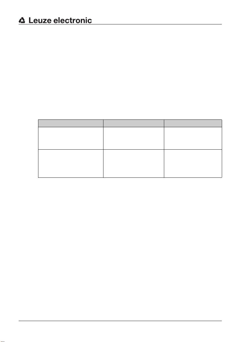
Table 1.1: Documents on the S300 Safety Position Switch
Purpose and target group Title Source
Detailed information for all
users
S300 Safe implementation
and operation (this document)
About this document
On the Internet, download
from: http://www.leuze.com /
s300/
Basic information for technicians and operating company
S300 Application information Print document part
no. 607238 included in the
delivery contents of the
product
TNT 35/7-24V
Leuze electronic S300 5
Page 6
About this document
1.2 Used symbols and signal words
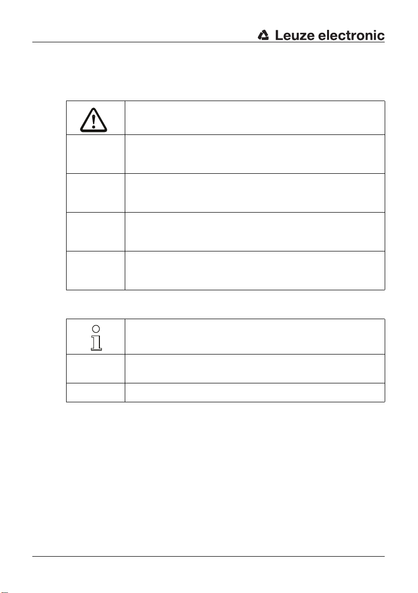
Table 1.2: Warning symbols and signal words
Symbol for dangers
NOTICE Signal word for property damage
CAUTION Signal word for minor injury
WARNING Signal word for severe injury
DANGER Signal word for life-threatening danger
Indicates dangers that may result in property damage if the measures for
danger avoidance are not followed.
Indicates dangers that may result in minor injury if the measures for danger avoidance are not followed.
Indicates dangers that may result in severe or fatal injury if the measures
for danger avoidance are not followed.
Indicates dangers that will result in severe or fatal injury if the measures
for danger avoidance are not followed.
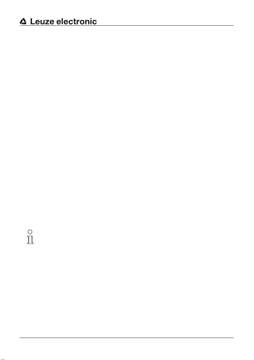
Table 1.3: Other symbols
Symbol for tips
Text passages with this symbol provide you with further information.
Symbols for action steps
ª
Text passages with this symbol instruct you to perform actions.
xxx Placeholder in the product description for all variants
6 S300 Leuze electronic
Page 7
2 Safety
Before using the Safety Position Switch, a risk evaluation must be performed
according to valid standards (e.g. EN
ISO 14121). For mount ing, opera ting and testing, d ocument S300 Safe imple-
EN
mentation and operati on, app licati on infor mation as wel l as all applic able na tional
and international standards, regulations, rules and directives must be observed.
Observe and print out relevant and supplied documents and distribute to the
affected personnel.
The following sta nda rds a pply for the risk e val ua tion a t the protective dev ice prior
to using the Safety Position Switch:
• EN ISO 14121, Safety of machinery, risk evaluation
• EN ISO 12100-1, Safety of machinery
• EN ISO 13849-1, Safety-related parts of control systems
The realizable category of integratio n in control circuits acc. to EN ISO 13849 -1 is
dependent on the used contact block, wiring and mechanical conditions.
In particular, the fo llowin g nationa l and i nternationa l legal regulatio ns apply for the
start-up, technical inspections and work with Safety Position Switch:
• Machinery directive 2006/42/EC
• Low voltage directive 2006/95/EC
• Use of work equipment directive 89/655 EEC
• Safety regulations
• Accident-prevention regulations and safety rules
• Ordinance on Industrial Safety and Health and Labor Protection Act
• Device Safety Act
Safety
ISO 12100-1, EN ISO 13849-1,
For safety-related information you may also contact the local authorities (e.g.,
industrial inspectorate, employer's liability insurance association, labor inspectorate, labor protection and health authority).
Leuze electronic S300 7
TNT 35/7-24V
Page 8
Safety
2.1 Approved purpose and foreseeable improper operation
2.1.1 Proper use
• The Safety Switch must only be used after it has been selected in accordance with the respectively applicable instructions and relevant standards,
rules and regulations regarding labor protection and safety at work, and
after it has been installed on the machine, connected, commissioned, and
checked by a competent person.
• When selecting the Safety Switch it must be ensured that its safety-related
capability meets or exceeds the req uire d pe rformance level PLr ascertained
in the risk assessment.
• It must be in perfect condition and inspected regularly.
• The switching process must only be triggered by an actuator approved for
this Safety Switch as w ell as a s teering device in acco rda nce with the spe ci fications. Both must be connected to the fixed actuator holder or moveable
guard in a permanent and tamperproof manner.
WARNING
A running machine can cause severe injuries!
ª Make certain that, during all conversi ons, maintenan ce work and inspec tions,
the system is securely shut down and protected against being restarted
again.
S300 Safety Switches must be connected in such a way that a dangerous state
can only be activated while the protective device is closed and so that the
dangerous state s tops up on ope ning of the protective d ev ice . It mus t not be used
if the point of o peration c an be a ccessed d uring the lag t ime befor e the dan gerous
state has ended.
Connection conditions:
• the dangerous state can only be activated while the protective device is
closed
• opening the protective device while the machine is running triggers a stop
command and ends the dangerous state
8 S300 Leuze electronic
Page 9
Safety
Furthermore, the S300 Safety Position Switch must not be used under the
following conditions:
• the actuation surface (e.g. of the machine or sliding gate) for the actuator is
not form-fitting with positive actuation
• rapidly changing ambient temperature (leads to condensation)
• in the event of strong physical shoc ks
• in explosive or easily flammable atmospheres
• the mounting locations are not sufficiently stab le
• the safety of multiple persons is dependent on the function of this Safety
Switch (e.g. nuclear power plants, trains, aircraft, motor vehicles, incinerators, medical device s)
For machines with longer slowdowns, a Safety Locking Device must be used.
Handling the Safety Position Switch:
ª Observe the permissible environmental conditions for storage and operation
(see chapter 14).
ª Immediately replace damaged Safety Position Switch according to these
instructions.
ª Use cable gland, insulation materials and connecting wires of the appropriate
protection rating.
ª Protect the Safety Position Switch from penetrating foreign bodies (e.g. shav-
ings, sand and blasting agent).
ª Before performing painting work, cover the actuatio n head, a ctuator a nd name
plate.
ª Immediately clean any contamination from the Safety Position Switch that
impacts function according to these instructions.
ª Make no structural changes to the Safety Position Switch and/or actuator.
ª The switching direction may only be changed following an adequate risk eval-
uation and according to the dangerous direction of movement.
ª The Safety Switch must be exchanged after a maximum of 20 years.
TNT 35/7-24V
Leuze electronic S300 9
Page 10

Safety
2.1.2 Foreseeable misuse
Any use other than that defined under the "approved purpose" or which goes
beyond that use of the Safety Switch is considered improper use!
E.g. - using without non-detachably mounted actuator or start-up device
• looping into the safety circuit parts that are not relevant to safety
• using the switch as a limit stop
2.2 Competent personnel
Prerequisites for competent personnel:
• suitable technical training
• knows the rules and re gulations for labor protect ion, safety at work and
safety technology and can assess the safety of the machine
• knows the instructio ns for the Safety Position Switch and the machine
• was instructed by the respons ible i ndividua ls on the mountin g and opera tion
of the machine and of the Safety Position Switch
2.3 Responsibility for safety
Manufacturer and operating company must ensure that the machine and implemented Safety Position Switch function properly a nd that all affected person s are
adequately informed and trained.
The type and content of all imparted information must not lead to unsafe actions
by users.
The manufacturer of the machine is responsible for:
• safe machine cons truc tion
• safe implementation of the Safety Position Switch
• imparting all relevant information to the operating company
• adhering to all regulations and directives for the safe starting-up of the
machine
The operating company is responsible for:
• instructing the operating personnel
• maintaining the safe operation of the machine
• adhering to all regulations and directives for labor protection and safety at
work
• regular testing by competent personnel
10 S300 Leuze electronic
Page 11

2.4 Exemption of liability
Leuze electronic GmbH + Co. KG is not liable in the following cases:
• Safety Position Switch is not used as intended
• safety notices are not adhered to
• mounting and electrical connection are not properly performed
• reasonably foreseeable misuse is not taken into account
Safety
Leuze electronic S300 11
TNT 35/7-24V
Page 12
Device description
1
2
3
4
1
2
3
4
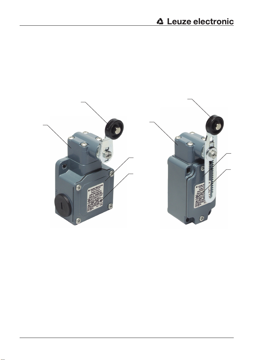
3 Device description
The Safety Position Switch of the S300 seri es is an ele ct ro-m echanical switching
device in a h ousing made of metal o r self -extingui shing, highly v iscous plastic; the
device satisfies protection rating IP
Models with different actua tors, contact sets and connection options are available.
The 300
tions.
series can therefo re c over a v ariety of m echan ical and el ectrical appli ca-
67.
1 Actuator head
2 Actuator
12 S300 Leuze electronic
3 Housing cove r
4 Name plate (connection data, production code and year of manufacture)
Page 13
Device description
56
57
18
33
14.5
6
14.5
40
4
13
50
107
5.2x6.2
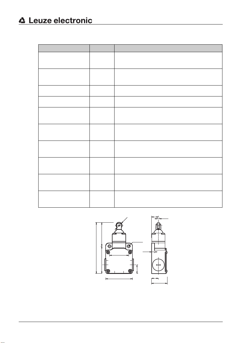
Table 3.1: S300 Safety Position Switch
Article Part No. Description
S300-M0C3-M20-15 63000300 1NC + 1NO, metal design roller plunger, 3 cable
S300-M13C3-M20-15 63000301 2NC + 1NO, metal design roller plunger, 3 cable
S300-M0C3-M20-31 63000302 1NC + 1NO, metal design roller le v er, 3 cable entries
S300-M13C3-M20-31 63000303 2NC + 1NO, metal design roller lev er, 3 cable entries
entries
entries
S300-M13C3-M20-CB 63000304 2NC + 1NO, metal design, short actuator holder,
S300-M13C3-M20-SB 63000305 2NC + 1NO, metal design, long actuator holder,
S300-P13C1-M20-CB 63000306 2NC + 1NO, plastic design, short actuator holder,
S300-P13C1-M12-CB 63000307 2NC + 1NO, plastic design, short actuator holder,
S300-P13C1-M20-SB 63000308 2NC + 1NO, plastic design, long actuator holder,
S300-P13C1-M12-SB 63000309 2NC + 1NO, plastic design, long actuator holder,
3 cable entries
3 cable entries
1 cable entry
1 cable entry / M12 plug
1 cable entry
1 cable entry / M12 plug
TNT 35/7-24V
Leuze electronic S300 13
Figure 3.1: Dimensions of S300-M0C3-M20-15 and S300-M13C3-M20-15 in
mm
Page 14

Device description
56
57
18
33
14.5
6
40
31
7
20
36
55
62
22
119
5.2x6.2
56
57
18
33
14.5
6
40
31
22
M 5
3028
5.2x6.2
56
57
18
33
14.5
6
40
M 5
31
41
22
28
5.2x6.2
Figure 3.2: Dimensions of S300-M0C3-M20-31 and S300-M13C3-M20-31 in
mm
Figure 3.3: Dimensions of S300-M13C3-M20-CB in mm
Figure 3.4: Dimensions of S300-M13C3-M20-SB in mm
14 S300 Leuze electronic
Page 15

Device description
5.3x7.3
40
30
39
30
60
5.3
16
6
28
M 5
31.5
31
22
5.3x7.3
40
30
39
30
60
5.3
16
6
28
M 5
42.5
31
22
15
M12x1
23
13.3
Figure 3.5: Dimensions of S300-P13C1-M20-CB and S300-P13C1-M12-CB
in mm
Figure 3.6: Dimensions of S300-P13C1-M20-SB and S300-P13C1-M12-SB
in mm
Figure 3.7: Dimensions of S300-P13C1-M12-xxx in mm (M12 plug dimensions)
Leuze electronic S300 15
The actuator head can be turned in 90° increments and set to 4 approach directions. The roller lever can be mounted with a 180° rotation and can be positioned
in 10° increments.
TNT 35/7-24V
Page 16

Device description
10°
Figure 3.8: Adjustment options
16 S300 Leuze electronic
Page 17

4 Functions
The Safety Position Switch signals to the safety switching device whether the
protective device is closed. Depending on actuator and set actuation directions,
the Safety Position Switch can also signal alternating directions of danger situa
tions. Release of the actuator closes the safety contacts; pressure on the actuator
forces opening of the safety contacts upon opening of the protective device (e.g.
a sliding gate). As a result, the machine can only be switched on if the protective
device is closed.
Functions
-
Leuze electronic S300 17
TNT 35/7-24V
Page 18

Applications
5 Applications
The Safety Position Switch is suitable for e.g. the following protective devices:
• turning or sliding protective hoods and protective flaps
• laterally moveable protective gratings or sliding gates
• machine-actuated supplementary cut-off (e.g. in combination with other
Safety Switches)
18 S300 Leuze electronic
Page 19

6 Mounting
WARNING
Severe accidents may result if the Safety Position Switch is not mounted
properly!
The protective functi on of th e Safety Position Switch i s only e nsu red if a ppropriately and professionally mounted for the respective, intended area of application.
ª Mounting may only be performed by competent personnel.
ª Observe standards, regulations and these instructions.
ª Observe mounting conditions exactly.
ª Use separate mechanical limit stop (see figure 6.3).
ª Set the distances to the actuator and its angles so that it is impossible to cir-
cumvent or encompass the protective device.
ª Protect the housing from materials penetrating the enclosure (envir onmental
conditions (see chapter 14)).
ª Test to ensure proper function.
6.1 Adjusting the switching and approach direction
ª Loosen the 4 screws on the actuator head.
Mounting
ª Lift the actuator head.
Leuze electronic S300 19
TNT 35/7-24V
Page 20

Mounting
Severe accidents may result if the switching function is not set properly!
ª Set the switching direction so that the NC contac ts open upo n opening of th e
ª If necessary, set the internal plunger to the correct switching direction in 90°
WARNING
protective device.
increments (relative to the NC contacts).
20 S300 Leuze electronic
Page 21

Mounting
10°
ª Place the actuator head on the Safety Position Switch in the desired approach
direction.
ª Tighten the 4 screws on the actuator head with 0.8–1.2 Nm.
ª If necessary, loosen the screw on the actuator (here: roller lever) and adjust it
appropriately (rotate 180° and/or turn in 10° increments).
ª If necessary, tighten the screw on the roller lever with 0.8–1.2 Nm.
Leuze electronic S300 21
TNT 35/7-24V
Page 22

Mounting
6.2 Mounting the Safety Position Switch
Mounting conditions
The stop command must be triggered through pressure on the Safety Position
Switch upon opening of the protective devic e, never by releas ing the Safety Po si
tion Switch.
Correct Wrong
Figure 6.1: Mounting example with a turning protective device
-
Correct
Wrong
Figure 6.2: Mounting example with a sliding protective device
22 S300 Leuze electronic
Page 23

Correct Wrong
≤
45°
≤
45°
>
45°
1
Figure 6.3: Mechanical limit stop (1)
Mounting
Mechanical load exceeds
Correct
specifications; stability not
ensured
Wrong
Figure 6.4: Roller plunger actuation
Leuze electronic S300 23
TNT 35/7-24V
Page 24

Mounting
30°
90°
Actuator: roller plunger j v
– – S300-M0C3-
15° 1.0 0.04 4.0
30° 0.5 0.02 2.0
45° 0.3 0.01 1.0
Mechanical load exceeds
Correct
specifications; stability not
ensured
(m/s) v
max
(mm/s) v
min
M20-15
min
S300-M13C3M20-15
Wrong
(mm/s)
Figure 6.5: Roller lever actuation
Actuator: roller lever j v
– – S300-M0xxx S300-M13xxx
15° 2.5 0.07 9.0
30° 1.5 0.07 8.0
45° 1.0 0.07 7.0
60° 0.75 0.07 7.0
24 S300 Leuze electronic
(m/s) v
max
(mm/s) v
min
(mm/s)
min
Page 25

Mounting
Mounting
Prerequisites for mounting:
• actuation direction is set
• fully assembled
NOTICE
The Safety Position Switch may be damaged if mounted improperly!
Safety Position Switch is not suitable for large mechanical loads.
ª Observe mounting conditions and dimensions exactly.
ª Mount covers to protect against foreseeable damages.
ª Select the mounting location so that the following conditions are satisfied:
• should be form-fitting to protect ag ainst changes in posi tion; se cured mo unting is possible
• corresponding actuating element (moveable guard, control cam) is sufficiently secured against changes in positi on an d the actua tor is actuated w ith
positive force
• accessible to qualified personnel for testing and replacement
ª Position washers and screw down Safety Position Switch with 2–3 Nm.
Leuze electronic S300 25
TNT 35/7-24V
Page 26

Electrical connection
22
21
14
13
22
21
14
13
22
21
34
33
12
11
22
21
34
33
12
11
7 Electrical connection
WARNING
Serious accidents may result if the electrical connection is faulty!
ª Electrical connection may only be performed by competent personnel.
7.1 Connecting the contact bloc k
Prerequisites:
• temperature stability of the cable insulation material must be greater than
the maximum temperature of the housing (see chapter 14)
• cable gland with appropriate protection rating
• maximum current load is observed (see chapter 14)
Figure 7.1: 1NC + 1NO (S300-M0C3-xxx)
Figure 7.2: 2NC + 1NO (S300-M13C3-xxx, S300-P13C1-M20-xxx)
26 S300 Leuze electronic
Page 27

Electrical connection
3
4
5
6
7
8
1
1
7
6
5
4
3
2
8
0
2.2
6
1.1
4
0
30°
75°
17°
60°
Figure 7.3: Pin assignment of the 8-pin M12 plug (S300-xxx-M12-xxx)
DANGER
Risk of death by electric shock!
ª Interrupt the voltage supply to the Safety Position Switch.
ª Unscrew the housing cover.
ª Connect the contact block according to the appli cation-spec ific circu it diagram .
ª Tighten cable terminal screws with 0.6–0.8 Nm.
ª Tighten the housing cover with 0.8–1.2 Nm.
7.2 Contact block characteristics
In the following, the switching behavior when the actuator is in motion is represented schematically. The bar color changes depending on the motion, whereby
the changing of the bar color sends a signal to the switching point. Movement is
specified either in degrees, or when no unit of measurement is given, in millimeters.
Figure 7.4: S300-MOxxx-15 Figure 7.5: S300-MOxxx-31
Leuze electronic S300 27
TNT 35/7-24V
Page 28

Electrical connection
1.5
3
2
0
6
0 75°23°
43°
29°
0 75°23°
43°
29°
Var. B
Var. A
-K3
-K4
14 24 42
13 23 41
-K4-K3
0V 0V
PE PE
-K3
-K4
+24V
0V
MSI-SR4
A1
A2
S22 S12 S31 S33 S34 S35
2 AOPD-
1 AOPD+
33
34
2 AOPD+
IV-0
RES-0
RES-I
1
2
L+
*
x1
x2
L-
21
-A1
222122
S300-M0C3-M20-31
S300-M0C3-M20-31
closed
open
13 14
13 14
1
2
+24V +24V
1
2
1
2
L+ L+
A1
A2
-K3
L- L-
A1
A2
-K4
**
**
1
2
1
2
-A2
-A3
Figure 7.6: S300-M13xxx-15 Figure 7.7: S300-M13xxx-31
075°15°
35°
21°
Figure 7.8: S300-M13xxx-CB, S300-
M13xxx-SB, S300-P13xxxCB, S300-P13xxx-SB when
the actuator is used: AC-
Figure 7.9: S300-M13xxx-CB, S300-
M13xxx-SB, S300-P13xxxCB, S300-P13xxx-SB when
the actuator is used: AC-PL
SL-R, AC-AL-R, AC-LL-R
* Automatic start! It must be impossible to reach or walk behind the interlock device!
** Spark extinction circuit, suitable spark extinction provided
Figure 7.10: Connection example S300-M0C3-M20-15
28 S300 Leuze electronic
Page 29

8 Setting the device into service
Prerequisites:
• Safety Position Switch is mounted and connected according to these
instructions
• operating personnel have been trained in the correct use
ª Test the function of the Safety Position Switch (see chapter 9).
The Safety Position Switch is then ready for use.
Setting the device into service
Leuze electronic S300 29
TNT 35/7-24V
Page 30

Testing
9 Testing
S300 Safety Positio n Switches are main tenance-f ree. Neverth eless, th ey must be
replaced after maximum 5,000,000
ª Always replace the entire Safety Position Switch including actuator.
ª For the testing intervals, observe nationally applicable regulations.
ª Document all tests in a comprehensible manner.
9.1 To be performed prior to the initial start-up by competent personnel
ª Check whether the Safety Position Switch is operated acc ording to its specified
environmental conditions (see chapter 14).
ª Check whether the Safety Position Switch is mo unte d i n a fo rm -fitti ng ma nne r
according to its specifications(see chapter 6.2).
ª Check whether the actuator is form-fitting with positive actuation.
ª Check whether the switching direction was set corre ctly and the stop command
is output as soon as opening of the protective device begins.
ª Test to ensure proper mechanical and electrical function (see chapter 9.2).
9.2 To be performed periodically by competent personnel
switching cycles.
Mechanical function
ª Stop the dangerous state and open the protective device.
ª Check that the components are securely fastened.
ª Test the cable entry for leaks.
ª Check Safety Position Switch and a ctu ato r fo r d am ag e, dep os its , deformation
and wear.
ª Manually actuate roller lever or roller plunger (actuator) several times and
check for ease of motion.
ª Check the actuating surface (e.g. of the machin e or s li din g ga te) f or th e ac tua-
tor for wear.
ª Check the interaction of the actuation surface and the actu ator to ensure that it
is form-fitting with positive actuation.
30 S300 Leuze electronic
Page 31

Electrical function
WARNING
Severe accidents may result if tests are not performed properly!
ª Make certain that there are no persons in the danger zone.
ª Stop the dangerous state and open the protective device.
ª Make certain that the machine cannot be st arted whi le the pr otecti ve dev ice is
open.
ª Close the protective device and start the machine.
ª Test several times whether the machine stops upon opening of the protective
device.
ª Test whether the dangerous state ends before the point of operation can be
reached.
9.3 To be performed daily by the operating personnel
WARNING
Severe accidents may result if tests are not performed properly!
ª Make certain that there are no persons in the danger zone.
Testing
ª Stop the dangerous state and open the protective device.
ª Check the Safety Position Switch and actuator for damage or tampering.
ª Make certain that the machine cannot be st arted whi le the pr otecti ve dev ice is
open.
ª Close the protective device and start the machine.
ª Test whether the machine stops upon opening of the protective device.
Leuze electronic S300 31
TNT 35/7-24V
Page 32

Cleaning
10 Cleaning
There must be no soiling (e.g. shavings and dust) present, especially in the actuator of the Safety Position Switch.
Prerequisites for cleaning:
• protective device is opened and machine is switched off
• voltage supply to the Safety Position Switch is interrupted
ª Regularly clean the Safety Position Switch, actuator and ac tuation surface (e.g.
of the machine or sliding gate) (e.g with a vacuum cleaner).
32 S300 Leuze electronic
Page 33

11 Disposing
ª The nationally valid regulations for electro-mechanical components are to be
observed when disposing.
Disposing
Leuze electronic S300 33
TNT 35/7-24V
Page 34

Service and support
12 Service and support
Telephone number for 24-hour standby service:
+49 (0) 7021/ 573-0
Service hotline:
+49 (0) 8141/ 5350-111
Monday to Thursday, 8.00 a.m. to 5.00 p.m. (UTC+1)
Friday, 8.00 a.m. to 16.00 p.m. (UTC +1)
E-mail:
service.protect@leuze.de Return address for repairs: Service Center
Leuze electronic GmbH + Co. KG
In der Braike 1
D-73277 Owen - Teck / Germany
Leuze electronic offers a regular safety inspection by a competent person.
34 S300 Leuze electronic
Page 35

13 Accessories
Table 13.1: Accessories for the S300 Safety Position Switch
Article Part No. Description
AC-A-M20-12NPT 63000843 Adapter, M20 x 1.5 on 1/2 NPT
AC-PLM-8 63000845 Built-in plug, M12, metal, with internal 8-pin con-
Accessories
nection cable
CB-M12-5000E-5GF 678055 PUR, 5-pin, 5 m, shielded, M12 coupling, straight,
prefabricated on one end
CB-M12-10000E-5GF 678056 PUR, 5-pin, 10 m, shielded, M12 coupling,
straight, prefabricated on one end
CB-M12-15000E-5GF 678057 PUR, 5-pin, 15 m, shielded, M12 coupling,
straight, prefabricated on one end
CB-M12-25000E-5GF 678058 PUR, 5-pin, 25 m, shielded, M12 coupling,
straight, prefabricated on one end
CB-M12-5000E-8GF 678060 PUR, 8-pin, 5 m, shielded, M12 coupling, straight,
prefabricated on one end
CB-M12-10000E-8GF 678061 PUR, 8-pin, 10 m, shielded, M12 coupling,
straight, prefabricated on one end
CB-M12-15000E-8GF 678062 PUR, 8-pin, 15 m, shielded, M12 coupling,
straight, prefabricated on one end
CB-M12-25000E-8GF 678063 PUR, 8-pin, 25 m, shielded, M12 coupling,
straight, prefabricated on one end
AC-SL-R 63000880 Actuator, straight roller lever with roll
AC-AL-R 63000881 Actuator, tilted roller lever with roll
AC-LL-R 63000882 Actuator, long roller lever with roll
AC-PL 63000883 Actuator, straight porcellain lever
TNT 35/7-24V
Leuze electronic S300 35
Page 36

Accessories
7
20
M 5
10491
7
20
15
M 5
40
24
20
7
M 5
10
34 - 93
1
Ø 9
M 5
2.5
80
11.5
57
13.1 Accessory dimensional drawings
Figure 13.1: AC-SL-R actuator Figure 13.2: AC-AL-R actuator
Figure 13.3: AC-LL-R actuator Figure 13.4: AC-PL actuator
36 S300 Leuze electronic
Page 37

14 Technical data
Table 14.1: General
Technical data
Switch type Interlock device without guard interlocking in
Actuator Plunger actuator, roller actuator with lever,
Approach actuation directions Plunger actuator: 1 x above, 4 x side (90°)
Switching direction of roller plunger Both sides
Switching direction of roller lever Left-right one side, both sides
Approach speed
with angle of approach = 15°, 30°, 45°
Approach speed
with angle of approach = 15°, 30°, 45°, 60°
Actuating path with forced opening S300-M0C3-M20-15: 4 mm
accordance with EN 1088
mounted
Roller actuator: 360°, 4 x lateral (90°)
S300-M0C3-M20-15:
min. 0.04 mm/s, 0.02 mm/s, 0.01 mm/s
max. 1.0 m/s, 0.5 m/s, 0.3 m/s
S300-M13C3-M20-15:
min. 4.0 mm/s, 2.0 mm/s, 1.0 mm/s
max. 1.0 m/s, 0.5 m/s, 0.3 m/s
S300-M0xxx:
min. 0.07 mm/s
max. 2.5 m/s, 1.5 m/s, 1.0 m/s, 0.75 m/s
S300-M13xxx, S300-P13xxx:
min. 9 mm/s, 8 mm/ s, 7 mm/s, 7 mm/ s
max. 2.5 m/s, 1.5 m/s, 1.0 m/s, 0.75 m/s
S300-M13C3-M20-15: 3 mm
S300-M0xxx: 60°
S300-P13xxx, S300-M13xxx
with AC-SL-R, AC-AL-R, AC-LL-R: 40°
with AC-PL: 35°
TNT 35/7-24V
Actuation force Roller plunger: min. 11 N
Roller lever: min. 0.1 Nm
Leuze electronic S300 37
Page 38

Technical data
Mechanical life time without actuator acc.
to IEC 60947-5-1
Actuation frequency according to
IEC 60947-5-1
Service life (T
) in accordance with EN ISO
M
13849-1
Number of cycles before dangerous failure
(B10d) according to EN 61810-2
Usage category in accordance with EN
60947-5-1 with screw terminal connection
Maximum load when using 5-pin cables:
Maximum load when using 8-pin cables:
Usage category in accordance with
EN 60947-5-1 with M12 plug connection
5,000,000 switching cycles
max. 3600 per hour
20 years
40,000,000
AC 15 (Ue / Ie):
250 V / 6 A
400 V / 4 A
500 V / 1 A
DC 13 (Ue / Ie):
24 V / 6 A
125 V / 1.1 A
250 V / 0.4 A
24 V / 4 A(see chapter 13)
24 V / 2 A(see chapter 13)
AC 15: (Ue / Ie)
24 V / 2 A
DC 13: (Ue / Ie)
24 V / 2 A
Dimensions (dimensional drawings) see chapte r 3
Table 14.2: Safety
Protection rating IP 67
Contact protection S300-Mxxx: grounding
S300-M0xxx: protective insulation 0
Contact allocation S300-M0C3-xxx: 1NC + 1NO
Contact material silver alloy
38 S300 Leuze electronic
S300-M13xxx: 2NC + 1NO
S300-P13xxx: 2NC + 1NO
Page 39

Technical data
Switching principle S300-M0xxx: snap-action contact
S300-M13xxx: slow action contact
Opening of contact positive-forced
Rated insulation voltage with screw termi-
nal connection
Rated insulation voltage with M12 plug
connection
Conventional thermal current with screw
terminal connection
Conventional thermal current with M12
plug connection
Short circuit protection in accordance with
IEC 60269-1 with screw terminal connection
Short circuit protection in accordance with
IEC 60269-1 with M12 plug connection
500 V AC, 600 V DC
30 V AC, 36 V DC
max. 10 A
max. 2 A
10 A, 500 V, type aM
2 A, 500 V, type gG
Table 14.3: Housing
Housing material S300-Mxxx: metal
S300-Pxxx: plastic, glass fiber reinforced,
self-extinguishing
Table 14.4: Connection
Number of cable entries S300-MxxxC3xxx: 3
S300-PxxxC1xxx: 1
TNT 35/7-24V
Type of cable entry M20 x 1.5
Conductor cross-section (stranded) with
screw terminal connection
Leuze electronic S300 39
1 x 0.5 mm
2
to 2 x 2.5 mm
2
Page 40

Technical data
Table 14.5: Environment
Temperature range, operation –25 ... +80 °C
Degree of contamination, external,
according to EN 60947-1
3
These tables do not apply in comb ination w ith additio nal M12 plug or con necting
cable except where these components are explicitly mentioned.
40 S300 Leuze electronic
Page 41

15 EC Declaration of Conformity
EC Declaration of Conformity
You can download this EC Declaration of Conformity as a PDF from:
http://www.leuze.com/s300/
Leuze electronic S300 41
TNT 35/7-24V
 Loading...