

RSL 440
RSL 445
Safety Laser Scanner
EN 2018/03 - 50128257
We reserve the right to
make technical changes
S A F E I M P L E M E N T A T I O N A N D O P E R A T I O N
O r i g i n a l o p e r a t i n g i n s t r u c t i o n s

© 2018
Leuze electronic GmbH & Co. KG
In der Braike 1
D-73277 Owen / Germany
Phone: +49 7021 573-0
Fax: +49 7021 573-199
http://www.leuze.com
info@leuze.com
Leuze electronic RSL 440 2

Table of contents
Table of contents
1 About this document ............................................................................................7
1.1 Other applicable documents ................................................................................................... 7
1.2 Downloading configuration software from the Internet ........................................................... 7
1.3 Used symbols and signal words .............................................................................................7
1.4 Checklists................................................................................................................................ 8
2 Safety .....................................................................................................................9
2.1 Intended use ........................................................................................................................... 9
2.1.1 Vapors, smoke, dust, particles ..........................................................................................10
2.1.2 Stray light ..........................................................................................................................10
2.1.3 Obstructions in the protective field ....................................................................................10
2.2 Foreseeable misuse ............................................................................................................. 11
2.3 Competent persons .............................................................................................................. 11
2.4 Disclaimer ............................................................................................................................. 12
2.5 Laser safety notices – Laser class1 for wavelength range outside 400-700 nm ...............12
2.6 Responsibility for safety........................................................................................................ 12
3 Device description ..............................................................................................13
3.1 Device overview.................................................................................................................... 14
3.1.1 Protective function of RSL400 safety sensors.................................................................. 14
3.1.2 Parameters for protective function ....................................................................................15
3.1.3 Device and monitoring functions .......................................................................................15
3.2 Connection unit..................................................................................................................... 16
3.3 Display elements .................................................................................................................. 16
3.3.1 LED indicator.....................................................................................................................16
3.3.2 Alphanumerical display .....................................................................................................17
3.3.3 Field-of-view display..........................................................................................................18
3.4 Mounting system (optional)................................................................................................... 19
3.5 Loop guard (optional)............................................................................................................ 19
4 Configuration and diagnostic software SensorStudio...................................20
4.1 System requirements............................................................................................................ 20
4.2 Installing software ................................................................................................................. 20
4.3 User interface........................................................................................................................ 22
4.4 FDT frame menu................................................................................................................... 23
4.4.1 Project wizard....................................................................................................................23
4.4.2 DTM change......................................................................................................................24
4.4.3 User management.............................................................................................................24
4.4.4 Exiting SensorStudio ........................................................................................................24
4.5 Using configuration projects ................................................................................................. 25
4.5.1 Selecting access level .......................................................................................................27
4.5.2 IDENTIFICATION..............................................................................................................28
4.5.3 PROCESS.........................................................................................................................28
4.5.4 CONFIGURATION ............................................................................................................28
4.5.5 DIAGNOSIS ......................................................................................................................28
4.5.6 SETTINGS ........................................................................................................................29
Leuze electronic RSL 440 3

Table of contents
5 Functions.............................................................................................................31
5.1 Authorization concept of safety sensor................................................................................. 31
5.2 Function modes of safety sensor.......................................................................................... 32
5.2.1 One protective function .....................................................................................................33
5.2.2 One protective function – 100 field pairs ...........................................................................33
5.2.3 Two protective functions.................................................................................................... 34
5.2.4 One protective function – four field mode.......................................................................... 34
5.2.5 Two protective functions – four field mode........................................................................35
5.2.6 One protective function – multi configuration .................................................................... 36
5.2.7 Two protective functions - multi configuration ...................................................................36
5.3 Selectable resolution for hand, leg and body detection ........................................................ 36
5.4 Speed-dependent protective function for vehicles................................................................ 37
5.5 Response time...................................................................................................................... 37
5.6 Configurable start-up behavior ............................................................................................. 37
5.6.1 Automatic start/restart .......................................................................................................37
5.6.2 Start interlock/automatic restart......................................................................................... 37
5.6.3 Start/restart interlock (RES) ..............................................................................................38
5.7 Field pair changeover ...........................................................................................................39
5.7.1 Fixed selection of one field pair.........................................................................................39
5.7.2 Changeover of five field pairs in changeover mode Overlapped monitoring.....................40
5.7.3 Changeover of ten field pairs in changeover mode Fixed changeover moment ............... 41
5.7.4 Changeover of 100 field pairs ...........................................................................................42
5.7.5 Changeover of 2x ten field pairs........................................................................................ 43
5.7.6 Changeover of 10x ten field pairs...................................................................................... 43
5.8 Monitoring of field pair changeover....................................................................................... 43
5.9 Reference contour monitoring .............................................................................................. 44
5.10 Field pair monitoring .............................................................................................................44
5.11 Internal safe time delay......................................................................................................... 44
5.12 EDM contactor monitoring ....................................................................................................44
5.13 E-Stop linkage ...................................................................................................................... 45
5.13.1 Contact-based safety circuit ..............................................................................................45
5.13.2 Linkage of electronic safety-related switching outputs ......................................................46
5.14 Signaling functions................................................................................................................ 46
6 Applications ........................................................................................................47
6.1 Stationary danger zone guarding.......................................................................................... 47
6.2 Stationary point of operation guarding.................................................................................. 48
6.3 Stationary access guarding .................................................................................................. 49
6.4 Mobile danger zone guarding ...............................................................................................50
6.5 Danger zone safeguarding on side-tracking skates.............................................................. 52
6.6 Vehicle navigation................................................................................................................. 53
6.6.1 Signal strength and reflector detection..............................................................................53
Leuze electronic RSL 440 4

Table of contents
7 Mounting..............................................................................................................55
7.1 Basic infos............................................................................................................................. 55
7.1.1 Calculation of safety distanceS ........................................................................................55
7.1.2 Suitable mounting locations ..............................................................................................56
7.1.3 Mounting the safety sensor ...............................................................................................56
7.1.4 Mounting examples ...........................................................................................................59
7.1.5 Information on protective field dimensioning .....................................................................60
7.2 Stationary danger zone guarding.......................................................................................... 63
7.3 Stationary point of operation guarding.................................................................................. 66
7.4 Stationary access guarding .................................................................................................. 67
7.5 Mobile danger zone guarding on DTSs ................................................................................68
7.5.1 Minimum distanceD..........................................................................................................69
7.5.2 Protective field dimensions................................................................................................ 70
7.6 Mobile side guarding on DTSs.............................................................................................. 71
7.7 Mounting accessories ........................................................................................................... 71
7.7.1 Mounting system ...............................................................................................................71
7.7.2 Loop guard ........................................................................................................................72
8 Electrical connection..........................................................................................73
8.1 Electrical supply.................................................................................................................... 73
8.2 Interfaces .............................................................................................................................. 74
8.2.1 Connection cable, control..................................................................................................74
8.2.2 Connection cable with M30 connector ..............................................................................75
8.2.3 Pin assignment of M12 Ethernet interface (communication) ( D-coded)........................... 77
8.3 Connection unit CU429......................................................................................................... 77
8.4 Circuit diagram example ....................................................................................................... 79
9 Configuring the safety sensor ...........................................................................80
9.1 Defining safety configuration ................................................................................................ 80
9.2 Connecting safety sensor to PC ...........................................................................................82
9.2.1 Connection via Ethernet cable ..........................................................................................82
9.2.2 Connection via Bluetooth ..................................................................................................82
9.2.3 Communication between safety sensor and PC ...............................................................82
9.3 Determine the configuration project...................................................................................... 83
9.4 Configuring protective function .............................................................................................84
9.4.1 Creating simple safety configuration .................................................................................85
9.4.2 Entering administration parameters ..................................................................................85
9.4.3 Activating protective function and contactor monitoring ....................................................85
9.4.4 Creating and configuring protective/warning field pairs..................................................... 86
9.4.5 Configuring field pair monitoring........................................................................................ 88
9.5 Defining permissible field pair changeovers .........................................................................88
9.6 Configuring signal outputs ....................................................................................................88
9.7 Saving configuration .............................................................................................................89
9.8 Transferring configuration project to safety sensor............................................................... 89
9.9 Selecting access level .......................................................................................................... 91
9.10 Reset safety configuration ....................................................................................................91
Leuze electronic RSL 440 5

Table of contents
10 Starting up the device ........................................................................................92
10.1 Switching on ......................................................................................................................... 92
10.2 Aligning the safety sensor..................................................................................................... 92
10.3 Unlocking start/restart interlock ............................................................................................ 92
10.4 Shutting down ....................................................................................................................... 93
10.5 Restarting.............................................................................................................................. 93
10.6 Starting up replacement scanner unit ................................................................................... 93
11 Testing .................................................................................................................95
11.1 Before the initial start-up and following modifications........................................................... 95
11.1.1 Checklist for integrator – to be performed prior to the initial start-up and following modifica-
tions...................................................................................................................................95
11.2 To be performed periodically by competent persons............................................................ 96
11.3 Periodically by the operator ..................................................................................................97
11.3.1 Checklist – periodically by the operator............................................................................. 97
12 Diagnostics and troubleshooting ......................................................................98
12.1 What to do in case of failure? ...............................................................................................98
12.2 Diagnostics displays .............................................................................................................98
13 Care, maintenance and disposal .....................................................................102
13.1 Changing scanner unit........................................................................................................ 102
13.2 Cleaning the optics cover ................................................................................................... 103
13.3 Servicing ............................................................................................................................. 104
13.4 Disposing ............................................................................................................................ 104
14 Service and support .........................................................................................105
15 Technical data ...................................................................................................106
15.1 General specifications ........................................................................................................ 106
15.2 Dimensions ......................................................................................................................... 111
15.3 Dimensional drawings: Accessories ...................................................................................113
15.4 Representation of safety sensor status .............................................................................. 121
16 Standards and legal regulations .....................................................................125
17 Order guide and accessories...........................................................................126
18 EC Declaration of Conformity ..........................................................................131
Leuze electronic RSL 440 6
1 About this document
1.1 Other applicable documents
The information on the safety sensor is distributed over several documents to make working with the documents easier. You will find the documents and software for the safety sensor in the following table:
About this document
Purpose and target group of the document Document/software ti-
tle
Software for users of the machine a) for safety sensor diagnostics if a fault occurs and for machine de-
SensorStudio
DTM RSL400
sign engineers for configuring the safety sensor
Notes for the machine design engineer
a)
"Safe implementation
and operation"
(this document)
Notes for the machine design engineer a) for config-
Online help for software Supplied with the safety
uring the safety sensor (software instructions)
Notices regarding mounting, alignment and connection of the safety sensor
"Quick Start Guide
RSL400"
a) Machine identifies the product that the safety sensor is installed in.
1.2 Downloading configuration software from the Internet
Ä Call up the Leuze home page: www.leuze.com.
Ä Enter the type designation or part number of the device as the search term.
Ä The configuration software can be found on the product page for the device under the Downloads tab.
1.3 Used symbols and signal words
Source
Supplied with the safety
sensor on data carrier
PDF, supplied with the
safety sensor on data
carrier
sensor on data carrier
Print document, supplied
with the safety sensor
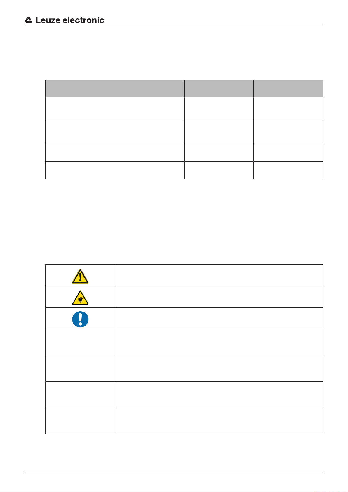
Tab.1.1: Warning symbols and signal words
Symbol indicating dangers to persons
Symbol indicating dangers from harmful laser radiation
Symbol indicating possible property damage
NOTE Signal word for property damage
Indicates dangers that may result in property damage if the measures for danger avoidance are not followed.
CAUTION Signal word for minor injuries
Indicates dangers that may result in minor injury if the measures for danger
avoidance are not followed.
WARNING Signal word for serious injury
Indicates dangers that may result in severe or fatal injury if the measures for
danger avoidance are not followed.
DANGER Signal word for life-threatening danger
Indicates dangers with which serious or fatal injury is imminent if the measures
for danger avoidance are not followed.
Leuze electronic RSL 440 7
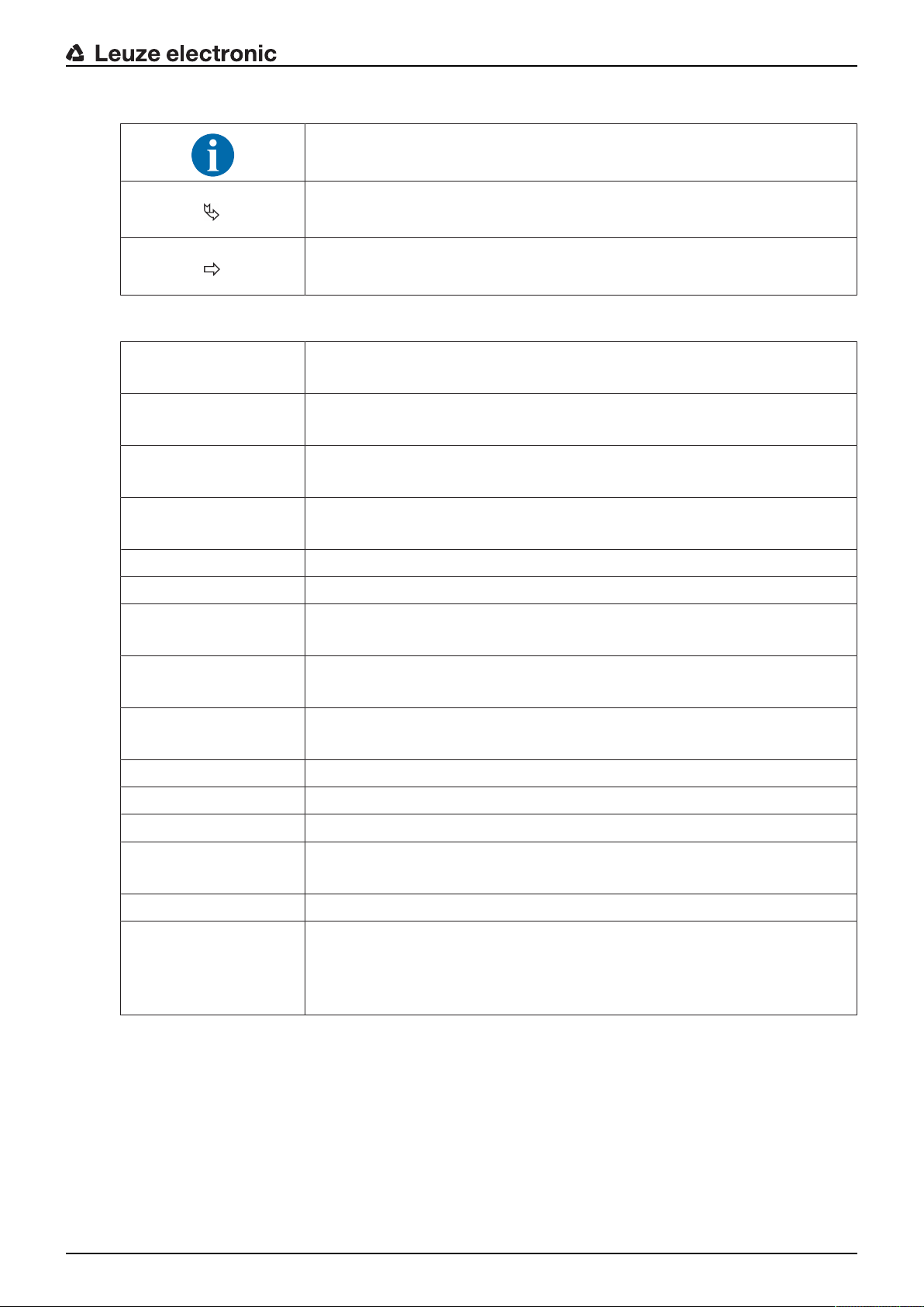
Tab.1.2: Other symbols
Symbol for tips
Text passages with this symbol provide you with further information.
Symbol for action steps
Text passages with this symbol instruct you to perform actions.
Symbol for action results
Text passages with this symbol describe the result of the preceding action.
Tab.1.3: Terms and abbreviations
CS Switching signal from a control
(Controller Signal)
DTM Software device manager of the safety sensor
(Device Type Manager)
EDM Contactor monitoring
(External Device Monitoring)
About this document
FDT Software frame for management of device managers (DTM)
(Field Device Tool)
Field pair A protective field with an associated warning field
DTS Driverless Transportation System
LED LED, display element in the safety sensor
(Light Emitting Diode)
OSSD Safety-related switching output
(Output Signal Switching Device)
PFH
d
Probability of a dangerous failure per hour
(Probability of dangerous Failure per Hour)
PL Performance Level
Quad Two field pairs (four fields) that are monitored simultaneously in four field mode
TSS Transverse Side-tracking Skate
RES Start/restart interlock
(Start/REStart interlock)
SIL Safety Integrity Level
State ON: device intact, OSSDs switched on
OFF: device intact, OSSDs switched off
Locking: device, connection or control/operation faulty, OSSDs switched off
(lock-out)
1.4 Checklists
The checklists serve as a reference for the machine manufacturer or supplier (see chapter 11 "Testing").
They replace neither testing of the complete machine or system prior to the initial start-up nor their periodic
testing by a competent person. The checklists contain minimum testing requirements. Depending on the
application, other tests may be necessary.
Leuze electronic RSL 440 8
2 Safety
Before using the safety sensor, a risk assessment must be performed according to valid standards (e.g.
ENISO12100, ENISO13849-1, IEC61508, ENIEC62061). The result of the risk assessment determines
the required safety level of the safety sensor (see chapter 15.1 "Safety-relevant technical data"). For
mounting, operating and testing, this document as well as all applicable national and international standards, regulations, rules and directives must be observed. Relevant and supplied documents must be observed, printed out and handed to affected persons.
Ä Before working with the safety sensor, completely read and observe the documents applicable to your
task.
In particular, the following national and international legal regulations apply for the commissioning, technical inspections and work with safety sensors:
• Machinery directive 2006/42/EC
• Low voltage directive 2006/95/EC
• EMC directive 2004/108/EC
• Use of work equipment directive 89/655/EEC supplemented by directive 95/63EC
• OSHA 1910 Subpart O
• Safety regulations
• Accident-prevention regulations and safety rules
• Ordinance on Industrial Safety and Health and employment protection act
• Product Safety Law (ProdSG)
Safety
NOTICE
For safety-related information you may also contact local authorities (e.g., industrial inspectorate, employer's liability insurance association, labor inspectorate, occupational safety and
health authority).
2.1 Intended use
The safety sensor protects persons or body parts at points of operation, danger zones or access points of
machines and systems.
A running machine may result in serious injury!
Ä Make certain that the safety sensor is correctly connected and that the protective function of
Ä Make certain that, during all conversions, maintenance work and inspections, the system is
• The safety sensor may only be used after it has been selected in accordance with the respectively applicable instructions and relevant standards, rules and regulations regarding labor protection and safety
at work, and after it has been installed on the machine, connected, commissioned, and checked by a
competent person (see chapter 2.3 "Competent persons").
• When selecting the safety sensor it must be ensured that its safety-related capability meets or exceeds
the required Performance Level PLr ascertained in the risk assessment (see chapter 15.1 "Safety-relevant technical data").
• The safety sensor may only be used in North America in applications that satisfy the requirements
specified by NFPA79.
• With the “access guarding” function, the safety sensor detects persons only when they enter the danger
zone but cannot tell whether there are any persons inside the danger zone. For this reason, a start/
restart interlock in the safety chain is essential in this case.
• The construction of the safety sensor must not be altered. When manipulating the safety sensor, the
protective function is no longer guaranteed. Manipulating the safety sensor also voids all warranty
claims against the manufacturer of the safety sensor.
WARNING
the protective device is ensured.
securely shut down and protected against being restarted.
Leuze electronic RSL 440 9
Safety
• The safety sensor must be inspected regularly by a competent person to ensure proper integration and
mounting (see chapter 15.1 "Safety-relevant technical data").
• The safety sensor must be exchanged after a maximum of 20 years. Repairs or the exchange of wear
parts do not extend the mission time.
CAUTION
Observe intended use!
The protection of personnel and the device cannot be guaranteed if the device is operated in a
manner not complying with its intended use.
Ä Only operate the device in accordance with its intended use.
Ä LeuzeelectronicGmbH+Co.KG is not liable for damages caused by improper use.
Ä Read these operating instructions before commissioning the device. Knowledge of the oper-
ating instructions is an element of proper use.
NOTICE
Comply with conditions and regulations!
Ä Observe the locally applicable legal regulations and the rules of the employer's liability insur-
ance association.
2.1.1
2.1.2
2.1.3
Vapors, smoke, dust, particles
Vapors, smoke, dust and all particles visible in the air can cause the machine to switch off unintentionally.
This can mislead the user into bypassing the safety devices.
Ä Do not use the safety sensor in environments in which heavy vapors, smoke, dust or other visible parti-
cles occur at the beam level.
Stray light
Light sources can impair the safety sensor's availability. Interfering light sources are:
• Infrared light
• Fluorescent light
• Strobe light
Ä Ensure that there are no interfering light sources at beam level.
Ä Prevent reflective surfaces at beam level.
Ä Where applicable, take protective field addition distances into account.
Ä Implement all additional measures to ensure that any special application of any effected beam types
does not impair the safety sensor's operation.
Obstructions in the protective field
Ä Do not bring any additional window materials into the area monitored by the safety sensor.
NOTICE
No screen between optics cover and monitoring area!
Ä Between the optics cover of the safety sensor and the monitored area, no further screen
may be mounted to protect the safety sensor.
Leuze electronic RSL 440 10
2.2 Foreseeable misuse
Any use other than that defined under "Intended use" or which goes beyond that use is considered improper use.
In principle, the safety sensor is not suitable as a protective device for use in the following cases:
• Danger posed by ejected objects or the spraying of hot or hazardous liquids from within the danger
zone.
• Applications in explosive or easily flammable atmospheres.
• Use for outdoor applications or under extreme temperature fluctuations.
Humidity, condensation and other weather influences can impair the protective function.
• Use on vehicles with combustion engines.
Alternators and ignition systems can cause EMC interferences.
NOTICE
Do not modify or otherwise interfere with the safety sensor!
Ä Do not carry out modifications or otherwise interfere with the safety sensor. The safety sen-
sor must not be tampered with and must not be changed in any way.
Ä The safety sensor must not be opened. There are no user-serviceable parts inside.
Ä The construction of the safety sensor must not be altered. When manipulating the safety
sensor, the protective function is no longer guaranteed.
Ä Manipulating the safety sensor voids all warranty claims against the manufacturer of the
safety sensor.
Ä Repairs must only be performed by Leuze electronic GmbH + Co. KG.
Safety
2.3 Competent persons
Connecting, mounting, commissioning and adjustment of the safety sensor must only be carried out by
competent persons.
Prerequisites for competent persons:
• They have a suitable technical education.
• They know the rules and regulations for labor protection, safety at work and safety technology and can
assess the safety of the machine.
• They know the operating instructions for the safety sensor and the machine.
• They have been instructed by the responsible person on the mounting and operation of the machine
and of the safety sensor.
• They perform a task related to the subject matter shortly thereafter and keep their knowledge up to date
through continuous further training.
Certified electricians
Electrical work must be carried out by a certified electrician.
Due to their technical training, knowledge and experience as well as their familiarity with relevant standards
and regulations, certified electricians are able to perform work on electrical systems and independently detect possible dangers.
In Germany, certified electricians must fulfill the requirements of accident-prevention regulations DGUV
Regulation3 (e.g. electrician foreman). In other countries, there are respective regulations that must be observed.
Leuze electronic RSL 440 11
2.4 Disclaimer
LeuzeelectronicGmbH+Co.KG is not liable in the following cases:
• The safety sensor is not used as intended.
• Safety notices are not adhered to.
• Reasonably foreseeable misuse is not taken into account.
• Mounting and electrical connection are not properly performed.
• Proper function is not tested (see chapter 11 "Testing").
• Changes (e.g., constructional) are made to the safety sensor.
2.5 Laser safety notices – Laser class1 for wavelength range outside 400-700 nm
NOTICE
Additional measures for shielding the laser radiation are not necessary (safe for eyes).
WARNING
LASER RADIATION – LASER CLASS 1
The device satisfies the requirements of IEC60825-1:2007 (EN60825-1:2007) safety regulations for a product of laser class1 as well as the FDA Radiation Performance Standards,
21CFR, SubchapterJ, Part1010 and Part1040 with deviations corresponding to "Laser Notice
No.50" from June 24, 2007.
Ä Observe the applicable statutory and local laser protection regulations.
Ä The device must not be tampered with and must not be changed in any way.
There are no user-serviceable parts inside the device.
Ä Repairs must only be performed by Leuze electronic GmbH + Co. KG.
Safety
2.6 Responsibility for safety
Manufacturer and operator must ensure that the machine and implemented safety sensor function properly
and that all affected persons are adequately informed and trained.
The type and content of all imparted information must not lead to unsafe actions by users.
The manufacturer of the machine is responsible for:
• Safe machine construction
• Safe implementation of the safety sensor, verified by the initial test performed by a competent person
• Imparting all relevant information to the operating company
• Adhering to all regulations and directives for the safe commissioning of the machine
The operator of the machine is responsible for:
• Instructing the operator
• Maintaining the safe operation of the machine
• Adhering to all regulations and directives for labor protection and safety at work
• Regular testing by competent persons
Leuze electronic RSL 440 12
3 Device description
1
2
4
5
3
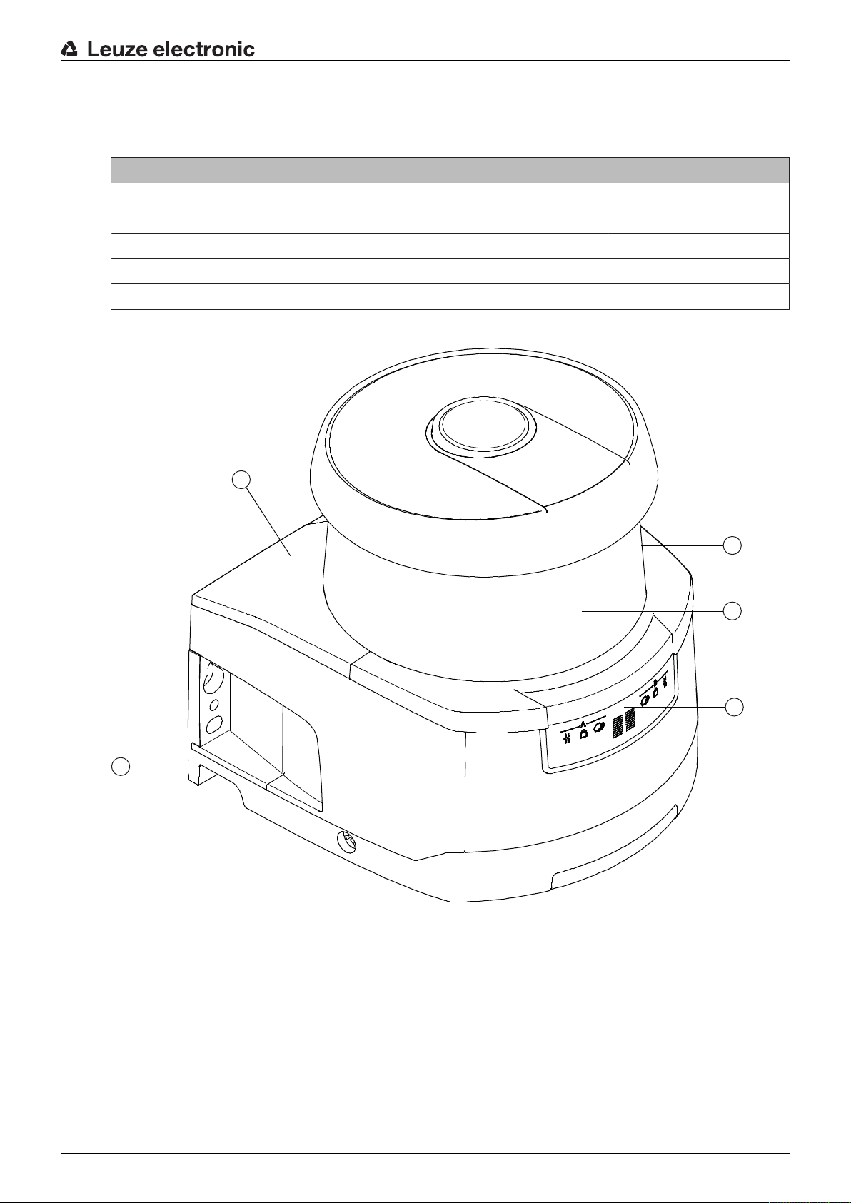
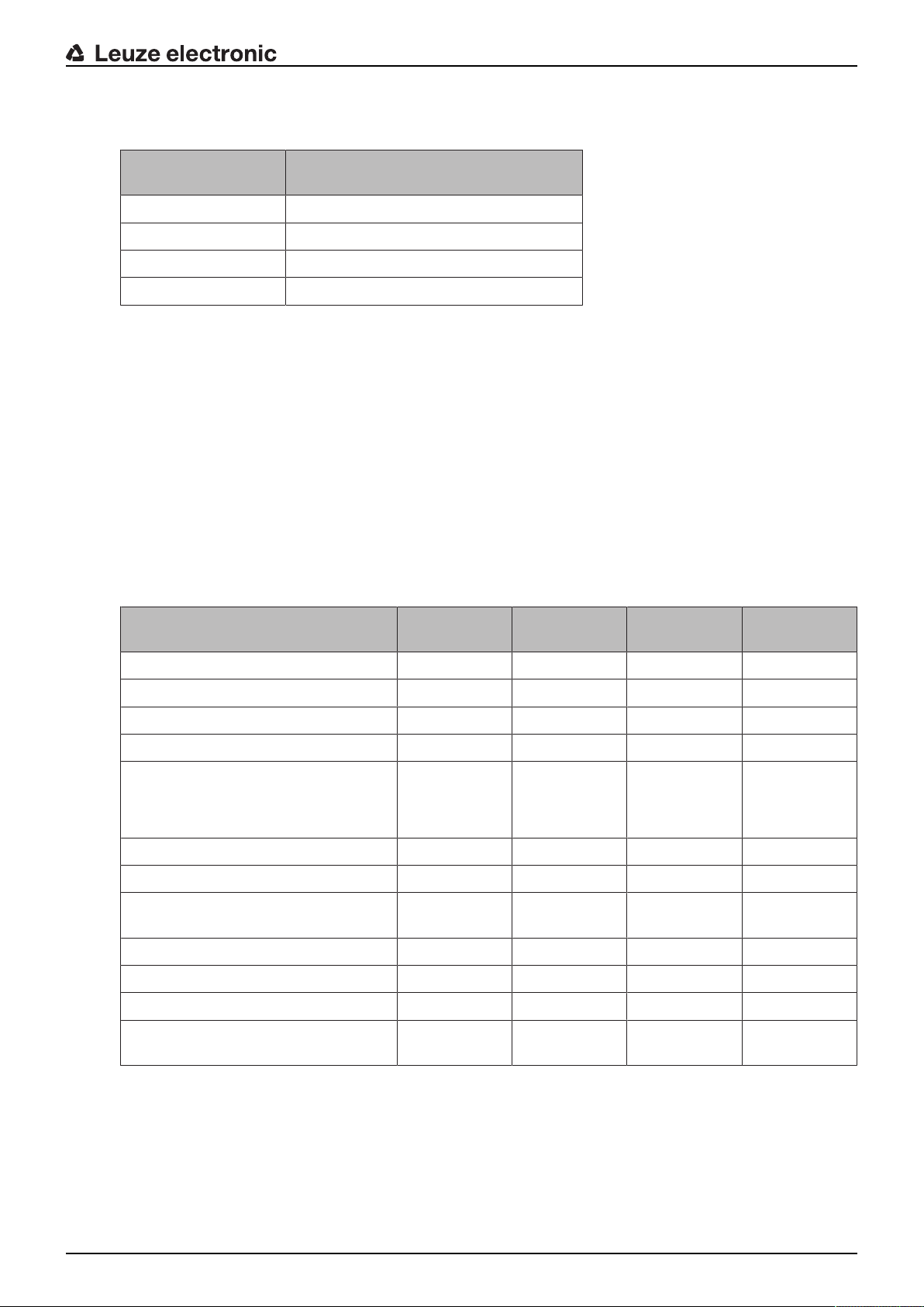
The safety sensors from the RSL400 series are optoelectronic, two-dimensional measuring safety laser
scanners. They satisfy the following standards:
Type in accordance with IEC/EN61496 3
Category in accordance with ENISO13849 3
Safety Integrity Level (SIL) in accordance with IEC61508 2
SILCL in accordance with IEC/EN62061 2
Performance Level (PL) in accordance with ENISO13849‑1 d
Device description
RSL400
1 Scanner unit
2 Connection unit
3 Optics cover
4 Alphanumerical display (displayed)
5 LED indicators
Fig.3.1: Device overview of RSL400 safety laser scanners
Leuze electronic RSL 440 13
All safety sensors of the RSL440 series are equipped as follows:
• Laser scanner with the range class S, M, L or XL:
Device description
Operating range
class
S 3.00
M 4.5
L 6.25
XL 8.25
• 24-digit alphanumerical display
• Integrated electronic spirit level for aligning the safety sensor
• LED indicator
• Connection unit:
• Configuration memory
• Ethernet connection for communication and configuration with the PC/laptop
• Electrical connection to the machine via connection cable
3.1 Device overview
The following table provides an overview of the possible uses, features and functions of the RSL400 safety
sensors.
Tab.3.1: Device overview
Operating range [m]
RSL410 RSL420
RSL425
RSL430 RSL440
RSL445
Stationary danger zone guarding x x x x
Mobile danger zone guarding x x x x
Access guarding x x x x
Point of operation guarding x x x x
Safety-related switching outputs
Protective functionA
Protective functionB
1 OSSD pair
x
-
1 OSSD pair
x
-
2 OSSD pairs
x
x
2 OSSD pairs
x
x
Signal outputs Up to 3 Up to 4 Up to 9 Up to 9
Configurable signal outputs x x x x
Number of changeover-capable pro-
1 10 10+10 100
tective/warning field pairs
E-stop linkage - x x x
Four field mode (quads) x x x x
Internal safe time delay - - x x
Measurement data output optimized
- Only RSL425 - Only RSL445
for vehicle navigation
3.1.1
Protective function of RSL400 safety sensors
The safety sensor transmits periodic light pulses via a rotating deflection unit. The light pulses are scattered
in all directions by obstacles, e.g. persons. A part of the light pulses is received again by the safety sensor
and evaluated. The safety sensor calculates the precise position of the object from the propagation time of
the radiated light and the current angle of the deflection unit at that time. If the object is within a predefined
area, the protective field, the safety sensor performs a safety-related switching function. It switches the
safety-related switching outputs off.
Leuze electronic RSL 440 14

Device description
Only when the protective field is free again does the safety sensor reset the safety-related switching function, either automatically or following acknowledgment, depending on the operating mode.
The safety sensor can even detect people when they are wearing very dark clothes, which have a very
weak diffuse reflectance.
3.1.2
Parameters for protective function
The following parameters for switching off the safety-related switching outputs of the safety sensor are
taken into consideration for the protective function:
• Configurable protective fields
• Reference contour of protective fields
• Configurable field pair changeover
• Selectable resolution for hand, leg or body detection
• Safety sensor response time
• Selectable start-up behavior
The following non-safety-oriented functions and signals also belong to the protective function:
• Configurable warning fields
• Configurable indication signals
Additional functions of the protective function
• Warning field evaluation
• Selectable dynamic contactor monitoring (EDM)
• E-Stop
Two protective functions function mode
• The safety sensor can be configured for two independent protective functions.
• If the safety sensor is configured for one protective function, an internal safe time delay can be selected
for switch-off of the second OSSD pair.
3.1.3
Device and monitoring functions
• Monitoring and release of field pair changeover
• Configurable output of the indication signals for the following functions groups:
• Protective function
• Warning messages
• Error messages
• Diagnostics
• Status messages
Leuze electronic RSL 440 15
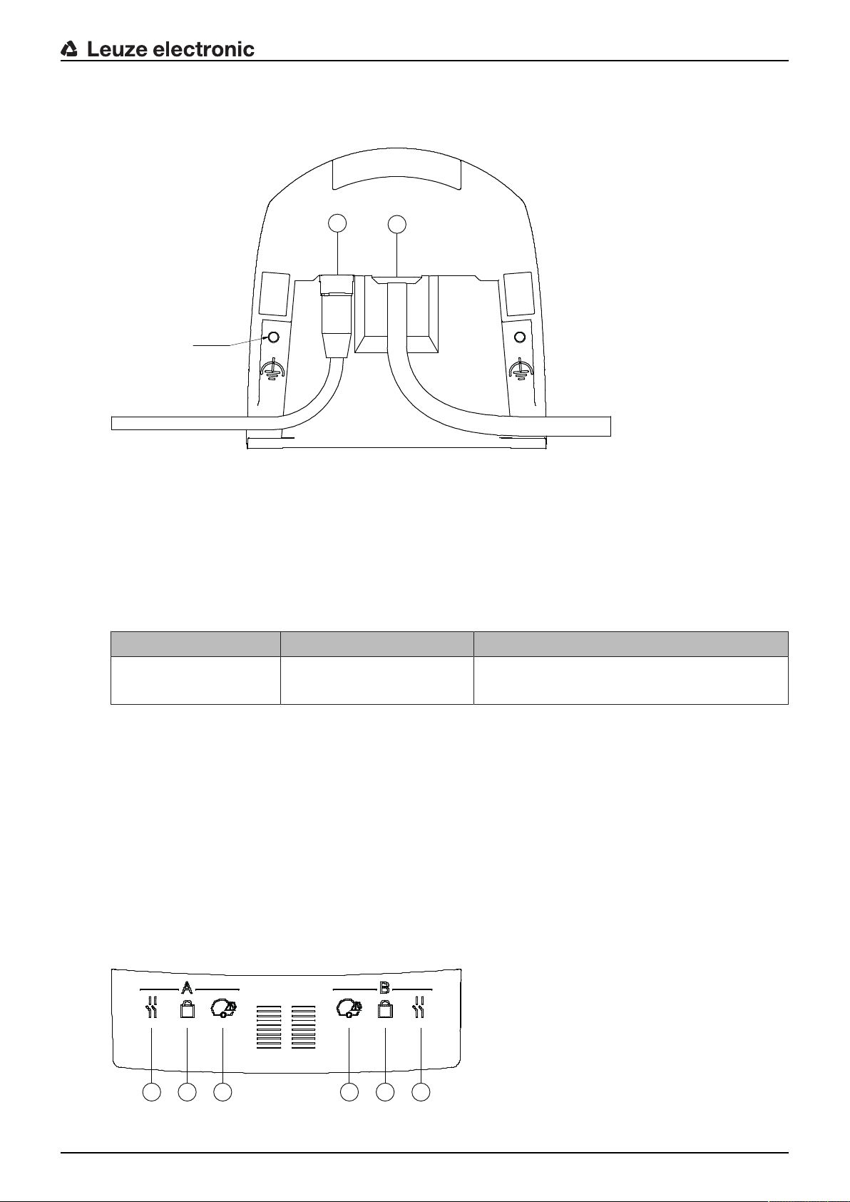
3.2 Connection unit
M5 2x
2
1
1
2 3 4 5 6
The safety sensor is mounted, connected and aligned using the connection unit.
Device description
1 Connection cable, connection to the machine
2 M12 socket, D-coded, Ethernet communication connection
M5 Connection for functional earth with M5x10 self-cutting/self-tapping (gas tightness) and ground strap
Fig.3.2: Device overview, connection unit
Functions of connection unit:
• Attachment point for mounting, either directly or using an optional mounting system.
When devices are swapped out, the connection unit remains mounted and aligned.
• EMC wiring for signal inputs/outputs and supply using connection cable
Safety sensor Connection unit Connection
RSL440 CU429-y
• Connector bushing and EMC for the Ethernet TCP/IP communication and configuration interface to the
PC/laptop
• Memory for the configuration files and automatic parameter transfer in the event of device swap-out
• Quick-release connection to the scanner unit (see Quick Start Guide) for easy device swap-out
3.3 Display elements
The display elements of the safety sensors simplify start-up and fault analysis.
3.3.1
LED indicator
Located on the connection unit are six LEDs for displaying the operating state.
• Protective function A: LEDs 1, 2, 3
• Protective function B: LEDs 4, 5, 6
y=5000, 10000, 25000
Connection cable, 29-wire
5m, 10m, 25m
Leuze electronic RSL 440 16
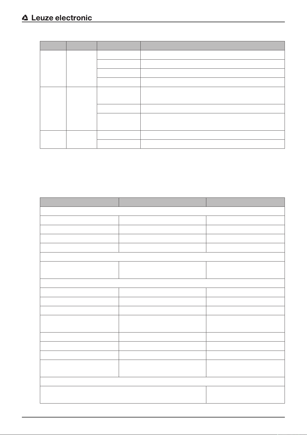
Tab.3.2: Meaning of the LEDs
LED Color State Description
1, 6 Red/green OFF Device switched off
Red OSSD off
Red, flashing Error
Green OSSD on
2, 5 Yellow OFF RES deactivated
RES activated and enabled
Flashing Protective field occupied
ON RES activated and blocked but ready to be unlocked
Protective field free and linked sensor enabled (if applicable)
3, 4 Blue OFF Free warning field
ON Warning field interrupted
Device description
3.3.2
Alphanumerical display
In normal operation, the 24-digit alphanumerical display of the safety sensor shows the monitored protective and warning field pairs. It also provides assistance during detailed error diagnostics (see chapter 12
"Diagnostics and troubleshooting").
Tab.3.3: Alphanumerical displays
Display Description Example
Upon startup without configuration/upon initial commissioning
Sensor type Sensor type 420M
Sensor serial number Sensor serial number SN: 21513123456
Sensor name / Network name Name of the sensor / network A123456789
Configuration necessary Configuration required CONFIG REQUESTED
Repeated until end of booting phase / start phase, then
Spirit level permanent Horizontal alignment in degrees: H
H -3° V +9°
Vertical alignment in degrees: V
Upon startup with configuration
Sensor type Sensor type 410XL
Sensor serial number Sensor serial number SN: 21513123456
Sensor name / Network name Name of the sensor / network A123456789
IP: DHCP/FIX DHCP or permanent IP address IP: DHCP or
10.25.45.2
Bluetooth on/off Bluetooth detection ON/OFF Bluetooth ON
Date of configuration Date of configuration 11/13/2014 08:15
Signature Signature of configuration DG45L8ZU
Level Horizontal alignment in degrees: H
H-3° V+9°
Vertical alignment in degrees: V
Repeated until end of booting phase / start phase, then
Display following configuration of normal operation
e.g. display of active field pair A1.1
Leuze electronic RSL 440 17
Display Description Example
Transfer of the configuration data
AWAITING CONFIG Until downloading of configuration data is confirmed
DOWNLOAD CONFIG During transfer of configuration data
Level
Device description
H +/- ..° V +/- .. ° Horizontal alignment in degrees: H
H -3° V +9°
Vertical alignment in degrees: V
Sensor detection
PING received Display for identification by device
PING received Device name
name
Message
Message via a signal output or diagnosis ID
ProtF A: E123
Device: P007 - wrong Config
Error diagnostics
F… Failure, internal device error
E… Error, external error
U… Usage info, application error
I… Information
P… Parameter, inconsistency in the con-
figuration
For error diagnostics, the error's respective letter is displayed first followed by the number code. An AutoReset is carried out after 10 seconds for errors that do not cause locking, with an unauthorized restart being impossible. In the case of blocking errors, the voltage supply must be separated and the cause of the
error must be eliminated. Before switching on again, the steps taken before initial commissioning must be
repeated (see chapter 10 "Starting up the device").
When the protective field has been free for about 5 seconds, the device switches back to the display in normal operation.
3.3.3
Displays in normal operation
The display in normal operation depends on the operating state of the safety sensor. The display can be
switched off or rotated by 180° by means of the software.
Field-of-view display
The upper and lower limit of the safety sensor's field of view can be displayed by means of horizontal lines
on the optics cover.
Ä Make sure that the safety sensor's field of view is always completely unobstructed.
NOTICE
Always check the protective field configuration!
Ä Check all defined protective fields each time the configuration is changed.
The field-of-view display is a comfort function and is not intended as a substitute for checking the protective field configuration.
Ä The safety sensor's field of view must be completely unobstructed on the application side.
Leuze electronic RSL 440 18

3.4 Mounting system (optional)
Mounting systems and mounting brackets simplify mounting and alignment of the safety sensor. Mounting
systems and mounting brackets are available as accessories (see chapter 17 "Order guide and accessories").
3.5 Loop guard (optional)
The loop guard for the optics cover prevents damage to the safety sensor caused by light contact with foreign objects. The loop guard is available as an accessory (see chapter 17 "Order guide and accessories").
Device description
Leuze electronic RSL 440 19
Configuration and diagnostic software SensorStudio
4 Configuration and diagnostic software SensorStudio
To start up a safety sensor in your application, the safety sensor must be set up according to its specific
use using the configuration and diagnostic software. The software is used to set up the safety configuration
of the safety sensor, to change the communication and diagnostics settings and to perform diagnostic routines. Communication takes place via the PC.
The software is designed according to the FDT/DTM concept:
• You make the individual configurations for the safety sensor in the Device Type Manager (DTM).
• The individual DTM configurations of a project can be called up via the frame application of the Field
Device Tool (FDT).
• Each device DTM has a communication DTM that sets up and monitors the communication connections to the sensor.
NOTICE
Only use the software for safety sensors manufactured by Leuze electronic.
4.1 System requirements
To use the software, you need a PC or laptop with the following specifications:
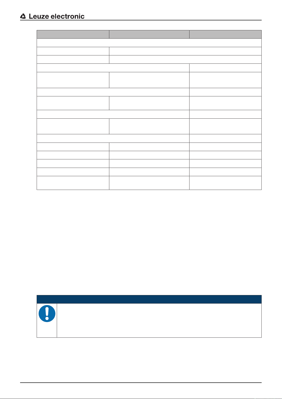
Hard disk space At least 250MB free memory
Screen display Color
External drive DVD drive
Input device Keyboard and mouse or touchpad
Output device Printer (black-white or color)
Interfaces RJ45 Ethernet network
Operating system Microsoft® Windows7 and Windows8.1
NOTICE
Only the term "PC" is used below.
4.2 Installing software
Prerequisites:
• You do not need the safety sensor to install the software on the PC.
• All Windows applications are closed.
If you want to save the protective field or configuration values, you will
need more memory.
Bluetooth (optional) - If the PC does not have integrated Bluetooth technology, use an appropriate USB or PCMCIA adapter if necessary.
NOTICE
The software is installed in two steps:
Ä Installing the SensorStudio FDT frame.
Ä Installing LeSafetyCollection device manager (DTM).
Leuze electronic RSL 440 20
Configuration and diagnostic software SensorStudio
Installing the SensorStudio software
NOTICE
If FDT frame software is already installed on your PC, you do not need the SensorStudio installation.
You can install the device manager (DTM) in the existing FDT frame.
Ä Insert the data carrier.
ð The installation will start automatically.
Ä If installation does not start automatically, double-click the file SensorStudioSetup.exe.
Ä If you want to call up the menu of the CD, double-click the file start.exe.
Ä Select a language for the interface text in the installation wizard and software and confirm with [OK].
ð The installation wizard starts.
Ä Click [Next].
ð The installation wizard opens the software license agreement.
Ä If you want to accept the license agreement, select the appropriate option field and click [Next].
Ä If the suggested installation path is OK, click [Next].
If you want to specify a different path, click the [Browse] button. Select a different path, confirm with
[OK] and click [Next].
Ä Click the [Install] button to start installation.
ð The wizard installs the software and places a shortcut on the desktop ( ).
Ä Click the [Finish] button to complete installation.
Installing LeSafetyCollection device manager (DTM)
Prerequisites:
• The Sensor Studio software is installed on the PC.
• Data carrier inserted.
Ä Double-click the file LeSafetyCollectionSetup.exe.
Ä Select a language for the interface text in the installation wizard and software and confirm with [OK].
ð The installation wizard starts.
Ä Click [Next].
ð The installation wizard opens the software license agreement.
Ä If you want to accept the license agreement, select the appropriate option field and click [Next].
Ä If the suggested installation path is OK, click [Next].
If you want to specify a different path, click the [Browse] button. Select a different path, confirm with
[OK] and click [Next].
Ä Click the [Install] button to start installation.
ð The wizard installs the software.
Ä Click the [Finish] button to complete installation.
NOTICE
During installation of the software, a user admin (without password query) is created so that you
can start the software without user identification. If other users are registered (Tools > User
management in the FDT frame menu), you must log in at the software with a user name and
password.
This setting allows you to connect to the safety sensor and to read out, upload, enter or change
the safety configuration and all settings using the RSL400 device DTM. The password for the
safety sensor only needs to be entered (i.e. the access level only needs to be changed) when
the changes are downloaded to the safety sensor (see chapter 4.5.1 "Selecting access level").
Leuze electronic RSL 440 21
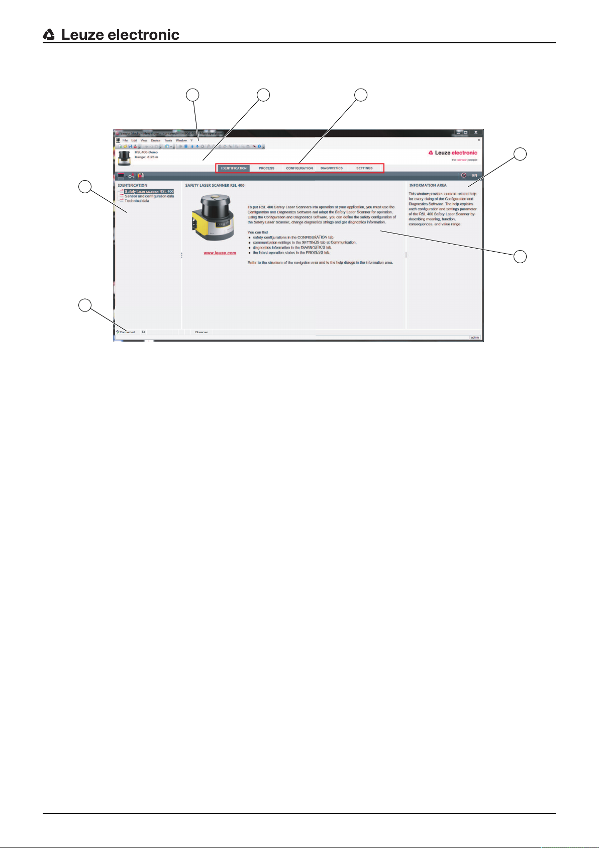
4.3 User interface
2 3
4
5
1
6
7
Configuration and diagnostic software SensorStudio
1 FDT frame menu with toolbar
2 RSL400 device manager (DTM)
3 Navigation tabs
4 Information area
5 Dialog box
6 Status line
7 Navigation area
Fig.4.1: User interface of the software
FDT frame menu
The device managers (DTM) of the safety sensors are created and managed in the FDT frame menu.
Device manager DTM
Configuration projects for setting up the selected safety sensor are created and managed in the device
managers (DTM) of the safety sensors.
Leuze electronic RSL 440 22
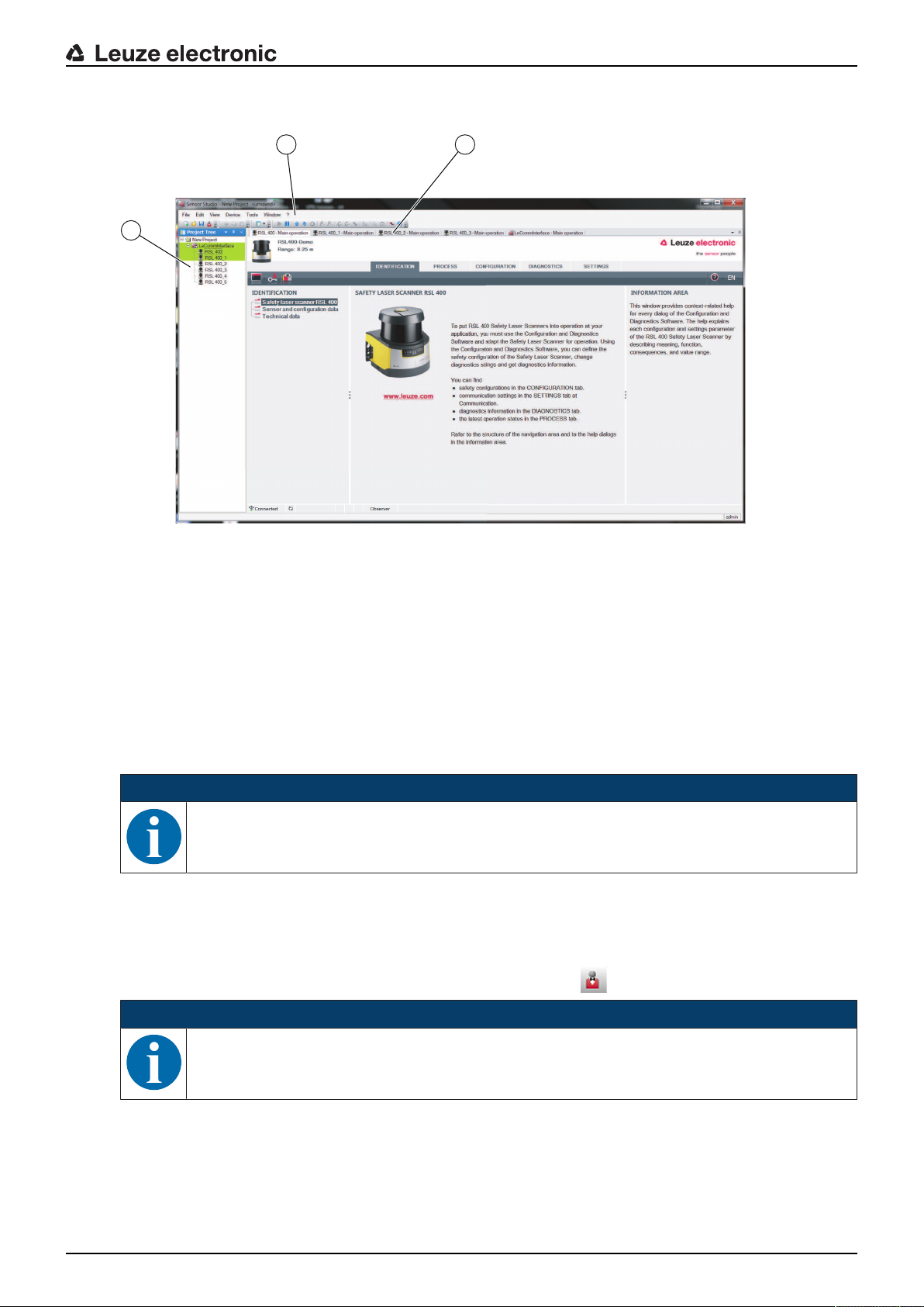
Project tree view
21
3
Configuration and diagnostic software SensorStudio
1 FDT frame menu
2 Device manager (DTM) tabs
3 Project tree view
Fig.4.2: User interface with project tree view
The project tree view shows the structure of the currently installed device managers (DTM). In the project
tree view you can, for example, add copies of an already configured device manager (DTM) quickly and
easily to the DTM structure if you want to operate multiple safety sensors with the same configuration settings.
Example: DTS with safety sensors on front and rear side
4.4 FDT frame menu
NOTICE
You can find complete information on the FDT frame menu in the online help system. Select the
Help menu item in the menu [?].
4.4.1
Project wizard
Using the Project Wizard you can create and change configuration projects for setting up the safety sensor
(see chapter 4.5 "Using configuration projects").
Ä Start the Project Wizard in the FDT frame menu by clicking the button.
NOTICE
Information on the Project Wizard can be found in the online help for the FDT frame menu under
Sensor Studio Options.
Leuze electronic RSL 440 23
Configuration and diagnostic software SensorStudio
4.4.2
4.4.3
DTM change
The DTM Change function makes it easier for you to call up the communication DTM of a device or change
from device DTM to communication DTM.
Ä Start the DTM change function in the FDT frame menu by clicking the button.
NOTICE
Information on DTM change can be found in the online help for the FDT frame menu under Sensor Studio Options.
User management
Using the user management in the FDT frame menu, you can create users, log users in/out and manage
passwords.
Creating users
When creating a user in the user management via Tools > User management in the software frame
menu, select the access level for the user. For information on access permissions and access levels (see
chapter 5.1 "Authorization concept of safety sensor").
Ä In the FDT frame menu, click Tools > User management > Create user.
Logging users in/out
Prerequisites:
• Users have been created
Ä In the FDT frame menu, click Tools > Log in/log out.
4.4.4
Managing passwords
Prerequisites:
• Users have been created
Ä In the FDT frame menu, click Tools > Change password.
NOTICE
Password management via the FDT frame menu applies to all installed device managers (DTM)
of the project.
Whenever write access occurs, the safety sensors of the RSL400 series always check the access level (Engineer, Expert) and the password defined via the device manager (DTM) (SET-
TINGS > Passwords) independently of the password management via the FDT frame menu.
Exiting SensorStudio
When you have finished making the configuration settings, close the configuration and diagnostics software.
Ä Exit the program via File > Exit.
Ä Save the configuration settings as a configuration project on the PC.
You can open the configuration project again at later time via File > Open or with the SensorStudio Project
Wizard ( ).
Leuze electronic RSL 440 24
4.5 Using configuration projects
Configuration projects are created and managed in the device manager (DTM) of the selected safety sensor.
NOTICE
During installation of the software, a user admin (without password query) is created so that you
can start the software without user identification. If other users are registered (Tools > User
management in the FDT frame menu), you must log in at the software with a user name and
password.
This setting allows you to connect to the sensor and to read out, upload, enter or change the
safety configuration and all settings using the RSL400 device DTM. The password for the sensor only needs to be entered (i.e. the access level only needs to be changed) when the changes
are downloaded to the safety sensor (see chapter 4.5.1 "Selecting access level").
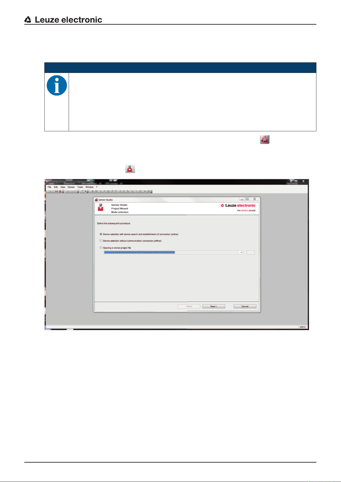
Ä Start the configuration and diagnostics software on the PC by double-clicking the button.
ð The mode selection of the Project Wizard is displayed.
ð If the mode selection is not shown, start the Project Wizard in the FDT frame menu by clicking the
[Project Wizard] button ( ).
Configuration and diagnostic software SensorStudio
Fig.4.3: Project wizard
Ä Select the configuration mode and click [Next].
ð Automatic connection to a connected safety sensor (Online)
ð Device selection without communication connection (offline)
ð Load a saved project again
ð The project wizard displays the SEARCH DEVICES dialog box.
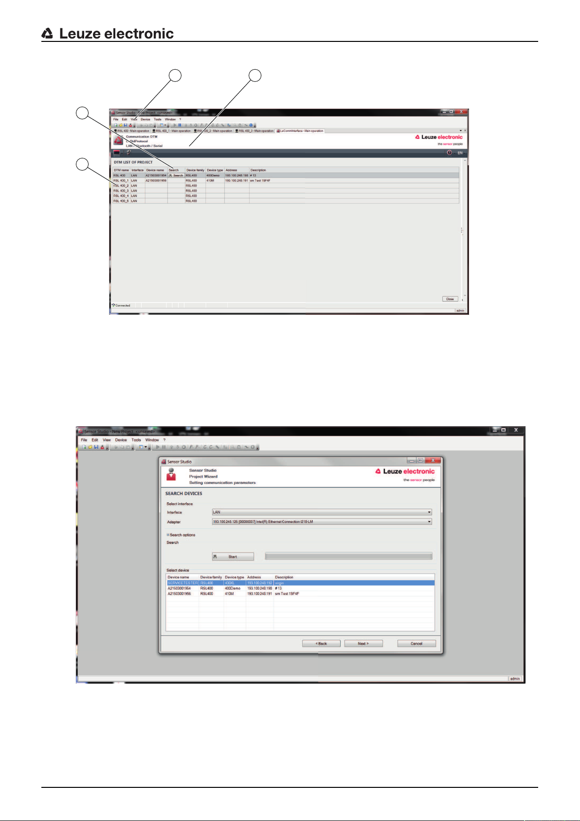
Ä Select the interface and click the [Start] button.
Ä Find the safety sensor for your configuration project using the search function of the communication
DTM.
Leuze electronic RSL 440 25
Configuration and diagnostic software SensorStudio
21
3
4
1 FDT frame menu
2 Communication DTM
3 Device list
4 Search function
Fig.4.4: Communication DTM with search function
ð The project wizard displays the device list of configurable safety sensors in the SEARCH DEVICES di-
alog box.
Fig.4.5: Device selection in project wizard
Ä Select the safety sensor from the device selection list and click [Next].
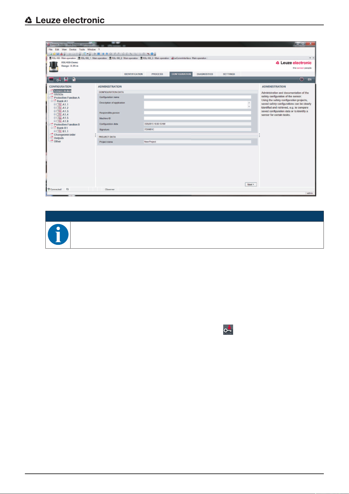
ð The device manager (DTM) of the safety sensor shows the initial screen for the configuration project.
Leuze electronic RSL 440 26
Configuration and diagnostic software SensorStudio
4.5.1
Fig.4.6: Initial screen for safety configuration
NOTICE
The device manager (DTM) starts without querying the access level of the user. During communication with the safety sensor, the safety sensor does however query the access level of the
user. To change the access levels (see chapter 4.5.1 "Selecting access level").
Setting device manager
Using the menus of the device manager (DTM) you can set the parameters of the safety configuration. The
online help system provides information on the menu items and adjustment parameters. Select the Help
menu item in the menu [?].
Selecting access level
Using the device manager you can change the access level of the user if necessary.
For the authorization concept of the software, see chapter see chapter 5.1 "Authorization concept of safety
sensor".
Ä Click in the DTM menu bar on the [Change access level]button ( ).
ð The Change access level dialog box opens.
Ä In the Access level list, select the item Expert, Engineer or Observer and enter the default password or
the password defined for the individual user.
The following access levels are available:
• Observer can read everything (no password)
• Expert can change communication and diagnostics settings (default password = comdiag)
• Engineer can additionally change the safety configuration (default password = safety)
The password is case-sensitive (i.e. a distinction is made between upper-case and lower-case letters).
Ä Confirm with [OK].
Leuze electronic RSL 440 27
Configuration and diagnostic software SensorStudio
4.5.2
4.5.3
IDENTIFICATION
Detailed information on the menu items and setting parameters can be found in the information area and in
the online help. Select the Help menu item in the menu [?].
• RSL400 safety laser scanner
• Sensor and configuration data
• Technical data
PROCESS
Detailed information on the menu items and setting parameters can be found in the information area and in
the online help. Select the Help menu item in the menu [?].
• Sensor display
Device display in the DTM menu
• SENSOR DISPLAY
• STATE OF THE ACTIVE PROTECTIVE AND WARNING FIELDS
• SENSOR DATA
• Measurement contour
• Inputs / outputs
• SENSOR DISPLAY
• CONNECTIONS AND SIGNALS
• Simulation – only with access level Engineer
• Measurement contour
• Inputs / outputs
4.5.4
4.5.5
CONFIGURATION
see chapter 9 "Configuring the safety sensor"
NOTICE
You can only transfer changes made in the CONFIGURATION menu to the safety sensor if you
are logged in with the access level Engineer.
DIAGNOSIS
Adjustment / Alignment
Display of safety sensor alignment using the integrated electronic spirit level
Prerequisites: The software and safety sensor are connected.
Ä In the DIAGNOSIS menu, click the [Align sensor mechanically]button ( ).
ð The safety sensor display shows the horizontal and vertical alignment in degrees.
Visually identify device
If you have installed multiple safety sensors, identify the safety sensor that is connected to the currently
open device manager (DTM).
Prerequisites: The software and safety sensor are connected.
Ä In the DIAGNOSIS menu, click the [Visually identify sensor]button ( ).
ð In the display of the safety sensor connected to the device manager (DTM), the message "PING re-
ceived" flashes for ten seconds.
Reset sensor
Acknowledge messages and faults
Set safety sensor to safety mode
Leuze electronic RSL 440 28
Configuration and diagnostic software SensorStudio
Create and save service file
The service file contains all available information on the safety sensor as well as configuration and settings.
When requesting support, send the service file to the Leuze electronic customer service (see chapter 14
"Service and support").
Sensor display
Device display in the DTM menu
• SENSOR DISPLAY
• STATE OF THE ACTIVE PROTECTIVE AND WARNING FIELDS
• SENSOR DATA
Diagnostics list
Access list
EventLog
4.5.6
SETTINGS
NOTICE
You can only transfer changes made in the SETTINGS menu to the safety sensor if you are
logged in with the access level Engineer.
Communication
• LAN
• DHCP
• CONNECTION SETTINGS
• MAC address
• Bluetooth
• Activate Bluetooth module
• Activate device scan
• Bluetooth address
Data telegrams
A UDP telegram can be configured which sends the status profile of the safety sensor as well as the measurement data to a receiving device connected via Ethernet, e.g. to a PC.
EventLog
Trigger signals output when certain events occur, are recorded and shown in the event list of the safety
sensor.
Information on the monitored signals can be found in the information area and in the online help. Select the
Help menu item in the menu [?].
Sensor display
Activation of the safety sensor alphanumerical display.
Information on the display options can be found in the information area and in the online help. Select the
Help menu item in the menu [?].
Passwords
NOTICE
If a user has forgotten his password for login at the safety sensor or has repeatedly entered the
password incorrectly, he cannot log in at the safety sensor. The CHANGE PASSWORD function
is therefore not available.
To reset the password, a user must generate a reset password and have it confirmed by the
manufacturer.
Leuze electronic RSL 440 29

Configuration and diagnostic software SensorStudio
CHANGE PASSWORD
Ä Define individual passwords for the access levels Engineer and Expert. These passwords replace the
default passwords set by the manufacturer.
The password is case-sensitive (i.e. a distinction is made between upper-case and lower-case letters).
Reset password
Prerequisites:
• The software is connected to the safety sensor.
Ä Generate a one-time password.
Note down the generated reset password.
Ä Send the reset password to the Leuzeelectronic customer service for confirmation (see chapter 14
"Service and support").
The device can now be switched off and the connection can be terminated.
Ä Enter the confirmed reset password and create a new password.
Optics cover
• Monitoring of optics cover
• Dialog box for calibrating a replacement optics cover
Field editor display options
Display settings for the field editor when defining protective/warning fields.
• CONTOUR ALIGNMENT
• COORDINATE DISPLAY
• EDITOR BEHAVIOR
Information on the display options can be found in the information area and in the online help. Select the
Help menu item in the menu [?].
Leuze electronic RSL 440 30

5 Functions
The functions of the safety sensor must be matched to the respective application and its safety requirements. You can activate/deactivate the functions and adapt them using parameters. You configure the
functions with the help of the configuration and diagnostics software (see chapter 9 "Configuring the safety
sensor").
• You configure the functions of the safety sensor in the software as configuration projects.
• In each configuration project you determine the protective function and the configurable field pairs via
the selected function mode.
• The changeover-capable protective/warning field pairs for the selected function mode are defined in
configuration banks.
• You determine the resolution, the start-up behavior, the response time and, where applicable, the vehicle speed together for all protective/warning field pairs of a configuration bank.
5.1 Authorization concept of safety sensor
User management allows target-group-oriented communication between the software and the safety sensor. Which functions are available depends on the selected access level of the user. For information on
the software and on user management (see chapter 4 "Configuration and diagnostic software SensorStudio").
• Changing the safety configuration as well as the communication and diagnostics settings of the sensor
is only permitted for certain access levels.
• Installation and operation of the software do not depend on the access level of the user.
The following access levels are available:
Functions
Tab.5.1: Access levels and functions available
Access level Functions
Observer • Display the measurement contour
• Upload and display configuration data from the safety sensor
• Display status information from the safety sensor
• Display diagnostics list
• Customize display
• Display and evaluate the measurement contour
• Load configuration data from the safety sensor
• Load status information from the safety sensor
• Display diagnostics list
• Create service file
• Reset password
Expert In addition to the functions of the Observer
• Load the signed safety configuration from a file and transfer/download to
the safety sensor
• Transfer changed communication and diagnostics settings from the PC
to the safety sensor
• Print configuration data incl. protective/warning fields
• Calibrate optics cover
Leuze electronic RSL 440 31

Functions
Access level Functions
Engineer In addition to the functions of the Expert, full access to all user-relevant func-
tions and parameters:
Create and change a safety configuration:
• Save configuration data to file
• Change all parameters of configuration
• Reset safety sensor to default values
• Define and change protective/warning fields
• Set reference contour in protective field
• Print and delete protective/warning fields
• Load protective/warning field data from file
• Save protective/warning field data
• Transfer protective/warning field data from the PC to the safety sensor
• Change passwords
NOTICE
The software saves individual passwords in the connected safety sensor, thereby ensuring that
only authorized users can change the existing configuration.
Determining access level
When creating a user in the user management via Tools > User management in the FDT frame menu, select the access level for the user. In the user management you can also create and change passwords for
the users.
Using the device manager (DTM) you can change the access level of the user (see chapter 4.5.1 "Selecting access level").
Ä Click in the DTM menu bar on the [Change access level]button ( ).
5.2 Function modes of safety sensor
You configure the functions of the safety sensor in configuration projects with the help of the configuration
and diagnostics software. In each configuration project you determine the protective function and the configurable field pairs via the selected function mode.
You select the function mode of the safety sensor in the software device manager (DTM) with CONFIGU-
RATION > OSSDs (see chapter 9 "Configuring the safety sensor").
You use the protective function to define the criteria for switching off the safety-related switching outputs
(see chapter 3.1.2 "Parameters for protective function").
The changeover-capable protective and warning field pairs for the selected function mode are defined in
the configuration banks, e.g. CONFIGURATION > Protective functionA > BankA1.
Overview of the function modes
Tab.5.2: Function modes
Function mode Field pairs (FP)
Field pair activation
Protective fields (PF)
Warning fields (WF)
One protective function 1FP / 1PF + 1WF Fixed selection of one field pair
5FP / 5PF + 5WF Selection by signal input:
• Overlapped monitoring
10FP / 10PF + 10WF Selection by signal input:
• Fixed changeover moment
Leuze electronic RSL 440 32

Functions
Function mode Field pairs (FP)
Protective fields (PF)
Warning fields (WF)
One protective function -
100FP / 100PF + 100WF Selection by signal input:
100FP
One protective function – four
field mode
One protective function – multi
configuration
1FP / 1PF + 3WF Fixed selection of one field pair
10FP+ 10FP / 10PF + 30WF Selection by signal input:
1FP / 1PF + 1WF Fixed selection of one field pair
10 x 10FP /
10 x (10PF + 10WF)
Two protective functions Protective function A:
1FP / 1PF + 1WF
Protective function B:
1FP / 1PF + 1WF
Protective function A:
5FP / 5PF + 5WF
Protective function B:
5FP / 5PF + 5WF
Protective function A:
10FP / 10PF + 10WF
Protective function B:
10FP / 10PF + 10WF
Field pair activation
• Fixed changeover moment
• Fixed changeover moment
Selection by signal input:
• Fixed changeover moment
Fixed selection of one field pair
Selection by signal input:
• Overlapped monitoring
Selection by signal input:
• Fixed changeover moment
5.2.1
5.2.2
Two protective functions – four
field mode
Protective function A:
50FP / 50PF + 50WF
Selection by signal input:
• Fixed changeover moment
Protective function B:
50FP / 50PF + 50WF
Two protective functions –
multi configuration
2 x 1 x 1FP
2 x 1 bank x (1PF + 1WF)
2 x 5 x 10FP
2 x 5 banks x (10PF + 10WF)
Fixed selection of one field pair
Selection by signal input:
• Fixed changeover moment
One protective function
Ten changeover-capable field pairs for safety-related switching outputs OSSD-A. For the field pair
changeover, see chapter 5.7 "Field pair changeover".
Safe, time-delayed switch-off of safety-related switching outputs OSSD-B.
One protective function – 100 field pairs
A configuration bank with 100 changeover-capable field pairs for safety-related switching outputs OSSD-A.
For the field pair changeover, see chapter 5.7 "Field pair changeover".
Safe, time-delayed switch-off of safety-related switching outputs OSSD-B.
Example of use:
• DTS with varying operating conditions and different speed levels
Leuze electronic RSL 440 33

Functions
A1.1P
B1.1P
A1.1W
B1.1W
1
2
3
4
5.2.3
5.2.4
Two protective functions
In this function mode, you configure independent protective functions with all associated safety parameters
for safety-related switching outputs OSSD-A and OSSD-B.
• For each protective function you can define up to ten field pairs in one configuration bank.
• Field pair actuation and field pair changeover take place separately and independently for each configuration bank.
For the field pair changeover, see chapter 5.7 "Field pair changeover".
One protective function – four field mode
The safety sensor monitors one protective field and three warning fields.
Monitoring is performed together for the field pairs of protective functionA and protective functionB. If, for
example, the control system is monitoring field pair A1.1 for protective functionA, field pair B1.1 for protective functionB is also monitored.
1 Protective function A: protective field
2 Protective function B: protective field
3 Protective function A: warning field
4 Protective function B: warning field
Fig.5.1: Four field mode
If the protective field of protective functionA is violated, safety-related switching outputs OSSD-A switch.
If the protective field of protective functionB is violated, the indication signal B-CLEAR is generated – the
safety-related switching outputs do not switch.
The signals are assigned to the switching outputs via the configuration and diagnostics software (CONFIG-
URATION > Outputs; see chapter 9 "Configuring the safety sensor").
Tab.5.3: Example: Assignment of signals to switching outputs
Logic signal Electrical switching output Description
OSSDA Safety-related switching outputs OSSDA Protective functionA: protective field violation
B-CLEAR Switching output MELD – not safe Protective functionB: protective field violation
A-WF-VIO Switching output A1 Protective functionA: Violation of warning field
B-WF-VIO Switching output EA1 Protective functionB: Violation of warning field
Leuze electronic RSL 440 34

Functions
A4.2P
B4.2P
A4.2W
B4.2W
1
2
3
4
5.2.5
Two protective functions – four field mode
In this function mode, you configure the protective functions for safety-related switching outputs OSSD-A
and OSSD-B.
• The safety sensor monitors two protective fields and two warning fields.
• Controlled switch-off via safety-related switching outputs OSSD-A and OSSD-B.
• If the protective field of protective functionA is violated, safety-related switching outputs OSSD-A
switch.
• If the protective field of protective functionB is violated, safety-related switching outputs OSSD-B
switch.
• Field pair actuation and field pair changeover take place together for the field pairs of protective function A and protective function B.
If, for example, the control system actuates the field pair A4.2 for protective function A, the field pair
B4.2 for protective function B is also actuated.
1 Protective function A: protective field
2 Protective function B: protective field
3 Protective function A: warning field
4 Protective function B: warning field
Fig.5.2: Four field mode
Tab.5.4: Assignment of signals to switching outputs
Logic signal Electrical switching output Description
OSSDA Safety-related switching outputs OSSDA Protective functionA: protective field violation
OSSDB Safety-related switching outputs OSSDB Protective functionB: protective field violation
A-WF-VIO Switching output A1 or A3 Protective functionA: Violation of warning field
B-WF-VIO Switching output A2 or A4 Protective functionB: Violation of warning field
Leuze electronic RSL 440 35

Functions
5.2.6
5.2.7
One protective function – multi configuration
Ten configuration banks each with ten changeover-capable field pairs for safety-related switching outputs
OSSD-A. You can configure the resolution, DTS speed, start-up behavior and response time separately for
each configuration bank. For the field pair changeover, see chapter 5.7.6 "Changeover of 10x ten field
pairs".
• Manual restart when the configuration bank is changed over
• Safe, time-delayed switch-off of safety-related switching outputs OSSD-B.
Examples of use:
• Machine with multiple operating modes
• DTS with different speed levels and multiple load states
Two protective functions - multi configuration
In this function mode, you configure the protective functions for safety-related switching outputs OSSD-A
and OSSD-B.
• For each protective function, you can define five configuration banks each with ten field pairs.
For the field pair changeover, see chapter 5.7 "Field pair changeover".
• You can configure the safety parameters separately for each configuration bank.
• For each configuration bank, field pair actuation and field pair changeover take place together for the
field pairs of protective functionA (A1.1 to A5.10) and protective functionB (B1.1 to B5.10).
If, for example, the control system in configuration bank2 actuates the field pair A2.5 for protective
functionA, the field pair B2.5 for protective functionB is also actuated.
5.3 Selectable resolution for hand, leg and body detection
The application-specific resolution of the safety sensor is defined in the configuration project together for all
protective/warning field pairs of a configuration bank.
Tab.5.5: Resolution of the safety sensor depending on the function
Safety sensor resolution
[mm]
30 Hand detection Point of operation guarding
40 Arm detection Point of operation guarding
50 Leg detection with the safety sensor
60 • Leg detection with the safety
70 • Leg detection with the safety
Function Application(s)
mounted close to floor level
sensor mounted at a height of
150mm
• Leg detection and detection of
lying persons in the case of
mounting on vehicles, mounting
height approx. 200mm
sensor mounted at a height of
300mm
Danger zone safeguarding
Stationary danger zone safeguarding
Mobile danger zone safeguarding
Stationary danger zone safeguarding
Mobile danger zone safeguarding
150 Body detection Access guarding
Mobile side guarding
Mounting height = Height of the scan level above floor level
Leuze electronic RSL 440 36

5.4 Speed-dependent protective function for vehicles
For object detection in the case of mobile applications, the safety sensor evaluates the relative speed of the
object. If the safety sensor is mounted on vehicles or on moving parts of machines, the maximum speed of
the vehicle must be entered during configuration of the protective function.
The maximum vehicle speed (Max. DTS speed) is selected in the configuration project together for all protective/warning field pairs of a configuration bank.
5.5 Response time
The response time is the maximum time from a protective field violation to switch-off of the safety-related
switching outputs.
The response time is selected in the configuration project together for all protective/warning field pairs of a
configuration bank.
5.6 Configurable start-up behavior
The start-up behavior is selected in the configuration project together for all protective/warning field pairs of
a configuration bank.
Functions
5.6.1
5.6.2
Automatic start/restart
The machine starts automatically as soon as the machine is switched on or the supply voltage returns and
when the protective field is free again.
Using automatic start/restart
You can use the automatic start/restart function under the following prerequisites:
• The start/restart interlock function is taken over by a downstream safety-related component of the machine control system.
or:
• It is not possible to walk behind or go around the effective protective field.
Ä Allow for an optical and/or acoustic start warning.
Automatic start-up
The automatic start-up function starts the machine automatically as soon as the supply voltage is present.
Automatic restart
The automatic restart function starts the machine automatically as soon as the protective field is free again.
Start interlock/automatic restart
With start interlock/automatic restart, the safety sensor remains in the OFF state when, following a power
supply interruption, the voltage supply is restored. After violation of the protective field, the system restarts
when the protective field is free again.
The start/restart interlock has two functions:
• Start interlock
• Automatic restart
Using start interlock/automatic restart
Ä In addition to the safety sensor you must also install the reset button. The machine operator starts the
machine with this reset button.
Ä Position the reset button outside the danger zone so that it cannot be activated from the protective
fields and danger zones. The operator must be able to see all danger zones from this position.
Ä Identify the area to be released on the reset button so that its meaning is clear and easy to understand.
Ä Ensure that nobody is in the danger zone before pressing the reset button.
Ä Hold down the reset button for between 0.12s and 4s to enable the safety-related switching outputs.
Leuze electronic RSL 440 37

Functions
DANGER
Risk of death if start-up is operated unintentionally!
Ä Ensure that the reset button for unlocking the start interlock cannot be reached from the
danger zone.
Ä Before unlocking the start interlock, make certain that no people are in the danger zone.
Start interlock
The start interlock function prevents the machine from starting automatically after switching on or after the
supply voltage returns.
The machine only starts when you press the reset button.
Automatic restart
The automatic restart function starts the machine automatically as soon as the protective field is free again.
5.6.3
Start/restart interlock (RES)
When accessing the protective field, the start/restart interlock ensures that the safety sensor remains in the
OFF state after the protective field has been cleared. It prevents automatic release of the safety circuits
and automatic start-up of the system, e.g. if the protective field is again clear or if an interruption in the voltage supply is restored.
The start/restart interlock has two functions:
• Start interlock
• Restart interlock
NOTICE
For access guarding, the start/restart interlock function is mandatory. The protective device may
only be operated without start/restart interlock in certain exceptional cases and under certain
conditions acc. to ISO12100.
Using start/restart interlock
Ä In addition to the safety sensor you must also install the reset button. The machine operator starts the
machine with this reset button.
Ä Position the reset button outside the danger zone so that it cannot be activated from the protective
fields and danger zones. The operator must be able to see all danger zones from this position.
Ä Identify the area to be released on the reset button so that its meaning is clear and easy to understand.
Ä Ensure that nobody is in the danger zone before pressing the reset button.
Ä Hold down the reset button for between 0.12s and 4s to enable the safety-related switching outputs.
DANGER
Risk of death if start/restart is operated unintentionally!
Ä Ensure that the reset button for unlocking the start/restart interlock cannot be reached from
the danger zone.
Ä Before unlocking the start/restart interlock, make certain that no people are in the danger
zone.
Start interlock
The start interlock function prevents the machine from starting automatically after switching on or after the
supply voltage returns.
The machine only starts when you press the reset button.
Restart interlock
The restart interlock function prevents the machine from starting automatically, as soon as the protective
field is free again. The restart interlock function always includes the start interlock function.
The machine only starts again when you press the reset button.
Leuze electronic RSL 440 38

5.7 Field pair changeover
The safety sensor has 10x ten field pairs or 100 field pairs. Switchover between the field pairs is possible at
all times, provided the operating situation allows this.
The information for field pair changeover applies both for the field pairs of protective functionA and for
the field pairs of protective functionB.
Use the field pair changeover when the danger zones vary depending on the activity of the machine or the
operating state, e.g. driverless transportation system (DTSs), to control the field pair changeover for
straight and curved stretches.
If the rules for field pair changeover are not complied with, the safety sensor signals a fault and the safetyrelated switching outputs are switched off.
The safety sensor has the following modes for field pair activation and field pair changeover:
• Fixed selection of one field pair
• Selection by signal inputs with the changeover mode Overlapped monitoring
• Selection by signal inputs with the changeover mode Fixed changeover moment
Field pair activation and field pair changeover are configured via the protective function, e.g. CONFIGURA-
TION > Protective functionA > MODE FOR FIELD PAIR ACTIVATION AND CHANGEOVER.
The field pair changeover can be monitored by means of configurable measures (see chapter 5.8 "Monitoring of field pair changeover").
During the changeover process, the safety sensor monitors the field pair active before the field pair
changeover, according to the configured changeover mode and changeover time.
Functions
5.7.1
Using field pair changeover
You can configure and switch over the field pairs according to the different requirements. The field pairs are
changed over via the corresponding control inputs.
The rules for field pair changeover depend on the changeover mode and changeover time. The activated
field pair must correspond with the respective operating mode. The time of the field pair changeover must
correspond with the machine's risk assessment. You must take the lead time, braking distances, response
times and machine stopping times, e.g. influenced by overlapping protective fields, into account.
If the rules are not observed, the safety-related switching outputs switch off and a message is displayed
(see chapter 12 "Diagnostics and troubleshooting").
The following rules apply for the field pair changeover:
• The field pair changeover performed by the control system must agree with the safety sensor's configuration. This configuration is specified with the configuration and diagnostics software (see chapter 9.4
"Configuring protective function").
• With field pair changeover to an occupied protective field, the safety sensor only switches off the
safety-related switching outputs after the set response time plus a synchronization time of 40ms.
NOTICE
Take the lead time into consideration!
Ä Take the lead time of the changeover time and response time into consideration before op-
erating the machine in its new operating situation.
Fixed selection of one field pair
If Fixed selection of one field pair is set as the mode for field pair activation, field pair A1.1 is monitored
irrespective of how the control inputs are connected.
Leuze electronic RSL 440 39

Functions
PF1.1
PF1.2
PFA…
PFA.x
1
2 3
5
4
0
1
A1.2
0
0
0
1
XX XX
0
1
0
0
A1.2 & A1.x A1.x
0
1
5.7.2
Changeover of five field pairs in changeover mode Overlapped monitoring
Changeover mode Overlapped monitoring: This changeover mode is only permitted for up to five field
pairs.
The field pair changeover must take place within a configurable time period of the changeover time. Two
field pairs can be monitored simultaneously during the changeover time.
• First the control unit must switch to a new field pair before it switches off the previously active one.
• A maximum of two field pairs are active.
Each field pair is then only active if it is selected by the control unit.
• The changeover time starts when the second field pair is connected. When the changeover time has
expired, only one field pair should still be active.
• The changeover time is specified with the configuration and diagnostics software (see chapter 9.4.4
"Creating and configuring protective/warning field pairs").
Tab.5.6: Connection of control inputs F1 to F5 with activation of field pairs A1.1 to A1.5 for protective function A
Field pair Control input Description
F1 F2 F3 F4 F5
A1.1 1 0 0 0 0 Field pair A1.1 is active
A1.2 0 1 0 0 0 Field pair A1.2 is active
A1.3 0 0 1 0 0 Field pair A1.3 is active
A1.4 0 0 0 1 0 Field pair A1.4 is active
A1.5 0 0 0 0 1 Field pair A1.5 is active
In the case of two protective functions, connection of control inputs F6 to F10 applies analogously for activation of field pairs B1.1 to B1.5 for protective function B.
1 Active protective field
2 An old protective field is active
3 Set changeover time
4 A new protective field is active
5 Changeover complete
PF Field pair or quad
XX Field pair changeover
Leuze electronic RSL 440 40
Fig.5.3: Signal/time diagram: Overlapped monitoring

Functions
5.7.3
Changeover of ten field pairs in changeover mode Fixed changeover moment
Changeover mode Fixed changeover moment: The field pair changeover must take place within the configurable changeover time, i.e. after the changeover time has expired, a valid and stable input connection
must be present. The old field pair is monitored during the changeover time.
• The previously active field pair is monitored during the changeover time.
• The changeover time starts when the safety sensor registers a change at control inputs F1 to F5. When
the changeover time has expired, only one field pair should still be active.
• Monitoring of the newly activated field pair starts when the changeover time has expired.
• The changeover time is specified with the configuration and diagnostics software (see chapter 9.4.4
"Creating and configuring protective/warning field pairs").
Tab.5.7: Connection of control inputs F1 to F5 with activation of field pairs A1.1 to A1.10 for protective function A
Field pair Control input Description
F1 F2 F3 F4 F5
A1.1 1 0 0 0 0 Field pair A1.1 is active
A1.2 0 1 0 0 0 Field pair A1.2 is active
A1.3 0 0 1 0 0 Field pair A1.3 is active
A1.4 0 0 0 1 0 Field pair A1.4 is active
A1.5 0 0 0 0 1 Field pair A1.5 is active
A1.6 1 1 1 1 0 Field pair A1.6 is active
A1.7 1 1 1 0 1 Field pair A1.7 is active
A1.8 1 1 0 1 1 Field pair A1.8 is active
A1.9 1 0 1 1 1 Field pair A1.9 is active
A1.10 0 1 1 1 1 Field pair A1.10 is active
In the case of two protective functions, connection of control inputs F6 to F10 applies analogously for activation of field pairs B1.1 to B1.10 for protective function B.
Leuze electronic RSL 440 41

Functions
2 3 4
PF1.1
PF1.2
PFA…
PFA.x
1
5
7
6
0 0
1
A1.2
0
0 0
1 1
1
XX
0 1
1 1
0
00 0
A1.2 A1.x
0
0
0
0
0
1
A1.1 A1.2 A1.3 A1.4 A1.5 A1.6 A1.7 A1.8 A1.9 A1.10
A2.1 A2.2 A2.3 A2.4 A2.5 A2.6 A2.7 A2.8 A2.9 A2.10
A3.1 A3.2 A3.3 A3.4 A3.5 A3.6 A3.7 A3.8 A3.9 A3.10
A4.1 A4.2 A4.3 A4.4 A4.5 A4.6 A4.7 A4.8 A4.9 A4.10
A5.1 A5.2 A5.3 A5.4 A5.5 A5.6 A5.7 A5.8 A5.9 A5.10
A6.1 A6.2 A6.3 A6.4 A6.5 A6.6 A6.7 A6.8 A6.9 A6.10
A7.1 A7.2 A7.3 A7.4 A7.5 A7.6 A7.7 A7.8 A7.9 A7.10
A8.1 A8.2 A8.3 A8.4 A8.5 A8.6 A8.7 A8.8 A8.9 A8.10
A9.1 A9.2 A9.3 A9.4 A9.5 A9.6 A9.7 A9.8 A9.9 A9.10
A10.1 A10.2 A10.3 A10.4 A10.5 A10.6 A10.7 A10.8 A10.9 A10.10
F5F4F3F2F1
F10
F9
F8
F7
F6
A1
A1.x
Ay.1
1
3
2
1 Active protective field
2 An old protective field is active
3 Set changeover time
4 A new protective field is active
5 Initiation of the field pair changeover caused by a change in the signal – the old protective field is monitored
until the end of the changeover time
6 Fixed end – field pair changeover complete
7 …Only one field pair change
PF Field pair or quad
XX Field pair changeover
Fig.5.4: Signal/time diagram: Overlapped monitoring
5.7.4
Changeover of 100 field pairs
One protective function, one configuration bank
Leuze electronic RSL 440 42
1 Configuration bank
2 Selection of field pairs A1.x via control inputs F1 to F5
3 Selection of field pairs Ay.1 via control inputs F6 to F10
Fig.5.5: Field pair matrix: Connection of control inputs F1 to F5 and F6 to F10 with activation of field pairs A1.1 to
A10.10 for protective function A

Functions
A1.1 A1.2 A1.3 A1.4 A1.5 A1.6 A1.7 A1.8 A1.9 A1.10
A2.1 A2.2 A2.3 A2.4 A2.5 A2.6 A2.7 A2.8 A2.9 A2.10
A3.1 A3.2 A3.3 A3.4 A3.5 A3.6 A3.7 A3.8 A3.9 A3.10
A4.1 A4.2 A4.3 A4.4 A4.5 A4.6 A4.7 A4.8 A4.9 A4.10
A5.1 A5.2 A5.3 A5.4 A5.5 A5.6 A5.7 A5.8 A5.9 A5.10
A6.1 A6.2 A6.3 A6.4 A6.5 A6.6 A6.7 A6.8 A6.9 A6.10
A7.1 A7.2 A7.3 A7.4 A7.5 A7.6 A7.7 A7.8 A7.9 A7.10
A8.1 A8.2 A8.3 A8.4 A8.5 A8.6 A8.7 A8.8 A8.9 A8.10
A9.1 A9.2 A9.3 A9.4 A9.5 A9.6 A9.7 A9.8 A9.9 A9.10
A10.1 A10.2 A10.3 A10.4 A10.5 A10.6 A10.7 A10.8 A10.9 A10.10
F5F4F3F2F1
F10F9F8F7
F6
A1
A2
A3
A4
A5
A6
A7
A8
A9
A10
A1.x
Ay.1
3
1
2
5.7.5
5.7.6
Changeover of 2x ten field pairs
Two protective functions
• The connection of control inputs F1…F5 controls the field pair changeover for protective function A
(safety-related switching outputs OSSD-A)
• The connection of control inputs F6…F10 controls the field pair changeover for protective function B
(safety-related switching outputs OSSD-B)
• The connection of the control inputs corresponds to the changeover of ten field pairs for protective
function A (field pairs A1.1 to A1.10) and ten field pairs for protective function B (field pairs B1.1 to
B1.10); see chapter see chapter 5.7.3 "Changeover of ten field pairs in changeover mode Fixed
changeover moment".
Changeover of 10x ten field pairs
Multi configuration: one protective function, ten configuration banks each with ten field pairs
Examples of use:
• Machine with multiple operating modes (y)
• DTS with different speed levels (x; control inputs F1toF5) and multiple load states (y; control inputs
F6toF10)
1 Configuration banks
2 Field pair changeover within one configuration bank via control inputs F1 to F5
3 Changeover of the configuration banks via control inputs F6 to F10
Fig.5.6: Matrix of configuration banks/field pairs: Connection of control inputs F1 to F5 and F6 to F10 with activa-
tion of field pairs A1.1 to A10.10 for protective function A
5.8 Monitoring of field pair changeover
The Changeover order function determines the permissible field pair changeovers, e.g. if field pair A1.3
must be changed over to field pair A2.5. If the Changeover order function is active, the safety-related
switching outputs (OSSDs) switch off in the following cases:
Leuze electronic RSL 440 43
• the control initiates an impermissible field pair changeover.
• the field pair to which the system is changed over has been deactivated.
Activating the function
Ä The Changeover order is defined using the configuration and diagnostics software (see chapter 9.5
"Defining permissible field pair changeovers").

5.9 Reference contour monitoring
The reference contour monitoring function prevents unintentional misalignment and deliberate manipulation
of the safety sensor. If a protective field contains an area with reference contour, the safety sensor not only
monitors interruptions of the protective field, it also monitors the concurrence of the measured area contour
with the set reference contour. If the measurement values of the area contour deviate from the defined reference contour by more than the tolerance zone of 200mm, i.e., if no object is detected in the area with
reference contour, the safety sensor switches off and the safety-related switching outputs (OSSDs) switch
to off.
Activation of the function
Ä Activate the Reference contour monitoring function together with the definition of the protective field
boundaries using the configuration and diagnostics software (see chapter 9.4.4 "Creating and configuring protective/warning field pairs").
5.10 Field pair monitoring
The Field pair monitoring function is used to set the monitoring mode for the selected field pair.
The Standby request monitoring mode is used to switch off field pair monitoring and the safety-related
switching outputs (OSSDs). This is advisable when parking vehicles, for example.
Activation of the function
Ä Activate field pair monitoring in the configuration and diagnostics software (see chapter 9.4.5 "Configur-
ing field pair monitoring").
Functions
5.11 Internal safe time delay
In the One protective function function mode, you can use the OSSDB safety-related switching outputs for
a second time-delayed switching function, e.g. for an emergency mechanism following controlled switch-off
via the OSSDA safety-related switching outputs.
NOTICE
If the protective function is required, restarting is not possible until the set delay time has expired.
Activation of the function
Ä Activate the internal safe time delay and the switch off delay time in the configuration and diagnostics
software (see chapter 9.4.3 "Activating protective function and contactor monitoring").
5.12 EDM contactor monitoring
The EDM contactor monitoring function dynamically monitors the contactors, relays or valves connected
downstream of the safety sensor. Prerequisite for this are switching elements with positive-guided feedback
contacts (normally closed contacts).
Activation of the function
Ä Activate the contactor monitoring function using the configuration and diagnostics software (see chap-
ter 9.4 "Configuring protective function").
If contactor monitoring is activated, it operates dynamically, i.e., in addition to monitoring the closed feedback circuit every time before the OSSDs are switched on, it also checks whether the feedback circuit has
opened within 500ms after release and whether it has closed again within 500ms after the OSSDs
switched off. If this is not the case, the OSSDs return to the OFF state after being switched on briefly.
A message is displayed on the alphanumerical display and the safety sensor switches to the fault interlock
state:
• With the OSSDs switched off, +24V must be present at the EDM input.
• With the OSSDs switched on, the EDM circuit must be open (high impedance).
Leuze electronic RSL 440 44

5.13 E-Stop linkage
Through linkage, the behavior of the safety sensor can be controlled via a two-channel safety circuit.
The upstream safety devices and operational controls perform safety-relevant switch-off of the safety-related switching outputs of the safety sensor.
The following upstream sensors and operational controls are possible regarding the linkage:
• Safety device with two-channel contact-based switching output (normally closed contact), e.g. safety
switch, E-Stop rope switch, safety position switch and the like (see chapter 5.13.1 "Contact-based
safety circuit").
• Safety device with two-channel electronic OSSD switching output (see chapter 5.13.2 "Linkage of electronic safety-related switching outputs").
E-Stop buttons connected to the safety sensor act only on the safety circuit to which the AOPD is assigned.
Thus, it can be considered to be an area E-Stop. The regulations for E-Stops apply to it, including those in
accordance with EN60204-1 and ENISO13850, among others.
Ä In this case, observe the regulations for E-Stops.
If linkage is utilized, the response time of the linked device is extended by 20ms.
Ä Take the extended response time into account when calculating the safety distance.
NOTICE
Extended response time in combination with an internal safe switching delay!
If the E-Stop linkage is used in combination with the internal safe time delay (see chapter 5.11
"Internal safe time delay"), the response time of the delayed switch-off increases by up to
40ms.
Ä Take the extended response time of the delayed switch-off into account when configuring
the system.
Functions
5.13.1
Contact-based safety circuit
This function switches off the safety-related switching outputs of the safety sensor by means of an upstream 2-channel contact-based safety circuit, e.g. by means of safety switches with separate actuators.
The safety sensor only switches on if the following conditions have been fulfilled:
• The protective field is free.
• The safety circuit is closed or both contacts have been closed simultaneously within 0.5s.
Activation of the function
Ä Activate the linkage using the configuration and diagnostics software (see chapter 9.4.3 "Activating pro-
tective function and contactor monitoring").
Leuze electronic RSL 440 45

Functions
5.13.2
Linkage of electronic safety-related switching outputs
This function is used to construct a serial connection of devices with electronic safety OSSD switching outputs. The OSSDs of an upstream safety device switch off the safety-related switching outputs of the safety
sensor as a central safety device. Regarding the downstream safety circuit, a linked system behaves like a
single device, i.e. only inputs are necessary in the downstream safety relay.
The following conditions have to be fulfilled for the OSSDs to switch on:
• The protective field must be free.
• The OSSDs of the upstream device must be switched on or have been switched on simultaneously
within 0.5s.
NOTICE
A contact-based safety sensor, e.g. a safety switch with two positive-guided normally closed
contacts, can be switched in the safety circuit when linking electronic safety-related switching
outputs.
Ä If this switch opens, it must close both circuits again simultaneously within a time tolerance
of 0.5s. A message will otherwise be displayed on the safety sensor.
Activation of the function
Ä Activate the linkage using the configuration and diagnostics software (see chapter 9.4.3 "Activating pro-
tective function and contactor monitoring").
5.14 Signaling functions
The device and monitoring functions of the safety sensor deliver indication signals for the following function
groups:
• Protective functions, e.g.
• Protective field violated
• Warning field violated
• Field pair changeover active
• Device functions
• Error messages
• Warnings
• Diagnosis
The assignment of the individual functions within the function groups to the indication signals is defined using the configuration and diagnostics software (see chapter 9.6 "Configuring signal outputs").
For an overview of all logic and electrical signals of the safety sensor, see chapter 15.4 "Representation of
safety sensor status".
Leuze electronic RSL 440 46

6 Applications
2
1
The following chapters essentially describe the safety sensor's usage possibilities.
• To safely mount the safety sensor for the respective application, see chapter 7 "Mounting".
• For the electrical connection of the safety sensor, see chapter 8 "Electrical connection".
• To safely configure the safety sensor for the respective application, see chapter 9 "Configuring the
safety sensor".
6.1 Stationary danger zone guarding
Stationary danger zone guarding enables a very spacious protection of people on machines that are to remain as accessible as much as possible. The safety sensor is applied as a stop-activating and presencedetecting protective device. The safety sensor's protective field is set up horizontally in front of the machine
or system's point of operation.
You can also use the stationary danger zone guarding if you do have to guard areas under the machine or
at the rear that are not visible.
If the danger zone changes during operation, the respective danger zone is guarded by means of a field
pair changeover while the working area is accessible.
Applications
1 Safety sensor
2 Danger zone, protective function activated
Fig.6.1: Stationary danger zone guarding
Leuze electronic RSL 440 47

Applications
2
1
3
Guarding of two danger zones
The safety sensor allows two danger zones to be guarded simultaneously and independently. The dangerous machine or system parts (e.g. different movement areas of robots, telpher line) are actuated separately. If a protective field violation occurs, only the movement of the affected part of the system is stopped.
The protective function for each danger zone is defined separately using the configuration and diagnostics
software (see chapter 9.4 "Configuring protective function").
1 Safety sensor
2 Danger zone 1, protective function activated
3 Danger zone 2, protective function deactivated
Fig.6.2: Stationary danger zone guarding for two danger zones
6.2 Stationary point of operation guarding
Hand and arm protection are always required when people must work at the point of operation. The safety
sensor is applied as a stop-activating and presence-detecting protective device. The safety sensor's protective field is set up vertically in front of the machine or system's point of operation. In accordance with
ENISO13855, resolutions from 14to40mm make sense here. This yields the necessary safety distance
for finger protection, amongothers (see chapter 7.3 "Stationary point of operation guarding").
Leuze electronic RSL 440 48

6.3 Stationary access guarding
1
2
3
4
Stationary access guarding protects people that step into a danger zone. The vertically aligned protective
field of the safety sensor detects the passage of a person. A side post and the floor serve as reference contour for monitoring the position of the protective field. In contrast to danger zone guarding, the safety sensor no longer registers a person in the danger zone after the passage. This is why the start/restart interlock
function is vital for access guarding.
Applications
1 Safety sensor
2 Reference contour
3 Danger zone 1, protective function activated
4 Danger zone 2, protective function deactivated
Fig.6.3: Stationary access guarding
Leuze electronic RSL 440 49

6.4 Mobile danger zone guarding
3
4
5
6
2
1
Mobile danger zone guarding protects people that are located in the transportation path of a driverless
transportation system (DTS). The distance between the protective field front edge and the vehicle front
must be greater than the stopping distance of the vehicle with selected speed and maximum load. A safe
control system selects speed-dependent protective fields and can activate side horizontal protective fields
for curved stretches.
Applications
1 Warning field for forward travel
2 Protective field 1 for forward travel, deactivated
3 Protective field 2 for forward travel, activated
4 Protective field 1 for reverse travel, activated
5 Protective field 2 for reverse travel, deactivated
6 Warning field for reverse travel
Fig.6.4: Mobile danger zone guarding
Leuze electronic RSL 440 50

Applications
1
2
6
5
3
4
1 Warning field for forward travel
2 Protective field 1 for forward travel, deactivated
3 Protective field 2 for forward travel, activated
4 Protective field 1 for reverse travel, activated
5 Protective field 2 for reverse travel, deactivated
6 Warning field for reverse travel
Fig.6.5: Mobile danger zone guarding
Leuze electronic RSL 440 51

6.5 Danger zone safeguarding on side-tracking skates
3
4
2
1
Side-tracking skate guarding
Side-tracking skate guarding protects personnel who are located in the transportation path of a transverse
side-tracking skate (TSS). One safety sensor is mounted in each direction of travel. The safety sensor that
is mounted opposite the current direction of travel is deactivated. Evaluation of the warning field allows the
transverse side-tracking skate to be braked gently. To ensure optimum material transport, the control
changes over the protective/warning field pair depending on the state and speed.
Mobile side guarding
Mobile side guarding protects people and objects that are located on the vehicles path. This application is
used when very low arranged roller conveyors do not permit an unobstructed passage of horizontal, lateral
protrude protective fields. The safety sensors are positioned laterally and the protective fields are arranged
vertically, at a slight tilt. The position of the front edges of the side protective fields is oriented here on the
position of the front edge of the horizontal protective field.
Applications
1 Protective and warning field pair for forward travel, activated
2 Protective and warning field pair for side guarding, left, activated
3 Protective and warning field pair for side guarding, right, activated
4 Protective and warning field pair for reverse travel, deactivated
Fig.6.6: Mobile side guarding on side-tracking skates
Leuze electronic RSL 440 52

6.6 Vehicle navigation
2
1
NOTICE
This function is only available with RSL445 devices.
The measurement data cyclically transmitted by the safety sensor can be used for navigation by driverless
transportation systems.
For each measurement point of the scan level, values for distance and signal strength are part of the measurement data. A navigation system evaluates the measurement data and calculates the position of the vehicle. With the help of the transmitted signal strength, highly reflective landmarks can be detected.
Applications
6.6.1
1 Safety sensor
2 Retro-reflector
Fig.6.7: Vehicle navigation
In addition to the measurement data, a status profile of the safety sensor is also transmitted. The status
profile contains information about the status of the inputs and outputs as well as other status information.
The status profile thereby offers a possibility for performing diagnostics on the safety sensor.
You can find additional information in document RSL400 UDP specification, which is available for download
on the Leuze electronic website: www.leuze.com
Signal strength and reflector detection
NOTICE
This function is only available with RSL445 devices.
The signal strength transmitted via UDP is a measure of the the optical power received by the safety sensor, which is largely dependent on the following values:
• Distance
• Brightness of the object or structure of the object surface
• Angle of incidence of the laser beam on the object surface
0°: vertically incident light
• Share of area of the light spot on the object
100%: the light spot lies completely on the measured object
Leuze electronic RSL 440 53

Applications
1
2
3
4
The signal strength transmitted by the safety sensor can be used to navigate automated guided vehicles.
The transmitted signal strength value is a unitless, non-calibrated measurement value that is output unprocessed by the safety sensor.
To navigate automated guided vehicles, highly reflective landmarks are distinguished from the less-reflective surroundings. These landmarks usually consist of retro-reflector films.
Retro-reflectors can be identified by analyzing the signal strength values. If the signal strength exceeds a
limit value, a retro-reflector can be mapped at this angle. Reliable detection of retro-reflectors is normally
possible with a signal strength limit value of 180 or higher at a distance > 0.6 m.
For reflective surfaces, the safety sensor usually measures a signal strength value of maximum 500. Signal
strength values > 500 can be caused by object edge effects and do not normally correspond to any real object diffuse reflection.
Due to the narrow light spot of the RSL400, object edge effects rarely occur. Object edge effects can be
caused if a light beam is incident on multiple objects at different distances.
1 Object distance [m]
2 Signal strength
3 Retro-reflector film
4 White surface
Fig.6.8: Signal strength curves depending on the distance
The figure shows a typical curve of the signal strength transmitted by the safety sensor as a function of the
measured object distance and object diffuse reflection for the following boundary conditions:
• Angle of incidence of the laser beam: 0°
• Share of area of the light spot on the object: 100%
The upper curve (3) represents the typical, distance-dependent change of the signal strength for a typical
retro-reflector film, e.g., 3M™ Diamond Grade 983-10™.
The lower curve (4) shows the typical, distance-dependent change of the signal strength for a white, naturally scattering surface with 90% diffuse reflection, e.g., a white wall.
Leuze electronic RSL 440 54

7 Mounting
The safety sensor's protective function is only guaranteed when the device arrangement, configuration,
protective field dimensioning and mounting are coordinated with the respective application.
The installation work must only be performed by a competent person in compliance with the applicable
standards and these instructions. The mounting must be thoroughly inspected on completion.
Ä You must observe and comply with the respective relevant machine-specific standards and regulations
(see chapter 16 "Standards and legal regulations").
Ä Observe the basic information on mounting (see chapter 7.1 "Basic infos").
Improper mounting may result in serious injury!
The protective function of the safety sensor is only ensured if appropriately and professionally
mounted for the respective, intended area of application.
Mounting
WARNING
Ä Only allow competent persons to install the safety sensor.
Ä Maintain the necessary safety distances (see chapter 7.1.1 "Calculation of safety dis-
tanceS").
Ä Make sure that stepping behind, crawling under or stepping over the protective device is reli-
ably ruled out and reaching under, over or around is taken into account in the safety distance, if applicable with additional distanceCRO corresponding to ENISO13855.
Ä Take measures to prevent that the safety sensor can be used to gain access to the danger
zone, e.g. by stepping or climbing into it.
Ä Observe the relevant standards, regulations and these instructions.
Ä After mounting, check the safety sensor for proper function.
Ä Clean the safety sensor at regular intervals.
Environmental conditions: see chapter 15 "Technical data"
Care: see chapter 13 "Care, maintenance and disposal"
7.1 Basic infos
7.1.1
Calculation of safety distanceS
Optical protective devices can only perform their protective function if they are mounted with adequate
safety distance. When mounting, all delay times must be taken into account, such as the response times of
the safety sensor and control elements as well as the stopping time of the machine, among others.
The following standards specify calculation formulas:
• ENISO13855, "Safety of machines - The positioning of protective device in respect of approach
speeds of parts of the human body": mounting situation and safety distances.
General formula for calculating the safety distanceS of an Optoelectronic Protective Device acc. to
ENISO13855
S [mm] = Safety distance
K [mm/s] = Approach speed
T [s] = Total time of the delay, sum from (ta+ti+tm)
t
a
t
i
t
m
C [mm] = Additional distance to the safety distance
[s] = Response time of the protective device
[s] = Response time of the safety relay
[s] = Stopping time of the machine
NOTICE
If longer stopping times are determined during regular inspections, an appropriate additional
time must be added to tm.
Leuze electronic RSL 440 55

Mounting
7.1.2
Suitable mounting locations
Area of application: mounting
Tester: Technician who mounts the safety sensor
Tab.7.1: Checklist for mounting preparations
Check: Yes No
Is the safety distance to the hazard location maintained?
Has the scanning angle of the safety sensor as given on the marking/template on
the top of the sensor been taken into consideration?
Can the point of operation or the danger zone only be accessed through the protective field?
Have measures been taken to prevent the protective field from being bypassed by
crawling under?
Is stepping behind the protective device prevented or is mechanical protection
available?
Can the safety sensors be fastened in such a way that they cannot be moved and
turned?
Is the safety sensor accessible for testing and replacing?
Is it impossible to actuate the reset button from within the danger zone?
7.1.3
Can the entire danger zone be seen from the installation site of the reset button?
NOTICE
If you answer one of the items on the checklist with no, the mounting location must be changed.
Mounting the safety sensor
NOTICE
Detailed information on mounting the safety sensor can be found in the document "Quick Start
Guide RSL400".
Proceed as follows:
Ä Calculate the necessary safety distance and determine the required additional distances for your appli-
cation.
Ä Determine the mounting location.
• Observe the information regarding the mounting locations; see chapter 7.1.2 "Suitable mounting locations"
• Ensure that machine parts, safety guards or covers do not impair the safety sensor's field of vision.
• Make sure that the scanning range of the safety sensor is not limited. To mount the safety sensor taking the scanning range into consideration, a template must be attached to the top cover of the safety
sensor.
Leuze electronic RSL 440 56

40
2
1
2
4
5
5
1
3
all dimensions in mm
4
0
1
0
4
1
2
1 Safety sensor
2 Template (markings on safety sensor)
3 Mounting location
4 Reference point for distance measurement and protective field radius
5 Area with unobstructed view; must remain free
Mounting
Fig.7.1: Mounting taking the scanning range of 270° into consideration
all dimensions in mm
1 Scan level
2 Area with unobstructed view; must remain free (40mm)
Fig.7.2: Mounting: area with unobstructed view
Ä Determine whether you are going to install the safety sensor with or without the mounting system.
During mounting, use the four supplied M5 screws or four similar screws with a diameter of 5mm, and
make certain that the mounting elements or mounting construction supports at least four times the
weight of the device with or without mounting system.
Ä Have the appropriate tools at the ready and mount the safety sensor.
Ä Install protective enclosures or safety bars if the safety sensor is in an exposed position.
Ä If there is a risk that the safety sensor will be used as a climbing aid, install a suitable physical cover
over the safety sensor.
Leuze electronic RSL 440 57

Mounting
Ä Align the mounted safety sensor horizontally and vertically using the integrated electronic spirit level.
• For the electronic spirit level to work, the supply voltage of 24V must be present at the safety sensor.
• The electronic spirit level indicates the vertical (V) and horizontal (H) alignment of the safety sensor.
The spirit level is displayed
• permanently after the end of the booting phase/start phase when starting without configuration
• repeatedly until the end of the booting phase/start phase when starting with configuration
• using the configuration and diagnostic software:
Diagnosis > [Align sensor mechanically] button ( )
• When mounting without a mounting system, the safety sensor can be aligned only slightly along the
horizontal axis.
Ä Attach safety notice stickers to the mounted safety sensor (the stickers are included in the delivery con-
tents).
Ä Configure the safety sensor with the configuration and diagnostics software; see chapter 9 "Configuring
the safety sensor":
• Observe the information on the response times, the stopping time of the machine and the protective
field dimensioning for your application.
• Determine the size of the protective field on the basis of the mounting location, the calculated safety
distances and additional distances.
NOTICE
Protective fields with a radius of less than 200mm (safety sensor short range) are not permitted
and are therefore preset as minimum contour.
• Configure the protective field so that the safety-related switching outputs are switched off from every
accessible point with sufficient minimum distanceD.
• Determine the start-up/restart operating mode required for the application.
• If you are using start and/or restart interlock, determine the position for the reset button.
• Many safety-relevant parameters are preset for each application in the configuration and diagnostics
software. Use these preset values where possible.
• Determine the conditions for the field pair changeover and the sequence of the field pair changeover.
Ä Create a record document for the device configuration and protective field dimensioning.
• The document must be signed by the person responsible for the configuration.
• Include this document with the machine documentation.
Ä Mark the protective field boundaries on the floor.
You can easily test the safety sensor along this marking.
After mounting, you can electrically connect (see chapter 8 "Electrical connection"), start up, align (see
chapter 10 "Starting up the device"), and test (see chapter 11 "Testing") the safety sensor.
Leuze electronic RSL 440 58
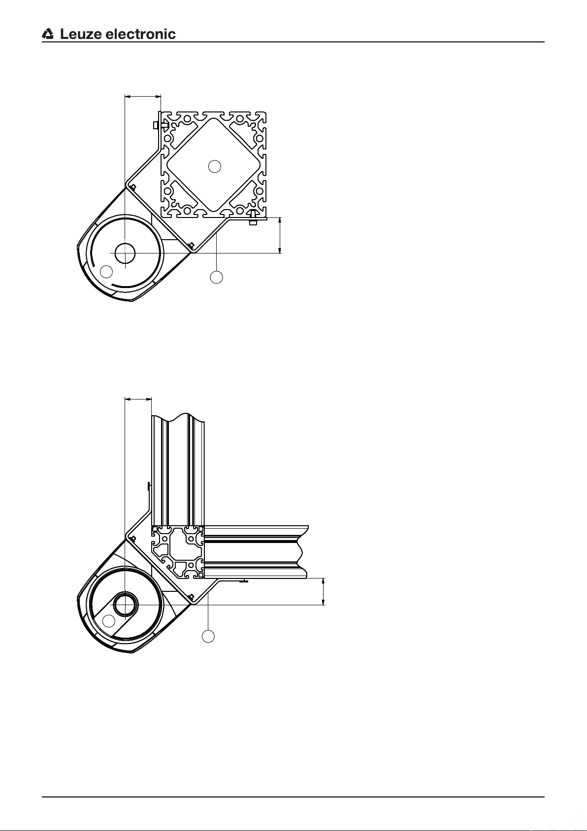
Mounting
5
4
,
6
54,6
1
2
3
1
4
0
40
2
7.1.4
Mounting examples
all dimensions in mm
1 Safety sensor
2 Column
3 BT856M mounting bracket
Fig.7.3: Example: mounting on a post
all dimensions in mm
1 Safety sensor
2 BT840M mounting bracket
Fig.7.4: Example: mounting on a chamfered corner
Leuze electronic RSL 440 59

2 3
1
1 BTF815M mounting bracket (only in combination with the BTU800M mounting system)
2 BTU800M mounting system
3 Safety sensor
Mounting
7.1.5
Fig.7.5: Example: mounting on floor
Information on protective field dimensioning
NOTICE
Protective fields with a radius of less than 200mm (safety sensor short range) are not permitted
and are therefore preset as minimum contour.
Ä Dimension the protective field big enough that the safety sensor's switching signal can stop the danger-
ous movement in good time.
If several protective fields are selected with field pair changeover, this condition applies for all protective fields.
Protective fields with a radius of less than 200mm (safety sensor short range) are not permitted and
are therefore preset as minimum contour.
Ä If you cannot sufficiently dimension a protective field, use additional protective measures, e.g. safety
guards.
Ä Ensure that the protective field cannot be walked behind in the direction of the danger zone.
Ä Observe all delay times, e.g. safety sensor response times, control element response times, braking
times or machine or driverless transportation system stopping times (DTS).
Ä Take changed delay times, which, for example, can be caused by reducing the braking force, into ac-
count.
Ä Observe shadowing effects, e.g. surfaces and areas behind static objects. People in the shadows of
these objects will not be detected by the safety sensor.
Ä Observe the lateral tolerance when dimensioning the protective fields (see chapter 15 "Technical
data").
Ä Do not use cone-shaped protective field contours, as these do not guarantee any protective function.
Ä Take the additional distances required for the application into account.
Handling unmonitored areas
There is an area behind the safety sensor that the safety sensor does not monitor. Unmonitored areas can
also materialize, e.g. if you install a safety sensor on a rounded off vehicle front.
It must not be possible to walk behind unmonitored areas.
Leuze electronic RSL 440 60

1
2 3
1 Safety sensor
3
2
1
1
4 5 4 53
6
2 Protective field
3 Unmonitored area;
Optimum availability at a distance of 50mm to fixed contours
Mounting
Fig.7.6: Unmonitored area
Ä Prevent access to an unmonitored area with screens.
Ä Prevent walking behind by countersinking the safety sensor into the machine contour.
1 Countersinking into the machine contour, min. 100mm
2 Minimum distance above the scanner unit, min. 34mm
3 Protective field
4 Safety sensor
5 Machine
6 Angled physical cover
Leuze electronic RSL 440 61
Fig.7.7: Stepping behind protection by countersinking into the machine contour

Mounting
2 23
4 4
5
1 1
1
2
2
Ä Use a physical cover set at an angle over the safety sensor if you expect that the safety sensor will be
used as a climbing aid or standing surface.
Protective field setup with adjacent safety sensors
The safety sensor has been developed in a way that prevents several safety sensors from interfering with
one another as much as possible. Nevertheless, if several safety sensors are positioned adjacent to each
other, this may result in a reduction in the availability of the safety sensors.
Ä When mounting the safety sensor, avoid glossy surfaces directly behind the optics cover.
Ä Plan for shielding with stationary applications.
The shielding must be at least as high as the safety sensor's optics cover and embedded with the front
housing edge.
If you plan for a shielding that is still within the countersinking in the machine contour, the resolution of
the protective fields must not be impaired at any accessible points.
You require the reciprocal shielding with both horizontal and vertical alignment of the protective fields.
1 Point of operation
2 Safety sensor
3 Machine with countersinking for sensor installation
4 Protective fields
5 Shielding
Fig.7.8: Shielding prevents reciprocal influencing of safety sensors set up beside one another
Ä Install the safety sensors off-set on the height.
1 Minimum distance, min. 100mm
2 Scan level
Fig.7.9: Height offset mounting, parallel alignment
Leuze electronic RSL 440 62

Ä Install the safety sensors with crossed alignment.
11
11
1 Scan level
Fig.7.10: Mounting beside one another, without height offset, crossed alignment
Mounting
1 Scan level
Fig.7.11: Mutually opposing mounting, without height offset, crossed alignment
7.2 Stationary danger zone guarding
The safety sensor takes over the stop-activating and presence-detecting function.
Calculation of safety distanceS for parallel approach to the protective field
S
K [mm/s] = Approach speed for danger zone guarding with approach direction parallel to the protective
T [s] = Total time of the delay, sum from (ta+ti+tm)
t
a
t
i
t
m
C [mm] Additional distance for danger zone guarding with approach reaction
Response times, stopping time of the machine
The safety sensor's rotary mirror rotates on its own axis every 40ms. One revolution is a scan. At least two
consecutive scans must be interrupted so that the safety-related switching outputs switch off. The safety
sensor's minimum response time is therefore 80ms.
If you want to increase the safety sensor's availability in an environment with fine particles, increase the
number of interrupted scans after which the safety-related switching outputs switch off. With each additional scan the response time ta increases by 40ms. With K=1600mm/s the safety distance increases by
64mm per additional scan.
Ä Select a response timeta of at least 120ms or higher.
Ä Determine the machine/system's stopping timetm.
Ä If an increase in the stopping time within the regular test periods is to be expected, take an additional
[mm] = Safety distance
RO
field (resolution up to 90mm): 1600mm/s
[s] = Response time of the protective device
[s] = Response time of the safety relay
[s] = Stopping time of the machine
H=height of the protective field, H
than0, d=resolution of the protective device C=1200mm-0.4×H; H
If data is not available, you can commission Leuze electronic to perform measurements; see chapter 14
"Service and support".
time into account for the machine's stopping timetm.
=minimum installation height permitted, but no smaller
min
=15×(d-50)
min
Leuze electronic RSL 440 63

Additional distanceC for danger zone guarding with approach reaction
S
D
D
S
R
G
D
S
1
2
3
4
You prevent reaching the point of operation by reaching over with the additional distanceC:
H [mm] = Height of protective field above floor (installation height)
C
H
[mm] = 850mm
MIN
[mm] = 1000mm
MAX
The minimum permissible installation height depends on the resolution of the safety sensor:
Tab.7.2: Additional distanceC depending on the resolution of the safety sensor
Mounting
Safety sensor resolution (mm) Minimum permissible installation
height (mm)
Additional distance C (mm)
50 0 1200
60 150 1140
70 300 1080
Application-related additional distances for safety distanceS
The protective field boundaries must be defined so that the calculated safety distance S to the point of operation, extended by the additional distances, is complied with everywhere. Where this is not possible or
does not make sense, you can use hard guards as supplementary measures.
1 Routing machine with free space for sensor protective field in the area under the machine table
2 Safety sensor
3 Protective field contour
4 Warning field contour
S Calculated safety distanceS
D Minimum distanceD (= safety distanceS + additional distanceZSM + Z
R
G
Fig.7.12: Defining the protective field contour for a stationary, horizontal protective field
Largest protective field radius without additional distances, measured from the rotation axis of the rotary
mirror
, where required)
REFL
Leuze electronic RSL 440 64

Mounting
Ä Define the limits of the protective field using the safety distance S without an additional distance.
Ä Determine the biggest protective field radius RG for this protective field.
The biggest protective field radius determines the additional distanceZSM for the system-related measurement error, by which the protective field contour must be enlarged.
The position of the rotary mirror's center point with regard to the housing is provided by the dimensioned drawings.
Tab.7.3: Additional distance ZSM for the protective field contour because of measurement error
Biggest protective field radiusRG without additional distances Additional dis-
tanceZ
SM
< 6.25m 100mm
> 6.25m 120mm
Ä Avoid retro-reflectors at the beam level beyond the protective field boundaries. If this is not possible,
add another additional distanceZ
of 100mm.
REFL
Minimum distanceD to the protective field contour
The minimum distanceD is the distance between point of operation and protective field contour.
D [mm] = Minimum distance between the point of operation and the protective field contour
Z
Z
[mm] = Additional distance for system-related measurement error
SM
[mm] = Additional distance for retro-reflectors
REFL
Ä If the protective field runs up against fixed boundaries, such as walls or machine frames, take a coun-
tersinking into the machine contour of at least the size of the necessary additional distance ZSM, and
Z
where required, into account. With the protective field contour under these conditions, stay about
REFL
50mm away from the machine surface.
Ä If the protective field runs up against hard guards, ensure that the protective field ends under instead of
in front of the hard guards. The width of the lower post must correspond with the size of the required
additional distances.
Ä If all hazards in the fenced off area are covered by the safety sensor and the height of the beam level is
300mm, you can raise the bottom edge of the hard guards from 200 mm to 350 mm in the protective
field range. The protective field reaching to under the hard guards takes over the protective function of
preventing an adult from crawling under in this case.
NOTICE
The beam level of the safety sensor is level with the alphanumerical display.
Ä Prevent obstructions within the calculated protective field boundaries. If this is not possible, implement
protective measures so that the point of operation cannot be reached from out of the shadow of the obstruction.
Leuze electronic RSL 440 65

7.3 Stationary point of operation guarding
The safety sensor takes over the stop-activating and presence-detecting function.
Calculation of safety distanceSRO for access over the vertical protective field
Mounting
S
K [mm/s] = Approach speed for point of operation guarding with approach reaction and normal approach
T [s] = Total time of the delay, sum from (ta+ti+tm)
t
a
t
i
t
m
C
[mm] = Safety distance
RO
direction to the protective field (resolution 14to40mm): 2000mm/s or 1600mm/s, when
SRO>500mm
[s] = Response time of the protective device
[s] = Response time of the safety relay
[s] = Stopping time of the machine
[mm] = Additional distance in which a body part can move towards the protective device before the
RO
protective device triggers
Response times, stopping time of the machine
The safety sensor's rotary mirror rotates on its own axis every 40ms. One revolution is a scan. With each
additional scan the response time ta increases by 40ms. With K=2000mm/s approach speed this corresponds with an increase in the safety distance of 80mm per additional scan. With K=1600mm/s it is
64mm.
Ä Select a response timeta of at least 80ms or higher.
Ä Determine the machine/system's stopping timetm.
If data is not available, you can commission Leuze electronic to perform measurements (see chapter
14 "Service and support").
Ä If an increase in the stopping time within the regular test periods is to be expected, take an additional
time into account for the machine's stopping timetm.
Additional distanceCR0 for finger protection
The required finger protection is ensured here by an additional distance C, which depends on the safety
sensor resolution, in addition to the safety distance.
• Detection of an adult's hand:
• Resolution: 30mm
• Additional distance CRO: 128mm
• Arm detection:
• Resolution: 40mm
• Additional distance CRO: 208mm
Protective field contour and reference contour
With a vertical protective field, you must define at least two sides of the protective field contour as reference contour. The objective is to monitor the position of the protective field with regard to its marginal area.
If the arrangement misaligns and the distance of the safety sensor to the reference surface changes as a
result, switch the safety-related switching outputs off.
Leuze electronic RSL 440 66

Mounting
e
e
S
2
3
4
5
1
1
1 Physical frame for reference contour
2 Reference contour, must cover at least two sides of the protective field
3 Safety sensor
4 Distancee between the reference contour frame and machine opening, recommended: e=150mm
5 Machine opening contour
Fig.7.13: Defining the protective field contour and reference contour, stationary point of operation guarding, verti-
cal protective field
7.4 Stationary access guarding
The vertical protective field used for access guarding only detects people during passage through. After a
person has passed through, a start/restart interlock must ensure that the dangerous movement does not
start again automatically.
S
K [mm/s] = Approach speed for access guarding with approach direction orthogonal to the protective
T [s] = Total time of the delay, sum from (ta+ti+tm)
t
a
t
i
t
m
C
Response times, stopping time of the machine
The safety sensor's rotary mirror rotates on its own axis every 40ms. One revolution is a scan. With each
additional scan the response time ta increases by 40ms. With K=2000mm/s approach speed this corresponds with an increase in the safety distance of 80mm per additional scan. With K=1600mm/s it is
64mm.
Ä Select a response timeta of 80ms or higher.
Ä Determine the machine/system's stopping timetm.
Ä If an increase in the stopping time within the regular test periods is to be expected, take an additional
[mm] = Safety distance
RT
field: 2000mm/s or1600mm/s, when SRT>500mm
[s] = Response time of the protective device, max. 80ms
[s] = Response time of the safety relay
[s] = Stopping time of the machine
[mm] = Additional distance for access guarding with approach reaction with resolutions of
RT
14to40mm, d=resolution of protective device CRT=8×(d-14)mm. Additional distance for
access guarding for resolutions>40mm: CRT=850mm (standard value for arm length)
Never define a value higher than 80ms for ta for access guarding or passage controls. With higher values it can happen that a person might not be detected when passing through the protective field with
an approach speed of 1600mm/s.
If data is not available, you can commission Leuze electronic to perform measurements (see chapter
14 "Service and support").
time into account for the machine's stopping timetm.
Leuze electronic RSL 440 67

Mounting
Additional distanceCRT for finger protection
The required finger protection is ensured here by an additional distance C, which depends on the safety
sensor resolution, in addition to the safety distance.
• Detection of an adult's hand:
• Resolution: 30mm
• Additional distance CRT: 128mm
• Arm detection:
• Resolution: 40mm
• Additional distance CRT: 208mm
Protective field contour and reference contour
With a vertical protective field, you must define at least two sides of the protective field contour as reference contour. The objective is to monitor the position of the protective field with regard to its marginal area.
If the arrangement misaligns and the distance of the safety sensor to the reference surface changes as a
result, switch the safety-related switching outputs off.
Ä When defining the protective field ensure that there are no gaps bigger than 150mm.
Ä When defining the protective field boundaries, specify the sectors that monitor the position of the pro-
tective field as reference contour.
7.5 Mobile danger zone guarding on DTSs
Danger zone guarding protects people and objects that are in rooms in which vehicles move in, e.g. automated guided vehicle systems (DTSs).
A horizontally arranged protective field protects people and objects that are in the vehicle's path and are
detected by the front edge of the protective field.
WARNING
Danger of injury because of insufficient vehicle stopping distance
Ä The operator of the machine must use organizing measures to prevent people from entering
the protective field of the vehicle from the sides or being able to move towards an approaching vehicle.
Ä Only use the safety sensor on vehicles with electrical drive and electrically influenced drive and braking
devices.
Ä Only install the safety sensor on the front of the vehicle.
If you must also guard the reverse travel, you must also install a safety sensor on the rear of the vehicle.
Ä Mount the safety sensor on the vehicle so that there are no unmonitored areas ≥70mm between the
protective field and vehicle front.
Ä Set the mounting height such that the beam level is not more than 200mm above the floor.
A person lying on the floor can therefore be safely detected. This is required by the C standard,
EN1525 "Safety of industrial trucks – Driverless corridor supply vehicles and their systems".
NOTICE
The beam level of the safety sensor is level with the alphanumerical display.
Leuze electronic RSL 440 68
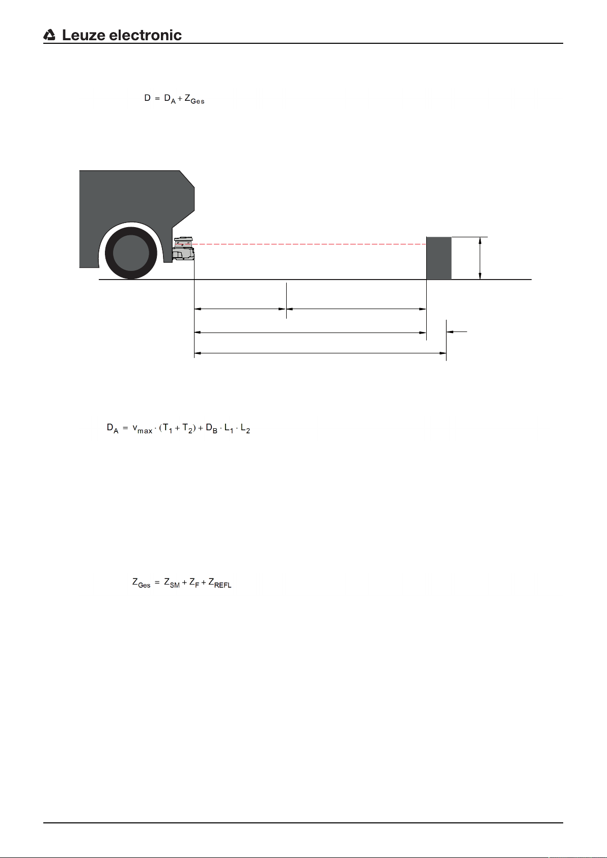
Mounting
D
D · L · L
B
1
2
V · (T +T )
max
1
2
Z
GES
200
D
A
7.5.1
Minimum distanceD
D [mm] = Minimum distance, vehicle front (danger) to protective field front edge
D
Z
[mm] = Stopping distance
A
[mm] = Sum of required additional distances
TOT
Fig.7.14: Mobile danger zone guarding, calculation of required minimum distanceD
Stopping distanceD
D
v
T
T
D
L
L
[mm] = Stopping distance
A
[mm/s] = Maximum vehicle speed
max
[s] = Response time of the safety sensor
1
[s] = Response time of the FTS
2
[mm] = Braking distance with v
B
[---] = Factor for brake wear
1
[---] = -Factor for problematic floor conditions, e.g. dirt, wet conditions
2
A
and maximum vehicle load
max
Additional distancesZ
Z
Z
Z
Z
[mm] = Total of the required additional distances
tot
[mm] = Additional distance for system-related measurement error, see chapter 7.2 "Stationary dan-
SM
ger zone guarding"
[mm] = Additional distance required with lack of floor space H
F
[mm] = Additional distance required with retro-reflectors beyond the protective field boundaries;
REFL
Z
REFL
=100mm
F
The additional distanceZSM is always required. Its size depends on the biggest radius RG from the safety
sensor mirror's rotary axis to the protective field boundary without Z
. The position of the rotary mirror axis
Tot
depends on the installation situation.
Leuze electronic RSL 440 69

Mounting
20
40
60
80
100
120
20
40
60
80
100
120
140
160
Z
F
H
F
Z
F
H
F
Z
GES
D
F
R
F
L
D
A
Z
GES
Z
GES
R
G
The additional distanceZF is required if the vehicle does not have enough free floor spaceHF and there is
therefore no space under the vehicle or the safety sensor for the tips of the feet. You determine the additional distanceZF according to the following diagram:
7.5.2
Fig.7.15: Diagram for determining the additional distanceZF with lack of floor spaceH
F
If wheels are mounted near the side wall, always add an additional distanceZF > 150mm.
Protective field dimensions
D Minimum distance, vehicle front (danger) to protective field front edge
D
A
Z
TOT
F
L
F
R
R
G
Fig.7.16: Mobile danger zone guarding, dimensions for horizontal protective field
Ä Select 70mm resolution.
Stopping distance
Total required additional distances to the front and for both sides
Distance from safety sensor center to left vehicle edge
Distance from safety sensor center to right vehicle edge
Biggest radius in the protective field without Z
for determining the additional distance Z
TOT
SM
Ä Set the protective field length so that the response time until braking and the braking distance, including
factors for wear and tear and floor conditions, and any necessary additional distances are taken into
account.
Ä Arrange the protective field symmetrically with reference to the vehicle width, even if the safety sensor
is not arranged centered.
Ä Configure an upstream warning field that reduces the vehicle's speed.
A full brake with a subsequent interruption of the protective field is then executed moderately and is
less demanding on the vehicle's drives.
Dimension the minimum distance D for the maximum speed as if the speed reduction initiated by the
warning field had not happened.
Leuze electronic RSL 440 70

Ä Take the required free space for lateral protrude protective fields under the roller conveyors along the
transportation path into account.
Ä If you have to expect angular deviations of the vehicle during the travel, plan an additional tolerance
area to guarantee undisturbed travel operation.
7.6 Mobile side guarding on DTSs
WARNING
Danger of injury because of insufficient vehicle stopping distance
Ä The operator of the machine must use organizing measures to ensure that people cannot
enter the vehicle's protective field from the side.
Ä For mobile vertical protective fields use a resolution of at least 150mm.
Ä Position the protective field edges in the travel direction in accordance with the front protective field
edge of the horizontal protective field.
Ä Ensure that the response times of all components of the switch-off circuit are the same or balance the
response times with different protective field dimensioning.
Ä Set the vertical protective fields at a slight angle so that the lower protective field edges protrude over
the vehicle width by the amount of the additional distances, ZSM, ZF and Z
ter 7.5.2 "Protective field dimensions".
Mounting
where required; see chap-
REFL
7.7 Mounting accessories
7.7.1
Mounting system
Using the mounting system you can adjust the safety sensor horizontally and vertically by ±10degrees
when mounting.
Fig.7.17: BTU800M mounting system
NOTICE
Floor mounting only with mounting system BTU800M
Ä The mounting system BTU800M must be used in the case of installation using the mounting
bracket for floor mounting.
Ä Install the wall mount or mounting bracket for floor mounting on the system side.
Ä Mount the mounting system on the wall mount or on the mounting bracket for floor mounting.
Ä Attach the safety sensor to the mounting system.
Tightening the screws fixes the safety sensor in position.
Ä Align the safety sensor using the integrated electronic spirit level.
Leuze electronic RSL 440 71

Mounting
1
1
2
3 3
4
7.7.2
Loop guard
The loop guard for the optics cover prevents damage to the safety sensor caused by light contact with foreign objects.
NOTICE
The loop guard can only be used together with the mounting system BTU800M.
1 BTF815M mounting bracket for floor mounting (only with BTU800M mounting system)
2 BTU800M mounting system
3 Loop guard
4 Safety sensor
Fig.7.18: Loop guard
Ä Attach the safety sensor to the mounting system.
Ä Engage the loop guard for the optics cover from above into the mounting system.
Leuze electronic RSL 440 72

8 Electrical connection
WARNING
Faulty electrical connection or improper function selection may result in serious injury!
Ä Only allow competent persons to perform the electrical connection.
Ä For access guarding, activate the start/restart interlock and make certain that it cannot be
unlocked from within the danger zone.
Ä Select the functions so that the safety sensor can be used as intended (see chapter 2.1 "In-
tended use").
Ä Select the safety-relevant functions for the safety sensor (see chapter 5.2 "Function modes
of safety sensor").
Ä Always loop both safety-related switching outputs OSSD1 and OSSD2 into the work circuit
of the machine.
Ä Signal outputs must not be used for switching safety-relevant signals.
NOTICE
Laying cables!
Ä Lay all connection cables and signal lines within the electrical installation space or perma-
nently in cable ducts.
Ä Lay the cables and lines so that they are protected against external damages.
Ä For further information: see EN ISO 13849-2, Table D.4.
Electrical connection
NOTICE
Observe the maximum cable length!
Observe the maximum cable lengths as a function of operating voltage and load current (see
chapter 8.3 "Connection unit CU429").
NOTICE
Observe when wiring with terminals and connectors!
In the case of wiring that continues beyond the device or during repairs to connectors, the user
must ensure that cables or conductors that have defectively disconnected cannot result in contact with other signals.
Ä Use suitable terminals.
Ä Use heat-shrink tubing, wire-end sleeves or similar.
8.1 Electrical supply
see chapter 15.1 "General specifications".
Functional earth
NOTICE
Always connect the housing of the safety sensor to functional earth or ground!
Ä The housing of the safety sensor must always be connected to earth (functional earth) or
machine/vehicle ground.
Ä If the safety sensor is attached to a non-conductive material (e.g. a concrete wall), the hous-
ing of the safety sensor must be earthed.
• Factory recommendation: Functional earth via a ground strap/braid (low impedance for RF).
Connection points for self-tapping screws used for the ground connection are provided and labeled on
the bottom of the connection unit (see chapter 8.3 "Connection unit CU429").
Leuze electronic RSL 440 73

• Functional grounding via the shield of the connection cable.
For grounding, the shield of the connection cable in the switch cabinet must be connected to earth or
machine/vehicle ground.
8.2 Interfaces
The safety sensor has two interfaces:
• Interface for connection with the control system
• Interface for communication with PC or laptop
Tab.8.1: Interfaces
Interface Type Function
Control Connection cable, 29-wire • Power supply
Electrical connection
NOTICE
Make sure that potential equalization is provided!
Ä If the housing of the safety sensor or the mounting bracket – despite being mounted on a
non-conductive material – is connected to metallic parts (even temporarily), you must ensure
that the appropriate potential equalization is provided between the switch cabinet and housing potential; e.g. by grounding the Ethernet connection.
• Switching lines and signal lines
8.2.1
Communication M12 – RJ45 Configuration interface and data interface:
• Parameter configuration
• Protective field definition and warning field definition
• Data transmission and measurement value transmission
• Diagnosis
The control cable is permanently attached to the connection unit. A protection cap on the connection unit
protects the communication interface when no PC is connected.
Connection cable, control
The safety sensor is equipped with a 29-wire connection cable.
Tab.8.2: Connection cable, control
Core color Signal Description
White RES1 Start/restart input, protective functionA
Acknowledgment
Brown 24V Supply voltage
Green EA1 Contactor monitoring OSSDA
Alternatively: State signaling, configurable
Yellow A1 Output signal
State signaling, configurable
Gray OSSDA1 Safety-related switching output, protective functionA
Pink OSSDA2 Safety-related switching output, protective functionA
Blue 0V (GND) Supply voltage ground
Red MELD Output signal
State signaling, configurable
Leuze electronic RSL 440 74
Electrical connection
10
6
3
7
11
16
12
18
17
23
22
27
26
30
21
29
25
28
24
20
15
19
13
14
8
9
4
5
1
2
Core color Signal Description
Black F1 5 function inputs for field pair changeover, protective functionA
Violet F2
Gray/pink F3
Red/blue F4
White/Green F5
Brown/Green SE1 Linkage input (E-Stop, OSSD – external device)
White/Yellow SE2 Linkage input (E-Stop, OSSD – external device)
Yellow/Brown A2 Output signal
White/Gray A3 Output signal
Gray/Brown A4 Output signal
White/Pink EA2 Contactor monitoring OSSDB
Field pair changeover with 100 field pairs (A1.x) – 2nd position
Field pair changeover with multi configuration (A1.x) within one
bank
State signaling, configurable
State signaling, configurable
State signaling, configurable
Alternatively: State signaling, configurable
8.2.2
Pink/Brown EA3 Input/output signal, configurable
White/Blue EA4 Input/output signal, configurable
Brown/Blue F6 5 function inputs for field pair changeover, protective functionB
White/Red F7
Brown/Red F8
White/Black F9
Brown/Black F10
Gray/Green RES2 Start/restart input, protective functionB
Yellow/Gray OSSDB1 Safety-related switching output, protective functionB
Pink/Green OSSDB2 Safety-related switching output, protective functionB
Connection cable with M30 connector
The safety sensor is equipped with a 30-pin M30 connector.
Field pair changeover with 100 field pairs (Ay.1) – 1st position
Bank changeover with multi configuration (Ay.1)
Acknowledgment
Fig.8.1: Pin assignment for M30 connector, 30-pin
Leuze electronic RSL 440 75

Electrical connection
Tab.8.3: Pin assignment
Pin Core color Signal Description
1 White RES1 Start/restart input
protective functionA
acknowledgment
2 Brown 24V Supply voltage
3 Green EA1 Contactor monitoring OSSDA
Alternatively: State signaling, configurable
4 Gray OSSDA1 Safety-related switching output
protective functionA
5 Pink OSSDA2 Safety-related switching output
protective functionA
6 Red MELD Output signal
state signaling, configurable
7 Yellow A1 Output signal
state signaling, configurable
8 Black F1 5 function inputs for field pair changeover
9 Violet F2
protective functionA
Field pair changeover with 100 field pairs (A1.x) –
10 Gray/pink F3
11 Blue/red F4
12 White/Green F5
2nd position
Field pair changeover with multi configuration (A1.x)
within one bank
13 Brown/Green SE1 Linkage input
(E-Stop, OSSD – external device)
14 White/Yellow SE2 Linkage input
(E-Stop, OSSD – external device)
15 Yellow/Brown A2 Output signal
state signaling, configurable
16 White/Gray A3 Output signal
state signaling, configurable
17 Gray/Brown A4 Output signal
state signaling, configurable
18 White/Pink EA2 Contactor monitoring OSSDB
Alternatively: State signaling, configurable
19 Pink/Brown EA3 Input/output signal, configurable
20 White/Blue EA4 Input/output signal, configurable
21 Brown/Blue F6 5 function inputs for field pair changeover
22 White/Red F7
protective functionB
Field pair changeover with 100 field pairs (Ay.1) –
23 Brown/Red F8
24 White/Black F9
1st position
Bank changeover with multi configuration (Ay.1)
25 Brown/Black F10
26 Yellow/Gray OSSDB1 Safety-related switching output
protective functionB
27 Pink/Green OSSDB2 Safety-related switching output
protective functionB
28 --- --- ---
29 Blue 0V (GND) Supply voltage ground
Leuze electronic RSL 440 76

Pin Core color Signal Description
43
12
M5 2x
2
1
30 Gray/Green RES2 Start/restart input
protective functionB
acknowledgment
Electrical connection
8.2.3
Connector
Shield FE Functional earth, connection cable shield
housing
Pin assignment of M12 Ethernet interface (communication) ( D-coded)
The safety sensor is equipped with a 4-pin M12 connector.
Fig.8.2: Pin assignment of the Ethernet interface
Tab.8.4: Pin assignment of the Ethernet interface
PIN Signal Description
1 TD+ Data communication, transmission
2 RD+ Data communication, transmission
3 TD- Data communication, reception
4 RD- Data communication, reception
FE GND/shield Functional earth, communication cable shield. The shield of the inter-
connection cable is on the thread of the M12 plug. The thread is part of
the metallic housing. The housing is at the same potential as functional
earth.
8.3 Connection unit CU429
1 Connection cable, connection to the machine
2 M12 socket, D-coded, Ethernet communication connection
M5 Connection for functional earth with M5x10 self-cutting/self-tapping (gas tightness) and ground strap
Fig.8.3: Connection unit CU429
Leuze electronic RSL 440 77

Electrical connection
1
2
3
4
5
6
7
8
9
10
Cable lengths as a function of operating voltage and load current
The maximum cable length is determined by voltage drops on the supply and signal lines.
The following conditions apply for the necessary operating voltage UB at the input terminals of the connection unit:
• UB must be greater than the permissible nominal voltage limit of 16.8V.
NOTICE
The recommended operating voltage is 19V!
Leuzeelectronic recommends an operating voltage UB of 19V at the input terminals of the connection unit.
Ä The operating voltage should not be allowed to drop below the recommended value if possi-
ble.
• The necessary operating voltage UB must also ensure the function of the downstream devices.
• Once the operating voltage UB has been determined, check whether the resulting signal voltages
are sufficient for the downstream devices.
• Take into account the voltage drops in the safety sensor – up to 3.2V – and on the signal wiring.
1 Operating voltage [V]
2 Cable length [m]
3 ILoad = 0A
4 ILoad = 250mA
5 ILoad = 500mA
6 ILoad = 750mA
7 ILoad = 1A
8 ILoad = 1.25A
9 ILoad = 1.5A
10 ILoad = 1.65A
Fig.8.4: Diagram for estimating the voltage drop on the supply line
• Maximum load current: 1.65A with RSL400 cable
1mm2/AWG18 for supply and 0.14mm2/AWG26 for signals
NOTICE
Cable length and cable resistance with OSSD linkage!
When using the OSSD linkage function, observe the specifications of the upstream device for
the cable length and for the maximum permissible cable resistance (see chapter 5.13.2 "Linkage
of electronic safety-related switching outputs").
Leuze electronic RSL 440 78
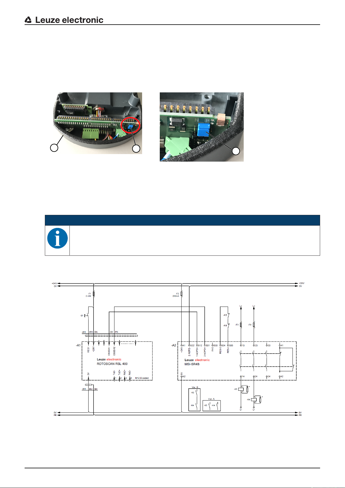
Electrical connection
1
2
1
PNP/NPN changeover
The PNP/NPN changeover for signal inputs F1…F10, RES1, RES2 is performed via a jumper on the connection unit. The reference potential for the signal inputs is set via the jumper:
• P: reference potential +24V
• N: reference potential 0V (GND)
1 Jumper
2 Connection unit
Fig.8.5: Jumper for PNP/NPN changeover
NOTICE
PNP/NPN changeover occurs simultaneously for signals F1…F10, RES1, RES2.
8.4 Circuit diagram example
* Spark extinction circuit, suitable spark extinction provided
Fig.8.6: RSL440 with MSI-SR4B safety relay
Leuze electronic RSL 440 79

9 Configuring the safety sensor
To start up the safety sensor in your application, the safety sensor must be individually adapted using the
software. All configuration data is defined using the configuration and diagnostics software.
General procedure for configuring safety sensor
Ä Assessing the risk
• The system has been determined and its boundaries defined.
• The safety sensor has been selected as the safety component.
• The type of guarding has been determined (danger zone guarding, point of operation guarding, access
guarding).
Ä Calculating safety distance
Shape and size of the protective and warning fields
Ä Configuring the safety sensor
• Configuration and diagnostics software (see chapter 4 "Configuration and diagnostic software SensorStudio")
• Determine the configuration project (see chapter 9.3 "Determine the configuration project")
• Configure the protective function (see chapter 9.4 "Configuring protective function")
Ä Checking function (see chapter 11 "Testing")
Configuring the safety sensor
9.1 Defining safety configuration
WARNING
Serious accidents caused by incorrect safety configuration!
The protective function of the safety sensor is only ensured if the safety sensor is correctly configured for the intended application.
Ä Allow only competent persons to perform safety configuration.
Ä Select the safety configuration so that the safety sensor can be used as intended (see chap-
ter 2.1 "Intended use").
Ä Select the protective field dimensions and contours according to the safety distance calcu-
lated for the application (see chapter 7.1.1 "Calculation of safety distanceS").
Ä Select the parameters of the safety configuration according to your risk analysis.
Ä After start-up, check the function of the safety sensor (see chapter 11.1 "Before the initial
start-up and following modifications").
WARNING
Additional protection against manipulation when the monitoring time is increased!
If the monitoring time is increased to above 5s or if manipulation protection is deactivated, the
system operator must introduce other measures to prevent manipulation.
Ä For example, make sure that the distance range in which manipulation is possible cannot be
accessed by personnel under normal operating conditions.
Leuze electronic RSL 440 80

Configuring the safety sensor
NOTICE
OSSDs will switch off if no reflection signals are being measured!
If the safety sensor is unable to measure any reflection signals in a continuous scanning angle
of ≥90° for a long period of time, the safety-related switching outputs switch off. In certain application types (e.g. in buildings with extremely large distances), the safety sensor may not be able
to measure any reflection signals. For such application types, it is possible to set or deactivate
the monitoring times.
Ä In the CONFIGURATION menu, click the Other option.
ð The OTHER dialog box opens.
Ä In the PROTECTION AGAINST MANIPULATION dialog box, define the monitoring time ac-
cording to your specific conditions.
ð If the parking position is active, there will be no manipulation monitoring.
Prerequisites:
• The safety sensor is mounted (see chapter 7 "Mounting") and connected (see chapter 8 "Electrical connection") correctly.
• Dangerous process is switched off, outputs of the safety sensor are disconnected, and the system is
protected against being switched back on.
• The size of the protective field is determined on the basis of the mounting location, the calculated
safety distances and additional distances.
• The start/restart operating mode required by the application has been determined.
• The conditions for field pair changeover, if required, have been determined.
• The configuration and diagnostics software for the safety sensor is installed on the PC (see chapter 4.2
"Installing software").
NOTICE
Many safety-relevant parameters are preset for each application in the configuration and diagnostics software. Use these preset values where possible.
Procedure
All configuration data is defined using the configuration and diagnostics software.
To configure the safety sensor, proceed as follows:
Ä Connect the PC to the safety sensor
Ä Start the software
• Set up communication
• Determine the configuration project
Ä Configure the protective function using the project wizard
• Protective/warning field configuration
• Resolution and response time
• Start-up behavior
• Contactor monitoring
• E-stop linkage
• Field pair changeover
• Configuration of the signal outputs
Ä Save configuration project
Ä Transferring a configuration to the safety sensor
Ä Create a record document for the device configuration and protective field dimensioning. The document
must be signed by the person responsible for the configuration.
To document the configuration, you can create a PDF file of the safety configuration or save the configuration and settings in an *.xml file.
Leuze electronic RSL 440 81

NOTICE
The configuration data is stored in the connection unit of the safety sensor and is therefore also
available after replacement or repair of the scanner unit. The configuration data only needs to
be transferred again if changes are made to the configuration.
9.2 Connecting safety sensor to PC
Configuring the safety sensor
9.2.1
9.2.2
Connection via Ethernet cable
Connect the Ethernet cable to the PC or to the network; see the document "Quick Start Guide RSL400".
NOTICE
The TCP/IP protocol is used for communication via Ethernet.
NOTICE
In addition to configuration, you can also use the Ethernet interface to forward measurement
data in real-time (process data) to another computer, e.g. for vehicle navigation. This process
data cannot be used for safety-relevant purposes.
Connection via Bluetooth
NOTICE
No process data is transferred in the case of connection via Bluetooth.
Prerequisites: Bluetooth communication of the safety sensor has been activated (see chapter 9.2.3 "Communication between safety sensor and PC")
Ä Activate the Bluetooth interface on the PC.
Ä Select the safety sensor as the device for the Bluetooth connection.
9.2.3
NOTICE
Distance between safety sensor and PC
The possible distance between safety sensor and PC depends on the quality of the Bluetooth
adapter that is used.
USB Bluetooth adapters with external rod antenna enable a larger operating range.
Communication between safety sensor and PC
The following communication settings are active when the safety sensor is delivered:
LAN
• DHCP: Obtain IP address automatically
Bluetooth
• Bluetooth module activated
• Device scan activated
You can change the communication settings on the PC using the configuration and diagnostics software in
order to, for example, assign a permanent IP address to the safety sensor in your network.
Ä Start the configuration and diagnostics software on your PC.
ð The mode selection of the Project Wizard is displayed.
ð If the mode selection is not shown, click the [Project Wizard] button ( ) in the menu bar of the soft-
ware to start the project wizard.
Leuze electronic RSL 440 82

Configuring the safety sensor
Ä Select the configuration mode and click [Next].
ð The Project Wizard displays the device selection list containing the configurable safety sensors.
Ä Select the safety sensor from the device selection list and click [Next].
ð The initial screen for the configuration project is displayed together with information for identification of
the selected safety sensor.
Ä In the initial screen, click the SETTINGS tab.
ð The SETTINGS menu opens.
Assign permanent IP address
Ä Select the menu command Communication > LAN.
Ä In the DHCP dialog box, deactivate the Obtain IP address automatically checkbox.
Ä In the CONNECTION SETTINGS dialog box, enter the IP address information.
Activating/deactivating the Bluetooth interface
Ä Select the menu command Communication > Bluetooth.
Ä Activate/deactivate communication with the safety sensor via the Bluetooth interface using the Activate
Bluetooth module checkbox. If the Bluetooth module is deactivated, communication with the safety sensor via the Bluetooth interface is not possible.
Ä Activate/deactivate the Bluetooth device scan using the Activate device scan checkbox. If the device
scan is deactivated, the safety sensor will not be found during the Bluetooth device scan. To allow communication via the Bluetooth interface, you must enter the device identification of the safety sensor
manually.
9.3 Determine the configuration project
Ä Start the configuration and diagnostics software on your PC.
ð The mode selection of the Project Wizard is displayed.
ð If the mode selection is not shown, click the [Project Wizard] button ( ) in the menu bar of the soft-
ware to start the project wizard.
NOTICE
During installation of the software, a user admin (without password query) is created so that you
can start the software without user identification. If other users are registered (Tools > User
management in the FDT frame menu), you must log in at the software with a user name and
password.
This setting allows you to connect to the safety sensor and to read out, upload, enter or change
the safety configuration and all settings using the RSL400 device DTM. The password for the
safety sensor only needs to be entered (i.e. the access level only needs to be changed) when
the changes are downloaded to the safety sensor (see chapter 4.5.1 "Selecting access level").
Ä Select the configuration mode and click [Next].
ð The Project Wizard shows the list of configurable safety sensors.
NOTICE
You can use a prepared configuration project as a template and make changes to it. To do so,
select the configuration mode Open a stored project file.
If you want to load the configuration project currently stored in the safety sensor to the PC, select the configuration mode Device selection with device scan and establishment of connection
(online).
Ä Select the safety sensor in the Sensor list and click OK.
Alternatively, you can select the safety sensor by entering the part number or by specifying the sensor
range and the sensor type.
ð The device manager (DTM) of the safety sensor shows the initial screen for the configuration project.
Leuze electronic RSL 440 83

Configuring the safety sensor
1
1 Configuration Wizard
Fig.9.1: Safety configuration using Configuration Wizard
NOTICE
The device manager (DTM) starts without querying the access level of the user. During communication with the safety sensor, the safety sensor does however query the access level of the
user. To change the access levels, see chapter 9.9 "Selecting access level".
9.4 Configuring protective function
Prerequisites: The safety distance, additional distances and protective field dimensions and contours have
been determined according to the mounting position (see chapter 7.1.1 "Calculation of safety distanceS").
Ä In the initial screen, click the CONFIGURATION tab.
ð The CONFIGURATION menu opens with the options:
• Administration
• OSSDs
If the OSSDs option is selected in the CONFIGURATION menu, the Protective function A option is
displayed, if the One protective function function mode is selected. In the Two protective functions
function mode, the options Protective function A and Protective function B are displayed.
• Changeover order
The Changeover order option is only displayed if more than one protective/warning field pair is created (see chapter 9.4.4 "Creating and configuring protective/warning field pairs").
• Outputs
• Other
Leuze electronic RSL 440 84

Configuring the safety sensor
9.4.1
9.4.2
9.4.3
Creating simple safety configuration
To create a safety configuration for simple commissioning, you must first perform five configuration steps to
access the editor used for defining the contours of the protective and warning fields.
By clicking [Next], you can proceed to the next configuration step without selecting the corresponding option in the CONFIGURATION menu.
If you make changes to the default settings in a configuration step, first click the [Confirm] button and then
[Next].
Ä Administration
Ä OSSDs
Ä Protective function A
Ä Bank A1
Ä Outputs
Entering administration parameters
Ä In the CONFIGURATION menu, click the Administration option.
ð The ADMINISTRATION dialog box opens.
Ä In the input fields, enter the device data and the project data for the configuration project.
Activating protective function and contactor monitoring
Ä In the CONFIGURATION menu, click the OSSDs option.
ð The OSSDs dialog box opens.
Ä In the FUNCTION MODE list, select the protective function of the safety sensor.
ð The Protective functionA option is shown in the CONFIGURATION menu.
ð The Protective functionB option is shown in the CONFIGURATION menu if Two protective functions
was selected in the FUNCTION MODE list.
NOTICE
The changeover-capable protective/warning field pairs for the selected protective function are
defined in configuration banks.
Ä In the Switch off delay time input field, select the internal safe time delay for switching off the OSSD-B
outputs if One protective function was selected in the FUNCTION MODE list.
Ä In the CONTACTOR MONITORING list, activate the contactor monitoring of the safety sensor:
• EDM OSSD A
• EDM OSSD B
• E-Stop
• OSSD linkage
NOTICE
The activated contactor monitoring (EDM) is assigned to indication signal outputs EA1 and/or
EA2. These signal outputs are thus disabled for the configuration of the signal outputs.
Ä Click the [Confirm] button.
Leuze electronic RSL 440 85

Configuring the safety sensor
9.4.4
Creating and configuring protective/warning field pairs
The changeover-capable protective/warning field pairs for the selected protective function are defined in
configuration banks. The configuration banks are shown in the navigation tree of the configuration menu as
"Bank", e.g. Bank A1.
Configuring protective/warning field pairs for tow protective functions
NOTICE
Configuration of the protective and warning field pairs is described for the One protective function function mode (Protective functionA). If you have selected Two protective functions as the
function mode, you must also configure the banks and field pairs for Protective functionB following the described procedure.
Creating banks
Ä In the CONFIGURATION menu, click the Protective functionA option.
ð The PROTECTIVE FUNCTIONA dialog box opens.
Ä Enter the description of the protective function in the input field.
Ä In the CONFIGURATION menu, right-click the Protective functionA option.
Select Add configuration bank.
ð The Add bank dialog box opens.
Ä In the Bank list, select the number of the bank and click the [Add] button.
When you have added all banks for the protective function, click [Close].
ð The Bank[x] option is shown for each added bank under Protective functionA in the CONFIGURA-
TION menu.
Configuring banks
The resolution for hand, leg or body detection, the response time and start-up behavior of the safety sensor
and the field pair changeover for the protective/warning field pairs are configured via the banks.
NOTICE
For resolution, response time and DTS speed, select the values that you used for calculating the
safety distances and additional distances for the application assigned to the configuration bank.
Ä In the CONFIGURATION menu, select the bank the configuration of which you want to define.
ð The RESOLUTION, RESPONSE TIME, START-UP BEHAVIOR and EXTENDED OUTPUT SIGNALS
dialog boxes are displayed.
Ä In the RESOLUTION dialog box, enter the resolution and, if applicable, the maximum speed of a driver-
less transportation system (DTS) in the input fields.
NOTICE
If in the Resolution and Max. DTS speed input fields you select values >0, the application usually used for the bank is displayed in the Application field, e.g. Point of operation guarding.
For access guarding, point of operation guarding and danger zone guarding, you must select
Max. DTS speed=0!
Ä In the RESPONSE TIME dialog box, select the response time of the safety sensor.
Ä In the START-UP BEHAVIOR dialog box, select the start-up behavior and the restart time of the safety
sensor.
NOTICE
Configuration of the start-up behavior is only implemented if the corresponding electrical signal
connections exist; see chapter 8 "Electrical connection".
Ä In the EXTENDED OUTPUT SIGNALS dialog box, activate the definition of output signals.
Ä Click the [Confirm] button.
Ä Configure all other banks of the protective function following the described procedure.
Leuze electronic RSL 440 86

Configuring the safety sensor
2
3
1
Create protective and warning fields
A field pair consists of one protective field and one warning field.
Ä In the CONFIGURATION menu, right-click the Bank1 option under Protective function_A
Select Add field pair.
ð The Add field pair dialog box opens.
Ä In the Field pair list, select the number of the field pair and click the [Add] button. When you have
added all field pairs for the bank, click [Close].
ð The added field pairs are shown in the CONFIGURATION menu as an option under Bank1 under Pro-
tective function_A. The Parameters option is displayed for each field pair.
Ä Add the field pairs for the other banks of Protective functionA if one protective function with multiple
configuration banks has been selected.
ð The added field pairs are shown in the CONFIGURATION menu under Bank[x] under Protective func-
tionA.
Configure protective and warning fields
Defining contours and boundaries for protective field and warning field
1 Toolbar of field editor
2 Display of field coordinates
3 Structure of safety configuration
Fig.9.2: Field editor with toolbar for field definition
Ä In the CONFIGURATION menu, click the field pair the protective and warning fields of which you want
to define.
Ä Click the button and define the contours and boundaries of the protective field.
NOTICE
Determine protective field size!
The protective field size is determined by the calculated safety distances and additional distances that you determined for the application assigned to the configuration bank.
Ä Click the button and define the contours and boundaries of the warning field.
NOTICE
By right-clicking the field pair in the CONFIGURATION menu, you can calculate an autocontour
for the protective or warning field.
You can determine the display options for the field editor in the menu SETTINGS > Field editor
display options (see chapter 4.5.6 "SETTINGS").
Ä Configure all other field pairs of the configuration bank following the described procedure.
Leuze electronic RSL 440 87
Configuring the safety sensor
9.4.5
Configuring field pair monitoring
Ä In the CONFIGURATION menu, click the Parameters option of the field pair the protective and warning
fields of which you have defined.
Ä Select the monitoring mode for the field pair in the Field pair monitoring list.
9.5 Defining permissible field pair changeovers
If monitoring of field pair changeover is activated, you can define the permissible sequence of field pair
changeovers.
Determining changeover mode
Ä In the CONFIGURATION menu, select the protective functionA or protective functionB option.
Ä In the dialog box MODE FOR FIELD PAIR ACTIVATION AND CHANGEOVER, select the field pair ac-
tivation, the mode for field pair changeover and, if required, the changeover time.
Field pair activation
Changeover mode
Fixed selection of one field
pair
Selection by signal inputs
Fixed changeover moment
Description
Changeover of two field pairs
Changeover of 10 field pairs (see chapter 5.7.3 "Changeover of ten field
pairs in changeover mode Fixed changeover moment")
When the changeover time has expired, the system changes over to the field
pair which at this time has a permanent and valid assignment. Field pair
changeover signals issued during the changeover time are ignored.
The inputs F1 - F5 are active.
The inputs F6 - F10 are active.
Selection by signal inputs
Overlapped monitoring
Ä Click the [Confirm] button.
Determining changeover order
Ä In the CONFIGURATION menu, select the Changeover order option.
ð The CHANGEOVER ORDER dialog box opens.
Ä In the MONITORING OF FIELD PAIR CHANGEOVER dialog box, activate the Monitoring option.
Ä In the MONITORING OF FIELD PAIR CHANGEOVER dialog box, define the sequence of field pair
changeovers according to your conditions.
Ä Click the [Confirm] button.
Changeover of 5 field pairs (see chapter 5.7.2 "Changeover of five field pairs
in changeover mode Overlapped monitoring")
Both field pairs are monitored during the changeover time.
The inputs F1 - F5 are active.
The inputs F6 - F10 are active.
9.6 Configuring signal outputs
You can define which indication signals are transmitted to the individual indication signal connections.
Ä In the CONFIGURATION menu, select the Outputs option.
The OUTPUTS dialog box opens.
Ä For each usable connection, select the function group and the function of the indication signal.
Ä Click the [Confirm] button.
NOTICE
All signal outputs are high active, i.e. logical 1 or +24V DC with an active signal.
Leuze electronic RSL 440 88

9.7 Saving configuration
To save the changed configuration loaded in the software, you can transfer the configuration and settings
to the safety sensor or save them in a file on the PC.
Saving safety configuration as PDF file
Ä In the CONFIGURATION menu, click the [Create PDF file of safety configuration] button.
Ä Determine the storage location and the file name for the safety configuration.
Ä Click [Save].
ð The safety configuration is saved as a PDF file.
Saving configuration and settings as file
Ä In the CONFIGURATION menu or in the SETTINGS menu, click the [Save configuration and settings to
file] button.
Ä Determine the storage location and the name of the configuration file.
Ä Click [Save].
ð The configuration and settings are saved in the file format *.xml.
Saving configuration project as file
Ä In the menu bar of the FDT frame menu, click the button.
Alternatively, select the menu command File > Save.
Ä Determine the storage location and the name of the configuration project file.
Ä Click [Save].
Configuring the safety sensor
9.8 Transferring configuration project to safety sensor
The changes that you have made to the configuration only become effective when the changed configuration project file is transferred to the safety sensor.
Prerequisites:
• The software and safety sensor are connected.
• The changed configuration project has been loaded in the software.
• The individual password for the access level Engineer is available.
• Only users with the access level Engineer can transfer configuration data to the safety sensor. To
change the access level, see chapter 9.9 "Selecting access level".
• If no individual password has been defined for the access level Engineer, use the preset default
password (safety).
NOTICE
Alternatively, you can transfer a configuration project saved as a file on the PC directly to the
safety sensor.
Ä In the menu bar of the FDT frame menu, click the [download arrow] button. Alternatively: In the FDT
menu bar, select Device > Download parameters.
ð The software asks for the access level and the password.
Ä Select the access level Engineer and enter the preset default password (safety) or the defined individ-
ual password.
Confirm with [OK].
Leuze electronic RSL 440 89

Configuring the safety sensor
Ä Before downloading the safety configuration, check whether you are connected to the correct safety
sensor.
Confirm the displayed safety notice with [Yes].
Fig.9.3: Check before safety configuration is downloaded
The software transfers the data of the configuration project to the safety sensor.
After successful transfer, the safety sensor immediately enters safety mode, i.e. the safety-related switching outputs switch on if all conditions are fulfilled.
• The configuration data is saved in the connection unit of the safety sensor.
• A copy of the safety configuration is saved in the scanner unit of the safety sensor.
If, due to a device swap-out, the scanner unit is attached to a brand new, unconfigured connection unit,
the safety configuration is transferred from the scanner unit to the connection unit.
NOTICE
Observe the safety notices regarding changes to the configuration!
Transferring the safety configuration from the scanner unit to the connection unit corresponds to
reconfiguration of the system consisting of scanner unit and connection unit.
Ä Observe the relevant safety notices regarding changes to the configuration (see chapter 9.1
"Defining safety configuration").
Ä Check the displayed signature.
Leuze electronic RSL 440 90

Configuring the safety sensor
Ä Confirm successful transfer of the safety configuration to the safety sensor with [OK].
The safety configuration has only been successfully transferred to the safety sensor when the confirmation dialog is displayed during the download.
Fig.9.4: Confirmation: safety configuration downloaded
NOTICE
The safety-related switching outputs will already have switched on if all conditions are fulfilled.
ð The software has saved the configuration project in the safety sensor.
9.9 Selecting access level
Using the device manager (DTM) you can change the access level of the user, if necessary (see chapter
5.1 "Authorization concept of safety sensor").
Ä Click in the DTM menu bar on the Change access levelbutton ( ).
ð The Change access level dialog box opens.
Ä In the Authorization list, select the item Engineer, Expert or Observer and enter the default password
or the password defined for the individual user (see chapter 4.5.6 "SETTINGS").
• Default password for Engineer: safety
• Default password for Expert: comdiag
Ä Confirm with [OK].
9.10 Reset safety configuration
The device manager (DTM) can be used to reset the safety configuration to the default configuration (one
protective function, no restart).
Ä In the DTM menu bar, click the [Reset safety configuration] button.
ð Users with the access level Engineer can additionally transfer the changed safety configuration to the
safety sensor (see chapter 9.8 "Transferring configuration project to safety sensor").
Leuze electronic RSL 440 91

10 Starting up the device
WARNING
Improper use of the safety sensor may result in serious injury!
Ä Make certain that the entire device and the integration of the optoelectronic protective de-
vice was inspected by competent and instructed persons.
Ä Make certain that a dangerous process can only be started while the safety sensor is
switched on
Prerequisites:
• Safety sensor mounted (see chapter 7 "Mounting") and connected (see chapter 8 "Electrical connection") correctly
• Operating personnel were instructed in proper use
• Dangerous process is switched off, outputs of the safety sensor are disconnected, and the system is
protected against being switched back on
Ä After start-up, check the function of the safety sensor (see chapter 11.1 "Before the initial start-up and
following modifications").
10.1 Switching on
Requirements for the supply voltage (power supply unit):
• Reliable mains separation is ensured.
• Current reserve of at least 3A is available.
Ä Switch on the safety sensor.
Starting up the device
10.2 Aligning the safety sensor
NOTICE
Faulty or incorrect alignment may result in an operating fault!
Ä The alignment performed during start-up should only be performed by qualified personnel.
Ä Observe the data sheets and mounting instructions of the individual components.
To simplify alignment during start-up, the safety sensors of the RSL400 series have an integrated electronic spirit level.
Ä Align the safety sensor using the integrated electronic spirit level.
10.3 Unlocking start/restart interlock
WARNING
Premature unlocking of the start/restart interlock may result in serious injury!
If the start/restart interlock is unlocked, the system can start up automatically.
Ä Before unlocking the start/restart interlock, make certain that no people are in the danger
zone.
The responsible person can restore the ON state of the safety sensor following process interruptions (due
to triggering of protective function, failure of the voltage supply).
Ä Unlock the start/restart interlock using the reset button.
The safety-related switching outputs are only enabled if you hold down the reset button for between
0.12s and 4s.
Leuze electronic RSL 440 92

10.4 Shutting down
Temporarily shutting down the machine with the safety sensor
When you shut down the machine with the safety sensor temporarily, you do not have to observe any more
steps. The safety sensor saves the configuration and starts again with the switch-on with this configuration.
Shutting down safety sensor and removing from machine
When you shut down the safety sensor and store it away for a later use, you must reset the safety sensor
to the factory settings.
Ä Reset the safety sensor to the factory settings using the software.
In the device manager (DTM) of the safety sensor, select the CONFIGURATION tab.
Click the [Reset safety configuration] button.
10.5 Restarting
Restarting the machine with the safety sensor
If you have only shut down the system with the safety sensor temporarily and are restarting the system
without any changes, you can restart the safety sensor with the configuration that applied with the shutdown. The configuration remains saved in the safety sensor.
Ä Perform a function test (see chapter 11.3 "Periodically by the operator").
Starting up the device
Starting up machine with safety sensor after modification or reconfiguration
If you have performed significant changes on the machine or have reconfigured the safety sensor, the
safety sensor must be checked as with the initial start-up.
Ä Test the safety sensor (see chapter 11.1 "Before the initial start-up and following modifications").
10.6 Starting up replacement scanner unit
The replacement scanner unit and the original scanner unit must be the same with regard to the following
points:
• Scanner unit type in accordance with name plate or downward compatible with previous scanner unit
with greater range and greater function range
• Mounting on the existing connection unit
Mounting and aligning replacement scanner unit
Ä Mount the replacement scanner unit on the connection unit instead of the original scanner unit (see
chapter 13.1 "Changing scanner unit").
NOTICE
Realignment of safety sensor not necessary!
Realignment of the safety sensor is not necessary since the replacement scanner unit is
mounted on the existing, aligned connection unit.
Transferring configuration to replacement scanner unit
The configuration stored in the connection unit is automatically transferred to the replacement scanner unit.
WARNING
Malfunctioning of safety sensor due to incorrect configuration!
Ä The safety sensor configuration stored in the connection unit can only be adopted without
changes if the replacement scanner unit and the original scanner unit are downward compatible with respect to range and performance class.
The replacement scanner unit will reject an invalid configuration.
Ä Change the configuration parameters of the safety sensor using the configuration and diag-
nostic software according to the performance class of the replacement scanner unit.
Ä Change the configuration parameters of the safety sensor using the configuration and diag-
nostic software according to the operating range of the replacement scanner unit.
Leuze electronic RSL 440 93

Starting up the device
Transferring configuration with the PC
If the range and/or performance class of the replacement scanner unit is not compatible with the original
scanner unit, you must adapt the configuration of the safety sensor to the replacement scanner unit.
Ä Connect the safety sensor's Ethernet communication interface with the PC.
Ä Configure the safety sensor according to the range and performance class of the replacement scanner
unit (see chapter 9 "Configuring the safety sensor").
Ä Transfer the configuration to the safety sensor with the replacement scanner unit.
ð The alphanumerical display confirms successful transfer of the configuration.
The replacement scanner unit is not compatible with the connection unit if the safety sensor displays a
fault.
Checking replacement scanner unit
The check performed on the replacement device depends on whether you automatically adopted the configuration from the connection unit or whether you transferred the changed configuration to the safety sensor.
Ä If you adopted the configuration from the connection unit, check the safety sensor using the checklist
for the daily test.
Ä If you transferred a new configuration to the safety sensor, check the safety sensor according to the
routine for initial start-up (see chapter 11.1.1 "Checklist for integrator – to be performed prior to the initial start-up and following modifications").
Leuze electronic RSL 440 94

11 Testing
NOTICE
Ä Safety sensors must be replaced at the end of their mission time (see chapter 15 "Technical
data").
Ä Always exchange entire safety sensors.
Ä For the tests, observe, if necessary, nationally applicable regulations.
Ä Document all tests in a comprehensible manner and include the configuration of the safety
sensor along with the data for the safety- and minimum distances in the documentation.
11.1 Before the initial start-up and following modifications
WARNING
Unpredictable machine behavior during initial start-up may result in serious injury!
Ä Make certain that there are no people in the danger zone.
Ä Before they begin work, train the operators on their respective tasks. The training is the responsibility of
the operating company.
Ä Attach notes regarding daily testing in the respective national language of the operator on the machine
in a highly visible location, e.g. by printing out the corresponding chapter (see chapter 11.3 "Periodically
by the operator").
Ä Test the electrical function and installation according to this document.
Acc. to IECTS62046 and national regulations (e.g. EU directive2009/104/EC), tests are to be performed
by competent persons in the following situations:
• Prior to initial commissioning
• Following modifications to the machine
• After longer machine downtime
• Following retrofitting or new configuration of the machine
Ä As preparation, check the most important criteria for the safety sensor according to the following check-
list (see chapter 11.1.1 "Checklist for integrator – to be performed prior to the initial start-up and following modifications"). Completing the checklist does not replace testing by a competent person!
Not until proper function of the safety sensor is ascertained may it be integrated in the control circuit of the
system.
Testing
11.1.1
Leuze electronic RSL 440 95
Checklist for integrator – to be performed prior to the initial start-up and following modifications
NOTICE
Completing the checklist does not replace testing by a competent person!
Ä If you answer one of the items on the check list with no, the machine must no longer be op-
erated (see table below).
Ä IEC/TS62046 contains additional recommendations on testing protective devices.
Tab.11.1: Checklist for integrator – to be performed prior to the initial start-up and following modifications
Check: Yes No n.a.
not applicable
Is the safety sensor operated acc. to the specific environmental conditions that
are to be maintained (see chapter 15 "Technical data")?
Is the safety sensor correctly aligned and are all fastening screws and connectors secure?
Are safety sensor, connection cables, connectors, protection caps and command devices undamaged and without any sign of manipulation?

Testing
Check: Yes No n.a.
not applicable
Does the safety sensor satisfy the required safety level (PL, SIL, category)?
Are the safety-related switching outputs (OSSDs) integrated in the downstream
machine control acc. to the required safety category?
Are switching elements that are controlled by the safety sensor monitored according to the required safety level (PL, SIL, category) (e.g., contactors through
EDM)?
Are all points of operation near the safety sensor accessible only through the
protective field of the safety sensor?
Are the necessary additional protective devices in the immediate surroundings
(e.g., safety guard) properly mounted and secured against tampering?
If it is possible to be present undetected between the safety sensor and point
of operation: is an assigned start/restart interlock functional?
Is the command device for unlocking the start/restart interlock mounted in such
a way that it cannot be reached from within the danger zone and so that the
complete danger zone can be seen from the installation location?
Has the maximum stopping time of the machine been measured and documented?
Is the required safety distance maintained?
Does interruption with a test object intended for this purpose cause the dangerous movement(s) to stop?
Is the safety sensor effective during the entire dangerous movement(s)?
Is the safety sensor effective in all relevant operating modes of the machine?
Is start-up of dangerous movements reliably prevented if the protective field is
interrupted with a test object intended for this purpose?
Was the sensor detection capacity successfully tested (see chapter 11.3.1
"Checklist – periodically by the operator")?
Were distances to reflective surfaces taken into account during configuration
and no reflection bypasses subsequently detected?
Are notices for regular testing of the safety sensor legible to the operator and
are they located in a highly visible location?
Are changes to the safety function (e.g. protective field changeover) not easy
to achieve through tampering?
Are settings that could result in an unsafe state possible only by means of key,
password or tool?
Are there incentives that pose stimulus for tampering?
Were the operators instructed prior to starting work?
11.2 To be performed periodically by competent persons
The reliable interaction of safety sensor and machine must be periodically tested by competent persons in
order to detect changes to the machine or impermissible tampering with the safety sensor.
Acc. to IEC/TS 62046 and national regulations (e.g., EU directive 2009/104/EC), tests of elements which
are subject to wear must be performed by competent persons at regular intervals. Testing intervals may be
regulated by nationally applicable regulations (recommendation acc. to IEC/TS62046: 6months).
Ä Have all tests performed by competent persons.
Ä Observe the nationally applicable regulations and the time periods specified therein.
Ä As preparation, observe the checklist (see chapter 11.1 "Before the initial start-up and following modifi-
cations").
Leuze electronic RSL 440 96
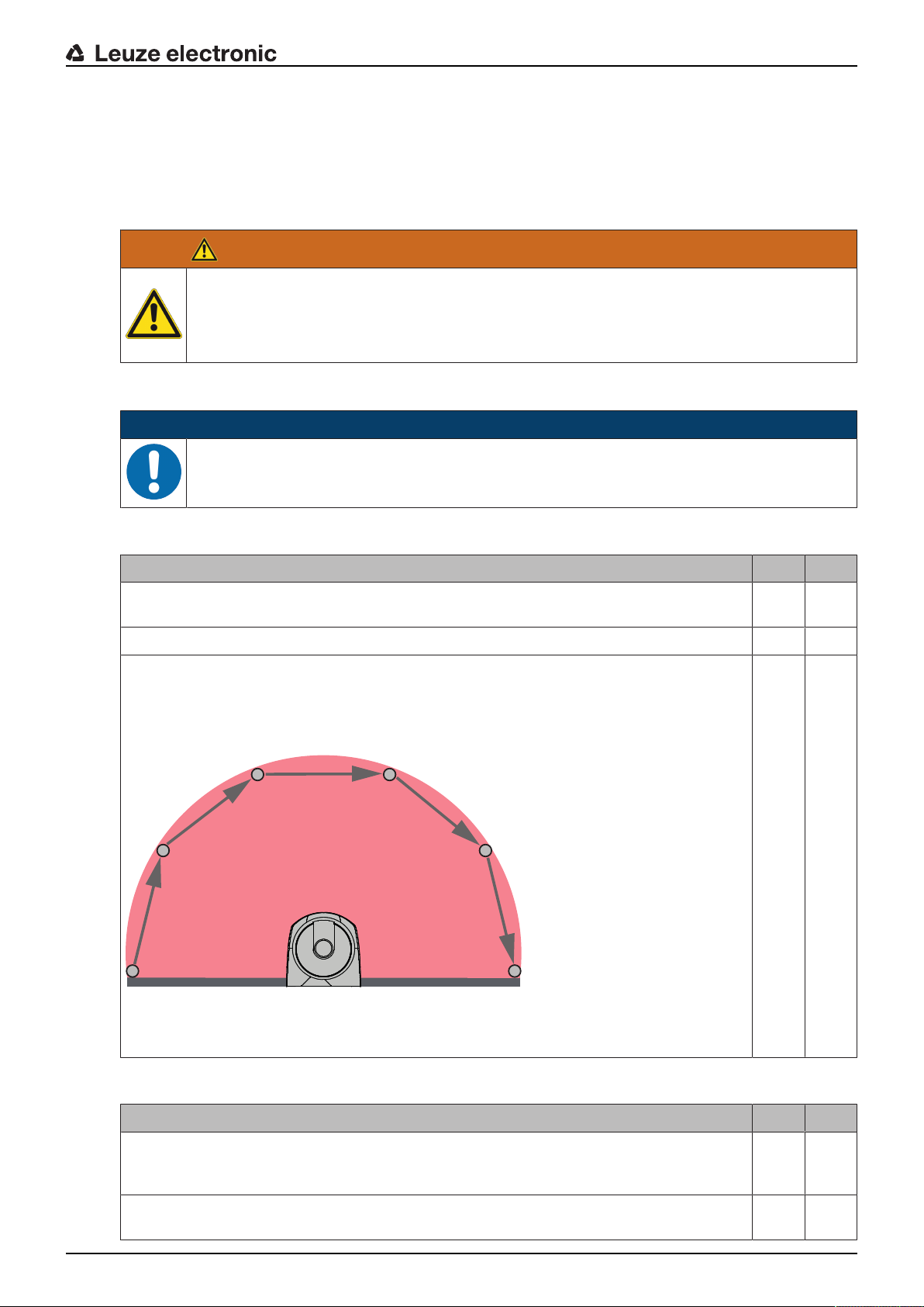
11.3 Periodically by the operator
The function of the safety sensor must be checked regularly (e.g., daily, on shift change, monthly or in an
even longer cycle) according to the following checklist. The frequency of the checks is determined by
means of the risk analysis performed by the operating company.
Due to complex machines and processes, it may be necessary under certain circumstances to check some
points at longer time intervals. Observe the classification in "Test at least" and "Test when possible".
WARNING
Unpredictable machine behavior during the test may result in serious injury!
Ä Make certain that there are no people in the danger zone.
Ä Before they begin work, train the operators on their respective tasks and provide suitable
test objects and an appropriate test instruction.
Testing
11.3.1
Checklist – periodically by the operator
NOTICE
Ä If you answer one of the items on the check list with no, the machine must no longer be op-
erated (see chapter 11.1.1 "Checklist for integrator – to be performed prior to the initial startup and following modifications").
Tab.11.2: Checklist – regular function test by trained operators/persons
Test at least: Yes No
Are safety sensor and connectors securely mounted and free of obvious signs of damage,
changes or tampering?
Were obvious changes made to access or entry possibilities?
Test the effectiveness of the safety sensor:
1. The LED1 and LED6 on the safety sensor must illuminate green (see chapter 3.3
"Display elements").
2. Interrupt the protective field using a suitable opaque test object (see figure).
Checking the protective field function with test rod
Do the LED1 and LED6 on the safety sensor illuminate constantly red while the protective field is interrupted?
Tab.11.3: Checklist – regular function test by trained operators/persons
When possible, test during running operation: Yes No
Protective device with approach function: during machine operation, the protective field is
interrupted with the test object – are the obviously dangerous machine parts stopped without noticeable delay?
Protective device with presence detection: the protective field is interrupted with the test
object – does this prevent operation of the obviously dangerous machine parts?
Leuze electronic RSL 440 97

12 Diagnostics and troubleshooting
12.1 What to do in case of failure?
After switching the safety sensor on, the display elements assist in checking the correct functionality and in
faultfinding (see chapter 3.3 "Display elements").
In case of failure, you can determine the fault from the LED displays and read a message from the display.
With the error message you can determine the cause of the error and initiate measures to rectify it.
NOTICE
If the safety sensor responds with an error display, you will often be able to eliminate the
cause yourself!
Ä Switch off the machine and leave it switched off.
Ä Analyze the cause of the fault using the diagnostics displays and rectify the fault.
Ä If you are unable to rectify the fault, contact the Leuzeelectronic branch responsible for you
or call the Leuzeelectronic customer service (see chapter 14 "Service and support").
12.2 Diagnostics displays
The diagnostics displays consist of one letter plus four numbers, divided into classes consisting of letters
and the first number.
Diagnostics classes:
• I (Information)
• No OSSD switch-off
• Unhindered operation possible
Diagnostics and troubleshooting
• U (Usage)
Application error
• E (External)
External fault
• F (Failure)
internal device error
• OSSD switch-off
• Self test unsuccessful
• Hardware error
• P (Parameter)
Inconsistency in configuration
Tab.12.1: Diagnostics displays in order of ascending ID number
DiagnosticIDDiagnostic message Measure
U0370 Input level at the electrical inputs is unclear. Check the wiring of the safety sensor.
P0409 Safety configuration is not compatible: un-
known bank switchover.
P0410 Safety configuration is not compatible: un-
known output signals.
Swap out the safety sensor or change the
configuration. The type of safety sensor must
be the same as the type stored in the connection unit or in the Sensor Studio software.
Swap out the safety sensor or change the
configuration. The type of safety sensor must
be the same as the type stored in the connection unit or in the Sensor Studio software.
P0413 Safety configuration is not compatible: un-
known inputs SE1 and SE2.
Leuze electronic RSL 440 98
Swap out the safety sensor or change the
configuration. The type of safety sensor must
be the same as the type stored in the connection unit or in the Sensor Studio software.

DiagnosticIDDiagnostic message Measure
Diagnostics and troubleshooting
P0414 Safety configuration is not compatible: un-
known EDM inputs.
P0415 Safety configuration is not compatible: un-
known field pair monitoring mode.
P0416 Safety configuration is not compatible: un-
known field pair monitoring parameters.
P0417 Safety configuration is not compatible: un-
known field pair monitoring mode.
P0419 Safety configuration is not compatible: un-
known monitoring parameter for the
changeover order.
P0420 Safety configuration is not compatible: un-
known monitoring mode of the field pair
changeover.
Swap out the safety sensor or change the
configuration. The type of safety sensor must
be the same as the type stored in the connection unit or in the Sensor Studio software.
Swap out the safety sensor or change the
configuration. The type of safety sensor must
be the same as the type stored in the connection unit or in the Sensor Studio software.
Swap out the safety sensor or change the
configuration. The type of safety sensor must
be the same as the type stored in the connection unit or in the Sensor Studio software.
Swap out the safety sensor or change the
configuration. The type of safety sensor must
be the same as the type stored in the connection unit or in the Sensor Studio software.
Swap out the safety sensor or change the
configuration. The type of safety sensor must
be the same as the type stored in the connection unit or in the Sensor Studio software.
Swap out the safety sensor or change the
configuration. The type of safety sensor must
be the same as the type stored in the connection unit or in the Sensor Studio software.
P0421 Safety configuration is not compatible: un-
known parameter for field pair changeover
monitoring.
P0422 Safety configuration is not compatible: un-
known field pair selection mode.
P0423 Safety configuration is not compatible: un-
known field pair selection parameter.
P0424 Safety configuration is not compatible: un-
known parameter for manipulation monitoring.
P0425 Safety configuration is not compatible: un-
known configuration of the output signals.
P0426 Safety configuration is not compatible: un-
known resolution.
Swap out the safety sensor or change the
configuration. The type of safety sensor must
be the same as the type stored in the connection unit or in the Sensor Studio software.
Swap out the safety sensor or change the
configuration. The type of safety sensor must
be the same as the type stored in the connection unit or in the Sensor Studio software.
Swap out the safety sensor or change the
configuration. The type of safety sensor must
be the same as the type stored in the connection unit or in the Sensor Studio software.
Swap out the safety sensor or change the
configuration. The type of safety sensor must
be the same as the type stored in the connection unit or in the Sensor Studio software.
Swap out the safety sensor or change the
configuration. The type of safety sensor must
be the same as the type stored in the connection unit or in the Sensor Studio software.
Swap out the safety sensor or change the
configuration. The type of safety sensor must
be the same as the type stored in the connection unit or in the Sensor Studio software.
P0427 Safety configuration is not compatible: un-
known parameter.
Swap out the safety sensor or change the
configuration. The type of safety sensor must
be the same as the type stored in the connection unit or in the Sensor Studio software.
Leuze electronic RSL 440 99

DiagnosticIDDiagnostic message Measure
Diagnostics and troubleshooting
P0429 Safety configuration is not compatible: un-
known start/restart mode.
Swap out the safety sensor or change the
configuration. The type of safety sensor must
be the same as the type stored in the connection unit or in the Sensor Studio software.
P0430 Safety configuration is not compatible: un-
known start mode.
Swap out the safety sensor or change the
configuration. The type of safety sensor must
be the same as the type stored in the connection unit or in the Sensor Studio software.
P0431 Safety configuration is not compatible: un-
known restart mode.
Swap out the safety sensor or change the
configuration. The type of safety sensor must
be the same as the type stored in the connection unit or in the Sensor Studio software.
P0432 Safety configuration is not compatible: un-
known OSSD stop mode.
Swap out the safety sensor or change the
configuration. The type of safety sensor must
be the same as the type stored in the connection unit or in the Sensor Studio software.
U0573 EDM fault at system start. Check the wiring of the downstream relays
and that they are functioning correctly.
U0574 Switching fault, EDM at OSSDA: external
relay does not switch off.
U0575 Switching fault, EDM at OSSDA: external
relay does not switch on.
Check the wiring of the downstream relays
and that they are functioning correctly.
Check the wiring of the downstream relays
and that they are functioning correctly.
U0576 Switching fault, EDM at OSSDB: external
relay does not switch off.
U0577 Switching fault, EDM at OSSDB: external
relay does not switch on.
U0580 Switching fault at inputs SE1 and SE2; ex-
ternal safety device does not switch in accordance with the specifications.
U0582 Field pair changeover is not performed in
accordance with the specifications configured in the safety sensor: overlap time too
long.
U0583 Field pair changeover is not performed in
accordance with the specifications configured in the safety sensor: no signal for field
pair activation.
U0584 Field pair changeover is not performed in
accordance with the specifications configured in the safety sensor: changeover time
exceeded.
U0585 Field pair changeover is not performed in
accordance with the specifications configured in the safety sensor: changeover order
not observed.
Check the wiring of the downstream relays
and that they are functioning correctly.
Check the wiring of the downstream relays
and that they are functioning correctly.
Check the wiring of the external safety device
and that the parameter settings in the configuration are correct.
Check the changeover times of function inputs
F1toF10 or the parameter settings in the
configuration.
Check the wiring and the changeover times of
function inputs F1toF10.
Check the changeover times of function inputs
F1toF10 or the parameter settings in the
configuration.
Check the wiring of function inputs F1toF10
and that the parameter settings in the configuration are correct.
U0792 Field pair changeover without release. Check the release signal for field pair
changeover or change the safety configuration.
U0793 Field pair changeover without request. Check the request signal for field pair
changeover or change the safety configuration.
U0849 Field pair changeover not permitted. Check the wiring of the field pair inputs.
Leuze electronic RSL 440 100
 Loading...