

Page 1
rotoScan ROD4plus / ROD4-08plus
Software and Protocol Description
GB 01-02/08 50107322
TECHNICAL DESCRIPTION
Page 2

Table of contents
1 General information........................................................................................................... 3
1.1 On the 'RODplussoft' program ............................................................................................. 3
1.2 Explanation of symbols ........................................................................................................ 3
1.3 Contact address................................................................................................................... 3
2 Hardware and software Installation ................................................................................. 4
2.1 Hardware ............................................................................................................................. 4
2.2 Software............................................................................................................................... 4
2.2.1 System requirements..................................................................................................................... 4
2.2.2 Installation...................................................................................................................................... 4
3 First steps - sample application .......................................................................................5
3.1 Establishing a connection between PC and ROD4…plus ................................................... 5
3.2 Starting the program ............................................................................................................6
3.3 Adjusting the interface for parameterization ........................................................................ 7
3.4 Selecting the Interface for Process Data on the PC ............................................................ 7
3.4.1 Configuring the Ethernet interface of the ROD4…plus.................................................................. 7
3.4.2 Configuring serial interface Y4 of the ROD4…plus .......................................................................8
3.5 Configuring the measurement data protocol of the ROD4…plus......................................... 9
3.5.1 Settings for the ROD4-compatible binary protocol ........................................................................9
3.5.2 Settings for the ASCII Remote protocol......................................................................................... 9
3.6 Displaying the measurement contour ................................................................................ 10
3.7 Configuring measurement segments ................................................................................. 11
3.7.1 Configuring measurement segments for the ROD4-compatible binary protocol ......................... 12
3.7.2 Configuring measurement segments for the ASCII Remote protocol.......................................... 13
4 Menu description .............................................................................................................16
4.1 Menu bar............................................................................................................................ 17
4.1.1 File ............................................................................................................................................... 17
4.1.2 Configuration ...............................................................................................................................17
4.1.3 Settings........................................................................................................................................ 17
4.1.4 Question mark ’?’......................................................................................................................... 18
4.2 Configuration/measurement box........................................................................................ 19
4.2.1 Communication............................................................................................................................ 19
4.2.2 Protocol........................................................................................................................................ 21
4.2.3 Measurement contour.................................................................................................................. 25
4.3 Toolbox and Process Data docking windows .................................................................... 26
4.3.1 Toolbox ........................................................................................................................................ 26
4.3.2 Process data................................................................................................................................ 27
Leuze electronic RODplussoft - Software and protocol description 1
Page 3

Table of contents
5 ROD4-compatible binary protocol.................................................................................. 28
5.1 Protocol structure............................................................................................................... 28
5.1.1 Start..............................................................................................................................................29
5.1.2 Operation .....................................................................................................................................29
5.1.3 Option 1........................................................................................................................................29
5.1.4 Option 2........................................................................................................................................30
5.1.5 Option 3........................................................................................................................................30
5.1.6 Scan number................................................................................................................................30
5.1.7 Angular resolution ........................................................................................................................31
5.1.8 Start angle....................................................................................................................................31
5.1.9 Stop angle ....................................................................................................................................31
5.1.10 Distance measurement value.......................................................................................................32
5.1.11 Check byte ...................................................................................................................................32
5.1.12 End...............................................................................................................................................32
6 ASCII-Remote protocol.................................................................................................... 33
6.1 Online commands ..............................................................................................................33
6.1.1 General 'Online' Commands ........................................................................................................34
6.1.2 Online commands for configuration of the measurement function...............................................35
6.1.3 Online commands for measurement function control...................................................................37
6.2 Measurement data protocol ...............................................................................................38
7 Appendix........................................................................................................................... 39
7.1 Terms and abbreviations ROD4…plus software................................................................ 39
2 RODplussoft - Software and protocol description Leuze electronic
Page 4
1 General information
1.1 On the 'RODplussoft' program
RODplussoft is used for the configuration of the measurement functions of the rotoscan
ROD4…plus via a PC with Microsoft
The software offers the following options:
• Interface configuration of the ROD4…plus
• Measurement data visualisation
• Configuration of measurement segments
• Filtering data output
• Output of extreme values
The measurement data are transferred via the interfaces Y2 or Y4 as selected. You can
select the protocol best suited to your measurement task in each case. The following options
are available:
• ROD4-compatible binary protocol, for fast measurement data transfer. A detailed
protocol description may be found in chapter 5.
• ASCII Remote for extended, flexible measurement data transfer and remote control
operation. In this operating mode, the ROD4…plus reacts to commands from the control. A detailed protocol description may be found in chapter 6.
1.2 Explanation of symbols
The symbols used in this description are explained below.
Attention!
This symbol appears before text passages which must absolutely be observed. Failure to
heed this information may lead to injuries to personnel or damage to the equipment.
®
Windows 2000/XP operating systems.
General information
Notice!
This symbol indicates text passages containing important information.
ª
This symbol asks you to carry out an action.
The Courier font indicates terms contained in the software interface of RODplussoft.
1.3 Contact address
Leuze electronic GmbH + Co.
In der Braike 1, Postfach 1111
73277 Owen/Teck, Germany
Phone +49 (0) 7021/573 0
Fax +49 (0) 7021/573 199
http://www.leuze.com
Leuze electronic RODplussoft - Software and protocol description 3
TNT 35/7-24V
Page 5

Hardware and software Installation
2 Hardware and software Installation
2.1 Hardware
ª
Install the rotoscan ROD4…plus as described in the 'Electrical Connection' chapter of the
Technical description ROD4plus.
2.2 Software
2.2.1 System requirements
The PC used should meet the following requirements:
2.2.2 Installation
The RODplussoft configuration software can be found on the supplied CD. To install, follow
the instructions in the respective readme files, which can likewise be found on the supplied
CD.
You can also download the respective, latest version of RODplussoft from www.leuze.de:
Download -> identify -> Optical distance measuring and positioning.
Unzip the ZIP file supplied into a suitable folder on your hard disk.
ª
ª
®
•Intel
processor at Pentium® level or faster (or compatible models, e.g. AMD®)
• At least 512 MB RAM
•CD-ROM drive
• Hard disk with at least 150 MB available memory.
• RS 232 interface for scanner configuration
• Ethernet interface or, alternatively, RS 232 / RS 422 for measurement data transfer
•Microsoft
•Microsoft
Start the installation by double-clicking on the setup.exe file.
Follow the instructions of the installation routine.
®
Windows 2000/XP SP2
®
.NET Framework 2.0 SP1
Notice!
Before installing RODplussoft, ensure that Microsoft
installed on your computer.
4 RODplussoft - Software and protocol description Leuze electronic
®
.NET Framework 2.0 SP1 or later is
Page 6

First steps - sample application
3 First steps - sample application
This chapter explains the configuration of the ROD4…plus using a sample application. We
assume the following measurement task:
• data transfer via Ethernet
• ROD4-compatible binary protocol
• definition of a measurement segment
• measurement data filtering
• output of
• status information on the ROD4…plus
• measurement data in Cartesian coordinate display
• minimum and maximum values
3.1 Establishing a connection between PC and ROD4…plus
To configure the ROD4…plus using RODplussoft or RODsoft
Connect interface Y3 of the ROD4…plus to an unused COM port of your PC. Use the
ª
KB-ROD4plus cable available as an accessory.
If you want to display the measurement data on the PC, or if you want to use the ASCII
Remote protocol for remote control:
Also connect interface Y2 of the ROD4…plus to a free network port on the same network
ª
as your PC or connect interface Y4 of the ROD4…plus to another free COM port on your
PC.
Beginning with version 1.10, RODplussoft offers the option of configuring the ROD4…plus
via the same interface as is used to transfer measurement data.
This facilitates the following procedure:
• Configuration of the Ethernet interface of the ROD4…plus prior to the mechanical
installation at the installation site. At the installation site, there may be difficulties in
attaching the cable between Y3 and the COM port of the PC due to the installation situation.
• Subsequent selection of Y2 as interface for configuration.
• Mechanical installation of the ROD4…plus at the installation site.
• Configuration of the ROD4…plus via the Ethernet interface.
TNT 35/7-24V
Attention!
Ensure that the connectors for the interfaces Y1, Y2 and Y4 are wired correctly. An incorrect
wiring of the Y1 or Y4 interfaces on the rotoScan ROD4…plus may result in severe device
damage that may be beyond repair.
Notice!
Before starting RODplussoft, switch on the power supply of the ROD4…plus. Otherwise no
data can be received from the device. You can, however, define parameters and save them
to the hard disk or evaluate previously saved data without connecting the ROD4…plus to
the PC.
Leuze electronic RODplussoft - Software and protocol description 5
Page 7
First steps - sample application
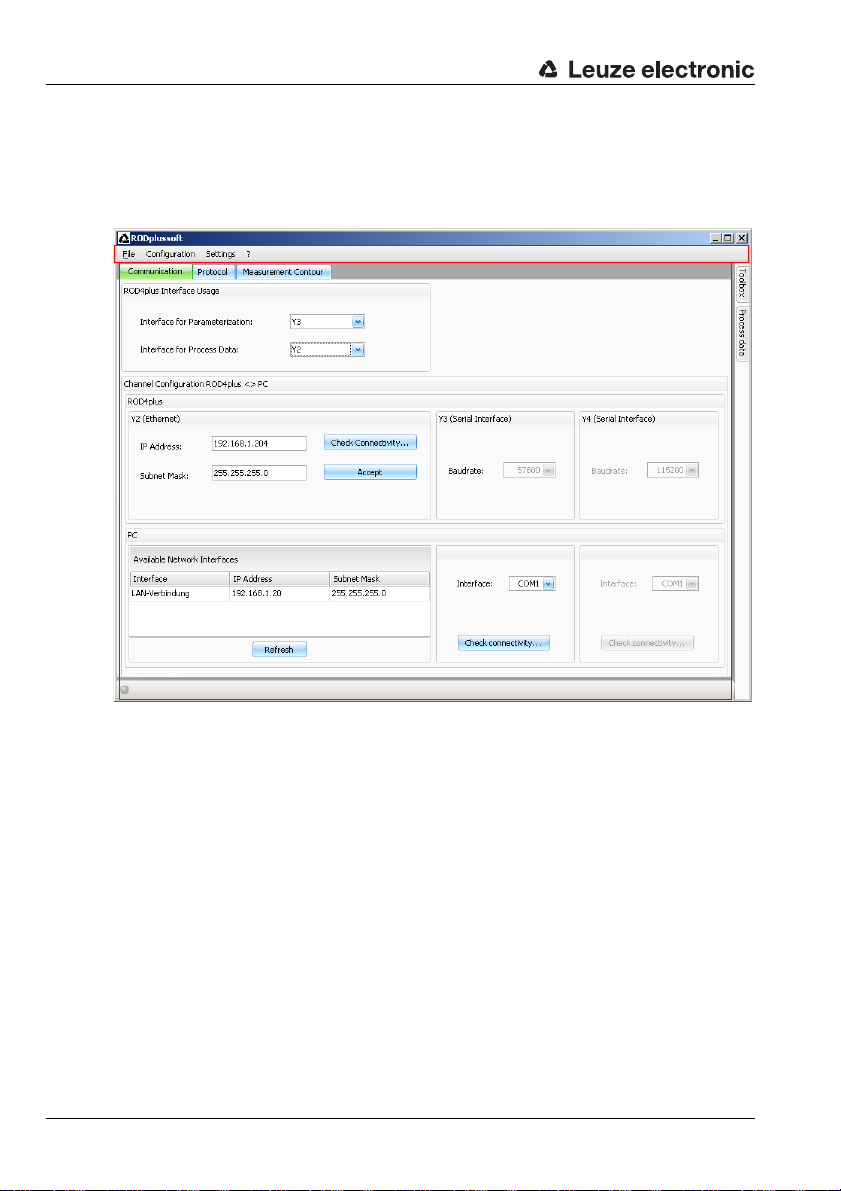
1
2
1 - Menu bar
2 - Configuration/measurement box
3.2 Starting the program
ª
To start RODplussoft, open the Windows
Start menu ->
The following screen appears, split into two areas:
All Programs
®
->
Leuze electronic
->
RODplussoft
.
6 RODplussoft - Software and protocol description Leuze electronic
Page 8

First steps - sample application
3.3 Adjusting the interface for parameterization
ª
In the
Communication
ration/measurement box, select interface
Interface for Parameteriza-
Y3 as
tion
. You previously connected this inter-
face to a free COM port on your PC.
ª
In the
PC -> Interface
munication
face) to which Y3 is connected.
RODPlussoft then automatically sets the
required interface parameters for the selected
COM port.
Click
ª
mine whether your PC can communicate
with the ROD4…plus.
tab, set the COM port (inter-
Check connectivity…
tab in the configu-
part of the
Com-
to deter-
3.4 Selecting the Interface for Process Data on the PC
The interface for process data is used both for displaying process data (measurement data)
and for transmitting online commands via the ASCII Remote protocol. On the ROD4…plus,
the Y2 (Ethernet) and Y4 (serial) interfaces are available for this purpose. First, you must
select which of these interfaces is connected to your PC and then make the settings for this
interface, see chapter 3.4.1 and chapter 3.4.2.
In the
ª
Interface for Process
area in the configuration/measure-
Data
ment box on the
select the interface of the ROD4…plus
that you have connected to the PC.
Communication
tab,
TNT 35/7-24V
3.4.1 Configuring the Ethernet interface of the ROD4…plus
If you have selected Y2 as the interface for process data, you still need to set the IP address
of the ROD4…plus. In order to be able to display the measurement data on the PC, the IP
address of your PC and the IP address of the ROD4…plus must lie in the same address
Leuze electronic RODplussoft - Software and protocol description 7
Page 9
First steps - sample application
range. The ROD4…plus has no built-in DHCP client, so that you need to set the address
manually.
Notice!
If you are using a desktop firewall, please ensure that RODplussoft can communicate with
the ROD4…plus via the Ethernet interface on port 9008. Furthermore, the firewall must allow
ICMP echo messages to pass through for the connection test (ping).
In this example, we assume that PC and ROD4…plus are in the same network segment
(subnet).
Find an unused IP address in the network
ª
in which the ROD4…plus is to be used, or
ask the responsible network administrator to allocate an address for the
ROD4…plus.
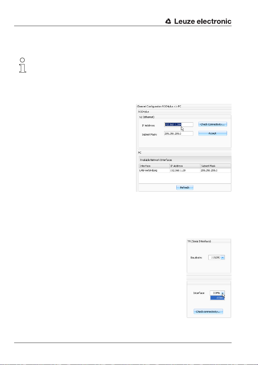
ª
In the
Y2 (Ethernet)
figuration/measurement box on the Communication
IP Address
the
ª
Enter the
your network configuration.
ª
Click
ª
If the connectivity test was successful,
you can accept the settings in the
ROD4…plus by clicking the
The configuration data are now transferred to the ROD4…plus and the measurement data
are displayed in the Measurement Contour area.
tab, enter this address in
Subnet Mask
Check connectivity…
area in the con-
field.
according to
.
Accept
button.
3.4.2 Configuring serial interface Y4 of the ROD4…plus
If you have selected Y4 as interface for process data, you now only
need to select the COM port on the PC to which you have connected
Y4.
In the
ª
Y4 (Serial Interface)
tab, select the COM port to which Y4 is connected.
RODPlussoft then automatically sets the required interface parameters for the selected COM port.
Click
ª
Check connectivity
can communicate with the ROD4…plus.
8 RODplussoft - Software and protocol description Leuze electronic
part of the Communication
… to ascertain whether your PC
Page 10
First steps - sample application
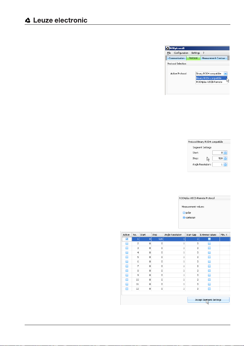
3.5 Configuring the measurement data protocol of the ROD4…plus
Two different protocols are available for the measurement data transfer:
• Binary ROD4 compatible (see chapter 5)
for the fast and efficient measurement data transfer, no remote control of the ROD4…plus is possible.
• ROD4plus ASCII Remote (see chapter 6)
for extended, flexible measurement data transfer
and remote control of the ROD4…plus.
In the
ª
Active Protocol
tab, select the desired protocol.
You can now make further settings depending on which protocol is selected.
3.5.1 Settings for the ROD4-compatible binary protocol
Under Protocol Binary ROD4 compatible, define the start
segment (see chapter 5.1.8), stop segment (see chapter 5.1.9) and
angular resolution (see chapter 5.1.7).
Set the values as shown in the screenshot:
ª
Start = 0, Stop = 528, Angle resolution = 1
You may change these values later.
3.5.2 Settings for the ASCII Remote protocol
Under Protocol ROD4plus ASCII Remote, specify whether
measurement data are to be transferred in polar or Cartesian
coordinates.
Set
ª
cartesian
.
area in the configuration/measurement box on the
.
Protocol
You must then define and activate
at least one measurement
segment to be able to start measurement operation of the
ROD4…plus.
Set the values for segment
ª
as shown in the screenshot,
1
set the tick in
click
tings
Leuze electronic RODplussoft - Software and protocol description 9
Active
Accept Segment Set-
.
no.
and then
TNT 35/7-24V
Page 11
First steps - sample application
Measurement
contour
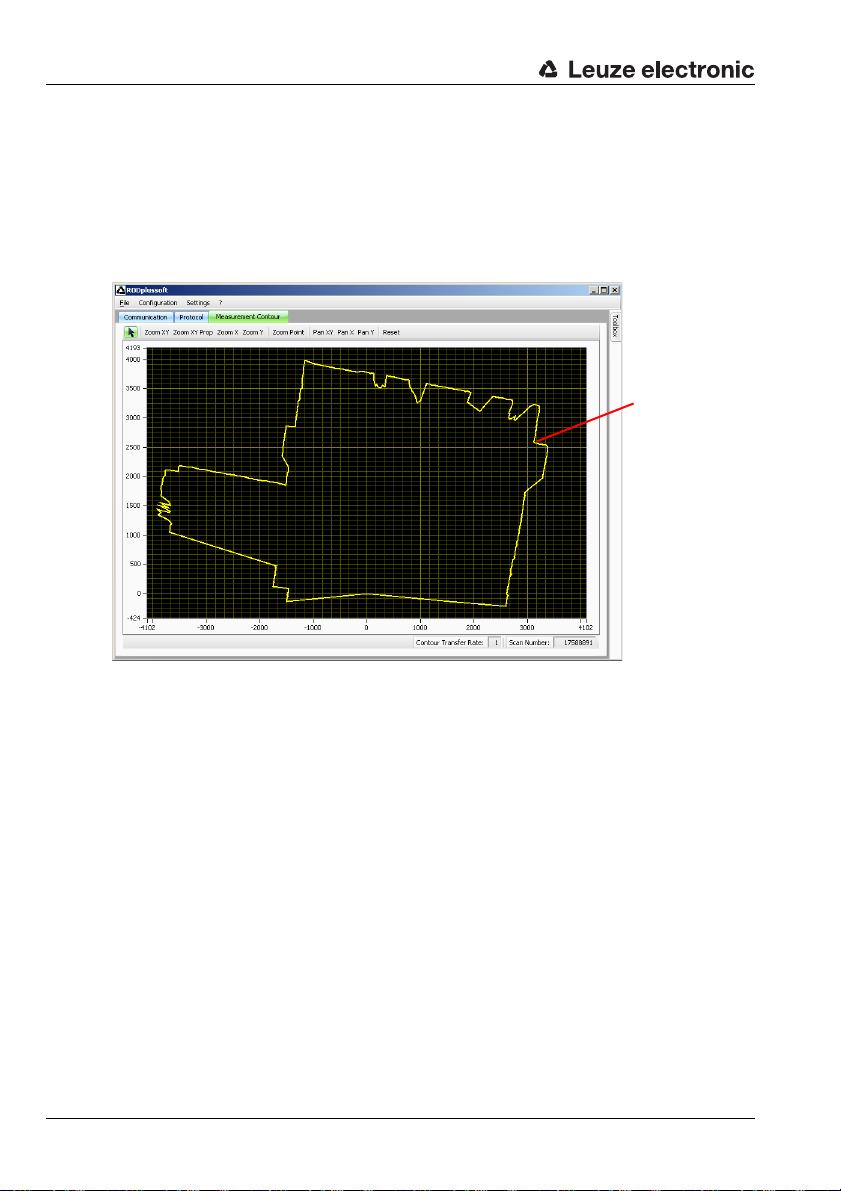
3.6 Displaying the measurement contour
After all interfaces are correctly connected, RODplussoft can receive measurement data
from the PC and display the data in the Measurement Contour window area.
Click the Measurement Contour tab.
ª
This starts the measurement and transfers the measurement data. RODplussoft graphically displays the measurement data as a measurement contour.
The ROD4…plus is located at coordinates 0/0. The measurement contour graphically
displays the measured distance within the measurement range of the ROD4…plus. This
distance can also be read directly on the coordinate axes in mm.
10 RODplussoft - Software and protocol description Leuze electronic
Page 12
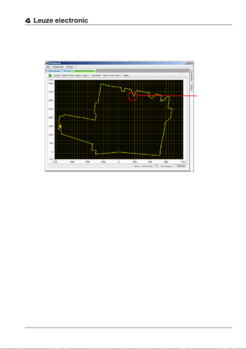
3.7 Configuring measurement segments
Object
Insert an object into the detection field of the ROD4…plus at a position that you want to use
for measurements later.
You can now restrict the measurement range of the ROD4…plus to the area around this
object in order to transfer only those measurement data which are actually of interest. The
procedure depends on the active protocol selected and is described in the next two
subchapters.
First steps - sample application
Leuze electronic RODplussoft - Software and protocol description 11
TNT 35/7-24V
Page 13
First steps - sample application
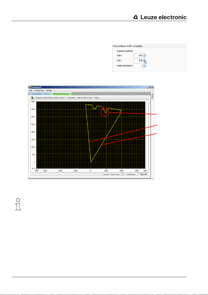
Object
Start = 250
Stop = 350
3.7.1 Configuring measurement segments for the ROD4-compatible binary protocol
ª
Switch to the
ment with the measurement segment settings under
compatible
The settings shown in our example result in
the following measurement contour:
Protocol
Protocol Binary ROD4
tab and experi-
.
You can fine-tune and adapt these settings further depending on the angular range and
resolution you wish to measure with.
Notice!
The settings made under the ROD4-compatible binary protocol persist even after the
ROD4…plus has been switched off. This lets you take the thus configured ROD4…plus and
commission it directly on the process control.
12 RODplussoft - Software and protocol description Leuze electronic
Page 14

First steps - sample application
Object 1
Object 2
Measurement segment
1
(yellow)
Measurement segment
2
(green)
Contour transfer rateMeasurement segment
3
(orange)
3.7.2 Configuring measurement segments for the ASCII Remote protocol
Here we show as an example the configuration of 3 measurement segments and two objects
entering the detection area of the ROD4…plus.
On the
ª
Protocol
Start, Stop, Angle Resolution
Scan Gap
and
measurement segments and transfer
the so-defined measurement segments to the ROD4…plus by clicking the
The settings shown in our example result in the following measurement contour:
tab, change the
values for one or more
Accept Segment Settings
button.
Leuze electronic RODplussoft - Software and protocol description 13
In the areas marked yellow, green, and orange, measurement values are now transferred.
Note that for the ASCII Remote protocol with maximum data transmission rate at the interface, less data may be transferred than are delivered by the ROD4…plus. Looking at the
Contour Transfer Rate tells us whether this is the case here, too. If the value = 1, each
measured contour is also transferred.
With a contour transfer rate > 1, not all measured contours are transferred. In our example,
only every second measurement contour is transferred. To obtain consistent data, make
certain that the contour transfer rate = 1.
TNT 35/7-24V
Page 15

First steps - sample application
Object contours are captured with less
accuracy
Every scan is transferred
There are two ways to achieve this:
• Increasing the value for Angle Resolution.
This reduces the angular resolution, and with it the amount of data to be transferred.
• Increasing the value for Scan Gap.
This increases the time interval between the transfer of two scans. The angular resolution remains the same, but movements are captured less precisely.
Increasing the value for Gap to 7 results in the following figure:
In particular, the contour of the small object in the green measurement segment 2 is no
longer resolved accurately. Instead, all scans are now transferred completely.
14 RODplussoft - Software and protocol description Leuze electronic
Page 16

First steps - sample application
Object contours are captured more
precisely
Every 4th scan is transferred
This is perhaps not sufficiently accurate. We start another attempt with angle Angle
resolution = 2 and Scan Gap = 3.
This lets you obtain the optimum values for the application through trial and error.
Note down the values of
ª
of the measurement segments configured here, and program your process control such
that the these calculated values are used to configure the ROD4…plus via the online
command ’CS’ (see chapter 6.1.2).
Start, Stop, Angle Resolution,
and
Scan Gap
for each
Notice!
The segment settings carried out via the ASCII Remote protocol are volatile. In combination
with the ASCII Remote protocol, the RODplussoft is predominantly intended for the graphical display of the measurement area and for finding the values for the measurement segments.
Leuze electronic RODplussoft - Software and protocol description 15
TNT 35/7-24V
Page 17

Menu description
1
3
4
1 - Menu bar
2 - Configuration/measurement box
3 - Toolbox docking window
4 - Process data docking window
2
4 Menu description
The RODplussoft program window can be divided into 4 areas which are described here in
the order specified.
16 RODplussoft - Software and protocol description Leuze electronic
Page 18

4.1 Menu bar
The menu bar is used for the basic operation of the software. It consists of 4 menu items.
4.1.1 File
Configurations of the ROD4…plus may be edited either with or without a
ROD4…plus connected, and may be saved as files in the *.r4p format. The
file menu is used to administer these files:
• New opens a new blank configuration file.
• Open opens a configuration file which has earlier been stored on the
hard disk.
• Save as saves the current configuration on the hard disk under a different name.
• Record saves the measurement data of the ROD4…plus in file(s) on the hard disk. A
detailed description can be found in "Process data" on page 27.
• Exit closes RODplussoft.
4.1.2 Configuration
The data exchange between RODplussoft and the ROD4…plustakes place in the Configuration menu.
• Start RODsoft starts the RODsoft program for configuring the detection functions of the ROD4…plus.
• Load from ROD4plus loads the configuration of the connected ROD4…plus.
• Transmit to ROD4plus saves the current configuration in the ROD4…plus.
Note here that only settings for the "Binary ROD4 compatible" protocol are retained
after the ROD4…plus is switched off.
Menu description
4.1.3 Settings
Under Settings, you can set the language of the
RODplussoft user interface.
• Language selects the dialog language (German/English).
Notice!
If RODsoft is also installed on the same computer, the language set here is also set in RODsoft if the
Leuze electronic RODplussoft - Software and protocol description 17
Configuration -> Start RODsoft
menu command is executed.
TNT 35/7-24V
Page 19

Menu description
4.1.4 Question mark ’?’
The first three menu items in the question mark ’?’ menu each invoke PDF documents. This
requires the Adobe Acrobat Reader
• Datasheet
• Technical Description
• Software and Protocol Descrip-
tion
About RODplussoft... displays informa-
tion on the software version.
®
to be installed on your PC.
18 RODplussoft - Software and protocol description Leuze electronic
Page 20

4.2 Configuration/measurement box
The configuration/measurement box contains three tabs: Communication, Protocol
and Measurement Contour.
4.2.1 Communication
The Communication tab is used to configure the measurement data transfer of the
ROD4…plus.
Menu description
ROD4plus Interface Usage
In the ROD4plus Interface Usage window area, specify the interfaces of the
ROD4…plus that you use.
The Interface for Parameterization is
used for communication between RODplussoft
(and RODsoft) and ROD4…plus. Available for
selection are Y2, Y3 and Y4.
Leuze electronic RODplussoft - Software and protocol description 19
TNT 35/7-24V
Page 21

Menu description
Notice!
If you would like to use RODsoft, you must first have selected Y3 as the interface here and
have made the connection to the PC. If this has not yet been performed, the following warning appears:
The Interface for Process Data is used to transfer the measurement data between
RODplussoft and ROD4…plus. Available for selection are Y2 and Y4.
Notice!
You have the option of selecting the same interface for configuration and process data (
or Y4). Thus, you can minimise wiring work and connect just one cable from the ROD4…plus
to the PC. If you would like to use only Y2 (without preconfiguring the Ethernet interface via
Y3), please note that you must then manually set your PC to an address in address range
192.168.60.xxx
ROD4…plus
with the
Channel configuration ROD4plus <> PC
Depending on the selected interfaces, set additional parameters here for ROD4plus and PC.
For the ROD4…plus, you can set the
IP Address and the Subnet Mask for Y2
(Ethernet) under which the ROD4…plus is
to be addressed during operation.
The default address is 192.168.60.3 with
subnet mask 255.255.255.0.
The Check Connectivity button sends a
ping command to the set IP Address, checks whether the ROD4…plus answers this ping
command, establishes a connection, transfers data, and then tears down the connection.
Use the Accept button to save changed values for IP Address and Subnet Mask in
ROD4…plus.
Under Y3 (Serial Interface), there are no
options for making settings; only the permanently set baud rate is displayed.
Under Y4 (Serial Interface) you can see
the Baudrate for the RS 232/422 transfer.
(in the factory configuration of the
.
ROD4…plus
Y2
) in order to communicate
For the PC, an overview of the IP configuration
for your PC is displayed in the Available
Network Interfaces window area.
20 RODplussoft - Software and protocol description Leuze electronic
Page 22

If interfaces Y3 and/or Y4 were selected under ROD4plus Inter-
face Usage, then use this option to set the COM port on the PC to
which the interfaces are connected. Immediately after making this
setting, you can Check connectivity.
4.2.2 Protocol
Depending on which protocol is enabled, the RODplussoft offers different options for
settings.
For Protocol Binary ROD4 compatible,
you can define a measurement segment
whose data are transferred. In doing so, you
specify the Start angle (0 … 528) from which
the measurement data transfer is to begin, the
Stop angle (0 … 528) to which the measurement data transfer is to take place, and the
Angle Resolution between two transferred
angular segment (1 … 8). The measurement
data transfer always occurs here in polar coordinates.
With ASCII Remote, you can only select
whether the measurement data are to be transferred in polar or cartesian form.
Menu description
Configuring measurement segments
In the lower part of the protocol window, you
can define up to 12 measurement segments.
Click Accept Segment Settings to overwrite the segment definitions configured in the
RAM of the ROD4…plus with the settings made here. Measurement segments previously
defined in the ROD4…plus are deleted in this process unless the Active tick is set for the
respective segment number.
Leuze electronic RODplussoft - Software and protocol description 21
TNT 35/7-24V
Page 23

Menu description
Notice!
To display a measurement contour, you must have defined and activated at least 1 measurement segment and transferred these settings to the ROD4…plus by clicking
Segment Settings
Measurement data transfer of the ROD4…plus occurs only for the activated segments.
This lets you reduce the transferred data volume to the data required for your application.
A tick in front of Active activates the defined segment (after data transfer with the Accept
Segment Settings button).
The number in Start specifies at which angular segment number of a scan the measurement data output is to begin, and the number in Stop specifies where the measurement data
output finishes.
In Angle resolution, you specify whether all measurement values of the scan (Angle
resolution = 1), only every second value (Angle resolution = 2), etc., are trans-
ferred between Start and Stop. This lets you reduce the data quantity transferred if the
maximum angular resolution of the ROD4…plus is higher than the resolution required for the
application. The Angle Resolution may be set in the range from 1 … 8.
In Scan Gap you specify whether all scans (Scan Gap = 0) only every second scan
(Scan Gap = 1), etc., are transferred. This lets you again considerably reduce the data
quantity transferred, if the response time required for the application exceeds the duration
of the scan (40ms). Scan Gap may be set in the range from 0 … 11.
Notice!
The two functions described in the following: Extreme Values and Measurement Value Fil-
tering are only available if Cartesian measurement data transfer is selected.
Accept
.
22 RODplussoft - Software and protocol description Leuze electronic
Page 24

Menu description
Outputting extreme values
A tick in the Extreme Values field results in only the extreme values being transferred for
the respective measurement segment, i.e. the minimum value and maximum values for X,
Y and radius. The function is illustrated in the two following screenshots. In the image on the
left, the entire measurement contour is transferred; in the image on the right, on the other
hand, only the extreme values are transferred, which the RODplussoft then consequently
displays as individual points.
For better understanding, we will consider some sample process data. Measurement
segment No. 1 is configured with Start = 50, Stop = 80, Angle Resolution = 4,
Scan Gap = 0; Extreme Values are not activated:
As a result, 9 measurement values are output in X/Y coordinates for each scan.
If extreme value output is now activated, the process data change:
Now, only the extreme values are output in X/Y coordinates in the following order:
- Coordinate with minimum X-value
- Coordinate with maximum X-value
- Coordinate with minimum Y-value
- Coordinate with maximum Y-value
- Coordinate with minimum radius
- Coordinate with maximum radius
Leuze electronic RODplussoft - Software and protocol description 23
TNT 35/7-24V
Page 25

Menu description
Measurement value filtering
You can further reduce the measurement values transferred within a segment by entering
minimum and maximum values for X, Y and radius in the provided fields. Measurement
value transfer then only occurs within the defined ranges. This can be useful on a conveying
belt, for example, for outputting only measurement values for objects which lie on the
conveying belt.
The following example illustrates the effect
of the filter:
In the first segment, a filter is set that only
outputs measurement values with Xvalues greater than -1700mm (Min. X).
In the second segment, only measurement values with Y-values less than 3500mm
(Max. Y) are output. In the third segment, only measurement values with radii less than
4200mm (Max. Radius) are output.
At the left we see the measurement contour without filter; at the right with activated filter:
For better understanding, we will again consider some sample process data. Only measurement segment No. 1 is configured with Start = 50, Stop = 80, Angle
Resolution = 4, Scan Gap = 0; Extreme Values are not activated:
As a result, 9 measurement values are output in X/Y coordinates for each scan.
If a measurement value filter is set to Max. X 0 -3500, only measurement values whose
X-value is less than -3500 are output:
24 RODplussoft - Software and protocol description Leuze electronic
Page 26

4.2.3 Measurement contour
The Measurement Contour
tab is used to display the data
measured by the ROD4…plus.
For this purpose, the Inter-
face for Process Data
must be connected to the PC
and the measurement function
activated.
This is automatically the case
if the active protocol is Binary
ROD4 compatible.
For ROD4plus ASCII-
Remote, you must first define
measurement segments and
start the measurement.
Toolbar
RODplussoft is equipped standard with a toolbar for viewing the measurement contour. This
bar appears automatically when the Measurement Contour tab is selected in the configuration/measurement box.
• Zoom XY zooms to the area in measurement contour defined by clicking and dragging. Different zoom factors in x- and y-direction are possible.
• Zoom XY Prop zooms in the same way as before, but with the same zoom factor in
x- and in y-direction.
• Zoom X magnifies the display of the x-axis only, while the scale of the y-axis remains
the same.
• Zoom Y magnifies the display of the y-axis only, while the scale of the x-axis remains
the same.
• Zoom Point zooms in on the point which is clicked and centres it in the middle of the
measurement window.
•With Pan XY, the displayed section of the measurement contour can be moved in x-
and y-direction while pressing the mouse button.
• Pan X moves in x-direction only.
• Pan Y moves in y-direction only.
• Reset adjusts the view so that the measured contour optimally fits into the xy-plane.
Menu description
TNT 35/7-24V
Attention!
The scale in x- and y-direction is not fixed but varies according to the shape and size of the
RODplussoft window. To obtain the most realistic possible representation of the measurement contour, you should first adjust proportions of the RODplussoft window to those of the
area monitored by the ROD4…plus.
Leuze electronic RODplussoft - Software and protocol description 25
Page 27

Menu description
4.3 Toolbox and Process Data docking windows
In the Toolbox docking window, you can enter online commands for controlling the
ROD4…plus with the ASCII Remote protocol. For this purpose, the ROD4…plus must first
be connected to the PC via the previously defined Interface for Process Data and the
ASCII Remote protocol defined as the active protocol.
The Process data docking window is used for the numerical display of the measurement
data.
4.3.1 Toolbox
The Toolbox is divided into 3 areas. These areas can be
shown or hidden by clicking on the arrow on the top right of
the title bar.
Terminal
In the upper input field of the Terminal area, you can
enter arbitrary online commands for the ROD4…plus and
transfer them by clicking on the tick. The response of the
ROD4…plus will then appear in the output field located
below (for online commands see chapter 6.1).
Service
Under Service, you can query the firmware version of the
ROD4…plus (Version) and reset the ROD4…plus
(Reset).
Operation mode
Under Operation mode, you can activate (M+) or deactivate
(M-) the continuous measurement, or carry out an individual measurement (M).
Notice!
The measurement data are transferred only if at least one
measurement segment has been configured and the meas-
M
urement process has subsequently been started with
M+
.
26 RODplussoft - Software and protocol description Leuze electronic
or
Page 28

4.3.2 Process data
The Process data window displays the ASCII measurement data transfer of the
ROD4…plus.
Two measurement segments are configured in the examples below. Segment No. 1 with
Start = 0 and Stop = 0, Segment No. 2 with Start = 1 and Stop = 2. Thus, for
segment 1, one measurement value is transferred; for segment 2, two measurement values
are transferred.
In the upper screenshot, measurement data transfer is cartesian; in the lower, it is polar.
The respective first lines read as follows:
Cartesian:
- Scan number 0000014251
- Segment 1 with measurement value
X = -1486mm, Y = -131 mm
- Segment 2 with measurement values X1 = -1485mm, Y1 = -121mm,
X2 = -1479mm, Y2 = -111 mm
Polar:
- Scan number 0000012903
- Segment 1 with measurement value
radius = 1500mm
- Segment 2 with measurement values radius 1 = 1494mm,
radius 2 = 1490mm
Menu description
Recording process data
In addition to the pure screen output, RODplussoft also offers the option of writing measurement data to one or more files.
Click Record in the File menu to
open the following window:
Here, you can use Choose File to
define a CSV file name in which the
measurement data are to be stored.
Use the Recording Volume to
define the maximum quantity of data
(in kByte) that is to be recorded.
Use Maximum File Size to define
the maximum size of a recording file; for larger volumes of data, multiple files are then
created with the file name defined above and appended with ordinal numbers.
The measurement values are always recorded in X/Y coordinates independent of measurement protocol.
Leuze electronic RODplussoft - Software and protocol description 27
TNT 35/7-24V
Page 29

ROD4-compatible binary protocol
5 ROD4-compatible binary protocol
The structure of the ROD4-compatible binary protocol cannot be specified by the user.
If the ROD4-compatible binary protocol is set as the active protocol, the ROD4…plus continuously sends data with the protocol described here after application of the supply voltage
and the subsequent self test (in operation without RODplussoft). The protocol data are
always bordered by a start frame and an end frame.
The ROD4…plus cannot receive data from the PC via this protocol, which means it is a kind
of 'one-way' protocol.
Notice for Ethernet connections!
If you are using a desktop firewall, please ensure that RODplussoft can communicate with
the ROD4…plus via the Ethernet interface on port 9008. Furthermore, the firewall must allow
ICMP echo messages to pass through for the connection test (ping).
5.1 Protocol structure
The protocol structure is described chronologically from top to bottom. The possible values
of individual bytes and their meaning are described below.
No. of bytes
Tim
Designation
e
2
Ð
1
Ð
1
Ð
1
Ð
1
Ð
8
Ð
1
Ð
2 (3)
Ð
2 (3)
Ð
2x no. of
Ð
meas. val-
2)
ues
1
Ð
3
Ð
1) 3 bytes, if the value = 0, see note on page 29
2) + number of 0xFF inserted
Start
Operation
Option 1
Option 2
Option 3
Scan number
Angular resolution
1)
Start angle
1)
Stop angle
Distance
measurement value
Check byte
End
Description
Start of the data transfer from the ROD4…plus
Normal operation / error / warning
Is always transferred, indicates the operating state, and
whether Options 2 and 3 are transferred
State of the detection fields near and far
Active field pair
Is incremented by 1 following each scan of the ROD4 to
permit each scan to be uniquely identified
Angular separation between two subsequently transferred measurement values
Angle at which the measurement value output starts for
each scan
Angle of the most recently transferred measurement
segment for each scan
Output of the distance measurement values of the
entire scan in sequence
XOR of all characters transferred
End of the data transfer from the ROD4…plus
28 RODplussoft - Software and protocol description Leuze electronic
Page 30

Attention!
If two zeros follow each other in the data stream, a byte with the value 255 is inserted. A
distance measurement value of 0, for example, is represented as 0x00 0x00 0xFF.
5.1.1 Start
The start character consists of two bytes that always have the value 0x00,0x00.
MSB start byte 1 LSB MSB start byte 2 LSB
0 0 0 0 0 0 0 0 0 0 0 0 0 0 0 0
5.1.2 Operation
The operation character consists of one byte and identifies the message type.
MSB operation byte LSB Meaning of the bits
0 0 1 0 0 0 1 1 0x23 = measurement values are transferred
5.1.3 Option 1
Option byte 1 is always transferred and indicates whether further option bytes follow. Information on the operating state is also transferred again, so that the correct working of the
data transmission can be checked via redundant data.
MSB option byte 1 LSB Meaning of the bits
ROD4-compatible binary protocol
0 1 Option 1 only
1 0 Option 1 + Option 2
1 1 Option 1 + Option 2 + Option 3
0 0 1 Initialisation
0 1 0 Measurement operation (normal operation)
1 0 0 Error / fault
TNT 35/7-24V
Leuze electronic RODplussoft - Software and protocol description 29
Page 31

ROD4-compatible binary protocol
5.1.4 Option 2
Option byte 2 specifies whether objects have been detected in the near and far detection
fields. Information on the operating state is also transferred again, so that the correct
working of the data transmission can be checked via redundant data.
MSB option byte 2 LSB Meaning of the bits
0/1 1 = warning
0/1 1 = fault
0/1 1 = restart-disable
0/1 1 = detection field near 2 occupied
0/1 1 = detection field far 2 occupied
0/1 1 = option byte 3 is transferred
5.1.5 Option 3
The option byte 3 It specifies which field pairs are transferred as detection field 1 and detection field 2 in option byte 2.
MSB option byte 3 LSB Meaning of the bits
1 E1.2 E1.1 E1.0
1 E2.2 E2.1 E2.0
1 0/1
0/1 1 = detection field near 1 occupied
0/1 1 = detection field far 1 occupied
001: detection field 1 = field pair 1 to
100: detection field 1 = field pair 4
001: detection field 2 = field pair 1 to
100: detection field 2 = field pair 4
specifies the state of outputs Fn1/Fn2.
0 = outputs Fn1/Fn2 switched off
5.1.6 Scan number
The scan number can be used to determine the time between two transferred scans. For
each individual scan, the ROD4…plus increments the scan number by 1. The ROD4…plus
captures 25 individual scans per second.
The scan number itself consists of 32 bits. To prevent a small value in the transfer of 4 bytes
from creating a double null (i.e., start sequence), fill bytes with a value of 0xFE are inserted
between the individual bytes of the scan number.
MSB scan number (8 bytes) LSB
byte 3 fill byte byte 2 fill byte byte 1 fill byte byte 0 fill byte
xxxx xxxx 1111 1110 xxxx xxxx 1111 1110 xxxx xxxx 1111 1110 xxxx xxxx 1111 1110
30 RODplussoft - Software and protocol description Leuze electronic
Page 32

5.1.7 Angular resolution
The angular resolution specifies the angular separation between two successively transferred measurement values as a multiple of 0.36 °.
Factory setting: 1
MSB angular resolution LSB Example
x x x x x x x x 0000 0101: angular resolution = 1.8°
5.1.8 Start angle
This value specifies the angular segment of the current scan at which the measurement
value output begins. Possible values: 1 (0x00,0x01) = start angle -5.04° to 529 (0x02,0x11)
= start angle 185.04°.
Factory setting: 1
MSB start angle byte 1 LSB MSB start angle byte 2 LSB Example
x x x x x x x x x x x x x x x x
Notice!
The value range here extends from 1 to 529, unlike the 0 to 528 for the ROD4plus ASCIIRemote protocol. This prevents the output of two successive zeros for start/stop angle = 0.
5.1.9 Stop angle
This value specifies the angular segment of the current scan at which the measurement
value output ends. Possible values: 1 (0x00,0x01) = stop angle -5.04° to 529 (0x02,0x11) =
stop angle 185.04°.
Factory setting: 529
MSB stop angle byte 1 LSB MSB stop angle byte 2 LSB Example
x x x x x x x x x x x x x x x x
ROD4-compatible binary protocol
0x00 0x0A: start angle = 10 =
-1.8°
0x00 0x14: stop angle = 20 =
1.8°
TNT 35/7-24V
Notice!
The value range here extends from 1 to 529, unlike the 0 to 528 for the ROD4plus ASCIIRemote protocol. This prevents the output of two successive zeros for start/stop angle = 0.
Leuze electronic RODplussoft - Software and protocol description 31
Page 33

ROD4-compatible binary protocol
5.1.10 Distance measurement value
All distance measurement values that were measured between start and stop angle using
the previously defined angular resolution are transferred as successive 2 byte values.
MSB distance byte 1 LSB MSB distance byte 2 LSB Meaning of the bits
xxxxxxxxxxxxxxx
The following table shows by means of example the chronological order of distance measurement values transmitted for start angle = 10, angular resolution = 2, stop angle = 18:
Bytes
Tim
e
Ð
Ð
Ð
Ð
Ð
0x10, 0x00
0x10, 0x01
0x10, 0x03
0x10, 0x02
0x10, 0x04
Designation
Distance 1
Distance 2
Distance 3
Distance 4
Distance 5
1 = object in detection field
0/1
near detected
15 bit distance measurement value with 2mm resolution
Meaning
4096mm at angle -1.8 ° (angular segment no. 10),
no object in detection field near
4096mm at angle -1.08 ° (angular segment no. 12),
object in detection field near
4098mm at angle -0.36 ° (angular segment no. 14),
object in detection field near
4098mm at angle 0.36 ° (angular segment no. 16),
no object in detection field near
4100mm at angle 1.08 ° (angular segment no. 18),
no object in detection field near
5.1.11 Check byte
The check byte has a value range of 0x01 to 0xFF.
It is the result of an XOR of all bytes transferred, including operation and option bytes, i.e.,
from after the start byte up to the last byte before the check byte.
To avoid collision with the end mark, the check byte must never have the value 0x00. If a
0x00 is calculated as the result of the XOR, then a 0xFF is transferred as check character
and used for the evaluation.
MSB check byte LSB Meaning of the bits
x x x x x x x x XOR of all bytes from the start to the check byte
5.1.12 End
The end mark consists of three bytes that always have the value 0x00,0x00,0x00.
MSB end byte 1 LSB MSB end byte 2 LSB MSB end byte 2 LSB
0 0 0 0 0 0 0 0 0 0 0 0 0 0 0 0 0 0 0 0 0 0 0 0
32 RODplussoft - Software and protocol description Leuze electronic
Page 34

6 ASCII-Remote protocol
The ASCII-Remote protocol is used to configure the ROD4…plus from a terminal using
commands known as 'online commands' and to carry out simple measurement tasks, the
results of which are also directly displayed in the terminal window.
Prerequisites for using the ASCII-Remote protocol:
• The ROD4plus… has been configured with RODsoft or RODplussoft such that
• Y2 or Y4 is defined as the active interface, and
• the ASCII-Remote protocol has been activated.
Notice!
Settings applied via the ASCII-Remote protocol are only temporarily stored in the
ROD4…plus and are lost when the ROD4…plus is switched off.
Notice for Ethernet connections!
If you are using a desktop firewall, please ensure that RODplussoft can communicate with
the ROD4…plus via the Ethernet interface on port 9008. Furthermore, the firewall must allow
ICMP echo messages to pass through for the connection test (ping).
6.1 Online commands
With the commands, you can
• configure up to 12 segments within which measurement values are transferred
• configure measurement value filtering
• activate/deactivate extreme value transfer
• delete configured segments
• activate/deactivate measurements
• query device information
• carry out a software reset in order to reinitialise the device
ASCII-Remote protocol
Syntax
"Online" commands consist of one or two ASCII characters followed by command parameters. An ’STX’ (0x02) must be transferred prior to each command and an ’ETX’ (0x03) must
be transferred afterward.
No separation characters may be entered between the command and the command parameter(s). Capital letters must be used.
Example:
Command ’M’: Measurement function
Parameter ’+’: activates the continuous measurement
Transmitted is: ’M+’
Notation
Commands, command parameters and returned data are enclosed between single quotation marks ’ ’ in the text of this manual. The ROD4…plus responds to an 'Online' command
with an acknowledgement or returns measurement data.
Leuze electronic RODplussoft - Software and protocol description 33
TNT 35/7-24V
Page 35

ASCII-Remote protocol
6.1.1 General 'Online' Commands
Software version number
Corresponds to the "Version" command in the RODplussoft toolbox.
Command ’V’
Description Requests device version information
Parameter -
Acknowledgement
Notice!
Use this command to check whether the ROD4…plus is connected and configured correctly.
If you do not receive an acknowledgement, please check interface connections and protocol.
Software reset
Corresponds to the "Reset" command in the RODplussoft toolbox.
Command ’H’
Description
Parameter -
Acknowledgement -
’V 01.01.01’
The software version number of the ROD4…plus is shown.
Carries out a software reset. The device is restarted and reinitialised,
leaving it in the same state as when the supply voltage is switched on.
34 RODplussoft - Software and protocol description Leuze electronic
Page 36

ASCII-Remote protocol
6.1.2 Online commands for configuration of the measurement function
The commands described here correspond in function to the adjustment options in the
Protocol window area in RODplussoft (see chapter 4.2.2).
Measurement segment configuration
Command ’CS’
Description The command configures one of 12 possible measurement segments.
’_x_yyy_zzz_l_s’ Replace the '_' characters by space characters
Measurement segment number
’x’
’yyy’
Parameter
Acknowledgement
Example ’CS 1 264 300 2 1’
’zzz’ Stop angular segment: 0 … 528
’l’
’s’
-
-
Notice!
Measurement segments should be defined so that the start angular segment of the measurement segment is always larger than the stop angular segment of the previous measurement segment, i.e. each individual angular segment should only be contained once in one
of the measurement segments.
If an angular segment is contained in multiple measurement segments, the corresponding
measurement value is transferred only in the first measurement segment which contains
the angular segment.
Example: Defined in measurement segment 1 are yyy = 100 and zzz = 120; defined in
measurement segment 2 are yyy = 110 and zzz = 130. Measurement data transfer occurs
for angular segment 100 to 120 in measurement segment 1 and for 121 to 130 in measurement segment 2.
Attention: if the number of an already defined
segment is specified here, the data are simply
overwritten without confirmation
Start angular segment: 0 … 528
start angular segment
Angular resolution, possible values: 1 … 8:
1 = each angular segment is transferred
2 = every second angular segment is transferred
Scan gap: distance between two scans transmitted, possible values: 0 … 11:
0 = each scan is transferred
1 = every second scan is transferred, etc.
Command accepted: start of measurement data
output for the selected measurement segment
Command not accepted: no measurement data
output for the selected measurement segment
Configurationof area 1, start at angular segment
264, end at angular segment 300, angular resolution = 2, i.e., a measurement value is transferred
every 0.72°, every second scan is transferred
≤ stop angular segment
TNT 35/7-24V
Leuze electronic RODplussoft - Software and protocol description 35
Page 37

ASCII-Remote protocol
Measurement area deletion
Command ’DS’
Description The command deletes one of 12 possible measurement segments.
Parameter ’_x’ Replace the '_' character by a space character
Acknowledgement
Example ’DS 1’ Deletes measurement segment 1
Notice!
At least 200ms must pass after sending 'CS' before a ’DS’ command is accepted.
Configuration of measurement value filtering
Command ’PS’
Description
Parameter
Acknowledgement
Example ’PS 1 SET MIN R 3000’
-
-
The command configures measurement value filtering for a previously
defined measurement segment.
’_x_aaa_bbb_c_d’ Replace the '_' characters by space characters
’x’
’aaa’
’bbb’
’c’
’d’ d = val ue
-
-
Command accepted: stop of measurement data
output for the selected measurement segment
Command not accepted: measurement data output
for the selected measurement segment continues
Measurement segment number
Attention: The measurement segment must
first be configured with ’CS’, otherwise nothing
happens here.
aaa = SET (activate) or
aaa = CLR (delete) measurement data filtering
for segment no. x
bbb = MIN (minimum value) or
bbb = MAX (maximum value)
c = X (X-values) or
c = Y (Y-values) or
c = R (radius values)
Command accepted: start of measurement
data filtering for the selected measurement
segment
Command not accepted: no measurement
data filtering for the selected measurement
segment
In segment 1, only the measurement values
with a radius greater than 3000mm are transferred.
36 RODplussoft - Software and protocol description Leuze electronic
Page 38

ASCII-Remote protocol
Configuration of extreme value output
Command ’FS’
Description
Parameter
Acknowledgement
Example ’FS 1 SET EXT’ Only extreme values are output in segment 1.
6.1.3 Online commands for measurement function control
Starting/stopping the measurement
Corresponds to the "Activate Measurement", "Deactivate Measurement" and "Individual
Measurement" commands in the RODplussoft toolbox.
The command configures extreme value output for a previously defined
measurement segment.
’_x_aaa_EXT’ Replace the '_' characters by space characters
Measurement segment number
’x’
’aaa’
-
-
Attention: The measurement segment must
first be configured with ’CS’, otherwise nothing
happens here.
aaa = SET (activate) or
aaa = CLR (delete) extreme value output for
segment no. x
Command accepted: start of extreme value
output for the selected measurement segment
Command not accepted: no extreme value
output for the selected measurement segment
Command ’M’
Description Controls the measurement function according to parameter.
’ ’
Parameter
Acknowledgement Measurement data output, see chapter 6.2
Example ’M+’
Leuze electronic RODplussoft - Software and protocol description 37
’+’ Activates the continuous measurement.
’-’ Deactivates the continuous measurement.
Without parameter: Individual measurement, transfers the next scan
Continuous measurement activated, the measurement values are output via the active process interface
TNT 35/7-24V
Page 39

ASCII-Remote protocol
6.2 Measurement data protocol
The ROD4…plus can continuously output measurement data. For this purpose, the measurement data of an individual scan are combined.
A measurement data transfer might look like the following, for example:
STX0001048577#001;00889;00890;...#002;00799;... ...;00800#ETX
The individual elements here are:
ASCII value
Time
STX=0x02
Ð
0000178923
Ð
#001;
Ð
008895;
Ð
008897;
008893;
…
+06615;-03475;
Ð
+06617;-03473;
+06611;-03472;
…
#ETX = 0x03
Ð
Designation
Preamble
Scan number
Segment number
then
Measurement
data, polar
coordinates
or
Measurement
data,
cartesian
coordinates
Suffix
Meaning
Indicates the beginning of a new individual
scan
Incremented by one for each individual scan,
labels each individual scan uniquely
Number of the measurement segment whose
measurement data are about to be transferred
Measurement values in mm for each angular
segment within the measurement segment
Cartesian measurement values in mm for each
angular segment within the measurement segment. Negative X values are located left of the
middle of the sensor, negative Y values behind
the front of the sensor.
Indicates the end of the individual scan just
transferred.
38 RODplussoft - Software and protocol description Leuze electronic
Page 40

7 Appendix
0.36°
Working range
Angular segment
528
Angular segment 0
7.1 Terms and abbreviations ROD4…plus software
The terms used in this description are most easily explained using the drawing below. The
ROD4…plus scans the area in front of it clockwise from left to right and calculates the
distance measurement values in steps of 0.36°.
Angular resolution
Distance between to measurement segments (angular segments) transferred, specified in number of angular segments.
Example:
• Angular resolution = 1: each measurement value of a measurement segment is
transferred
• Angular resolution = 2: every second measurement value of a measurement segment is transferred…
Angular segment
Uniquely identifies one of 529 measurement values of an individual scan.
Individual scan
Detection of 529 measurement values. The ROD4…plus requires 40ms for this.
Measurement segment
Area between two angular segments between which the measurement data captured
by the ROD4…plus are transferred via the active process interface. Within one measurement segment, the angular resolution parameter can be used to specify how many
measurement values from the measurement segment are to be transferred.
Measurement data, polar coordinates
Transfer of radius data
Measurement data, cartesian coordinates
Transfer of X/Y-data, negative X-values are located left of sensor centre, negative Yvalues behind the sensor front.
Appendix
TNT 35/7-24V
Leuze electronic RODplussoft - Software and protocol description 39
Page 41

Appendix
Scan gap
Scan number
Start angle
Stop angle
Time interval (in scan units) between two individual scans transferred.
Example:
• Scan Gap = 0: each individual scan is transferred
• Scan Gap = 1: every second individual scan is transferred
• Scan Gap = 2: every third individual scan is transferred …
All individual scans of the ROD4…plus are sequentially numbered with the scan
number. When the ROD4…plus is switched on, the scan number is restarted with 0.
First angular segment of a measurement segment
Last angular segment of a measurement segment
40 RODplussoft - Software and protocol description Leuze electronic
 Loading...