

Page 1
RODsoft
Configuration software for ROD4-3… / ROD4-2… / ROD4
GB 02-11/08 50110695
SOFTWARE AND PROTOCOL DESCRIPTION
Page 2

Table of contents
1 General information ........................................................................................................... 4
1.1 About the program "RODsoft" .............................................................................................. 4
1.2 Explanation of symbols ........................................................................................................ 4
1.3 Contact address................................................................................................................... 4
2 Hardware and software installation ................................................................................. 5
2.1 Hardware ............................................................................................................................. 5
2.1.1 Connecting the rotoScan ROD4-3… ............................................................................................. 5
2.1.2 Interface assignment X1 and X2.................................................................................................... 6
2.1.3 Connector assignments for connection X1 ....................................................................................7
2.1.4 Connector assignments for connection X2 (RS 232).....................................................................8
2.1.5 Connector assignments for connection X2 (RS 422).....................................................................8
2.2 Software............................................................................................................................... 9
2.2.1 System requirements.....................................................................................................................9
2.2.2 Installation...................................................................................................................................... 9
3 First steps......................................................................................................................... 10
3.1 General remarks ................................................................................................................ 10
3.2 Launching the program ...................................................................................................... 10
3.3 Procedure / work areas ...................................................................................................... 14
4 Description of the user interface .................................................................................... 15
4.1 Graphical work area / detection fields ................................................................................ 15
4.1.1 Changing over between detection field pairs...............................................................................16
4.1.2 4-field mode................................................................................................................................. 19
4.1.3 Displaying measurement diagram/detection fields ...................................................................... 20
4.2 Tabs and toolbar ................................................................................................................ 21
4.2.1 Tabs.............................................................................................................................................21
4.2.2 Buttons.........................................................................................................................................21
4.3 The menu bar..................................................................................................................... 25
4.4 Displaying status information ............................................................................................. 30
4.4.1 Data source .................................................................................................................................30
4.4.2 Status bar .................................................................................................................................... 30
4.5 Access levels ..................................................................................................................... 31
4.6 Program settings................................................................................................................ 35
4.6.1 Configuring the serial interface....................................................................................................35
4.6.2 Setting the program language .....................................................................................................35
4.6.3 Selecting the background colour .................................................................................................36
Leuze electronic RODsoft 1
Page 3

Table of contents
5 Editing / configuring the device configuration ............................................................. 37
5.1 General information and procedure ................................................................................... 37
5.2 Current sensor configuration.............................................................................................. 39
5.3 Changing configuration parameters................................................................................... 39
5.3.1 Configuration Wizard....................................................................................................................39
5.3.2 Tree view of the configuration......................................................................................................46
5.3.3 Supplementary information on the "Presettings" parameter ........................................................53
5.3.4 Supplementary information on the "Power-up properties" parameter..........................................54
5.3.5 Supplementary information on the "Dust suppression" parameter...............................................55
5.3.6 Supplementary information on the "Admissible field pair changeovers" parameter.....................60
5.4 Storing/loading configuration ............................................................................................. 62
5.5 Transferring a configuration to the sensor ......................................................................... 62
5.6 Resetting sensor to factory settings................................................................................... 63
6 Working with detection fields ......................................................................................... 64
6.1 General information ........................................................................................................... 64
6.1.1 Position determination..................................................................................................................64
6.1.2 Enlarging or reducing the work area ............................................................................................65
6.1.3 Moving the display .......................................................................................................................66
6.2 Defining detection fields..................................................................................................... 67
6.2.1 Creating new detection fields.......................................................................................................68
6.2.2 Changing detection fields.............................................................................................................74
6.3 Reference boundaries........................................................................................................ 82
6.4 Saving and loading detection fields ................................................................................... 88
6.5 Transferring detection fields............................................................................................... 88
7 Measurement data transfer / protocol info .................................................................... 90
7.1 Time behaviour / transmission speed ................................................................................ 90
7.2 Protocol structure............................................................................................................... 93
7.2.1 Start..............................................................................................................................................93
7.2.2 Operation .....................................................................................................................................94
7.2.3 Option 1........................................................................................................................................94
7.2.4 Option 2........................................................................................................................................94
7.2.5 Option 3........................................................................................................................................95
7.2.6 Scan number................................................................................................................................95
7.2.7 Angular step size..........................................................................................................................95
7.2.8 Start angle....................................................................................................................................96
7.2.9 Stop angle ....................................................................................................................................96
7.2.10 Distance measurement value.......................................................................................................96
7.2.11 Check byte ...................................................................................................................................97
7.2.12 End...............................................................................................................................................97
7.3 Transmission of warning and error messages ................................................................... 98
7.3.1 Warning messages ......................................................................................................................98
7.3.2 Error messages............................................................................................................................98
2 RODsoft Leuze electronic
Page 4

Table of contents
8 System information and error handling......................................................................... 99
8.1 Loading status information from the sensor ....................................................................... 99
8.2 Loading diagnostic data from the sensor .........................................................................100
8.2.1 Diagnostic codes and causes....................................................................................................101
8.3 Create service file ............................................................................................................ 105
8.4 Adjust window supervision............................................................................................... 106
8.5 Resetting the sensor ........................................................................................................ 106
9 Appendix......................................................................................................................... 107
9.1 Terms and abbreviations ROD4-3… and RODsoft software ........................................... 107
Leuze electronic RODsoft 3
Page 5
General information
1 General information
1.1 About the program "RODsoft"
The software described here is intended for the configuration of the rotoScan ROD4 with the
use of a PC.
The present Version 1.16 of ROD4 the configuration software has been compiled for Micro-
®
soft
Windows 95/98/NT/2000/XP/Vista and permits the configuration of all ROD4 model
generations ROD4-3…, ROD4-2… and ROD4/ROD4-0….
Notice!
This manual describes software version 1.16 in combination with the latest device generation ROD4-3….The previous products (ROD4 and ROD4-2…) can also be configured with
RODsoft V1.16. In this case, parameters that are not supported are not displayed in the user
interface; the previous products only use functions and configuration values that existed at
that point in time.
With this software, it is possible to follow the measurement contour scanned by the ROD43… and to visualise any objects detected in the detection fields. The detection fields can be
created with the program and adjusted to conform to the environment.
By means of an easy-to-use software interface, the ROD4-3… can be configured for a wide
range of application areas.
Additional diagnostic and service functions round out the software.
1.2 Explanation of symbols
The symbols used in this description are explained below.
Attention!
This symbol precedes text messages which must strictly be observed. Failure to heed this
information can lead to injuries to personnel or damage to the equipment.
Notice!
This symbol indicates text passages containing important information.
1.3 Contact address
Leuze electronic GmbH + Co. KG
In der Braike 1
D- 73277 Owen/Teck
Telephone: +49 (0) 7021 573 0
Fax: +49 (0) 7021 573 199
www.leuze.de
4 RODsoft Leuze electronic
Page 6
Hardware and software installation
d
a
c
b
S
T
O
P
ok.
ok.
Leuze electronic
a) Connection for configuration only
b) Dummy connector
c) Connector X1 (15-pin, SUB-D)
d) Connector X2 (9-pin, SUB-D)
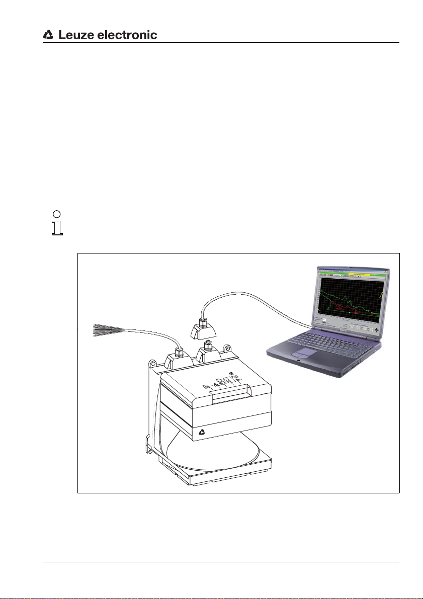
2 Hardware and software installation
2.1 Hardware
2.1.1 Connecting the rotoScan ROD4-3…
To configure the sensor, connect control cable (X1) to the power supply (safety transformer
24V, 2.5A, 1.25A semi-time-lag fuse) and the interface cable (X2) to the PC or notebook.
Before commissioning the system, please check the pin assignments, the wiring, the supply
voltage and the safeguarding. In spite of the sensor's robust housing and fittings, which
include various internal safety mechanisms, damages resulting from misconnection
cannot be excluded.
Notice!
The connection of the ROD4-3… is described here only briefly. Detailed information can be
found in the technical description "Area Scanning Distance Sensor rotoScan ROD4-3…".
Figure 2.1: Connecting the rotoScan ROD4-3…
Leuze electronic RODsoft 5
TNT 35/7-24V
Page 7
Hardware and software installation
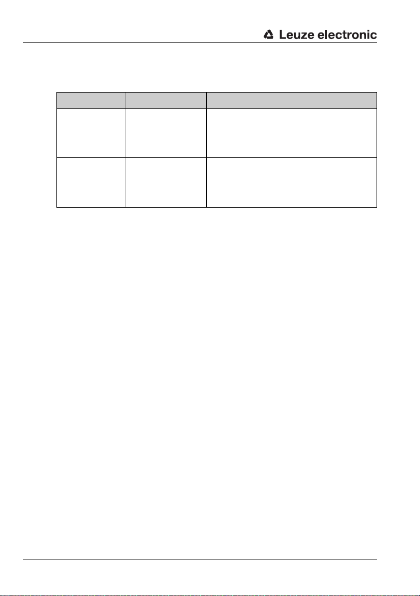
2.1.2 Interface assignment X1 and X2
Interfacees of the rotoScan ROD4-3…
Connection Connector Signals
X1 SUB-D 15-pin
X2 SUB-D 9-pin
Table 2.1: Interfaces X1 and X2
• Power supply
• Switching outputs/alarm output
• Inputs for field pair changeover
• Restart/reset input
• Configuration connector
rotoScan ROD4-3… <–> PC interface
• Parameter configuration
• Detection field definition
• Measurement data transfer
• Diagnosis
6 RODsoft Leuze electronic
Page 8
Hardware and software installation
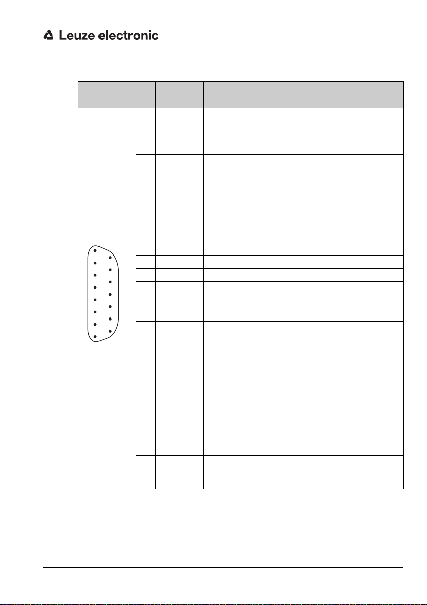
2.1.3 Connector assignments for connection X1
PIN Signal Description Wire colour
1 GND Supply voltage ground black
Safe input "restart-disable", reset of
2 Restart
3 UB Supply voltage +24V DC red
4 FPS1 Changeover of detection field pairs orange
5 ALARM1
8
7
6
5
4
3
2
1
15
6 FPS2 Changeover of detection field pairs green
14
7 FPS3 Changeover of detection field pairs violet
13
8 FPS4 Changeover of detection field pairs grey
12
9 NC Do not use! –
11
10 NC Do not use! –
10
9
11 Fn1
12 Fn2
13 NC Do not use! –
14 NC Do not use! white/brown
15 ALARM2
Table 2.2: SUB-D15 pin assignments for interface X1
the sensor and connection of the
restart button
Output for object detection in the far
detection field and for warning messages such as "Window lightly soiled"
or "Window heavily soiled" (configurable).
4-field mode: Output for object detection in detection field_f 1
Semiconductor output, shutdown on
object detection in the near detection
field, channel 1.
4-field mode: Output for object detection in detection field_n 1
Semiconductor output, shutdown on
object detection in the near detection
field, channel 2.
4-field mode: Output for object detection in detection field_n 2
Warning and error output
4-field mode: Output for object detection in detection field_f 2
KB-ROD4-…
blue
yellow
white
white/black
brown
TNT 35/7-24V
Leuze electronic RODsoft 7
Page 9
Hardware and software installation
1
6
4
3
2
7
8
9
5
6
3
2
7
8
9
5
1
4
Connection
PIN5 to PIN6
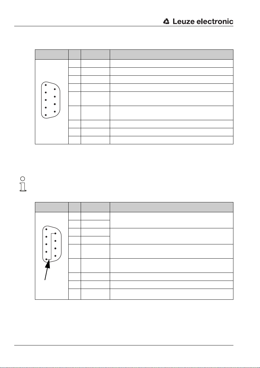
2.1.4 Connector assignments for connection X2 (RS 232)
PIN Signal Description
1 NC Do not use!
2 TxD Data communication, transmission
3 RxD Data communication, reception
4 NC Do not use!
5 GND/shield
6 RS 232
7 NC Do not use!
8 NC Do not use!
9 Reserved Reserved for test purposes, not wired
Table 2.3: SUB-D 9-pin – pin assignments for connection X2 as RS 232 port
2.1.5 Connector assignments for connection X2 (RS 422)
Notice!
If you would like to work with an RS 422 interface, you must connect PIN 6 with PIN 5 (GND)
by means of a bridge.
Ground/shielding (to be connected only on the cabinet
side with PE)
Selection RS 232/RS 422,
selection as RS 232 interface: do not use!
PIN Signal Description
1 TxD+
2 TxD-
3 RxD-
4 RxD+
5 GND/shield
6 RS 422
RS 422 transmitted data
RS 422 received data
Ground/shielding (to be connected only on the cabinet
side with PE)
Selection RS 232/RS 422,
selection as RS 422 interface: bridge to PIN 5!
7 NC Do not use!
8 NC Do not use!
9 Reserved Reserved for test purposes, not wired
Table 2.4: SUB-D 9-pin – pin assignments for connection X2 as RS 422 port
8 RODsoft Leuze electronic
Page 10

2.2 Software
2.2.1 System requirements
• Intel® processor at Pentium® level or faster (or compatible models, e.g. AMD®)
• At least 16 MB RAM
•CD-ROM drive
• Hard disk with at least 30 MB available memory.
• Free RS 232 interface (serial) or alternatively RS 422
•Microsoft
2.2.2 Installation
The supplied installation CD-ROM is required for installing the RODsoft configuration software. Alternatively, the RODsoft configuration software is available for download on the
Internet under http://www.leuze.de
A self-explanatory installation routine is started with the Setup.exe setup program. After the
installation, the program is ready to be started.
®
Windows 95/98/NT/2000/XP
Hardware and software installation
.
Leuze electronic RODsoft 9
TNT 35/7-24V
Page 11
First steps
3 First steps
3.1 General remarks
Attention!
Ensure that the connectors for interfaces X1 and X2 are correctly fabricated and that all cables are correctly connected. Serious, partially irreparable device errors may result if the X1
interface of the rotoScan ROD4-3… is wired incorrectly. If the connector for the X2 interface
is wired incorrectly, the configuration data may either not be transferred at all or only in part.
Also be certain to read the document "Area Scanning Distance Sensor rotoScan ROD4-xx
- Technical Description". It contains important information on working with the RODsoft software.
Notice!
Switch on the power supply of the ROD4-3… before starting the ROD4-3… configuration
software. Data cannot otherwise be received by the device. However, even if the ROD4-3…
is not connected to the PC, you may still define parameters in Offline mode and save them
on the hard disk or evaluate previously stored data.
3.2 Launching the program
To start the RODsoft configuration software, make the following menu selection: Start → All
Programs → Leuze electronic → RODsoft, item RODsoft.
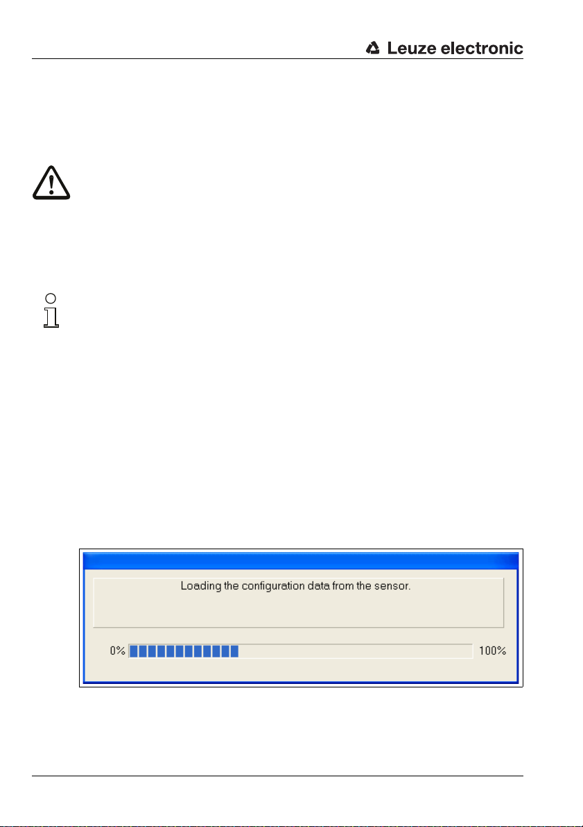
Retrieving configuration data from the ROD4-3…
After starting, your computer – together with the program – establishes a connection to the
rotoScan ROD4-3… and transfers the current configuration data from the ROD4-3… to the
program.
During this process, the following window appears on the screen:
Figure 3.1: Transfer of the current configuration data
10 RODsoft Leuze electronic
Page 12
First steps
Notice!
If this process is not completed successfully, the device is not ready for operation or the connection cable is connected incorrectly.
When starting the software without a ROD4-3… connected, you can still create a configu-
ration offline and save it as a file. Select the Authorized User (AU) access level (password:
ROD4LE) and edit the configuration data using the assistant.
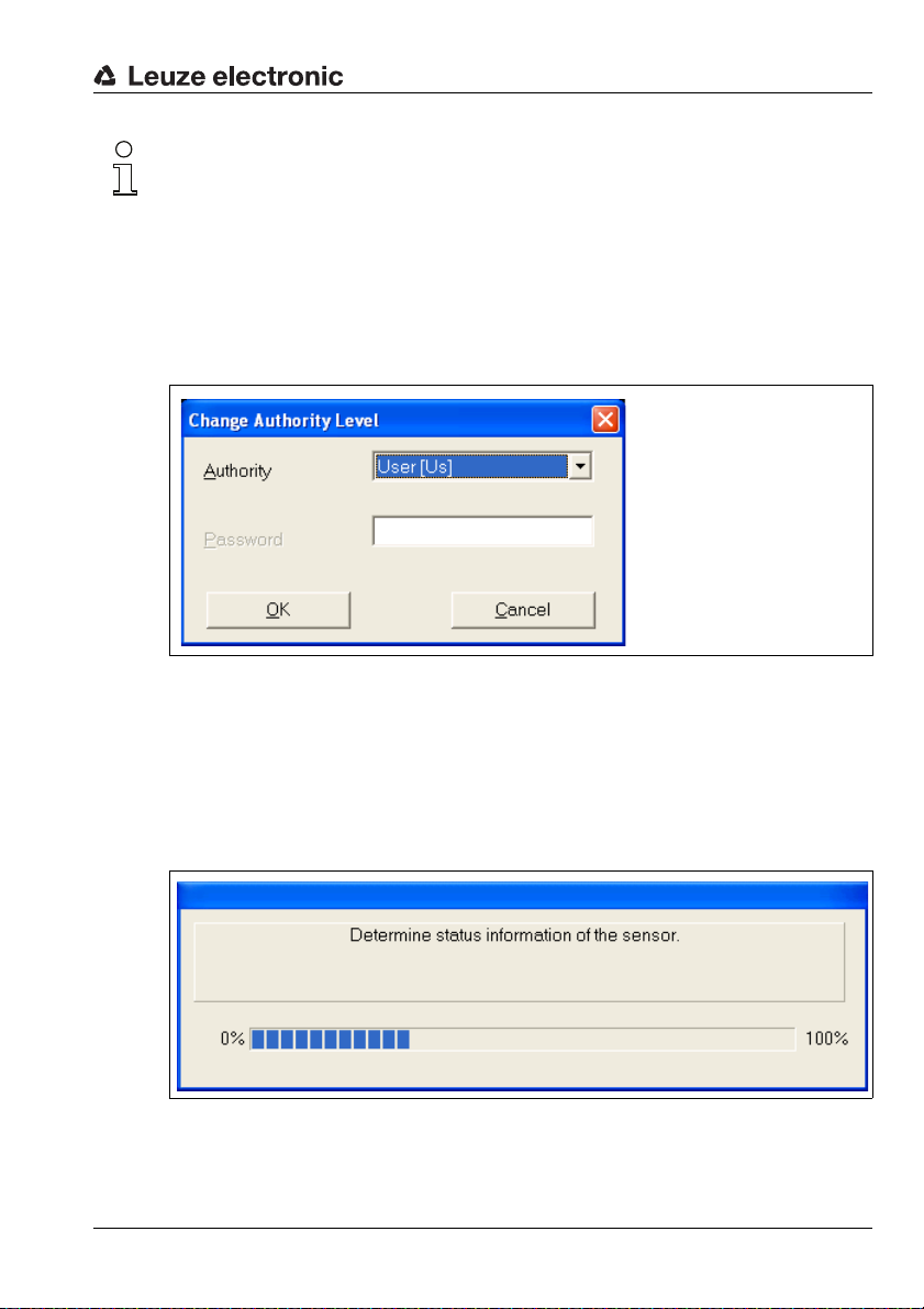
Defining the access level
In the next step, you are prompted by the program to identify your authorisation status by
selecting an access level and entering a password which has been defined for this level.
Figure 3.2: Changing the access level
For the default setting of the "User" access level, no password is required.
As User, you can display measurement values. Configuration parameters and detection
fields cannot be changed (see chapter 4.5).
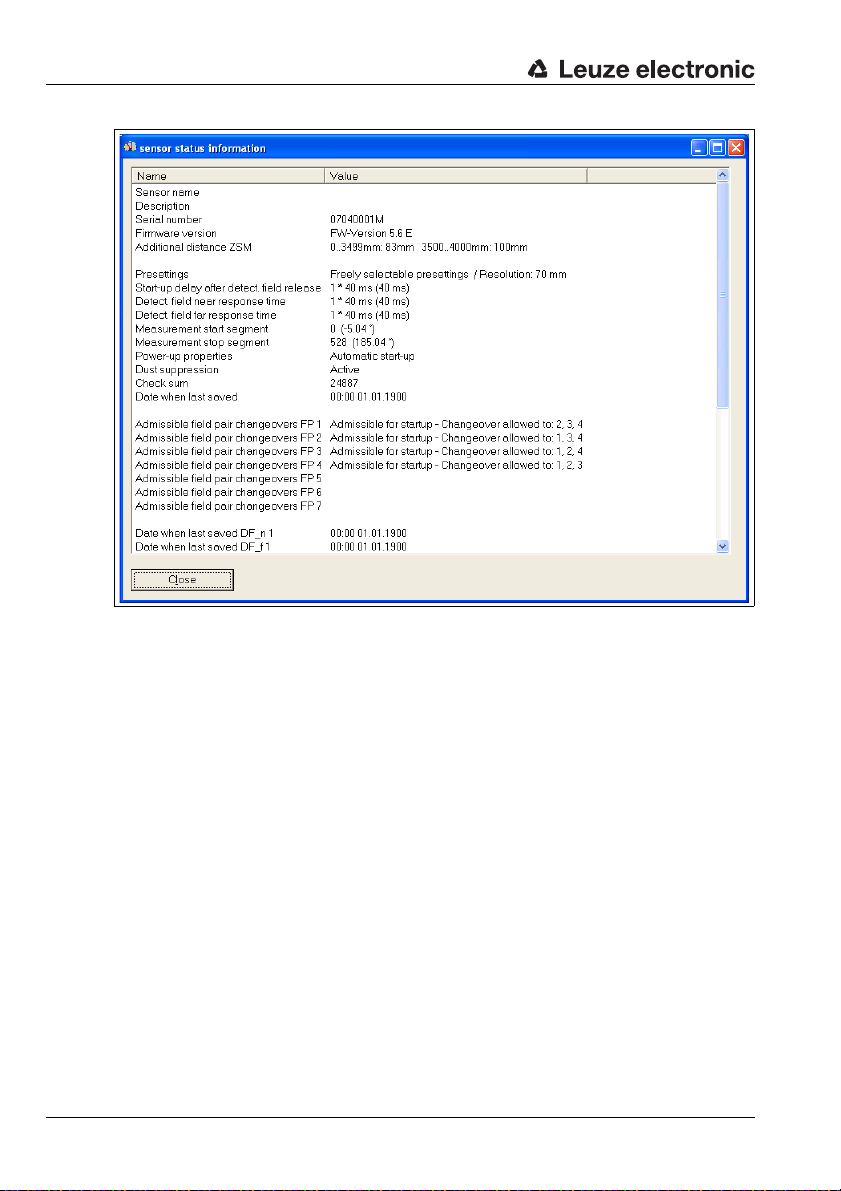
ROD4-3…Status information
If your access authorisation was accepted, the ROD4-3… status information is read in and
displayed in a window.
Figure 3.3: Reading in the status information
Leuze electronic RODsoft 11
TNT 35/7-24V
Page 13
First steps
Figure 3.4: ROD4-3…Status information
12 RODsoft Leuze electronic
Page 14
User interface of the program
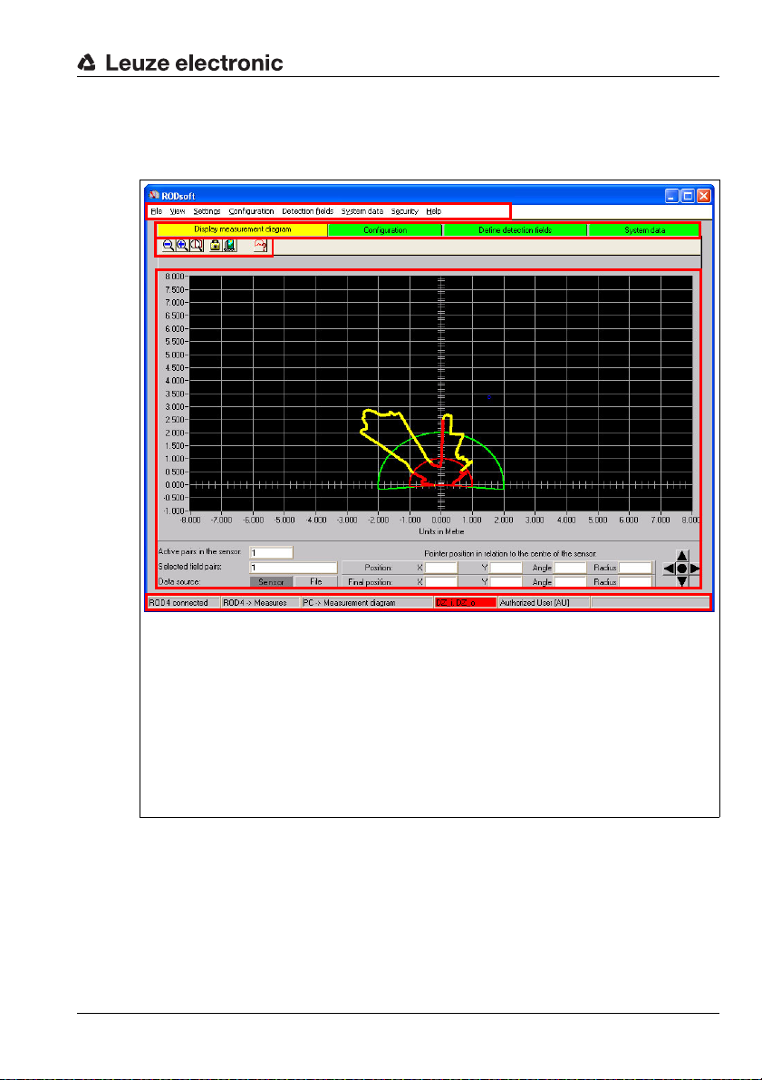
1
2
3
4
5
1
Menu bar
2
Tab with the 4 work areas:
• Display measurement diagram (active = yellow)
• Configuration
• Define detection fields
• System data
3
Tab-dependent function buttons
4
Graphic work area
5
Status bar
After you close the window which contains the sensor status information, the user interface
of the configuration software appears in the foreground:
First steps
Figure 3.5: RODsoft user interface
Leuze electronic RODsoft 13
TNT 35/7-24V
Page 15

First steps
3.3 Procedure / work areas
With RODsoft, you can work both online (with connected sensor) as well as offline
(without connected sensor). To change the work area, click the appropriate tab. The active
tab is displayed in yellow.
Typical procedure
• Connect sensor and start program. The current configuration data are loaded by the
sensor.
• Select the Authorized User (AU) access level (password: ROD4LE).
The status information is loaded by the sensor.
• Edit the sensor configuration and define detection fields.
• Transfer new configuration to the sensor and back up the data by saving to a file.
• Test new configuration in measurement operation.
"Display measurement diagram" tab
Measurement operation is activated; the environment is scanned and the contours of
objects present in the measurement range are displayed in yellow. The current detection
fields are displayed here in red (near detection field) or green (far detection field).
"Configuration" tab
All functions necessary for configuring the sensor and setting parameters are available here.
The sensor configuration can be edited with the aid of the Configuration Wizard or directly
in the parameter tree structure. The configuration data can be loaded by the sensor or from
a file and saved to either the sensor or as a file.
For documentation purposes, the current configuration can be printed or saved as a text file.
In this work area, the sensor can be reset to standard configuration values (factory setting).
"Define detection fields" tab
This work area supports the application-specific definition of up to 7 detection field pairs. The
detection fields can be taught, created interactively with the mouse using the graphical interface or entered numerically. Detection fields which have already been defined can be
changed, faded out or borders cut on a segment-by-segment basis.
By defining a reference boundary, not only is the active near detection field monitored, but
the exact measurement values are also compared with the reference boundary.
Detection fields can be deleted, saved in the sensor or as a file and printed out.
"System data" tab
This work area is used primarily for device identification and diagnostics. Status information
and diagnostic data can be loaded by the sensor. A service file can be created which
contains all information necessary for diagnosing the sensor.
In addition, adjustment of the front window sensor can be performed here (e.g. following an
exchange) and the sensor can be reset.
14 RODsoft Leuze electronic
Page 16
Description of the user interface
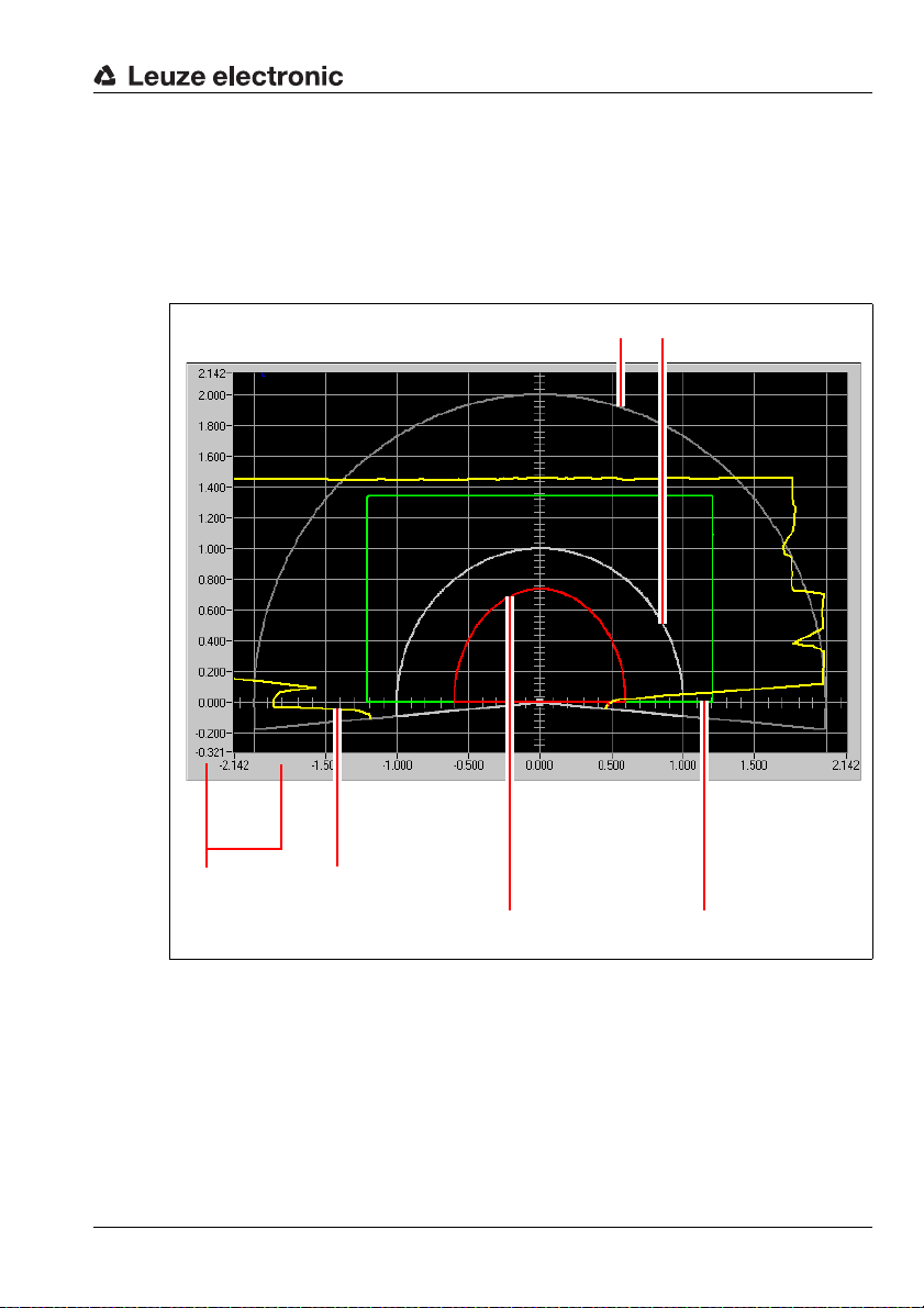
Rulers Measurement value
display (yellow)
Active detection field
near (red)
Active detection field
far (green)
Inactive detection fields (grey)
4 Description of the user interface
4.1 Graphical work area / detection fields
Various components comprise the actual graphical work area of the program. The work area
serves primarily for reading the measurement values and defining the detection fields.
Figure 4.1: Objects on the work area
Rulers
"Meter" is the unit of measurement used for the rulers. When you zoom, the gradations on
the rulers change appropriately for the given zoom level.
Leuze electronic RODsoft 15
TNT 35/7-24V
Page 17
Description of the user interface
Displaying measurement values
In the "Display measurement diagram" tab, you can view the current measurement values
of the sensor as a yellow curve. The laser in the device scans the environment at a scanning
rate of 25Hz. If an object enters the scanning area, it is therefore detected by the laser within
no more than 40ms. In the display, the object is displayed simultaneously with the detection
by the laser.
Notice!
The display of the measurement values on the screen corresponds to the alignment of the
ROD4-3…. If a person or object e.g. in the view direction of the ROD4-3… enters the scanning area from the right, the measurement line changes at the right.
You can, however, also rotate the graphical work area by 180°.
In the "Configuration" and "System data" operating modes, the last measurement contour
measured prior to switching to the given operating mode is frozen on the screen.
Detection fields / detection field pairs
Eight reversible detection field pairs (7 configurable + 1 permanently defined) enable optimal
adaptation to the applications. A detection field pair is considered to be the combination of
both a near and far detection field. The following designations are used in the RODsoft
configuration software:
Detection field pair x consists of detection field_n x (near) and detection field_f x (far).
The near and far detection fields are represented by different colours in the RODsoft configuration software: near = red, far = green.
Detection field pairs 1 … 7 can be freely defined by the user. Detection field pair 8 is permanently defined. Both detection field_n 8 as well as detection field_f 8 are set to zero here.
This means that no area monitoring takes place when detection field pair 8 is activated, and
the respective outputs are switched on.
The near detection fields (1 … 7) can be defined with a radius of up to 30m; the far detection
fields (1 … 7) can be defined with a radius of up to 50m.
4.1.1 Changing over between detection field pairs
Attention!
Depending on which detection field pairs are configured, 1 or 2 detection field pairs
may be simultaneously active and simultaneously monitored!
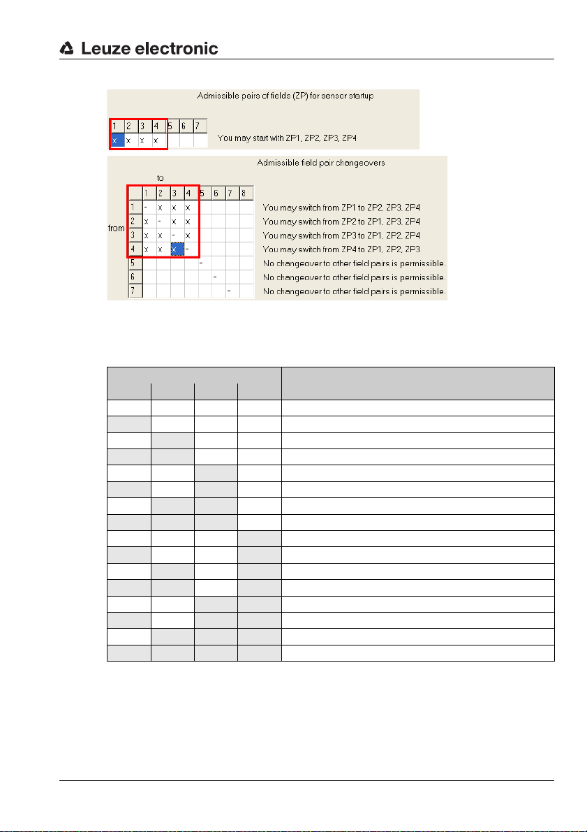
Only detection field pairs 1 through 4 are configured
If only detection field pairs 1 through 4 are configured in the RODsoft configuration software,
i.e. it is only possible to start with a field pair between 1 and 4 and it is only possible to
changeover between a field pair between 1 and 4, then a maximum of 2 detection field pairs
may be simultaneously active and monitored.
16 RODsoft Leuze electronic
Page 18
Description of the user interface
Figure 4.2: Configuring detection field pairs 1 through 4 only
The four control inputs FPS1 … FPS4 can be used to change over between the detection
field pairs. The following table shows the admissible control options.
Control input
FPS1 FPS2 FPS3 FPS4
0000 Detection field pair 1 is active
1000 Detection field pair 1 is active
0
1 100 Detection field pairs 1 and 2 are active
00
1010 Detection field pairs 1 and 3 are active
0
1 1 1 0 Not permitted
000
1001 Detection field pairs 1 and 4 are active
0
1 101 Not permitted
00
101 1 Not permitted
0
1 1 1 1 Not permitted
Table 4.1: Changeover of the detection field pairs via the control inputs
If an inadmissible state exists at the control inputs for more than 80 ms, the sensor switches
to the error state.
100 Detection field pair 2 is active
10 Detection field pair 3 is active
1 10 Detection field pairs 2 and 3 are active
1 Detection field pair 4 is active
101 Detection field pairs 2 and 4 are active
1 1 Detection field pairs 3 and 4 are active
1 1 1 Not permitted
Meaning
TNT 35/7-24V
Leuze electronic RODsoft 17
Page 19
Description of the user interface
One of detection field pairs 5 through 8 is also configured
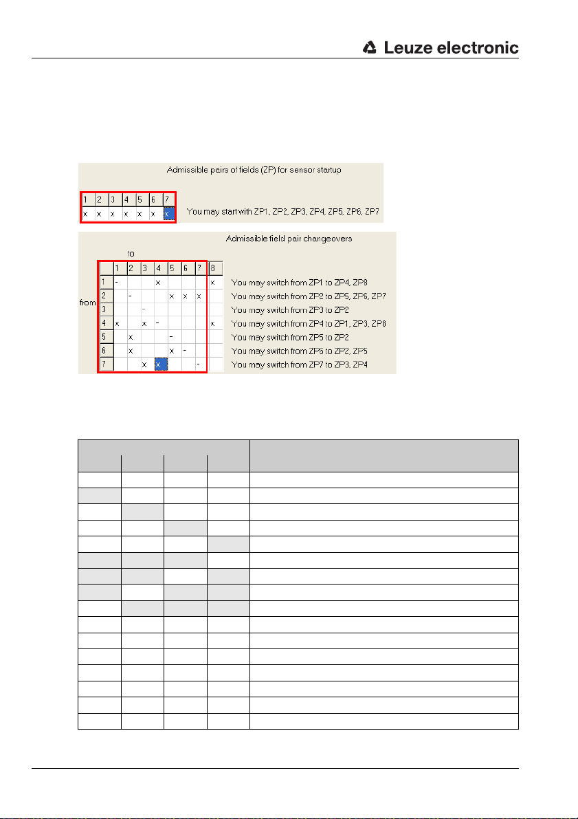
If, in addition to detection field pairs 1 through 4, at least one of detection field pairs 5 through
8 is also configured in the RODsoft configuration software, i.e. it is possible to start with a
field pair between 1 and 7 and/or it is possible to changeover between a field pair between
1 and 8, then only 1 detection field pair may be simultaneously active and monitored.
Figure 4.3: Also configuring detection field pairs 5 through 8
In this case, the four control inputs can be used to change over between the detection field
pairs as follows.
Control input
FPS1 FPS2 FPS3 FPS4
0000 Detection field pair 1 is active
1000 Detection field pair 1 is active
0
00
000
1 1 10 Detection field pair 5 is active
1 101 Detection field pair 6 is active
101 1 Detection field pair 7 is active
0
1100 Not permitted
1010 Not permitted
0110 Not permitted
1001 Not permitted
0101 Not permitted
0011 Not permitted
1111 Not permitted
Table 4.2: Changeover of the detection field pairs via the control inputs
100 Detection field pair 2 is active
10 Detection field pair 3 is active
1 Detection field pair 4 is active
1 1 1 Detection field pair 8 is active
Meaning
18 RODsoft Leuze electronic
Page 20
While changing over between 2 detection field pairs, inadmissible states at the control inputs
are tolerated for a duration of 40ms; after this period the sensor switches to the error state.
The changeover between 2 detection field pairs occurs within a system reaction time of
80ms.
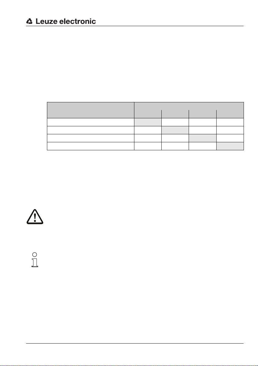
4.1.2 4-field mode
In 4-field mode (configuration via RODsoft), all 4 detection fields of detection field
pairs 1 and 2 are simultaneously activated and evaluated. In this case, a separate output is
assigned to each detection field pair.
Detection field
Detection field_n 1
Detection field_n 2
Detection field_f 1
Detection field_f 2
Table 4.3: Assignment of detection field to switching output in 4-field mode
Inputs FPS1 … FPS4 are not evaluated in 4-field mode. Detection field changeover is not
possible in 4-field mode.
The 4-field mode is activated:
• in the configuration assistant under Presettings or
• using the menu command Configuration –> Change –> Configuration Parameters
–> Presettings.
Description of the user interface
Switching output
Fn1 Fn2 ALARM1 ALARM2
X
X
(X)
X
Attention!
Depending on the configuration, output ALARM1 may, in some cases, also signal device
warnings. This means that a violation of detection field_f 1 is not uniquely signalled under
certain circumstances.
All outputs are switched off during start-up. Outputs ALARM1 and ALARM2 are activated
during configuration.
Notice!
Operation with 3 detection fields
If only three detection fields are to act on three outputs, only use detection field_n 1, detection field_n 2 and detection field_f 2 and set the alarm signal type for ALARM1 to "Device
warning". The output ALARM1 will then only signal device warnings and is, as a result,
unique.
Operation with 2 detection fields
If only two or fewer independent outputs are needed, 4-field mode is not required and should
be deactivated with the appropriate RODsoft parameter.
Leuze electronic RODsoft 19
TNT 35/7-24V
Page 21
Description of the user interface
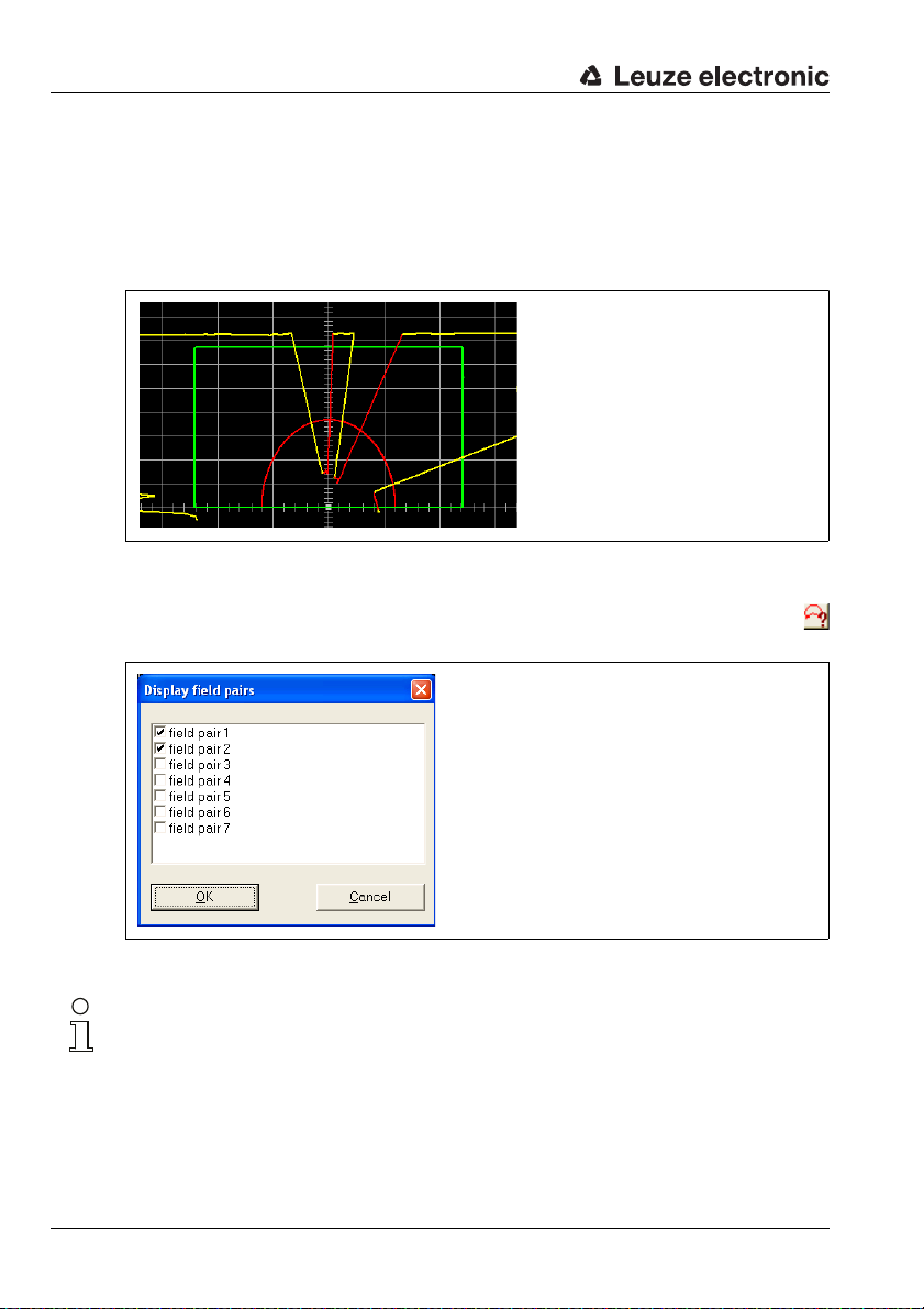
4.1.3 Displaying measurement diagram/detection fields
In "Display measurement diagram", you can always see if an object is approaching the
respective detection field or if an object has been detected within a detection field (the yellow
measurement contour enters the green or red area, see figure 4.4). If the entering of the
object into an active near detection field leads an object detection, the measurement contour
is coloured red at this position.
Figure 4.4: Object detection within the detection fields
If you would like to monitor only one detection field pair on the screen, you can fade out the
other detection field pairs using the Settings –> Display field pairs menu item or the
icon in the "Display measurement diagram" operating mode.
Figure 4.5: Selection of the detection field pair to be displayed
Notice!
Displaying/hiding a detection field in RODsoft has no effect on how it is monitored by the
sensor! Only after a detection field pair is activated via the control inputs is it monitored by
the sensor.
You can adapt detection fields to your application by editing them in the "Define detection
fields" operating mode (see chapter 6).
20 RODsoft Leuze electronic
Page 22
4.2 Tabs and toolbar
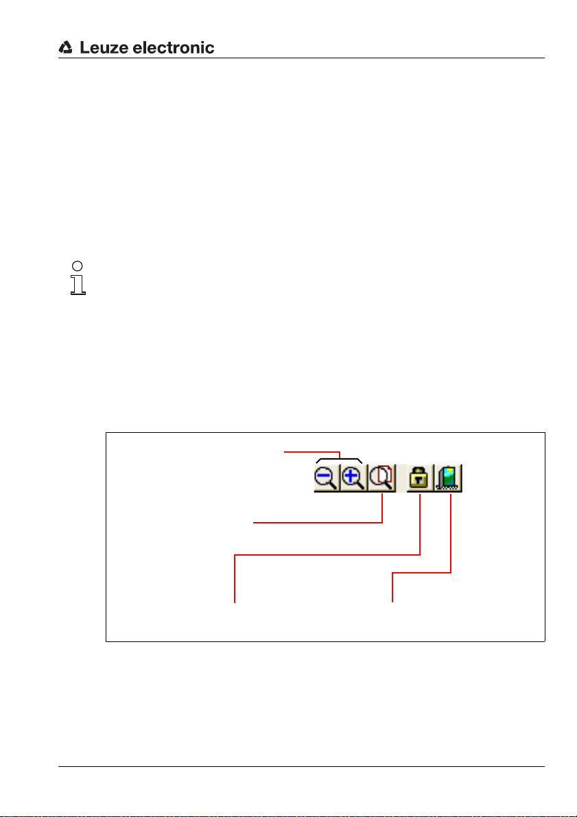
Changing the access level Exit program
RODsoft
Zoom
(display smaller/larger)
Zoom
(display complete
diagram area)
4.2.1 Tabs
To simplify work with the RODsoft configuration program, the software interface is divided
into 4 work areas (see chapter 3.3).
These work areas correspond to the four operating modes in the Settings –> Operating
mode menu and are displayed as tabs. Each tab or operating mode has a toolbar of its own.
How the detection field values are displayed is dependent on the selected operating mode.
You can select the operating mode either by Clicking the respective tab or with the
Settings –> Operating mode menu item.
Notice!
Depending on the adjustments made previously in a given operating mode, you may, under
certain circumstances, be prompted to update the data with the sensor before switching to
a different operating mode.
4.2.2 Buttons
The buttons in the toolbar serve as a shortcut to commands which can also be selected from
the menu bar.
General buttons
The following figure shows the general buttons, which are available in all 4 work areas:
Description of the user interface
Figure 4.6: General buttons
Leuze electronic RODsoft 21
TNT 35/7-24V
Page 23
Description of the user interface
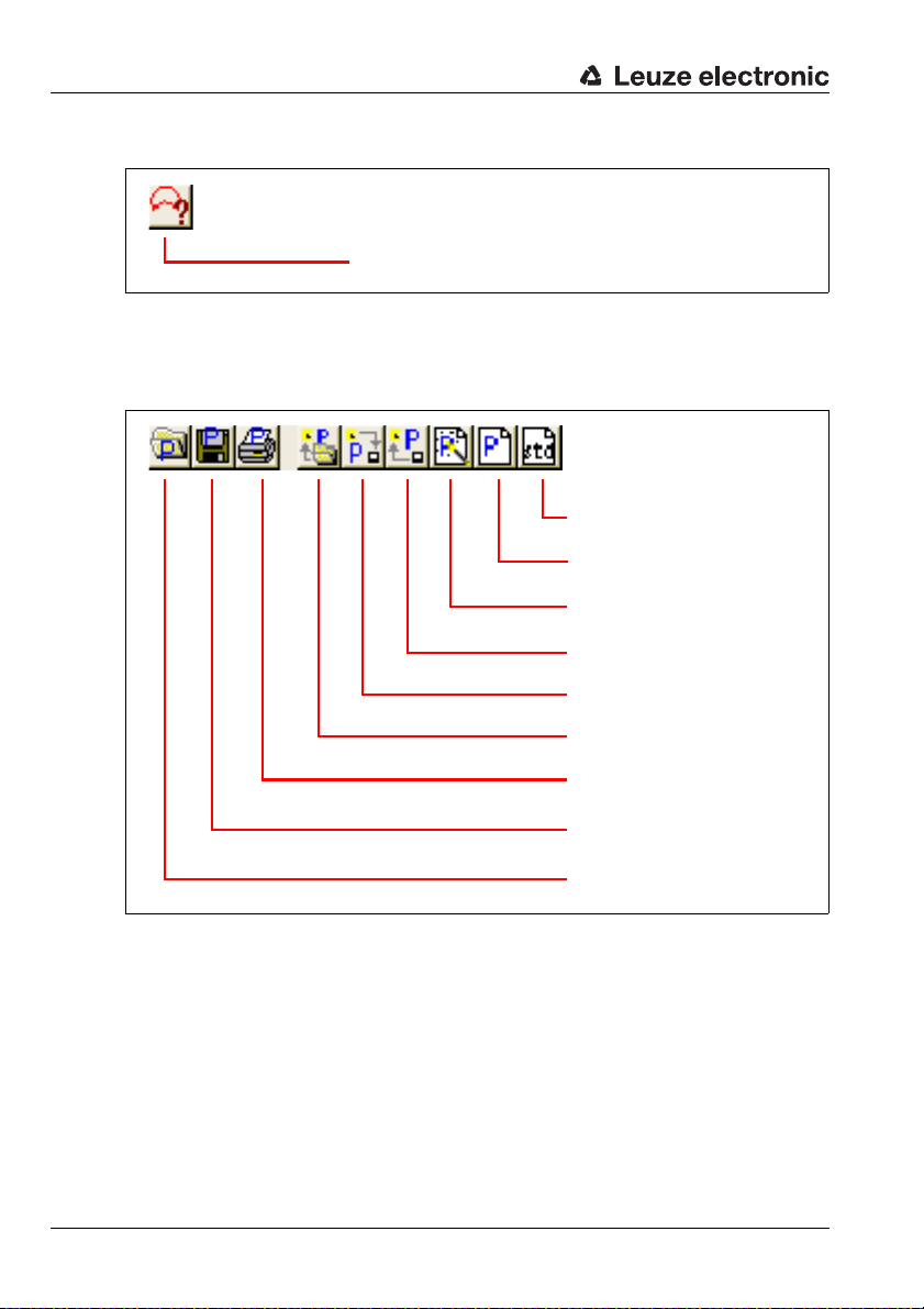
Selection of the detection
field pairs to be displayed [1,2,3,4,5,6,7]
Set default values in the sensor
(state on delivery)
Change configuration data
(tree structure)
Call up Configuration Wizard
Transfer configuration data from the
PC to the sensor
Get configuration data from the sensor
Load configuration file from data carrier and transfer to the sensor
Print current configuration data
Save current configuration to file
Load configuration from file
Additional buttons in the "Display measurement diagram" operating mode
Figure 4.7: Specific icon in the "Display measurement diagram" operating mode
Additional buttons in the "Configuration" operating mode
Figure 4.8: Additional buttons in the "Configuration" operating mode
22 RODsoft Leuze electronic
Page 24
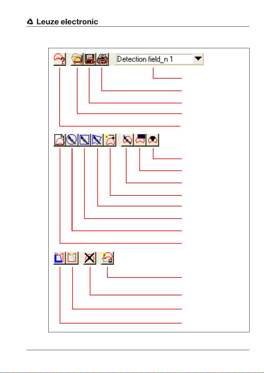
Description of the user interface
Selection of the detection field to
be edited
Print detection
field
Save detection field to file
Load detection field from file
Selection of the detection field
pair to be displayed
Fade out detection field segment
Cut detection field
Change detection field
segment
Teach-in detection field
Define polygonal detection field
Define rectangular detection
field
Define elliptical detection field
Input detection field numerically
Transfer modified detection
fields from the PC to the sensor
Delete detection field
Reset reference boundary definition of detection field segment
Set detection field segment as
reference boundary
Additional buttons in the "Define detection fields" operating mode
Figure 4.9: Additional buttons in the "Define detection fields" operating mode
Leuze electronic RODsoft 23
TNT 35/7-24V
Page 25
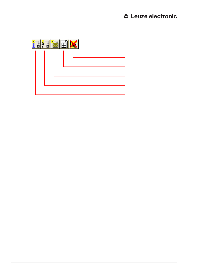
Description of the user interface
Reset sensor (restart)
Adjust optical window supervision
Create service file
Load diagnostic data from the
sensor
Load status information from the
sensor
Additional buttons in the "System data" operating mode
Figure 4.10: Additional buttons in the "System data" operating mode
24 RODsoft Leuze electronic
Page 26
4.3 The menu bar
All program commands are located in various menus.
Notice!
Some menu items can only be selected if you are in the appropriate tab (work area).
How the individual commands are used is described in detail in the following chapters. The
commands located in the menus are described briefly in the following overview.
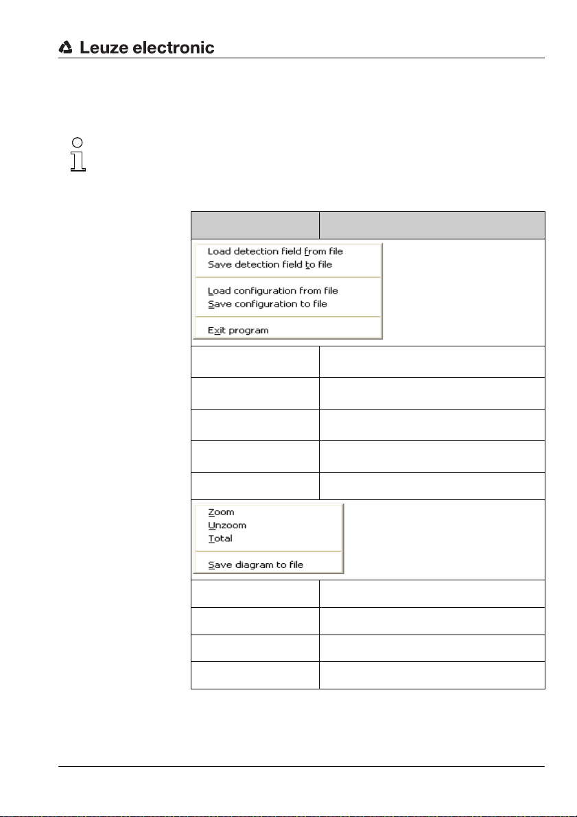
File menu
Description of the user interface
Command Function
View menu
Load detection field
from file
Save detection field to
file
Load configuration
from file
Save configuration to
file
Exit program Exit RODsoft
Zoom Enlarge view
Unzoom Reduce view
Tot al View to 100%
Save diagram to file Save active view as bitmap
Load saved detection fields
Save active detection field definition
Load stored configuration
Save active configuration
TNT 35/7-24V
Leuze electronic RODsoft 25
Page 27
Description of the user interface
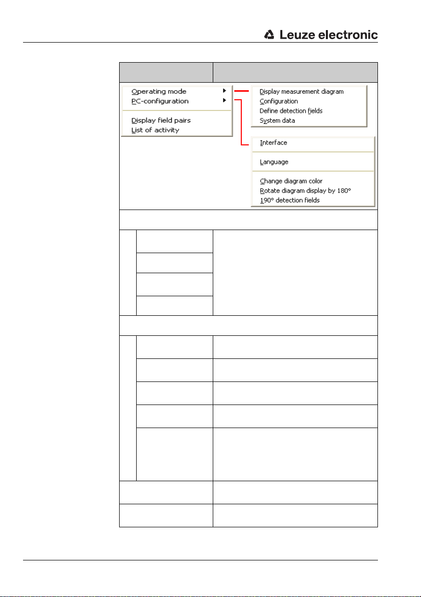
Command Function
Settings menu
Operating mode
Display measurement diagram
Configuration
Define
detection fields
System data
PC-configuration
Interface
Language
Change diagram
color
Rotate diagram
display by 180°
190°
detection fields
Display field pairs
List of activity
Switch between the four work areas (tabs)
Selection and configuration of the serial interface
Selection of the language version
(German / English) → expandable
Selection of the background colour
(black/white)
Rotate the entire diagram area by 180°
If this function is activated, expansion of the
detection field definition by an additional 10°
is enabled, i.e. from 180° to 190 °. Measurement value acquisition itself is not affected by
this.
Selection of the visible detection field pairs (1/
2/3/4/5/6/7)
Display program activities with date and time
in a separate window
26 RODsoft Leuze electronic
Page 28
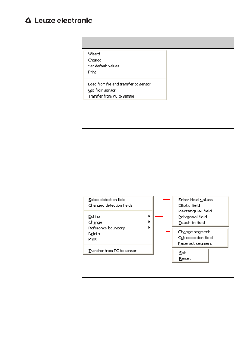
Configuration
menu
Detection fields
menu
Description of the user interface
Command Function
Wizard Start the Configuration Wizard
Change
Set default values in the
sensor
Print Print the current configuration
Load from file and
transfer to sensor
Get from sensor
Transfer from PC to
sensor
Change the configuration parameters
(tree structure)
The sensor is reset to the state upon delivery
(standard configuration)
Load a saved configuration file from a data
carrier and transfer to the sensor
Transfer configuration data from the sensor to
RODsoft
Transfer configuration data from RODsoft to
the sensor
Select detection field Selection of the detection field to be edited
Changed detection
fields
Define
Leuze electronic RODsoft 27
Displays the changed detection fields which
have not yet been transferred to the ROD43…
TNT 35/7-24V
Page 29
Description of the user interface
Command Function
Enter field values
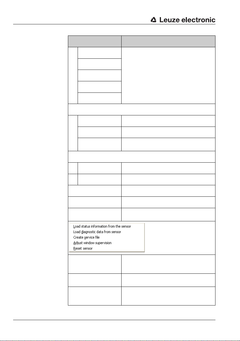
System data
menu
Elliptic field
Rectangular field
Polygonal field
Teach-in field
Change
Change segments Edit selected detection field
Cut detection field Cut sides of the selected detection field
Fade out segment
Reference boundary
Set Define a reference boundary
Reset Remove a reference boundary
Delete Delete selected detection field
Print Print selected detection field
Transfer from PC to
sensor
Use corner points, ellipse, rectangle, polygon
and measurement contour to edit a detection
field
Remove individual segments of the selected
detection field
Send newly defined/changed detection fields
to the ROD4-3…
Loading status information from the sensor
Loading diagnostic
data from the sensor
Create service file
28 RODsoft Leuze electronic
Call up status information (parameter overview) from the sensor and display in a separate window
Display the last ROD4-3…-device errors
Create a service file with all device information and parameters necessary for remote
diagnostics
Page 30
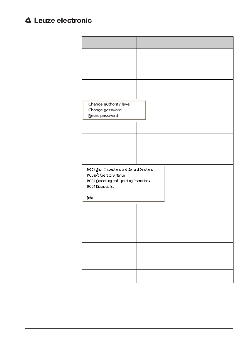
Security menu
Help menu
Description of the user interface
Command Function
This function is used for calibrating the front
Adjust window supervision
Reset sensor
Change access level Change access level
Change password Change password for the access level
Reset password
cover sensors following replacement of the
front cover. A special password, provided by
the Leuze service department, is required in
order to use the function.
This function sends a reset command to the
sensor (e.g. if no RESTART button is provided
and a device error has occurred).
If the "password is forgotten": displays the
password as an encrypted number to be sent
to LEUZE customer service for reactivation.
ROD4 Short Instructions and General
Directions
RODsoft
Operator's Manual
ROD4 Connecting and
Operating Instructions
ROD4Diagnostic list
Info
1) Adobe Acrobat Reader required
Displays a PDF file with short instructions and
general directions for using the ROD4-3…
1)
Displays the PDF version of the RODsoft
Software and Protocol Description
(this document)
Displays the PDF version of the technical
description ROD4-3…
Displays a PDF file with explanations of the
diagnostic codes
1)
1)
1)
Version information on the configuration software RODsoft
Table 4.4: Overview of the menu commands
Leuze electronic RODsoft 29
TNT 35/7-24V
Page 31

Description of the user interface
Current access
level
Connection
status
Currently selected
work area
Object detection in
the far (green) or near
(red) detection field
Operating state
of the sensor
4.4 Displaying status information
4.4.1 Data source
Figure 4.11: Display of data source for configuration data
The fields display the source of the configuration data, i.e. the source from which the current
configuration data were loaded or the location to which they were most recently written.
• "Sensor" field active (dark):
Data were loaded from or saved in the sensor.
• "File" field active (dark):
Data were loaded from or saved as a file.
• No field active:
Configuration data have not yet been loaded or saved, e.g. if the program was started
before the sensor was ready.
Notice!
The display also changes if only parts of the configuration data are loaded or saved (e.g.
only one detection field).
4.4.2 Status bar
Important information on the current hardware and software states are displayed in the
status bar:
• Connection status between sensor and PC
• Current operating state of the sensor
• State of the inputs and outputs
• The current access level
Figure 4.12: Status bar
The first field contains the operating state of the sensor. Following successful synchronisation of PC and sensor, the text of the info field changes from "ROD4 synchro" to "ROD4
connected".
30 RODsoft Leuze electronic
Page 32

The following field displays the operating mode (measurement operation) and any possible
error messages. In the next field, the active work area (operating mode) of the program is
displayed. The fourth field displays an object detection in one of the detection fields, far
(green) and/or near (red). In the last field, the currently selected access level (see chapter
4.5) is displayed:
•User [Us]
• Maintenance [Ma]
• Authorized User [AU]
• Production [Pr]
• Development [De]
4.5 Access levels
In order to ensure that the device is configured only by trained and authorised persons,
RODsoft provides different functionality for different access rights in the "Change Access
Level" dialogue.
Description of the user interface
Figure 4.13: Changing the access level
Access levels and access rights
Registration is by means of predefined access levels, each of which is protected against
unauthorised access by means of a password. In the "Authorized User" access level, detection fields can also be created "off-line", i.e. without a connected ROD4-3…. These detection
fields can then, for example, be stored on diskette.
The following access levels are available:
Leuze electronic RODsoft 31
TNT 35/7-24V
Page 33

Description of the user interface
I
Level (abbr.) Password Access
User (Us) No password
Maintenance (Ma) ROD4/GOY
Authorized User (AU) ROD4LE Full access to all functions
Production (Pr) Manufacturer-specific access
Development (De) Manufacturer-specific access
Table 4.5: Access levels and passwords
Passwords may be entered in either upper- or lower-case letters. No changes can be made
to the device configuration in the "User" access level. This level is, therefore, not password
protected. All functions which are not permitted in the given access levels are faded out in
grey. The current access level is displayed in the status display. (see section 4.4.2 "Status
bar").
Notice!
The password set at the factory for Authorized User (AU) is "ROD4LE". When configuring
the rotoScan ROD4-3… for the first time, the employee responsible for (Ma) and (AU) is to
define new passwords, save them and store the data carriers in a safe location.
General program settings, display and analysis
of measurement values, loading the current
ROD4-3… configuration data to the PC.
Changes cannot be made to the configuration
data!
Device configurations can be loaded from a diskette and stored in the ROD4-3….
Changes cannot be made to the configuration
data!
Figure 4.14: Notice for password changes
Changing the password
To change the password, select the Change password command from the Security menu.
In the following dialogue, enter a new password and repeat the entry to ensure correctness.
Confirm the entry with OK.
32 RODsoft Leuze electronic
Page 34

Description of the user interface
Figure 4.15: Changing the password
Attention!
→
If the password is no longer known, select the Security
Resetting the password
After actuating the Generate button, a security password is generated and displayed in red
text.
Reset password menu item.
Figure 4.16: Resetting the password
This is to be sent by either fax or mail to Leuze electronic together with the complete address
of the company, the user name and the sensor serial number. You will immediately receive
a confirmed single password which is to be entered in the "Set new password" dialogue.
Leuze electronic RODsoft 33
TNT 35/7-24V
Page 35

Description of the user interface
Figure 4.17: Confirming the single password
After the new password has been entered in both fields, access is restored to the sensor in
the "Authorized User (AU)" level.
If the confirmed single password is entered incorrectly, the sensor indicates an error
message by means of LED no. 5. Furthermore, a corresponding error message is displayed
on the screen after approx. 2 minutes. Please note that during this period RODsoft is disabled and no entry is possible.
Changing the access level
If you would like to change your access level during operation, select the Security →
Change access level menu item or click the icon, which is visible in all four toolbars. In
the following dialogue window, change to the desired level, enter the required password and
confirm the process with OK.
Figure 4.18: Changing the access level
34 RODsoft Leuze electronic
Page 36

4.6 Program settings
4.6.1 Configuring the serial interface
Use the Settings –> PC-configuration –> Interface menu item to set the serial interface
(COM…) and desired transmission rate in baud (bit/s) which are to be used.
Figure 4.19: Configuring the serial interface
4.6.2 Setting the program language
Use the Settings → PC-Configuration → Language menu item to select the program
language. Select between German, English, French and Italian.
Description of the user interface
Figure 4.20: Setting the program language
Notice!
A change of the language selection does not take effect until the program is restarted.
Leuze electronic RODsoft 35
TNT 35/7-24V
Page 37

Description of the user interface
4.6.3 Selecting the background colour
To better recognise the measurement curves (yellow), it is recommended that the background colour be set to black (default). On the other hand, when creating the detection fields,
white is better suited. To select between these two colours, select the Settings –> PC-
configuration –> Change diagram color menu item.
36 RODsoft Leuze electronic
Page 38

Editing / configuring the device configuration
5 Editing / configuring the device configuration
5.1 General information and procedure
Initial configuration
• Carefully study the guidelines and standards which apply to your application. For
information, refer to the "Safety information" chapter in the rotoScan ROD4-3… technical description.
• Start your PC with all necessary peripheral devices - without connecting the sensor.
• Install RODsoft.
• When unpacking the rotoScan ROD4-3…, avoid touching the front cover and the window monitoring sensors.
• Connect the rotoScan ROD4-3… via connector X1 accordance with the instructions.
• Connect the rotoScan ROD4-3… to the PC via connector X2 in accordance with the
instructions.
• After applying the operating voltage, the sensor indicates communication readiness
after approx. 10s. This is indicated by the message "ROD4 connected" on the screen.
• The predefined detection field pairs are, due to the factory settings, superimposed
upon one another; each pair is therefore only visible as a single contour. Only one
detection field pair is activated and displayed in colour at any one time.
• Please observe the specifications for the voltage supply in the rotoScan ROD4-3…
technical description.
• Take note of any objects detected on the basis of the predefined detection fields.
Changing a configuration or a detection field
• Note, that before making changes, error-free data communication must be possible.
This is indicated on the screen by the status message "ROD4 connected".
• Changes are only possible in the "Authorized User (AU)" access level and above.
• In addition, changes are only possible if a configuration is also loaded in the PC. This
can be performed via the hard disk or via the sensor.
• Changes to a configuration are accepted by RODsoft only following successful
acknowledgement (Accept or OK button).
• Changes take effect only after successful data transmission to the sensor.
• If detection fields are loaded as a file, e.g. from the hard disk, the plausibility of the
sensor configuration is to be checked.
• The safety notices in the rotoScan ROD4-3… technical description must be observed.
Leuze electronic RODsoft 37
TNT 35/7-24V
Page 39

Editing / configuring the device configuration
Creating a configuration without a connected sensor
• After calling up RODsoft, the "Authorized User (AU)" access level is to be selected.
• The measurement field is first displayed without measurement contours.
• Enter the password for the respective user level.
• A configuration file can be loaded into the PC from the hard disk. The file extension is
*.rs.
• Please note that the configuration files contain sensor configurations and detection
field definitions.
• A detection field file can be loaded into the PC from the hard disk.
The file extension is *.sf.
• Note that detection field files do not contain sensor configurations.
• Stored files can be loaded into the sensor.
38 RODsoft Leuze electronic
Page 40

Editing / configuring the device configuration
5.2 Current sensor configuration
Retrieving the configuration
If the ROD4-3… is connected to the PC on program start, the current parameters are automatically transferred from the device to the PC. This also occurs if the device was temporarily not connected to the PC (e.g. exchanging the device) and is detected by the program
as again being present on the serial interface.
If you have made changes to the configuration and have not transferred the previous configuration to the device, you have the option of manually loading the configuration stored in the
ROD4-3….
To do this, on the menu bar select the Configuration → Get from sensor menu item or
click the icon in the "Configuration" tab. The current device configuration will then be
read back in.
Attention!
Before making changes, store the current configurations! These can be used in the event of
incorrectly entered parameters to restore the original settings.
Information on storing configurations can be found in chapter 5.4.
5.3 Changing configuration parameters
Notice!
The device configuration can only be viewed and edited in the "Authorized User" access level.
In principle, there are 2 possibilities for editing the configuration data of the sensor:
• with the Configuration Wizard, which guides you step-by-step through the entry of
the most important parameters.
•directly in the tree structure for the parameters in the Configuration Parameters
window
5.3.1 Configuration Wizard
With the aid of the Configuration Wizard, you can edit the sensor's most important parameters. The parameters and their possible values will be explained in detail.
To start the Configuration Wizard,
• select the "Configuration" tab and then the
Configuration -> Wizard menu item or
• click the icon on the "Configuration" tab toolbar.
Leuze electronic RODsoft 39
TNT 35/7-24V
Page 41

Editing / configuring the device configuration
Figure 5.1: Configuration Wizard, pages 1 and 2
40 RODsoft Leuze electronic
Page 42

Editing / configuring the device configuration
b
Figure 5.2: Configuration Wizard, page 3
Leuze electronic RODsoft 41
TNT 35/7-24V
Page 43

Editing / configuring the device configuration
Figure 5.3: Configuration Wizard, pages 4 and optional page 4a
42 RODsoft Leuze electronic
Page 44

Editing / configuring the device configuration
Figure 5.4: Configuration Wizard, pages 5 and 6
Leuze electronic RODsoft 43
TNT 35/7-24V
Page 45

Editing / configuring the device configuration
Figure 5.5: Configuration Wizard, pages 7 and 8
44 RODsoft Leuze electronic
Page 46

Editing / configuring the device configuration
Figure 5.6: Configuration Wizard, page 9
Leuze electronic RODsoft 45
TNT 35/7-24V
Page 47

Editing / configuring the device configuration
The parameters are divided into
main groups (shown in a tree
structure)
Parameter selection
(double click the parameter to be changed)
Value entry for
parameters
5.3.2 Tree view of the configuration
To change the sensor's configuration parameters directly in the tree structure, open the
Configuration Parameters window as follows:
• Select the "Configuration" tab and then select the
Configuration -> Change menu item or
• click the icon on the "Configuration" tab toolbar.
A dialogue window consisting of three parts appears as illustrated in the following figure:
Figure 5.7: ROD4-3… Configuration parameters
To change a parameter, select the desired parameter group on the left side and double-click
the desired parameter in the middle.
The parameter can be changed on the right side of the window by entering a value or by
selecting a value from a list. To confirm your entry, you must click on Apply before exiting
the window with OK.
Notice!
In the Status field, R means read only; all other parameters can be changed.
46 RODsoft Leuze electronic
Page 48

Editing / configuring the device configuration
Folders "Administrative Parameters" and "Configuration Parameters"
Figure 5.8: Folders "Administrative Parameters" and "Configuration Parameters"
Leuze electronic RODsoft 47
TNT 35/7-24V
Page 49

Editing / configuring the device configuration
Description of the administrative parameters
Parameter Function/Setting Status Input option
Sensor name Sensor name Max. 20 characters
Additional
description
Output start
segment
Output stop
segment
Output resolution
User-side additional description Max. 100 characters
Definition of the first contour segment beginning with which the
measurement values are output
Definition of the last contour segment up to which the measurement
values are output
This value specifies the size of the
resolution interval. Assuming the
measurement contour is output
beginning with measurement value
0 through 528 and the resolution is
set to the value 4, the smallest
measurement value in each of the
sector ranges 0…3, 4…7, 8…11,
…, 524…527 is output.
Segments 0 … 528
(Segments 0 … 528 correspond to 190°,
segments 14 to 514 correspond to 180°)
Segments 0 … 528
(Segments 0 … 528 correspond to 190°,
segments 14 to 514 correspond to 180°)
1…8
48 RODsoft Leuze electronic
Page 50

Editing / configuring the device configuration
Parameter Function/Setting Status Input option
Change in the baud rate.
The max. baud rate for the PC inter-
Baud rate of
serial interface
face is 115200 baud (factory setting: 57600 baud).
Please observe the following
notices:
Baud rates above
115200 baud are suitable
for measurement data
transfer only since they no
longer permit access to the
sensor via PC/RODsoft.
Remedy: Reset the baud
rate to the factory setting
57600 baud (s. technical
description).
If using
ROD4
and
ROD4-
2…
sensors, it is advisable
to leave the factory setting
unchanged since higher
baud rates are not supported by
ROD4-2…
ROD4
and
sensors.
9600 to
687500baud
Transmission rates
ROD4-3…:
9600 Bd
19200 Bd
38400 Bd
57600 Bd
115200 Bd
345600 Bd
687500 Bd
Transmission rates for
ROD4/ROD4-2…:
9600 Bd
19200 Bd
38400 Bd
57600 Bd
109700 Bd
384000 Bd
768000 Bd
for
• None
•Device warning
Alarm output
signal
Selection of the event which leads
to a signal at output ALARM1
• Object in detection
field far
• Device warning or
object in detection
field far
Table 5.1: Description of "Administrative Parameters", Folder 1
Leuze electronic RODsoft 49
TNT 35/7-24V
Page 51

Editing / configuring the device configuration
Description of the "Configuration parameters"
Parameter Function/Setting Status Input option
Settings for the measurement value
resolution, the 4-field mode, the
power-up properties and the restart
disable are made in a separate window
Presettings
Settings for response times in multiples of 40ms for the near and far
detection fields are made in a separate window (factory setting: 80mm)
Start interlock/start-up
test/automatic start-up,
start-up delay
40ms … 10160ms
Response times
Measurement
start segment
Measurement
stop segment
50 RODsoft Leuze electronic
Measurement of the first contour
segment
Measurement of the last contour
segment
40ms … 2000ms in
multiples of 40ms
R
R
Page 52

Editing / configuring the device configuration
Parameter Function/Setting Status Input option
With activated dust suppression
(factory setting), sensor availability
is increased in the event of small
particles in the air, such as insects.
This also maximises the time which
may pass before cleaning of the
front cover becomes necessary.
• Activated
Dust suppression
Object size/
object speed
Notice: Please note that the settings relevant for the dust suppression must be carried out in different
parameter windows. For details
please refer tosection 5.3.5 "Supplementary information on the "Dust
suppression" parameter".
Object size:
Dust suppression parameter specifying the maximum size of interfering objects (factory setting:
70mm).
Object speed:
Parameter that must also be
observed for dust suppression. It
sets the maximum speed of
objects to be detected (factory setting: 1600mm/s).
(recommended)
• Deactivated
•35mm
•70mm
• 150mm
• 250mm
• Automatic
0 …10,0000mm/s
TNT 35/7-24V
Leuze electronic RODsoft 51
Page 53

Editing / configuring the device configuration
Parameter Function/Setting Status Input option
The admissible detection field pair
changeovers are defined in a separate window
Admissible
field pair
changeovers
Definition of the detection field pairs
with which the sensor may start
Admissible field
pairs for sensor
start-up
Table 5.2: Description of "Configuration Parameters", Folder 2
Click the desired fields to
define the admissible
field pair changeovers.
Click the desired fields to
define the admissible
field pairs.
52 RODsoft Leuze electronic
Page 54

Editing / configuring the device configuration
5.3.3 Supplementary information on the "Presettings" parameter
Standardised parameter presettings for various applications are offered for selection in a
dialogue window.
Figure 5.9: Parameters for presettings/power-up properties/restart
Here, you can find base setting for various application areas. Among others, the 4-field
mode is activated here (see chapter 4.1.2 "4-field mode"). The "Freely selectable presettings" selection offers maximum flexibility.
The "Resolution" parameter cannot be changed in RODsoft. Here, the term resolution is not
equivalent to other uses of the term, such as "output resolution" or "angular resolution".
Leuze electronic RODsoft 53
TNT 35/7-24V
Page 55

Editing / configuring the device configuration
5.3.4 Supplementary information on the "Power-up properties" parameter
Automatic start-up
After the sensor is switched on, outputs Fn1/Fn2 are enabled following a start-up
delay.
Start interlock
After the sensor is switched on, the restart button must be actuated (24V on PIN 2 of
interface X1 for max. 4s) in order to activate the outputs.
Start-up test
After switching on the sensor, the near detection fields must be clear after the start-up
delay period has passed; outputs Fn1/Fn2 are switched off. To activate outputs Fn1/
Fn2, at least one near detection field must be occupied and then again be cleared.
Restart
The restart behaviour determines how switching outputs Fn1/Fn2 are switched after a detection field is occupied in the event of subsequent non-occupancy.
Manual restart
The start interlock is active and the restart button must be actuated.
Automatic restart
The outputs are activated following a start-up delay.
54 RODsoft Leuze electronic
Page 56

Editing / configuring the device configuration
5.3.5 Supplementary information on the "Dust suppression" parameter
In the RODsoft configuration software, the following parameters determine the function of
the dust suppression:
• the dust suppression (factory setting: activated)
• the object size (factory setting: 70mm)
• the object speed (factory setting: 1600mm/s)
• the response time (factory setting: 80ms)
• the sector size
Notice!
Please note that the settings relevant for the dust suppression must be carried out in different parameter windows.
Dust suppression
With activated dust suppression (recommended), sensor availability is increased in
the event of small particles in the air, such as insects. This also maximises the time
which may pass before cleaning of the front cover becomes necessary. A deactivation
is generally not required.
Figure 5.10:Parameter "dust suppression"
Dust suppression is implemented globally, i.e. it is used in all detection fields.
Leuze electronic RODsoft 55
TNT 35/7-24V
Page 57

Editing / configuring the device configuration
Minimum object width cannot be edited as it is
a read parameter
For individual detection fields, the availability may also be increased by raising the
response times and the minimum object width by setting a sector size > 2 or
> minimum object width.
Notice!
If the sector size > 1, the entry for the minimum object size and the object size in millimeters
are irrelevant for this detection field.
Please find detailed information on minimum object width and sector size as prerequisites
for the object detection in table 5.3 on page 61.
Figure 5.11: Influencing the dust sensitivity for individual detection fields
56 RODsoft Leuze electronic
Page 58

Editing / configuring the device configuration
Object size/object speed
Figure 5.12:Parameter "Object size/object speed"
The object size parameter defines the maximum size up to which interfering objects
(e.g. particles in the air) should not be detected. Values that are too large prevent
object detection. Values that are too small increase the sensitivity to interfering
objects. The 'Automatic' setting results in less efficient dust suppression.
The object speed specifies the maximum speed of the objects that are to be
detected; if necessary, the speed of the sensor itself is to be taken into account. Values that are too small prevent object detection. Values that are too large and the
value '0 mm/s' increase the sensitivity to interfering objects.
Comment:
Speed refers not only to the speed at which an object moves toward the sensor
(speed component v
which objects may move in the detection field (speed components v
5.13). As area scanning occurs in the XY plane, speed component v
detected and evaluated. The maximum object speed can be best optimised through
in figure 5.13); it generally refers to the maximum speed with
x
and vy in figure
x
cannot be
z
testing.
Leuze electronic RODsoft 57
TNT 35/7-24V
Page 59

Editing / configuring the device configuration
v
x
v
y
v
z
Figure 5.13:Components of the object speed
Response time
Another important parameter is the response time.
Figure 5.14: Parameter "response time"
The longer the selected response time, the more calculating time is available for the
dust-suppression algorithm and, thus, the more powerful the dust suppression. With a
response time < 80ms, only the object size is evaluated.
Notice!
When specifying the response time, note that the object speed in a radial direction to the
must be taken into account.
sensor
58 RODsoft Leuze electronic
Page 60

Editing / configuring the device configuration
Dust suppression is more efficient the:
• greater the selected object size
• lower the selected object speed
• longer the response time
It is a good idea to optimise the values preset ex works (object size: 70mm, object speed:
1600mm/s, response time: 80ms) for the respective application through practical tests.
Notice!
By setting the object size parameter to "automatic" and the object speed parameter to
"0mm/s", you obtain a Compatibility mode for oldROD4/ROD4-2… models.
In addition, you should observe the following points:
Config. connector:If a ConfigPlug with ROD4-3… configuration (with activated dust
suppression) is plugged into a ROD4-2…, the configuration is accepted, but the old dust suppression used!
RODsoft: If a ROD4-3… configuration with new dust suppression is loaded
from a file while a ROD4 or ROD4-2… is plugged in, the new dust
suppression parameters are not displayed. The sensor uses the old
dust suppression following the transfer. The ROD4-3… configuration becomes a ROD4-2… compatible configuration.
A ROD4-3… configuration can also be loaded if a ROD4/ROD4-2…
was selected. The new dust suppression parameters are not displayed in this case. The sensor uses the old dust suppression following the transfer.
TNT 35/7-24V
Leuze electronic RODsoft 59
Page 61

Editing / configuring the device configuration
5.3.6 Supplementary information on the "Admissible field pair changeovers" parameter
With its seven freely configurable detection field pairs, the rotoScan ROD4-3… offers a high
degree of application flexibility. Through the assignment of the admissible changeover order
in the "Admissible field pair changeovers" dialogue, the detection field selection is monitored for plausibility. Inadmissible switching orders are detected and result in the switching
off of outputs Fn1/Fn2. Furthermore, each detection field can also be defined as an admis-
sible detection field on sensor start.
These function characteristics find application, for example, on driverless transport vehicles
for detection field changeovers for straight-ahead and curved paths as well as vehicle starts
in a straight line.
Detection field parameters
Figure 5.15: "Detection field" folder
60 RODsoft Leuze electronic
Page 62

Editing / configuring the device configuration
Parameter Function/Setting Status Input option
Description Detection field name 20 characters
Date when last
saved
Admissible
field pair change-
overs
Minimum object
width
Sector width
Table 5.3: Description of "Detection fields 1 … 7"
Date and time the detection field
was last saved
Specification of the detection field
pairs to which the device may
changeover
This parameter is permanently
stored and is calculated from the
maximum radius of the detection
field. Objects are detected if at least
the minimum number (multiple of
0.36°) of consecutive scanning
beams is incident on an object.
Notice:
After the transfer of the configuration from the PC into the ROD this
value may not necessarily be the
one that is actually active.
As the value is computed by the
ROD and is not loaded back into the
PC by the "Fast configuration", it
may differ. Manual loading of the
configuration data fixes this.
This parameter can be changed. If
the value for the sector size is > 1,
objects are detected if at least this
number (multiple of 0.36°) of consecutive scanning beams is incident
on an object.
If the sector width is > 1, the calculated minimum object size is immaterial.
R
R
R
1…30
TNT 35/7-24V
Leuze electronic RODsoft 61
Page 63

Editing / configuring the device configuration
5.4 Storing/loading configuration
To store the changed parameters, select the File –> Save configuration to file menu item
or click the symbol in the "Configuration" tab.
Here, you can enter the name of the file and select the folder in which the file is to be stored.
To reload a configuration, select the File –> Load configuration from file menu item or
click the symbol in the "Configuration" tab. Select the desired configuration file (*.rs)
and then click "Open".
The configuration saved in this file is now read into RODsoft.
5.5 Transferring a configuration to the sensor
Changed configuration parameters are initially stored only temporarily in your PC's main
memory.
Attention!
Store a modified configuration as a file so that in the event of transmission errors or program
crashes the changed settings can be reloaded.
In order for the modified data to be stored in the sensor, you must transfer them to the
device. To transfer the data to the sensor, select the Configuration → Transfer from PC
to sensor menu item or click the icon in the "Configuration" tab.
After transferring the data, the configuration parameters are read back by the sensor as a
check. An info window informs you of the successful transfer.
Figure 5.16: Info window following successful transfer of the configuration to the sensor
62 RODsoft Leuze electronic
Page 64

Editing / configuring the device configuration
5.6 Resetting sensor to factory settings
With the aid of the Configuration –> Set default values menu command, the factory
configuration (state on delivery) of the ROD4-3… can be restored.
Listed in the following table are the most important factory settings:
Parameter Value
Names of near detection fields Detection field near 1 … 7
Radius of near detection fields 1m
Sector range of near detection fields 0 … 528 (190°)
Response time of near detection fields 80ms
Names of far detection fields Detection field far 1 … 7
Radius of far detection fields 2m
Sector range of far detection fields 0 … 528 (190°)
Response time of far detection fields 80 ms
Detection field changeover 1, 2, 3, 4 to 1, 2, 3, 4
Start detection field pairs 1, 2, 3, 4
Alarm output signal Object detection in detection field far
Presettings
Restart Automatic
Start-up behaviour Automatic start-up
Dust suppression
Start segment output 0
Stop segment output 528
Output resolution 4*0.36°
Baud rate of serial interface 57,600baud
Name of the sensor –
Description of the sensor –
Table 5.4: Factory settings ROD4-3…
Freely selectable presettings
(4-field mode deactivated)
activated for all ROD4-3…,
object size: 70mm,
object speed: 1600mm/s
TNT 35/7-24V
Leuze electronic RODsoft 63
Page 65

Working with detection fields
Position of the cursor at the start of an action
Position of the cursor during and after an action
6 Working with detection fields
6.1 General information
6.1.1 Position determination
Optical position display
In order to be able to precisely read the cursor position for a certain point in the diagram
area, fields containing the cursor position are provided at the right below the diagram area.
Figure 6.1: Display of the cursor position relative to the sensor midpoint
If you click the mouse at a specific location in the diagram area, this position is displayed in
the upper fields, Position "X" and "Y" in Cartesian co-ordinates and "Angle" and "Radius" in
polar co-ordinates. In addition, the click location is indicated by a blue circle (position
indicator). In this way it is possible to read exact values from measurement curves.
The values in the lower row, "Final position", are used for precise positioning when creating
detection fields.
Rulers / grid
The rulers and grid are also available for determining positions.
They are scaled in meters.
64 RODsoft Leuze electronic
Page 66

6.1.2 Enlarging or reducing the work area
1.
Click and hold down the left
mouse button.
2.
Move the mouse to the desired position and release
the mouse button. The area enclosed by the resulting
yellow rectangle is enlarged such that it fills the entire
window.
The zoom functions offered by the program allow you to modify the size of the work area.
The program contains two variants of the "Zoom" function:
• the automatic, incremental zoom and
• the manual, stepless zoom.
Automatic zoom
Click the and icons (or the use the View → Zoom/Unzoom menu item) to enlarge
or reduce the work area step by step. There are 26 steps, whereby each step increases or
reduces the original work area by approx. 25%.
Manual zoom
This zoom variant facilitates the direct area enlargement of a manually selected area.
You may only perform enlargements here! Perform reductions using the automatic zoom.
In order to enlarge a specific area of the surface, proceed as described below:
Working with detection fields
Figure 6.2: Manual zoom
Leuze electronic RODsoft 65
TNT 35/7-24V
Page 67

Working with detection fields
Click the point in the middle to optimally adjust the view to the diagram area.
Click the appropriate motion arrow, depending on the direction in which you would
like to move the view.
Restoring the total view
To return to the total view from any zoom level, select the View –> Total menu item or click
in the toolbar.
In the positioning cross (lower right), click the point in the middle to adjust the size such that
it fills the measurement value display.
6.1.3 Moving the display
The positioning cross can be used to move the display in the horizontal and vertical directions.
If you press the F1 key, a mode is activated in which you can move the displayed view with
the mouse. To do this, click the display area and, while holding down the left mouse button,
move the mouse in the direction in which you would like to move the area. The length of the
line displayed during this process corresponds to the length of the move. The position indi-
cator is displayed in red during this process.
66 RODsoft Leuze electronic
Page 68

6.2 Defining detection fields
The ROD4-3… scans the surroundings and displays the measured area contour as a yellow
measurement line on the work area. In addition, it constantly compares the measured
contour with the active detection field definitions stored in the device. The detection fields
can be graphically defined interactively with the aid of the RODsoft configuration software.
To do this, select the "Define detection fields" tab.
The software supports you in the matching of object and field sizes by listing the maximal
field sizes in the list box shown below. More details on the object size may be found in
section "Description of the "Configuration parameters"".
Figure 6.3: List box for object size setting - dust suppression parameters
Notice!
Each of the 7 near and far detection fields are, due to the factory settings, superimposed
upon one another; each pair is therefore only visible as a single contour. One detection field
pair is always activated.
In the button bar , you can select the detection
field you would like to adjust. This selection can also be made using the Detection fields –
> Select detection field menu item.
Working with detection fields
Notice!
You may edit the detection fields only if you possess the required authorisation! If necessary,
save the original detection fields prior to defining new fields!
The buttons in the toolbar are thematically ordered and are identical to the commands in the
Detection fields menu.
Leuze electronic RODsoft 67
TNT 35/7-24V
Page 69

Working with detection fields
Distance to front
Distance to left
Distance to right
6.2.1 Creating new detection fields
You can adjust the appearance of the detection fields individually for your specific requirements. The following functions are available for this purpose:
Designation Icon Menu
Enter values of
detection field
Ellipse
Detection fields –>Define –> Enter field values
Detection fields –> Define –> Elliptic field
Rectangle
Polygon
Teach-in detection
field
Table 6.1: Tools for the new creation of detection fields
In the following sections, all tools are described and information is provided for possible
applications.
Detection fields –> Define –> Rectangular field
Detection fields –> Define –> Polygonal field
Detection fields –> Define –> Teach-in field
Enter field values
Normally, a rectangular detection field in the ROD4-3… is the same size to the left and right
side, i.e. symmetric about the Y-axis. It is, however, possible, that one of the two sides is
smaller or larger than the other side. In such cases, the "Enter field values" detection field
definition is used.
When creating the definition, proceed as follows:
• Select the detection field which is to be adjusted
(Detection fields –> Select detection field).
• Select the "Enter field values" function from the menu or toolbar. The following window appears:
Figure 6.4: Numerical field value entry
68 RODsoft Leuze electronic
Page 70

Working with detection fields
• In the dialogue mask, enter the required dimensions (in mm) and confirm the entries
with OK.
• The resulting detection field has a rectangular shape with all of the characteristics of
the "Rectangle" detection field shape.
Notice!
If one of the dimensions has been selected too large, an error message appears informing
you of this. In this case, confirm with OK and correct the values.
The max. admissible radius value is 30m for the near detection fields and 50m for the far
detection fields.
Figure 6.5: Warning notice "Distance value too high"
Leuze electronic RODsoft 69
TNT 35/7-24V
Page 71

Working with detection fields
Radius
Height
X
Y
Old detection field
Detection field being created
Co-ordinates of the mouseclick
Ellipse
The "Ellipse" is well suited for many areas of application.
Figure 6.6: Elliptical detection field
How to create an elliptical detection field:
• Select the detection field which is to be adjusted
(Detection fields –> Select detection field).
• Find the two values for radius and height on the work area and click the point for fast
orientation later. The position indicator (blue circle) is set at this point. You can see the
current co-ordinates of this point in the optical position indicator.
• Select the Elliptic field function from the menu or the toolbar.
• Click the point marked earlier and, for exact positioning, keep the mouse button
depressed.
Figure 6.7: Positioning an "elliptical" detection field
70 RODsoft Leuze electronic
Page 72

Working with detection fields
Half width
Height
X
Y
P1
P2
• Orient yourself using the optical position indicator.
• Only after the mouse button is released is the old detection field erased from the
screen and the new detection field displayed.
Figure 6.8: New "elliptical" detection field
Rectangle
As with the elliptical detection fields, there are two values here which play a roll: the height
and width.
Figure 6.9: Rectangular detection field
• Select the Rectangular field function from the menu or the toolbar.
• The remaining steps in the creation of the rectangular detection field function as with
"Ellipse". Please refer to the previous section for the required steps
Leuze electronic RODsoft 71
TNT 35/7-24V
Page 73

Working with detection fields
Polygon
With the "polygonal" detection field shape, you set the corner points of the detection field
directly. It is, therefore, possible to exclude certain objects which are permanently in the
scanning area (e.g. columns).
When defining a polygonal detection field, proceed as follows:
• Select the detection field which is to be adjusted
(Detection fields –> Select detection field).
• Select the Polygonal field function from the menu or the toolbar.
• Please set the corner points of the polygon from left to right!
• On the diagram area, click the first corner point of the detection field.
• If you hold the mouse button pressed, you can use the optical position indicator to
precisely position the points.
Figure 6.10: Creating a "polygonal" detection filed
• Click the next corner point.
• Set all other corner points in the same way.
• After you have set the last corner point, click the right mouse button on the work area
and the polygon closes.
• If you set the last corner point slightly below the zero line of the X axis, the polygon
closes automatically and the following message appears on the screen:
Figure 6.11: Message: Endpoint of polygon reached
72 RODsoft Leuze electronic
Page 74

Working with detection fields
Number of scans for the average value calculation
Outward distance to measurement contour
Angular range in which the detection field is
to be taught
Teach-in detection field
In addition to the previously described options for detection field definition, it is also possible
to create a detection field on the basis of the current measurement contour.
• Select the detection field which is to be adjusted
(Detection fields –> Select detection field).
• Select the Tea ch- in fi eld function from the menu or the toolbar. The following window
appears:
Figure 6.12: Input window for teaching-in detection field
• Enter the desired values for the Number of scans, Offset and Teach segment (see
figure 6.12) for teaching-in the detection field and confirm with OK. The teach event
begins and progress is displayed in a window.
Figure 6.13: Progress bar for detection-field teach-in
Notice!
If you selected a large value (e.g. > 10) for the
Number of scans
parameter, the time required
for the teach event is correspondingly long. Guidelines:
Number of scans = 10 –> Duration of teach event approx. 7 s
Number of scans = 20 –> Duration of teach event approx. 12 s
Number of scans = 50 –> Duration of teach event approx. 26 s
Leuze electronic RODsoft 73
TNT 35/7-24V
Page 75

Working with detection fields
Measurement contour Taught-in near detection field (red) with offset
• Upon conclusion of the teach event, the new detection field is displayed.
Figure 6.14: Example of a taught-in detection field
6.2.2 Changing detection fields
If you would like to change existing detection fields, you can use the following functions:
Designation Icon Menu
Change segments
Cut detection
field
Fade out segment
Table 6.2: Tools for changing detection fields
The use of the tools is described in the following sections.
74 RODsoft Leuze electronic
Detection fields → Change → Change segments
Detection fields → Change → Cut detection field
Detection fields → Change → Fade out segment
Page 76

Working with detection fields
Measurement contour Near detection field Far detection field
Changing segments
In order to adapt existing detection fields to the environmental conditions, you can use the
"Change segment" function.
The following scenario is used as an example:
Figure 6.15: Change segment - initial situation
When making the change, proceed as follows:
• Select the detection field which is to be adjusted
(Detection fields –> Select detection field).
• Select the Change segment function from the menu or the toolbar.
• Rectangular segment points are now displayed on the detection field line. Depending
on the size of the detection field, the distances between the points may vary.
• Please set the corner points of the polygon from left to right!
TNT 35/7-24V
Leuze electronic RODsoft 75
Page 77

Working with detection fields
Detection field with segment points
(very close to one another in this case)
The first point is to be set at this position.
Figure 6.16: Change segment - segment points
• Find the point on the curve beginning with which you would like to redefine the detection field segment using a polygon.
• Click the first point and hold down the mouse button. A green or red line appears. The
end of this line defines the new location of the point. You can change this line until the
mouse button is released.
Figure 6.17: Change segment - moving the 1st segment point
76 RODsoft Leuze electronic
Page 78

Working with detection fields
The last point is to be set at this location.
All intermediate points are placed along the
connection line.
• Click the next corner point and hold down the mouse button.
• A second line is created. This line is connected to the first line. The end of the line
describes the new location of this point. You can change the line until the mouse button is released.
Figure 6.18: Change segment - setting the next corner point
• If necessary, use the left mouse button to set further corner points.
• Complete your entry by clicking the right mouse button on the work area; the polygon
closes and the changed detection field is displayed.
Figure 6.19: Change segment - completion
Leuze electronic RODsoft 77
TNT 35/7-24V
Page 79

Working with detection fields
Measurement Near detection field Far detection field
Cut detection field
With the "Cut detection field" function, you can reduce the size of an already defined detection field at the left, right or front.
The following sequence explains the procedure using an example:
The following scenario is used as an example:
Figure 6.20: Cut detection field - initial situation
When making the change, proceed as follows:
• Select the detection field which is to be adjusted
(Detection fields –> Select detection field).
• Select the Cut detection field function from the menu or the toolbar.
• In the following input mask, indicate which values you would like to cut and enter the
required dimensions. In the example, the left edge is to be cut to -225mm.
Figure 6.21: Input mask - cut detection field
78 RODsoft Leuze electronic
Page 80

Working with detection fields
Cut far detection field border
• Confirm the entry with OK and the detection field is cut to the specified dimension.
Figure 6.22: Cut detection field - completion
Fade out segment
The "Fade out segment" function, on the other hand, serves to remove angular segments
from already existing detection fields. A segment intersects the detection field at two
points.
Notice!
By supressing all fields completely, the effective measurement rate can be increased as the
available transmission period for the measurement values increases (see "Increasing the effective measurement rate" on page 92).
The following scenario is used as an example:
Leuze electronic RODsoft 79
TNT 35/7-24V
Page 81

Working with detection fields
Lower intersection point
Figure 6.23: Fade out segment - initial situation
When making the change, proceed as follows:
• Select the detection field which is to be adjusted
(Detection fields –> Select detection field).
• Select the Fade out segment function from the menu or the toolbar.
• To select the segment to be faded out, click the lower intersection point using the optical position controls.
Figure 6.24: Fade out segments - 1st intersection point
80 RODsoft Leuze electronic
Page 82

Working with detection fields
This segment is removed from the detection field.
Detection field with faded-out segment
• Then click the upper intersection point. The segment is displayed in grey as long as
the mouse button is depressed.
Figure 6.25: Fade out segment - 2nd intersection point
• When the mouse button is released, the selected segment is faded out of the detection field.
Figure 6.26: Fade out segment - completion
Leuze electronic RODsoft 81
TNT 35/7-24V
Page 83

Working with detection fields
6.3 Reference boundaries
By defining one or more reference boundaries on a near detection field, you have access to
another monitoring option.
With an activated reference boundary, the exact position of objects is monitored. Not only
whether an object is located within the active detection field in this case, but also whether
an object was removed.
If the object position deviates from the reference boundary by more than the tolerance value,
the sensor also switches off outputs Fn1/Fn2. The tolerance value T for monitoring is
±150mm independent of the measurement distance. The reference boundaries are
displayed in blue in the diagram area.
Notice!
For applications in which the presence of a known object is to be checked, the reference
boundary functionality is an important monitoring instrument.
Notice!
If a reference contour for a detection field is defined and the dust suppression is activated
or the sector size for this detection field is changed, the reference object may have a "hole"
that matches the sector size or the computed minimum object width (e.g. 250mm).
If the width of the reference object is smaller than the configured sector size or the detection
field dependent minimum object width, it may happen that the removal of the reference object does not lead to the switch-off of the corresponding Fn1/Fn2 output.
The following 4 figures illustrate position monitoring with reference boundaries.
82 RODsoft Leuze electronic
Page 84

Working with detection fields
T
Object in front of the reference boundary outside of the tolerance value
If an object is located in front of the reference boundary outside of tolerance value T,
outputs Fn1/Fn2 are switched off even though no object is located in the near detection field.
Figure 6.27: Object in front of reference boundary outside of tolerance value T
Leuze electronic RODsoft 83
TNT 35/7-24V
Page 85

Working with detection fields
T
T
Object in front of the reference boundary within the tolerance value
If an object is located in front of the reference boundary within tolerance value T,
outputs Fn1/Fn2 remain switched on.
Figure 6.28: Object in front of the reference boundary within tolerance value T
Object behind the reference boundary within the tolerance value
If an object is located behind the reference boundary within tolerance value T, outputs
Fn1/Fn2 remain switched on even though the object was detected within the near detection
field.
Figure 6.29: Object behind the reference boundary within tolerance value T
84 RODsoft Leuze electronic
Page 86

Working with detection fields
T
Object behind the reference boundary outside of the tolerance value
If an object is located behind the reference boundary outside of tolerance value T,
outputs Fn1/Fn2 are switched off.
Figure 6.30: Object behind the reference boundary outside of tolerance value T
Defining a detection field segment as a reference boundary
When defining a reference boundary, proceed as follows:
• Select the respective near detection field (Detection fields –> Select detection
field).
• Select the Set reference boundary function from the menu or the toolbar.
• Click the point on the near detection field in the diagram area at which the reference
boundary is to begin. If you hold the mouse button pressed, you can use the optical
position indicator to precisely position the points.
Figure 6.31: Defining a reference boundary - boundary start
Leuze electronic RODsoft 85
TNT 35/7-24V
Page 87

Working with detection fields
• Click the point on the near detection field in the diagram area at which the reference
boundary is to end. If you keep the mouse button pressed down, the reference boundary segment is displayed in blue and you can precisely position the points.
Figure 6.32: Define reference boundary - boundary end
• The reference boundary is now defined. Additional reference boundaries can be
defined on the same or other detection field borders in the same way.
86 RODsoft Leuze electronic
Page 88

Working with detection fields
In this area, the reference boundary was reset.
Two reference boundaries remain.
Resetting a reference boundary definition for a detection field segment
When removing a reference boundary definition, proceed as follows:
• Select the respective near detection field (Detection fields –> Select detection
field).
• Select the Reset reference boundary function from the menu or the toolbar.
• The remaining procedure corresponds to that for defining a reference boundary.
Figure 6.33: Resetting a reference boundary
Leuze electronic RODsoft 87
TNT 35/7-24V
Page 89

Working with detection fields
6.4 Saving and loading detection fields
Individual or multiple detection fields can be saved and loaded as files independent of the
configuration parameters.
Saving detection fields
To save changed detection fields on a data carrier, select the File –> Save detection field
to file menu item or click the button in the "Define detection fields" tab.
Enter a file name, select a folder and then click Save.
Loading detection fields
To reload a stored detection field definition, select the File –> Load detection field from
file menu item or click the button in the "Define detection fields" tab. Select the desired
file and then click Open.
The detection fields stored in this file are now read into RODsoft and can be edited and
transferred to the sensor.
6.5 Transferring detection fields
Changed detection fields are initially stored only in RODsoft and, in order to become active,
must be transferred to the sensor.
In order for the changed detection fields to be stored in the sensor, you must transfer them
to the device. You can transfer the data either via the menu bar (Detection fields –>
Transfer from PC to sensor) or via the toolbar in the "Define detection fields" tab by clicking
the button.
88 RODsoft Leuze electronic
Page 90

Working with detection fields
Check boxes for
activating/deactivating
changed detection fields
for the transfer.
Selecting the detection fields to be transferred
First, a window appears in which all changed detection fields (since the last data update with
the sensor) are listed.
Figure 6.34: Selecting the detection fields to be transferred
After selecting the detection fields, confirm with Transfer.
The detection fields are transferred to the sensor. Afterwards, the following info window
appears with warning notices.
Figure 6.35: Notice after transferring the detection fields
Leuze electronic RODsoft 89
TNT 35/7-24V
Page 91

Measurement data transfer / protocol info
7 Measurement data transfer / protocol info
The transmission protocol described here describes the transfer of the sensor's measurement values via the serial interface (connection X2). The structure of the protocol cannot be
defined by the user.
The sensor cannot receive data from the PC via this protocol, i.e. it can be considered to be
a 'one-way' protocol.
After the supply voltage is applied and the subsequent self-test completed, the ROD4-3…
sensor continuously sends data on the serial interface using the protocol described here.
7.1 Time behaviour / transmission speed
Attention!
The relationships between data quantity and transmission rate described below must absolutely be taken into account when using the binary protocol for measuring applications!
The deflection of the laser beam in the interior of the sensor occurs by means of a rotating
mirror, which turns at a rate of 25 rotations per second, i.e. 1 rotation (360 °) lasts 40 ms.
During each rotation, a measurement occurs over the entire 190 ° detection range. Transfer
of the measurement values occurs during the remaining 170 ° of a rotation, in which no
measurement occurs. This means that there are approximately 18ms available for measurement value transfer.
At a transmission rate of 57.6kbit/s (factory setting), 99 bytes can thus be transferred in
19ms (see figure 7.1). At a transmission rate of 115.2 kbit/s, twice the amount of data (198
bytes) is transferred within the same time period. That is, the measurement data transfer is
twice as fast.
90 RODsoft Leuze electronic
Page 92

Measurement data transfer / protocol info
6
1
1
2
Record
measurement
data
Record
measurement
data
Transfer packets with measurement data
Transfer packets with measurement data
Transmission buffer
IN OUT
860
(1058-198)
198
Transmission buffer
IN OUT
1058 0
Transmission buffer
IN OUT
0198
Transmission buffer
IN OUT
1058 68
0
198
1058
0
Measure 190°
Transfer data 170°
Measure 190°
Transfer data 170°
Measure 190°
Transfer data 170°
Measure 190°
Transfer data 170°
Example for the data transmission
Start segment: 0
Stop segment: 528
Resolution: 1
Baud rate: 115.2kbit/s
During one rotation, the sensor determines at most 529 measurement values of 16 bits
each. This means that during a rotation, a maximum of 1058 bytes of measurement data
plus approx. 22 bytes of protocol frame are generated, i.e. 1080 bytes. This is more than 6
times as much as can be transferred with the default transmission rate of 57.6kbit/s during
one rotation.
To prevent data loss, the sensor uses a transmission buffer which is processed before a new
set of measurement values is written (see figure 7.1).
Figure 7.1: Example of measurement data transfer
In this example (start segment: 0, stop segment 528, resolution: 1, baud rate 115kbit/s), it
therefore takes at most 6 rotations at 41 ms each, i.e. 240 ms, until the measurement values
are updated. This results in an effective measurement rate of approx. 4 measurement
Leuze electronic RODsoft 91
contours per second.
TNT 35/7-24V
Page 93

Measurement data transfer / protocol info
Increasing the effective measurement rate
You can increase the effective measurement rate by taking the following measures:
• Reduction of the data by adjusting the angular step size and the start /stop angle:
• Increase the angular step size by adjusting the "Resolution" parameter in multiples
of 0.36° (see figure 5.5 on page 44 and table 5.1 on page 49).
• Limit the detection range of the sensor (< 190°) by increasing the start angle and
reducing the stop angle.
The measurement value transmission thus starts immediately once the stop segment has been reached and ends only once the start segment has been reached
again.
• Increase the transmission rate
provided this is supported by the control and/or PC (see figure 5.6 on page 45 and
table 5.1 on page 49).
• Extending the available transfer period for the measurement values
by suppressing ALL detection fields.
Notice: In this case, field evaluation no longer takes place.
Notice!
The configuration must then be saved in the sensor. It can only be saved to a file if the configuration
Example for extending the transfer period:
The setting start segment = 200, stop segment = 328, resolution = 2 (angular range 46°,
every 2nd beam) results in a data volume of approx. 191 bytes. At a baud rate of 115 kbaud,
it takes 26ms to transfer all measurement values.
Not using the "Suppress Segment" function results in a transmission time of 19ms. This
means only every second scan is transmitted.
If, however, all segments are suppressed, the available transmission time is 35ms. Result:
the entire scan data is transferred (every scan).
can be read back from the sensor.
Notice!
An effective measurement rate of 25 scans/s over 190° at a resolution = 1 can be achieved
via RS 422 with a transmission rate of 687.5kbit/s!
Attention!
Transmission rates > 115200 baud are only suitable for measurement data transfer.
If a transmission rate greater than 115200 baud is configured, access to the sensor with PC/
RODsoft is no longer possible. Remedy: Reset the baud rate to the factory setting (s. technical description).
92 RODsoft Leuze electronic
Page 94

7.2 Protocol structure
The protocol structure is described chronologically from top to bottom. The possible values
of individual bytes and their meaning are described below.
No. of bytes
Time
2
Ð
1
Ð
1
Ð
1
Ð
1
Ð
8
Ð
1
Ð
1)
2 (3)
Ð
1)
2 (3)
Ð
2x no. of meas.
Ð
values
1
Ð
3
Ð
1) 3 bytes, if the value = 0, see note below
2) + number of 0xFF inserted
Designation
Start
Operation
Option 1
Option 2
Option 3
Scan number
Angular step size
Start angle
Stop angle
Distance
2)
measurement value
Check byte
End
Measurement data transfer / protocol info
Description
Start of data transfer from the ROD4
Normal operation / error / warning
Is always transferred, indicates the operating state,
and whether options 2 and 3 are transferred
The state of the near and far detection fields is
always transferred during the measurement value
transmission
Active field pair; always transferred during the measurement value transmission
Is incremented by 1 following each scan of the ROD4
to permit each scan to be uniquely identified
Angular separation between two successively transferred measurement values
Angle at which the measurement value output starts
for each scan
Angle of the most recently transferred measurement
segment for each scan
Output of the distance measurement values of the
entire scan in sequence
XOR of all characters transferred
End of the data transfer from the ROD4
Attention!
If two zeros follow each other in the data stream, a fill byte with the value 255 (0xFF) is inserted.
Examples: A distance measurement value of 0 is represented as 0x00 0x00 0xFF.
The two consecutive measurement values 256mm (0x01 0x00) and 250mm
(0x00 0xFA) are displayed as 0x01 0x00 0x00 0xFF 0xFA.
7.2.1 Start
The start character consists of two bytes that always have the value 0x00,0x00.
MSB start byte 1 LSB MSB start byte 2 LSB
0 0 0 0 0 0 0 0 0 0 0 0 0 0 0 0
Leuze electronic RODsoft 93
TNT 35/7-24V
Page 95

Measurement data transfer / protocol info
7.2.2 Operation
The operation character consists of one byte and identifies the type of the message transmitted.
If a warning message is transferred, no measurement data is transferred for the scan; if an
error message is transferred, the sensor switches to error mode
MSB Operation byte LSB Meaning of the bits
0 0 0 0 1 1 1 0
0 0 0 1 0 1 1 1 0x23 = Measurement values
0 0 1 1 0 1 0 1 0x53 = Error messages
0 0 1 1 0 1 1 0 0x54 = Warning messages
7.2.3 Option 1
Option byte 1 is always transferred and indicates whether further option bytes follow. In addition, information about the operating state is provided here.
MSB Option byte 1 LSB Meaning of the bits
0 1 Option 1 only
1 0 Option 1 + Option 2
1 1 Option 1 + Option 2 + Option 3
0 0 1 Initialisation
0 1 0 Measurement operation (normal operation)
100 Error / fault
0x14 = regular alive messagefrom the sensor
unless measurement values are transferred
7.2.4 Option 2
Option byte 2 is transferred only if bit 1 of option byte 1 is set. It specifies whether objects
have been detected in the near and far detection fields. In addition, information about the
operating state is provided here.
MSB Option byte 2 LSB Meaning of the bits
0/1 1 = detection field near 1 occupied
0/1 1 = detection field far 1 occupied
0/1 1 = warning
0/1 1 = fault
0/1 1 = restart-disable
0/1 1 = detection field near 2 occupied
0/1 1 = detection field far 2 occupied
0/1 1 = option byte 3 is transferred
94 RODsoft Leuze electronic
Page 96

7.2.5 Option 3
Option byte 3 is transferred only if bit 0 and bit 1 of option byte 1 and bit 7 of option byte 2
are set. It specifies which field pairs are transferred as detection field 1 and detection field 2
in option byte 2.
MSB Option byte 3 LSB Meaning of the bits
1 E1.2 E1.1 E1.0
1 E2.2 E2.1 E2.0
1 0/1
7.2.6 Scan number
The scan number can be used to determine the time between two transferred scans. For
each individual scan, the sensor increments the scan number by 1. The sensor captures 25
individual scans per second.
The scan number itself consists of 32 bits. To prevent a small value in the transmission of 4
bytes from creating a double null (i.e., start sequence), fill bytes with a value of 0xFE are
inserted between the individual bytes of the scan number.
MSB Scan number (8 bytes) LSB
byte 3 fill byte byte 2 fill byte byte 1 fill byte byte 0 fill byte
xxxx xxxx 1111 1110 xxxx xxxx 1111 1110 xxxx xxxx 1111 1110 xxxx xxxx 1111 1110
Measurement data transfer / protocol info
001: detection field 1 = field pair 1 to
111: detection field 1 = field pair 7
001: detection field 2 = field pair 1 to
111: detection field 2 = field pair 7
specifies the state of outputs Fn1/Fn2.
0 = outputs Fn1/Fn2 switched off
7.2.7 Angular step size
The angular step size specifies the angular separation between two successively transferred measurement values as a multiple of 0.36 °. The angular step size is dependent on
what value was set in RODsoft for the "output resolution" parameter
(standard setting 4*0.36 degrees = 1.44 degrees).
Factory setting: 1
MSB Angular step size LSB Example
x x x x x x x x 0000 0101: angular step size = 1.8°
Leuze electronic RODsoft 95
TNT 35/7-24V
Page 97

Measurement data transfer / protocol info
7.2.8 Start angle
This value specifies the angular segment of the current scan at which the measurement
value output begins. Possible values: 1 (0x00,0x01) to 529 (0x02,0x11). The start angle
corresponds to the "Output start segment" parameter, which can be set in RODsoft.
Factory setting: 1
MSB Start angle byte 1 LSB MSB Start angle byte 2 LSB Example
x x x x x x x x x x x x x x x x
7.2.9 Stop angle
This value specifies the angular segment of the current scan at which the measurement
value output ends. Possible values: 1 (0x00,0x01) to 529 (0x02,0x11). The stop angle corresponds to the "Output stop segment" parameter, which can be set in RODsoft.
Factory setting: 529
MSB Stop angle byte 1 LSB MSB Stop angle byte 2 LSB Example
x x x x x x x x x x x x x x x x
7.2.10 Distance measurement value
All distance measurement values that were measured between start and stop angle using
the previously defined angle step size are transferred as successive 2 byte values. If the
output resolution is > 1*0.36°, the minimum value within the resolution interval is transferred.
0x00 0x0A: Start segment
output = 9 = -1.76°
0x00 0x14: Stop segment
output = 19 = 1.84°
MSB Distance byte 1 LSB MSB Distance byte 2 LSB Meaning of the bits
1 = object in near detection
0/1
field detected
xxxxxxxxxxxxxxx
15 bit distance measurement value with 2mm resolution
96 RODsoft Leuze electronic
Page 98

The following table shows by means of example the chronological order of distance measurement values transmitted for start angle = 10, angular step size = 2, stop angle = 18:
Bytes
Time
0x10, 0x00
Ð
0x10, 0x01
Ð
0x10, 0x03
Ð
0x10, 0x02
Ð
0x10, 0x04
Ð
7.2.11 Check byte
The check byte has a value range of 0x01 to 0xFF.
It is the result of an XOR of all bytes transferred, including operation and option bytes, i.e.,
from after the start byte up to the last byte before the check byte.
To avoid collision with the end mark, the check byte must never have the value 0x00. If the
computed result of the XOR is 0x00 – this is only the case if 0x00 was transferred as LSB
for the distance measurement value – then a 0xFF is transmitted as check character.
Attention!
If two zeros follow each other in the data stream, a fill byte with the value 255 (0xFF) is
inserted.
Designation
Distance 1
Distance 2
Distance 3
Distance 4
Distance 5
Measurement data transfer / protocol info
Meaning
4096mm at angle -1.44 ° (angular segment no. 10),
no object in detection field near
4096mm at angle -0.72 ° (angular segment no. 12),
object in near detection field
4098mm at angle 0.0 ° (angular segment no. 14),
object in near detection field
4098mm at angle 0.72 ° (angular segment no. 16),
no object in near detection field
4100mm at angle 1.44 ° (angular segment no. 18),
no object in near detection field
MSB Check byte LSB Meaning of the bits
x x x x x x x x XOR of all bytes from the start to the check byte
7.2.12 End
The end mark consists of three bytes that always have the value 0x00,0x00,0x00.
MSB End byte 1 LSB MSB End byte 2 LSB MSB End byte 2 LSB
0 0 0 0 0 0 0 0 0 0 0 0 0 0 0 0 0 0 0 0 0 0 0 0
Leuze electronic RODsoft 97
TNT 35/7-24V
Page 99

Measurement data transfer / protocol info
7.3 Transmission of warning and error messages
The operating character (see chapter 7.2.2 "Operation") transmitted by the sensor while in
the warning or error state is either 0x54 = warning message or 0x53 = error message. In
this case, the user data (see chapter 7.2 "Protocol structure") consist of warning or error
messages, respectively.
Attention!
If two zeros follow each other in the data stream, a fill byte with the value 255 (0xFF) is inserted.
An error or warning consists of the following parts:
1. Error number (2 bytes, unsigned integer):
The number specifies the given error/warning.
2. Parameter (2 bytes, unsigned integer):
The value parameter contains additional information on the respective error/warning
number which can, however, be ignored by the user.
3. Error location (2 bytes, unsigned integer):
The error location specifies where or by which routine the error/warning was triggered.
For the 16-bit values, first the high byte and then the low byte is transmitted.
7.3.1 Warning messages
A warning is transmitted if one of the 6 window-monitoring photoelectric sensors is triggered.
The warning is transmitted twice per interrupted photoelectric sensor.
Attention!
A warning is only transmitted twice per photoelectric sensor.
LocationDescription No.Error description
Processing of the window-monitoring
1705
photoelectric sensor data
Photoelectric sensor on the front cover
3
monitor interrupted, front cover soiled
7.3.2 Error messages
An error message is transmitted if the sensor switches to the error state.
An error message is transmitted exactly once.
Notice!
Error locations and error numbers with their respective meanings are described in
Table 8.1 beginning on page 101.
98 RODsoft Leuze electronic
Page 100

System information and error handling
8 System information and error handling
You can execute the following tasks in the System data menu or in the "System data" tab:
• Load status information from the sensor.
• Load diagnostic data from sensor.
• Create service file.
• Adjust window supervision.
• Reset sensor.
8.1 Loading status information from the sensor
To load status information from the sensor, click in the toolbar or select the System data
–> Load status information from the sensor menu item.
Figure 8.1: Loading status information from the sensor
You can print out and save the status information as a text file.
Leuze electronic RODsoft 99
TNT 35/7-24V
 Loading...