

Page 1
IP 65
IEC 60947...
IEC 60947...
ODSL 30 Ex Optical laser distance sensors
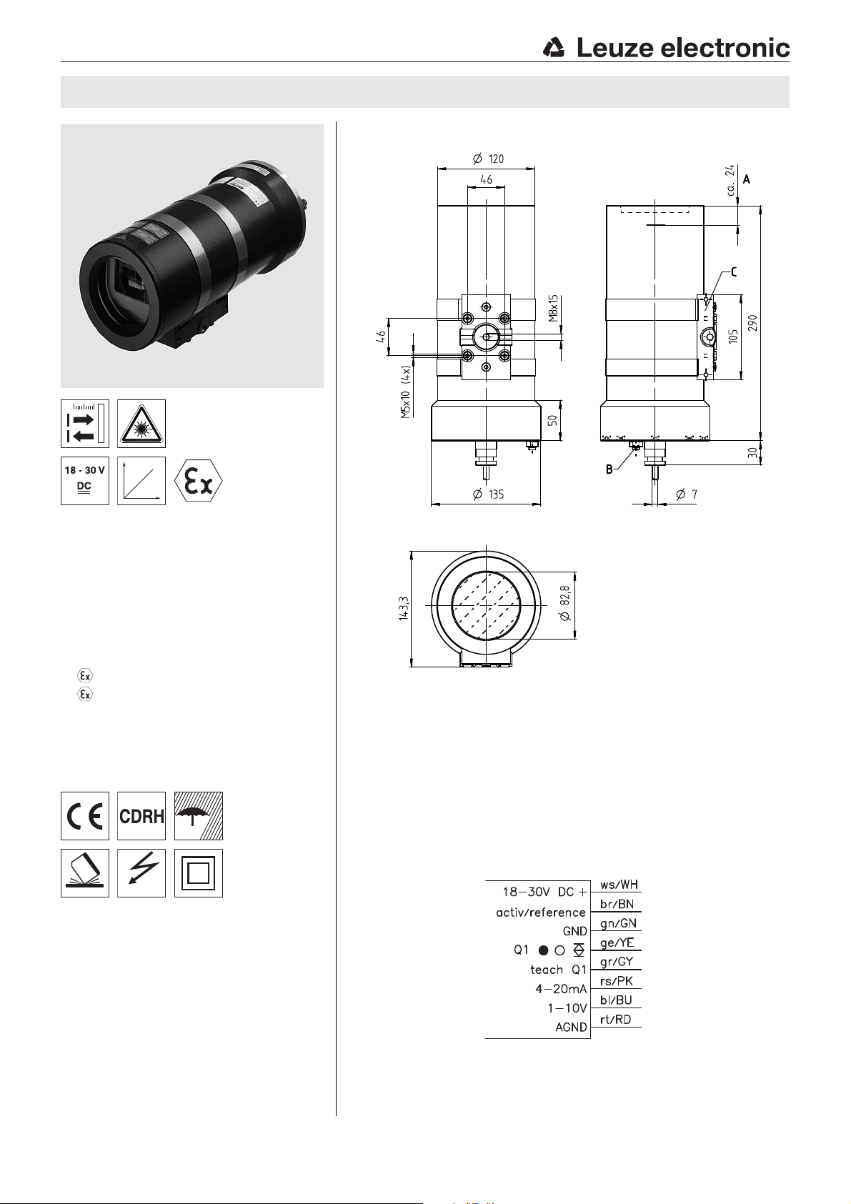
Dimensioned drawing
en 02-2013/10 50122342
0.2 … 30m
Reflection-independent distance
information
High accuracy through referencing
Analogue current and voltage output
1 teachable analogue and switching output
Configuration via LC display and key pad
(the sensor must be removed from the
Ex housing for this purpose)
EC type examination PTB 03 ATEX 1026
II 2G Ex d IIA T3
II 2D Ex td A21 IP 65 T80°C
Ex op is IIA T3 according to TÜV report
71386471
Cable 15m, 8-wire
Accessories:
(available separately)
Co-operative Target CTS 100x100
(reflectivity 50 … 90%)
A Reference level for the measurement (distance zero point)
B Earthing
C Mounting foot
Electrical connection
We reserve the right to make changes • DS_ODSL30V30MExd_en_50122342.fm
Leuze electronic GmbH + Co. KG In der Braike 1 D-73277 Owen Tel. +49 (0) 7021 573-0
info@leuze.com • www.leuze.com
ODSL 30/V-30M Ex d - 02
Page 2
ODSL 30 Ex
Specifications
Optical data
Measurement range
Resolution
Light source laser
Wavelength 650nm
Max. output power 4mW
Pulse duration 267ns
Light spot divergent, ∅ 6mm at 10m
2)
Error limits for current output, relative to measurement range end value
Absolute measurement accuracy
Repeatability
Systematic measurement error 6mm (owing to glass pane)
Temperature drift typ. 0.5mm/°C (without referencing)
Timing
Measurement time
Delay before start-up ≤ 1s
Electrical data
Operating voltage U
Residual ripple ≤ 15% of UB
Power consumption ≤ 4W
Switching output PNP transistor, HIGH active (default),
Signal voltage high/low ≥ (U
Analog output R
Indicators
Green LED continuous light ready
Yellow LED continuous light object inside teach-in measurement distance
Mechanical data
Housing metal
Optics cover glass
Weight approx. 6500g
Connection type cable 15m, 8-wire
Environmental data
Ambient temp. (operation/storage) -10°C … +45°C / -40 °C … +70 °C
Protective circuit
VDE safety class
Protection class IP 65
Laser class 2 (in accordance with EN 60825-1)
Standards applied IEC 60947-5-2
1) Temperature range 0°C … +45°C
2) Display and output resolution 0.1mm configurable
3) In temperature range from 0°C to +45°C, measurement object ≥ 50x50mm², with factory settings;
different error limits apply at temperatures < 0°C
4) Same object, identical environmental conditions
5) Configurable, depends on the reflectivity of the object and on the max. detection range
6) 2=polarity reversal protection, 3=short circuit protection for all outputs
7) Rating voltage 250 VAC
1)
1)
4)
5)
B
off no voltage
off object outside teach-in measurement distance
6)
7)
0.2 … 30m (18 … 90 % diffuse reflection)
0.2 … 20m (6 … 90 % diffuse reflection)
0.1mm/1mm (factory setting)
measurement range up to 2.5m:
± 2% without referencing, ± 1% with referencing
measurement range 2.5m up to 5m:
± 1.5% without referencing, ± 1% with referencing
measurement range 5m up to 30m:
± 1% without referencing, ± 1% with referencing
± 0.5% of measurement value
30 … 100ms (factory setting: 100ms)
18 … 30V DC (incl. residual ripple)
NPN transistor or push-pull through configuration
-2 V)/≤ 2V
B
≥ 2kΩ (voltage)
L
RL≤ 500Ω (current)
2, 3
II, all-insulated
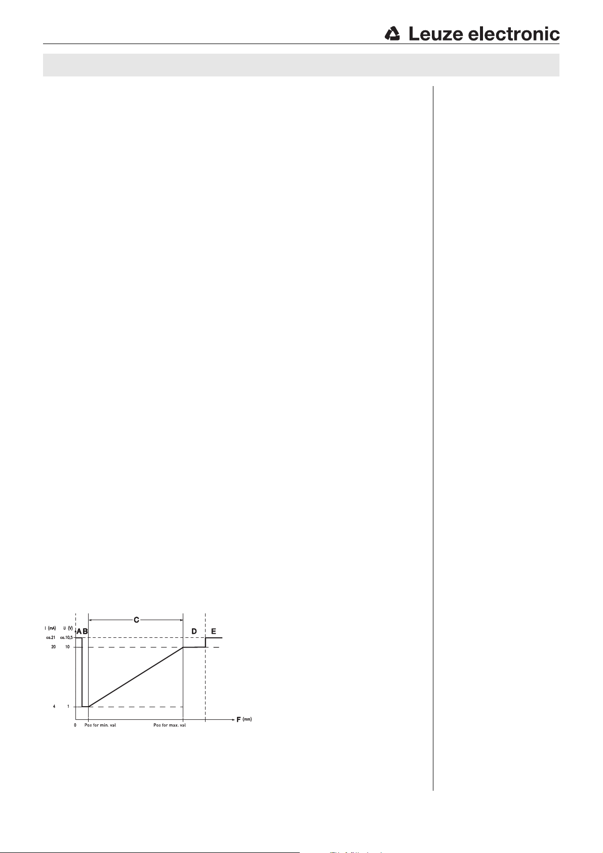
A Short range (no signal)
B Object present
C Measurement range
D Object present
E No object present (no signal)
F Measurement distance
3)
Remarks
Analog output:
The analog output is
factory-set to 200 to
5000mm with calibrated
current output. To adapt
the configuration, the
sensor must be removed
from the Ex housing.
Teaching procedure
(factory setting):
Position the measurement
object at the desired measurement distance. Apply
+U
to the teach input.
B
Take teach input back to
GND, switching output
has now been taught.
Edge on line teach Q1
teaches output Q1.
During the teaching of Q1,
yellow LED Q1 will flash.
Activation/referencing
input:
Referencing is carried out
by applying the voltage
(for a duration of about
300ms).
If this process is activated
before the measurement,
the highest possible accuracy is achieved.
Laser warning signs:
It is important to attach
the stick-on labels delivered with the device! If the
signs could be covered
due to the installation
location of the device,
attach them close to the
device so that it is not
possible to look into the
laser beam when reading
the notices.
Approved purpose:
This product may only be
used by qualified personnel and must only be used
for the approved purpose.
This sensor is not a safety
sensor and is not to be
used for the protection of
persons.
Order guide
Designation Part no.
with connection cable 15m, 8-wire ODSL 30/V-30M Ex d 50122319
ODSL 30/V-30M Ex d - 02 2013/10
Page 3

ODSL 30 Ex Optical laser distance sensors
Notices for the safe use of sensors in potentially explosive areas
Intended application range
The distance sensors of the ODSL 30 Ex d series, without making contact, detect objects which are located in or move through
the light beam and measure the distance to these objects.
Validity
The sensors have an encapsulated, pressure-proof housing and can be used in the following areas with these classifications:
Device group Device category Equipment protection level Zone
II 2G Gb Zone 1
II 2D Db Zone 21
Attention!
Check whether the equipment classification corresponds to the requirements of the application.
The devices are not suited for the protection of persons and may not be used for emergency shutdown purposes.
A safe operation is only possible if the equipment is used properly and for its intended purpose.
Electrical equipment may endanger humans and (where applicable) animal health, and may threaten the safety of
goods if used incorrectly or under unfavorable conditions in potentially explosive areas.
The applicable national regulations (e.g. EN 60079-14) for the configuration and installation of explosion-proof sys-
tems must be observed
Installation, Commissioning
Attention!
Electrical equipment may endanger humans and (where applicable) animal health, and may threaten the safety of
goods if used incorrectly and under unfavorable conditions in potentially explosive areas.
A safe operation in potentially explosive areas is only possible if the equipment is used properly and for its intended
purpose.
The distance sensors of type ODSL 30 Ex d must only be installed and maintained by trained electricians.
When installing the sensors in Ex zones 1 and 21, the connection cable must be connected in a connection space
with increased safety Ex e, or outside the Ex area.
The housing must be connected at the marked external connection unit to the protective conductor system.
The respective applicable national regulations for the installation of electrical equipment in potentially explosive
areas must be observed.
Maintenance
No changes may be made to the devices of type ODSL 30 Ex d for potentially explosive areas.
Repairs to the sensors may only be performed by persons trained for such work or by the manufacturer. Defective devices must
be replaced immediately.
The housing must not be opened while the power is on! After switching off power, wait at least 10min. before opening the hous-
ing.
Cyclical maintenance of the sensors is not necessary.
Depending on the environmental conditions, it may occasionally be necessary to clean the light-emission surfaces of the sensors.
This cleaning must only be performed by persons trained for performing this task. A soft, damp cloth should be used for this
purpose. Cleaning agents that contain solvents must not be used.
Chemical resistance
The sensors of type ODSL 30 Ex d demonstrate good resistance against many diluted acids and bases.
Exposure to organic solvents is possible only under certain circumstances and only for short periods of time.
Resistance to chemicals should be examined on a case by case basis.
Leuze electronic GmbH + Co. KG In der Braike 1 D-73277 Owen Tel. +49 (0) 7021 573-0 ODSL 30/V-30M Ex d - 02
info@leuze.com • www.leuze.com
Page 4

ODSL 30 Ex
ODSL 30/V-30M Ex d - 02 2013/10
 Loading...