

Page 1

ODSL 30
Optical distance sensors
en 02-2014/08 50106655-01
We reserve the right to
make technical changes
TECHNICAL DESCRIPTION / SOFTWARE DESCRIPTION
Page 2

© 2014
Leuze electronic GmbH + Co. KG
Leuze electronic ODSL 30
Page 3

Table of contents
1 General information ........................................................................................................... 4
1.1 Explanation of symbols ........................................................................................................ 4
1.2 Important terms .................................................................................................................... 4
1.3 Declaration of conformity ..................................................................................................... 5
2 Safety .................................................................................................................................. 6
2.1 Proper use ........................................................................................................................... 6
2.2 Foreseeable misuse............................................................................................................. 7
2.3 Competent persons.............................................................................................................. 7
2.4 Disclaimer ............................................................................................................................ 8
2.5 Laser safety notices ............................................................................................................. 8
3 Description ODSL 30 ....................................................................................................... 12
3.1 General description............................................................................................................ 12
3.2 Typical Areas of Application for the ODSL 30.................................................................... 13
3.2.1 Continuous distance measurement............................................................................................. 13
3.2.2 Positioning tasks..........................................................................................................................13
3.2.3 Collision protection ......................................................................................................................14
3.3 Mounting ............................................................................................................................ 15
3.4 ODSL 30 Variants ..............................................................................................................16
3.4.1 ODSL 30/V… with Analogue Output............................................................................................17
3.4.2 ODSL 30/24… with three switching outputs................................................................................20
3.4.3 ODSL 30/D… with Serial Output ................................................................................................. 21
3.5 Operation with fieldbus and Ethernet ................................................................................. 29
3.6 Operation ODSL 30 ........................................................................................................... 30
3.6.1 LED indicators ODSL 30..............................................................................................................30
3.6.2 Switching on ................................................................................................................................31
3.6.3 Adjustment of the display contrast...............................................................................................31
3.6.4 Reset to factory settings ..............................................................................................................31
3.6.5 Querying the device software version..........................................................................................32
3.6.6 Referencing the device................................................................................................................32
3.7 Configuration ODSL 30 ...................................................................................................... 33
3.7.1 Configuration / menu structure ODSL 30/V… (analogue) ........................................................... 34
3.7.2 Configuration / menu structure ODSL 30/24… (3 switching outputs)..........................................36
3.7.3 Configuration / menu structure ODSL 30/D 232… (digital RS 232).............................................39
3.7.4 Configuration / menu structure ODSL 30/D 485… (digital RS 485).............................................42
3.7.5 Operating example ......................................................................................................................45
3.8 Advanced Menu (for software versions V01.10 and newer) .............................................. 48
3.8.1 Setting an Offset/Preset Value - Compensating for Mounting Tolerances..................................48
3.8.2 Reduction in Measurement Time to as Little as 30ms ................................................................50
3.8.3 Changing the Display Resolution.................................................................................................51
Leuze electronic ODSL 30 1
Page 4

Table of contents
4 Technical Data ODSL 30.................................................................................................. 52
4.1 General specifications........................................................................................................ 52
4.2 Device-specific data........................................................................................................... 53
4.2.1 ODSL 30/V-30M-S12 ...................................................................................................................53
4.2.2 ODSL 30/24-30M-S12..................................................................................................................54
4.2.3 ODSL 30/D 232-30M-S12 ............................................................................................................55
4.2.4 ODSL 30/D 485-30M-S12 ............................................................................................................56
4.3 Dimensioned and connection drawings ............................................................................. 57
5 Type overview and accessories ..................................................................................... 60
5.1 Type overview.................................................................................................................... 60
5.2 Accessories........................................................................................................................ 61
6 Installation ........................................................................................................................ 62
6.1 Storage, transportation ......................................................................................................62
6.2 Mounting ............................................................................................................................ 62
6.3 Teach-in ............................................................................................................................. 63
7 Software............................................................................................................................ 65
7.1 Connecting to a PC............................................................................................................ 65
7.1.1 Connection of the ODSL 30 to a PC ............................................................................................65
7.2 Installation of the ODS 96 configuration software.............................................................. 66
7.3 Starting the program .......................................................................................................... 66
7.3.1 Description of the Menu Commands............................................................................................68
7.3.2 Trade shows.................................................................................................................................69
2 ODSL 30 Leuze electronic
Page 5

Figures and tables
Figure 2.1: Laser aperture, laser warning sign ............................................................................. 10
Figure 2.2: Laser warning and information signs – supplied stick-on labels ................................ 11
Figure 3.1: Application example Positioning of Elevating Platforms.............................................13
Figure 3.2: Application example "Collision Prevention" ................................................................ 14
Figure 3.3: ODSL 30 with BT 30................................................................................................... 15
Figure 3.4: Dimensioned drawing BT 30 ......................................................................................15
Figure 3.5: Characteristic output curve ODSL 30/V… with positive gradient ...............................17
Figure 3.6: Characteristic output curve ODSL 30/V… with negative gradient .............................. 17
Figure 3.7: Behaviour of the switching outputs ODSL 30/24… (PNP output active high) ............20
Figure 3.8: Serial transmission formats ODSL 30/D… ................................................................. 22
Figure 3.9: Voltage divider for the RS 485 bus termination .......................................................... 28
Figure 3.10: Indicator and operating elements ODSL 30 ...............................................................30
Figure 3.11: ODSL 30 measurement values with a uniqueness range of 9.8m ............................. 51
Figure 4.1: Dimensioned drawing ODSL 30 variants ................................................................... 57
Figure 4.2: Electrical Connection ODSL 30/V… ........................................................................... 58
Figure 4.3: Electrical Connection ODSL 30/24… .........................................................................58
Figure 4.4: Electrical Connection ODSL 30/D 232….................................................................... 58
Figure 4.5: Electrical Connection ODSL 30/D 485….................................................................... 59
Table 5.1: ODSL 30 type overview.............................................................................................. 60
Table 5.2: Accessories ODSL 30 ................................................................................................61
Figure 6.1: View through a chase.................................................................................................62
Figure 7.1: Connection of the ODSL 30 to a PC via the programming terminal UPG 5 ............... 65
Figure 7.2: Installation directory ................................................................................................... 66
Figure 7.3: Device selection .........................................................................................................67
Figure 7.4: Start menu before measurement................................................................................67
Figure 7.5: Display of the current measurement values of the ODSL 30 connected.................... 69
Leuze electronic ODSL 30 3
Page 6

General information
1 General information
1.1 Explanation of symbols
The symbols used in this technical description are explained below.
Attention
This symbol precedes text messages which must strictly be observed. Failure to comply with
this information results in injuries to personnel or damage to the equipment.
Attention Laser Radiation
This symbol warns of possible danger caused by hazardous laser radiation.
Notice
This symbol indicates text passages containing important information.
1.2 Important terms
Phase measurement
Distance measuring procedure, which determines the distance of an object by the
shift of the phase angle of the light reflected from the object.
Uniqueness range
Due to the periodicity of the sinusoid, the phasing of the signals received by the
ODSL 30 limits the determination of unique measurement values to within a specific
interval. The length of this interval is called the uniqueness range. A large uniqueness
range is equivalent to high background suppression (see chapter 3.8.2).
Absolute measurement accuracy
Shows the possible divergence of the measurement value from the anticipated value
through changes in the environmental conditions during the measuring process.
Higher accuracy is given at constant environmental conditions.
Repeatability
Measuring distance change with repeated measurement at the same output signal
(observe the same peripheral conditions as with resolution).
Resolution
The smallest possible distance change of the measurement object, which causes a
definite change in the output signal.
4 ODSL 30 Leuze electronic
Page 7

General information
U
L
US
C
LISTED
Referencing
Device function of the ODSL 30… for the compensation of a possible temperature
drift. A reference measurement should be carried out before each exact measurement. The reference measurement is activated via a separate device input and is
automatically carried out once after the device is switched on.
Diffuse reflection
Return and/or degree of reflection of the radiated light.
Measurement time
The measurement time is dependent on the selected uniqueness range and the luminosity coefficient of the object (see chapter 3.8.2).
Delay before start-up
The delay before start-up indicates the point in time when the first valid measurement
can be obtained after switching on.
Light switching/Dark switching
Specifies the behaviour of the switching output: light switching if an object is located
within the configured distance range, dark switching if an object is located outside of
the configured distance range.
Insensitivity towards ambient light
Indicates the insensitivity of the measurement result towards ambient light. The
ODSL 30 is reliably measuring even with extraneous light intensity of 5kLux. Typical
light intensity in a work place is only 1kLux.
1.3 Declaration of conformity
The optical distance sensors of the ODSL 30 series have been manufactured observing
current European standards and guidelines.
Notice
A corresponding Declaration of Conformity can be requested from the manufacturer.
The manufacturer of the product, Leuze electronic GmbH + Co. KG in D-73277 Owen,
possesses a certified quality assurance system in accordance with ISO 9001.
Leuze electronic ODSL 30 5
TNT 35/7-24V
Page 8

Safety
2 Safety
This sensor was developed, manufactured and tested in line with the applicable safety standards. It corresponds to the state of the art.
2.1 Proper use
Optical distance sensors of the ODSL 30 series are intelligent, configurable sensors for the
optical, contactless measurement of the distance to objects.
Areas of application
The optical distance sensors of the ODSL 30 series have been designed for the following
areas of application:
• distance measurement
• contour determination
• positioning of side-tracking skates, cranes, lifting devices
• filling level measurement
CAUTION
Observe intended use!
Only operate the device in accordance with its intended use.
The protection of personnel and the device cannot be guaranteed if the device is operated in a manner not complying with its intended use.
Leuze electronic GmbH + Co. KG is not liable for damages caused by improper use.
Read the technical description before commissioning the device.
Knowledge of this technical description is an element of proper use.
NOTE
Comply with conditions and regulations!
Observe the locally applicable legal regulations and the rules of the employer's liability
insurance association.
Attention
For UL applications, use is only permitted in class 2 circuits in accordance with the NEC
(National Electric Code).
6 ODSL 30 Leuze electronic
Page 9

2.2 Foreseeable misuse
Any use other than that defined under the "Approved purpose" or which goes beyond that
use is considered improper use.
In particular, use of the device is not permitted in the following cases:
• rooms with explosive atmospheres
• in circuits which are relevant to safety
• operation for medical purposes
NOTE
Do not modify or otherwise interfere with the device.
Do not carry out modifications or otherwise interfere with the device.
The device must not be tampered with and must not be changed in any way.
The device must not be opened. There are no user-serviceable parts inside.
Repairs must only be performed by Leuze electronic GmbH + Co. KG.
2.3 Competent persons
Connection, mounting, commissioning and adjustment of the device must only be carried
out by competent persons.
Prerequisites for competent persons:
• They have a suitable technical education.
• They are familiar with the rules and regulations for occupational safety and safety at
work.
• They are familiar with the technical description of the device.
• They have been instructed by the responsible person on the mounting and operation
of the device.
Safety
Certified electricians
Electrical work must be carried out by a certified electrician.
Due to their technical training, knowledge and experience as well as their familiarity with
relevant standards and regulations, certified electricians are able to perform work on electrical systems and independently detect possible hazards.
In Germany, certified electricians must fulfill the requirements of accident-prevention regulations BGV A3 (e.g. electrician foreman). In other countries, there are respective regulations that must be observed.
Leuze electronic ODSL 30 7
TNT 35/7-24V
Page 10

Safety
2.4 Disclaimer
Leuze electronic GmbH + Co. KG is not liable in the following cases:
• The device is not being used properly.
• Reasonably foreseeable misuse is not taken into account.
• Mounting and electrical connection are not properly performed.
• Changes (e.g., constructional) are made to the device.
2.5 Laser safety notices
ATTENTION, LASER RADIATION – LASER CLASS 2
Never look directly into the beam!
The device fulfills the EN 60825-1:2008-05 (IEC 60825-1:2007) safety regulations for a
product in laser class 2 as well as the U.S. 21 CFR 1040.10 regulations with deviations
corresponding to "Laser Notice No. 50" from June 24th, 2007.
Never look directly into the laser beam or in the direction of reflecting laser beams!
If you look into the beam path over a longer time period, there is a risk of injury to the
retina.
Do not point the laser beam of the device at persons!
Intercept the laser beam with an opaque, non-reflective object if the laser beam is
accidentally directed towards a person.
When mounting and aligning the device, avoid reflections of the laser beam off reflec-
tive surfaces!
CAUTION! The use of operating or adjusting devices other than those specified here
or carrying out of differing procedures may lead to dangerous exposure to radiation.
The use of optical instruments or devices (e.g., magnifying glasses, binoculars) with
the product will increase eye hazard.
Adhere to the applicable legal and local regulations regarding protection from laser
beams acc. to EN 60825 (IEC 60825) in its latest version.
The device must not be tampered with and must not be changed in any way.
There are no user-serviceable parts inside the device.
Repairs must only be performed by Leuze electronic GmbH + Co. KG.
8 ODSL 30 Leuze electronic
Page 11

Safety
NOTE
Affix laser information and warning signs!
Laser information and warning signs are attached to the device (see figure 2.1). Also
included with the device are self-adhesive laser warning and laser information signs (stickon labels) in multiple languages (see figure 2.2).
Affix the laser information sheet with the language appropriate for the place of use to
the device.
When using the device in the US, use the stick-on label with the "Complies with
21 CFR 1040.10" notice.
Affix the laser information and warning signs near the device if no signs are attached
to the device (e.g. because the device is too small) or if the attached laser information
and warning signs are concealed due to the installation position.
Affix the laser information and warning signs so that they are legible without exposing
the reader to the laser radiation of the device or other optical radiation.
Leuze electronic ODSL 30 9
TNT 35/7-24V
Page 12

Safety
A Laser exit opening
B Laser warning sign
A
B
Figure 2.1: Laser aperture, laser warning sign
10 ODSL 30 Leuze electronic
Page 13

AVOID EXPOSURE – LASER RADIATION
IS EMITTED FROM THIS APERTURE
EXPOSITION DANGEREUSE – UN RAYONNEMENT
LASER EST ÉMIS PAR CETTE OUVERTURE
LASERSTRAHLUNG
NICHT IN DEN STRAHL BLICKEN
LASER KLASSE 2
DIN EN 60825-1:2008-05
Max. Leistung (peak):
Impulsdauer:
Wellenlänge:
RADIAZIONE LASER
NON FISSARE IL FASCIO
APARRECCHIO LASER DI CLASSE 2
EN 60825-1:2007
Potenza max. (peak):
Durata dell'impulso:
Lunghezza d'onda:
LASER RADIATION
DO NOT STARE INTO BEAM
CLASS 2 LASER PRODUCT
EN 60825-1:2007
Maximum Output (peak):
Pulse duration:
Wavelength:
RAYONNEMENT LASER
NE PAS REGARDER DANS LE FAISCEAU
APPAREIL À LASER DE CLASSE 2
EN 60825-1:2007
Puissance max. (crête):
Durée d`impulsion:
Longueur d`onde:
RADIACIÓN LÁSER
NO MIRAR FIJAMENTE AL HAZ
PRODUCTO LÁSER DE CLASE 2
EN 60825-1:2007
Potencia máx. (peak):
Duración del impulso:
Longitud de onda:
RADIAÇÃO LASER
NÃO OLHAR FIXAMENTE O FEIXE
EQUIPAMENTO LASER CLASSE 2
EN 60825-1:2007
Potência máx. (peak):
Período de pulso:
Comprimento de onda:
LASER RADIATION
DO NOT STARE INTO BEAM
CLASS 2 LASER PRODUCT
EN 60825-1:2007
Complies with 21 CFR 1040.10
Maximum Output (peak):
Pulse duration:
Wavelength:
䉏⏘戟⺓
▎䦃展⏘㧮
伊䉏⏘ℶ❐
GB7247.1-2012
㦏⮶戢⒉᧤⽿⋋᧥
厘⑁㖐兼㢅梃
㽱栎
4,5 mW
267 ns
655 nm
4,5 mW
267 ns
655 nm
4.5 mW
267 ns
655 nm
4,5 mW
267
n
s
655 nm
4,5 mW
267 ns
655 nm
4,5 mW
267 ns
655 nm
4.5 mW
267 ns
655 nm
4.5 mW
267 ns
655 nm
50101929-02
Safety
Figure 2.2: Laser warning and information signs – supplied stick-on labels
TNT 35/7-24V
Leuze electronic ODSL 30 11
Page 14

Description ODSL 30
3 Description ODSL 30
3.1 General description
The ODSL 30 is a lase distance sensor with an extensive area of application. The equipment
is available in different versions with analogue outputs, digital outputs, or switching outputs.
The distance measurement uses the phase measurement principle. The measurement
range lies between 0.2 … 30m.
Integrated in the device are a keypad and a two-line LC display which can be used to
configure the ODSL 30. During measurement operation, the display shows the current
measurement value. The switching point of the switching outputs can easily be set via a
teach input on all variants.
Remarks
Moving objects into the measurement beam from the side may lead to incorrect measurement values.
By carrying out the integrated reference measurement function before a measurement, the
sensor's accuracy can be improved. To achieve this, the active input (Pin 2) can be configured via the menu to act either as an activation input with referencing, or as a pure referencing input. While the referencing function is carried out (duration about 0.3s), no
measurement can be taken.
If the device is used in areas subject to electrostatic charges, it is recommended to connect
the housing of the ODSL 30 to a common potential.
1)
Accessories
The ODSL 30 ships with the mounting device BT 30 for easy mounting and alignment
(further accessories see chapter 5.2).
1) Luminosity coefficient 6 … 90% throughout the entire temperature range, measurement object
50 x 50mm
ODSL 30/D…Measurement range up to 65m, luminosity coefficient 50 … 90%
2
.
12 ODSL 30 Leuze electronic
Page 15

3.2 Typical Areas of Application for the ODSL 30
3.2.1 Continuous distance measurement
All ODSL 30 variants with analogue/digital or switching output can be used for continuous
distance measuring. The menu-guided configuration via keypad and LC display on the
device without additional software permits the adaptation to a large number of applications.
Depending on position or settings of the ODSL 30, various applications are possible:
• Positioning of side-tracking skates, cranes, lifting devices
• Contour determination through controlled passing movement of an object through the
beam of the ODSL 30.
• Volume measuring by taking measurements on two levels during the concurrent
movement of the object.
• Determination of the diameter, e.g., on paper rolls.
• Measuring the thickness of planks with two opposing sensors and a differential of the
two measured values.
3.2.2 Positioning tasks
The ODSL 30 variants with analogue output and/or up to three teachable switching outputs
are ideally suited for basic positioning tasks, such as the height/level adjustment of elevating
platforms and rising floors.
The ODSL 30 is mounted in a way to enable positioning in the direction of the measuring
beam.
Description ODSL 30
Figure 3.1: Application example Positioning of Elevating Platforms
Leuze electronic ODSL 30 13
TNT 35/7-24V
Page 16

Description ODSL 30
PON Q1 Q2 Q3
Leuze electronic
ENTER
PON Q1 Q2 Q3
Leuze electronic
ENTER
PON Q1 Q2 Q3
Leuze electronic
ENTER
3.2.3 Collision protection
The ODSL 30 is ideally suited to be used as collision prevention device:
• Distance regulation via the analogue output of the ODSL 30
• Collision prevention via the switching outputs of the ODSL 30
Figure 3.2: Application example "Collision Prevention"
14 ODSL 30 Leuze electronic
Page 17

3.3 Mounting
The ODSL 30 ships with the mounting device BT 30 that permits the easy mounting and
alignment of the ODSL 30.
Figure 3.3: ODSL 30 with BT 30
Dimensioned drawing BT 30
Description ODSL 30
Figure 3.4: Dimensioned drawing BT 30
Leuze electronic ODSL 30 15
TNT 35/7-24V
Page 18

Description ODSL 30
Notice
With the help of the two aiming notches on the upper side of the device, you can carry out a
coarse alignment of the ODSL 30 even before commissioning.
3.4 ODSL 30 Variants
Model variations
The ODSL 30 is available in four variants:
•as a laser distance sensor with 2 analogue outputs 1 … 10 V and 4 … 20 mA
and 1 universally configurable switching output
measurement range between 0.2 … 30m
•as a laser distance sensor with 3 universally configurable switching outputs
measurement range between 0.2 … 30m
•as a laser distance sensor with serial interface RS 232
and 2 universally configurable switching outputs,
measurement range between 0.2 … 30m
•as a laser distance sensor with serial interface RS 485/RS 422
and 2 universally configurable switching outputs,
measurement range between 0.2 … 30m
16 ODSL 30 Leuze electronic
Page 19

3.4.1 ODSL 30/V… with Analogue Output
Object present
Object present
Measurement range
Measurement
distance [mm]
0 Distance for min. analog value Distance for max. analog value
U [V]
typ. 10.5
10
1
I [mA]
typ. 21
20
4
No object
present
(no signal)
Ascending characteristic output curve
Short range (no signal)
Object present
Object present
Measurement range
Measurement
distance [mm]
0 Distance for max. analog value Distance for min. analog value
U [V]
10
1
typ. 0.5
I [mA]
20
4
typ. 3
No object
present
(no signal)
Descending characteristic output curve
Short range (no signal)
Analogue Output ODSL 30/V…
Figure 3.5: Characteristic output curve ODSL 30/V… with positive gradient
Description ODSL 30
Figure 3.6: Characteristic output curve ODSL 30/V… with negative gradient
Leuze electronic ODSL 30 17
TNT 35/7-24V
Page 20

Description ODSL 30
Behaviour of the analogue outputs of the ODSL 30/V…
The ODSL 30/V… has an analogue output with linear behaviour. A current output
(4 … 20mA) and a voltage output (1 … 10V) are available to the user. In order to achieve
the highest resolution possible, the range of the analog output should be set as small as the
application allows. The analogue output can be adjusted within the measurement range by
configuration via the keypad and LC display (adaptation of the characteristic output curve).
The parameter
out for the current or voltage output. The characteristic output curve can be configured with
a positive or negative gradient. For this purpose, the two distance values
Pos for min. val and Pos for max. val for the minimum and maximum
analogue output value are set accordingly in the range between 200 mm and 30,000 mm
(see figure 3.5 and figure 3.6).
Cal. Ana. Output determines whether the calibration is to be carried
Current output
Object distance
no object or object too close or too far
away (no signal)
= distance for minimum analogue value 4mA 20mA 1V 10V
= distance for maximum analogue value 20mA 4mA 10V 1V
< distance for minimum analogue value 4mA 20mA 1V 10V
> distance for maximum analogue value 20mA 4mA 10V 1V
1) The typical values only apply if the current output is calibrated.
2) The typical values only apply if the voltage output is calibrated.
with positive
gradient
>20.5mA
(typ. 21mA)
1)
with negative
gradient
<3.5mA
(typ. 3mA)
Voltage output
with positive
gradient
>10.25V
(typ. 10.5V)
2)
with negative
gradient
<0.75V
(typ. 0.5V)
Teach-in of the characteristic output curve
In addition to the edge-controlled teach-in (slope control) of the switching outputs, teachin of the characteristic output curve is also possible via a teach line for devices with software
version V01.10 and newer (see chapter 3.6.5). The following steps are required for the line
teach-in of the analogue characteristic curve:
1. Activation of the analogue line teach function via the keypad and menu.
Activate Input Menu -> Teach Mode -> Teach Mode time control.
2. Position measurement object at the desired measurement distance.
3. The respective teach function is activated by applying the active level (default +U
the teach input "Teach Q1" (pin 5). The teach event is indicated by the flashing of the
) to
B
LEDs and on the display.
Teach function Duration of teach
signal
Upper switching point
switching output Q1
Distance value for
analogue output 1V / 4mA
Distance value for
analogue output 10V / 20mA
2 … 4s flash synchronously
4…6s
6 … 8s flashing
Green LED Yellow
LED
continuous
light
flashing
continuous
light
18 ODSL 30 Leuze electronic
Page 21
Description ODSL 30
4. To finish the teach event, disconnect the teach input from the teach signal after the
desired time.
5. A successful teach event is signaled by the end of the flashing of the LEDs. The menu
entries can be used to check that the teach values are properly accepted and to make
any changes.
Error messages
Rapid flashing of the green LED following a teach event indicates an unsuccessful teach
event. The sensor remains ready for operation and continues to function with the old values.
Remedy:
• Repeat teach event or
• Activate teach input for more than 8s or
• Disconnect sensor from voltage to restore the old values.
Behaviour of the switching output of the ODSL 30/V…
Additionally, a switching output with two switching points (switching window) is available with
the ODSL 30/V… with analogue output. The upper switching point can be taught using a
teach line. By configuring within the measurement range, it is possible to set the lower and
upper switching points, the switching hysteresis, the switching behavior (light/dark
switching), and the type of switching output (PNP high active or NPN low active or PNP/NPN
push-pull).
Teaching always takes place towards the upper switching point (see figure 3.7 on page 20).
The lower switching point is set to the value '199' by default and can be adjusted via the
operating menu. The following table applies for a lower switching point of 199mm.
Object distance
No object (no signal) off on
< teach value on off
> teach value off on
1) Only if a received signal is available that can still be evaluated, otherwise same as "no
<200mm
object"
1)
Light switching Dark switching
output Q1 output Q1
on off
Leuze electronic ODSL 30 19
TNT 35/7-24V
Page 22

Description ODSL 30
Hysteresis
Measurement
distance
ON
OFF
Lower
switching point
Upper
Switching point
(Teach-In)
Hysteresis
ON
OFF
Output PNP active high
Light switching
Dark switching
3.4.2 ODSL 30/24… with three switching outputs
Switching outputs ODSL 30/24…
Figure 3.7: Behaviour of the switching outputs ODSL 30/24… (PNP output active high)
Behaviour of the switching outputs of the ODSL 30/24…
The ODSL 30/24… is equipped with three independent switching outputs, each with 2
switching points (switching windows). The upper switching points can be taught using a
teach line. By configuring within the measurement range, it is possible to set the lower and
upper switching points, the switching hysteresis, the switching behavior (light/dark
switching), and the type of switching output (PNP high active or NPN low active or PNP/NPN
push-pull).
Teaching always takes place towards the upper switching point (see figure 3.7). Each of the
lower switching points is set to the value '199' by default and can be adjusted via the operating menu. The following table applies for a lower switching point of 199mm.
Object distance
No object (no signal) off off off On On On
< teach value On On On off off off
> teach value off off off On On On
1) Only if a received signal is available that can still be evaluated, otherwise same as "no
< 200mm
1)
object"
20 ODSL 30 Leuze electronic
output Q1 output Q2 output Q3 output Q1 output Q2 output Q3
Light switching Dark switching
On On On off off off
Page 23

3.4.3 ODSL 30/D… with Serial Output
Transmission formats
The ODSL 30/D… has 2 digital switching outputs and one serial interface which is implemented either as an RS 232 interface or as an RS 485/RS 422 interface. The transmission
rate can be set to between 600 and 115200 baud.
The serial transmission is carried out with 1 start bit, 8 data bits and 1 or 2 stop bits without
parity.
For the transmission of the measurement values, 6 different transmission modes may be
configured (see figure 3.8):
• ASCII measurement value (6 bytes, measurement range 0 … 65m,
• ASCII measurement value 0.1 mm (7 bytes, measurement range 0 … 65m,
• 14 bit measurement value (2 bytes, measurement range 0 … 16m,
• 16 bit measurement value (3 bytes, measurement range 0 … 65m,
• 20 bit measurement value (4 bytes, measurement range 0 … 65m,
• Remote Control Operation
(Remote Control)
2)
The output format is activated by configuration with the keypad and menu.
Notice!
Selecting an output resolution of 0.1 mm does not change the internal measurement system
of the ODSL 30 and does not increase its accuracy. For this reason, measurement values
with a resolution of 0.1mm may vary in successive measurements depending on the application.
resolution 1mm)
1)
resolution 0.1mm)
resolution 1mm)
resolution 1mm)
resolution 0.1mm)
Description ODSL 30
1)
1)
1)
1)
1) Continuous measured value output in a 100ms grid. For the ODSL 30/D 485…, the transfer is
carried out in RS 422 mode, i.e., with permanent transmission on the Tx+ and Tx- lines.
2) For the ODSL 30/D 485…, the transfer is carried out in RS 485 mode, i.e., the Tx+ and Txlines are switched to receive. This permits several ODSL 30/D 485… to be connected onto a
single bus. In this case, the device addresses of the individual devices must differ from each
other.
The ODSL 30/D 232… can also be operated via remote control, however, only as a point-topoint-connection between the ODSL 30 and the controller.
Leuze electronic ODSL 30 21
TNT 35/7-24V
Page 24

Description ODSL 30
707070
00 01
xx 1 0
7070
0
1
Measurement value = 16 bits (measurement range 0 … 30m, resolution 1 mm)
1. Low Byte (bit 0 = 0, bit 1 = 0)
Measurement value = 14 bits (measurement range 0 … 15m, resolution 1 mm)
Measurement value ASCII transmission
Transmission format: MMMMM<CR>
MMMMM = 5-digit measurement value
<CR> = ASCII character "Carriage Return" (x0D)
bit 5
bit 4
bit 3
bit 2
bit 1
bit 0 (LSB)
bit 11
bit 10
bit 9
bit 8
bit 7
bit 6
don’t care
don’t care
bit 15 (MSB)
bit 14
bit 13
bit 12
2. Middle Byte (bit 0 = 1, bit 1 = 0) 3. High Byte (bit 0 = 0, bit 1 = 1)
1. Low Byte (bit 0 = 0) 2. High Byte (bit 0 = 1)
bit 6
bit 5
bit 4
bit 3
bit 2
bit 1
bit 0 (LSB)
bit 13 (MSB)
bit 12
bit 11
bit 10
bit 9
bit 8
bit 7
Remote control operation
ASCII transfer of the measurement value on request
4 digits (4 bytes), 5 digits (5 bytes) or 6 digits (6 bytes).
Measurement value ASCII transmission, resolution 0.1mm
Transmission format: MMMMMM<CR>
MMMMMM = 6-digit measurement value in tenths of a mm without decimal point
<CR> = ASCII character "Carriage Return" (x0D)
70
0
0
70
0 1
70
1 0
70
xxxx 1 1
Measurement value = 20bits (measurement range 0 … 30 m, resolution 0.1 mm)
1. Low Byte
(bit 0 = 0, bit 1 = 0)
bit 5
bit 4
bit 3
bit 2
bit 1
bit 0 (LSB)
bit 11
bit 10
bit 9
bit 8
bit 7
bit 6
bit 17
bit 16
bit 15
bit 14
bit 13
bit 12
don’t care
don’t care
don’t care
don’t care
bit 19 (MSB)
bit 18
bit 19 (MSB)
2. Middle Low Byte
(bit 0 = 1, bit 1 = 0)
3. Middle High Byte
(bit 0 = 0, bit 1 = 1)
4. High Byte
(bit 0 = 1, bit 1 = 1)
Figure 3.8: Serial transmission formats ODSL 30/D…
22 ODSL 30 Leuze electronic
Page 25

Description ODSL 30
Measurement value output for various transmission types
Measurement value output for transmission type
Object distance
No object (no signal) 65535 655350 16383 65535 655350 9999 65535 655350
1)
<200mm
200mm … 9900mm
9901mm … 16000mm
16001mm … 65000mm
> 65000mm 65001 650010 16001 65001 650010 9901 65001 650010
Object distance + Offset
> 65000mm
(Offset Direction neg.)
Object distance - Offset
<0mm
(Offset Direction pos.)
Device error 00000000
1) Only if a received signal is available that can still be evaluated, otherwise same as "no object"
ASCII
5 bytes
Distance
value
in mm
Distance
value
in mm
Distance
value
in mm
Distance
value
in mm
65001 650010 16001 65001 650010 9901 65001 650010
ASCII
6 bytes
Distance
value
in 1/10mm
Distance
value
in 1/10mm
Distance
value
in 1/10mm
Distance
value
in 1/10mm
00000000
14 bit 16 bit 20 bit Remote
Distance
value
in mm
Distance
value
in mm
Distance
value
in mm
16001
Distance
value
in mm
Distance
value
in mm
Distance
value
in mm
Distance
value
in mm
Distance
value
in 1/10mm
Distance
value
in 1/10mm
Distance
value
in 1/10mm
Distance
value
in 1/10mm
4 bytes
Distance
value
in mm
Distance
value
in mm
9901
9901
Remote
5 bytes
Distance
value
in mm
Distance
value
in mm
Distance
value
in mm
Distance
value
in mm
Remote
6 bytes
Distance
value
in 1/10mm
Distance
value
in 1/10mm
Distance
value
in 1/10mm
Distance
value
in 1/10mm
Commands for remote control operation
For remote control operation (parameter Remote Control), a device address between
0 … 14 can be set. In this operating mode, the ODSL 30/D… reacts only to commands from
the controller.
With asynchronous measurement, the sensor measures continuously. After processing
the command, the next measurement value of the ODSL 30 is transmitted. The response
time of the ODSL 30 varies within the scope of the measurement time and is dependent on
the time of the query and the state of the internal measurement cycle of the ODSL 30 at this
time.
With synchronous measurement, the measurement starts with processing of the current
command. The response time of the ODSL 30 is constant and is dependent only on the
configured measurement time.
The following control commands are available:
Leuze electronic ODSL 30 23
TNT 35/7-24V
Page 26

Description ODSL 30
Commands for the asynchronous measurement
Measurement value query, 4 digits:
012345678
Command
Sensor
response
Asynchronous measurement value query 5 digits, resolution 1 mm:
Command
Sensor
response
Asynchronous measurement value query 6 digits, resolution 0.1 mm:
Command
Sensor
response
Sensor
address
0x00
through
0x0E
"
"
*
(0x2A)
012345678
"
"
*
(0x2A)
"
"
*
(0x2A)
0123456789
"
"
*
(0x2A)
"
"
*
(0x2A)
Byte no. Response
––––––––
ASCII address ASCII distance measurement value
tens ones 1'000's 100's tens ones
Byte no. Response
ASCII
address
"0…9",
"A…D"
ASCII
address
"0…9",
"A…D"
ASCII
address
"0…9",
"A…D"
ASCII
address
"0…9",
"A…D"
"M"
(0x4D)
10'000's 1'000's 100's tens ones
"m"
(0x73)
10'000's 1'000's 100's tens ones tenths
"#"
(0x23)
ASCII distance measurement value
"#"
(0x23)
ASCII distance measurement value
–––––
Byte no. Response
––––––
"#"
(0x23)
State
State
"#"
(0x23)
(0x23)
–
"#"
time
max.
120ms
time
max.
120ms
time
max.
120ms
Commands for the synchronous measurement
The two following synchronous measurement commands "S" (5-digit measurement value,
resolution 1mm) or "s" (6-digit measurement value, resolution 0.1mm) enable the start of a
measurement at a precise time.
If a synchronous measurement value is requested via remote control operation:
• this command immediately switches on the laser and triggers the measurement.
• following the measurement cycle, the laser is switched off.
• the measured value is transmitted following this measurement cycle.
Notice!
Prerequisite for the function of the synchronous measurement value query is that the sensor
be deactivated (laser off)!
24 ODSL 30 Leuze electronic
Page 27

Description ODSL 30
For this purpose:
• the active/reference input (pin 2) must be connected to the inactive state (default: 0V)
or it must be open.
• the active/reference input (pin 2) must be configured as an activation and referencing
input:
Input Menu -> Input activ/ref -> input activ/ref Activation + Ref
Synchronous measurement value query 5 digits, resolution 1 mm:
Command
Sensor
response
Byte no. Response
0123456789
ASCII
"
*
(0x2A)
"
*
(0x2A)
address
"
"0…9",
"A…D"
address
"
"0…9",
"A…D"
"S"
"#"
(0x53)
(0x23)
ASCII
ASCII distance measurement value
10'000's 1'000's 100's tens ones
––––––
State
"#"
(0x23)
–
time
30
…
100ms
1)
Synchronous measurement value query 6 digits, resolution 0.1 mm:
Byte no. Response
0123456789
Command
Sensor
response
1) Depending on the configuration of the measurement time, see chapter 3.8 "Advanced
Menu (for software versions V01.10 and newer)", duration of data transmission not
included.
"
*
(0x2A)
"
*
(0x2A)
ASCII
address
"
"0…9",
"A…D"
address
"
"0…9",
"A…D"
"s"
"#"
(0x73)
(0x23)
ASCII
10'000's 1'000's 100's tens ones t enths
––––––
ASCII distance measurement value
State
"#"
(0x23)
time
30
…
100ms
1)
Notice!
To make the laser beam visible for adjustment purposes and to view measurement values
on the display, the
• active/reference input (pin 2) can be connected to the active state (default: 24 V) or
• the sensor can be activated with the command "A" (see page 26) or
• the active/reference input (pin 2) can be temporarily configured via the menu as a reference input:
Input Menu -> Input activ/ref -> Input activ/ref Referencing
TNT 35/7-24V
Possible errors and their causes
Instead of a synchronous measurement, an asynchronous measurement is performed.
Possible causes of the error: the synchronous measurement command was set by the activated, i.e. the measuring, sensor. Instead of the synchronous measurement, an asynchronous measurement was performed (corresponds to the commands "M" and "m").
Leuze electronic ODSL 30 25
Page 28
Description ODSL 30
Further commands
Activate referencing:
012345678
Command
Sensor
response
Activate sensor
Command
Sensor
response
Deactivate sensor
Command
Sensor
response
"
"
*
(0x2A)
"
"
*
(0x2A)
012345678
"
"
*
(0x2A)
"
"
*
(0x2A)
012345678
"
"
*
(0x2A)
"
"
*
(0x2A)
ASCII
address
"0…9",
"A…D"
ASCII
address
"0…9",
"A…D"
1)
:
ASCII
address
"0…9",
"A…D"
ASCII
address
"0…9",
"A…D"
1)
ASCII
address
"0…9",
"A…D"
ASCII
address
"0…9",
"A…D"
"R"
(0x52)
State
"A"
(0x41)
State
Byte no. Response
"#"
(0x23)
"#"
(0x23)
"#"
(0x23)
"#"
(0x23)
–––––
–––––350ms
Byte no. Response
–––––
–––––
time
time
max.
120ms
:
"D"
(0x44)
State
Byte no. Response
"#"
(0x23)
"#"
(0x23)
–––––
–––––
time
max.
120ms
Status byte (bitwise processing):
Bit number Value Meaning
7 (MSB) 0x80
6 0x40
5 0x20
4 0x10
3 0x08
2 0x04
1 0x02
0 (LSB) 0x01
1) The sensor is activated by default and in this case cannot be deactivated via the control command. The control command is only effective if the input activ/ref is configured as an activation
and referencing input. In this case, the following applies: The sensor is activated if the input
activ/ref is at active level or if the sensor is activated via control command. The sensor is deactivated if the input activ/ref is not at active level and the sensor is deactivated via control command.
always = 0 (reserved)
1 = other error, 0 = OK
always = 1, if the status is 0x20, the sensor functions flawlessly
always = 0 (reserved)
always = 0 (reserved)
1 = sensor deactivated, 0 = sensor activated
1 = no signal or signal too low, 0 = signal OK
1 = laser defective, 0 = Laser OK
26 ODSL 30 Leuze electronic
Page 29
Description ODSL 30
Behaviour of the switching outputs of the ODSL 30/D…
In addition, the ODSL 30/D… with serial output also has two switching outputs. The position
within the measuring range at which the switching outputs become active can be set arbitrarily via a teach line or via configuration. In addition to the switching points, it is also
possible to configure the switching hysteresis, the switching behaviour (light/dark switching),
and the type of switching output (PNP high active or NPN low active or PNP/NPN push-pull).
Teaching always takes place towards the upper switching point (see figure 3.7 on page 20).
The lower switching point is set to the value '199' by default and can be adjusted via the
operating menu. The following table applies for a lower switching point of 199mm.
Object distance
No object (no signal) off off on on
< teach value on on off off
> teach value off off on on
1) Only if a received signal is available that can still be evaluated, otherwise same as "no
<200mm
object"
1)
Light switching Dark switching
output Q1 output Q2 output Q1 output Q2
on on off off
Notes regarding the termination of the data lines of the ODSL 30/D 485…
The ODSL 30/D 485… features a combined transmitter and receiver component that can
transmit serial data according to the RS 485 and RS 422 standard (see TIA/EIA-485-A or
DIN66259, Part 3).
These standards define some basic rules that should be followed in order to achieve the
most reliable data transmission:
• The data lines A and B (which correspond to the ODSL 30 pins Tx+ and Tx-) are connected to an intrinsic impedance of Z
120 via a 2-wire twisted pair cable.
0
• The end of the data line (and the beginning in case of RS 485) is terminated using a
120 resistor. The ODSL 30/D 485… does not have an internal bus termination.
• The RS 485 bus participants are wired in an in-line bus topology, i.e., the data line is
fed from one bus participant to the next. Cable stubs are to be avoided or to be kept
as short as possible.
• The RS 485 specification assumes an inactive potential difference of U
200mV
AB
between the data lines. A bus termination in the form of a voltage divider should be
implemented in order to maintain this level. Usually, it is connected to the RS 485
coupling module of the PLC.
The RS 485 specification permits transmission rates in the megabit range for up to
32 participants. The ODSL 30/D 485… is designed for a data transmission rate of typically
9600 Baud (600 … 115200 Baud may be configured). In practice, this means that the strict
requirements regarding the bus termination and the cabling are "softened" for a few bus
participants.
TNT 35/7-24V
Leuze electronic ODSL 30 27
Page 30

Description ODSL 30
+24 V
15 kΩ
470 Ω
1,5 kΩ
A (Tx+)
B (Tx-)
However, it is important to maintain the bus idle levels (UAB 200mV). If the PLC coupling
module does not include a bus termination with voltage divider, the following circuit may be
used.
Figure 3.9: Voltage divider for the RS 485 bus termination
The RS 422 connection does not require a bus termination for cable lengths up to about
20m and data transmission rates less than 9600 Baud.
Further information:
• RS 422: Electrical Specification acc. to DIN 66259, Part 3
• ISO 8482: Abstract
Specifies the physical medium characteristics for twisted pair multipoint interconnections in either 2-wire or 4-wire network topology, a binary and bi-directional signal
transfer, the electrical and mechanical design of the endpoint system branch cables
and the common trunk cable which may be up to 1200m in length, the component
measurements of the integrated type generators and receivers within the endpoint
system, the applicable data signaling rate up to 12.5Mbit/s.
28 ODSL 30 Leuze electronic
Page 31

3.5 Operation with fieldbus and Ethernet
Sensors ODSL 30/D232-30M-S12 with an RS 232 serial interface can be connected with
MA 2xxi modular interfacing units to the following fieldbus and Ethernet types:
•PROFIBUSDP –> MA 204i
• Ethernet TCP/IP –> MA 208i
• CANopen –> MA 235i
• EtherCAT –> MA 238i
•PROFINET-IO –> MA 248i
• DeviceNet –> MA 255i
• EtherNet/IP –> MA 258i
To do this, the modular interfacing unit is connected to the sensor via a connection cable.
To operate the distance sensors, rotary switch S4 of the modular interfacing unit must be set
to switch position B.
Further details can be found in the technical descriptions of the modular interfacing units.
Notice
The default settings of the ODSL 30/D232… serial interface have to be adjusted. For additional information on configuring the interface, refer to chapter 3.7.3.
Specifications for the serial interface
COM function: ASCII (see page 41)
Baud rate: 38400 baud (see page 41)
Description ODSL 30
Leuze electronic ODSL 30 29
TNT 35/7-24V
Page 32

Description ODSL 30
PON Q1 Q2 Q3
Leuze electronic
ENTER
Device LEDs
Two-line LC display with 16 characters each
Keypad with 3 buttons
Leuze electronic
Dist. [mm] 10687
3.6 Operation ODSL 30
Indicator and operating elements
Figure 3.10:Indicator and operating elements ODSL 30
3.6.1 LED indicators ODSL 30
LED Color Display when
activated teach-in
characteristic output
PON green, continuous
light
green, flashing – teach event
green off no voltage
yellow, continuous
Q1,
light
Q2,
Q3
yellow flashing – teach event
yellow off object outside teach-in measure-
1) The teach-in process is described in detail in section 3.4.1 and section 6.3
Notice
The 3 yellow LEDs Q1, Q2 and Q3 for the status display of the up to 3 switching outputs are
additionally located in the optical window of the ODSL 30. Only the LEDs for those switching
outputs that are actually available in the respective device version have a function.
30 ODSL 30 Leuze electronic
Sensor operation
ready teach event
object inside teach-in measurement
distance
ment distance or no signal present
1)
curve
teach event
Page 33

3.6.2 Switching on
After power-on and error-free initialization of the device, the green LED PON lights up
continuously, the ODSL 30 is measurement mode. The display lighting remains switched
off.
Leuze electronic
Dist. [mm] 10687
In measurement mode, the LC display shows the current measurement value in millimetres.
If no object is detected or if the signal is too weak, the notice
display.
Notice
After an operating time of 30 min., the device has reached the operating temperature required for an optimal measurement and should be referenced then.
3.6.3 Adjustment of the display contrast
While switching the device on, press both arrow keys of the ODSL 30 simultaneously.
contrast: 160
After releasing the keys, you can decrease or increase the contrast of the LC display with
the arrow keys (value range 0 … 255). By pressing ENTER, the adjusted contrast value is
applied and you get to the configuration menu of the ODSL 30.
Description ODSL 30
NO SIGNAL appears on the
3.6.4 Reset to factory settings
By pressing ENTER while switching the device on, you can reset the configuration of the
ODSL 30 to the factory settings.
A safety prompt appears.
Default Setting?
Press for OK
By pressing ENTER again, all parameters are reset to factory settings. All settings made
previously are permanently lost. By pressing an arrow key, the ODSL 30 returns to measurement operation without resetting the parameters.
Leuze electronic ODSL 30 31
TNT 35/7-24V
Page 34

Description ODSL 30
3.6.5 Querying the device software version
You can query the device software version in the menu for configuring the ODSL 30. To do
this, select the following menu item in the Service Menu:
SW V01.20 YYMMDD
Val: 31024
3.6.6 Referencing the device
The ODSL 30 is equipped with a referencing function for internally calibrating the sensor.
By carrying out the integrated reference measurement function before a measurement, the
sensor's accuracy can be improved.
A referencing operation is performed
• when switching on the device (Power-On).
• by means of a signal at the activation/referencing input (PIN 2).
• by means of a command in remote control operation (ODSL 30/D… only).
Notice
In particular, the referencing function should be performed for changing environmental conditions.
While the referencing function is carried out (duration about 350ms), no measurement can be taken.
<- Software version V0x.xx with date (YY = year, MM = month, DD = day)
32 ODSL 30 Leuze electronic
Page 35

3.7 Configuration ODSL 30
Configuration / navigation in the menu
By pressing an arbitrary key, the LC display illumination is switched on, and the configuration
menu of the ODSL 30 appears.
You can scroll through the menu items using the arrow keys.
You can select the individual menu items by pressing ENTER.
If a value or parameter can be changed, a cursor flashes. You can change this val-
ue or parameter by using the arrow keys. You apply the setting by pressing
ENTER.
Via the menu item "Return", you return to the parent level in the menu structure.
Via the menu item "Exit from Menu", you return to the measurement mode.
Notice
Values that can be toggled or edited are shown in red (PDF file) or grey (b/w print of the manual) in the menu structure.
If no key is pressed for 60s in the configuration menu, the device automatically returns to
the measurement mode.
The device can be protected against unauthorized configuration change by activating the
password query. The password is always set to "165".
Description ODSL 30
Leuze electronic ODSL 30 33
TNT 35/7-24V
Page 36
Description ODSL 30
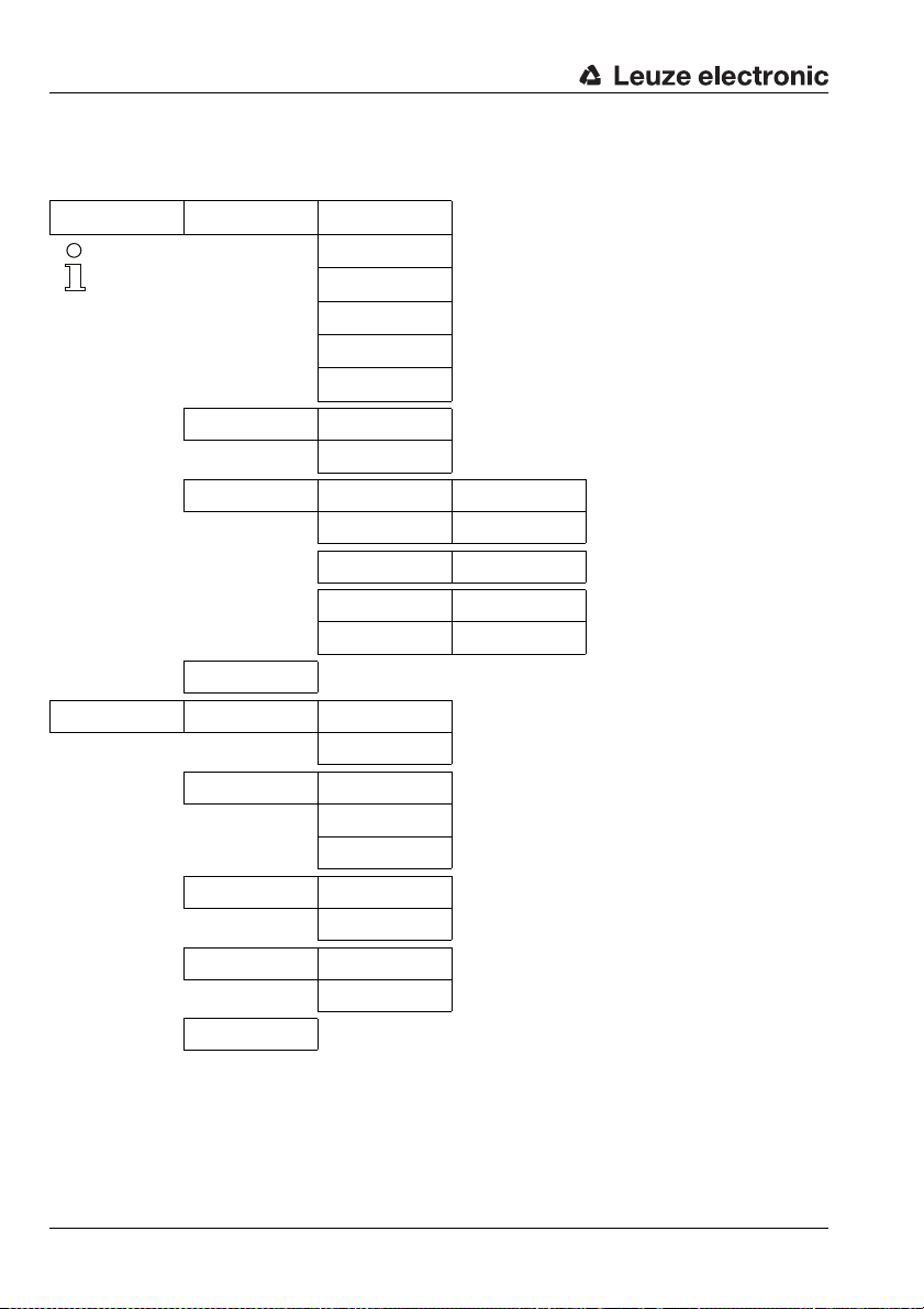
3.7.1 Configuration / menu structure ODSL 30/V… (analogue)
Level 1 Level 2 Level 3 Level 4 Explanation / Notes Default
Applic. Param. Tmeas Bgnd Rem.
100ms 150 m 6-90 %
Note
The functions under Applic. Param.
are not available until the
Advanced Menu is activated
(see chapter 3.8)
Disp. Resolution
1mm
Offset/Preset Offset Direction
Return
Input Menu Inp. teach Q1/Q2
Teach Out Q1/Q2
Input activ/ref
Referencing
Input Polarity
active HIGH +24V
Teach Mode
slope control
Return
Tmeas Bgnd Rem.
100ms 150 m 6-90 %
Tmeas Bgnd Rem.
80ms 39 m 6-90 %
Tmeas Bgnd Rem.
70ms 9.8 m 6-90 %
Tmeas Bgnd Rem.
50ms 150 m 50-90 %
Tmeas Bgnd Rem.
40ms 39 m 50-90 %
Tmeas Bgnd Rem.
30ms 9.8 m 50-90 %
Disp. Resolution
1mm
Disp. Resolution
0.1mm
... positive
Offsetvalue [mm]
Value: 000000
Presetvalue [mm]
Value: 000000
Preset Calculate
... inactive
Inp. teach Q1/Q2
Teach Out Q1/Q2
Inp. teach Q1/Q2
Input disabled
Input activ/ref
Referencing
Input activ/ref
Activation + Ref
Input activ/ref
Input disabled
Input Polarity
active HIGH +24V
Input Polarity
active LOW 0 V
Teach Mode
slope control
Teach Mode
time control
Offset Direction
... positive
Offset Direction
... negative
Offsetvalue [mm]
act Val. 000000
Presetvalue [mm]
act Val. 000000
Preset Calculate
... active
Measurement time / uniqueness range / object reflectivity
Measurement time / uniqueness range / object reflectivity
Measurement time / uniqueness range / object reflectivity
Measurement time / uniqueness range / object reflectivity
Measurement time / uniqueness range / object reflectivity
Measurement time / uniqueness range / object reflectivity
Display resolution 1mm
Display resolution 0.1mm
Offset sign positive
Offset sign negative
Offset value, entry in mm
Preset value, entry in mm
Trigger of the preset function
Return to level 1
Teach input is activated
Teach input is deactivated
Input is referencing input
Input is activation and referencing input
Input activ is deactivated
All inputs are active high
All inputs are active low
Teach-in, slope controlled
Teach-in, time controlled
Return to level 1
X
X
X
0
0
X
X
X
X
34 ODSL 30 Leuze electronic
Page 37

Description ODSL 30
Level 1 Level 2 Level 3 Level 4 Explanation / Notes Default
Output Q Menu Q1 Function sel. Q1 Upper Sw. Pt.
Return
Analogue Out
Menu
Service Menu Password Check
Exit from Menu
Cal. Ana. Output
Current 4-20mA
Pos for max. val
Value: 005000
Pos for min. val
Value: 000200
Return
inactive
ODSL 30 Serial No
Val: 99999
SW V01.20 YYMMDD
Val: 31024
Parameter YYMMDD
Val: 31024
Interface-Type
Analogue Interface
Return
Value: 001000
Q1 Lower Sw. Pt.
Value: 000199
Q1 Hysteresis
Value: 000020
Q1 light/dark
light switching
Q1 Driver
PNP high active
Return
Cal. Ana. Output
Current 4-20mA
Cal. Ana. Output
Voltage 1-10V
Pos for max. val
act Value: 05000
Pos for min. val
act Value: 00200
Password Check
inactive
Password Check
activated
Q1 Upper Sw. Pt.
act Value: 001000
Q1 Lower Sw. Pt.
act Value: 000199
Q1 Hysteresis
act Value: 00020
Q1 light/dark
light switching
Q1 light/dark
dark switching
Q1 Driver
PNP high active
Q1 Driver
NPN low active
Q1 Driver
PNP/NPN pushpull
Upper switching point of output Q1 in millimetres
Lower switching point of output Q1 in millimetres
Switching hysteresis of output
Q1 in millimeters
Q1 is active if an object is in
the switching range
Q1 is active if no object is
present in the switching range
Q1 is high-side output (PNP)
Q1 is low-side output (NPN)
Q1 is push-pull output
Return to level 2
Return to level 1
Current output calibrated,
Voltage output uncalibrated
Voltage output calibrated,
Current output uncalibrated
Distance [mm], at which the
max.
analogue value is output
Distance [mm], at which the
min. analogue value is output
Return to level 1
Password for menu access not
active
Menu access password active,
password: 165 (n. changeable)
Display of serial number, no
changes possible
Display of software version, no
changes possible
Display of parameter version,
no changes possible
Display of the interface type,
no changes possible
Return to level 1
Return to measurement mode
1000
199
20
X
X
X
5000
200
X
TNT 35/7-24V
Leuze electronic ODSL 30 35
Page 38

Description ODSL 30
3.7.2 Configuration / menu structure ODSL 30/24… (3 switching outputs)
Level 1 Level 2 Level 3 Level 4 Explanation / Notes Default
Applic. Param. Tmeas Bgnd Rem.
100ms 150 m 6-90 %
Note
The functions under Applic. Param.
are not available until the
Advanced Menu is activated
(see chapter 3.8)
Disp. Resolution
1mm
Offset/Preset Offset Direction
Return
Input Menu Inp. teach Q1/Q2
Teach Out Q1/Q2
Input activ/ref
Referencing
Inp. teach Q3
Teach output Q3
Input Polarity
active HIGH +24V
Return
Tmeas Bgnd Rem.
100ms 150 m 6-90 %
Tmeas Bgnd Rem.
80ms 39 m 6-90 %
Tmeas Bgnd Rem.
70ms 9.8 m 6-90 %
Tmeas Bgnd Rem.
50ms 150 m 50-90 %
Tmeas Bgnd Rem.
40ms 39 m 50-90 %
Tmeas Bgnd Rem.
30ms 9.8 m 50-90 %
Disp. Resolution
1mm
Disp. Resolution
0.1mm
... positive
Offsetvalue [mm]
Value: 000000
Presetvalue [mm]
Value: 000000
Preset Calculate
... inactive
Inp. teach Q1/Q2
Teach Out Q1/Q2
Inp. teach Q1/Q2
Input disabled
Input activ/ref
Referencing
Input activ/ref
Activation + Ref
Input activ/ref
Input disabled
Inp. teach Q3
Teach Output Q3
Inp. teach Q3
Input disabled
Input Polarity
active HIGH +24V
Input Polarity
active LOW 0 V
Offset Direction
... positive
Offset Direction
... negative
Offsetvalue [mm]
act Val. 000000
Presetvalue [mm]
act Val. 000000
Preset Calculate
... active
Measurement time / uniqueness range / object reflectivity
Measurement time / uniqueness range / object reflectivity
Measurement time / uniqueness range / object reflectivity
Measurement time / uniqueness range / object reflectivity
Measurement time / uniqueness range / object reflectivity
Measurement time / uniqueness range / object reflectivity
Display resolution 1mm
Display resolution 0.1mm
Offset sign positive
Offset sign negative
Offset value, entry in mm
Preset value, entry in mm
Trigger of the preset function
Return to level 1
Teach input is activated
Teach input is deactivated
Input is referencing input
Input is activation and referencing input
Input activ is deactivated
Teach input is activated
Teach input is deactivated
All inputs are active high
All inputs are active low
Return to level 1
X
X
X
0
0
X
X
X
X
36 ODSL 30 Leuze electronic
Page 39

Description ODSL 30
Level 1 Level 2 Level 3 Level 4 Explanation / Notes Default
Output Q Menu Q1 Function sel. Q1 Upper Sw. Pt.
Q2 Function sel. Q2 Upper Sw. Pt.
Q3 Function sel. Q3 Upper Sw. Pt.
Return
Value: 001000
Q1 Lower Sw. Pt.
Value: 000199
Q1 Hysteresis
Value: 000020
Q1 light/dark
light switching
Q1 Driver
PNP high active
Return
Value: 001500
Q2 Lower Sw. Pt.
Value: 000199
Q2 Hysteresis
Value: 000020
Q2 light/dark
light switching
Q2 Driver
PNP high active
Return
Value: 002000
Q3 Lower Sw. Pt.
Value: 000199
Q3 Hysteresis
Value: 000020
Q3 light/dark
light switching
Q3 Driver
PNP high active
Return
Q1 Upper Sw. Pt.
act Value: 001000
Q1 Lower Sw. Pt.
act Value: 000199
Q1 Hysteresis
act Value: 00020
Q1 light/dark
light switching
Q1 light/dark
dark switching
Q1 Driver
PNP high active
Q1 Driver
NPN low active
Q1 Driver
PNP/NPN pushpull
Q2 Upper Sw. Pt.
act Value: 001500
Q2 Lower Sw. Pt.
act Value: 000199
Q2 Hysteresis
act Value: 00020
Q2 light/dark
light switching
Q2 light/dark
dark switching
Q2 Driver
PNP high active
Q2 Driver
NPN low active
Q2 Driver
PNP/NPN pushpull
Q3 Upper Sw. Pt.
act Value: 002000
Q3 Lower Sw. Pt.
act Value: 000199
Q3 Hysteresis
act Value: 00020
Q3 light/dark
light switching
Q3 light/dark
dark switching
Q3 Driver
PNP high active
Q3 Driver
NPN low active
Q3 Driver
PNP/NPN pushpull
Upper switching point of output Q1 in millimetres
Lower switching point of output Q1 in millimetres
Switching hysteresis of output
Q1 in millimeters
Q1 is active if an object is in
the switching range
Q1 is active if no object is
present in the switching range
Q1 is high-side output (PNP)
Q1 is low-side output (NPN)
Q1 is push-pull output
Return to level 2
Upper switching point of output Q2 in millimetres
Lower switching point of output Q2 in millimetres
Switching hysteresis of output
Q2 in millimetres
Q2 is active if an object is
present in the switching range
Q2 is active if no object is
present in the switching range
Q2 is high-side output (PNP)
Q2 is low-side output (NPN)
Q2 is push-pull output
Return to level 2
Upper switching point of output Q3 in millimetres
Lower switching point of output Q3 in millimetres
Switching hysteresis of output
Q3 in millimetres
Q3 is active if an object is
present in the switching range
Q3 is active if no object is
present in the switching range
Q3 is high-side output (PNP)
Q3 is low-side output (NPN)
Q3 is push-pull output
Return to level 2
Return to level 1
1000
199
20
X
X
1500
199
20
X
X
2000
199
20
X
X
TNT 35/7-24V
Leuze electronic ODSL 30 37
Page 40

Description ODSL 30
Level 1 Level 2 Level 3 Level 4 Explanation / Notes Default
Service Menu Password Check
Exit from Menu
inactive
ODSL 30 Serial No
Val: 99999
SW V01.20 YYMMDD
Val: 31024
Parameter YYMMDD
Val: 31024
Interface-Type
3 Outp. Q1-Q2-Q3
Return
Password Check
inactive
Password Check
activated
Password for menu access not
active
Menu access password active,
password: 165 (n. changeable)
Display of serial number, no
changes possible
Display of software version, no
changes possible
Display of parameter version,
no changes possible
Display of the interface type,
no changes possible
Return to level 1
Return to measurement mode
X
38 ODSL 30 Leuze electronic
Page 41

Description ODSL 30
3.7.3 Configuration / menu structure ODSL 30/D 232… (digital RS 232)
Level 1 Level 2 Level 3 Level 4 Explanation / Notes Default
Applic. Param. Tmeas Bgnd Rem.
100ms 150 m 6-90 %
Note
The functions under Applic. Param.
are not available until the
Advanced Menu is activated
(see chapter 3.8)
Disp. Resolution
1mm
Offset/Preset Offset Direction
Return
Input Menu Inp. teach Q1/Q2
Teach Out Q1/Q2
Input activ/ref
Referencing
Input Polarity
active HIGH +24V
Return
Tmeas Bgnd Rem.
100ms 150 m 6-90 %
Tmeas Bgnd Rem.
80ms 39 m 6-90 %
Tmeas Bgnd Rem.
70ms 9.8 m 6-90 %
Tmeas Bgnd Rem.
50ms 150 m 50-90 %
Tmeas Bgnd Rem.
40ms 39 m 50-90 %
Tmeas Bgnd Rem.
30ms 9.8 m 50-90 %
Disp. Resolution
1mm
Disp. Resolution
0.1mm
... positive
Offsetvalue [mm]
Value: 000000
Presetvalue [mm]
Value: 000000
Preset Calculate
... inactive
Inp. teach Q1/Q2
Teach Out Q1/Q2
Inp. teach Q1/Q2
Input disabled
Input activ/ref
Referencing
Input activ/ref
Activation + Ref
Input activ/ref
Input disabled
Input Polarity
active HIGH +24V
Input Polarity
active LOW 0 V
Offset Direction
... positive
Offset Direction
... negative
Offsetvalue [mm]
act Val. 000000
Presetvalue [mm]
act Val. 000000
Preset Calculate
... active
Measurement time / uniqueness range / object reflectivity
Measurement time / uniqueness range / object reflectivity
Measurement time / uniqueness range / object reflectivity
Measurement time / uniqueness range / object reflectivity
Measurement time / uniqueness range / object reflectivity
Measurement time / uniqueness range / object reflectivity
Display resolution 1mm
Display resolution 0.1mm
Offset sign positive
Offset sign negative
Offset value, entry in mm
Preset value, entry in mm
Trigger of the preset function
Return to level 1
Teach input is activated
Teach input is deactivated
Input is referencing input
Input is activation and referencing input
Input activ is deactivated
All inputs are active high
All inputs are active low
Return to level 1
X
X
X
0
0
X
X
TNT 35/7-24V
X
Leuze electronic ODSL 30 39
Page 42

Description ODSL 30
Level 1 Level 2 Level 3 Level 4 Explanation / Notes Default
Output Q Menu Q1 Function sel. Q1 Upper Sw. Pt.
Q2 Function sel. Q2 Upper Sw. Pt.
Return
Value: 001000
Q1 Lower Sw. Pt.
Value: 000199
Q1 Hysteresis
Value: 000020
Q1 light/dark
light switching
Q1 Driver
PNP high active
Return
Value: 001500
Q2 Lower Sw. Pt.
Value: 000199
Q2 Hysteresis
Value: 000020
Q2 light/dark
light switching
Q2 Driver
PNP high active
Return
Q1 Upper Sw. Pt.
act Value: 001000
Q1 Lower Sw. Pt.
act Value: 000199
Q1 Hysteresis
act Value: 00020
Q1 light/dark
light switching
Q1 light/dark
dark switching
Q1 Driver
PNP high active
Q1 Driver
NPN low active
Q1 Driver
PNP/NPN pushpull
Q2 Upper Sw. Pt.
act Value: 001500
Q2 Lower Sw. Pt.
act Value: 000199
Q2 Hysteresis
act Value: 00020
Q2 light/dark
light switching
Q2 light/dark
dark switching
Q2 Driver
PNP high active
Q2 Driver
NPN low active
Q2 Driver
PNP/NPN pushpull
Upper switching point of output Q1 in millimetres
Lower switching point of output Q1 in millimetres
Switching hysteresis of output
Q1 in millimeters
Q1 is active if an object is in
the switching range
Q1 is active if no object is
present in the switching range
Q1 is high-side output (PNP)
Q1 is low-side output (NPN)
Q1 is push-pull output
Return to level 2
Upper switching point of output Q2 in millimetres
Lower switching point of output Q2 in millimetres
Switching hysteresis of output
Q2 in millimetres
Q2 is active if an object is
present in the switching range
Q2 is active if no object is
present in the switching range
Q2 is high-side output (PNP)
Q2 is low-side output (NPN)
Q2 is push-pull output
Return to level 2
Return to level 1
1000
199
20
X
X
1500
199
20
X
X
40 ODSL 30 Leuze electronic
Page 43

Description ODSL 30
Level 1 Level 2 Level 3 Level 4 Explanation / Notes Default
Serial COM Menu COM Function sel
Service Menu Password Check
Exit from Menu
ASCII Distance
Node Address
Value: 000
Baudrate COM
Baudrate 9600
Stopbits COM
1
Return
inactive
ODSL 30 Serial No
Val: 99999
SW V01.20 YYMMDD
Val: 31024
Parameter YYMMDD
Val: 31024
Interface-Type
RS 232 Interface
Return
COM Function sel
ASCII Distance
COM Function sel
ASCII Dist. .1mm
COM Function sel
Distance 14 bit
COM Function sel
Distance 16 bit
COM Function sel
Distance 20bit
COM Function sel
Remote Control
COM Function sel
switched OFF
Node Address
act Value: 000
Baudrate COM
Baudrate 9600
Baudrate COM
Baudrate 19200
Baudrate COM
Baudrate 28800
Baudrate COM
Baudrate 38400
Baudrate COM
Baudrate 57600
Baudrate COM
Baudrate 115200
Baudrate COM
Baudrate 600
Baudrate COM
Baudrate 1200
Baudrate COM
Baudrate 2400
Baudrate COM
Baudrate 4800
Stopbits COM
1
Stopbits COM
2
Password Check
inactive
Password Check
activated
Serial transmission, output in
ASCII, 5 bytes, resolut. 1mm
Serial transmission, output in
ASCII, 6 bytes, resolut. 0.1mm
Serial transmission, 2 bytes,
15m meas. range, res. 1 mm
Serial transmission, 3 bytes,
30m meas. range, res. 1 mm
Serial transmission, 4 bytes,
30m meas. range, res. 0.1 mm
Remote control activated,
RS 232 no bus operation
Serial data transmission deactivated
Node address 0 … 14
Baud rate 9600 bit/s
Baud rate 19200 bit/s
Baud rate 28800 bit/s
Baud rate 38400 bit/s
Baud rate 57600 bit/s
Baud rate 115200 bit/s
Baud rate 600 bit/s
Baud rate 1200 bit/s
Baud rate 2400 bit/s
Baud rate 4800 bit/s
Number of stop bits: 1
Number of stop bits: 2
Return to level 1
Password for menu access not
active
Menu access password active,
password: 165 (n. changeable)
Display of serial number, no
changes possible
Display of software version, no
changes possible
Display of parameter version,
no changes possible
Display of the interface type,
no changes possible
Return to level 1
Return to measurement mode
X
0
X
X
TNT 35/7-24V
X
Leuze electronic ODSL 30 41
Page 44
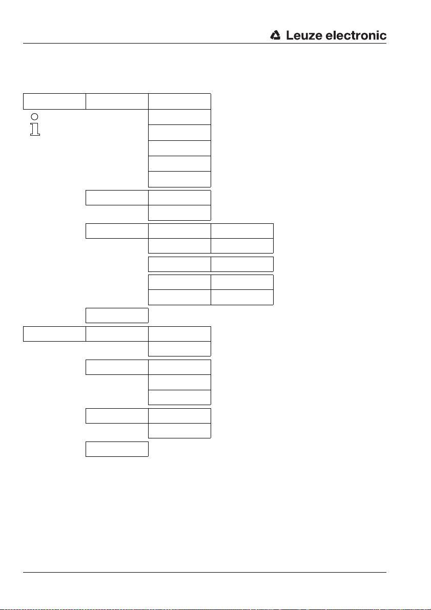
Description ODSL 30
3.7.4 Configuration / menu structure ODSL 30/D 485… (digital RS 485)
Level 1 Level 2 Level 3 Level 4 Explanation / Notes Default
Applic. Param. Tmeas Bgnd Rem.
100ms 150 m 6-90 %
Note
The functions under Applic. Param.
are not available until the
Advanced Menu is activated
(see chapter 3.8)
Disp. Resolution
1mm
Offset/Preset Offset Direction
Return
Input Menu Inp. teach Q1/Q2
Teach Out Q1/Q2
Input activ/ref
Referencing
Input Polarity
active HIGH +24V
Return
Tmeas Bgnd Rem.
100ms 150 m 6-90 %
Tmeas Bgnd Rem.
80ms 39 m 6-90 %
Tmeas Bgnd Rem.
70ms 9.8 m 6-90 %
Tmeas Bgnd Rem.
50ms 150 m 50-90 %
Tmeas Bgnd Rem.
40ms 39 m 50-90 %
Tmeas Bgnd Rem.
30ms 9.8 m 50-90 %
Disp. Resolution
1mm
Disp. Resolution
0.1mm
... positive
Offsetvalue [mm]
Value: 000000
Presetvalue [mm]
Value: 000000
Preset Calculate
... inactive
Inp. teach Q1/Q2
Teach Out Q1/Q2
Inp. teach Q1/Q2
Input disabled
Input activ/ref
Referencing
Input activ/ref
Activation + Ref
Input activ/ref
Input disabled
Input Polarity
active HIGH +24V
Input Polarity
active LOW 0 V
Offset Direction
... positive
Offset Direction
... negative
Offsetvalue [mm]
act Val. 000000
Presetvalue [mm]
act Val. 000000
Preset Calculate
... active
Measurement time / uniqueness range / object reflectivity
Measurement time / uniqueness range / object reflectivity
Measurement time / uniqueness range / object reflectivity
Measurement time / uniqueness range / object reflectivity
Measurement time / uniqueness range / object reflectivity
Measurement time / uniqueness range / object reflectivity
Display resolution 1mm
Display resolution 0.1mm
Offset sign positive
Offset sign negative
Offset value, entry in mm
Preset value, entry in mm
Trigger of the preset function
Return to level 1
Teach input is activated
Teach input is deactivated
Input is referencing input
Input is activation and referencing input
Input activ is deactivated
All inputs are active high
All inputs are active low
Return to level 1
X
X
X
0
0
X
X
X
42 ODSL 30 Leuze electronic
Page 45

Description ODSL 30
Level 1 Level 2 Level 3 Level 4 Explanation / Notes Default
Output Q Menu Q1 Function sel. Q1 Upper Sw. Pt.
Q2 Function sel. Q2 Upper Sw. Pt.
Return
Value: 001000
Q1 Lower Sw. Pt.
Value: 000199
Q1 Hysteresis
Value: 000020
Q1 light/dark
light switching
Q1 Driver
PNP high active
Return
Value: 001500
Q2 Lower Sw. Pt.
Value: 000199
Q2 Hysteresis
Value: 000020
Q2 light/dark
light switching
Q2 Driver
PNP high active
Return
Q1 Upper Sw. Pt.
act Value: 001000
Q1 Lower Sw. Pt.
act Value: 000199
Q1 Hysteresis
act Value: 00020
Q1 light/dark
light switching
Q1 light/dark
dark switching
Q1 Driver
PNP high active
Q1 Driver
NPN low active
Q1 Driver
PNP/NPN pushpull
Q2 Upper Sw. Pt.
act Value: 001500
Q2 Lower Sw. Pt.
act Value: 000199
Q2 Hysteresis
act Value: 00020
Q2 light/dark
light switching
Q2 light/dark
dark switching
Q2 Driver
PNP high active
Q2 Driver
NPN low active
Q2 Driver
PNP/NPN pushpull
Upper switching point of output Q1 in millimetres
Lower switching point of output Q1 in millimetres
Switching hysteresis of output
Q1 in millimeters
Q1 is active if an object is in
the switching range
Q1 is active if no object is
present in the switching range
Q1 is high-side output (PNP)
Q1 is low-side output (NPN)
Q1 is push-pull output
Return to level 2
Upper switching point of output Q2 in millimetres
Lower switching point of output Q2 in millimetres
Switching hysteresis of output
Q2 in millimetres
Q2 is active if an object is
present in the switching range
Q2 is active if no object is
present in the switching range
Q2 is high-side output (PNP)
Q2 is low-side output (NPN)
Q2 is push-pull output
Return to level 2
Return to level 1
1000
199
20
X
X
1500
199
20
X
X
TNT 35/7-24V
Leuze electronic ODSL 30 43
Page 46

Description ODSL 30
Level 1 Level 2 Level 3 Level 4 Explanation / Notes Default
Serial COM Menu COM Function sel
Service Menu Password Check
Exit from Menu
ASCII Distance
Node Address
Value: 000
Baudrate COM
Baudrate 9600
Stopbits COM
1
Return
inactive
ODSL 30 Serial No
Val: 99999
SW V01.20 YYMMDD
Val: 31024
Parameter YYMMDD
Val: 31024
Interface-Type
RS 485 Interface
Return
COM Function sel
ASCII Distance
COM Function sel
ASCII Dist. .1mm
COM Function sel
Distance 14 bit
COM Function sel
Distance 16 bit
COM Function sel
Distance 20bit
COM Function sel
Remote Control
COM Function sel
switched OFF
Node Address
act Value: 000
Baudrate COM
Baudrate 9600
Baudrate COM
Baudrate 19200
Baudrate COM
Baudrate 28800
Baudrate COM
Baudrate 38400
Baudrate COM
Baudrate 57600
Baudrate COM
Baudrate 115200
Baudrate COM
Baudrate 600
Baudrate COM
Baudrate 1200
Baudrate COM
Baudrate 2400
Baudrate COM
Baudrate 4800
Stopbits COM
1
Stopbits COM
2
Password Check
inactive
Password Check
activated
Serial transmission, output in
ASCII, 5 bytes, resolut. 1mm
Serial transmission, output in
ASCII, 6 bytes, resolut. 0.1mm
Serial transmission, 2 bytes,
15m meas. range, res. 1 mm
Serial transmission, 3 bytes,
30m meas. range, res. 1 mm
Serial transmission, 4 bytes,
30m meas. range, res. 0.1 mm
Remote control activated via
bus commands
Serial data transmission deactivated
Node address 0 … 14
Baud rate 9600 bit/s
Baud rate 19200 bit/s
Baud rate 28800 bit/s
Baud rate 38400 bit/s
Baud rate 57600 bit/s
Baud rate 115200 bit/s
Baud rate 600 bit/s
Baud rate 1200 bit/s
Baud rate 2400 bit/s
Baud rate 4800 bit/s
Number of stop bits: 1
Number of stop bits: 2
Return to level 1
Password for menu access not
active
Menu access password active,
password: 165 (n. changeable)
Display of serial number, no
changes possible
Display of software version, no
changes possible
Display of parameter version,
no changes possible
Display of the interface type,
no changes possible
Return to level 1
Return to measurement mode
X
0
X
X
X
44 ODSL 30 Leuze electronic
Page 47

3.7.5 Operating example
ENTER
ENTER
ENTER
ENTER
The following values are to be configured for an ODSL 30/V…:
• calibrated current output 4 … 20 mA, characteristic curve with positive gradient and
measurement range 500 … 3500mm.
• upper switching point for output Q1 at 3000mm and
lower switching point for output Q1 at 2000mm.
The device is set to factory settings and is in measurement mode.
Configuring the calibrated current output
Action Display Explanation / Notes
Press an arbitrary key , , or .
ENTER
Input Menu
Description ODSL 30
You get to the configuration menu for the
ODSL 30…
Press the keys and to change to the
menu item "Analog Out Menu".
Select menu item with the key.
Press the keys and to change to the
menu item "Pos for min. val".
ENTER
Press the key to edit the value.
Press the and keys to change the present value to "500".
Apply the new value by pressing the key.
Save the new value by pressing the key.
Press the keys and to change to the
menu item "Pos for max. val".
ENTER
Press the key to edit the value.
Press the and keys to change the present value to "3500".
Apply the new value by pressing the key.
ENTER
Save the new value by pressing the key.
Change to the menu item "Return" by pressing
the and keys.
Analogue Out
Menu
Cal Ana. Output
Current 4-20mA
Pos for min. val
Value: 000200
Pos for min. val
act Value: 00200
Pos for min. val
new Value->00500
to store press
new Val.: 00500
Pos for min. val
Value: 000500
Pos for max. val
Value: 005000
Pos for max. val
act Value: 05000
Pos for max. val
new Value->03500
to store press
new Val.: 03500
Pos for max. val
Value: 003500
Return
This menu item configures the analogue
output.
Current output 4 … 20mA is already set
as the calibrated output.
This menu item sets the distance value for
the minimum analogue value.
Ready for editing.
New value has been edited.
Applying.
Saving.
This menu item sets the distance value for
the maximum analogue value.
Ready for editing.
New value has been edited.
Applying.
Saving.
This menu item leads to the parent level.
TNT 35/7-24V
Leuze electronic ODSL 30 45
Page 48

Description ODSL 30
ENTER
ENTER
ENTER
ENTER
ENTER
ENTER
ENTER
ENTER
ENTER
ENTER
Action Display Explanation / Notes
Select menu item with the key.
Press the keys and to change to the
menu item "Exit from Menu".
Select menu item with the key.
Configuring switching points Q1
Action Display Explanation / Notes
Press an arbitrary key , , or .
Press the keys and to change to the
menu item "Output Q Menu".
Select menu item with the key.
Select menu item with the key.
Press the key to edit the value.
Press the and keys to change the present value to "3000".
Apply the new value by pressing the key.
Analogue Out
Menu
Exit from Menu
Leuze electronic
Dist. [mm] 10687
Input Menu
Output Q Menu
Q1 Function sel.
Q1 Upper Sw. Pt.
Value: 001000
Q1 Upper Sw. Pt.
act Value: 001000
Q1 Upper Sw. Pt.
new Value->003000
to store press
new
Val.: 003000
Menu level 1.
This menu item exits the
configuration menu.
The device has returned to measurement
mode
You get to the configuration menu for the
ODSL 30…
This menu item configures the switching
outputs.
This menu item configures the switching
output Q1.
This menu item configures the upper
switching point for output Q1.
Ready for editing.
New value has been edited.
Applying.
Save the new value by pressing the key.
Press the keys and to change to the
menu item
"Q1 Lower Sw. Pt.".
Press the key to edit the value.
Press the and keys to change the present value to "2000".
Apply the new value by pressing the key.
ENTER
Save the new value by pressing the key.
Q1 Upper Sw. Pt.
Value: 003000
Q1 Lower Sw. Pt.
Value: 000199
Q1 Lower Sw. Pt.
act Value: 000199
Q1 Lower Sw. Pt.
new Value->002000
to store press
new
Val.: 002000
Q1 Lower Sw. Pt.
Value: 002000
Saving.
This menu item configures the lower
switching point for output Q1.
Ready for editing.
New value has been edited.
Applying.
Saving.
46 ODSL 30 Leuze electronic
Page 49

Description ODSL 30
Change to the menu item "Return" by pressing
Action Display Explanation / Notes
the and keys.
Select menu item with the key.
ENTER
Change to the menu item "Return" by pressing
the and keys.
Select menu item with the key.
Press the keys and to change to the
menu item "Exit from Menu".
Select menu item with the key.
ENTER
ENTER
Return
Q1 Function sel.
Return
Output Q Menu
Exit from Menu
Leuze electronic
Dist. [mm] 10687
This menu item leads to the parent level.
Menu level 2.
This menu item leads to the parent level.
Menu level 1.
This menu item exits the
configuration menu.
The device has returned to measurement
mode
Leuze electronic ODSL 30 47
TNT 35/7-24V
Page 50

Description ODSL 30
ENTER
ENTER
3.8 Advanced Menu (for software versions V01.10 and newer)
Notice!
For information on querying the device software version, see chapter 3.6.5.
In addition to the described functions, additional, new functions are available in the
Advanced Menu:
• Setting an offset/preset value to compensate for mounting tolerances
• Reduction in measurement time to as little as 30 ms
• Changing the display resolution
Also available in the Advanced Menu is the menu item Applic. Param.. This can be used
to change the measurement value output of the ODSL 30.
Notice!
To protect against unintentional access, the Advanced Menu is hidden from view by default
and must first be activated by the user.
Attention!
Please be certain to read the following notices before you activate the advanced mode and
change parameters in the menu item Applic. Param..
Activation of the advanced mode
Hold down the button during measurement operation for longer than 5s.
The Advanced Menu? display appears.
Press the or button to cancel activation of the Advanced Menu.
Confirm Yes by pressing the button.
The Advanced Menu is activated now display appears briefly.
The menu item Applic. Param. is now also available in menu level 1.
3.8.1 Setting an Offset/Preset Value - Compensating for Mounting Tolerances
Deviations which occur during mounting of the ODSL 30 can be compensated for with the
offset or preset parameter:
•For Offset, a fixed value and sign are specified.
•For Preset, a nominal measurement value is specified; a measurement is then per-
formed using an object located at the desired nominal distance.
Attention!
If the offset or preset results in negative measurement values, zero is output at the interface
and on the display.
48 ODSL 30 Leuze electronic
Page 51

Description ODSL 30
ENTER
Setting the offset
Configuration is performed using the keypad and display:
Applic. Param. -> Offset/Preset
The following can be entered:
• Offset Direction
Selection... positive or ... negative, i.e. specifies whether the offset value is
added to or subtracted from the measurement value.
• Offsetvalue [mm]
Enter the offset value.
The set offset value is subtracted from the calculated (digital) measurement value of the
sensor if negative was set for the Offset Direction.
Example:
Measurement value of the ODSL 30: 1500 mm,
Input: Offsetvalue: 100mm,
Offset Direction: … negative
Output on the display and at the interface: 1400mm
Setting the preset
Configuration is performed using the keypad and display:
Applic. Param. -> Offset/Preset
Procedure for setting a preset value:
• Enter nominal value -> Presetvalue [mm]
• In menu item Preset calculate, select the option ... active
• Press the button to confirm.
A measurement is made, the preset is stored and the ODSL 30 is ready.
The offset value is automatically calculated from the measurement value and nominal
measurement value (preset value) and entered as the offset in the configuration. A preset
is deactivated by entering an offset value of zero.
TNT 35/7-24V
Example:
Input: Preset value: 1400mm,
Object dist. 1300mm in front of ODSL 30: Preset Calculation ...active, trigger
measurement, an offset of +100mm
is automatically stored
Object distance 1300mm: Output on display and at interface: 1400mm
Object distance 1400mm: Output on display and at interface: 1500mm
Leuze electronic ODSL 30 49
Page 52

Description ODSL 30
3.8.2 Reduction in Measurement Time to as Little as 30ms
Definition of uniqueness range
Due to the periodicity of the sinusoid, the phasing of the signals received by the ODSL 30
limits the determination of unique measurement values to within a specific interval. The
length of this interval is called the uniqueness range. A large uniqueness range is equivalent
to high background suppression.
Relationship between uniqueness range - luminosity coefficient - measurement
time
In the default setting (uniqueness range 150m, measurement on both light as well as dark
objects with luminosity coefficients of 6 … 90%), the measurement time is 100ms.
By limiting the uniqueness range and the luminosity coefficient (measurements on only light
objects with luminosity coefficients of 50 … 90 %), the measurement time can be reduced to
as little as 30ms.
Configuration is performed using the keypad and display:
Applic. Param. -> Tmeas Bgnd Rem.
Changes to these variables yield measurement times as shown in the following table:
Meas.
time [ms]
30 9.8
40 39 40ms 39 m 50-90 %
50 150 50ms 150 m 50-90 %
70 9.8
80 39 80ms 39 m 6-90 %
100
1) Default setting
Notice!
By using the cooperative target CTS 100 x 100 (Part No. 501 04599), you ensure that the luminosity coefficient on the surface being measured is 50 … 90%.
Attention!
If an object is located at a distance greater than the preselected uniqueness range, incorrect
measurements will result (provided the reception signal is sufficiently high)!
50 ODSL 30 Leuze electronic
1)
Uniqueness
range [m]
150 100ms 150 m 6-90 %
Object luminosity
coefficient [%]
50 … 90
(light objects)
6 … 90
(light and dark objects)
Setting in the menu item
Tmeas Bgnd Rem.
30ms 9.8 m 50-90 %
70ms 9.8 m 6-90 %
Page 53

Example:
Measurement value [m]
Distance [m]
Uniqueness range 9.8m
With a uniqueness range of 9.8m, an object is located at a distance of 1 m. The sensor
outputs a correct measurement value of 1m.
If the object is located at a distance of 10.8m or 20.6m or 30.4m etc. from the sensor, the
sensor outputs an incorrect measurement value of 1m, i.e. a correct measurement value is
only output for objects located within the uniqueness range.
20
10
0
10 20 30 40 50
0
Figure 3.11:ODSL 30 measurement values with a uniqueness range of 9.8 m
3.8.3 Changing the Display Resolution
Description ODSL 30
60
On delivery, the measurement resolution of the ODSL 30 (display) is 1mm. In the advanced
mode, the resolution of the display can be increased to 0.1mm by configuring with the
keypad and display:
Applic. Param. -> Disp. Resolution 0.1mm.
Notice!
This menu item refers only to the display. Changing this parameter has no direct effect
on the output at the serial or analogue interfaces.
If you would like to transmit measurement data with a resolution of 0.1 mm using the
ODSL 30/D... with serial interface, this can be parameterized at a different location
(see chapter 3.4.3).
For the ODSL 30/V…, the measurement range is to be restricted by appropriately configuring the analogue output.
The configuration of a resolution of 0.1 mm is useful when performing measurements on
objects with high diffuse reflection and when the measurement data are processed further
Leuze electronic ODSL 30 51
(e.g. averaging).
TNT 35/7-24V
Page 54
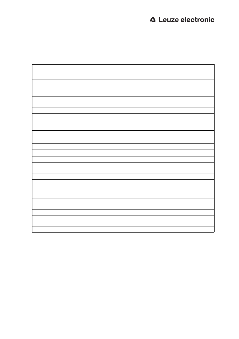
Technical Data ODSL 30
4 Technical Data ODSL 30
4.1 General specifications
Optical data
Measurement range 200 … 30000mm (6 … 90% diffuse reflection)
200 … 65000mm (50 … 90% diffuse reflection, only
Resolution
1)
Light source laser (modulated light)
Wavelength 655nm (visible red light)
Laser class 2 (in accordance with EN 60825-1)
Light spot diameter divergent, Ø 6mm at a distance of 10m
Minimum object size 50x 50 mm
Timing
Measurement time
Delay before start-up 1s
Mechanical data
Housing metal
Optics cover glass
Weight 650g
Connection type M12 connector, 8-pin
Environmental data
Ambient temperature
(operation
Ambient light limit £ 5 kLux
Protective circuit
VDE safety class
3)
/storage)
4)
5)
Protection class IP 67
Standards applied IEC 60947-5-2
Certifications UL508,C22.2 No.14-13
1) Resolution on the LC display
2) Configurable, depends on the reflectivity of the object and on the max. detection range
3) After an operating time of 30 min., the device has reached the operating temperature
required for an optimal measurement.
4) 2=polarity reversal protection, 3=short-circuit protection for all outputs
5) Rating voltage 250VAC
6) For UL applications: only for use in "Class 2" electrical circuits according to NEC
7) These sensors shall be used with UL Listed Cable assemblies rated 30 V, 0.5 A min,
in the field installation, or equivalent (categories: CYJV/CYJV7 or PVVA/PVVA7)
ODSL 30/D…)
0.1mm/1 mm (factory setting)
2)
30 … 100ms (factory setting: 100ms)
-10 … +45 °C / -40 … +70 °C
2, 3
II, all-insulated
ODSL 30
2
at a distance of 10m (6 … 90% diffuse reflection)
6) 7)
52 ODSL 30 Leuze electronic
Page 55

4.2 Device-specific data
4.2.1 ODSL 30/V-30M-S12
Electrical data
Operating voltage U
Residual ripple 15% of U
Power consumption 4W
Switching output
Signal voltage high/low (U
Output current max. 100 mA
Analog output
Error limits
Absolute measurement
accuracy
4)
5)
Repeatability
1) For UL applications: only for use in "Class 2" electrical circuits according to NEC
2) LC display and keypad at the device for configuration
3) The current output (default) or the voltage output is calibrated
4) In the temperature range of 0°C … +45°C, measurement object 50x50mm²;
at temperatures < 0°C different error limits apply;
5) luminosity coefficient 6% … 90%, temperature range 0°C … +45°C
6) Same object, identical environmental conditions, measurement object 50 x 50mm
2) 3)
6)
1)
B
2)
Technical Data ODSL 30
ODSL 30/V-30M-S12
18 … 30VDC (incl. residual ripple)
B
1 PNP transistor output, HIGH active (default),
NPN transistor or push-pull through configuration
- 2V) / 2V
B
per transistor output
1 voltage output 1 … 10V (RL 2kOhm)
1 current output 4 … 20mA (R
measurement range up to 2.5m:
± 2% without referencing, ± 1% with referencing
measurement range 2.5m up to 5m:
± 1.5% without referencing, ± 1% with referencing
measurement range 5m up to 30m:
± 1% without referencing, ± 1% with referencing
± 0.5% of measurement value
500Ohm)
L
2
Leuze electronic ODSL 30 53
TNT 35/7-24V
Page 56

Technical Data ODSL 30
4.2.2 ODSL 30/24-30M-S12
Electrical data
Operating voltage U
Residual ripple 15% of U
Power consumption 4W
Switching outputs
Signal voltage high/low (U
Output current max. 100mA
Error limits
Absolute measurement
accuracy
3)
4)
Repeatability
1) For UL applications: only for use in "Class 2" electrical circuits according to NEC
2) LC display and keypad at the device for configuration
3) In the temperature range of 0°C … +45°C, measurement object 50x50mm²;
at temperatures < 0°C different error limits apply;
4) Luminosity coefficient 6% … 90%, temperature range 0°C … +45°C
5) Same object, identical environmental conditions
1)
B
2)
5)
ODSL 30/24-30M-S12
10 … 30V DC (incl. residual ripple)
B
3 PNP transistor outputs, HIGH active (default),
NPN transistor or push-pull through configuration
- 2V) / 2V
B
per transistor output
± 5mm (6% diffuse reflection)
± 2mm (90% diffuse reflection) after referencing
± 2mm (6 … 90% diffuse reflection)
54 ODSL 30 Leuze electronic
Page 57

4.2.3 ODSL 30/D 232-30M-S12
Electrical data
Operating voltage U
Residual ripple 15% of U
Power consumption 4W
Switching outputs
Signal voltage high/low (U
Output current max. 100 mA
Serial interface RS 232, 9600 Baud (default),
Transmission protocol see chapter 3.4.3
Error limits
Absolute measurement
accuracy
3)
4)
Repeatability
1) For UL applications: only for use in "Class 2" electrical circuits according to NEC
2) LC display and keypad at the device for configuration
3) In the temperature range of 0°C … +45°C, measurement object 50x50mm²;
at temperatures < 0°C different error limits apply;
4) Diffuse reflectance 6% … 90%, temperature range 0°C … +45°C
5) Same object, identical environmental conditions
1)
B
2)
5)
Technical Data ODSL 30
ODSL 30/D 232-30M-S12
10 … 30VDC (incl. residual ripple)
B
2 PNP transistor outputs, HIGH active (default),
NPN transistor or push-pull through configuration
- 2V) / 2V
B
per transistor output
baud rate configurable
±5mm (6 … 90% diffuse reflection),
±2mm (90% diffuse reflection) after referencing
± 2mm (6 … 90% diffuse reflection)
Leuze electronic ODSL 30 55
TNT 35/7-24V
Page 58

Technical Data ODSL 30
4.2.4 ODSL 30/D 485-30M-S12
Electrical data
Operating voltage U
Residual ripple 15% of U
Power consumption 4W
Switching outputs
Signal voltage high/low (U
Output current max. 100mA
Serial interface RS 485, 9600 Baud (default), no termination,
Transmission protocol see chapter 3.4.3
Error limits
Absolute measurement
accuracy
3)
4)
Repeatability
1) For UL applications: only for use in "Class 2" electrical circuits according to NEC
2) LC display and keypad at the device for configuration
3) In the temperature range of 0°C … +45°C, measurement object 50x50mm²;
at temperatures < 0°C different error limits apply;
4) Diffuse reflectance 6% … 90%, temperature range 0°C … +45°C
5) Same object, identical environmental conditions
1)
B
2)
5)
ODSL 30/D 485-30M-S12
10 … 30V DC (incl. residual ripple)
B
2 PNP transistor outputs, HIGH active (default),
NPN transistor or push-pull through configuration
- 2V) / 2V
B
per transistor output
baud rate configurable
±5mm (6 … 90% diffuse reflection),
±2mm (90% diffuse reflection) after referencing
± 2mm (6 … 90% diffuse reflection)
56 ODSL 30 Leuze electronic
Page 59

4.3 Dimensioned and connection drawings
A 1 green indicator diode / ready
B 3 indicator diodes yellow/switching outputs Q1, Q2, Q3
C Optical axes
D Transmitter
E Receiver
F Reference edge for the measurement (distance zero point)
G Sight for coarse alignment
G
All ODSL 30 variants
Technical Data ODSL 30
Figure 4.1: Dimensioned drawing ODSL 30 variants
Leuze electronic ODSL 30 57
TNT 35/7-24V
Page 60

Technical Data ODSL 30
ODSL 30/V… (analogue output)
Figure 4.2: Electrical Connection ODSL 30/V…
ODSL 30/24… (3 switching outputs)
Figure 4.3: Electrical Connection ODSL 30/24…
ODSL 30/D 232… (digital output RS 232)
Figure 4.4: Electrical Connection ODSL 30/D 232…
58 ODSL 30 Leuze electronic
Page 61

Technical Data ODSL 30
ODSL 30/D 485… (digital output RS 485)
Figure 4.5: Electrical Connection ODSL 30/D 485…
Attention
For UL applications, use is only permitted in class 2 circuits in accordance with the NEC
(National Electric Code).
Leuze electronic ODSL 30 59
TNT 35/7-24V
Page 62

Type overview and accessories
5 Type overview and accessories
5.1 Type overview
Designation Order no. Description
ODSL 30/V-30M-S12 50039447
ODSL 30/24-30M-S12 50040720
ODSL 30/D232-30M-S12 50041203
ODSL 30/D485-30M-S12 50041204
Measurement range 0 … 30000mm,
analog current/voltage output,
1 configurable switching output,
laser class 2
Measurement range: 0 … 30000mm
3 configurable switching outputs,
laser class 2
Measurement range 0 … 65000mm,
RS 232 serial interface,
two configurable switching outputs,
laser class 2
Measurement range 0 … 65000mm,
RS 485 serial interface,
two configurable switching outputs,
laser class 2
Table 5.1: ODSL 30 type overview
60 ODSL 30 Leuze electronic
Page 63

5.2 Accessories
The following accessories are available for the ODSL 30:
Designation Order no. Short descriptions
Connection cables
K-D M12A-8P-2m-PUR 50104591 Connection cable M 12, 8-pin, axial, length 2 m
K-D M12A-8P-5m-PUR 50104590 Connection cable M 12, 8-pin, axial, length 5 m
K-D M12A-8P-10m-PUR 50106882 Connection cable M12, 8-pin, axial, length 10m
CB-M12-15000E-8G 678062 Connection cable M12, 8-pin, axial, length 15m
CB-M12-25000E-8G 678063 Connection cable M12, 8-pin, axial, length 25m
CB-M12-50000E-8G 678064 Connection cable M12, 8-pin, axial, length 50m
User-configurable connectors
KD 01-8-BA 50112157 M12 connector (socket), 8-pin, axial
Cooperative target
CTS 100x100 50104599 Cooperative target, luminosity coefficient 50 … 90%
PC accessories
1)
UPG 5
ODS software
Accessories for fieldbus connection for ODSL 30/D232-30M-S12 with RS 232 interface
MA 204i 50112893
MA 208i 50112892
MA 235i 50114154
MA 238i 50114155
MA 248i 50112891
MA 255i 50114156
MA 258i 50114157
K-DS M12A-MA-8P-3m-S-PUR 50115050
Table 5.2: Accessories ODSL 30
2)
1) Required for the visualization of the measurement values via the ODS software.
2) With the ODSL 30…, this can only be used exclusively for the visualization of measurement values on the PC; configuration is not possible!
Type overview and accessories
50039627 PC-adapter for ODSL30
Free download
from
www.leuze.com
Software for measurement value visualization of the
ODSL 30
Modular fieldbus connection for field use,
interfaces: RS232 / PROFIBUS DP
Modular fieldbus connection for field use,
interfaces: RS232 / Ethernet TCP/IP
Modular fieldbus connection for field use,
interfaces: RS232 / CANopen
Modular fieldbus connection for field use,
interfaces: RS232 / EtherCAT
Modular fieldbus connection for field use,
interfaces: RS232 / PROFINET-IO
Modular fieldbus connection for field use,
interfaces: RS232 / DeviceNet
Modular fieldbus connection for field use,
interfaces: RS232 / Ethernet/IP
Connection cable for ODSL 30/D232-30M-S12 with RS232
to modular interfacing units MA 2xxi, cable length 3 m
TNT 35/7-24V
Notice
In connection with the ODSL 30, the software can only be used for the display of measurement values, but not for the configuration of the device.
Leuze electronic ODSL 30 61
Page 64

Installation
6 Installation
6.1 Storage, transportation
Unpacking
Check the packaging for any damage. If damage is found, notify the post office or ship-
ping agent as well as the supplier.
Check the delivery contents using your order and the delivery papers:
• Delivered quantity
• Device variant and model as indicated on the nameplate
• Accessories
• Operating manual
Save the original packaging for later storage or shipping.
If you have any questions concerning your shipment, please contact your supplier or your
local Leuze electronic sales office.
Observe the applicable local regulations when disposing of the packaging materials.
6.2 Mounting
Notice
The mounting device BT 30 is already included in the delivery package of the ODSL 30.
View through a chase
Figure 6.1: View through a chase
If the ODSL 30 has to be installed behind a cover, the chase has to have at least the size of
the optical glass cover. Otherwise, a correct measurement is not possible or can not be
guaranteed.
62 ODSL 30 Leuze electronic
Page 65

6.3 Teach-in
You can adjust the upper switching points by means of teach-in; with the ODSL 30/V…, you
can also set the characteristic output curve of the analogue output by means of teach-in. For
teach-in, there are differences among the various device variants:
Teach procedure for ODSL 30/V… (1 switching output)
Position the measurement object at the desired distance. Connect the teach input
teach Q1 for 2sec. to +U
output is taught.
Teaching takes place towards the switching point.
These default values are preset:
• Function characteristics of the switching output: "light switching"
• Lower switching point: 199mm
• Upper switching point: 1000mm
• Hysteresis: 20mm
You can change these values using the keypad and LC display.
Teach-in of the characteristic output curve of the ODSL 30/V…
In addition to the edge-controlled teach-in (slope control) of the switching outputs, teachin of the characteristic output curve is also possible via a teach line for devices with software
version V01.10 and newer (see chapter 3.6.5). The following steps are required for the line
teach-in of the analogue characteristic curve:
1. Activation of the analogue line teach function via the keypad and menu.
Activate Input Menu -> Teach Mode -> Teach Mode time control.
2. Position measurement object at the desired measurement distance.
3. The respective teach function is activated by applying the active level (default +U
the teach input "Teach Q1" (pin 5). The teach event is indicated by the flashing of the
LEDs and on the display.
Teach function Duration of teach
Upper switching point
switching output Q1
Distance value for
analogue output 1V / 4 mA
Distance value for
analogue output 10V / 20 mA
4. To finish the teach event, disconnect the teach input from the teach signal after the
desired time.
5. A successful teach event is signaled by the end of the flashing of the LEDs. The menu
entries can be used to check that the teach values are properly accepted and to make
any changes.
Installation
. After that, connect the teach input to GND. The switching
B
B
Green LED Yellow
signal
2 … 4s flash synchronously
4…6s
6 … 8s flashing
continuous
light
LED
flashing
continuous
light
) to
TNT 35/7-24V
Leuze electronic ODSL 30 63
Page 66

Installation
Error messages
Rapid flashing of the green LED following a teach event indicates an unsuccessful teach
event. The sensor remains ready for operation and continues to function with the old values.
Remedy:
Teach procedure for ODSL 30/D… (2 switching outputs)
Position the measured object at the first desired distance. Connect the teach input
Now, position the measured object at the second desired distance. Connect the teach
Teaching takes place towards the switching points.
These default values are preset:
You can change these values using the keypad and LC display.
• Repeat teach event or
• Activate teach input for more than 8s or
• Disconnect sensor from voltage to restore the old values.
teach Q1/Q2 for 2sec. to +U
teach input to GND. The first switching output is taught.
input teach Q1/Q2 for 2sec. to +U
. The LEDs are flashing simultaneously. Reconnect the
B
. The LEDs now flash alternately. Reconnect the
B
teach input to GND. The second switching output is taught. In non-operational mode,
the teach input is connected to GND.
• Function characteristics of the switching outputs: "light switching"
• Lower switching point Q1: 199mm, lower switching point Q2: 199mm
• Upper switching point Q1: 1000mm, upper switching point Q2: 1500mm
• Hysteresis: 20 mm each
Teach procedure for ODSL 30/24… (3 switching outputs)
Switching outputs Q1/Q2: Teach procedure is the same as for ODSL 30/D…
Switching output Q3: Teach procedure is the same as for ODSL 30/V… via teach input
teach Q3
Teaching takes place towards the switching points.
These default values are preset:
• Function characteristics of the switching outputs: "light switching"
• Lower switching point Q1: 199mm, lower switching point Q2: 199mm,
lower switching point Q3: 199mm
• Upper switching point Q1: 1000mm, upper switching point Q2: 1500mm,
upper switching point Q3: 2000mm
• Hysteresis: 20 mm each
You can change these values using the keypad and LC display.
64 ODSL 30 Leuze electronic
Page 67

7 Software
ODSL 30 UPG 5
To the PC
Connection cable
General description
The ODS 96 configuration software can be used with a connected ODSL 30 to display
measurement values.
The software is available via download from www.leuze.de
Notice
In connection with the ODSL 30, the ODS 96 configuration software can only be used
for the display of measurement values, but not for the configuration of the device. For
this purpose, the left arrow key (up arrow) on the keypad must be pressed while the
device is switched on. After that, the ODSL 30 is in PC configuration mode.
7.1 Connecting to a PC
7.1.1 Connection of the ODSL 30 to a PC
The ODSL 30 is connected to a PC via the programming terminal UPG 5. The terminal is
simply inserted between the ODSL 30 and the connection cable. The UPG 5 is connected
to the PC via the serial interface cable that ships with the UPG 5.
Software
.
Figure 7.1: Connection of the ODSL 30 to a PC via the programming terminal UPG 5
Notice
The measurement values of the ODSL 30 can visualized on the PC using the ODS 96
configuration software. However, a configuration of the device via the ODS 96 configuration software is not possible. Visualization of the measurement values is only possible up to 15m!
Leuze electronic ODSL 30 65
TNT 35/7-24V
Page 68

Software
7.2 Installation of the ODS 96 configuration software
Requirements for the installation of the configuration software:
• Windows 95/98/NT/2000/XP,
• 486 processor or faster,
• 4 MByte RAM,
• 2 MByte free disk space
• and a CD-ROM drive.
Starting the installation file
Insert the installation CD into your CD drive.
Choose Start Run. Insert drive and name of the installation file
(e.g.: d:\setup.exe) and hit OK.
In the following window, define the path for the installation directory and confirm with
End.
Figure 7.2: Installation directory
Follow the installation routine.
7.3 Starting the program
After successful installation and restart of the computer, the configuration software is ready
to use.
Select the ODS 96B configuration software icon from the program group.
66 ODSL 30 Leuze electronic
Page 69

Software
Without connected ODSL 30, the following window appears after the program start, letting
you choose a device:
Additional window without connected ODSL 30
Figure 7.3: Device selection
If an ODSL 30… is connected, the following window appears:
Figure 7.4: Start menu before measurement
The software automatically recognises the connected sensor with its default settings.
Leuze electronic ODSL 30 67
TNT 35/7-24V
Page 70

Software
7.3.1 Description of the Menu Commands
Menu item "File"
Under menu item File you can switch to configuration mode or quit the program.
Menu item "Type!"
The menu item Type! is used for the default setting of parameters and the generation of
configuration files without an ODS being connected. It lets you choose a device variant that
you wish to configure.
Menu item "Options"
The following three possibilities are offered under Options:
• Language selection to choose the language for dialog.
• Interface to choose the port to which the cable to the ODSL 30 is connected
(standard: COM 1). The configuration software automatically recognizes the interface
used. Choosing a different port could become necessary if more than one sensor is
connected.
• Change password: first enter your old, then your new password and confirm with
OK.
Menu item "?"
Choose About…, for information on ODS 96 configuration software (product, program,
device version, as well as for the address of Leuze electronic).
68 ODSL 30 Leuze electronic
Page 71

7.3.2 Trade shows
By clicking the button Start measurement, the current measurement data of the connected
ODSL 30 are transmitted and plotted in the adjacent diagram as a function of time.
Software
Figure 7.5: Display of the current measurement values of the ODSL 30 connected
By clicking the button Stop Measurement, you terminate the transmission of the measurement values from the ODSL 30 and freeze the measurement diagram.
With a subsequent click on the button Print, the diagram is output on your standard
Windows printer.
Leuze electronic ODSL 30 69
TNT 35/7-24V
 Loading...