

IPIP 69K69K
IPIP 6767
ODSL 8/V66-500-S12
ODSL 8/C66-500-S12
ODSL 8 Optical laser distance sensors
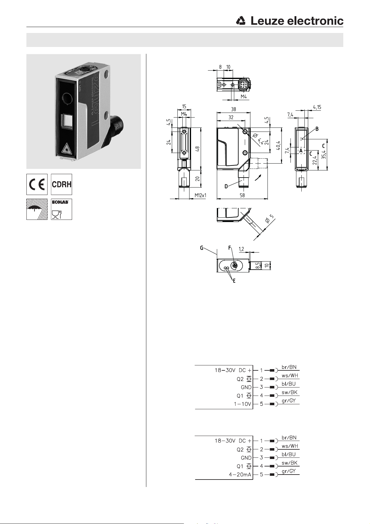
Dimensioned drawing
en 12-2017/11 50103922-03
20 … 500mm
Reflection-independent distance
information
Analog voltage output or current output
(can be inverted, teachable)
2 teachable switching outputs (push-pull)
M12 turning connector
Easy alignment through visible red light
Accessories:
(available separately)
Mounting systems
Cable with M12 connector
(KD …)
Control guard
A Receiver
B Transmitter
C Optical axis
D 90° turning connector
E LED yellow, green
F Operational control (rotary switch)
G Reference edge for the measurement (cover glass)
Electrical connection
We reserve the right to make changes • PAL_ODSL8_VC66_500_en_50103922_03.fm
Leuze electronic GmbH + Co. KG In der Braike 1 D-73277 Owen Tel. +49 (0) 7021 573-0
info@leuze.com • www.leuze.com
ODSL 8/V66-500-S12 - 12
ODSL 8/C66-500-S12 - 12
ODSL 8
Specifications
Optical data
Measurement range
Resolution
Light source laser
Laser class 2 acc. to IEC 60825-1:2007
Wavelength 650nm (visible red light)
Max. output power <1.2 mW
Pulse duration 4ms
Light spot 2x 6 mm
2)
Error limits (relative to measurement distance)
Absolute measurement accuracy
Repeatability
B/W detection thresh. (6 … 90% rem.) ≤ 1.5%
Temperature drift ≤ 0.2%/°C
Timing
Measurement time 2 … 7ms
Response time ≤ 20ms
Delay before start-up ≤ 300ms
Electrical data
Operating voltage U
Residual ripple ≤ 15 % of UB
Open-circuit current ≤ 50mA
Switching output/function
Signal voltage high/low ≥ (U
Analog output voltage 1 … 10V, RL≥ 2kW / current 4 … 20mA, RL< 500Ω
Indicators
Green LED continuous light ready
Yellow LED continuous light object within teach-in measurement distance (output Q1
Mechanical data
Housing metal
Optics cover glass
Weight 70g
Connection type M 12 connector, 5-pin, turning
Environmental data
Ambient temp. (operation/storage) -40°C … +50°C/-40°C … +70 °C
Protective circuit
VDE safety class
Protection class
Environmentally tested acc. to ECOLAB
Standards applied IEC 60947-5-2
1) Luminosity coefficient 6 % … 90 %, at 20 °C, measurement object ≥ 50x 50 mm²
2) Minimum and maximum value depend on measurement distance and configuration of the analog output
3) Same object, identical environmental conditions, measurement object ≥ 50x50 mm²
4) The push-pull switching outputs must not be connected in parallel
5) No display for output Q2
6) 2=polarity reversal protection, 3=short-circuit protection for all outputs
7) Rating voltage 250 VAC
8) In stop position of the turning connector (turning connector locked)
9) IP 69K test acc. to DIN 40050 part 9 simulated, high pressure cleaning conditions without the use of additives,
acids and bases are not part of the test
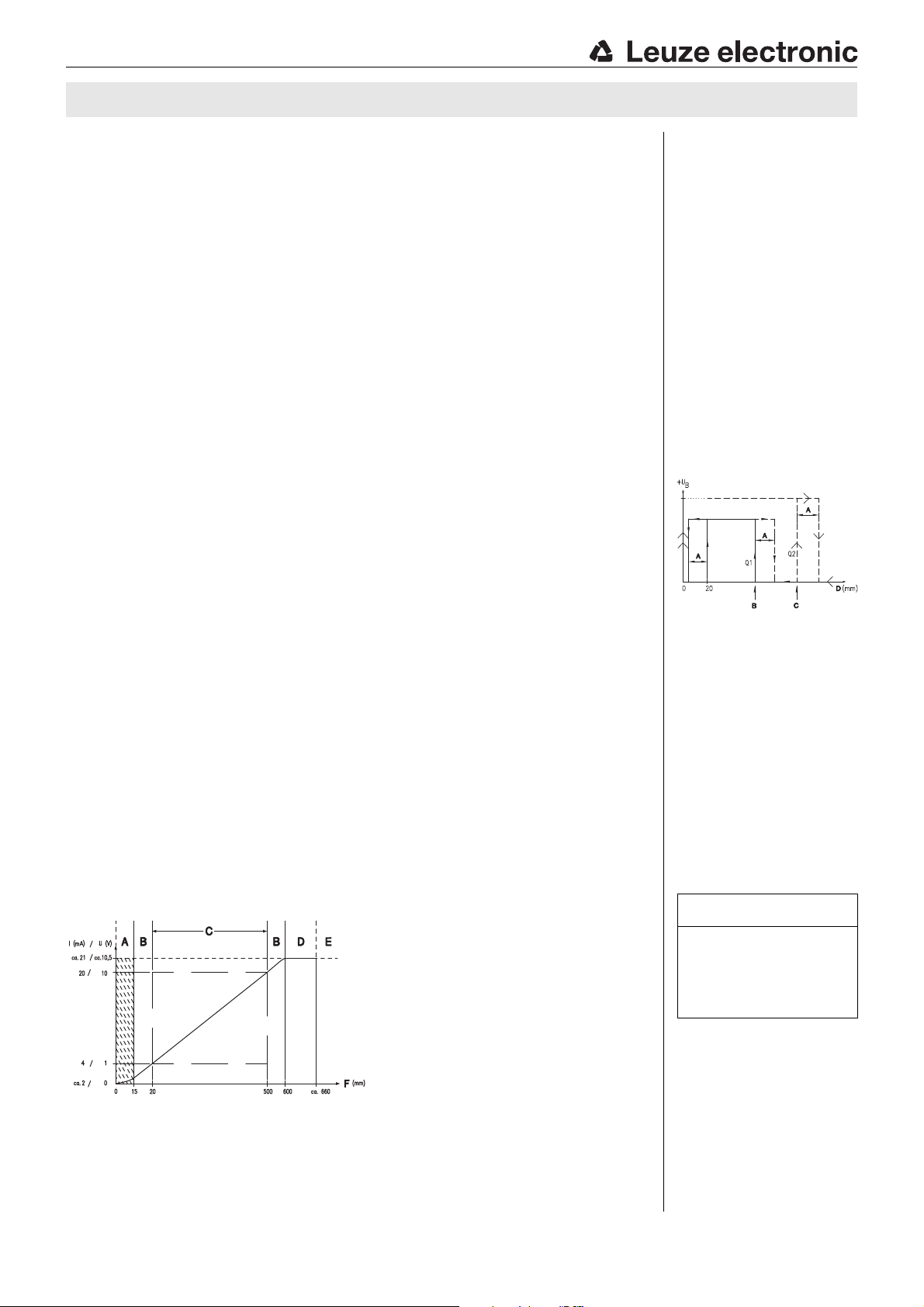
Characteristic curve of analog output:
1)
3)
B
4)
flashing (no teach) fault, teach values were not applied
off no voltage
flashing (no teach) teach values were not applied
off object outside teach-in measurement distance (output Q1
6)
7)
8)
20 … 500mm
0.1 … 0.5mm
2
at 500mm
1)
± 2% up to 200mm / ± 4 % 200 … 500 mm
± 1% up to 200mm / ± 3 % 200 … 500 mm
18 … 30VDC (incl. residual ripple)
2 push-pull switching outputs
pin 2: Q2, PNP light switching, NPN dark switching
pin 4: Q1, PNP light switching, NPN dark switching
-2 V)/≤ 2V
B
2, 3
II, all-insulated
IP 67, IP 69K
9)
A Area not defined
B Linearity not defined
C Measurement range
D Object present
E No object detected
F Measurement distance
Order guide
Designation Part no.
With M12 connector
and voltage output ODSL 8/V66-500-S12 50101879
and current output ODSL 8/C66-500-S12 50108361
Tables
Diagrams
Characteristic curve of switching
5)
)
4)
)
A Hysteresis
B Switching point Q1 (teach point)
C Switching point Q2 (teach point)
D Measurement distance
outputs:
Remarks
Operate in accordance with
intended use!
This product is not a safety sensor
and is not intended as personnel
protection.
The product may only be put into
operation by competent persons.
Only use the product in accor-
dance with the intended use.
Measurement time
depends on the reflectivity
of the measurement
object and on the
measurement mode.
ODSL 8/V66-500-S12 - 12 2017/11
ODSL 8/C66-500-S12 - 12

AVOID EXPOSURE – LASER RADIATION
IS EMITTED FROM THIS APERTURE
EXPOSITION DANGEREUSE – UN RAYONNEMENT
LASER EST ÉMIS PAR CETTE OUVERTURE
LASERSTRAHLUNG
NICHT IN DEN STRAHL BLICKEN
LASER KLASSE 2
DIN EN 60825-1:2008-05
Max. Leistung (peak):
Impulsdauer:
Wellenlänge:
RADIAZIONE LASER
NON FISSARE IL FASCIO
APARRECCHIO LASER DI CLASSE 2
EN 60825-1:2007
Potenza max. (peak):
Durata dell'impulso:
Lunghezza d'onda:
LASER RADIATION
DO NOT STARE INTO BEAM
CLASS 2 LASER PRODUCT
EN 60825-1:2007
Maximum Output (peak):
Pulse duration:
Wavelength:
RAYONNEMENT LASER
NE PAS REGARDER DANS LE FAISCEAU
APPAREIL À LASER DE CLASSE 2
EN 60825-1:2007
Puissance max. (crête):
Durée d`impulsion:
Longueur d`onde:
RADIACIÓN LÁSER
NO MIRAR FIJAMENTE AL HAZ
PRODUCTO LÁSER DE CLASE 2
EN 60825-1:2007
Potencia máx. (peak):
Duración del impulso:
Longitud de onda:
RADIAÇÃO LASER
NÃO OLHAR FIXAMENTE O FEIXE
EQUIPAMENTO LASER CLASSE 2
EN 60825-1:2007
Potência máx. (peak):
Período de pulso:
Comprimento de onda:
LASER RADIATION
DO NOT STARE INTO BEAM
CLASS 2 LASER PRODUCT
IEC 60825-1:2007
Complies with 21 CFR 1040.10
Maximum Output (peak):
Pulse duration:
Wavelength:
䉏⏘戟⺓
▎䦃展⏘㧮
伊䉏⏘ℶ❐
GB7247.1-2012
㦏⮶戢⒉᧤⽿⋋᧥
厘⑁㖐兼㢅梃
㽱栎
1,2 mW
4 ms
650 nm
1,2 mW
4 ms
650 nm
1.2 mW
4 ms
650 nm
1,2 mW
4
m
s
650 nm
1,2 mW
4 ms
650 nm
1,2 mW
4 ms
650 nm
1.2 mW
4 ms
650 nm
1.2 mW
4 ms
650 nm
50101928-03
A Laser exit opening
B Laser warning sign
A
B
ODSL 8 Optical laser distance sensors
Laser safety notices
ATTENTION, LASER RADIATION – LASER CLASS 2
Never look directly into the beam!
The device satisfies the requirements of IEC 60825-1:2007 (EN 60825-1:2007) safety regulations for a product in laser class 2 as well
as the U.S. 21 CFR 1040.10 regulations with deviations corresponding to "Laser Notice No. 50" from June 24th, 2007.
Never look directly into the laser beam or in the direction of reflecting laser beams!
If you look into the beam path over a longer time period, there is a risk of injury to the retina.
Do not point the laser beam of the device at persons!
Intercept the laser beam with an opaque, non-reflective object if the laser beam is accidentally directed towards a person.
When mounting and aligning the device, avoid reflections of the laser beam off reflective surfaces!
CAUTION! Use of controls or adjustments or performance of procedures other than specified herein may result in hazardous light
exposure.
Adhere to the applicable legal and local regulations regarding protection from laser beams.
The device must not be tampered with and must not be changed in any way.
There are no user-serviceable parts inside the device.
Repairs must only be performed by Leuze electronic GmbH + Co. KG.
NOTICE
Affix laser information and warning signs!
Laser information and warning signs are affixed to the device (see
(stick-on labels) are supplied in several languages (see
).
Affix the laser information sheet with the language appropriate for the place of use to the device.
When using the device in the US, use the stick-on label with the "Complies with 21 CFR 1040.10" notice.
Affix the laser information and warning signs near the device if no signs are attached to the device (e.g. because the device is too
small) or if the attached laser information and warning signs are concealed due to the installation position.
Affix the laser information and warning signs so that they are legible without exposing the reader to the laser radiation of the device
or other optical radiation.
). In addition, self-adhesive laser information and warning signs
Leuze electronic GmbH + Co. KG In der Braike 1 D-73277 Owen Tel. +49 (0) 7021 573-0 ODSL 8/V66-500-S12 - 12
info@leuze.com • www.leuze.com ODSL 8/C66-500-S12 - 12

Preferred movement of the objects Preferred mounting in connection to objects with structured surface
View through a chase
If the ODSL 8 has to be installed behind a cover, the chase has to
have at least the size of the optical glass cover. Otherwise, a correct
measurement is not possible or can not be guaranteed.
Alignment to measurement objects with reflecting surfaces
If the measurement object to be detected has a reflecting surface, a measurement
may not be possible depending on the angle in which the light is reflected by the
measurement object's surface. Adjust the angle between the sensor and the measure-
ment object such that the sensor can reliably detect the measurement object.
ODSL 8
Installation instructions
Mounting systems are available which have to be ordered separately at Leuze electronic. Apart from this, the drilled-through holes and
threaded holes are suitable for the individual mounting of the ODSL 8, depending on the area in which it is used. When mounting, avoid
application of excessive force on the housing.
ODSL 8/V66-500-S12 - 12 2017/11
ODSL 8/C66-500-S12 - 12

ODSL 8 Optical laser distance sensors
TI teach-in with rotary switch
1.Position measurement object at the desired measurement distance ().
2.Turn rotary switch into the desired position (Low, High, 1, 2) ().
Wait for optical confirmation by flashing of the LEDs.
Teach function Rotary switch position Green LED Yellow LED
Analog output 1 V/4 mA low On Flashes
Analog output 10 V/20 mA high Flashes On
Switching output Q1 1 Flash synchronously
Switching output Q2 2 Flash alternatingly
3.For teaching, position rotary switch onto "Run" ().
Wait for optical confirmation by end of flashing signal (green LED on).
Reset of the analog output to factory settings
Reset 1V/4mA analog output at 20mm:
1.Position measurement object just below start of measurement range (20mm).
2.Position rotary switch on "Low". Wait for optical confirmation by flashing of the LEDs.
3.For teaching, position rotary switch onto "Run".
Wait for optical confirmation by end of flashing signal (green LED on).
Reset 10V/20mA analog output at 500mm:
1.Position measurement object just beyond end of measurement range (500mm).
2.Position rotary switch on "High". Wait for optical confirmation by flashing of the LEDs.
3.For teaching, position rotary switch onto "Run".
Wait for optical confirmation by end of flashing signal (green LED on).
Error messages
Continuously flashing LEDs in switch position "Run" signal an unsuccessful teach event (sensor not ready):
Green LED Yellow LED Error
Oon Flashes Teach 1V/4 mA analog output unsuccessful
Flashes On Teach 10V/20mA analog output unsuccessful
Flash synchronously Teach switching output Q1 unsuccessful
Flash alternatingly Teach switching output Q1 unsuccessful
Remedy:
Repeat teach event or
Disconnect sensor from voltage to restore the old values.
Leuze electronic GmbH + Co. KG In der Braike 1 D-73277 Owen Tel. +49 (0) 7021 573-0 ODSL 8/V66-500-S12 - 12
info@leuze.com • www.leuze.com ODSL 8/C66-500-S12 - 12

ODSL 8
ODSL 8/V66-500-S12 - 12 2017/11
ODSL 8/C66-500-S12 - 12
 Loading...