

Page 1
Original operating instructions
ODS 9
Laser distance sensor
We reserve the right to make technical changes
EN • 2020-07-31 • 50138237
Page 2

© 2020
Leuze electronic GmbH + Co. KG
Leuze electronic GmbH + Co. KG ODS 9 2
Page 3

Table of contents
1 About this document ............................................................................................6
1.1 Used symbols and signal words .............................................................................................6
1.2 Important terms....................................................................................................................... 8
2 Safety .....................................................................................................................9
2.1 Intended use ........................................................................................................................... 9
2.2 Foreseeable misuse ............................................................................................................... 9
2.3 Competent persons .............................................................................................................. 10
2.4 Disclaimer ............................................................................................................................. 10
2.5 Laser safety notices.............................................................................................................. 11
3 Device description ..............................................................................................14
3.1 Device overview.................................................................................................................... 14
3.1.1 General information...........................................................................................................14
3.1.2 Operating principle ............................................................................................................15
3.1.3 Performance characteristics.............................................................................................. 15
3.1.4 Accessories .......................................................................................................................15
3.2 Connection technology .........................................................................................................16
3.3 Indicators and operational controls....................................................................................... 16
3.3.1 LED indicators ...................................................................................................................16
3.3.2 Control buttons ..................................................................................................................16
3.3.3 Display............................................................................................................................... 17
3.3.4 Meaning of the display icons .............................................................................................19
3.4 Configuration / menu structure ............................................................................................. 19
3.4.1 Input menu ........................................................................................................................20
3.4.2 Output_SSC1 menu ..........................................................................................................20
3.4.3 Output_SSC2 menu ..........................................................................................................21
3.4.4 Analog_Output menu ........................................................................................................23
3.4.5 Serial Menu .......................................................................................................................23
3.4.6 Application menu...............................................................................................................25
3.4.7 Settings menu ...................................................................................................................30
3.4.8 Ending configuration.......................................................................................................... 31
3.5 Configuration example.......................................................................................................... 31
Table of contents
4 Applications ........................................................................................................34
4.1 Wood width measurement .................................................................................................... 34
4.2 Assembly inspection ............................................................................................................. 35
5 Mounting..............................................................................................................36
5.1 Mounting with mounting system ........................................................................................... 36
6 Electrical connection..........................................................................................37
6.1 Overview............................................................................................................................... 37
6.2 Pin assignment .....................................................................................................................37
7 Starting up the device ........................................................................................40
7.1 Teaching and configuring output functions ........................................................................... 40
7.1.1 Setting the analog output ..................................................................................................40
7.1.2 Setting the switching outputs............................................................................................. 41
7.1.3 Teach-in / teach................................................................................................................. 46
7.1.4 Teaching the output functions via the multifunction input.................................................. 46
7.1.5 Teaching the output functions via the IO-Link system commands ....................................48
7.2 Setting measurement value processing and filtering ............................................................ 50
7.3 Reset to factory settings .......................................................................................................50
Leuze electronic GmbH + Co. KG ODS 9 3
Page 4

Table of contents
7.4 IO-Link interface ................................................................................................................... 50
7.4.1 Overview ...........................................................................................................................50
7.4.2 IO-Link process data .........................................................................................................52
7.5 Serial interface...................................................................................................................... 53
7.5.1 Measurement value output for various transmission types ............................................... 53
7.5.2 Commands for remote control operation........................................................................... 55
7.5.3 Termination of data lines ...................................................................................................57
7.5.4 Operation on the fieldbus and Ethernet............................................................................. 58
8 Connecting to a PC – SensorStudio ................................................................59
8.1 System requirements............................................................................................................ 60
8.2 Installing SensorStudio configuration software and IO-Link USB master............................ 60
8.2.1 Downloading configuration software .................................................................................60
8.2.2 Installing the SensorStudio FDT frame ............................................................................61
8.2.3 Installing drivers for IO-Link USB master ..........................................................................61
8.2.4 Connecting IO-Link USB master to the PC .......................................................................62
8.2.5 Connecting IO-Link USB master to the sensor .................................................................62
8.2.6 Installing the DTM and IODD ............................................................................................63
8.2.7 Importing device descriptions............................................................................................ 63
8.3 Starting the SensorStudio configuration software................................................................ 63
8.4 Short description of the SensorStudio configuration software ............................................. 65
8.4.1 FDT frame menu ...............................................................................................................66
8.4.2 IDENTIFICATION function ................................................................................................66
8.4.3 CONFIGURATION function............................................................................................... 67
8.4.4 PROCESS function ...........................................................................................................69
8.4.5 DIAGNOSIS function.........................................................................................................71
8.4.6 Exiting SensorStudio ........................................................................................................71
9 Troubleshooting..................................................................................................72
9.1 What to do in case of failure? ...............................................................................................72
9.2 LED indicators ...................................................................................................................... 72
9.3 Indicators in the display ........................................................................................................72
10 Care, maintenance and disposal .......................................................................73
10.1 Cleaning................................................................................................................................ 73
10.2 Servicing ............................................................................................................................... 73
10.3 Disposing .............................................................................................................................. 73
11 Service and support ...........................................................................................74
11.1 What to do should servicing be required? ............................................................................ 74
12 Technical data .....................................................................................................75
12.1 Measurement data................................................................................................................ 75
12.2 Optical data........................................................................................................................... 77
12.3 Indicators and operational controls....................................................................................... 78
12.4 Electrical data .......................................................................................................................78
12.5 Mechanical data.................................................................................................................... 78
12.6 Environmental data............................................................................................................... 79
12.7 Dimensioned drawings ......................................................................................................... 80
12.8 Dimensioned drawings: Accessories .................................................................................... 81
13 Order guide and accessories.............................................................................82
13.1 Type overview ODS9........................................................................................................... 82
13.2 Accessories – cables and connectors .................................................................................. 83
Leuze electronic GmbH + Co. KG ODS 9 4
Page 5

Table of contents
13.3 Other accessories................................................................................................................. 84
13.3.1 Accessories – PC connection............................................................................................ 84
13.3.2 Accessories – IO-Link master ...........................................................................................84
14 EC Declaration of Conformity ............................................................................85
Leuze electronic GmbH + Co. KG ODS 9 5
Page 6

About this document
1 About this document
1.1 Used symbols and signal words
Tab.1.1: Warning symbols and signal words
Symbol indicating dangers to persons
Symbol indicating dangers from harmful laser radiation
NOTE Signal word for property damage
Indicates dangers that may result in property damage if the measures for danger avoidance are not followed.
CAUTION Signal word for minor injuries
Indicates dangers that may result in minor injury if the measures for danger
avoidance are not followed.
Tab.1.2: Other symbols
Symbol for tips
Text passages with this symbol provide you with further information.
Symbol for action steps
Text passages with this symbol instruct you to perform actions.
Leuze electronic GmbH + Co. KG ODS 9 6
Page 7

About this document
Tab.1.3: Terms and abbreviations
BG Background
DS Data Storage
DSUpload Data Storage Upload
DTM Device Type Manager
FDT Field Device Tool
FE Functional earth
IODD IODevice Description
Mode in which switching outputs react/switch when an object enters a set distance
Data memory of the connected IO-Link master
Upload to the data memory of the connected IO-Link master
Software device manager of the sensor
Software frame for management of device managers (DTM)
File with information on process data and device parameters
Max.
Min.
Maximum
Minimum
NEC National Electric Code
ODS Optical Distance Sensor
Optical distance sensor
OLED Organic Light Emitting Diode
Organic LED
PELV Protective Extra Low Voltage
Protective extra low voltage with reliable disconnection
Pt Point
Switching point
SIO Standard IO mode
Signal transfer without IO-Link
SP Setpoint
Position at which the switching point is set
SSC Switching Signal Channel
Abbreviation for the switching outputs acc. to Smart Sensor Profile
SSP Smart Sensor Profile
Profile acc. to IO-Link standard
UL Underwriters Laboratories
Leuze electronic GmbH + Co. KG ODS 9 7
Page 8

About this document
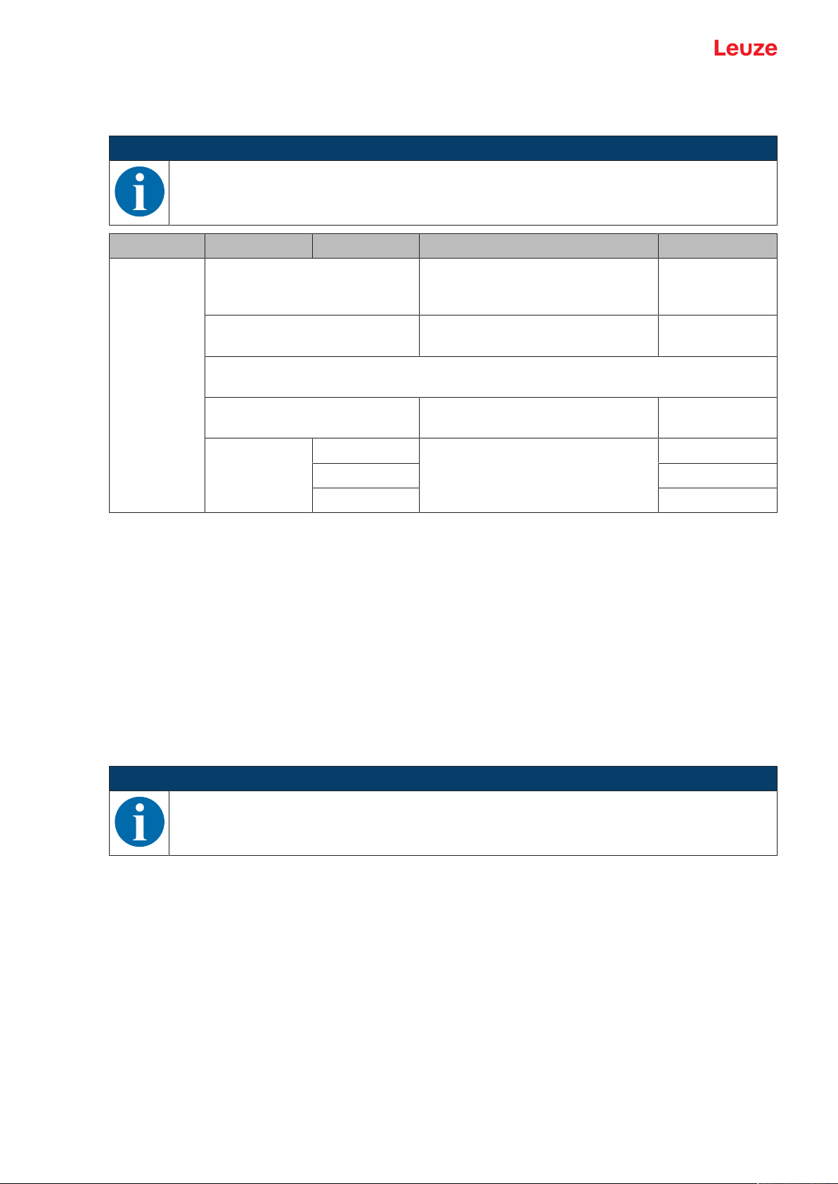
1.2 Important terms
Tab.1.4: Important terms
Response time
(Response time)
Also integration time or measurement time. Maximum length of time from
the occurrence of an erratic change in distance to the steady state of the
measurement value.
The response time depends on the set average calculation. Although the
average calculation increases the response time, it also improves reproducibility.
Resolution Smallest representable change in measurement value, distance and
speed.
Warmup time Time the sensor needs in order to reach the operating temperature. An op-
timal measurement is only possible after the end of the warmup time.
The warmup time is approximately 20minutes.
Output resolution The output resolution describes how the measurement values are pre-
sented on the display and digital interfaces.
Depending on the device model, the output resolution of the ODS9 is
0.01mm or 0.1mm and cannot be changed.
Output time
Time interval of measurement value updating at the interface.
(Output time)
Readiness delay The delay before start-up indicates the point in time when the first valid
measurement can be obtained after switching on.
Data storage
Data memory of the connected IO-Link master.
IO-Link data storage
DSUpload Data Storage Upload.
Upload to the data memory of the connected IO-Link master.
Accuracy Maximum expected deviation of the measurement value between the de-
termined and real distance value within the specified measurement range.
Light switching
Dark switching
The behavior of the switching output if an object is within the taught/configured switching distance.
• Light switching: switching output active (high)
• Dark switching: switching output not active (low)
Diffuse reflection Return and/or degree of reflection of the radiated light. Observe the specifi-
cations regarding diffuse reflection (see chapter 12 "Technical data").
• 90% is white
• 6% is black
Reproducibility Also repeatability. Deviation of multiple measurement results relative to
each other under identical conditions. Dependent on the measurement distance and the diffuse reflection of the measurement object.
The reproducibility can be considered as the measure of measurement
value noise and is affected by the configuration of the response time.
Triangulation measurement
principle
Distance measuring procedure, which determines the distance of an object
by the incidence angle of the light reflected from the object.
Leuze electronic GmbH + Co. KG ODS 9 8
Page 9
Safety
2 Safety
This sensor was developed, manufactured and tested in line with the applicable safety standards. It corresponds to the state of the art.
2.1 Intended use
The device is designed as an optoelectronic sensor for the optical, contactless measurement of the distance to objects.
Areas of application
The laser distance sensor is designed for the following areas of application:
• Distance measurement
• Thickness measurement
• Positioning
• Diameter determination
• Fill level indicator
Observe intended use!
The protection of personnel and the device cannot be guaranteed if the device is operated in a
manner not complying with its intended use.
Ä Only operate the device in accordance with its intended use.
Ä LeuzeelectronicGmbH+Co.KG is not liable for damages caused by improper use.
Ä Read these operating instructions before commissioning the device. Knowledge of the oper-
CAUTION
ating instructions is an element of proper use.
CAUTION
UL applications!
For UL applications, use is only permitted in Class 2 circuits in accordance with the NEC (National Electric Code).
NOTICE
Comply with conditions and regulations!
Ä Observe the locally applicable legal regulations and the rules of the employer's liability insur-
ance association.
2.2 Foreseeable misuse
Any use other than that defined under "Intended use" or which goes beyond that use is considered improper use.
In particular, use of the device is not permitted in the following cases:
• in rooms with explosive atmospheres
• in circuits which are relevant to safety
• for medical purposes
NOTICE
Do not modify or otherwise interfere with the device!
Ä Do not carry out modifications or otherwise interfere with the device. The device must not be
tampered with and must not be changed in any way.
Ä The device must not be opened. There are no user-serviceable parts inside.
Ä Repairs must only be performed by Leuze electronic GmbH + Co. KG.
Leuze electronic GmbH + Co. KG ODS 9 9
Page 10

Safety
2.3 Competent persons
Connection, mounting, commissioning and adjustment of the device must only be carried out by competent
persons.
Prerequisites for competent persons:
• They have a suitable technical education.
• They are familiar with the rules and regulations for occupational safety and safety at work.
• They are familiar with the original operating instructions of the device.
• They have been instructed by the responsible person on the mounting and operation of the device.
Certified electricians
Electrical work must be carried out by a certified electrician.
Due to their technical training, knowledge and experience as well as their familiarity with relevant standards
and regulations, certified electricians are able to perform work on electrical systems and independently detect possible dangers.
In Germany, certified electricians must fulfill the requirements of accident-prevention regulations DGUV
(German Social Accident Insurance) provision 3 (e.g. electrician foreman). In other countries, there are respective regulations that must be observed.
2.4 Disclaimer
LeuzeelectronicGmbH+Co.KG is not liable in the following cases:
• The device is not being used properly.
• Reasonably foreseeable misuse is not taken into account.
• Mounting and electrical connection are not properly performed.
• Changes (e.g., constructional) are made to the device.
Leuze electronic GmbH + Co. KG ODS 9 10
Page 11
Safety
2.5 Laser safety notices
Laser class 1 (ODS9L1...)
ATTENTION
LASER RADIATION – CLASS 1 LASER PRODUCT
The device satisfies the requirements of IEC/EN 60825-1:2014 safety regulations for a product
of laser class1 and complies with 21 CFR 1040.10 except for conformance with IEC 60825-1
Ed. 3., as described in Laser Notice No. 56, dated May 8, 2019.
Ä Observe the applicable statutory and local laser protection regulations.
Ä The device must not be tampered with and must not be changed in any way.
There are no user-serviceable parts inside the device.
Repairs must only be performed by Leuze electronic GmbH + Co. KG.
Laser class 2 (ODS9L2...)
ATTENTION
LASER RADIATION – CLASS 2 LASER PRODUCT
Do not stare into beam!
The device satisfies the requirements of IEC/EN 60825-1:2014 safety regulations for a product
of laser class 2 and complies with 21 CFR 1040.10 except for conformance with IEC 60825-1
Ed. 3., as described in Laser Notice No. 56, dated May 8, 2019.
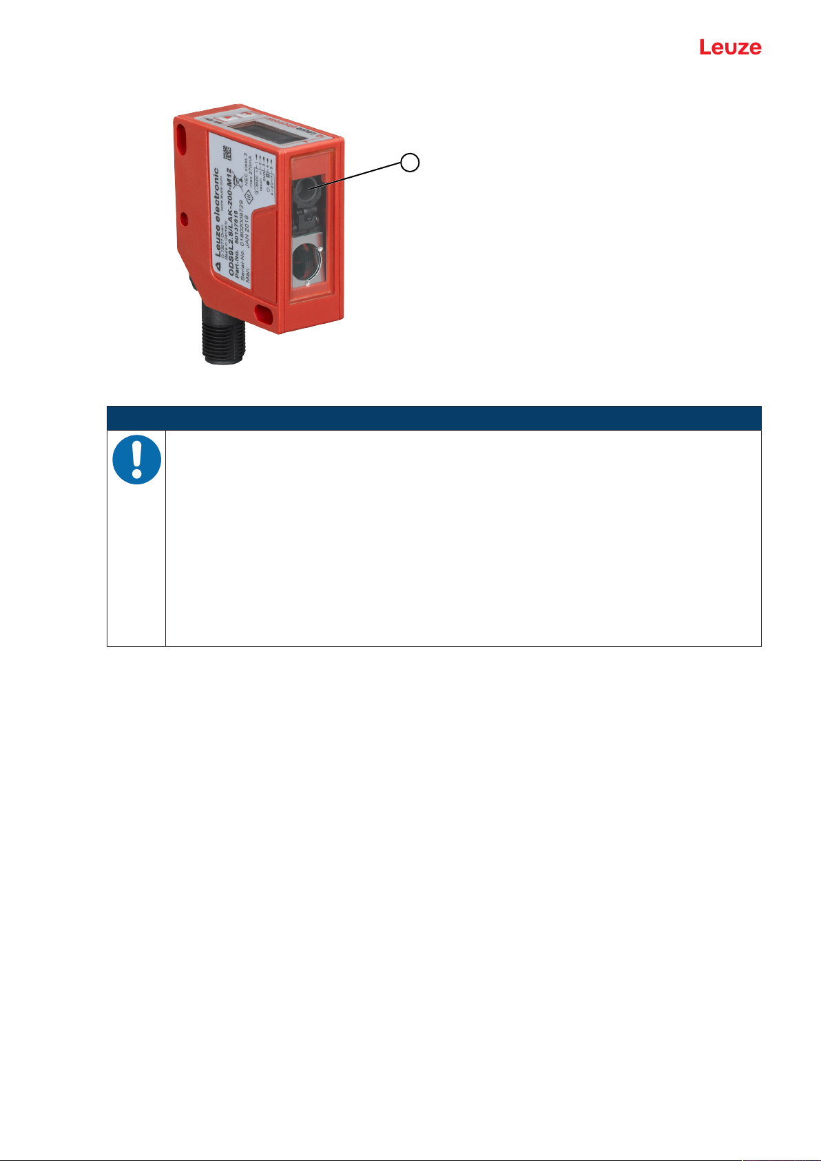
Ä Never look directly into the laser beam, the laser aperture(1) or in the direction of reflected
laser beams! If you look into the beam path over a longer time period, there is a risk of injury
to the retina.
Ä Do not point the laser beam of the device at persons!
Ä Interrupt the laser beam using a non-transparent, non-reflective object if the laser beam is
accidentally directed towards a person.
Ä When mounting and aligning the device, avoid reflections of the laser beam off reflective
surfaces!
Ä CAUTION! Use of controls or adjustments or performance of procedures other than speci-
fied herein may result in hazardous light exposure.
Ä Observe the applicable statutory and local laser protection regulations.
Ä The device must not be tampered with and must not be changed in any way.
There are no user-serviceable parts inside the device.
Ä Repairs must only be performed by Leuze electronic GmbH + Co. KG.
Ä The laser radiation emitted from the sensor is collimated. The laser is operated in pulse
mode. Pulse power, pulse duration and wavelength see chapter 12 "Technical data".
Leuze electronic GmbH + Co. KG ODS 9 11
Page 12
Safety
1
Fig.2.1: Laser aperture
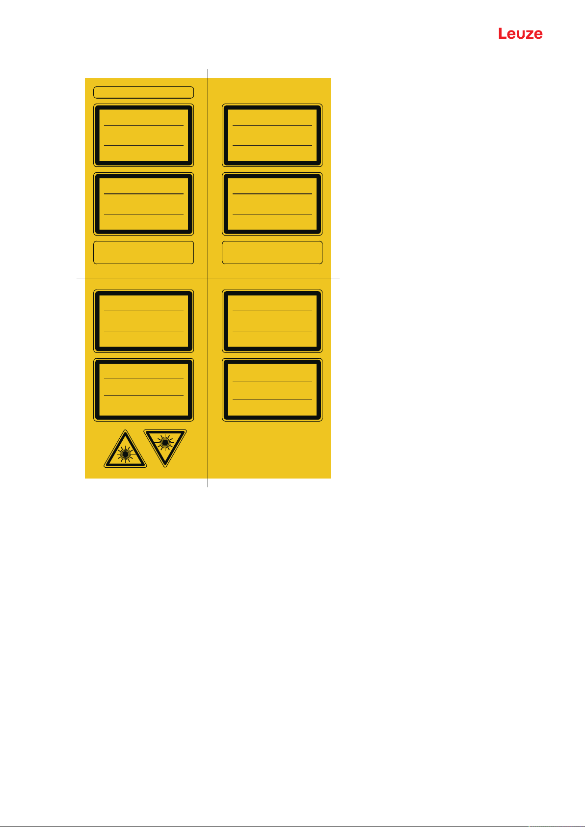
NOTICE
Affix laser information and warning signs!
Laser information and warning signs attached to the device. Also included with the device are
self-adhesive laser warning and laser information signs (stick-on labels) in multiple languages.
Ä Affix the laser information sheet to the device in the language appropriate for the place of
use.
When using the device in the US, use the stick-on label with the "Complies with
21CFR1040.10" notice.
Ä Affix the laser information and warning signs near the device if no signs are attached to the
device (e.g. because the device is too small) or if the attached laser information and warning
signs are concealed due to the installation position.
Affix the laser information and warning signs so that they are legible without exposing the
reader to the laser radiation of the device or other optical radiation.
Leuze electronic GmbH + Co. KG ODS 9 12
Page 13
Safety
LASERSTRAHLUNG
NICHT IN DEN STRAHL BLICKEN
LASER KLASSE 2
EN 60825-1:2014
Max. Leistung (peak):
Impulsdauer:
Wellenlänge:
RADIAZIONE LASER
NON FISSARE IL FASCIO
APARRECCHIO LASER DI CLASSE 2
EN 60825-1:2014
Potenza max. (peak):
Durata dell'impulso:
Lunghezza d'onda:
LASER RADIATION
DO NOT STARE INTO BEAM
CLASS 2 LASER PRODUCT
EN 60825-1:2014
Maximum Output (peak):
Pulse duration:
Wavelength:
RAYONNEMENT LASER
NE PAS REGARDER DANS LE FAISCEAU
APPAREIL À LASER DE CLASSE 2
EN 60825-1:2014
Puissance max. (crête):
Durée d`impulsion:
Longueur d`onde:
RADIACIÓN LÁSER
NO MIRAR FIJAMENTE AL HAZ
PRODUCTO LÁSER DE CLASE 2
EN 60825-1:2014
Potencia máx. (peak):
Duración del impulso:
Longitud de onda:
RADIAÇÃO LASER
NÃO OLHAR FIXAMENTE O FEIXE
EQUIPAMENTO LASER CLASSE 2
EN 60825-1:2014
Potência máx. (peak):
Período de pulso:
Comprimento de onda:
LASER RADIATION
DO NOT STARE INTO BEAM
CLASS 2 LASER PRODUCT
IEC 60825-1:2014
Complies with 21 CFR 1040.10
Maximum Output (peak):
Pulse duration:
Wavelength:
激光辐射
勿直视光束
2 类激光产品
IEC 60825-1:2014
最大输出(峰值):
脉冲持续时间:
波长:
1,8 mW
22 ms
650 nm
1,8 mW
22 ms
650 nm
1.8 mW
22 ms
650 nm
1,8 mW
22
m
s
650 nm
1,8 mW
22 ms
650 nm
1,8 mW
22 ms
650 nm
1.8 mW
22 ms
650 nm
1.8 mW
22 ms
650 nm
50106507-06
Fig.2.2: Laser information and warning signs
Leuze electronic GmbH + Co. KG ODS 9 13
Page 14
Device description
1
2
3
4
5
6
7
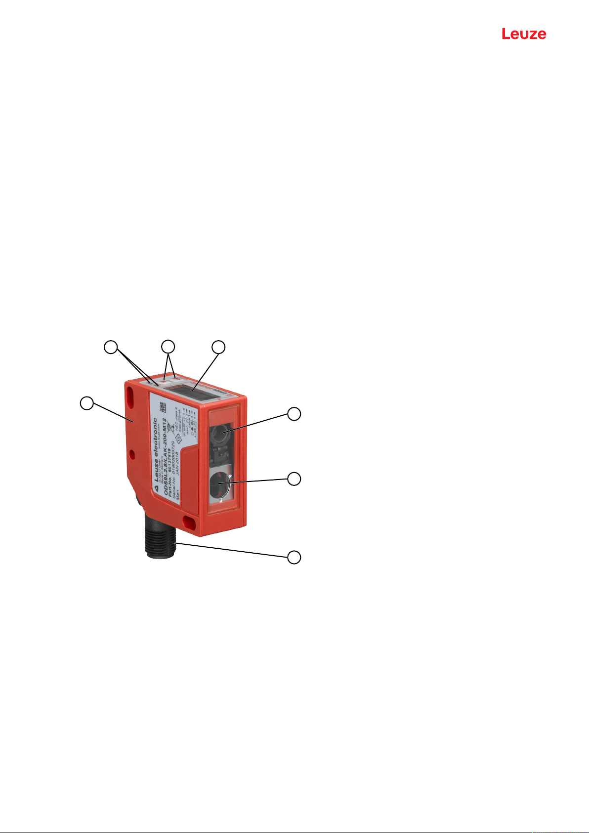
3 Device description
3.1 Device overview
3.1.1
General information
The laser distance sensor is an optical distance sensor that operates according to the triangulation measurement principle.
The sensor consists of the following components:
• Transmitter: laser spot
• Receiver
• White OLED display
• Control panel with control buttons
• Status LEDs
• Connection for connecting to the control: M12 connector
The sensor can be configured using display and control buttons.
With the SensorStudio configuration software, the sensors can be configured via the IO-Link interface with
a PC and the measurement values visualized. Stored parameter sets can be duplicated in other sensors.
The connection is made via the IO-Link USB master, which is available as an accessory.
1 Device housing
2 Status LEDs
3 Control buttons
4 Display
5 Transmitter
6 Receiver
7 Connection
Fig.3.1: Device construction
Leuze electronic GmbH + Co. KG ODS 9 14
Page 15

Device description
3.1.2
3.1.3
Operating principle
Triangulation measurement principle
Distance measuring procedure, which determines the distance of an object by the incidence angle of the
light reflected from the object.
Advantages of the triangulation measurement principle:
• Short response times and, thus, high measurement rates
• High accuracy
Performance characteristics
The most important performance characteristic of the ODS9 laser distance sensor:
• Measurement ranges:
50mm…650mm against objects (6…9% diffuse reflection)
• Analog current and voltage output (configurable)
Factory setting: current output
• OLED display and control buttons for configuration
• Configurable measurement range and measure mode
• Measurement value display in mm on OLED display
• IO-Link version 1.1
• Compliant with the "Smart Sensor Profile" specification
• Dual Channel: the IO-Link interface can be used in parallel with the other output functions.
• Communication interface RS232/RS485, depending on the device type
• Optional: multifunction input for deactivating the laser or for teaching the digital switching points (teachin)
Factory setting: input for deactivating the laser
• Optional: second switching output if the IO-Link interface is not used
For measurement against objects:
• Measurement range: 50mm…max. 650mm, dependent on device type
• Measurement against diffusely reflective objects
• Reflection-independent distance information
• Applications:
• Distance measurement
• Contour determination
• Thickness measurement
• Positioning
• Diameter determination
• Sag determination
• Stack height measurement
• Loop measurement
3.1.4
Accessories
Special accessories are available for the laser distance sensor (see chapter 13 "Order guide and accessories"):
• Mounting systems for mounting on rods
• Connection cables
• IO-Link USB master set for connecting to a PC
• IO-Link master for cascading or integrating in a higher-level network
Leuze electronic GmbH + Co. KG ODS 9 15
Page 16
Device description
2 31
4
3.2 Connection technology
For the electrical connection of the laser distance sensor, the following connection variants are available:
• M12 connector, 5-pin, turns 180°
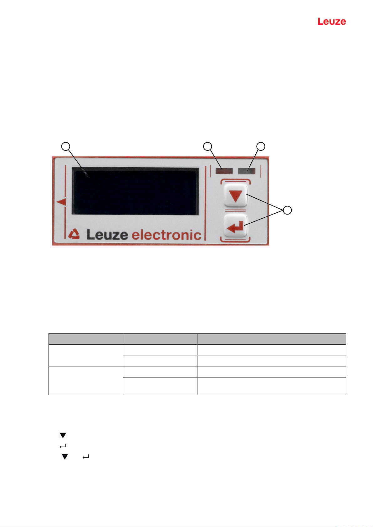
3.3 Indicators and operational controls
The device housing is provided with the following indicators and operational controls:
• OLED display
• Two control buttons
• Green LED: operating state (PWR)
• Orange LED: switching output information (SSC)
3.3.1
3.3.2
1 Display
2 Orange LED (SSC1/SSC2)
3 Green LED (PWR)
4 Control buttons
Fig.3.2: Indicators and operational controls
LED indicators
Tab.3.1: Meaning of the LED indicators on the device housing
LED Color, state Description
Green LED
PWR
Orange LED
Switching outputSSC1/
Green Sensor ready
Off No supply voltage
On Object detected in the switching range
Off No object detected in the switching range
SSC2
Control buttons
The sensor can be configured using display and control buttons. The display is controlled via the control
buttons. You can make adjustments in the application via the control buttons.
• – Scroll through the functions
• – Enter button: select function, confirm/enter value
The and buttons have different functions depending on the operating situation. These functions are
displayed via icons at the right edge of the display (see chapter 3.3.4 "Meaning of the display icons").
Leuze electronic GmbH + Co. KG ODS 9 16
Page 17
Device description
Navigating within the menus
Use the navigation button to move through the menu.
Activate the desired selection with the enter button .
The number of bars at the left edge of the display indicates the current menu level.
Selecting options
Set the desired option with the navigation button and the enter button .
Resetting to factory settings
Ä While switching on the supply voltage, press the enter button to reset the sensor configuration to the
factory settings.
Ä Press the enter button again to reset all parameters to factory settings. All parameter settings made
previously are permanently lost.
Press the navigation button to return to process mode without resetting the parameters.
NOTICE
You can also use the menu (see chapter 3.4 "Configuration / menu structure") or the SensorStudio configuration software to reset to factory settings (see chapter 8 "Connecting to a PC
– SensorStudio").
3.3.3
Display
The display changes depending on the current operating mode. The following display modes exist:
• Menu display
Press one of the two control buttons once or twice to access the menu display.
For information on operating via the menu, see chapter 3.4 "Configuration / menu structure" and the
configuration example (see chapter 3.5 "Configuration example").
• Process mode
After switching on the supply voltage and error-free initialization of the device, the green LED lights up
continuously. The laser distance sensor is in process mode.
In process mode, the current measurement value is displayed in the display, e.g. "267 mm".
NOTICE
In the menu display, the selectable or editable values are shown with inverted text colors (black
on white background).
If no key is pressed for approx. 6 minutes in the configuration menu, the device automatically returns to the process mode.
The sensor can be protected against unauthorized configuration change by activating the password query (see chapter 3.4.7 "Settings menu"). The password is permanently set to 165. In addition, a complete button lock can be activated using the lock function (device access locks,
bit2) (see the table "Status displays on the display").
Leuze electronic GmbH + Co. KG ODS 9 17
Page 18
Device description
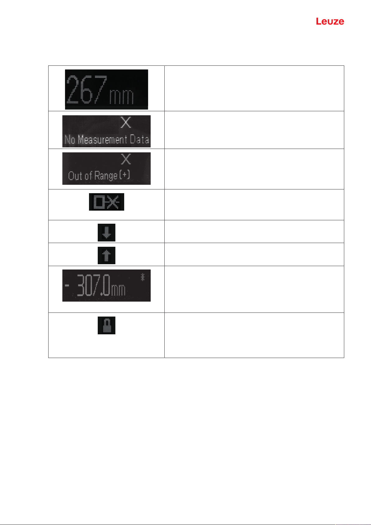
Status displays in process mode
Tab.3.2: Status displays on the display
Object distance in mm
No measurement value available, e.g. due to a weak or missing
reception signal.
No object detected or reception signal too weak.
No object detected or reception signal too weak.
• Out of Range (+)
• Out of Range (-)
• +max
Sensor deactivated, laser switched off
• Via the input function (see chapter 3.4.1 "Input menu")
• Via the IO-Link command
The current measurement value is less than the lower limit
value of the analog output distance.
The current measurement value is greater than the upper limit
value of the analog output distance.
The measurement value has an offset and/or the gradient is
falling (-1)
Lock function: Button lock activated via IO-Link (device access
locks, bit3)
The button lock can also be enabled and set using the configuration software SensorStudio:
Configuration > Local operation
Leuze electronic GmbH + Co. KG ODS 9 18
Page 19
Device description
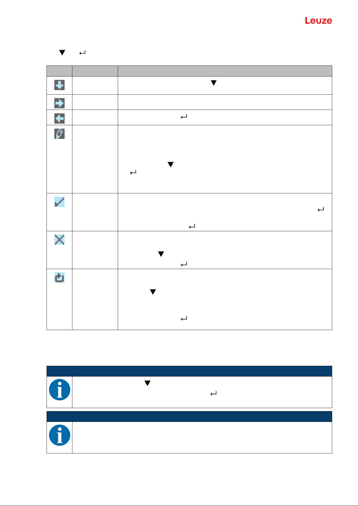
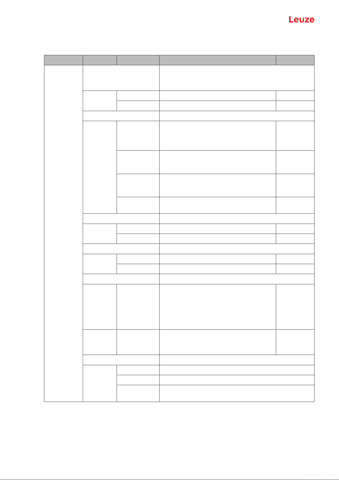
3.3.4
Meaning of the display icons
The and buttons have different functions depending on the operating situation. These functions are
displayed via icons at the right edge of the display.
Icon Position Function
First line
By pressing the navigation button you select the next parameter within a
menu level.
Second line Symbolizes the respective, next menu level that you have not yet selected.
Second line
Press the enter button to exit the menu level or the menu.
Second line Symbolizes the input mode.
The selected (highlighted) option field can be a fixed selection parameter or a
multi-digit input field.
With a multi-digit input field, you can change the active digit cyclically using the
navigation button and switch from one digit to the next using the enter button .
Note: If this icon does not appear, the local configuration lock is set via IO-Link
(index: 12, bit 2).
Second line Confirmation of the selection.
This icon appears when you complete an option field with theenterbutton
and the previously entered value is valid.
Pressing the enter button again saves and displays the change locally.
Second line Reject the selection.
This icon is accessed from the previous icon (check mark) by pressing thenavigationbutton .
Press the enter button to reject the current value or option parameter.
Second line Return to selection.
This icon is accessed from the previous icon (cross) by pressing thenavigationbutton .
This icon is also accessed if the value newly entered previously is outside the
permissible value range, making correction of the entry necessary.
Press the enter button to reset the current value or option parameter and
enter a new value or select a new option parameter.
3.4 Configuration / menu structure
The following chapters show the structure of all menu items. For each sensor model, only the actually available menu items are present for entering values or for selecting settings.
NOTICE
Use the navigation button to move through the menu.
Activate the desired selection with the enter button .
NOTICE
The number of bars at the left edge of the display indicates the current menu level.
For information on the meaning of the display icons, see chapter 3.3.4 "Meaning of the display
icons".
Leuze electronic GmbH + Co. KG ODS 9 19
Page 20
Device description
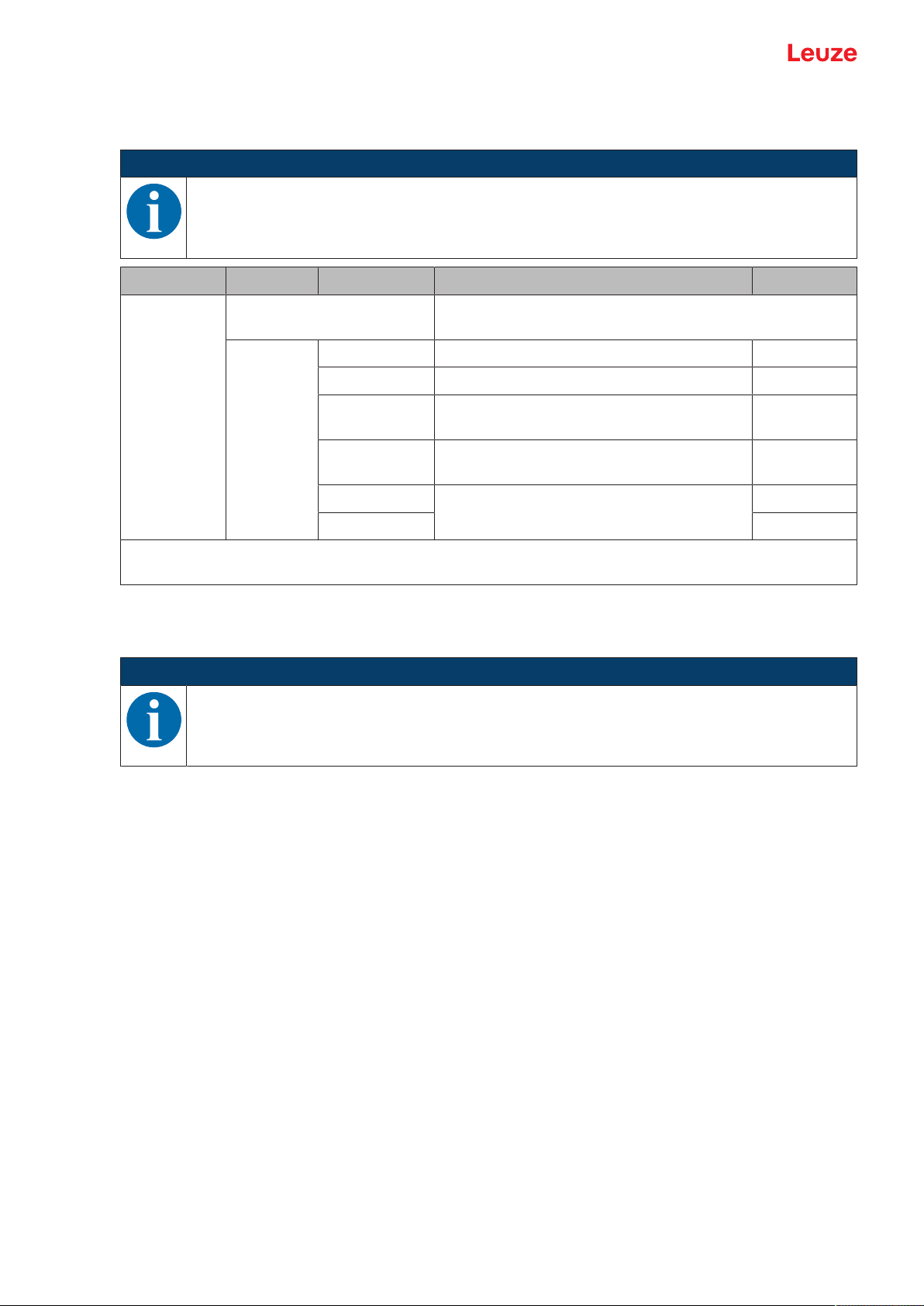
3.4.1
Input menu
The function of the switching input on pin5 is set in the Input menu.
NOTICE
The Input menu is only available for sensors with multifunction input on pin 5 (ODS9…/LAK…).
Level 1 Level 2 Level 3 Description Default
Input Input_Mode Function of the switching input on pin5 if the supply voltage
is applied.
No_Function No input function active
Teach Teach analog output and switching output X
Deactivation Switch off laser transmitter with +24V on the
switching input
Activation Switch on laser transmitter with +24V on the
switching input
Trigger_Rising The measurement value is only updated and
Trigger_Falling
output by an edge on input PIN 5.
Important: Activation or deactivation using IO-Link commands or process data (PDOut) only has an effect
if neither Deactivation nor Activation is set as the input function.
3.4.2
Output_SSC1 menu
The switching behavior of switching output SSC1 is set to pin4 in the Output_SSC1 menu.
NOTICE
Designation "SSC" corresponds to designation "Q" previously used for switching outputs.
Leuze electronic GmbH + Co. KG ODS 9 20
Page 21
Device description
Level 1 Level 2 Level 3 Description Default
Output_SSC1
SSC1_SP1_(dist.) Upper switching point Depending on the
device range:
• 100mm: 75mm
• 200mm: 175mm
• 450mm: 250mm
• 650mm: 350mm
SSC1_SP2_(near) Lower switching point 50mm
Notice: For the limit values of the measurement range for your sensor, see chapter 12
"Technical data".
SSC1_Logic Behavior of the switching output if an
object is within the taught/configured
switching distance.
High_Active Switching output active (high) X
Low_Active Switching output not active (low)
SSC1_Mode see chapter 7.1.2 "Setting the
switching outputs"
Single_Point
One switching point on the object X
(Obj)
Window Switching window Window
3.4.3
Two_Point Two switching points on the object
Single_Point
(BG)
One switching point on the background (BG), also referred to as
background-teach. Switching
process for objects between background and sensor.
Deactivated Mode deactivated
SSC1_Hysteresis Hysteresis 10mm
Output_SSC2 menu
• ODS9LA6: The switching behavior of switching output SSC2 is set to pin5 in the Output_SSC2 menu.
• ODS9L6X: The switching behavior of switching output SSC2 is set to pin2 in the Output_SSC2 menu.
NOTICE
Ä The Output_SSC2 can only be used for sensors with a second switching output SSC2.
Ä Designation "SSC" corresponds to designation "Q" previously used for switching outputs.
Leuze electronic GmbH + Co. KG ODS 9 21
Page 22

Device description
Level 1 Level 2 Level 3 Description Default
Output_SSC2
SSC2_SP1_(dist) Upper switching point Depending on the
device range:
• 100mm: 75mm
• 200mm: 175mm
• 450mm: 250mm
• 650mm: 350mm
SSC2_SP2_(near) Lower switching point 50mm
Notice: For the limit values of the measurement range for your sensor, see chapter 12
"Technical data".
SSC2_Logic Behavior of the switching output if an
object is within the taught/configured
switching distance.
High_Active Switching output active (high) X
Low_Active Switching output not active (low)
SSC2_Mode see chapter 7.1.2 "Setting the
switching outputs"
Single_Point
One switching point on the object X
(Obj)
Window Switching window Window
Two_Point Two switching points on the object
Single_Point
(BG)
One switching point on the background (BG), also referred to as
background-teach. Switching
process for objects between background and sensor.
Deactivated Mode deactivated
SSC2_Hysteresis Hysteresis 10mm
Leuze electronic GmbH + Co. KG ODS 9 22
Page 23
Device description
3.4.4
Analog_Output menu
The characteristic output curve of the analog output is set to pin2 in the Analog Output menu.
NOTICE
The Analog Output menu is only available for sensors with analog output.
Level 1 Level 2 Level 3 Description Default
Analog output
Position_Max.Val. Distance measurement value for
maximum voltage / maximum current
Position_Min.Val. Distance measurement value for
Upper limit of the
measurement
range
50mm
minimum voltage / minimum current
Notice: For the limit values of the measurement range for your sensor, see chapter 12
"Technical data".
Analog Range Current/voltage range of the analog
output
4-20_mA X
1-10_V
0-10_V
3.4.5
Spreading the characteristic output curve
You can spread the characteristic output curve of the analog output according to your requirements.
Ä Select the current or voltage range of the analog output.
Ä Set the distance measurement value that corresponds to the lower limit of the measurement range
(4mA, 1V, 0V).
Ä Set the distance measurement value that corresponds to the upper limit of the measurement range
(20mA, 10V).
It is also possible to invert the working range of the analog output, i.e., the lower limit of the measurement
range is set to a larger value than the upper limit. This creates a descending characteristic output curve.
Serial Menu
In the Serial menu, the function of the serial interface is set to pin 2 and pin 5.
NOTICE
The Serial is only available for sensors with a serial interface.
Leuze electronic GmbH + Co. KG ODS 9 23
Page 24

Device description
Level 1 Level 2 Level 3 Description Default
Serial Serial_Function Format of the measurement value output
ASCII Measurement value output correspond-
X
ing to the device resolution
14_Bit 2 byte transfer
16_Bit 3 byte transfer
24_Bit 4 byte transfer
Decimal Transfer of the measurement value as
decimal number
Remote_Control Remote control operation of the ODS via
remote commands
Reserved
Note: For the device resolution for your sensor see chapter 12 "Technical data".
Device_Address Address under which the ODS is ad-
dressed
0…14 1
Transmiss._Rate Transmission rate of the serial interface
2400_Baud
4800_Baud
9600_Baud X
19200_Baud
28800_Baud
38400_Baud
57600_Baud
115200_Baud
230400_Baud
Parity Transfer of parity bit
None X
Odd
Even
Stop_Bit Number of stop bits
1 X
2
Termination_Byte If not equal to 0, the corresponding char-
acter is appended
0…255 0
Transmiss._Delay Delay of data transmission in millisec-
onds
0…255 0
Leuze electronic GmbH + Co. KG ODS 9 24
Page 25
Device description
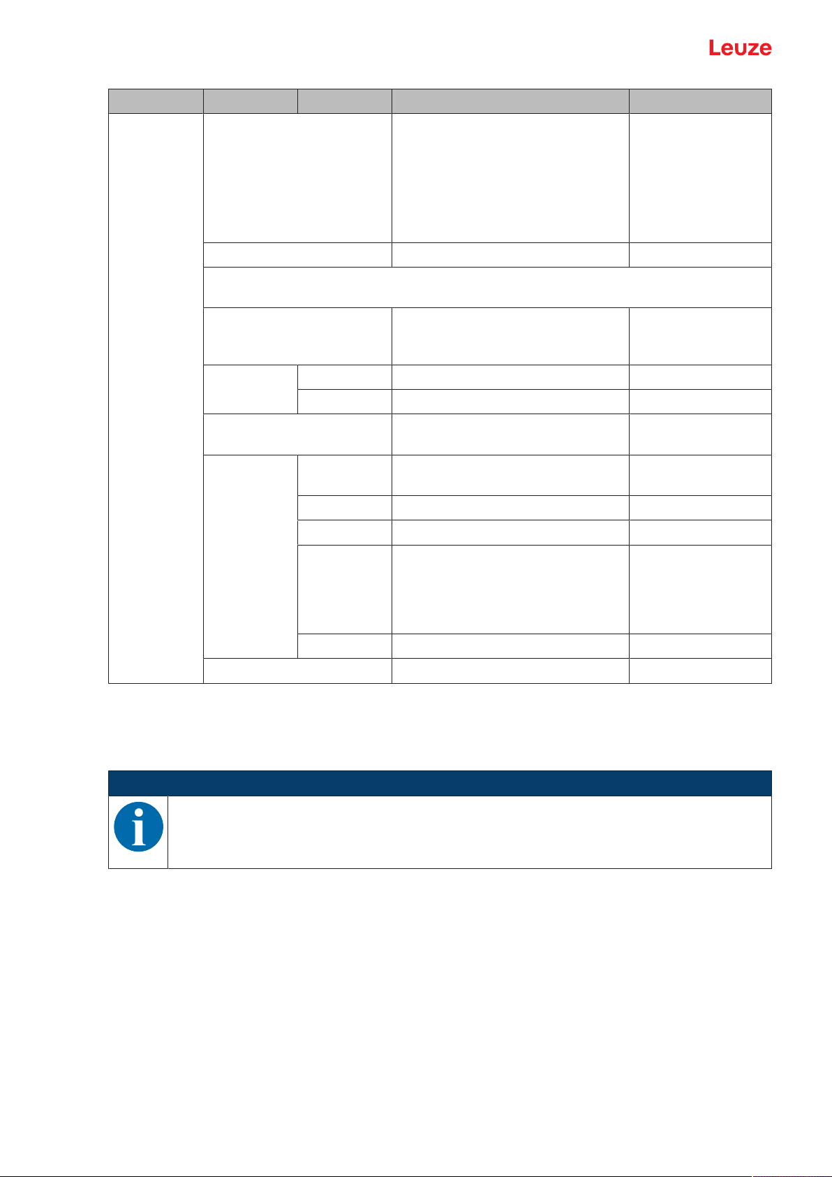
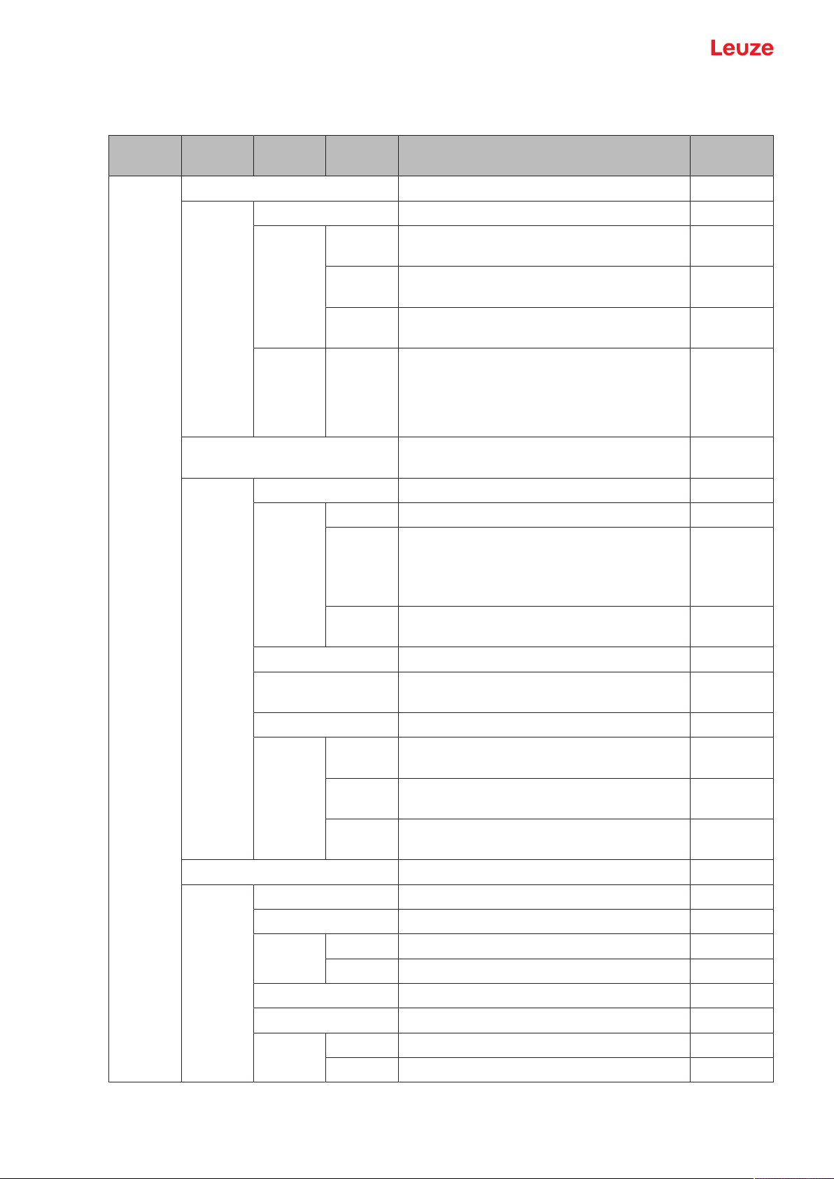
3.4.6
Application menu
The measurement function of the sensor is set in the Application menu.
Level1 Level2 Level3 Selection
Description Default
level 3
Application
Process_Settings Measurement value processing
Measurem._Mode
Standard Multi-purpose function for many measure-
ment tasks
Precision Greater accuracy for less dynamic applica-
tions
Light_Sup-
Ambient light sensitivity
pression
LightSupp
r.Limit
2…32 Setting of the maximum number of measure-
ments for preventing the sensor from measuring for too long if the light is too bright
and, as a result, not outputting a measurement value.
Filter_Settings Filter for ascertaining and suppressing out-
liers
Filter_Type
X
32
None X
Averaging Floating average calculation taking 2…99
measurements into account
The response time increases with the number of measurements.
Spike_Su
ppression
Blocked central value filtering across buffer
sizes from 5…99 measurements
Average_Count Number of measurements used in averaging 10
Spike_Supp.Count Number of measurements used in outlier
suppression
Spike_Supp.Depth Adjustable filter depth for outlier suppression
Raw Averages approx. 75% of the central mea-
surement values
Medium Averages approx. 50% of the central mea-
surement values
Fine Averages approx. 25% of the central mea-
surement values
Dist.Correction Distance calibration
Offset 0mm
10
X
Gradient
Rising X
Falling
Preset_Position 0mm
Preset_Calc.
Inactive X
Execute
Leuze electronic GmbH + Co. KG ODS 9 25
Page 26
Device description
Measurement value processing and filtering is set according to the given requirements and the application
via the display or using the SensorStudio configuration software.
By changing the measurement value processing or filtering, the response time and accuracy can be increased.
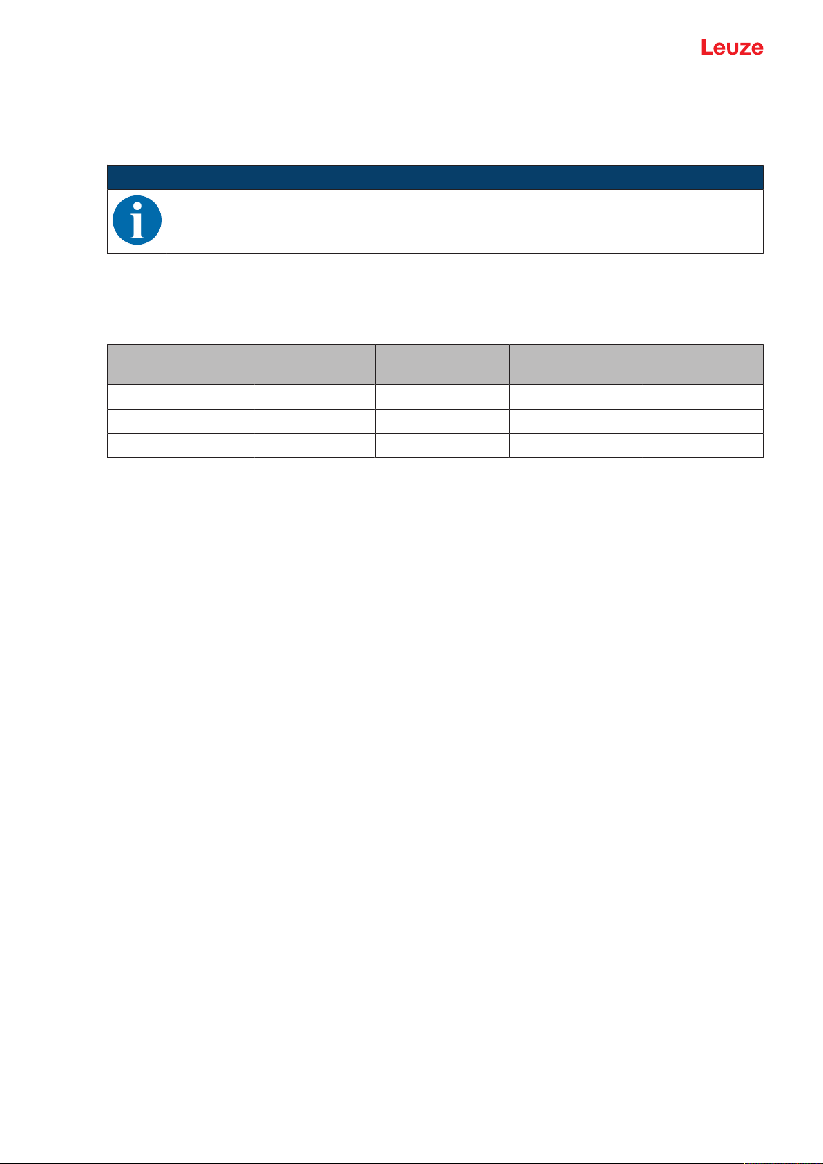
Measurement value processing
Processing settings > Measure mode > Standard/Precision/Ambient light
Tab.3.3: Measurement value processing
NOTICE
A higher response time presupposes the possibility of measuring an object for a longer period.
Accuracy Measurement
time / reload
Ambient light Varying diffuse
reflection
Standard + + + +
Precision ++ -- + +
Ambient light + -- ++ 0
Filter
Filter settings > Filter type > Averaging/outlier suppression
A floating average value is calculated over the number of set measurement values.
The measurement value noise decreases, i.e., measurement value fluctuations become smaller.
If the measurement value changes erratically, the output value moves linearly from the old measurement
value to the new measurement value over n measurements.
The higher the number of measurements is set, the higher the response time of the sensor. With dynamic
applications, averaging should be set to a very low number of measurement values or switched off altogether.
The time of measurement value updating is not affected by the filtering.
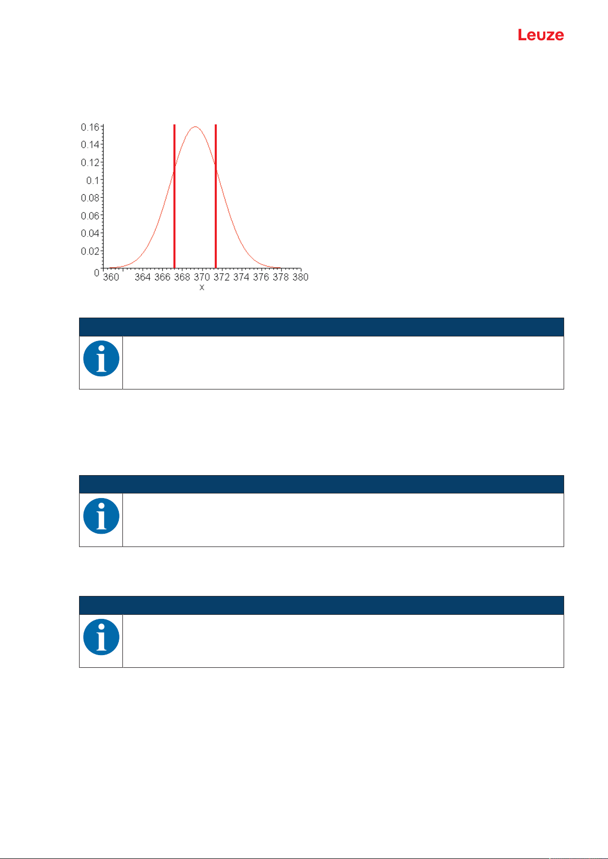
Outlier suppression
Filter settings > Degree of suppression > Coarse/Medium/Strong
Measurement results with excessively high or low measurement values (referred to as "outliers" or
"spikes") are suppressed or rejected according to the set filter depth.
• The user sets the number of measurements via the display or using the configuration software Sen-
sorStudio .
• The sensor performs the set number of measurements on the object, e.g. 100measurements.
Due to physical reasons, the measurement results are not all the same. The measurement values have a
scatter which corresponds to a normal distribution comprising a large number of similar measurement values and a small number of excessively high or low measurement values (outliers, spikes).
Leuze electronic GmbH + Co. KG ODS 9 26
Page 27

Device description
The suppression or rejection of the measurement value outliers is configured in the following levels using
the filter depth:
• Coarse: A large number of measurement values which do not occur with a high frequency are suppressed or rejected.
• Falling on one side: 12%
• Used center area, averaged: 76%
Fig.3.3: Coarse filter depth
• Medium
• Falling on one side: 24%
• Used center area, averaged: 52%
Fig.3.4: Medium filter depth
Leuze electronic GmbH + Co. KG ODS 9 27
Page 28
Device description
• Strong
• Falling on one side: 36%
• Used center area, averaged: 28%
Fig.3.5: Strong filter depth
NOTICE
In the case of dynamic applications with erratic changes in measurement distance, it is recommended to filter by setting the response time.
Distance calibration "Distance correction"
Under the Distance correction menu item, you can influence the output of the measured distance value.
Gradient
If the gradient is changed from rising to falling, the measurement values decrease as the distance from the
object to the sensor increases. The distance information is output inverted.
NOTICE
Negative measurement values may result if the gradient is reversed.
Offset and Preset
Deviations that arise while mounting and attaching the sensor can be compensated for with the entries for
the Offset and Preset parameters.
NOTICE
Negative measurement values may occur if an offset is set.
The offset/preset calculation is available as a teach function. The assignment of the teach time frame can
be read out via IO-Link (see chapter 7 "Starting up the device").
Specify offset and preset
Under the Application > Dist.Correction menu item, you can influence the output of the measured distance value. The Offset and Preset parameters are used for correcting the measurement value by a fixed
amount.
Leuze electronic GmbH + Co. KG ODS 9 28
Page 29

Device description
Deviations that arise while mounting and attaching the sensor can be compensated for with the entries for
the Offset and Preset parameters.
• For the Offset parameter, a fixed value and sign are specified.
• For the Preset parameter, a nominal measurement value is specified; a measurement is then performed using an object located at the desired nominal distance. The Offset parameter is changed as a
result of this measurement.
Setting the offset
Ä Enter an offset value via the display:
Application > Dist.Correction > Offset
ð The set offset value is added to the measured distance value of the sensor.
Example:
• Measurement value of the ODS9: 1,500mm
• Entry offset-value: -100mm
• Output on the display and at the interface: 1400mm
NOTICE
If the calculation of the Offset parameter results in negative measurement values, zero is output
at the interface and on the display.
Preset presetting
Ä Enter a Preset value via the display or using the Sensor Studio configuration software (IO-Link):
Application > Distance correction > Preset position
Ä Position an object at the desired preset distance.
Ä Perform the preset measurement:
Application > Distance correction > Preset calculation > Execute
ð The offset value is automatically calculated from the measurement value and nominal measurement
value (preset value) and entered as the offset in the configuration.
Example:
• Entry: preset value 350mm
• Object distance: 300mm in front of the sensor
Trigger preset measurement
Distance correction > Preset calculation > Execute
An offset of +50 mm is automatically calculated and stored in the configuration.
• Object distance: 300mm
Output to display and interface: 350mm
• Object distance: 400mm
Output to display and interface: 450mm
Leuze electronic GmbH + Co. KG ODS 9 29
Page 30
Device description
3.4.7
Settings menu
You can set the display language and call up information about the sensor in the Settings menu.
Level 1 Level 2 Level 3 Description Default
Settings Language Setting of the display language
Note: If the display language is changed, this change only
becomes effective when the sensor is restarted.
English Display language English X
Deutsch Display language German
Display Display settings
Auto After pressing a control button, the display is
X
set to full brightness for approx. one minute.
The display is then dimmed slightly for five
minutes and then dimmed considerably.
Auto_Off The display (measurement value display) is
automatically switched off after approx.
sixminutes.
Off No measurement value display – the display
is only active in the menu after pressing a
control button.
On The display (measurement value display) is
always at full brightness.
Factory_Settings Reset to factory settings
Inactive The sensor is not reset to factory settings. X
Execute The sensor is reset to factory settings.
Password_Lock Locks access to the menu with the fixed password 165
Inactive Inactive X
Activated Active
Exit_behaviour Exit the configuration settings
Report_to_DS After making a change in the menu, the
X
change is taken over in the data memory after returning to measurement operation. The
DSUpload flag is set.
The "Data Storage" (DS) parameter memory
is updated.
Only_local_changes
The change is only temporary or local on the
device or no data memory is used.
The DSUpload flag is cleared.
Info Information on the sensor
Part_No. Leuze part number of the sensor
Serial_No. Sensor serial number
Firmware_Re-
Firmware version
vision
Leuze electronic GmbH + Co. KG ODS 9 30
Page 31

Device description
3.4.8
Ending configuration
With IO-Link data storage, the behavior upon ending the configuration settings can be changed in the following ways in the Settings menu.
Tab.3.4: Settings > Exit behavior
Menu item Use Display of the menu item
Report to DS
(Report to DS)
Changes in the menu are taken
over in the data memory after
returning to measurement oper-
A change was performed and the data memory
updated.
ation. The DSUpload flag is set.
Only local changes
(only local changes)
The change is only temporary or
local on the device or no data
memory is used. The DSUpload
A change was made only locally on the device.
flag is cleared.
Central storage of configuration data
If the configuration setting is ended with subsequent adoption of the data in the data memory of a connected IO-Link master, the sensor does not need to be newly configured if a device is changed.
The sensor adopts the configuration from the data memory of the connected IO-Link master, provided that
the IO-Link master is capable of doing this and enabled accordingly.
Timeout
If the configuration setting is ended due to a timeout, the previously made changes are always reported by
default to the data memory (Data Storage, DS). If an IO-Link master is connected, the changes are transferred to its data memory. The status of the DSUpload flag is not changed.
If the DSUpload flag is not set and the changes are only stored locally, after reconnection the change is
overwritten by the configuration which is stored in the data memory of the connected IO-Link master.
NOTICE
If the sensor is not operated via an IO-Link master, these settings do not need to be made.
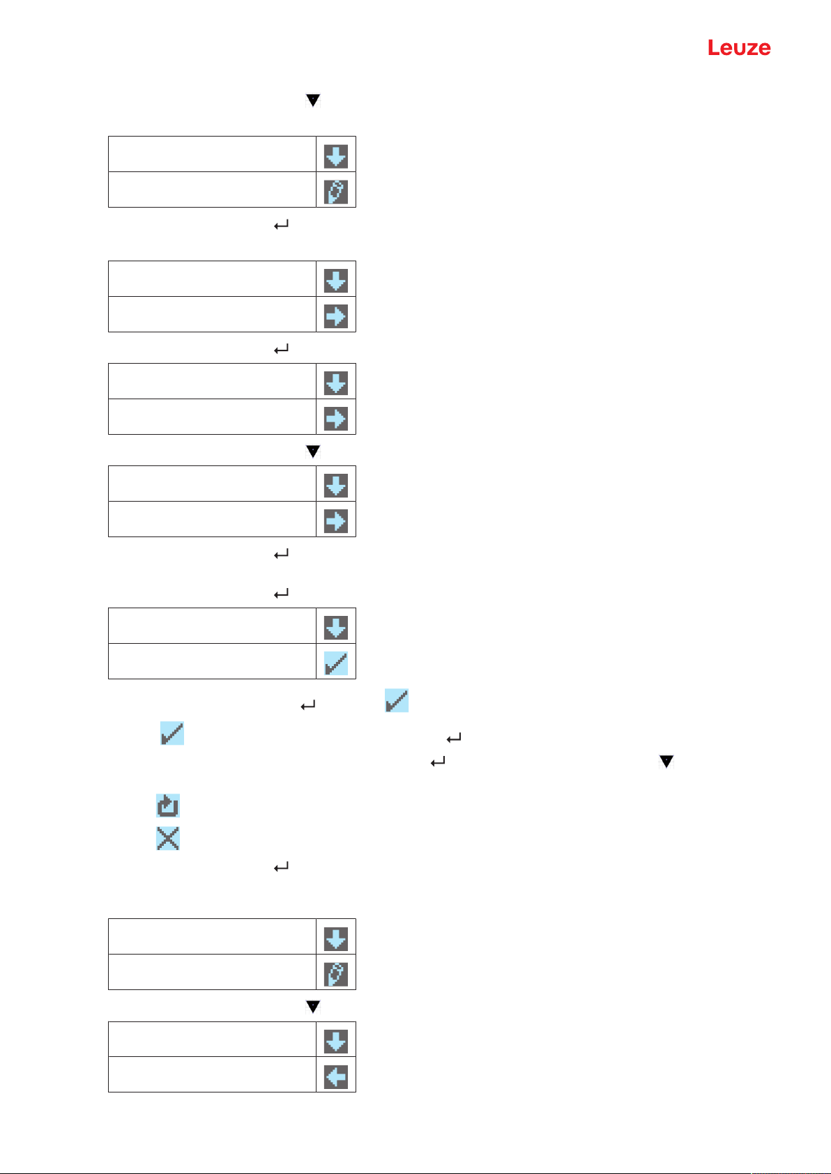
3.5 Configuration example
To illustrate menu operation, the setting of the lower switching point of switching output SSC1 to 100mm is
explained as an example.
Ä In process mode, press a control button to activate the menu display.
Input
Output SSC1
Ä Press the navigation button .
ð The display shows "Output SSC1" in the upper menu line.
Output SSC1
Output
Ä Press the enter button to select Output SSC1.
SSC1 SP1 (dist.)
00250mm
Leuze electronic GmbH + Co. KG ODS 9 31
Page 32
Device description
Ä Press the navigation button once.
ð The display shows "SSC1 SP2 (near)" in the upper menu line.
SSC1 SP2 (near)
00050mm
Ä Press the enter button to set the lower switching point.
ð The first digit of the switching point value is displayed with inverted colors.
SSC1 SP2 (near)
00050mm
Ä Press the enter button twice until the hundreds digit is inverted.
SSC1 SP2 (near).
00050mm
Ä Press the navigation button as many times as necessary to set the desired value “1”.
SSC1 SP2 (near)
00150mm
Ä Press the enter button to accept the set value.
Ä Repeat the setting for digit 5 until the complete value “00100” is set.
Press the enter button to move to the units digit.
SSC1 SP2 (near)
00100mm
After pressing the enter button again, the icon appears in the lower right part of the display.
• The icon indicates that the next time the enter button is pressed, the set value will be accepted.
• You can change the function of the enter button by pressing the navigation button several times.
The following icons are displayed in succession:
• : re-edit value
• : reject value
Ä Press the enter button to accept the set value 00100.
ð "SSC1 SP2 (near)" is displayed inverted in the display.
The newly set value “00100mm”, which is stored in non-volatile memory, appears in the display.
SSC1 SP2 (near)
00100mm
Ä Press the navigation button repeatedly until the←icon appears in the upper menu line.
←
SSC1 SP1 (dist.)
Leuze electronic GmbH + Co. KG ODS 9 32
Page 33

Device description
Ä Press the enter button to access the next-higher menu level.
Output SSC2
Analog output
Ä Press the enter button to exit the menu display and access process mode.
Quick exit
If you do not wish to make any further configuration settings, you can exit the menu via Quick exit and return to process mode.
225mm
NOTICE
The DSUpload upload flag is always set on quick exit. This means that parameter changes are
passed on to the connected IO-Link master.
Ä Press and hold down the enter button for at least 5 s – until the "Exit menu" message appears on
the display.
Ä Confirm with the enter button .
Leuze electronic GmbH + Co. KG ODS 9 33
Page 34

Applications
4 Applications
The laser distance sensor is designed for the following areas of application:
• Distance measurement
• Thickness measurement
• Positioning
• Diameter determination
• Fill level indicator
4.1 Wood width measurement
Fig.4.1: Application example: wood width measurement
Leuze electronic GmbH + Co. KG ODS 9 34
Page 35
Applications
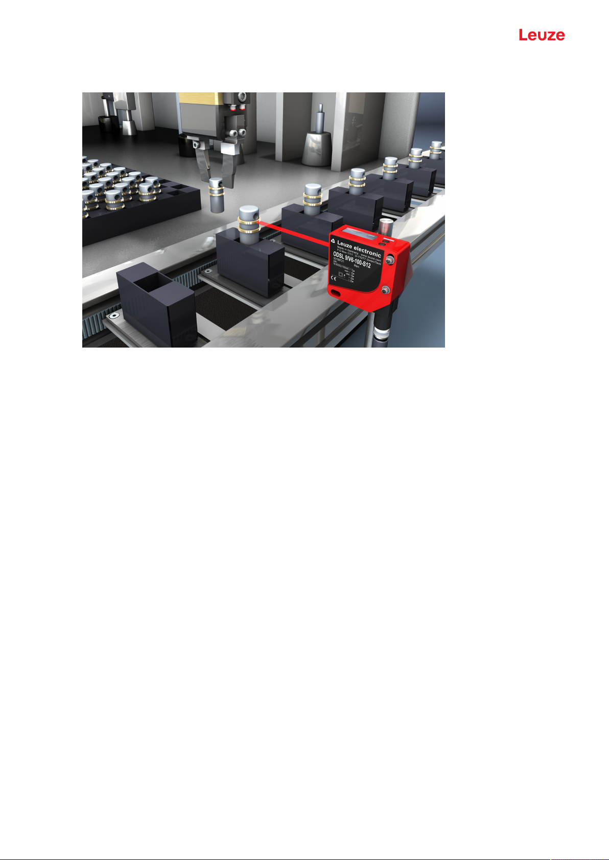
4.2 Assembly inspection
Fig.4.2: Application example: assembly inspection
Leuze electronic GmbH + Co. KG ODS 9 35
Page 36

Mounting
5 Mounting
The sensor can be mounted in the following ways:
• Mount using a mounting system
• BTU300M-D10: mounting on rod Ø 10mm
• BTU300M-D12: mounting on rod Ø 12mm
• BTU300M-D14: mounting on rod Ø 14mm
NOTICE
Observe during mounting!
Ä Make certain that the required environmental conditions (humidity, temperature) are main-
tained.
Ä Make certain that the optics cover of the sensor is not soiled, e.g., by leaking fluids, abrasion
from boxes or residues from packaging material.
Ä When mounting behind a cover: Make certain that the cutout in the cover is at least as large
as the lens cover of the sensor. Correct measurement cannot otherwise be ensured.
5.1 Mounting with mounting system
Mounting with a mounting system is intended for rod mounting. For ordering information, see chapter 13.3
"Other accessories".
Ä Mount the mounting system on the rod (system-side).
Ä Mount the sensor on the mounting system with M4 fastening screws (not included in delivery contents).
Max. tightening torque of the fastening screws: 1.4Nm
Leuze electronic GmbH + Co. KG ODS 9 36
Page 37

Electrical connection
Analog OUT
6 Electrical connection
6.1 Overview
The assignment of the electrical connections is dependent on the type of sensor that is used. The type designation of the sensor is specified on the name plate.
CAUTION
Safety notices!
Ä Before connecting the device, be sure that the supply voltage agrees with the value printed
on the name plate.
Ä Only allow competent persons to perform the electrical connection.
Ä Ensure that the functional earth (FE) is connected correctly.
Fault-free operation is only guaranteed if the functional earth is connected properly.
Ä If faults cannot be rectified, take the sensor out of operation. Protect the sensor from acci-
dentally being started.
NOTICE
Protective Extra Low Voltage (PELV)
Ä The sensor is designed in accordance with protection class III for supply with PELV (protec-
tive extra-low voltage with reliable disconnection).
NOTICE
Ä For all connections (connection cable, interconnection cable, etc.), use only the cables listed
in the accessories (see chapter 13.2 "Accessories – cables and connectors").
Ä Use shielded cables when using the analog interface. You can thereby prevent interference
caused by electromagnetic fields.
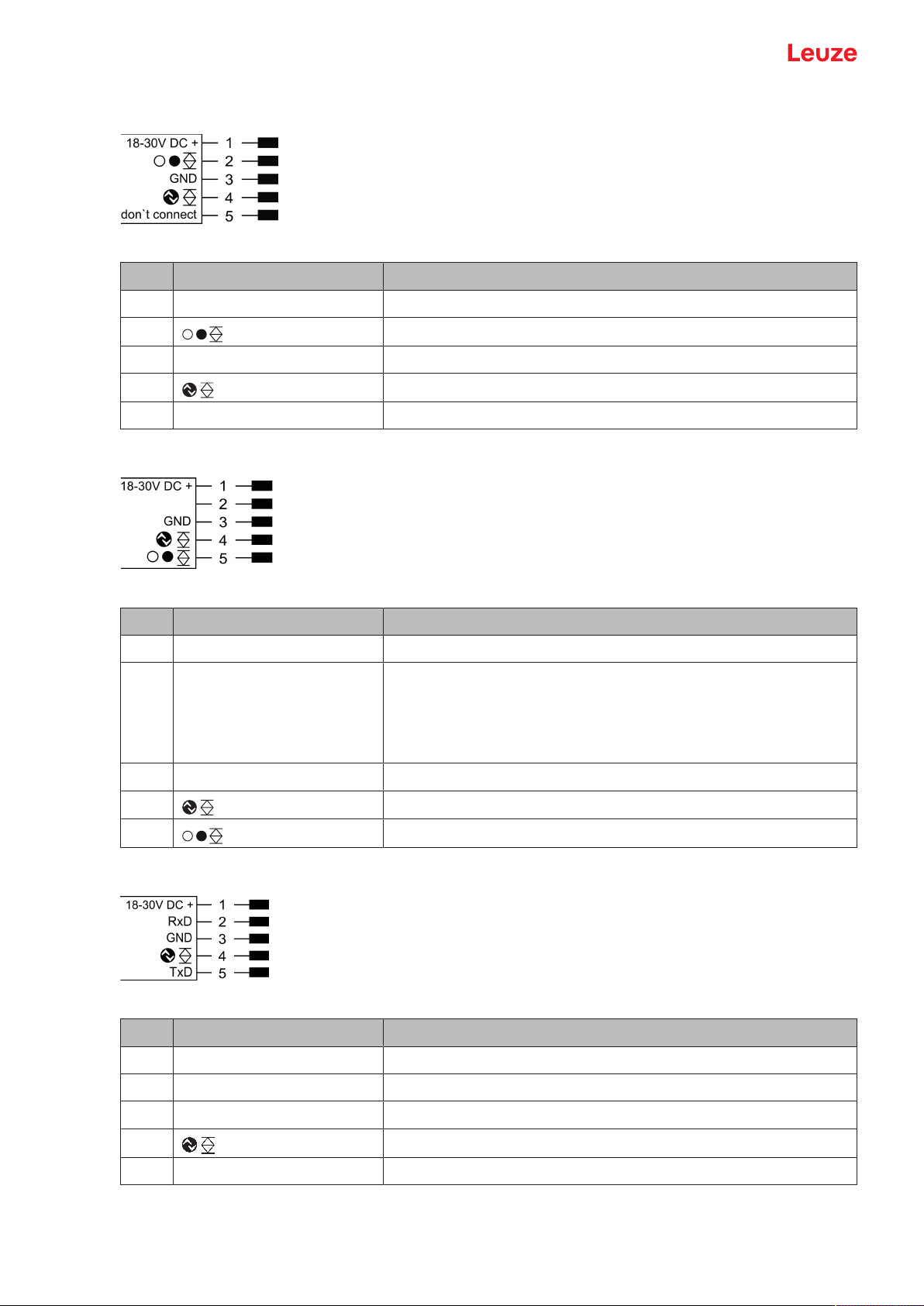
6.2 Pin assignment
Pin assignment ODS9L2.8/LAK-…-M12
Fig.6.1: Pin assignment
Pin Designation Assignment
1 18-30VDC+ Supply voltage
2 Analog OUT Configurable analog output
• Current: 4mA…20mA
• Voltage: 1V…10V, 0V…10V
Factory setting: Current
3 GND Functional earth
4 IO-Link / switching output1, push-pull
5 IN Function of the switching input
Leuze electronic GmbH + Co. KG ODS 9 37
Page 38
Electrical connection
Analog OUT
Pin assignment ODS9L2.8/L6X-…-M12
Fig.6.2: Pin assignment
Pin Designation Assignment
1 18-30VDC+ Supply voltage
2 Switching output2, push-pull
3 GND Functional earth
4 IO-Link / switching output1, push-pull
5 don’t connect don’t connect
Pin assignment ODS9L2.8/LA6-…-M12
Fig.6.3: Pin assignment
Pin Designation Assignment
1 18-30VDC+ Supply voltage
2 Analog OUT Configurable analog output
• Current: 4mA…20mA
• Voltage: 1V…10V, 0V…10V
Factory setting: Current
3 GND Functional earth
4 IO-Link / switching output1, push-pull
5 Switching output2, push-pull
Pin assignment ODS9L2.8/LFH-…-M12
Fig.6.4: Pin assignment
Pin Designation Assignment
1 18-30VDC+ Supply voltage
2 RxD Signal RxD of the RS232 serial interface
3 GND Functional earth
4 IO-Link / switching output1, push-pull
5 TxD Signal TxD of the RS232 serial interface
Leuze electronic GmbH + Co. KG ODS 9 38
Page 39

Electrical connection
Pin assignment ODS9L2.8/LQZ-…-M12
Fig.6.5: Pin assignment
Pin Designation Assignment
1 18-30VDC+ Supply voltage
2 D– Signal D– of the RS485 serial interface
3 GND Functional earth
4 Switching output
5 D+ Signal D+ of the RS485 serial interface
Leuze electronic GmbH + Co. KG ODS 9 39
Page 40
Starting up the device
7 Starting up the device
7.1 Teaching and configuring output functions
7.1.1
Setting the analog output
The sensors are equipped with an analog output with linear response within the respective measurement
range.
Above and below the measurement range linearity is not obtained. If a signal is present, the output values
can be used to determine whether the measurement range is exceeded or not met.
In order to achieve the highest resolution possible, set the range of the analog output as small as the application allows. The characteristic output curve can be configured as rising or falling, e.g. for fill level applications.
The output can be switched to current or voltage with the following ranges:
• 4…20mA
• 1…10V
• 0…10V
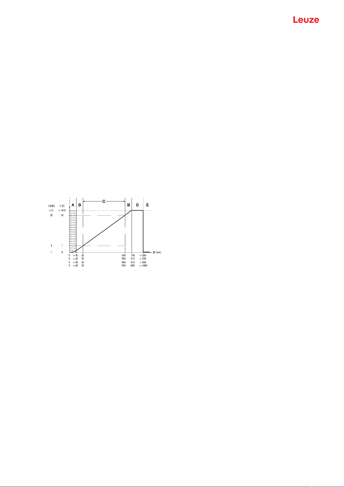
To configure the analog output, the two distance values Position Min. Val. and Position Max. Val. are specified at which the respective minimum or maximum analog value is output.
Measurement range C is assigned ex works (see figure), e.g., 50…100mm for device types -100.
A Area not defined
B Linearity not defined
C Measurement range
D Object present
E No object detected (characteristic curve behavior configurable via IO-Link)
F Measurement distance
Fig.7.1: Characteristic curve of analog output ODS9L2.8/LA…-M12
Setting the analog output
You can set the characteristic output curve for the analog output as follows:
• Directly changing the parameters:
• On the device via the OLED display and the control buttons (see chapter 3.4 "Configuration / menu
structure")
• Via the SensorStudio configuration software (see chapter 8 "Connecting to a PC – SensorStudio").
• Teach-in / teach:
• Via IO-Link (see chapter 7.1.5 "Teaching the output functions via the IO-Link system commands"),
especially using the SensorStudio configuration software (see chapter 8 "Connecting to a PC –
SensorStudio").
• Via the multifunction input with set Teach input function (see chapter 7.1.4 "Teaching the output
functions via the multifunction input").
Leuze electronic GmbH + Co. KG ODS 9 40
Page 41

Starting up the device
OFF
ON
OFF
ON
1
2
4
3
3
7.1.2
Setting the switching outputs
All sensors are equipped with at least one SSC1 switching output. LA6 model sensors are provided with a
second SSC2 switching output.
For each switching output you can configure the following parameters:
• Upper and lower switching point
• Switching hysteresis
• Switching logic
• Light switching (high active)
• Dark switching (low active)
• Switching point mode
NOTICE
The output state in the hysteresis area is not uniquely defined!
The output state in the hysteresis area is dependent on the previous situation.
If the output in the hysteresis area is permanently set to high active, a short detection failure (no
signal, e.g., due to a target that is marginally dark) results in a change to permanently low active
(dark switching).
1 Light switching
2 Dark switching
3 Hysteresis
4 Measurement distance
Fig.7.2: Switching output configuration
The switching outputs can be set via the OLED display and the control buttons (see chapter 3.5 "Configuration example"), but also via the multifunction input on pin 5 and via IO-Link system commands.
NOTICE
For sensor models with multifunction input, there is only one physically present switching output
that can be taught in.
Leuze electronic GmbH + Co. KG ODS 9 41
Page 42
Starting up the device
1
3
2
3
4
5
6
1
Configuring switching point modes
The following switching point modes can also be configured. These are structured according to the switching profiles of the Smart Sensor Profile specification.
• SinglePoint Object mode (SinglePtObj): single switching point taught on an object
• Window: window mode
• TwoPoint: two-point mode
• SinglePoint Background mode (SinglePtBG): single switching point taught against a background
SinglePoint Object mode (SinglePtObj)
When teaching setpoint SP1 before of after, the object (Obj) is targeted, i.e., with SP1, the SSC is still active. The SSC becomes inactive only after SP1.
1 Setpoint SP1
2 Measurement range minimum
3 Hysteresis
4 Signal response
5 Sensor/SSC
6 Reserve if >0
Fig.7.3: SinglePoint Object switching point mode
• Only setpoint SP1 (not SP2) is used for calculating the switching edges. The lower switching edges are
always at the lower limit value.
• Reserve and hysteresis run from the upper switching point into the distance, so that the switching output has reliably (i.e., with reserve) switched on after the teach event (provided it is light switching high
active).
Leuze electronic GmbH + Co. KG ODS 9 42
Page 43

Starting up the device
1
3
4
3
2
5
6
7
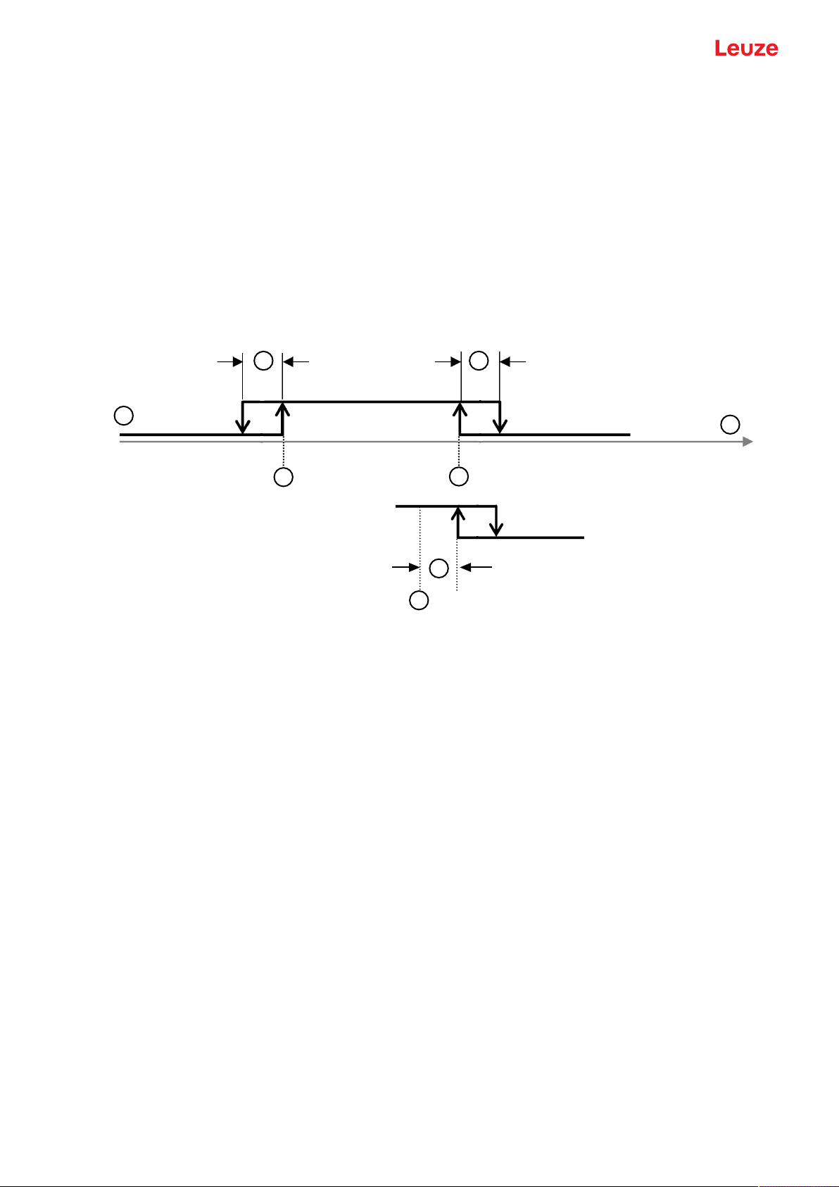
Window – window mode
Teach point is midway between the equidistantly shifted setpoints S2 (near) and SP1 (far)
1 Setpoint SP1 (far)
2 Setpoint SP2 (near)
3 Hysteresis
4 Teach point
5 Sensor/SSC
6 Signal response
7 Window
Fig.7.4: Switching point mode window
• Hysteresis runs to the outside.
• Reserve is not used.
Leuze electronic GmbH + Co. KG ODS 9 43
Page 44

Starting up the device
12
3
5
6
7
4
TwoPoint – two-point mode
• Closer than setpoint SP2, the output is set to high active (as with the Single Point modes).
• The "far" hysteresis area lies between setpoint SP2 and setpoint SP1; the Hysteresis parameter is not
used here.
• After setpoint SP1, the output is set to low active.
1 Setpoint SP1
2 Setpoint SP2
3 Hysteresis "near"
4 Hysteresis "far"
5 Sensor/SSC
6 Signal response
7 Measurement range minimum
Fig.7.5: TwoPoint switching point mode
NOTICE
The Hysteresis parameter is used for the switch-on/switch-off edges at the start of the measurement range.
Ä If setpoint SP2 is too close to the switch-on edge, the assigned switching edge is shifted into
the distance by the distance of the Hysteresis parameter.
Ä If, afterwards, setpoint SP1 is closer than the shifted edge, the edge assigned to setpoint
SP1 is placed on the shifted SP2 edge. The two far switching edges then decrease together.
NOTICE
The output state in the hysteresis area is not uniquely defined!
The output state in the hysteresis area is dependent on the previous situation.
If the output in the hysteresis area is permanently set to high active, a short detection failure (no
signal, e.g., due to a target that is marginally dark) results in a change to permanently low active
(dark switching).
Leuze electronic GmbH + Co. KG ODS 9 44
Page 45
Starting up the device
12
3 3
4
5
1
6
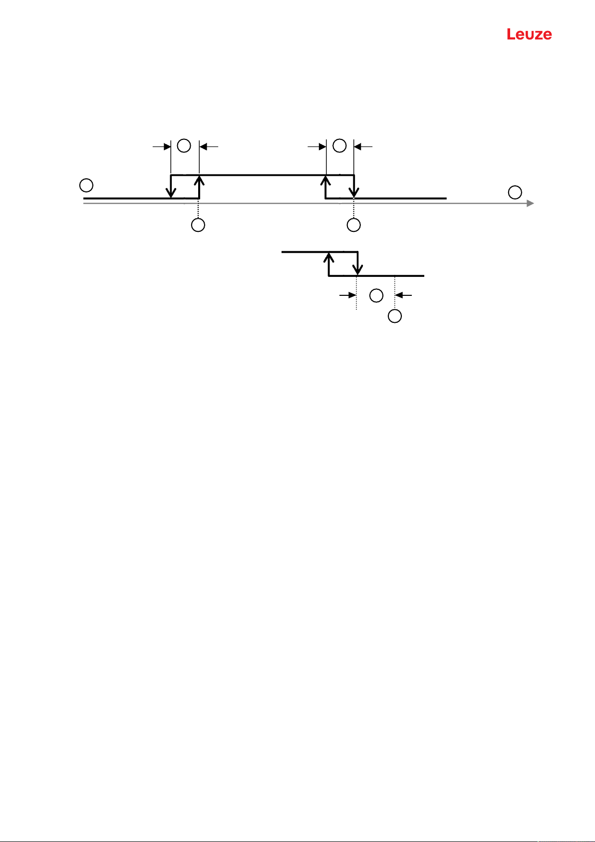
SinglePoint Background mode (SinglePtBG)
When teaching setpoint SP1 before of after, the background (BG) is targeted, i.e., with setpoint SP1, the
SSC must no longer be active. The SSC is only active before setpoint SP1.
1 Setpoint SP1
2 Measurement range minimum
3 Hysteresis
4 Signal response
5 Sensor/SSC
6 Reserve if >0
Fig.7.6: SinglePoint BG switching point mode
• Only setpoint SP1 (not SP2) is used for calculating the switching edges. The lower switching edges are
always at the lower limit value.
• Reserve and hysteresis run from the upper switching point into the near range, so that the switching
output has reliably (i.e., with reserve) switched off after the teach event (provided it is light switching
high active).
Leuze electronic GmbH + Co. KG ODS 9 45
Page 46
Starting up the device
0V
T
t
+24V
7.1.3
Teach-in / teach
Teaching offers the possibility to adjust certain parameters based on the current measurement situation.
Focus here is primarily on settings that affect the output functions, i.e., analog output and the switching output(s).
The teaching action is triggered in the following ways:
• Via the multifunction input when setting the input function to Teach (see chapter 7.1.4 "Teaching the
output functions via the multifunction input")
• Via IO-Link system commands (see chapter 7.1.5 "Teaching the output functions via the IO-Link system commands")
• Special teach via the device menu (OLED display and control buttons)
When completed, each successful teach returns a so-called teach point (TP), which is formed by averaging
multiple individual measurements.
• Prerequisite for successfully teaching is a minimum number of valid measurement values. Objects that
are marginally dark and/or distant objects can increase the teach time.
• The teachable areas are limited by model.
• A teach point may only be located within the measurement range described in the table in order for an
assignment to the respective, likewise limited parameters to be possible.
Device Outside of the
operating
range (-)
(Out of Range
(-))
(measurement value shown on the display)
Operating range [mm]
Outside of the
operating range
(+)
(Out of
Range(+))
7.1.4
Limited accuracy
…-100-… Directly under-
…-200-… 47.00 50.00 200.00 220.00
neath
47.00 50.00 100.00 110.00 Directly above
Measuring range Limited
accuracy
…-450-… 47.0 50.0 450.0 500.00
…-650-… 47.0 50.0 650.0 700.00
Teaching the output functions via the multifunction input
NOTICE
The information in this chapter only applies for devices that are equipped with a multifunction input on pin 5 (ODS9…/LAK-…).
To teach, a teach signal is applied to the multifunction input (pin 5). The duration of the teach signal (low
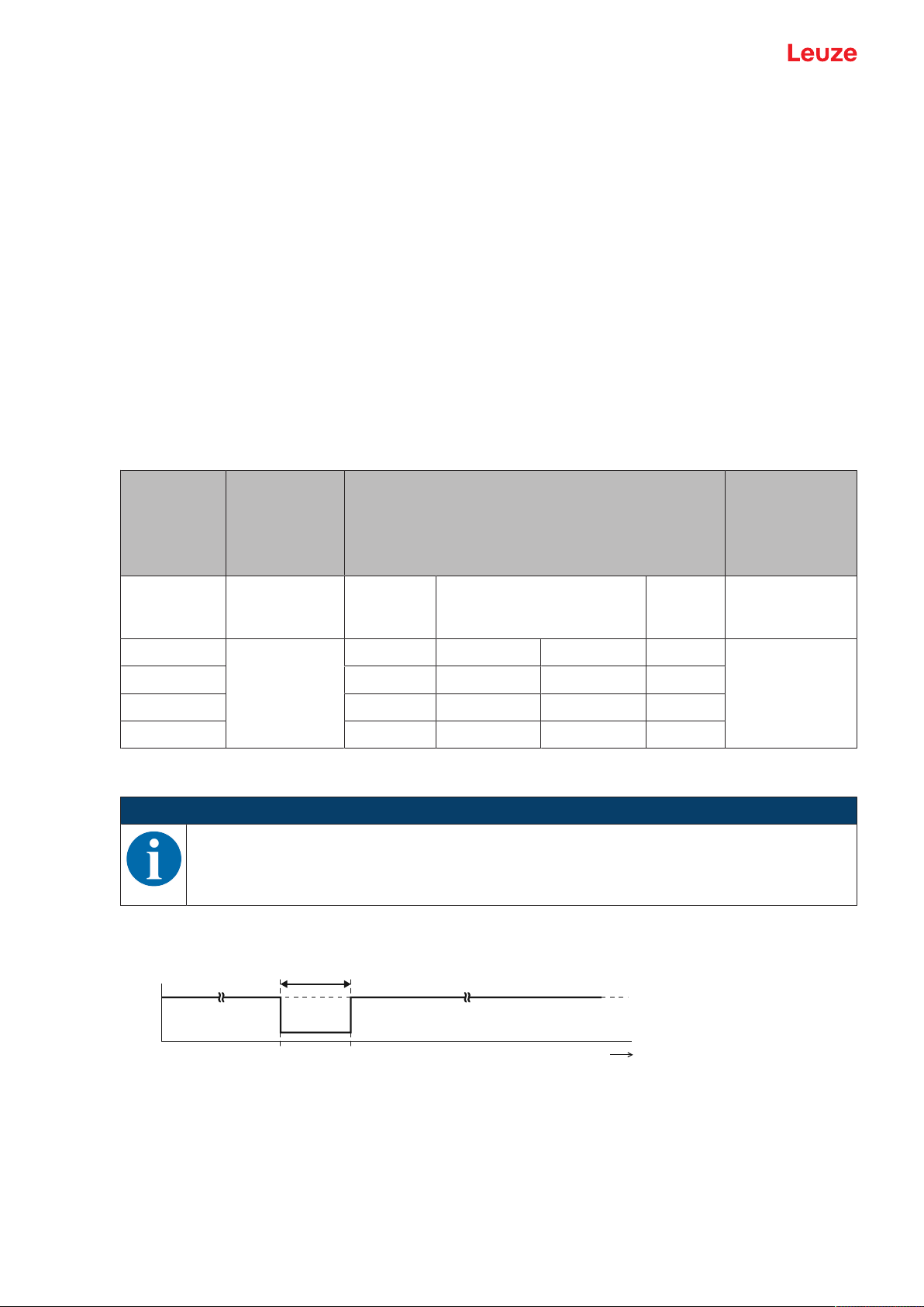
level on the teach input) determines the teach-in function.
T Duration of the teach signal
Fig.7.7: Plot of the teach signal
To teach, proceed as follows:
Ä In the Configuration menu, activate the input function Teach (Default)
Input > Input mode > Teach
Leuze electronic GmbH + Co. KG ODS 9 46
Page 47
Starting up the device
Ä Position the measurement object at the desired distance.
NOTICE
The teachable area must be located within the measurement range of the sensor.
Ä Apply the teach signal to the multifunction input (pin 5).
• The duration T of the low level at the teach input determines the teach-in function.
• The teach functions assigned to the time frames are preset and can be queried via IO-Link.
Tab.7.1: Default assignment of the teach functions
Duration T [ms] Teach function Function no.
20…80 Object teach of switching output SSC1 14
120…180 Window teach (Window) of switching output SSC1 15
220…280 Analog teach of the distance value for the smallest analog value
6
(4mA, 1V, 0V) on pin 2
320…380 Analog teach of the distance value for the largest analog value
7
(20mA, 10V) on pin 2
420…480 Preset-Offset calculation:
8
determination of an offset value so that the preset Preset value is
output as measurement value.
520…580 Background-Teach_SSC1 16
620…680 Setpoint1-Teach SP1_SSC1 12
720…780 Setpoint2-Teach SP2_SSC1 13
820…880 Alternative setpoint1-Teach SP1a_SSC1 17
920…980 Logic of SSC1 to 0 "light switching" Light_SSC1 19
1020…1080 Logic of SSC1 to 1 "dark switching" Dark_SSC1 20
1120…1180 Toggle logic of SSC1 "light/dark switching" 18
Corresponding IO-Link object:
Index 140, teach level assignment (Wire Function Array)
Ä Detection and averaging of measurement values for forming the teach point TP begins with the rising
edge of the input signal.
The parameter or parameters assigned to the time frame for the teach signal is/are updated based on
the teach point.
NOTICE
Ä With the preset assignment of the teach functions, teaching can only be performed via the
multifunction input in SinglePoint Object mode (see chapter 7.1.2 "Setting the switching outputs").
Only the upper setpoint SP1 is then shifted, so that the targeted object is just detected
(switching output triggered). More distant objects are no longer detected.
Ä Other teach modes are possible via IO-Link system commands (see chapter 7.1.5 "Teach-
ing the output functions via the IO-Link system commands").
Ä Alternatively, the assignment table assignments can also be changed or expanded for ap-
plicative optimization.
NOTICE
A complete process data map of all function indices can be generated via the IODD file. You
can find the IODD file on the Internet at www.leuze.com.
Leuze electronic GmbH + Co. KG ODS 9 47
Page 48

Starting up the device
Ä In the following cases, perform two successive teach actions:
• Analog output: teach the two positions for start and end of the analog value range
• Switching output: individually teach setpoints SP1 and SP2 in Window or Two-Point mode
Ä Ensure that the taught values are taken over correctly, for example by checking the corresponding en-
tries in the configuration menu.
7.1.5
Teaching the output functions via the IO-Link system commands
A number of output functions can be taught via the IO-Link interface using system commands (see chapter
7.4 "IO-Link interface"). This chapter describes how to teach the analog output and the switching output
functions.
Teaching the analog output via IO-Link system commands
To configure the analog output, the two distance values Position Min. Val. and Position Max. Val. are
taught at which the respective minimum or maximum analog value is output.
Value
Command Description
hex / dec
0xC3 / 195 Teach Analog Min System command: AnalogRangeMin=TP
Teaches the distance value to which the lower
analog limit value (4mA, 1V, 0V) is assigned
(Position Min. Val.).
0xC4 / 196 Teach Analog Max Teaches the distance value to which the upper
analog limit value (20mA, 10V) is assigned (Po-
sition Max. Val.).
Teaching-in the switching outputs via IO-Link system commands
The teach-in functions are compliant with the Smart Sensor Profile specification. Manufacturer-specific extensions are included with two of the three teach-in functions.
NOTICE
Detailed descriptions of the teach-in processes can be found in the Smart Sensor Profile specification:
http://www.io-link.com/share/Downloads/Smart-Sensor-Profile/IOL-Smart-Sensor-Profile-2ndEd_V10_Mar2017.pdf
Procedure:
Ä The so-called "setpoint" (1 and/or 2) is taught.
Ä In the second step, the corresponding switching function is defined.
This means that setpoint "SP" is not yet the same as switching point "SSC". Via the switching function /
switching mode defined in the second step, the setpoints with the corresponding hystereses become
switching points.
If, for example, teaching is performed in Window mode, both setpoints (SP1 and SP2) are taught while retaining the distance to one another.
Leuze electronic GmbH + Co. KG ODS 9 48
Page 49

Starting up the device
1TP
2TP
1 2
1 2
3
3
=
TP
Tab.7.2: IO-Link system commands for teaching the switching point modes
Value
Command Description
hex / dec
0x41 / 65 Teach SP1
IOL_USERCMD_SSP_TEACH_SP1
1: Setpoint SP1
TP: Teachpoint1
0x42 / 66 Teach SP2
IOL_USERCMD_SSP_TEACH_SP2
2: Setpoint SP2
TP: Teachpoint2
0x4B / 75 Custom Teach: window
IOL_USERCMD_SSP_CUSTOMTEACH_WINDOW
1: Setpoint SP1
2: Setpoint SP2
3: WindowWidth
TP: Teachpoint
Teaching the far or upper setpoint (SP1): Determine teachpoint1 for setpoint1
First select the target (switching point) via
command TI select (Index 0x3A = 58):
• 0 = SSC1 (default)
• 1 = SSC1
• 2 = SSC2
• 255 = all together
Teaching the nearby or lower setpoint (SP2):
Determine teachpoint2 for setpoint2
First select the target (switching point) via
command TI select (Index 0x3A = 58):
• 0 = SSC1 (default)
• 1 = SSC1
• 2 = SSC2
• 255 = all together
Manufacturer-specific teaching of both setpoints SP1 and SP2 together:
• Retaining the distance between one another
• Centered around the teach point (TP)
newly determined during the teach event
First select the target (switching point) via
command TI select (Index 0x3A = 58):
• 0 = SSC1 (default)
• 1 = SSC1
• 2 = SSC2
• 255 = all together
Exception:
If WindowWidth is not equal to 0, its contents
are used instead of the previous distance between the setpoints (SP2-SP1).
WindowWidth is a manufacturer-specific extension that is defined additionally for each
SSC (Switching Signal Channel or switching
output).
0x4C / 76 Custom Teach: SP1a
IOL_USERCMD_SSP_CUSTOMTEACH_SP1a
Manufacturer-specific teaching of manufacturer-specific setpoint SP1a. Setpoint SP1a is
used instead of SP1 when resetting from
Window teach mode to the two SinglePoint
teach modes provided its content is not equal
to 0.
Teaching the offset value via IO-Link system commands
Value
Command Description
hex / dec
0xD4 / 212 Teach Preset to Offset At the time the calculation is performed, the off-
set is corrected so that the nominal value stored
Leuze electronic GmbH + Co. KG ODS 9 49
under Preset is output.
Page 50

Starting up the device
7.2 Setting measurement value processing and filtering
Ä Set the measure mode using the display and the control buttons (Application menu item; see chapter
3.4.6 "Application menu") or using the SensorStudio configuration software (see chapter 8 "Connecting
to a PC – SensorStudio").
• Standard
Multi-purpose mode (factory setting)
• Precision
Higher accuracy for measurement tasks with lower dynamics requirements
• Ambient light
For measurements in which increased ambient light occurs.
• Less dynamic
• Increased response times
7.3 Reset to factory settings
Configuration is performed using the OLED display and the keyboard (see chapter 3.4 "Configuration /
menu structure") or using the SensorStudio configuration software (see chapter 8 "Connecting to a PC –
SensorStudio").
To reset the sensor via the OLED display and keyboard, proceed as follows:
Ä Switch off the voltage supply or disconnect the sensor from the voltage supply.
Ä Press the enter button and hold down the button.
Ä Switch on the voltage supply or connect the sensor to the voltage supply.
• The LEDs for PWR and switching output flash.
Ä Press the enter button again.
ð The sensor restarts, reset to the factory settings.
7.4 IO-Link interface
7.4.1
Overview
The sensors are equipped with an IO-Link1.1 interface for configuration and measurement data output.
• The sensor transfers data packets in the TYPE_2_V process data format.
• The process data length is 32 bits. Eight status bits, eight scale bits and 16 measurement value bits are
transferred. On the control-side, you can only use the measurement value bits.
• Of the eight possible control input bits, bit 0 is available for deactivation (control signal Transducer Dis-
able).
• The sensor cyclically transfers (minCycleTime=0.5ms) data packets at a baud rate of 230.4kBaud
(COM3).
• The process data and parameters along with the corresponding system commands are described in the
IODevice Description (IODD file).
Ä Download the IODD file from the Internet (www.leuze.com).
Ä Unpack the ZIP archive to a separate directory. The supplementary HTML files contain a description in
tabular form in German and English.
• You can configure the sensor using the SensorStudio configuration software (see chapter 8 "Connecting to a PC – SensorStudio").
Leuze electronic GmbH + Co. KG ODS 9 50
Page 51

Starting up the device
IO-Link system commands
Value
Command Description
hex / dec
0x41 / 65 Teach SP1 Teach the far setpoint.
0x42 / 66 Teach SP2 Teach the near setpoint.
0x4B / 75 Custom Teach: window Teach both setpoints.
0x4C / 76 Custom Teach: SP1a Teach the alternative far setpoint.
0x80 / 128 Device Reset Restart operating software.
0x82 / 130 Restore Factory Settings
(Factory Reset)
Reset non-volatile user settings to factory settings.
0xA0 / 160 ClearDsUploadFlag Delete the DsUpload flag.
Delete identifier "Accept sensor configuration in
master" again.
Counterpart to command 0xA1 ParamDownloadStore.
After reconnecting, the sensor configuration is
again overwritten by the configuration in the data
storage of the master.
0xA1 / 161 ParamDownloadStore Set the DsUpload flag.
End sensor configuration to indicate acceptance
in data storage (set DsUpload flag) and, if applicable, trigger data storage via event.
0xB0 / 176 Activation HighPrio Activation of the sensor (laser or measurement
on) with higher priority than the Transducer Dis-
able bit in PDout.
If activate or deactivate was selected as the input function, the input has priority over all other
requirements.
0xB1 / 177 Deactivation HighPrio Deactivation of the sensor (laser or measure-
ment on) with higher priority than the Transducer
Disable bit in PDout.
If activate or deactivate was selected as the input function, the input has priority over all other
requirements.
0xB2 / 178 ActivationDeactivation Std-
Prio
Resetting of priority to 176 or 177. Transducer
Disable in PDout is effective again.
Only input functionalities have a higher priority.
0xC3 / 195 Teach Analog Min Teaching of distance of minimum analog output
value (AnalogRangeMin).
0xC4 / 196 Teach Analog Max Teaching of distance of maximum analog output
value (AnalogRangeMax).
0xD4 / 212 Teach Preset to Offset Teaching of offset to achieve predefined preset
value (Offset=Preset TP).
Leuze electronic GmbH + Co. KG ODS 9 51
Page 52

Starting up the device
7.4.2
IO-Link process data
Process data format
• Profile: SSP4 (Mixed Measuring Sensor, Switching Measuring Sensor, Disable function)
• M-sequence TYPE_2_V
• PDIn (Sensor -> Master): 32bits (PDI32.INT16_INT8, 8 status bits, 8 scale bits, 16 measurement value
bits)
• PDOut (Master -> Sensor): 8 control input bits (PDO8.BOOL1)
Status bits
Tab.7.3: Status bits
Bit 7 6 5 4 3 2 1 0
Value T 0 W S M 0 SSC2 SSC1
0 Reserved, unassigned bits (bit2 and bit6) are 0; initialization state is also 0
M 1: measurement operation
0: during start-up, teaching, deactivation
S 1: signal OK, reception signal is sufficient for measurement value output
SSC1
SSC2
Internally calculated switching states
1: Active
T Toggle bit; toggles after a measurement value change due to a trigger edge
W 1: warning; e.g., weak reception signal
During measurement operation, the measurement value is susceptible to interference. The
cause for the warning can be read out in ExtStatus Bit2:4.
Scale bits
Resolution and scaling:
• Measurement value*10
Scale
[m]
• Standard resolution (Std): 0xFC=-4 (1/10mm)
• High resolution (HR): 0xFB=-5 (1/100mm)
Tab.7.4: Scale bits
15 14 13 12 11 10 9 8
Measurement values
16-bit measurement value: distance to the object – between lower and upper limit of the measurement
range – in mm. Maximum -32000…+32000.
31 30 29 28 27 26 25 24 23 22 21 20 19 18 17 16
Special values:
• No measurement values (No Measurement Data): 32764
• Upper limit of the measurement range exceeded (Out of Range (+)): 32760
• Lower limit of the measurement range exceeded (Out of Range (-)): -32760
Leuze electronic GmbH + Co. KG ODS 9 52
Page 53

Starting up the device
Control inputs
Tab.7.5: Control input bits
Bit 7 6 5 4 3 2 1 0
Value R R R R R R R Di
Di Control signal Transducer Disable.
1: Deactivation of the laser
R Reserved
7.5 Serial interface
The ODS9L….8/LFH and ODS9L….8/LQZ sensors are equipped with one switching output and one serial
interface, which is implemented either as an RS232 interface (ODS9L….8/LFH) or as an RS485
(ODS9L…8/LQZ) interface. The transmission rate can be set to between 2400baud and 230kbaud. For
configuration and service purposes, the devices with a serial interface have an IO-Link interface on pin 4
(see chapter 7.4 "IO-Link interface").
Serial transmission is performed initially with 1 start bit, 8 data bits and 1 stop bit without parity. The port
parameters can be adjusted via the menu or via IO-Link.
For the transmission of the measurement values, 4 different transmission modes may be configured (see
chapter 7.5.1 "Measurement value output for various transmission types"):
• ASCII measurement value
(6 bytes)
• 14-bit measurement value
(2 bytes, ODS96 compatible)
• 16-bit measurement value
(3 bytes, ODSL30 compatible)
• 24 bit measurement value
(4 bytes, measurement value + status byte)
• Decimal measurement value
• Remote control operation
7.5.1
Measurement value output for various transmission types
Object distance Measurement value output
No evaluable reception signal 65535 (signal too weak)
Below measurement range Distance value (linearity undefined)
Within measurement range Linear distance value
Above measurement range Distance value (linearity undefined)
Device error 65334 (signal error)
65333 (laser error)
Leuze electronic GmbH + Co. KG ODS 9 53
Page 54

Starting up the device
0 0
0
A
7
0 1
07
1 0
07
1 1
07
M-Bit 5
M-Bit 4
M-Bit 3
M-Bit 2
M-Bit 1
M-Bit 0 (LSB)
M-Bit 11
M-Bit 10
M-Bit 9
M-Bit 8
M-Bit 7
M-Bit 6
S-Bit 1
S-Bit 0 (LSB)
M-Bit 15 (MSB)
M-Bit 14
M-Bit 13
M-Bit 12
S-Bit 7 (MSB)
S-Bit 6
S-Bit 5
S-Bit 4
S-Bit 3
S-Bit 2
B C D
Messwert ASCII Übertragung
Übertragungsformat: MMMMM<CR>
MMMMM
oder
<CR>
= Messwert 5-stellig in 0,1 mm (bei 0,1 mm Ausgabeauflösung)
= Messwert 5-stellig in 0,01 mm (bei 0,01 mm Ausgabeauflösung)
= ASCII-Zeichen "Carriage Return" (x0D)
Messwert = 14 Bit
Ausgabeauflösung 0,01 mm / 0,1 mm (typabhängig)
A: Low-Byte (Bit 0=0) B: High-Byte (Bit 0=1)
0707
0 1
Bit 6
Bit 5
Bit 4
Bit 3
Bit 2
Bit 1
Bit 0 (LSB)
Bit 13 (MSB)
Bit 12
Bit 11
Bit 10
Bit 9
Bit 8
Bit 7
A B
Messwert = 16 Bit
Ausgabeauflösung 0,01 mm / 0,1 mm (typabhängig)
A: Low-Byte (Bit 0=0, Bit 1=0) B: Middle-Byte (Bit 0=1, Bit 1=0) C: High-Byte (Bit 0=0, Bit 1=1)
070707
1000 x x 1
0
Bit 5
Bit 4
Bit 3
Bit 2
Bit 1
Bit 0 (LSB)
Bit 11
Bit 10
Bit 9
Bit 8
Bit 7
don’t care
don’t care
Bit 15 (MSB)
Bit 14
Bit 13
Bit 12
A B C
Fernsteuer-Betrieb (Remote Control)
ASCII Übertragung des Messwertes auf Anforderung und Steuerung des ODS
4-stellig (4 Bytes) oder 5-stellig (5 Bytes).
Dezimal-Messwert
Messwert = 24 Bit
Ausgabeauflösung 0,01 mm / 0,1 mm (typabhängig)
A: Low-Byte (Bit 0=0, Bit 1=0) B: Middle-Byte-1 (Bit 0=1, Bit 1=0) C: Middle-Byte-2 (Bit 0=0, Bit 1=1)
D: High-Byte (Bit 0=1, Bit 1=1) M-Bit: Messwert-Bit S-Bit: Status-Bit
Übertragungsformat: (-)MMMMM<CR>
(-)
MMMMM
<CR>
= Minuszeichen bei negativem Wert
= Messwert (Länge abhängig von Ausgabeauflösung und Wert)
= "Carriage Return"
Fig.7.8: Serial transmission formats ODS9
Leuze electronic GmbH + Co. KG ODS 9 54
Page 55

Starting up the device
7.5.2
Commands for remote control operation
For remote-control operation (Serial > Com Function > Remote control), a device address can be set between 0and 14 (Serial > Node Address). In this operating mode, the ODS9 sensor with serial interface
only responds to commands from the control. The following control commands are available:
Measurement value query, 4 digits
Byte no.
0 1 2 3 4 5 6 7 8
Command
Sensor
address
- - - - - - - -
0x00 to
0x0E
Sensor
response
"*"
(0x2A)
ASCII address ASCII distance measurement value "#"
tens ones 1000's 100's tens ones
(0x23)
-
The response time of the sensor is maximum 15ms.
Measurement value query, 5 digits
Byte no.
0 1 2 3 4 5 6 7 8
Command
"*"
(0x2A)
ASCII
ad-
"M"
(0x4D)
"#"
(0x23)
- - - - -
dress"0
…
9","A…
D"
Sensor
response
"*"
(0x2A)
ASCII
address"0
ASCII distance measurement value Status "#"
10000's 1000's 100's tens ones
…
9","A…
D"
The response time of the sensor is maximum 15ms.
Execute preset measurement
Byte no.
0 1 2 3 4 5 6 7 8
Command
"*"
(0x2A)
ASCII
ad-
"P"
(0x52)
"#"
(0x23)
dress"0
…
9","A…
D"
Sensor
response
"*"
(0x2A)
ASCII
address"0
Status "#"
(0x23)
…
9","A…
D"
(0x23)
- - - - -
- - - - -
The response time of the sensor is maximum 2s.
Detailed information on Preset/Offset: see chapter 3.4.6 "Application menu"
Leuze electronic GmbH + Co. KG ODS 9 55
Page 56

Starting up the device
Activate sensor
Byte no.
0 1 2 3 4 5 6 7 8
Command
"*"
(0x2A)
ASCII
ad-
"A"
(0x41)
"#"
(0x23)
dress"0
…
9","A…
D"
Sensor
response
"*"
(0x2A)
ASCII
address"0
Status "#"
(0x23)
…
9","A…
D"
The response time of the sensor is maximum 15ms.
Deactivate sensor
Byte no.
0 1 2 3 4 5 6 7 8
Command
"*"
(0x2A)
ASCII
ad-
"D"
(0x44)
"#"
(0x23)
dress"0
…
9","A…
D"
- - - - -
- - - - -
- - - - -
Sensor
response
"*"
(0x2A)
ASCII
address"0
Status "#"
(0x23)
- - - - -
…
9","A…
D"
The response time of the sensor is maximum 15ms.
Activate/deactivate sensor via the transducer disable bit
Byte no.
0 1 2 3 4 5 6 7 8
Command
"*"
(0x2A)
ASCII
ad-
"I"
(0x49)
"#"
(0x23)
- - - - -
dress"0
…
9","A…
D"
Sensor
response
"*"
(0x2A)
ASCII
address"0
Status "#"
(0x23)
- - - - -
…
9","A…
D"
The response time of the sensor is maximum 15ms.
Leuze electronic GmbH + Co. KG ODS 9 56
Page 57

Starting up the device
+24 V
15 kΩ
470 Ω
1,5 kΩ
A (Tx+)
B (Tx-)
Status byte (bitwise processing)
Bit no. Meaning
7 (MSB) 0 (reserved)
6 0: OK
5 1
4 0 (reserved)
3 0 (reserved)
2 0: sensor activated
1 0: signal OK
0 (LSB) 0: laser OK
1: other error (e.g. no measurement possible or preset unsuccessful)
1: sensor deactivated
1: no or too low signal
1: laser interference
7.5.3
Termination of data lines
The ODS9L….8/LQZ sensor features a combined transmitter and receiver component that can transmit serial data according to the RS485 standard.
This standard defines some basic rules that should be followed in order to achieve the most reliable data
transmission:
• The data lines A and B (which correspond to the pins Tx+ and Tx-) are connected to a characteristic
impedance of Z0≈120Ω via a 2-wire twisted pair cable.
• The top and end of the data line are terminated with a 120Ω resistor. The ODS9L….8/LQZ sensor
does not have an internal bus termination.
• The RS485 bus participants are wired in a linear bus topology, i.e., the data line is fed from one bus
participant to the next. Stub cables are to be avoided or to be kept as short as possible.
• The RS485 specification assumes an inactive potential difference of UAB≥200mV between the data
lines. A bus termination in the form of a voltage divider should be implemented in order to maintain this
level. Usually, it is connected to the RS485 coupling module of the control. If the coupling module does
not include a bus termination with voltage divider, the following circuit may be used.
Fig.7.23: Voltage divider for the RS485 bus termination
Leuze electronic GmbH + Co. KG ODS 9 57
Page 58

Starting up the device
NOTICE
Make sure that the bus bias level (UAB ≥ 200 mV) is observed.
The RS485 specification permits transmission rates in the megabit range for up to 32participants. The
ODS9L….8/LQZ is designed for a typical data rate of 9,600 baud, 2,400 baud… 230 kBaud can be configured. In practice, this means that the strict requirements regarding the bus termination and the cabling are
"softened" for a few bus participants.
7.5.4
Operation on the fieldbus and Ethernet
ODS9L….8/L sensors can be connected to fieldbuses or Ethernet using the IO-Link masters from the
Leuze product range (see chapter 13.3.2 "Accessories – IO-Link master").
Leuze electronic GmbH + Co. KG ODS 9 58
Page 59

Connecting to a PC – SensorStudio
8 Connecting to a PC – SensorStudio
The SensorStudio configuration software – in combination with an IO-Link USB master – provides a graphical user interface for the operation, configuration and diagnosis of sensors with IO-Link configuration interface (IO-Link devices), independent of the selected process interface.
Each IO-Link device is described by a corresponding IODevice Description (IODD file). After importing the
IODD file into the configuration software, the IO-Link device connected to the IO-Link USB master can be
operated, configured and checked – conveniently and in multiple languages. An IO-Link device that is not
connected to the PC can be configured offline.
Configurations can be saved and reopened as projects for transferring back to the IO-Link device at a later
time.
NOTICE
Only use the SensorStudio configuration software for products manufactured by Leuze.
The SensorStudio configuration software is offered in the following languages: German, English, French, Italian and Spanish.
The FDT frame application of the SensorStudio supports all languages; all languages may not
be supported in the IO-Link device DTM (Device Type Manager).
The SensorStudio configuration software is designed according to the FDT/DTM concept:
• You make the individual configuration settings for the sensor in the Device Type Manager (DTM).
• The individual DTM configurations of a project can be called up via the frame application of the Field
Device Tool (FDT).
• Communication DTM: IO-Link USB master
• Device DTM: I/O-Link Device/IODD for ODS9
NOTICE
Configuration changes only via the control!
Ä Always perform the configuration for process mode via the control and, if applicable, the in-
terface.
In process mode, only the configuration conveyed via the control is active. The configuration
changes made via SensorStudio are only active in process mode if they were previously
transmitted 1:1 to the control.
Procedure for the installation of the software and hardware:
Ä Install the SensorStudio configuration software on the PC.
Ä Install the driver for the IO-Link USB master on the PC.
Ä Connect the IO-Link USB master to the PC.
Ä Connect the OSD9 (IO-Link device) to the IO-Link USB master.
Ä Install IO-Link device DTM with IODD file for ODS9 in the SensorStudio FDT frame.
Leuze electronic GmbH + Co. KG ODS 9 59
Page 60
Connecting to a PC – SensorStudio
8.1 System requirements
To use the SensorStudio configuration software, you need a PC or laptop with the following specifications:
Tab.8.1: System requirements for SensorStudio installation
Operating system Windows7 or higher
Computer • Processor type: 1GHz or higher
Graphics card DirectX9 graphic device with WDDM 1.0 or higher
• USB interface
• CD-ROM drive
• Main memory
• 1GB RAM (32-bit operating system)
• 2GB RAM (64-bit operating system)
• Keyboard and mouse or touchpad
driver
Additionally required capacity for Sensor Studio and
IO-Link device DTM
350MB hard drive memory
64MB main memory
NOTICE
Administrator privileges on the PC are necessary for installing SensorStudio.
8.2 Installing SensorStudio configuration software and IO-Link USB master
NOTICE
The installation files of the SensorStudio configuration software must be downloaded from the
Internet at www.leuze.com.
For subsequent updates, you can find the most recent version of the installation software on the
Internet at www.leuze.com.
8.2.1
Downloading configuration software
Ä Call up the Leuze home page: www.leuze.com
Ä Enter the type designation or part number of the device as the search term.
Ä The configuration software can be found on the product page for the device under the Downloads tab.
NOTICE
On delivery, the device is configured for HID operation (Human Interface Device). The device
can thereby be operated directly via the Windows application.
Leuze electronic GmbH + Co. KG ODS 9 60
Page 61

Connecting to a PC – SensorStudio
8.2.2
8.2.3
Installing the SensorStudio FDT frame
NOTICE
First install the software!
Ä Do not yet connect the IO-Link USB master to the PC.
First install the software.
NOTICE
If FDT frame software is already installed on your PC, you do not need the SensorStudio installation.
You can install the communication DTM (IO-Link USB master) and the device DTM (IO-Link device ODS9) in the existing FDT frame.
Ä Start your PC with administrator privileges and log on.
Ä Download theSensorStudio configuration software from the Internet: www.leuze.com >Products
>Measuring sensors >Optical distance sensors >ODS9 >(Device model) >Downloads >Software/driver
Ä Copy the file into a suitable folder on your hard drive and unpack the zip file.
Ä Start the SensorStudioSetup.exe file and follow the instructions on the screen.
ð The installation wizard installs the software and places a shortcut on the desktop ( ).
Installing drivers for IO-Link USB master
Ä Select the IO-Link USB Master installation option and follow the instruction on the screen.
ð The installation wizard installs the software and places a shortcut on the desktop ( ).
Leuze electronic GmbH + Co. KG ODS 9 61
Page 62

Connecting to a PC – SensorStudio
1
2
3
8.2.4
Connecting IO-Link USB master to the PC
The sensor is connected to the PC via the IO-Link USB master (see chapter 13.3.1 "Accessories – PC connection").
Ä Connect the IO-Link USB master to the plug-in power supply unit or the mains supply.
NOTICE
Included in the delivery contents of the IO-Link USB master is a USB interconnection cable for
connecting the PC to the IO-Link USB master as well as a plug-in power supply unit and a short
description.
The mains supply of the IO-Link USB master via the plug-in power supply unit is only activated if
IO-Link USB master and PC are connected via the USB interconnection cable.
Ä Connect the PC to the IO-Link USB master.
8.2.5
1 IO-Link USB master
2 Plug-in power supply unit
3 PC
Fig.8.1: PC connection via the IO-Link USB master
ð The wizard for searching for new hardware starts and installs the driver for the IO-Link USB master
on the PC.
Connecting IO-Link USB master to the sensor
Prerequisites:
• IO-Link USB master and PC are connected via the USB interconnection cable.
• IO-Link USB master is connected to the mains supply with the plug-in power supply unit.
NOTICE
Connect the plug-in power supply unit for IO-Link USB master!
Ä To connect the sensor, the plug-in power supply unit must be connected to the IO-Link USB
master and the mains supply.
The voltage supply via the USB interface of the PC is permissible only for IO-devices with a
current consumption of up to 40mA at 24V.
NOTICE
Included in the delivery contents of the IO-Link USB master is a USB interconnection cable for
connecting the PC to the IO-Link USB master as well as a plug-in power supply unit and a short
description.
The mains supply of the IO-Link USB master via the plug-in power supply unit is only activated if
IO-Link USB master and PC are connected via the USB interconnection cable.
Ä Connect the IO-Link USB master to the M12 connection of the sensor via an interconnection cable.
The interconnection cable is not included in the delivery contents and must be ordered separately if
needed (see chapter 13.3.1 "Accessories – PC connection").
Leuze electronic GmbH + Co. KG ODS 9 62
Page 63

Connecting to a PC – SensorStudio
8.2.6
8.2.7
Installing the DTM and IODD
Prerequisites:
• The sensor is connected to the PC via the IO-Link USB master.
• FDT frame and driver for IO-Link USB master are installed on the PC.
Ä Select the IO-Link device DTM (User Interface) installation option and follow the instructions on the
screen.
ð The installation wizard installs the DTM and the IO Device Description (IODD) for the sensor.
NOTICE
DTM and IODD for all IO-Link devices currently available from Leuze are installed.
Importing device descriptions
Proceed as follows to manually add device descriptions (DTM and IODD):
Ä Unpack the downloaded ZIP file (e.g. Leuze_ODS9-20180209-IODD1.1.zip) to a suitable directory on
your hard drive, e.g. ODS9-20180209-IODD1.1.
Ä Copy the directory ODS9-20180209-IODD1.1 to the following directory:
C:\ProgramData\Leuze\IO-Link Device DTM\IO-Link DDs
Ä Open the SensorStudio configuration software. If a project is already open, close it using the menu
command File > New.
Ä Update the DTM general catalog: Tools > DTM catalog management:
Click the [Find installed DTMs] button.
Mark the required DTMs in the Known DTMS list and move them to the Current DTM catalog list ([>]
button). You need at least the DTM for the used sensor and the communication DTM IOLinkUSBMaster2.0.
Ä Click [OK] to exit DTM catalog management.
8.3 Starting the SensorStudio configuration software
Prerequisites:
• The sensor has been mounted (see chapter 5 "Mounting") and connected (see chapter 6 "Electrical
connection") correctly.
• The SensorStudio configuration software is installed on the PC (see chapter 8.2 "Installing SensorStudio configuration software and IO-Link USB master").
• The sensor is connected to the PC via the IO-Link USB master (see chapter 8.2 "Installing SensorStudio configuration software and IO-Link USB master").
Ä Start the SensorStudio configuration software by double-clicking the SensorStudio icon( ).
ð The mode selection of the project wizard is displayed
Ä Select the Device selection without communication connection (offline) configuration mode and
click on [Next].
ð The Project Wizard displays the device selection list of the configurable devices.
Leuze electronic GmbH + Co. KG ODS 9 63
Page 64

Connecting to a PC – SensorStudio
Fig.8.2: Device selection
NOTICE
The figure shows a similar sensor.
Ä Select the connected sensor according to the configuration in the device selection and click on [Next].
ð The device manager (DTM) of the connected sensor starts with the offline view for the SensorStudio
configuration project.
Ä Establish the online connection to the connected sensor.
In the SensorStudio FDT frame, click on the [Establish connection with device] button ( ).
In the SensorStudio FDT frame, click on the [Online parameters] button ( ).
ð The IO-Link USB master synchronizes with the connected sensor and the current configuration data
and measurement data are displayed in the device manager (DTM).
Leuze electronic GmbH + Co. KG ODS 9 64
Page 65

Connecting to a PC – SensorStudio
Fig.8.3: Configuration project: SensorStudio device manager (DTM)
NOTICE
The figure shows a similar sensor.
Ä The menus of the SensorStudio device manager (DTM) can be used to change or read out the config-
uration or process data of the connected sensor.
The user interface of the SensorStudio device manager (DTM) is largely self-explanatory.
The online help system provides information on the menu items and adjustment parameters.
Select the Help menu item in the menu [?]
8.4 Short description of the SensorStudio configuration software
This chapter contains information and explanations on the individual menu items and adjustment parameters of the SensorStudio configuration software and the device manager (DTM) for the laser distance sensor.
NOTICE
This chapter does not include a complete description of the SensorStudio configuration software.
Complete information on the FDT frame menu and on the functions in the device manager
(DTM) can be found in the online help system.
The device manager (DTM) of the SensorStudio configuration software has the following main menus and
functions:
• IDENTIFICATION (see chapter 8.4.2 "IDENTIFICATION function")
• CONFIGURATION (see chapter 8.4.3 "CONFIGURATION function")
• PROCESS (see chapter 8.4.4 "PROCESS function")
• DIAGNOSIS (see chapter 8.4.5 "DIAGNOSIS function")
NOTICE
The online help system displays information on the menu items and adjustment parameters for
each function. Select the Help menu item in the menu [?].
Leuze electronic GmbH + Co. KG ODS 9 65
Page 66

Connecting to a PC – SensorStudio
8.4.1
8.4.2
FDT frame menu
NOTICE
You can find complete information on the FDT frame menu in the online help system. Select the
Help menu item in the menu [?].
IDENTIFICATION function
Fig.8.4: IDENTIFICATION function
NOTICE
The figure shows a similar sensor.
• Device information, e.g., designation, order no., serial number, etc.
• Information on the IO-Link parameters of the connected sensor, e.g., Device ID, cycle time, etc.
• Assignment of the teach-in functions to the power levels defined by the duration of the teach signal
Optional for devices with input (see chapter 7.1 "Teaching and configuring output functions", )
• Technical description of the connected sensor
• Data sheet of the connected sensor
Leuze electronic GmbH + Co. KG ODS 9 66
Page 67

Connecting to a PC – SensorStudio
8.4.3
CONFIGURATION function
Fig.8.5: CONFIGURATION function
NOTICE
The figure shows a similar sensor.
• Configuration of measure mode
• Configuration of analog output functions
• Configuration of digital switching inputs/outputs
• Configuration of local control
• Configuration of data storage
• Configuration of serial interface
Deactivation property
This function is used to determine whether, when the sensor is deactivated, the most recent measurement
value to be output is frozen or whether the sensor does not output a measurement value at all. The switching outputs which are dependent on the measurement value, and an analog output (if present) behave according to the output measurement value.
• Frozen: The most recent measurement value to be output is frozen (default).
Fig.8.6: Display: Measurement value frozen in the case of deactivation
Leuze electronic GmbH + Co. KG ODS 9 67
Page 68
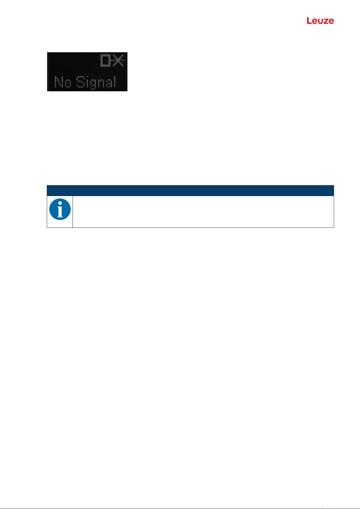
Connecting to a PC – SensorStudio
• No Signal: No measurement value is output
Fig.8.7: Display: No measurement value in the case of deactivation
Input function: Activating/deactivating sensor via switching input
The following options are available:
• Activation: Voltage on the multifunction input activates the sensor
• Deactivation: Voltage on the multifunction input deactivates the sensor
• No function
• Teach
• Trigger rising
• Trigger falling
NOTICE
If you select the Activation or Deactivation input functions, the functions via IO-Link have no effect (Transducer Disable and the associated system commands).
Data storage
The current status of the DSUpload (Data Storage Upload) flag stored in the non-volatile memory of the
sensor is displayed, provided that cyclical updating is active.
The following functions for changing the DSUpload flag are available:
• Set DSUpload Flag: Local configuration changes at the sensor remain saved when an IO-Link master
is connected, and are transferred to the IO-Link master.
• Clear DSUpload Flag: Local configuration changes at the sensor are overwritten when an IO-Link master is connected.
Local configuration lock
This button is used to disable the sensor. Operation via the OLED display and keyboard is only possible after deactivation of the lock via IO-Link or using the configuration software SensorStudio.
Leuze electronic GmbH + Co. KG ODS 9 68
Page 69
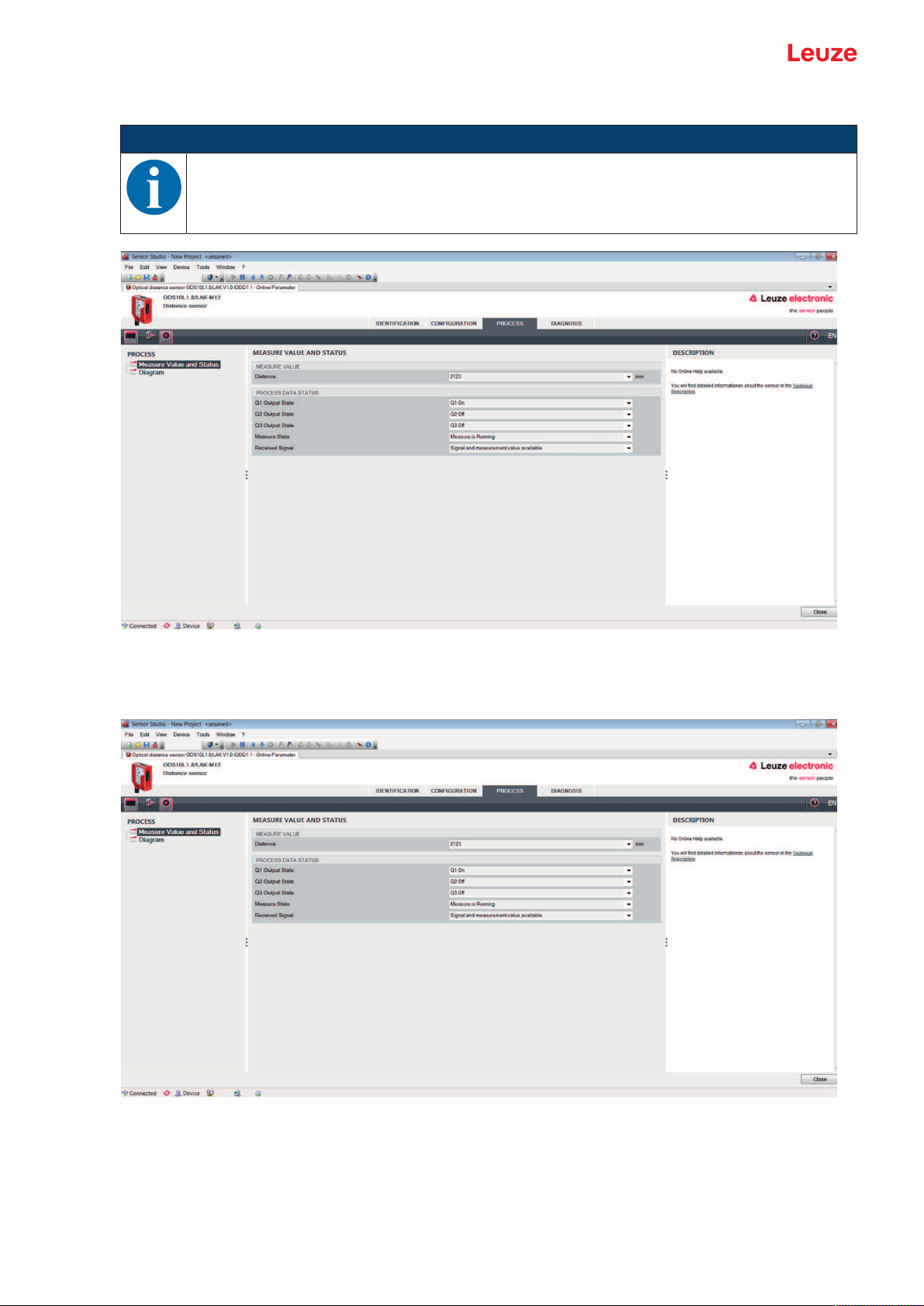
Connecting to a PC – SensorStudio
8.4.4
PROCESS function
NOTICE
The figures show a similar sensor.
Fig.8.8: PROCESS function
• Visualization of the distance value and the states of the digital output signals.
Text-based display of the current values:
Fig.8.9: PROCESS function – distance value and status
Leuze electronic GmbH + Co. KG ODS 9 69
Page 70

Connecting to a PC – SensorStudio
• Graphical display of the recorded measurement values, including the history:
Fig.8.10: PROCESS function – display of the measurement values
Fig.8.11: PROCESS function – display of the measurement values
Leuze electronic GmbH + Co. KG ODS 9 70
Page 71
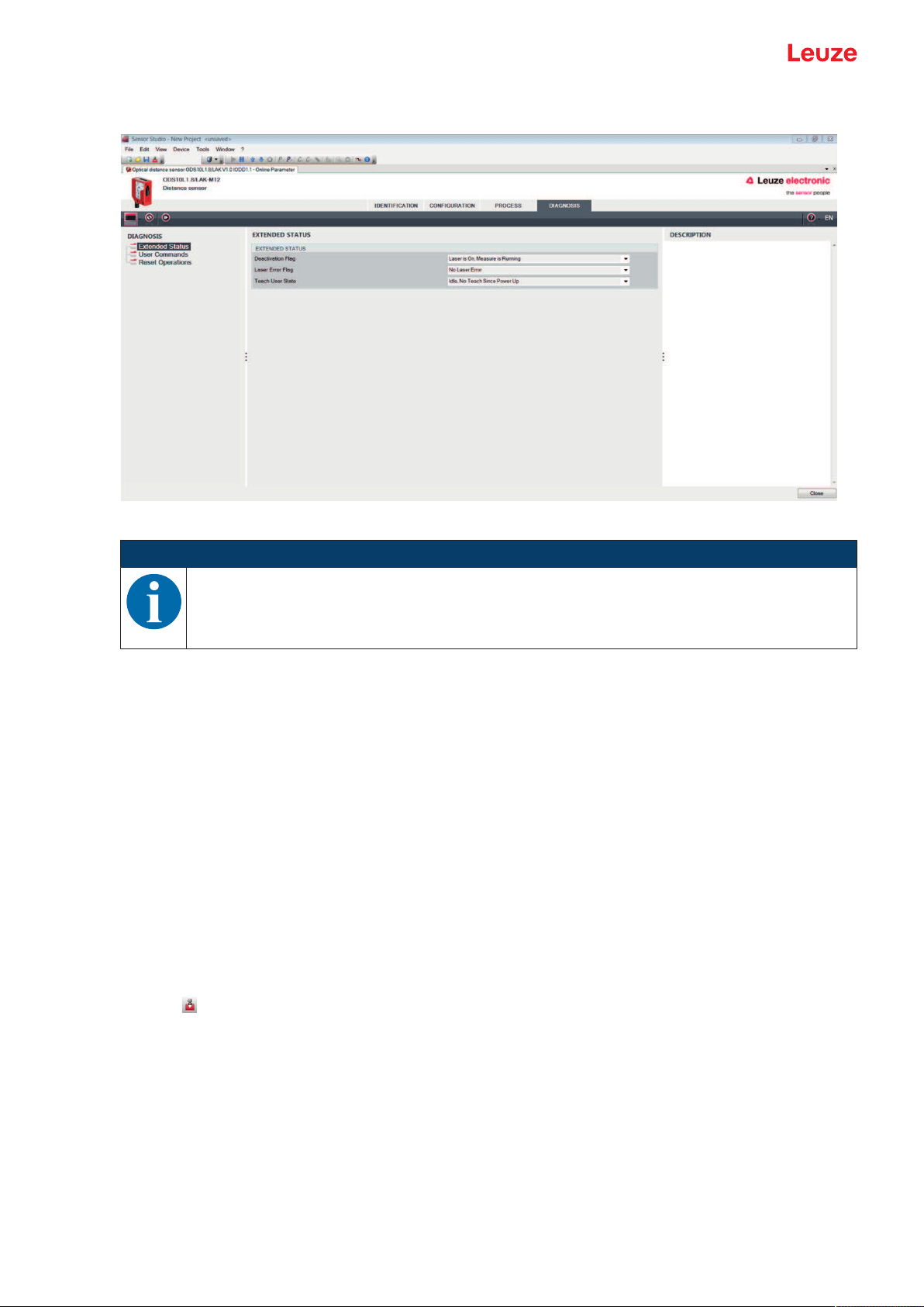
Connecting to a PC – SensorStudio
8.4.5
DIAGNOSIS function
Fig.8.12: DIAGNOSIS function
NOTICE
8.4.6
The figure shows a similar sensor.
• Information on the current device status
• Restart or reset of the device to factory settings
• User commands
• Set or clear the DSUpload flag
Set DSUpload Flag: Local configuration changes at the sensor remain saved when an IO-Link master is connected, and are transferred to the IO-Link master.
Clear DSUpload Flag: Local configuration changes at the sensor are overwritten when an IO-Link
master is connected.
• Activate or deactivate the sensor
Exiting SensorStudio
After completing the configuration settings, close the SensorStudio configuration software.
Ä Exit the program via File > Exit.
Ä Save the configuration settings as a configuration project on the PC.
You can open the configuration project again at later time via File > Open or via the SensorStudio project
wizard ( ).
Leuze electronic GmbH + Co. KG ODS 9 71
Page 72

Troubleshooting
9 Troubleshooting
9.1 What to do in case of failure?
After switching on the sensor, display elements (see chapter 3.3 "Indicators and operational controls") assist in checking the proper function and troubleshooting.
In case of error, you can determine the error from the LEDs and the indicators on the display. With the error
message you can determine the cause of the error and initiate measures to rectify it.
Ä Switch off the system and leave it switched off.
Ä Analyze the cause of the error using the operation indicators, the error messages and with the help of
the SensorStudio configuration software, DIAGNOSTICS menu, and rectify the error.
NOTICE
Contact Leuze subsidiary/customer service.
Ä If you are unable to rectify a fault, contact the Leuze branch responsible for you or call the
Leuze customer service (see chapter 11 "Service and support").
9.2 LED indicators
You can use the LED indicators to ascertain general causes of errors (see chapter 3.3.1 "LED indicators").
Tab.9.1: Green LED – causes and measures
Error display Possible cause Measures
Off • No supply voltage connected to the
sensor
• Hardware error
Tab.9.2: Orange LED – causes and measures
Error display Possible cause Measures
Off No object detected in the switching
range
9.3 Indicators in the display
You can use the status indicators in the display to ascertain general error causes; (see chapter 3.3.3 "Display").
Tab.9.3: Display indicators – causes and measures
Display Possible cause Measures
Warning message, e.g., weak
reception signal
No object detected or reception signal too weak
• Check supply voltage
• Contact Leuze customer service (see
chapter 11 "Service and support")
Position object in the configured switching
range
Optimize object alignment
Position object in the measurement range
Signal failure
Sensor defective
The current measurement
value is less than the lower
limit of the analog output distance
The current measurement
value is greater than the upper
limit of the analog output distance
Leuze electronic GmbH + Co. KG ODS 9 72
If the icon is displayed continuously: contact
Leuze customer service (see chapter 11 "Service and support")
Change the setting for the lower limit of the
measurement range (see chapter 3.4.4 "Analog_Output menu")
Change the setting for the upper limit of the
measurement range (see chapter 3.4.4 "Analog_Output menu")
Page 73

Care, maintenance and disposal
10 Care, maintenance and disposal
10.1 Cleaning
If there is dust on the device:
Ä Clean the device with a soft cloth; use a cleaning agent (commercially available glass cleaner) if neces-
sary.
NOTICE
Do not use aggressive cleaning agents!
Ä Do not use aggressive cleaning agents such as thinner or acetone for cleaning the device.
Use of improper cleaning agents can damage the lens cover.
10.2 Servicing
The device does not normally require any maintenance by the operator.
Repairs to the device must only be carried out by the manufacturer.
Ä For repairs, contact your responsible Leuze subsidiary or Leuze customer service (see chapter 11 "Ser-
vice and support").
10.3 Disposing
Ä For disposal observe the applicable national regulations regarding electronic components.
Leuze electronic GmbH + Co. KG ODS 9 73
Page 74

Service and support
11 Service and support
24-hour on-call service at:
+49 7021 573-0
Service hotline:
+497021573-123
Monday to Friday 8.00a.m. to 5.00p.m. (UTC+1)
E-mail:
service.identify@leuze.de
Repair service and returns:
Procedure and Internet form can be found at
www.leuze.com/repair
Return address for repairs:
Service center
LeuzeelectronicGmbH+Co.KG
InderBraike1
D-73277Owen/Germany
11.1 What to do should servicing be required?
What to do should servicing be required?
NOTICE
Please use this chapter as a master copy should servicing be required!
Ä Enter the contact information and fax this form together with your service order to the fax
number given below.
Customer data (please complete)
Device type:
Serial number:
Firmware:
Display messages
Status of LEDs:
Error description:
Company:
Contact person/department:
Phone (direct dial):
Fax:
Street/No:
ZIP code/City:
Country:
Leuze Service fax number:
+497021 573-199
Leuze electronic GmbH + Co. KG ODS 9 74
Page 75

Technical data
12 Technical data
12.1 Measurement data
Tab.12.1: Measurement ranges
ODS9…-100… 50mm…100mm 6%…90% diffuse reflection
ODS9…-200… 50mm…200mm
ODS9…-450… 50mm…450mm
ODS9…-650… 50mm…650mm
Tab.12.2: Accuracy
Measurement against diffusely reflective objects
Resolution ODS9…-100…
ODS9…-200…
ODS9…-450…
ODS9…-650…
Temperature deviation
(in % of measurement
value)
Accuracy
(in % of measurement
ODS9…-100…
ODS9…-200…
value)
ODS9…-450…
ODS9…-650…
• Diffuse reflection: 6%…90%
• Measure mode: Standard
• At 20°C after warmup time of 20 minutes
0.01mm
0.01mm of 50mm…100mm
0.1mm of 100mm…200mm
0.1mm
0.1mm
≤±0.02%/K
±0.5%
±0.5% of 50mm…100mm
±1% of 100mm…200mm
±1%
±1%
Leuze electronic GmbH + Co. KG ODS 9 75
Page 76
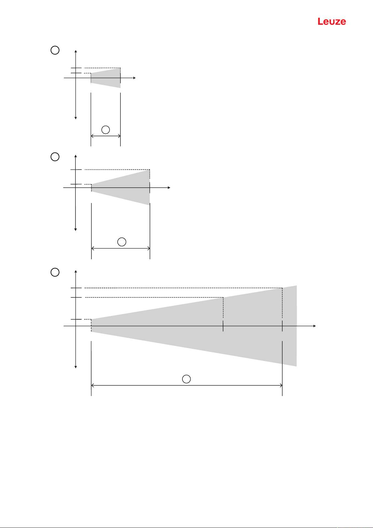
Technical data
PP
PP
PP
D
\
\
[
200 mm
2 mm
0,25 mm
a
y
y
x
6,5 mm
4,5 mm
450 mm 650 mm
0,5 mm
a
y
y
x
1
2
3
x Measurement range
y Maximum measurement error (+/-)
Gray area Permissible measurement deviation
1 Accuracy up to 100mm, a=0.5% of the measurement value
2 Accuracy up to 200mm, a=1% of the measurement value
3 Accuracy up to 450mm and 650mm, a=1% of the measurement value
Fig.12.1: ODS 9 measurement accuracy
Leuze electronic GmbH + Co. KG ODS 9 76
Page 77

Technical data
Reproducibility
• 3sigma: 0.2mm
• Diffuse reflectance: 6%...90%
• At 20°C after warmup time of 20 minutes
12.2 Optical data
Tab.12.3: Optical data
Light source Laser diode
Wavelength 650nm (red, visible)
Pulse duration 22ms
Max. output power (peak) ODS9L1...: 0.78 mW
Light spot approx. 1mmx1mm
ODS9L1: Laser class 1 acc. to IEC 60825-1:2014
ODS9L2: Laser class 2 acc. to IEC 60825-1:2014
ODS9L2...: 1.8 mW
Leuze electronic GmbH + Co. KG ODS 9 77
Page 78

Technical data
12.3 Indicators and operational controls
Tab.12.4: Indicators/operational controls
Display OLED display
Keyboard Two buttons
LEDs on the control panel
12.4 Electrical data
Tab.12.5: Electrical equipment
Operating voltage U
Supply voltage
Residual ripple ≤15% of U
Open-circuit current ≤50mA
Switching output Push-pull switching output
Signal voltage high/low ≥(UB - 2V)/≤2V
Analog output
ODS9L1.8/LA…
PWR: status LED, green
SSC: LED for object detection/switching output, orange
B
18V…30V DC
incl. residual ripple
B
NOTE!
The push-pull switching outputs must not be connected in parallel.
• Voltage
1V…10V / 0V…10V
RL ≥2kΩ
• Current (factory setting)
4mA…20mA, RL ≤500Ω
IO-Link COM3 (230.4kBaud), Vers.1.1
Serial interface
RS232 / RS485
12.5 Mechanical data
Tab.12.6: Mechanical data
Housing Plastic
Optics cover Glass, ODS9Lx.8/xxx.P: plastic
Weight 85g
Connection type M12 connector, turnable by 90°
min. cycle time: 0.5ms
SIO is supported
9,600baud (factory setting, baud rate configurable)
Leuze electronic GmbH + Co. KG ODS 9 78
Page 79

Technical data
12.6 Environmental data
Tab.12.7: Environmental data
Ambient temperature (operation) -20°C…+50°C
Ambient temperature (storage) -30°C…+70°C
Protective circuit Transient protection
VDE protection class III
Polarity reversal protection
Short circuit protection for all outputs
Degree of protection with correctly
IP67
screwed-on M12 connector
Standards applied IEC60947-5-2
Leuze electronic GmbH + Co. KG ODS 9 79
Page 80

Technical data
12.7 Dimensioned drawings
All dimensions in mm
A Reference edge for the measurement
B Optical axis
C M12 connector, turnable by 90°
D Receiver
E Transmitter
F Display
G Yellow LED – switching output state
H Green LED – operating state
J Control buttons
Fig.12.2: Dimensioned drawing ODS9 with M12 connector
Leuze electronic GmbH + Co. KG ODS 9 80
Page 81

Technical data
12.8 Dimensioned drawings: Accessories
all dimensions in mm
Fig.12.3: Dimensioned drawing mounting system BTU300M-D10/D12/D14
all dimensions in mm
Fig.12.4: Dimensioned drawing mounting bracket BT300M.5
Leuze electronic GmbH + Co. KG ODS 9 81
Page 82

Order guide and accessories
13 Order guide and accessories
13.1 Type overview ODS9
Optical distance sensors, measurement against object
NOTICE
The types given in the overview below can change or be supplemented with further models.
NOTICE
If the IO-Link interface is not used, all device models are equipped with a switching output on
pin 4.
Part no. Part designation Description
50137820 ODS9L2.8/LAK-100-M12 100mm max. measurement distance, IO-Link inter-
face, analog output, multifunction input
50137819 ODS9L2.8/LAK-200-M12 200mm max. measurement distance, IO-Link inter-
face, analog output, multifunction input
50137818 ODS9L2.8/LAK-450-M12 450mm max. measurement distance, IO-Link inter-
face, analog output, multifunction input
50137817 ODS9L2.8/LAK-650-M12 650mm max. measurement distance, IO-Link inter-
face, analog output, multifunction input
50137816 ODS9L2.8/LA6-100-M12 100mm max. measurement distance, IO-Link inter-
face, analog output, second multifunction input
50137815 ODS9L2.8/LA6-200-M12 200mm max. measurement distance, IO-Link inter-
face, analog output, second multifunction input
50137813 ODS9L2.8/LA6-450-M12 450mm max. measurement distance, IO-Link inter-
face, analog output, second multifunction input
50136953 ODS9L2.8/LA6-650-M12 650mm max. measurement distance, IO-Link inter-
face, analog output, second multifunction input
50137824 ODS9L2.8/L6X-100-M12 100mm max. measurement distance, IO-Link inter-
face, switching output
50137823 ODS9L2.8/L6X-200-M12 200mm max. measurement distance, IO-Link inter-
face, switching output
50137822 ODS9L2.8/L6X-450-M12 450mm max. measurement distance, IO-Link inter-
face, switching output
50137821 ODS9L2.8/L6X-650-M12 650mm max. measurement distance, IO-Link inter-
face, switching output
50138326 ODS9L2.8/LFH-100-M12 100mm max. measurement distance, IO-Link inter-
face, serial interface RS232
50138327 ODS9L2.8/LFH-450-M12 450mm max. measurement distance, IO-Link inter-
face, serial interface RS232
50138328 ODS9L2.8/LQZ-100-M12 100mm max. measurement distance, IO-Link inter-
face, serial interface RS485
50138329 ODS9L2.8/LQZ-450-M12 450mm max. measurement distance, IO-Link inter-
face, serial interface RS485
50138330 ODS9L2.8/LQZ-650-M12 650mm max. measurement distance, IO-Link inter-
face, serial interface RS485
Leuze electronic GmbH + Co. KG ODS 9 82
Page 83

Order guide and accessories
Part no. Part designation Description
50141322 ODS9L1.8/LAK-450-M12 450mm max. measurement distance, IO-Link inter-
13.2 Accessories – cables and connectors
NOTICE
Ä To avoid electromagnetic interference, use shielded connection cables when using the ana-
log output.
Tab.13.1: Cables and connectors
Part no. Part designation Description
50020501 KD 095-5A M12 connector (cable socket), user-configurable, 5-
50020502 KD 095-5 M12 connector (cable socket), user-configurable, 5-
50132077 KD U-M12-5A-V1-020 Connection cable with M12 connector on one end,
face, switching output
pin, axial
pin, angled
5-pin, M12, axial, length 2m, PVC sheathing
50133842 KD U-M12-5W-V1-020 Connection cable with M12 connector on one end,
5-pin, M12, angled, length 2m, PVC sheathing
50133855 KD S-M12-5A-V1-020 Shielded connection cable with M12 connector on
one end, 5-pin, M12, axial, length 2m, PVC sheathing
50132079 KD U-M12-5A-V1-050 Connection cable with M12 connector on one end,
5-pin, M12, axial, length 5m, PVC sheathing
50133802 KD U-M12-5W-V1-050 Connection cable with M12 connector on one end,
5-pin, M12, angled, length 5m, PVC sheathing
50133856 KD S-M12-5A-V1-050 Shielded connection cable with M12 connector on
one end, 5-pin, M12, axial, length 5m, PVC sheathing
50132080 KD U-M12-5A-V1-100 Connection cable with M12 connector on one end,
5-pin, M12, axial, length 10m, PVC sheathing
50133803 KD U-M12-5W-V1-100 Connection cable with M12 connector on one end,
5-pin, M12, angled, length 10m, PVC sheathing
50133857 KD S-M12-5A-V1-100 Shielded connection cable with M12 connector on
one end, 5-pin, M12, axial, length 10m, PVC
sheathing
50130692 KD U-M12-4W-P1-020 PUR connection cable with M12 connector on one
end, 4-pin, M12, angled, length 2m
Only for devices ODS9…/L6X…
50130728 KD S-M12-4W-P1-020 Shielded PUR connection cable with M12 connector
on one end, 4-pin, M12, angled, length 2m
Only for devices ODS9…/L6X…
50133839 KD U-M12-5A-P1-020 PUR connection cable with M12 connector on one
end, 5-pin, M12, axial, length 2m
50132536 KD U-M12-5W-P1-020 PUR connection cable with M12 connector on one
end, 5-pin, M12, angled, length 2m
50133859 KD S-M12-5A-P1-020 Shielded PUR connection cable with M12 connector
on one end, 5-pin, M12, axial, length 2m
Leuze electronic GmbH + Co. KG ODS 9 83
Page 84

Order guide and accessories
Part no. Part designation Description
50133862 KD S-M12-5W-P1-020 Shielded PUR connection cable with M12 connector
50133841 KD U-M12-5A-P1-050 PUR connection cable with M12 connector on one
50133860 KD S-M12-5W-P1-050 Shielded PUR connection cable with M12 connector
50115049 K-DS M12A-MA-5P-3m-S-PUR PUR connection cable with RS232 to MA2xxi mod-
13.3 Other accessories
Tab.13.2: Other accessories
Part no. Part designation Description
50117251 BTU300M-D14 Mounting system for mounting on rods Ø14 mm
50117252 BTU300M-D12 Mounting system for mounting on rods Ø12 mm
on one end, 5-pin, M12, angled, length 2m
end, 5-pin, M12, axial, length 5m
on one end, 5-pin, M12, axial, length 5m
ular connection units, M12 connector on one end, 5pin, A-coded, axial, 2nd connection JST ZHR, 12pin, length 3m
13.3.1
13.3.2
50117253 BTU300M-D10 Mounting system for mounting on rods Ø10 mm
50118543 BT300M.5 Mounting bracket
Accessories – PC connection
Tab.13.3: Accessories - PC connection configuration
Part no. Part designation Description
IO-Link USB master V2.0
50121098 SET MD12-US2-IL1.1+accessories IO-Link USB master V2.0
Plug-in power supply unit (24V/24W) with international adapters
High-speed USB2.0 connection cable; USB A to
Mini-USB
Data carrier with software, drivers and documentation
50110126 K-DS M12A-M12A-4P-2m-PVC Interconnection cable with M12 connector on both
ends, 4-pin, M12, axial, length 2m, PVC sheathing
Accessories – IO-Link master
Tab.13.4: Accessories – IO-Link master
Part no. Part designation Description
50131482 MD748i-11-42/L5-2222 IO-Link master
Interfaces: PROFINET
50131483 MD248i-12-8K/L4-2R2K
IO-Link master for top-hat rail mounting in switch cabinet
Interfaces: PROFINET
50131484 MD758i-11-42/L5-2222 IO-Link master
Interfaces: EtherNet/IP, Modbus TCP
50131485 MD258i-12-8K/L4-2R2K IO-Link master for top-hat rail mounting in switch
cabinet
Interfaces: EtherNet/IP, Modbus TCP
Leuze electronic GmbH + Co. KG ODS 9 84
Page 85

EC Declaration of Conformity
14 EC Declaration of Conformity
The optical distance sensor systems of the ODS9 series were developed and manufactured in accordance
with the applicable European standards and directives.
The manufacturer of the product, LeuzeelectronicGmbH+Co.KG in D-73277 Owen, possesses a certified quality assurance system in accordance with ISO 9001.
Leuze electronic GmbH + Co. KG ODS 9 85
 Loading...