

10 - 30 V
DC
IEC 60947...
IEC 60947...
Mounting accessories
With M8 connector
With cable
BTU LV463
Part no. 50120869
4-pin connector 4-wire cable
multi funct:- OFF
- Line teach
- Activation input
- Multiplex operation
Details Description of the subfunctions
NOTE: Open lead wires must be connected to a terminal box.
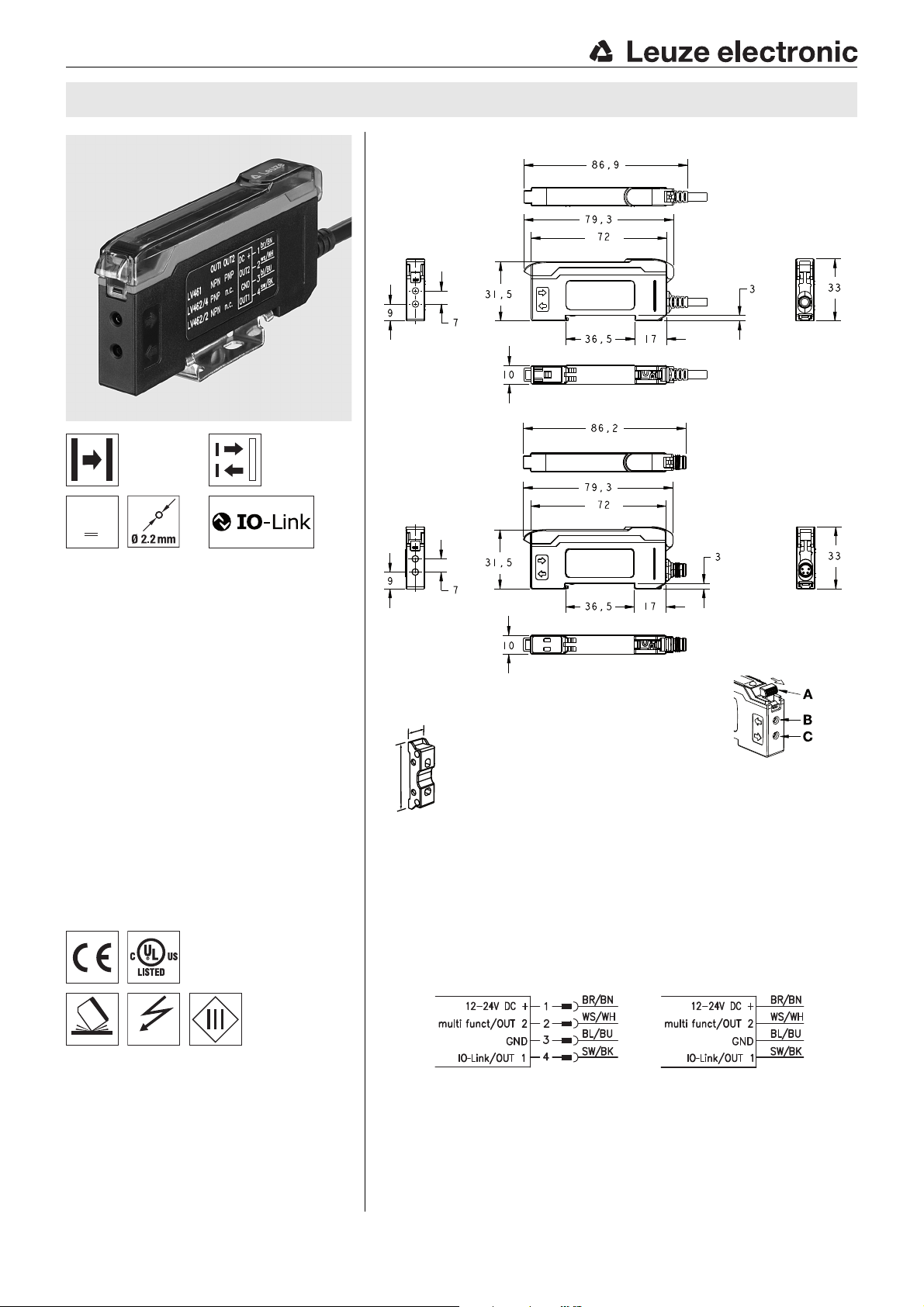
LV463.XR Long Range amplifier with 1 switching output for fiber optics
Dimensioned drawing
en 02-2016/12 50135394
Up to
5000mm
Up to
1350mm
Extra large operating ranges
Two, large, easy-to-read displays for the
simultaneous display of the signal value
and the switching threshold
Simple operation and easy-to-understand
menu functions for optimum configuration
Internal multiplex operation of up to six
units
Line teach or external transmitter activation
Three different teach modes for fast sensor
adjustment
One switching output (PNP or NPN)
Indicator diode for operation and switching
output
Connection via M8 connector, cable or
cable with M12 connector
10
35
A Clamping lever for fiber optic cable (unlock in direction of arrow)
B Connection for fiber optics receiver
C Connection for fiber optics transmitter
Accessories:
(available separately)
Plastic fiber optics (KF, KFX)
Glass fiber optics (GF)
Ready-made cables (KD …)
We reserve the right to make changes • DS_LV463XR1SWO_en_50135394.fm
Mounting device (BTU LV463)
Electrical connection
LV463.XR 1SWO - 02
LV463.XR
Technical data
Optical data Throughbeam
principle
Operating range/scanning range
Light source LED (modulated light)
Wavelength LV463.XR…
1)
LV463I.XR…
Up to 5000mm Up to 1350mm
660nm (visible red light)
880nm (infrared light)
Timing
Readiness delay ≤ 500ms
Internal cycle time 100μs
Signal range
Response time 24ms 8ms 2ms 1000μs 500μs
Switching frequency
Display area (digits) 0 … 9999 0 … 9999 0 … 9999 0 … 9999 0 … 9999
Repeatability 180μs 180μs 180μs 150μs 100μs
Increased protection against optical
crosstalk
Increased protection against ambient
light through energy-saving lamps
Electrical data
Operating voltage UB
Residual ripple ≤ 10% of U
Open-circuit current ≤ 40mA @ 24 VDC
Switching output …/4…
Function Light/dark switching, adjustable by means of a switch
Switching output time functions Switch-on/-off delay,
Adjustable times (time functions) 0 … 9999ms
Signal voltage high/low ≥ (U
Output current ≤ 100mA
Sensitivity Adjustable using the teach function or +/- buttons
2)
3)
…/2…
…/L4… Pin 4/bk: IO-Link SIO mode, Push-pull
Extra Long Range
(XLR)
21Hz 62.5Hz 250Hz 500Hz 1000Hz
Yes Yes Yes Yes No
Yes Yes Yes No No
10 … 24VDC ± 10%
Pin 4/bk: PNP
Pin 4/bk: NPN
Pin 4/bk: IO-Link COM2 mode
Pin 2/wh: PNP dark switching
passing contact (on actuation or fall-back),
(combinations are limited
Combinations of timing functions)
B
Long Range
(LR)
B
(PNP light switching, NPN dark switching)
-2.5V)/≤ 2.5V
Standard
(STD)
Indicators
Yellow LED Switching output active
Display 2 x 7-segment LED, 4-digit,
Red: signal strength,
Green: switching threshold
Mechanical data
Housing ABS/PC black/red, transparent PC cover
Weight 50g with M8 connector,
Connection type M8 connector, 4-pin, or
Fiber optic connection Clamp-mounting, 2 x Ø 2.2mm
63g with 2000mm cable
70g with 150 mm cable and M12 connector
2000mm cable, 4 x 0.25mm
150mm cable with M12 connector, 4-pin
2
, or
Environmental data
Ambient temp. (operation/storage) -10°C … +55°C/-20 °C … +85°C
Protective circuit
Degree of protection IP 50, NEMA 1
Standards applied EN 60947-5-2
Certifications UL 508, C22.2 No.14-13
4)
2, 3
3) 5)
Additional functions
Sensor adjustment Menu-driven using display and rocker push button
1) Range/scanning range depending on the fiber optics used
2) With a duty cycle of 1:1
3) For UL applications: use is permitted exclusively in Class 2 circuits according to NEC
4) 2=polarity reversal protection, 3=short circuit protection for all outputs
5) These proximity switches shall be used with UL Listed Cable assemblies rated 30V, 0.24 A min,
in the field installation, or equivalent (categories: CYJV/CYJV7 or PVVA/PVVA7)
Scanning principle
Speed
(S)
High Speed
(HS)
Notes
NOTE
Detailed specifications on the range/
scanning range are enclosed in the
data sheets of our fiber optics type
KF, KFX or GF.
Explanation of the
signal ranges
Extra Long Range (XLR):
Extra long operating range,
longest response time,
display area 0 … 9999
Long Range (LR)
Long operating range with
good response time;
display area: 0 … 9999
Standard (STD)
Medium operating range and
medium response time;
display area: 0 … 9999
Speed (S)
Short operating range and
short response time;
display area: 0 … 9999
High Speed (HS)
Short operating range,
very short response time;
display area: 0 … 9999
Observe intended use!
This product is not a safety sensor
and is not intended as personnel
protection.
The product may only be put into
operation by competent persons.
Only use the product in accor-
dance with its intended use.
NOTE
A separate data sheet with supplementary information on operation
and configuration via IO-Link is available for the amplifier with IO-Link.
You can find this in the Download
area on the product page of the
amplifier at www.leuze.com.
:
:
:
:
LV463.XR 1SWO - 02 2016/12
LV463.XR Long Range amplifier with 1 switching output for fiber optics
Part number code
LV463 .XR7/ 4T- 150-M12
Operating principle
LV Fiber optic amplifiers
Series
463 463 series
Light source
Not specified Red light
I Infrared light
Design
Not specified Standard design
XV High-speed version
XR Long-range version
Setting
7 Adjustment by means of control panel
Pin assignment of connector pin 4 / black cable wire (IO-Link / OUT1)
4 PNP transistor switching output, light switching
2 NPN transistor switching output, light switching
P PNP transistor switching output, dark switching
N NPN transistor switching output, dark switching
L IO-Link
X Not assigned (n. c.)
(7-segment red/green LED displays, slide switch, rocker push button)
Pin assignment of connector pin 2 / white cable wire (multi funct / OUT2)
T Multifunction input (teach, activation or multiplex operation)
4 PNP transistor switching output, light switching
Connection technology
Not specified Connection cable, standard length 2000mm, 4-wire
M8 M8 connector, 4-pin
150-M8 Cable, length 150mm, with M8 connector, 4-pin
150-M12 Cable, length 150mm, with M12 connector, 4-pin
Order guide
The sensors listed here are preferred types; current information at www.leuze.com
With one switching output and multifunction input With one switching output and IO-Link
Features Order code Part no. Features Order code Part no.
Red light, 1 PNP switching output LV463.XR7/4T-M8 50133974 Red light, 1 PNP switching output LV463.XR7/L4-M8 50134007
Red light, 1 PNP switching output LV463.XR7/4T 50133973 Red light, 1 PNP switching output LV463.XR7/L4 50134008
Red light, 1 PNP switching output LV463.XR7/4T-150-M12 50133975 Red light, 1 PNP switching output LV463.XR7/L4-150-M12 50134009
Red light, 1 NPN switching output LV463.XR7/2T-M8 50133976
Red light, 1 NPN switching output LV463.XR7/2T 50133977
Red light, 1 NPN switching output LV463.XR7/2T-150-M12 50133978
Infrared light, 1 PNP switching output LV463I.XR7/4T 50133995
Infrared light, 1 PNP switching output LV463I.XR7/4T-150-M12 50133996
LV463.XR 1SWO - 02
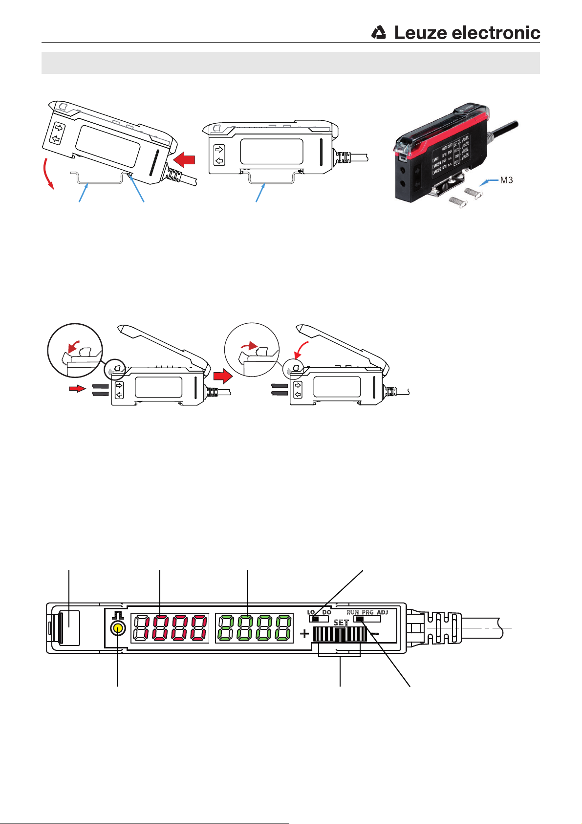
Mounting the amplifier
The amplifier is mounted as shown on a TS 35 DIN rail while disconnected from voltage.
Alternatively, the amplifier can also be
mounted without a DIN rail using the
mounting accessory and M3 screws.
DIN rail TS 35
(35mm x 7.5mm)
DIN rail TS 35
(35mm x 7.5mm)
Spring-mounted
DIN rail mount
①
②
③
④
⑤
Slide switch switching output:
light (LO)/dark (DO) switching
Lever for
fiber optic clamp
Slide switch operating mode:
RUN: Normal operation and IO-Link
PRG: Sensor adjustment
ADJ: Perform teach;
change switching threshold
Rocker push button
+, - and press:
- Changing the switching threshold
- Sensor adjustment
Status LED (yellow)
switching output
7-segment LED display,
4-digit, RED, signal strength
7-segment LED display, 4-digit,
GREEN, switching threshold
Installing the fiber optics
LV463.XR
Open the transparent protective cover.
Push down the lever of the fiber optic clamp to open.
Lead the KF/KFX/GF type fiber optics in completely as far as they will go (ca. 12 mm deep) into the fiber optic intake.
When doing so, observe the transmitter/receiver assignment on the amplifier (transmitter at bottom / receiver on top).
Pull up the lever of the fiber optic clamp to close.
Check if the clamp is secure by pulling lightly on the fiber optics.
Close the transparent protective cover.
Operating and display elements
LV463.XR 1SWO - 02 2016/12

OFF dLY
FctY dEF
ZEro OFSt
Func SEL InP SEL
dISP rEAd
On IShoOFF ISho On dLY
tch SEL1
Auto thr
GAIn SEL
rESP SPd SEnS SEL1
Select
response time
Select
gain
Select
teach mode
Master-slave
assignment
Offset
calibration
Factory setting
Threshold
tracking
Switch-off delay Passing contact
OFF
Start-up delay Passing contact
ON
Turn read
direction 180°
multi funct
input
Sensitivity
switching output
LV463.XR Long Range amplifier with 1 switching output for fiber optics
Selector switch
Operating mode
Selector switch
Switching output
Rocker push button
- Set switching threshold
- Navigation in menu
Indicator
Signal strength
Indicator
Switching threshold
Status LED (yellow)
Switching output state
RUN: Normal operation and IO-Link - no settings possible via the operational controls
ADJ: Press rocker push button: the set teach is executed.
Rock to left - right: change the switching threshold, left = + and right = -.
PRG: Menu-driven device setting via display and rocker push button
LO: Switching output light switching:
If throughbeam fiber optics are installed, the switching output is active when the
light path is free; if a scanning system is installed, the switching output is active
when an object is detected. The status LED illuminates when the switching output
is active.
DO: Switching output dark switching:
The switching behavior is the inversion of the light switching setting.
The rocker push button can be rocked to the right and to the left and pressed
in the middle position.
Rock +, -:In the ADJ operating mode, the switching threshold can be increased (+) or
decreased (-) by rocking. In the PRG operating mode, rock to navigate in the
menu.
Button: Press the rocker push button in the middle position to accept a setting made in
the PRG operating mode.
In the RUN and ADJ operating modes, the display shows the current signal value.
In the PRG operating mode, information on menu navigation appears on the
display.
In the RUN and ADJ operating modes, the display shows the currently set
switching threshold. In the PRG operating mode, information on menu navigation
appears on the display.
LED ON Switching output active.
LED OFF Switching output inactive.
RUN operating mode - normal operation
The RUN operating mode is the standard operating mode in which the sensor detects objects; it signals this according to the set functions. If the selector switch for the operating mode is in the RUN position, no changes to the device
can be made via the operational controls. This setting is thus suitable for protection against unintended operation and
changes to device settings.
For IO-Link operation, the RUN operating mode must be set.
NOTE
The multi funct multifunction input always takes precedence over the Operating mode selector switch.
This means that the amplifier can be taught via the multifunction input (remote teach) in the RUN operating mode as well.
PRG operating mode - sensor adjustment
The LV463 can be adjusted to meet customer requirements with a simple menu-driven system.
To do this, set the selector switch for the operating mode to position PRG.
The menu consists of 14 successive subfunctions. Rock to right or left to freely navigate through the subfunctions.
LV463.XR 1SWO - 02

Selecting a subfunction and changing the setting
f =
1
2
• t
rESP
[Hz]
1.Rock to left or right to select the desired subfunction.
2.Press rocker push button in middle position. The currently set value is displayed statically.
3.Rock to right or left to display the selectable adjustment values - these flash slowly.
4.Accept the new value by pressing the rocker push button in the middle position.
Fast flashing indicates that the new value is accepted.
5.Automatic return to the heading for the subfunction.
6.Press again to statically display the previously selected value.
Description of the subfunctions
LV463.XR
Subfunction Possible settings /
value range
SEnS SEL1
Sensitivity in
switching point OUT1
rESP SPd
Select
response time
Std
hiGh
Lo
t
= 24 ms (signal range XLR)
rESP
8 ms (signal range LR)
2 ms (signal range STD)
1000 μs (signal range S)
500 μs (signal range HS)
Gain stage
t
=24ms:Gn 1 … Gn 7
GAIn SEL
Select
gain
tch SEL1
Select
teach mode OUT1
rESP
8ms:Gn 1 … Gn 6
2ms:Gn 1 … Gn 6
1000μs:Gn 1 … Gn 6
500μs:Gn 1 … Gn 5
Auto
GAIn
Teach modes
1Pt tch (static),
2Pt tch (static),
dYn tch (dynamic)
Auto thr
Threshold
tracking
Tracking the switching threshold
oFF (aus), On (ein)
OFF dLY
Switch-off
delay
0 (off), 1 … 9999 ms (milliseconds) 0
OFF ISho
Passing contact
OFF
0 (off), 1 … 9999 ms (milliseconds) 0
On dLY
Switch-on
delay
0 (off), 1 … 9999 ms (milliseconds) 0
Factory setting
(default)
Std
2 ms
GAIn
Auto
1Pt tch
oFF
Explanation
The sensitivity in the switching point is adjusted via the hysteresis.
High: Small hysteresis, e.g., for exact switching during object positioning.
Std: Standard hysteresis; suitable for most applications.
Lo: Large hysteresis, e.g., for very reliable switching on objects.
Also for applications with strong vibrations on probe.
The response time is the max. time required by the switching output to
switch to the active state following a signal change at the input.
From this, the switching frequency can be calculated as follows:
Notice: A change to the response time is equivalent to a change to the
signal range.
The gain stage can be set either by manually presetting the gain factor or
automatically by selecting Auto GAIn. The left, red display shows the current signal value.
The gain stage should be selected so that the signal value is approximately
in the middle of the display area.
If Auto GAIn is selected, the device automatically determines the optimum
gain setting during teaching.
Presetting a suitable teach process.
To trigger the teach event, see Teaching operating mode.
1-point teach, static: during teaching, the current signal value is accepted
as the new switching threshold. Actuate the rocker push button to make fine
adjustments to the threshold.
2-point teach, static: the switching threshold is calculated at approximately midway between two signal values, e.g., teach to two different
objects or teach to the same object at two different distances from the
probe. Example: signal value 1 = 100digits, signal value 2 = 400digits
Switching threshold = 280 digits. Actuate the rocker push button to + or
- to make fine adjustments to the threshold.
Dynamic teach: suitable for processes that cannot be stopped for teaching.
When the teach event is started, the sensor begins to scan the signal values.
On the left, red display, the signal values are constantly displayed. At the end
of the teach event, the switching threshold is calculated at approximately
midway between the smallest and largest signal value.
The function is only available during dynamic teaching. If the function is
switched on, the switching threshold is automatically and continuously optimized by the sensor in such a way that maximum functional reliability is
ensured.
This can be used to compensate for, e.g., soiling or process changes.
Warning message:
thr ALrt: The limit of threshold tracking is reached - the sensor contin-
Error message:
ues to operate. Cleaning and, if necessary, alignment of the
fiber optics recommended
thr Err: The limit of threshold tracking is exceeded - the sensor
stops operating. Cleaning and, if necessary, alignment of
the fiber optics urgently necessary
Switch-off delay (OFF Delay):
Individually adjustable from 1 … 9999ms.
Combination options Combining timing functions
Passing contact on fall-back (OFF 1-Shot):
Individually adjustable from 1 … 9999ms.
Combination options Combining timing functions
Switch-on delay (ON Delay):
Individually adjustable from 1 … 9999ms.
Combination options Combining timing functions
LV463.XR 1SWO - 02 2016/12

dISP rEAd,
dISP rEAd
LV463.XR Long Range amplifier with 1 switching output for fiber optics
Subfunction Possible settings /
value range
On ISho
Passing contact
ON
0 (off), 1 … 9999 ms (milliseconds) 0
dISP rEAd
Turn read
direction 180°
InP SEL
multi funct
input
oFF,
tch InP,
SYnc PLc,
SYnc Int
SL 1,
SL 2,
SL 3,
Func SEL
Master-slave
assignment
SL 4,
SL 5,
mA 2,
mA 3,
mA 4,
mA 5,
mA 6
ZEro OFSt
Offset
calibration
FctY dEF
Factory
setting
no,
YES
no,
YES
Factory setting
(default)
dISP rEAd
(same read direction as
other texts)
oFF
1
SL
no
no
Explanation
Passing contact on actuation (ON 1-Shot):
Individually adjustable from 1 … 9999ms.
Combination options Combining timing functions
Changes the read direction of the two 7-segment displays by 180º.
With the setting, you define the function of the multi funct multifunction
input (pin 2/ws-WH).
oFF: Pin/cable without function
tch InP: Pin/cable can be used as teach input for line teach or for
SYnc PLc: Pin/cable can be used as activation input. Further details on
SYnc Int: Setting for multiplex operation of up to 6 fiber optic amplifi-
These settings only need to be made if multiplex operation (master-slave
operation) of multiple sensors is desired.
A maximum of 6 sensors can be synchronized with one another in multiplex
operation.
Here, exactly one master and 1…5 slaves are always needed.
Settings for master:
mA n (number):
Example:
remote configuration. Further details on this topic
Line teach / remote teach.
Remote configuration special function.
this topic
Synchronous operation of multiple amplifiers.
ers. For this purpose, all multi funct multifunction inputs
(pin 2/ws-WH) are connected to one another. The master unit
(defined with the next subfunction) generates a timing signal
that is received by the slave units (defined with the next subfunction) via the parallel connection. In a fixed time frame,
each slave successively activates its transmitter for a brief
time and delivers a signal value. To avoid mutual interference, the transmitter is then deactivated again.
Further details on this topic
Multiplex operation of multiple amplifiers.
Defines that this unit functions as a master and a total of n
sensors were wired in parallel.
Value range n = 2 … 6.
mA 4means: unit is the master, a total of 4 sensors are wired to one
another via the multi funct multifunction input.
Setting for slaves:
SL n (number):
Defines that this unit functions as a slave and has individual
address n.
Example:
Value range address n = 1 … 5.
SL 3 means: unit is aslave with individual address 3.
Further details on this topic Multiplex operation of multiple amplifiers
This subfunction is used for suppressing an offset signal that can result,
e.g., from crosstalk between transmitter and receiver at the fiber optic head.
To activate this function, select YES and confirm the selection by pressing
the rocker push button. The current signal value is now set to 0.
To perform another offset calibration, the previous calibration must first be
reset. To do this, select no and confirm by pressing the rocker push button.
Now again perform the offset calibration as previously described.
Note: Resolution is lost when using offset suppression!
Attention!
Resets all sensor settings to factory settings.
If desired, select YES and execute by pressing the rocker push button.
Example: display area = 4000 digits, offset value = 550digits
Remaining resolution = 3450digits
Tip!
The maximum operating range can be achieved as follows:
rESP SPd to 24 ms (signal range XLR).
-Set
GAIn SEL to the highest gain stage.
-Set
- The switching threshold can be set to minimum 32 digits,
the amplifier detects objects up to display value 0.
LV463.XR 1SWO - 02

Time functions
ON DLY
ON DLY
ON 1Shot
ON 1Shot
OFF 1Shot
OFF 1Shot
OFF DLY
OFF DLY
T T T
T T T
T T T
T T T
T T
T
T
T T T
T
T
Switching threshold
Time t
Time t
Signal
OUT
Switching threshold
Time t
Time t
Signal
OUT
Switching threshold
Time t
Time t
Signal
OUT
Switching threshold
Time t
Time t
Signal
OUT
Switching threshold
Time t
Time t
Signal
OUT
Switching threshold
Time t
Time t
Signal
OUT
Switching threshold
Time t
Time t
Signal
OUT
Switching threshold
Time t
Time t
Signal
OUT
Rising edge
Falling edge
Active state of the switching output
Set delay time
(0 … 9999ms)
LV463.XR
LV463.XR 1SWO - 02 2016/12

LV463.XR Long Range amplifier with 1 switching output for fiber optics
Combining timing functions
Timing functions can only be combined to a limited extent. Impermissible combinations are suppressed from the subfunctions menu.
Here is an overview of the permissible combinations (•):
OFF dLY
Switch-off
delay
OFF ISho
Passing contact
OFF
OFF dLY
Switch-off
delay
••
OFF ISho
Passing contact
OFF
•
On dLY
Switch-on
delay
• •
On ISho
Passing contact
ON
Teaching operating mode
Set the selector switch for the operating mode to the ADJ position.
Depending on the setting of the Select teach mode subfunction (
appears:
Static 1-point teach
Static 2-point teach
Dynamic teach
Teach process
Step
Static 1-point teach Static 2-point teach Dynamic teach
On dLY
Switch-on
delay
On ISho
Passing contact
ON
•
tch SEL1), one of the following teach modes
Place object in light beam.
The red display shows the signal value, the green dis-
play the current switching threshold.
Press the rocker push button; the teach value is
accepted.
Place object in light beam.
The red display shows the signal value, the green display the current switching threshold.
Press the rocker push button, first teach value is
accepted.
Press the rocker push button. The green display
dYn, the red display the current signal value.
shows
The amplifier now scans signal values for approx. 1
minute.
Move several objects through the light beam; to end
the event, press the rocker push button again.
After the scanning time elapses, the teach event ends
automatically.
2nd appears on the green display; the red display
shows the current signal value.
Place object 2 or object at distance 2 and press the
rocker push button within one minute. The second
Following a successful teach, PASS appears on the
green display and the signal value is displayed as the
new switching threshold.
In the event of a faulty teach,
display. In this case, the signal value may be too small
and cannot be accepted as a teach value (
with minimum teach values as a function of the
setting).
Check object and/or placement and repeat event.
The switching threshold can be freely increased or
decreased at a later time by rocking the rocker push
button to the left (+) and right (-).
The change is accepted if both displays flash briefly
several times.
Tip!
For reliable function, the difference between the signal value while an object is present and the signal value with no object should be at
least 10 … 20%. In general: the larger the difference, the more reliable the detection.
FAIL appears on the red
Tab le
teach value is accepted.
If the rocker push button is not pressed within one
minute, the teach event is interrupted and the previous switching threshold is retained.
Following a successful teach,
green display. The new switching threshold now lies
approximately midway between the two taught signal
values.
In the event of a faulty teach,
display. In this case, the minimum distance between
the two teach points may be too small ( Tab le with
minimum teach values as a function of the setting).
Try to set a larger distance between the two signal values and repeat the event.
The switching threshold can be freely increased or
decreased at a later time by rocking the rocker push
button to the left (+) and right (-).
The change is accepted if both displays flash briefly
several times.
PASS appears on the
FAIL appears on the red
Following a successful teach,
green display. The new switching threshold now lies
between the maximum and the minimum of the
scanned signal values.
In the event of a faulty teach,
display. In this case, the minimum distance between
the scanned signal values may be too small (
with minimum teach values as a function of the
setting).
Try to set a larger distance between the signal values
and repeat the event.
The switching threshold can be freely increased or
decreased at a later time by rocking the rocker push
button to the left (+) and right (-).
The change is accepted if both displays flash briefly
several times.
PASS appears on the
FAIL appears on the red
Tab le
LV463.XR 1SWO - 02

Line teach (remote teach)
LOW
t
HIGH
≥ 20ms 20 … 80ms 900 … ∞ms > 900ms > 500 ms
Before teaching:
---LOW level =
selector switch Operating
mode unlocked
––––– HIGH level =
selector switch Operating
mode locked
A signal change is only necessary if
a HIGH signal is applied prior to the teach.
Action begins with
the rising edge:
t
Tea ch
=
20 … 80ms
Operating mode
selector switch
locked
The teach event begins with the falling edge.
1. Static 1-point teach:
The current signal value is taken
over as the teach value with the
falling edge.
2. Static 2-point teach:
The current signal value is taken
over as teach value 1 with the
falling edge.
3. Dynamic teach:
The sensor begins to scan the
signal values with the falling edge
Note: The sensor remains in teach
mode without timeout until the next
rising edge.
The teach event is ended with the
rising edge:
1. Static 1-point teach:
No further action
2. Static 2-point teach:
The current signal value is taken
over as teach value 2 with the
rising edge.
3. Dynamic teach:
Scanning of the signal values
ends with the rising edge.
The teach event ends 900 ms after
the rising edge, and the sensor
again operates in normal operation.
If the Operating mode selector
switch is to be operable again, a
LOW signal must be applied. The
switch can again be operated 500
ms after the falling edge.
Notes:
• The display on the two displays during the line teach
corresponds to the description for the manual teach.
• The line teach begins with
the rising edge at the teach
input independent of the
position of the Operating
mode selector switch.
Operating mode selector switch locked
Teach time
Activation of the
teach event
t = 20 … 80ms
Subfunction setting:
LV463.XR
InP SEL
multi funct
input
tch InP
Teach
input
Signal level at multi funct teach input:
The following description applies to PNP switching logic!
With the NPN models, the signal levels are inverted!
Timing for the line teach
Which line teach is performed is set in the Select teach mode tch SEL1 subfunction.
Depending on the setting, this may be a static 1-point teach, a static 2-point teach or a dynamic teach.
Locking the amplifier via the teach input
A static HIGH signal ( ≥ 20ms) on the teach input locks the Operating mode selector switch independent of its position. No manual
configuration or adjustment can be performed (e.g., protection against erroneous operation or manipulation).
If the teach input is not connected or if a static LOW signal is applied, the Operating mode selector switch is unlocked and all func-
tions can be accessed as described.
LV463.XR 1SWO - 02 2016/12

LV463.XR Long Range amplifier with 1 switching output for fiber optics
Special function: Remote configuration
In addition to the described line teach, a simple pulse-pause signal at the teach input can be used to perform a partial configuration of
the device. To do this, make this setting in the submenu:
InP SEL
multi funct
input
tch InP
Teach
input
NOTE
For the pulse sequences described in the following for device configuration via the teach input, the following conventions apply:
• Signal level: The description applies for PNP devices (active high). For NPN devices (active low), the pulse sequences are to be inverted accordingly.
• Pulse length T: HIGH and LOW pulses are the same length: 0.04 s < T < 0.8s.
• Pause length P: The following applies for the pauses between the pulse sequences: P > 1s.
Settings for switching output OUT1
TPTTTTTPT
TPTTTTTPTTT
TPTTTTTPTTTTT
TPTTTTTTTPT
TPTTTTTTTPTTT
Te ach mo d e O U T 1
Switching function OUT1
1-point teach
2-point teach
Dynamic teach
Light switching
Dark switching
Setting the response time and the gain
Response time 500 μs
Response time 1000μs
TTTPTTTPT
TTTPTTTPTTT
Select response time
Select gain
1) Not adjustable for response time 500 μs
2) Not adjustable for response times 500 μs, 1000 μs, 2ms and 8 ms
Response time 2 ms
Response time 8 ms
Response time 24ms
Auto GAIn
Gn1
Gn2
Gn3
Gn4
Gn5
Gn6
Gn7 TTTPTPTTTTTTTTTTTTTTT
TTTPTTTPTTTTT
TTTPTTTPTTTTTTT
TTTPTTTPTTTTTTTTT
TTTPTPT
TTTPTPTTT
TTTPTPTTTTT
TTTPTPTTTTTTT
TTTPTPTTTTTTTTT
TTTPTPTTTTTTTTTTT
TTTPTPTTTTTTTTTTTTT
1)
2)
LV463.XR 1SWO - 02

SlavesSlaves Master
All multi funct multifunction inputs
(pin 2/ws-WH) are connected in parallel
For settings, see subfunctions:
Maximum 6 / minimum 2 units: 1 x master + 1 … 5 slaves.
Each unit can be either a master (mA or slave (SL).
The master also requires the information on the number of units connected in
parallel (
n = 1 + number of slaves).
Each slave also receives an individual address 1 … 5 (max.)
The master generates a timing signal on pin 2 or on cable ws/WH.
Each slave switches on its transmitter for 1 ms depending on its address.
In multiplex operation, the cycle time is based on the total number of units:
cycle time = number of units • 1.5ms + 0.5ms.
InP SEL
multi funct
input
SYnc Int
Multiplex operation
Func SEL
Master-slave
assignment
mA n
Master assignment
SL 1… SL 5
Slave assignment
multi funct
activation input
(pin 2/ws-WH)
Transmitter
OFF
Transmitter
OFF
Transmitter
ON
The transmitter is deactivated with a high
signal. The transmitter is activated without
actuation or with a low signal.
LV463.XR
Multiplex operation of multiple amplifiers
If multiple light axes are arranged immediately adjacent to one another, mutual interference may occur, recognizable by a strongly fluctuating display.
To avoid this undesirable behavior, up to 6 devices can operate in multiplex operation. To do this, it is only necessary to connect the
multi funct multifunction input (pin 2/ws-WH) of all participating amplifiers in addition to the voltage supply and switching signal.
Synchronous operation of multiple amplifiers / operation with activation input
If may also be necessary to query multiple light axes simultaneously (synchronously) . There are two ways to do this:
Model 1:
Wiring and adjustment according to section Multiplex operation of multiple amplifiers, but all slaves receive an identical address
from 1 … 5. Result: Master and slaves have a time offset of 1.5 ms; slaves with the same address operate synchronously.
Model 2:
Synchronous operation through an external activation signal at the multi funct input (pin 2/ws-WH). Subfunction setting:
InP SEL
multi funct
input
Function:
LV463.XR 1SWO - 02 2016/12
SYnc PLc
activation
input
 Loading...