

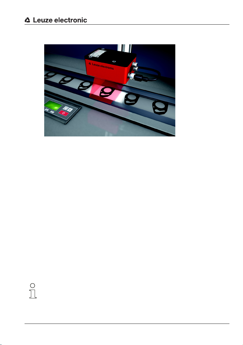
LSIS 4xxi
Smart Camera
EN 06-2018/01 50110628
We reserve the right to
make technical changes
Original operating instructions

LSIS 4xxi
Navigate
upward/laterally
Navigate
downward/laterally
ESCAPE
leave
ENTER
confirm
Device buttons:
Delete digit
Enter digit
Save input
The main menus
ESC
Input of values
12|
<-|0123456789 save
Standard ----- Unit
126 | |
LSIS 400i
Leuze electronic
GmbH + Co. KG
SW: V 2.2.1 HW: V 01.09
SN: 0508A123456 001
IO1 IO2 IO3 IO4 RS232
IO5 IO6 IO7 IO8 ETH 100
ATT ERR TMP
OK
Stat isti cs
Counter state
Tested: 0
OK: 0
NOK: 0
Parameter
Parameter handling
Display settings
Program selection
Ethernet
Language
o Deutsch
o English
o Español
o Français
o Italiano
Device information - main menu
Information about
• Device type
• Software version
• Hardware version
• Serial number
Status displays - main menu
• Status displays of the switching inputs/
outputs
• Display of warnings and errors
• Status information for the device interfaces
• Optional: check program-specific display
See "Indicators in the display" on page 40.
Statistics - main menu
Statistics data for the smart camera.
See "Statistics" on page 44.
Parameter - main menu
Editing Ethernet settings and selecting
check programs stored on the LSIS 4xxi.
See "Parameter menu" on page 45.
Language selection - main menu
Selection of the display language.
See "Language selection menu" on
page 46.
PWR LED BUS LED
Off Device OFF Off No supply voltage
Flashes green Device ok, initialization phase Flashes green Bus initialization
Green, continuous light Device OK Green, continuous light Operation OK
Orange, continuous light Service mode
Flashes red Device ok, warning set Flashes red Communication error
Red, continuous light Device error
Ser vi ce
Status messages
Service - main menu
Camera diagnosis and status messages.
See "Service menu" on page 46.

Table of contents
1 General information........................................................................................... 6
1.1 Explanation of symbols..................................................................................................... 6
1.2 Declaration of conformity ................................................................................................. 6
2 Safety .................................................................................................................. 7
2.1 Intended use ....................................................................................................................... 7
2.2 Foreseeable misuse...........................................................................................................8
2.3 Competent persons ........................................................................................................... 9
2.4 Exemption of liability ......................................................................................................... 9
3 Device description........................................................................................... 10
3.1 About smart cameras of the LSIS 4xxi series ...............................................................10
3.2 Characteristics of the smart cameras of the LSIS 4xxi series..................................... 14
3.3 Device construction......................................................................................................... 16
3.4 Stand-alone connection .................................................................................................. 17
4 Installation and mounting ............................................................................... 18
4.1 Storage, transportation ................................................................................................... 18
4.2 Mounting the LSIS 4xxi ................................................................................................... 19
4.2.1 Fastening with M4 x 6 screws......................................................................................................19
4.2.2 Mounting devices.........................................................................................................................20
4.3 Device arrangement......................................................................................................... 22
4.3.1 Selecting a mounting location......................................................................................................22
4.3.2 Determining the camera distance................................................................................................22
4.4 Lens replacement LSIS 4xxi - C-mount devices ........................................................... 25
4.5 Exchange / Mounting of optical filters ........................................................................... 26
4.5.1 Mounting of optional polarization filter on standard device..........................................................26
4.5.2 Filter exchange for C-mount device............................................................................................. 27
4.6 Cleaning............................................................................................................................ 28
5 Electrical connection....................................................................................... 29
5.1 Safety notices for the electrical connection.................................................................. 30
5.2 Electrical connection of the LSIS 4x2i ...........................................................................31
5.2.1 PWR - voltage supply and switching inputs/outputs 1 to 4..........................................................32
5.2.2 BUS OUT - RS 232 and switching inputs/outputs 5 to 8 ............................................................. 34
5.2.3 SERVICE - Ethernet host/configuration interface........................................................................ 35
Leuze electronic LSIS 4xxi 1

Table of contents
6 Commissioning and configuration................................................................. 36
6.1 Establishing a connection between PC and LSIS 4xxi ................................................. 36
6.1.1 Starting the device.......................................................................................................................36
6.1.2 Establishing an Ethernet connection ...........................................................................................36
6.1.3 Configuring the LSIS 4xxi from a laptop without a network.........................................................37
6.1.4 Integrating the LSIS 4xxi in an existing network..........................................................................38
6.2 Configuring via webConfig ............................................................................................. 39
7 Display and control panel ............................................................................... 41
7.1 Structure of the control panel......................................................................................... 41
7.2 Status display and operation .......................................................................................... 41
7.2.1 Indicators in the display ............................................................................................................... 41
7.2.2 Control buttons ............................................................................................................................42
7.2.3 LED status displays ..................................................................................................................... 43
7.3 Menu description .............................................................................................................44
7.3.1 The main menus ..........................................................................................................................44
7.3.2 Status displays............................................................................................................................. 45
7.3.3 Statistics ......................................................................................................................................45
7.3.4 Parameter menu..........................................................................................................................46
7.3.5 Language selection menu............................................................................................................47
7.3.6 Service menu...............................................................................................................................47
7.4 Operation .......................................................................................................................... 48
8 Diagnostics and troubleshooting................................................................... 51
8.1 Error signaling via LED ................................................................................................... 51
9 Type overview and accessories ..................................................................... 52
9.1 Type overview LSIS 4xxi - standard devices................................................................. 52
9.2 Type overview LSIS 4xxi - C-mount devices and lenses.............................................. 53
9.3 Accessories...................................................................................................................... 53
9.4 Accessory ready-made cables for voltage supply........................................................ 54
9.4.1 Contact assignment of PWR connection cable............................................................................54
9.4.2 Order codes of the cables for voltage supply ..............................................................................54
9.5 Accessory ready-made cables for bus connection ......................................................55
9.5.1 Contact assignment BUS OUT connection cable........................................................................ 55
9.5.2 Order codes BUS OUT connection cables..................................................................................55
Leuze electronic LSIS 4xxi 2

Table of contents
9.6 Accessories for the host/service interface.................................................................... 56
9.6.1 Ready-made cables with M12 plug/open cable end....................................................................56
9.6.2 Ready-made cables with M12 plug/RJ-45 plug........................................................................... 57
9.6.3 Ready-made cables with M12 plug/M12 plug ............................................................................. 58
9.6.4 Connector .................................................................................................................................... 58
10 Maintenance ..................................................................................................... 59
10.1 General maintenance information .................................................................................. 59
10.2 Repairs, servicing ............................................................................................................ 59
10.3 Disassembling, packing, disposing ...............................................................................59
11 Specifications .................................................................................................. 60
11.1 Specifications of standard devices with integrated lens ............................................. 60
11.2 Specifications of devices for C-mount interchangeable lenses .................................. 61
11.3 Dimensioned drawings.................................................................................................... 62
Leuze electronic LSIS 4xxi 3

Figures and tables
Figure 3.1: Application example: presence monitoring ......................................................................... 11
Figure 3.2: Application example: completeness monitoring .................................................................. 11
Figure 3.3: Application example: orientation detection.......................................................................... 12
Figure 3.4: Application example: code verification ................................................................................ 12
Figure 3.5: Application example: dot-peened Data Matrix code............................................................ 13
Figure 3.6: Application example: label positioning and label identification............................................ 13
Figure 3.7: Application example - measurement of radii and roundness .............................................. 14
Figure 3.8: Detecting objects with webConfig ....................................................................................... 15
Figure 3.9: Standard device construction.............................................................................................. 16
Figure 3.10: Device construction variants for C-mount interchangeable lens ......................................... 16
Figure 3.11: Stand-alone connection ...................................................................................................... 17
Figure 4.1: Device name plate LSIS 4xx
Figure 4.2: Fastening options using M4 threaded holes ....................................................................... 19
Figure 4.3: BT 56 mounting device ....................................................................................................... 20
Figure 4.4: Mounting examples of LSIS 4xx
Figure 4.5: BT 59 mounting device ....................................................................................................... 21
Figure 4.6: Camera distance / image field - standard devices .............................................................. 23
Figure 4.7: Camera distance / image field - device models for C-mount interchangeable lenses ........ 24
Figure 4.8: Lens replacement for C-mount devices .............................................................................. 25
Figure 4.9: Optional polarization filter for standard devices .................................................................. 26
Figure 4.10: Filter replacement for C-mount devices ..............................................................................27
Figure 5.1: Location of the electrical connections ................................................................................. 29
Figure 5.2: Connections of the LSIS 4x2
Table 5.1: Pin assignments - PWR ...................................................................................................... 32
Figure 5.3: Connection diagram of IO1 through IO8 configured as switching inputs ............................33
Figure 5.4: Connection diagram of IO1 through IO8 configured as switching outputs ..........................33
Table 5.2: Pin assignment BUS OUT................................................................................................... 34
Figure 5.5: RS 232 pin assignments ..................................................................................................... 34
Table 5.3: SERVICE pin assignments ................................................................................................. 35
Figure 5.6: Cable assignments - SERVICE on RJ-45........................................................................... 35
Table 6.1: Address assignment in the Ethernet ................................................................................... 37
Figure 6.1: Connecting the LSIS 4xx
Figure 6.2: webConfig start page .......................................................................................................... 39
Figure 7.1: Structure of the control panel .............................................................................................. 41
Table 7.1: Parameter handling submenu ............................................................................................. 46
Table 7.2: Program selection submenu ............................................................................................... 46
Table 7.3: Ethernet submenu............................................................................................................... 47
Table 8.1: General causes of errors..................................................................................................... 51
Table 9.1: Type overview LSIS 4xx
Table 9.2: Type overview LSIS 4xx
Table 9.3: Type overview LSIS 4xx
Table 9.4: Accessories for the LSIS 4xx
Table 9.5: Pin assignments KD S-M12-8A-P1-… ................................................................................ 54
Table 9.6: PWR cables for the LSIS 4xx
Table 9.7: Pin assignments KS S-M12-8A-P1-… ................................................................................55
Table 9.8: BUS OUT cables for the LSIS 4xx
Table 9.9: Ethernet connection cables featuring M 12 plug/open cable end ........................................ 56
i.............................................................................................. 18
i with BT 56 ...................................................................... 21
i ............................................................................................. 31
i to the PC ................................................................................... 38
i - standard devices ...................................................................... 52
i - C-mount devices ...................................................................... 53
i - C-mount lenses ........................................................................ 53
i ............................................................................................. 53
i............................................................................................. 54
i ..................................................................................... 55
Leuze electronic LSIS 4xxi 4

Figures and tables
Table 9.10: Ethernet connection cables M 12 connector/RJ-45 ............................................................. 57
Table 9.11: Ethernet connection cables featuring M 12 plug/M 12 plug ................................................. 58
Table 9.12: Connectors for the LSIS 4xx
Table 11.1: Specifications of the LSIS 4x2
Table 11.2: Specifications of smart camera LSIS 4x2
Figure 11.1: Dimensioned drawing of the LSIS 4xx
Figure 11.2: Dimensioned drawing of the LSIS 4xx
i .............................................................................................. 58
i M4x-…1(-01) smart camera .............................................. 60
i M49-X9............................................................. 61
i smart camera - standard devices.......................... 62
i smart camera - devices for C-mount lenses .........63
Leuze electronic LSIS 4xxi 5
1 General information
1.1 Explanation of symbols
The symbols used in this technical description are explained below.
Attention!
This symbol precedes text messages which must strictly be observed. Failure to comply with
this information results in injuries to persons or damage to the equipment.
Notice!
This symbol indicates text passages containing important information.
1.2 Declaration of conformity
The smart cameras of the LSIS 4xxi series have been developed and manufactured in
accordance with the applicable European standards and directives.
Notice!
You can request a copy of the Declaration of Conformity for the device from the
manufacturer.
General information
The manufacturer of the product, Leuze electronic GmbH & Co KG in D-73277 Owen,
possesses a certified quality assurance system in accordance with ISO 9001.
Leuze electronic LSIS 4xxi 6
TNT 35/7-24V
2Safety
This sensor was developed, manufactured and tested in line with the applicable safety standards. It corresponds to the state of the art.
2.1 Intended use
Smart cameras of the LSIS 4xxi series are designed for general applications in industrial
image processing, e.g. in automation technology or quality assurance.
Areas of application
Smart cameras of the LSIS 4xxi series are designed for the following area of application:
• Presence monitoring
• Completeness monitoring
• Omnidirectional 1D and 2D (multiple) code reading
• Code qualification acc. to ISO/IEC
• Type detection
• Position detection
• Orientation detection
• Measuring tasks
CAUTION
Observe intended use!
The protection of personnel and the device cannot be guaranteed if the device is operated in a manner not complying with its intended use.
Only operate the device in accordance with its intended use.
Leuze electronic GmbH + Co. KG is not liable for damages caused by improper use.
Read the supplement and these operating instructions for the device before commis-
sioning the device. Knowledge of these documents is required in order to use the
equipment for its intended purpose.
Safety
TNT 35/7-24V
Leuze electronic LSIS 4xxi 7
NOTE
Smart cameras from the LSIS 4xxi family correspond to the following classification
regarding integrated illumination:
Illumination white / RGBW:
risk group 1 in acc. with EN 62471:2008.
Illumination infrared:
risk group 0 (exempt group) in acc. with EN 62471:2008.
Illuminations of the free groups do not pose any photobiological danger.
Illuminations in risk group 1 are safe under most conditions of use, except in the case of
very long exposure including possible eye exposure.
To completely prevent indirect dangers, such as glare, do not look directly into the
light.
NOTE
Comply with conditions and regulations!
Observe the locally applicable legal regulations and the rules of the employer's liability
insurance association.
2.2 Foreseeable misuse
Any use other than that defined under "Intended use" or which goes beyond that use is
considered improper use.
In particular, use of the device is not permitted in the following cases:
• in rooms with explosive atmospheres
• as stand-alone safety component in accordance with the machinery directive
• for medical purposes
• in outdoor areas
NOTE
Do not modify or otherwise interfere with the device!
Do not carry out modifications or otherwise interfere with the device.
The device must not be tampered with and must not be changed in any way.
The device must not be opened. There are no user-serviceable parts inside.
Repairs must only be performed by Leuze electronic GmbH + Co. KG.
Safety
1.)
TNT 35/7-24V
1.) Use as a safety-related component within a safety function is not permissible.
Leuze electronic LSIS 4xxi 8

2.3 Competent persons
Connection, mounting, commissioning and adjustment of the device must only be carried
out by competent persons.
Prerequisites for competent persons:
• They have a suitable technical education.
• They are familiar with the rules and regulations for occupational safety and safety at
work.
• They are familiar with the original operating instructions of the device.
• They have been instructed by the responsible person on the mounting and operation
of the device.
Certified electricians
Electrical work must be carried out by a certified electrician.
Due to their technical training, knowledge and experience as well as their familiarity with
relevant standards and regulations, certified electricians are able to perform work on electrical systems and independently detect possible dangers.
In Germany, certified electricians must fulfill the requirements of DGUV regulation 3 (e.g.
electrician foreman). In other countries, there are respective regulations that must be
observed.
2.4 Exemption of liability
Leuze electronic GmbH + Co. KG is not liable in the following cases:
• The device is not being used properly.
• Reasonably foreseeable misuse is not taken into account.
• Mounting and electrical connection are not properly performed.
• Changes (e.g., constructional) are made to the device.
Safety
Leuze electronic LSIS 4xxi 9
TNT 35/7-24V
3 Device description
3.1 About smart cameras of the LSIS 4xxi series
Smart cameras of the LSIS 4xxi series perform numerous tasks in industrial image
processing such as:
• Presence monitoring
• Completeness monitoring
• Omnidirectional 1D and 2D (multiple) code reading
• Code qualification acc. to ISO/IEC
• Type detection
• Position detection
• Orientation detection
• Measuring tasks
The many possible configurations of the device allow it to be adapted to a multitude of detection tasks.
Functions overview
There are 3 basic device types available with various performance characteristics:
Features LSIS 412i … LSIS 422i … LSIS 462i …
BLOB analysis
Presence / completeness X X
Type detection XX
Position / angle X X
Repositioning (X, Y, 360°) XX
Up to 99 objects per tool X X
Code reading
1D-codes (Code 39, Code 128,
2/5 interleaved, Codabar, EAN/UPC,
Pharmacode)
2D-codes (Data Matrix code ECC 200) XX
Omnidirectional reading X X
Multiple code reading (max. 99) XX
Reference code comparison X X
Code qualification acc. to
ISO/IEC 15416, 15415, 16022
Display of the read result in the
device display
Measuring tool
Measurement (point, lines, distance, circle) X
Determination of edge number and
position (X, Y)
Measurement of X/Y coordinates X
Vernier caliper function X
Device description
X X
TNT 35/7-24V
XX
X X
X
Leuze electronic LSIS 4xxi 10
Device description
Application examples: blob analysis
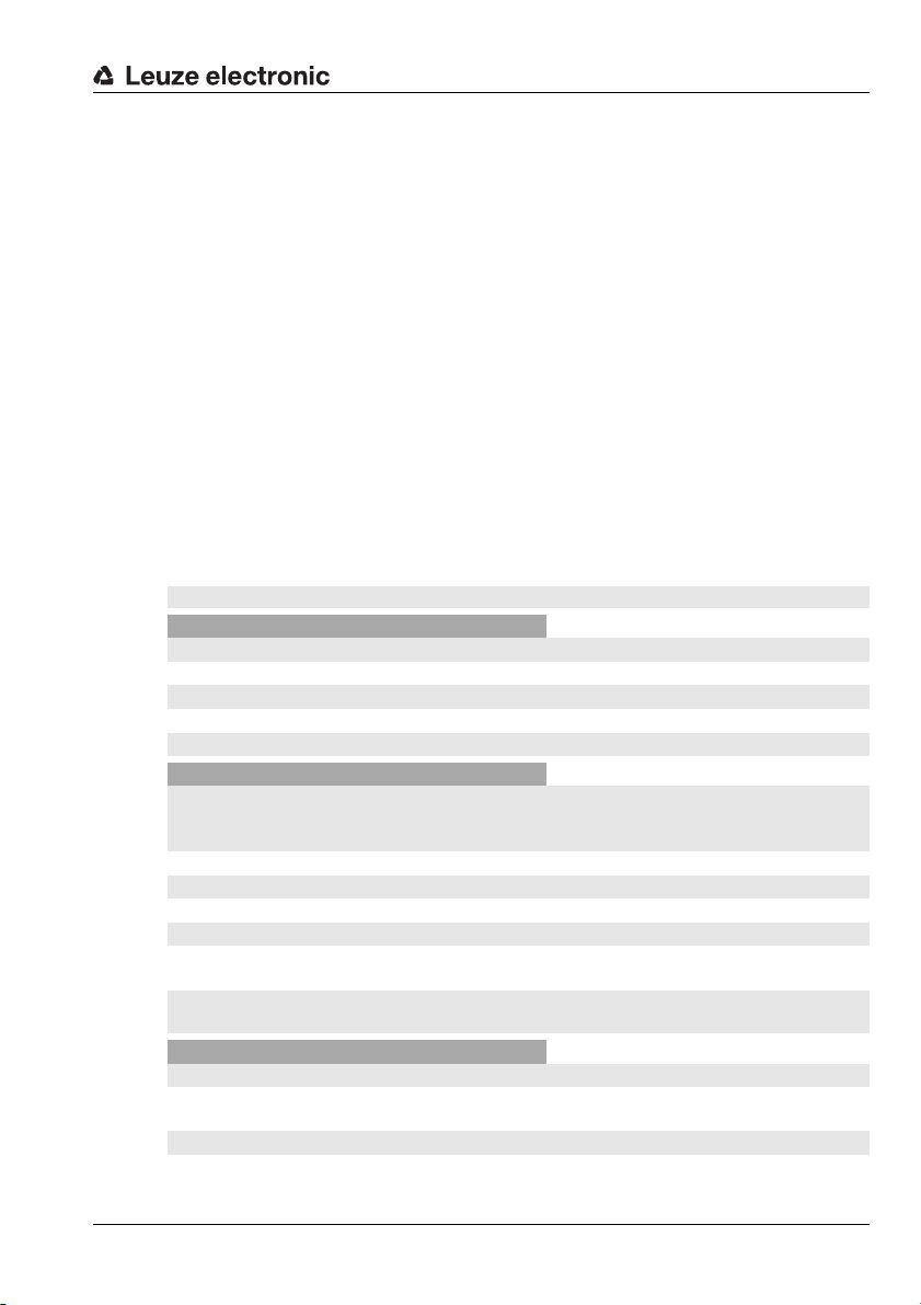
Figure 3.1: Application example: presence monitoring
Figure 3.1 shows the presence monitoring of printed lottery numbers with an LSIS 412i
during the printing of lottery tickets.
Figure 3.2: Application example: completeness monitoring
Figure 3.2 shows full-crate monitoring with an LSIS 412i.
Leuze electronic LSIS 4xxi 11
TNT 35/7-24V
Device description
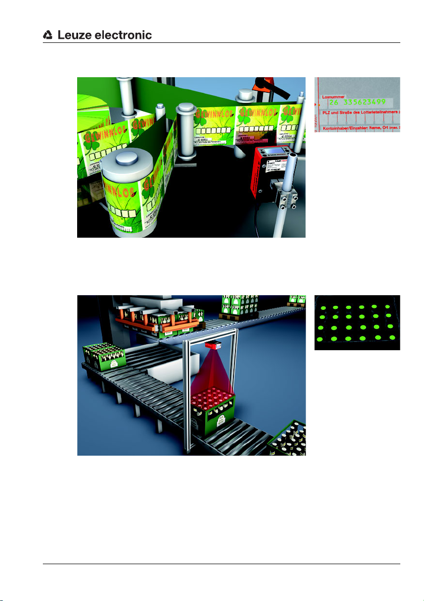
Figure 3.3: Application example: orientation detection
Figure 3.3 shows the detection of position and angle of individual parts with an LSIS 412i.
Application examples: code reading
Figure 3.4: Application example: code verification
Figure 3.4 shows the reading of a 1D code (Pharmacode) on pharmaceutical packages and
an optional verification of uniformity using a stored reference code with an LSIS 422i.
Leuze electronic LSIS 4xxi 12
TNT 35/7-24V
Device description
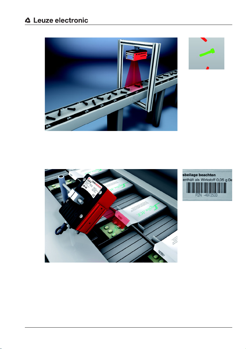
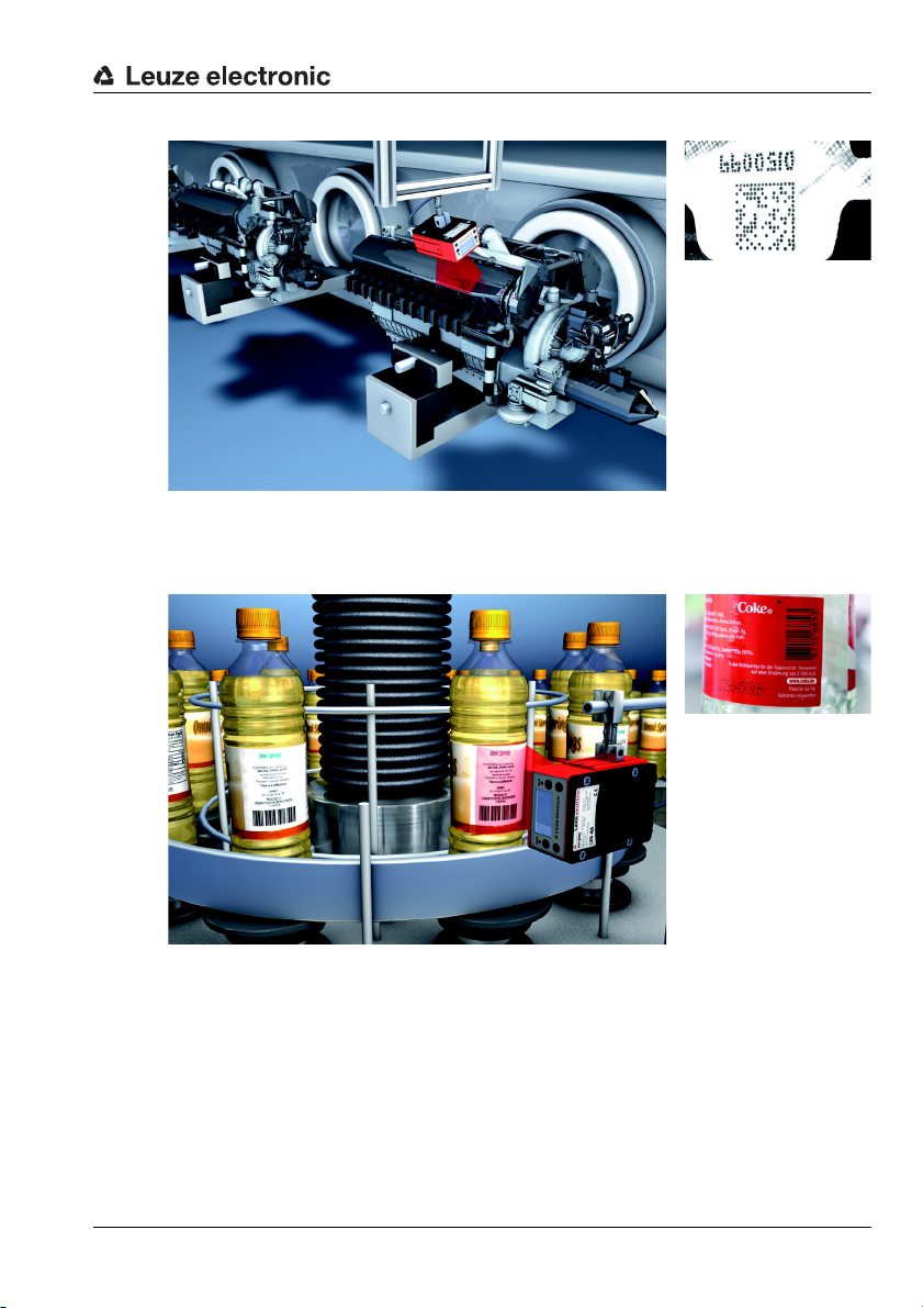
Figure 3.5: Application example: dot-peened Data Matrix code
Figure 3.5 shows the reading of dot-peened 2D codes on engine blocks with an LSIS 422i.
Figure 3.6: Application example: label positioning and label identification
Figure 3.6 shows the presence inspection for the correct label and the reading of the ’
1D code with an LSIS 462i.
Leuze electronic LSIS 4xxi 13
TNT 35/7-24V
Device description
Measuring tool application example
Figure 3.7: Application example - measurement of radii and roundness
Figure 3.7 shows the measurement of radii and roundness on a component by a LSIS 462i.
3.2 Characteristics of the smart cameras of the LSIS 4xxi series
Performance features:
• Diverse mounting options with dovetail technology or mounting threads on the front,
rear and narrow side of the device.
• Device models for C-mount interchangeable lenses.
• Motor-driven focus adjustment with automatic readjustment on change of check program.
• Integrated illumination with special optics for homogeneous illumination of the rectangular field of view, divided into 4 quadrants that can be switched on and off separately.
• Intuitive, backlit, multi-language display with user-friendly menu navigation.
• Real-time clock (time with date) with built-in backup battery.
• Adjustment of all device parameters with a web browser. No additional software
needs to be installed.
• M12 connections with Ultra-Lock™ technology.
• Eight freely programmable switching inputs/outputs for the activation or signaling of
states.
• Heavy-duty housing of protection class IP 65, IP 67.
TNT 35/7-24V
Notice!
Information on technical data and characteristics can be found in chapter 11.
Leuze electronic LSIS 4xxi 14

Device description
General information
Basic operation of the LSIS 4xxi is via a multi-language control panel (display with buttons).
The control panel can be used to view statistics and status messages. Two LEDs provide
additional optical information on the current operating state of the device.
The eight freely configurable switching inputs/outputs "SWIO 1 … SWIO 8" can be assigned
various functions and control e.g. activation of the LSIS 4xxi or communication with external
devices, such as a PLC.
The LSIS 4xxi can be operated and configured by means of the integrated webConfig via
the Ethernet service interface.
Figure 3.8: Detecting objects with webConfig
With webConfig, individual check programs can be set up for detecting objects. The object
being searched for is displayed in green in Figure 3.8.
Leuze electronic LSIS 4xxi 15
TNT 35/7-24V
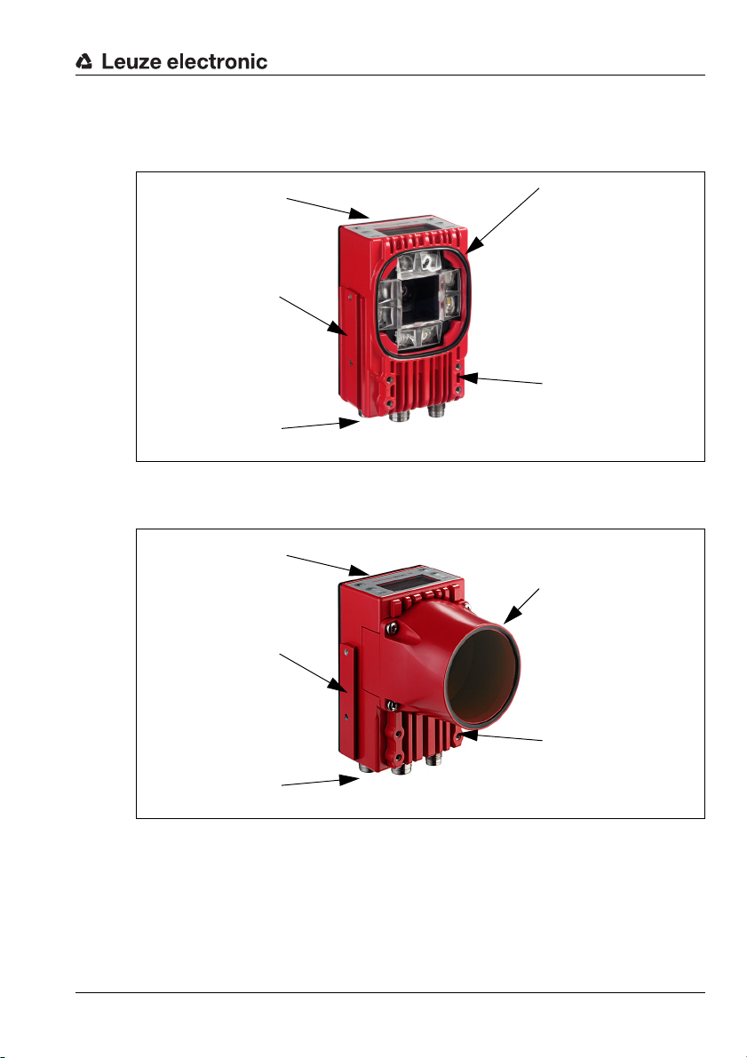
3.3 Device construction
Display, LEDs
and buttons
Integrated illumination
4 mounting threads on
both the front and rear as
well as dovetail mounting
on the rear
Dovetail mounting and
2 mounting threads on
the side
M12 connection
technology
Display, LEDs
and buttons
Removable, sealed lens
cover with front glass for
C-mount interchangeable
lenses
4 mounting threads on
both the front and rear as
well as dovetail mounting
on the rear
Dovetail mounting and
2 mounting threads on
the side
M12 connection
technology
Standard device
Figure 3.9: Standard device construction
Device models for C-mount interchangeable lenses
Device description
Leuze electronic LSIS 4xxi 16
Figure 3.10: Device construction variants for C-mount interchangeable lens
TNT 35/7-24V
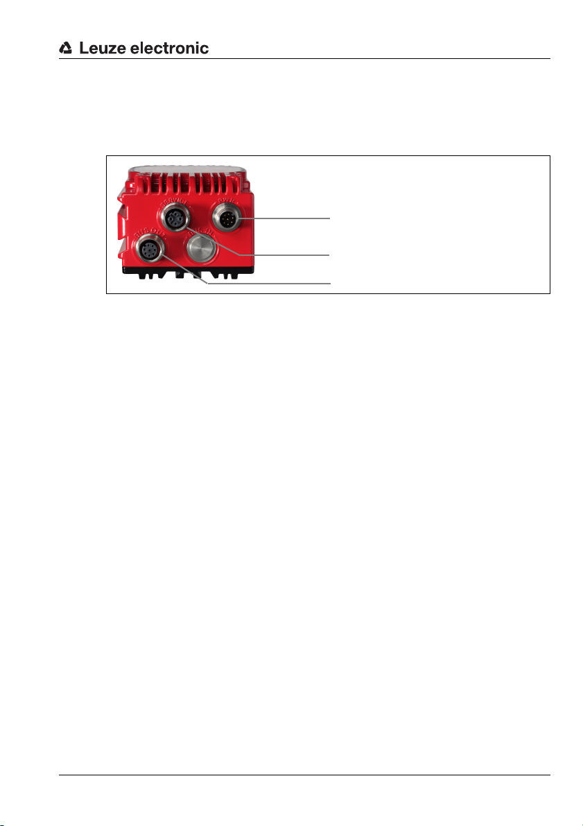
3.4 Stand-alone connection
Supply voltage + 4 I/O
Host and service interface (Ethernet)
4 I/O + RS232 (process interface)
The smart cameras of the LSIS 4xxi series can be operated as individual "stand alone"
devices. The LSIS 4xxi features multiple M12 connectors / sockets for the electrical connection of the supply voltage, the interfaces and the switching inputs and outputs.
Figure 3.11: Stand-alone connection
The host/service interface is used to configure the LSIS 4xxi. Configuration is performed via
the integrated webConfig, which can be accessed via a PC with a current browser.
The freely configurable switching inputs and outputs are used for process control.
The LSIS 4xxi can exchange data with the process control via the RS 232 or Ethernet
process interface. The protocol for the RS232 interface can be configured for the specific
application in webConfig.
No configurable framing protocol is available for the Ethernet process interface. A pure
ASCII protocol is used via Ethernet.
Device description
Leuze electronic LSIS 4xxi 17
TNT 35/7-24V
4 Installation and mounting
4.1 Storage, transportation
Attention!
When transporting or storing, package the device so that it is protected against collision and
humidity. Optimal protection is achieved when using the original packaging. Heed the
required environmental conditions specified in the technical data.
Unpacking
Check the packaging for any damage. If damage is found, notify the post office or
shipping agent as well as the supplier.
Check the delivery contents using your order and the delivery papers:
• Delivered quantity
• Device type and model as indicated on the nameplate
•Package insert
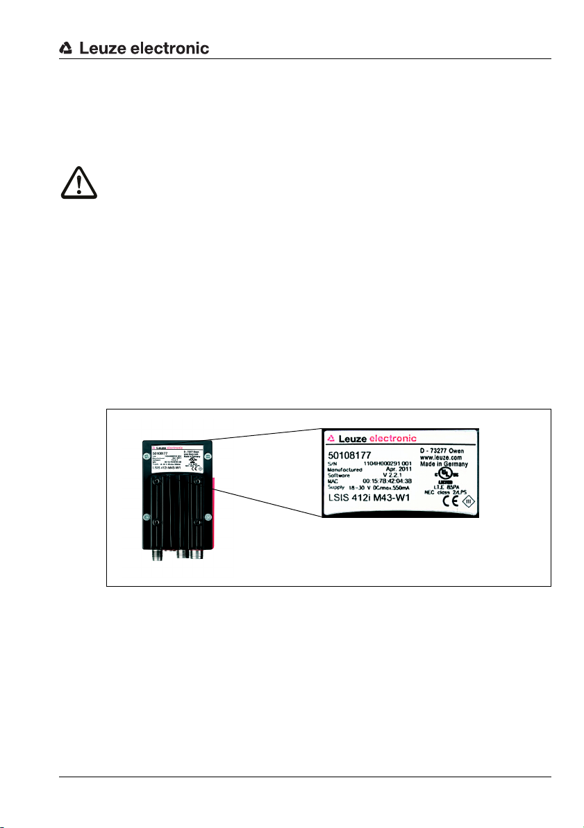
The name plate provides information as to what LSIS type your device is. For specific
information, please refer to chapter 9.
Name plates of the smart cameras of the LSIS 4xxi series
Installation and mounting
Figure 4.1: Device name plate LSIS 4xxi
Save the original packaging for later storage or shipping.
If you have any questions concerning your shipment, please contact your supplier or your
local Leuze electronic sales office.
Observe the applicable local regulations when disposing of the packaging materials.
Leuze electronic LSIS 4xxi 18
TNT 35/7-24V

4.2 Mounting the LSIS 4xxi
Thread depth 7mm Thread depth 4.5mmThread depth 4.5mm
The LSIS 4xxi smart cameras can be mounted in various ways:
• By means of four M4 screws on the rear of the device, four M4 screws on the front of
the device or two M4 screws on the narrow side of the device.
• By means of a BT 56/BT 59 mounting device on the two fastening grooves on the
narrow side or rear of the device.
4.2.1 Fastening with M4 x 6 screws
Figure 4.2: Fastening options using M4 threaded holes
Installation and mounting
Leuze electronic LSIS 4xxi 19
TNT 35/7-24V

4.2.2 Mounting devices
Clamping jaws for
mounting on the
LSIS 4xxi
Clamp profile for
mounting to round or
oval pipes
Ø16…20mm
A Rod holder, turnable 360°
B Rods Ø 16 … 20mm
All dimensions in mm
The BT 56 and BT 59 mounting devices are available for fastening the LSIS 4xxi. The BT 56
is designed for rod installation (Ø 16mm to 20 mm). The BT 59 is used to fasten to ITEM
aluminum profiles. For ordering instructions, please refer to chapter "Type overview and
accessories" on page 52.
BT 56 mounting device
Installation and mounting
Figure 4.3: BT 56 mounting device
Leuze electronic LSIS 4xxi 20
TNT 35/7-24V

Figure 4.4: Mounting examples of LSIS 4xxi with BT 56
Clamping jaws for mounting
on the LSIS 4xxi
A Holder, turnable 360°
B ITEM joint, angle adjustable ±90°
C M 8x16 screw cylinder, M 8 wave washer, M 8
sliding block, connectors for ITEM profile (2x)
All dimensions in mm
BT 59 mounting device
Installation and mounting
Figure 4.5: BT 59 mounting device
Leuze electronic LSIS 4xxi 21
TNT 35/7-24V

4.3 Device arrangement
4.3.1 Selecting a mounting location
In order to select the right mounting location, several factors must be considered:
• The camera distance which results from the respective field of view (see figure 4.6 on
page 23 or figure 4.7 on page 24).
• The permissible cable lengths between the LSIS 4xxi and the host system depending
on which interface is used.
• The display and control panel should be very visible and accessible.
• For configuring and commissioning with the webConfig tool, the service interface
should be easily accessible.
• Mount the LSIS 4xxi so that the object being inspected is not exposed to direct
sunlight or strong ambient light.
When selecting a mounting location, pay further attention to:
• Maintaining the required environmental conditions (temperature, humidity).
• Possible soiling of the viewing window due to liquids, abrasion by boxes, or
packaging-material residues.
• Lowest possible chance of damage to the LSIS 4xxi by mechanical collision or
jammed parts.
4.3.2 Determining the camera distance
In figure 4.6 and figure 4.7, the principle relationship between camera distance and the
resulting image field is represented for the C-mount device models.
In general, the visible image field increases with the camera distance. If a larger image field
is needed, the camera distance must be increased accordingly. This also results in a
decrease in the resolution of the image, however.
The diagram in figure 4.6 shows the relationship between camera distance (= path from the
front edge of the camera to the object) and image field for standard devices with 8mm and
16mm focal length. In figure 4.7, this relationship is represented for the C-mount device
models.
The following applies for devices with integrated illumination:
For camera distances between 50mm and 250mm, particularly homogeneous illumination
of the image field is ensured.
Larger camera distances can be realized than are represented in the respective diagrams.
In this case, the axis of the respective diagram is extrapolated.
Listed on the right side of the diagrams is the pixel size that corresponds to the respective
image field. A segmented object is detected in the image only if at least 16 pixels in size.
The following minimum module or cell sizes apply for code readings:
• Printed, high-contrast codes: 3 pixels
• Directly marked, low-contrast codes: 5 pixels
Installation and mounting
TNT 35/7-24V
Leuze electronic LSIS 4xxi 22

0 100 200 300 400 500 600 700 800 900 1000 1100
0
550 x 351
500 x 319
450 x 287
400 x 255
350 x 223
300 x 191
250 x 160
200 x 128
150 x 96
50 x 32
100 x 64
600 x 383
0.73
0.66
0.60
0.53
0.47
0.40
0.33
0.27
0.20
0.07
0
0.13
0.80
16 mm
8 mm
0
100
700
70x 45mm
400x 255mm
752 x 480px
752 x 480px
0
100
700
30 x 20mm
200 x 130mm
752 x 480px
752 x 480px
Field of view [mm]
Camera distance [mm]
Pixel size [mm]
Example:
Image field size at distances
of 100mm and 700 mm.
16mm lens
8mm lens
Installation and mounting
Leuze electronic LSIS 4xxi 23
Figure 4.6: Camera distance / image field - standard devices
TNT 35/7-24V

Installation and mounting
0 500 1000 1500 2000 2500
0
2000 x 1277
1800 x 1149
1600 x 1021
1400 x 894
1200 x 766
1000 x 638
800 x 510
600 x 383
200 x 128
400 x 255
2.39
2.13
1.86
1.6
1.33
1.06
0.80
0.27
0
0.53
2.66
6 mm
12 mm
16 mm
25 mm
35 mm
50 mm
75 mm
Field of view [mm]
Camera distance [mm]
Pixel size [mm]
Figure 4.7: Camera distance / image field - device models for C-mount interchangeable
lenses
Leuze electronic LSIS 4xxi 24
TNT 35/7-24V

Installation and mounting
4.4 Lens replacement LSIS 4xxi - C-mount devices
Attention!
Replace the lens in an environment that is as clean, dry and dust-free as possible. When
doing so, make sure the lens cover is properly mounted to ensure protection class IP 65 /
IP 67 is fulfilled.
First loosen the 4 Phillips screws on the lens cover and remove the cover to the front as
shown in figure 4.8.
Figure 4.8: Lens replacement for C-mount devices
Unscrew the installed C-mount lens from the lens mount in a clean environment by
turning it counter-clockwise and screw the new lens on by turning it clockwise on the lens
mount of the LSIS 4xxi M49-X9.
Leuze electronic LSIS 4xxi 25
TNT 35/7-24V

Installation and mounting
Screwable polarization filter
(part no. 50113242)
Notice!
Exchange and mounting of optical filters is described in the following chapter 4.5.
Replace the lens cover and re-tighten it with the 4 Phillips screws. Clean the window of
the lens cover of the LSIS 4xxi with a soft cloth after mounting.
4.5 Exchange / Mounting of optical filters
4.5.1 Mounting of optional polarization filter on standard device
An optional polarization filter (part no. 50113242, see chapter 9.3) can be mounted for the
standard device models of the LSIS 4xxi with integrated illumination.
Figure 4.9: Optional polarization filter for standard devices
The filter is mounted by screwing into the 4 front threaded blind holes.
Leuze electronic LSIS 4xxi 26
TNT 35/7-24V

4.5.2 Filter exchange for C-mount device
Daylight blocking filter
(part no. 50117985)
By default, an infrared filter is mounted between the camera chip and lens in the C-mount
device. If necessary, this can be replaced with a daylight blocking filter (part no. 50117985,
see chapter 9.3) for applications that work with infrared light.
Attention!
Only replace the filter in an environment that is very clean, dry and dust-free. It is best to
wipe off the replacement filter with a clean microfiber cloth before inserting the filter. Use
suitable gloves when doing this!
Installation and mounting
Figure 4.10: Filter replacement for C-mount devices
First, remove the lens cover and the lens as described in chapter 4.4.
Loosen the 3 retaining screws on the filter retaining ring (arrow in figure 4.10) and
carefully remove the retaining ring.
Carefully replace the filter plate.
No finger prints! Use lint-free gloves!
Re-mount the filter retaining ring and then the lens and lens covers as described in
chapter 4.4.
Notice!
Optionally, you can attach a conventional filter on the front filter thread of the C-mount
compact lens.
Leuze electronic LSIS 4xxi 27
TNT 35/7-24V

4.6 Cleaning
Clean the housing window of the LSIS 4xxi with a soft cloth after mounting. Remove all
packaging remains, e.g. carton fibers or Styrofoam balls. In doing so, avoid leaving
fingerprints on the front cover of the LSIS 4xxi.
Attention!
Do not use aggressive cleaning agents such as thinner or acetone for cleaning the device.
Use of improper cleaning agents can damage the housing window and display.
Notice for model with plastic screen:
The surfaces are preferably to be cleaned with standard household dishwashing soap mixed
in water, wiped with a soft cloth or sponge, and carefully dabbed dry (never rub intensely!).
For a thorough cleaning, solvent-free, antistatic plastic cleaners approved for use with plastics are recommended. Never use abrasive cleaners or organic solvents such as alcohol or
acetone, as these could scratch the surfaces or cause cracks to form.
Installation and mounting
Leuze electronic LSIS 4xxi 28
TNT 35/7-24V

5 Electrical connection
The smart cameras of the LSIS 4xxi series are connected using variously coded M12
connectors. This ensures unique connection assignments.
For the general locations of the individual device connections, please refer to the device
detail shown below.
Notice!
Ready-made cables are provided for all connections. For additional information, refer to
chapter 9.
Electrical connection
Figure 5.1: Location of the electrical connections
Leuze electronic LSIS 4xxi 29
TNT 35/7-24V

5.1 Safety notices for the electrical connection
Attention!
Do not open the device yourself under any circumstances! The housing of the LSIS 4xxi
contains no parts that need to be adjusted or maintained by the user.
Before connecting the device please ensure that the supply voltage matches the value
printed on the nameplate.
Connection of the device and cleaning must only be carried out by a qualified electrician.
Ensure that the functional earth (FE) is connected correctly. Unimpaired operation is only
guaranteed when the functional earth is connected properly.
If faults cannot be cleared, the device should be switched off from operation and protected
against accidental use.
Attention!
For UL applications, use is only permitted in class 2 circuits in accordance with the NEC
(National Electric Code).
The smart cameras of the LSIS 4xxi series are designed in accordance with safety class III
for supply by PELV (protective extra-low voltage) / SELV (safety extra-low voltage).
Notice!
Protection class IP 65 / IP 67 is achieved only if the connectors and caps are screwed into
place!
Electrical connection
Leuze electronic LSIS 4xxi 30
TNT 35/7-24V

5.2 Electrical connection of the LSIS 4x2i
PWR
IO1
IO6
IO7IO5
IO8
Rx
Tx
IO2
IO3
IO4
NC
VIN
GND
GND
FE
FE
BUS IN
TD+
1
2
3
4
RD+
RD-
TD-
SERVICE
BUS OUT
7
7
M12 socket
(D-coded)
M12 plug
(A-coded)
M12 socket
(A-coded)
The LSIS 4x2i is equipped with three M12 connectors/sockets which are A- and B-coded.
For subsequent interface variants, the space is reserved for a fourth connection.
• The voltage supply (18 … 30V DC) is connected at the PWR connector (Vin, GND).
• The 8 freely configurable switching inputs/outputs are connected to the PWR
connector and to the BUS OUT socket (IO1 … IO8).
• The RS 232 interface is a process interface of the LSIS 4xxi. It is connected to the
BUS OUT socket (Tx, Rx).
• The Ethernet cable for configuring and commissioning with webConfig and for
transferring process data is connected to the SERVICE connector.
Electrical connection
Figure 5.2: Connections of the LSIS 4x2i
Described in detail in the following are the individual connections and pin assignments.
Leuze electronic LSIS 4xxi 31
TNT 35/7-24V

Electrical connection
M12 plug
(A-coded)
5.2.1 PWR - voltage supply and switching inputs/outputs 1 to 4
PWR (8-pin connector, A-coded)
Pin Name Remark
PWR
IO1
GND
IO2
IO3
Table 5.1: Pin assignments - PWR
Preferably, use the "KD S-M12-8A-P1-…" ready-made cables, see table 9.6 "PWR
cables for the LSIS 4xxi" on page 54.
Supply voltage
Attention!
For UL applications, use is only permitted in class 2 circuits in accordance with the NEC
(National Electric Code).
The smart cameras of the LSIS 4xxi series are designed in accordance with safety class III
for supply by PELV (protective extra-low voltage) / SELV (safety extra-low voltage).
IO4
FE
VIN
7
NC
1 VIN Positive supply voltage +18 … +30VDC
2 IO1 Configurable switching input/output 1
3 GND Negative supply voltage 0V DC
4 IO2 Configurable switching input/output 2
5 IO3 Configurable switching input/output 3
6 IO4 Configurable switching input/output 4
7 NC Not Connected
8 FE Functional earth
Thread FE Functional earth (housing)
Connecting functional earth FE
Ensure that the functional earth (FE) is connected correctly. Unimpaired operation is only
guaranteed when the functional earth is connected properly. All electrical disturbances
(EMC couplings) are discharged via the functional earth connection.
Switching input / output
The smart cameras LSIS 4x2i feature 8 freely programmable, opto-decoupled switching
inputs / outputs IO1 … IO8.
The switching inputs can be used to activate various internal functions of the LSIS 4xxi
(triggering of image acquisition, check program selection …). The switching outputs are
used for the output of result and status messages and for triggering an external flash control.
Switching inputs/outputs IO1 to IO4 are located on the PWR M 12 connector.
Switching inputs/outputs IO5 to IO8 are located on the BUS OUT M 12-socket.
Leuze electronic LSIS 4xxi 32
TNT 35/7-24V

Electrical connection
18-30 V DC
O8
Switching input
Switching output
from controller
(deactivated)
Switching input
to controller
18-30 V DC
IO1 … IO8
Switching output
Switching output
from controller
Switching input
to controller
(deactivated)
Notice!
Assignment as input or output and the corresponding function can be set via webConfig!
If not explicitly configured in webConfig, the ports are preset as follows:
• IO1 start trigger input, triggers image acquisition
• IO2 result OK output, switches in event of positive evaluation result
• IO3 result NOK output, switches in event of negative evaluation result
• IO4 ready output, switches when ready for operation
Described in the following is the external wiring for use as a switching input or output; the
respective function assignments to the switching inputs/outputs are set in webConfig.
Function as switching input
IO1
I
Figure 5.3: Connection diagram of IO1 through IO8 configured as switching inputs
Function as switching output
Figure 5.4: Connection diagram of IO1 through IO8 configured as switching outputs
Attention!
Each configured switching output is short-circuit proof! Do not load the respective switching
output of the LSIS 4xxi with more than 60mA at +18 … +30VDC in normal operation!
Leuze electronic LSIS 4xxi 33
TNT 35/7-24V

Electrical connection
M12 socket
(A-coded)
IO6
IO7IO5
IO8
Rx
Tx
GND
FE
BUS OUT
7
Host
GND
Tx
Rx
up to 10m
Shield
5.2.2 BUS OUT - RS 232 and switching inputs/outputs 5 to 8
The RS 232 interface is used to output test results, see webConfig manual for details.
BUS OUT (8-pin socket, A-coded)
Pin Name Remark
BUS OUT
IO6
FE
7
Tx
Table 5.2: Pin assignment BUS OUT
Preferably, use the "KS S-M12-8A-P1-…" ready-made cables, see table 9.8 "BUS OUT
cables for the LSIS 4xxi" on page 55:
If using self-made cables, observe the following notice:
Notice for connecting the RS 232 interface!
Ensure adequate shielding. The entire connection cable must be shielded and earthed.
GND
IO7IO5
IO8
Rx
1 IO5 Configurable switching input/output 5
2 IO6 Configurable switching input/output 6
3 GND Negative supply voltage 0V DC
4 IO7 Configurable switching input/output 7
5 IO8 Configurable switching input/output 8
6 Rx Rx signal (RS 232)
7 Tx Tx signal (RS 232)
8 FE Functional earth
Thread FE Functional earth (housing)
RS 232 cable assignments
Figure 5.5: RS 232 pin assignments
Switching input / output
The freely configurable switching inputs/outputs are described in chapter 5.2.1.
Leuze electronic LSIS 4xxi 34
TNT 35/7-24V

5.2.3 SERVICE - Ethernet host/configuration interface
TD+
1
2
3
4
RD+
RD-
TD-
SERVICE
M12 socket
(D-coded)
TD+
RD+
TD
RD
SH
SERVICE RJ 45
TD+ (1)
TD- (2)
RD+ (3)
RD- (6)
1
8
Twisted pair
Twisted pair
The depicted core colors apply only for Leuze cables
and are not compliant with EIA/TIA 568A and EIA/TIA 568B.
The LSIS 4xxi makes an Ethernet interface available for configuration and for transferring
process data.
SERVICE (4-pin socket, D-coded)
Pin Name Remark
1 TD+ Transmit Data +
2 RD+ Receive Data +
3 TD- Transmit Data -
4 RD- Receive Data -
Thread FE Functional earth (housing)
Table 5.3: SERVICE pin assignments
Preferably, use the ready-made
and "KSS ET-M12-4A-RJ45-A-P7-…" cables, see "Accessories for the host/service interface" on page 56.
If using self-made cables, observe the following notice:
Notice for connecting the Ethernet interface!
Ensure adequate shielding. The entire connection cable must be shielded and earthed. The
RD+/RD- and TD+/TD- wires must be stranded in pairs.
Use at least CAT 5 cables for the connection.
"KS ET-M12-4A-P7-…", "KSS ET-M12-4A-M12-4A-P7-…"
Electrical connection
Ethernet cable assignment
Figure 5.6: Cable assignments - SERVICE on RJ-45
Leuze electronic LSIS 4xxi 35
TNT 35/7-24V

Commissioning and configuration
6 Commissioning and configuration
6.1 Establishing a connection between PC and LSIS 4xxi
6.1.1 Starting the device
Apply the supply voltage +18 … +30V DC (typ. +24VDC).
The camera starts up and the following message appears on the display:
Startup...
Leuze electronic
GmbH + Co. KG
After a few seconds, brief device information appears.
LSIS 412i M43 W1
Leuze electronic
GmbH + Co. KG
SW: V 0.51.0 HW:0
SN: 0902-082905016
Afterwards, the LSIS 4xxi switches to normal operation
RS232
and displays the active interfaces as a status message.
6.1.2 Establishing an Ethernet connection
The Ethernet connection is used as the host interface and for configuring the LSIS 4xxi via
a PC with a browser.
Notice!
In order for the PC and LSIS 4xxi to communicate with one another, both must be on the
same subnet and have different network addresses.
Normally, it is sufficient to adjust the Ethernet settings (= TCP/IP configuration) on one of the
two devices (LSIS 4xxi/PC) to those of the other device.
If the PC is normally connected to a network using DHCP address assignment, the easiest
way to access the LSIS 4xxi is to create an alternative configuration in the TCP/IP settings
of the PC. This method lends itself if the LSIS 4xxi is not connected to an existing network
during later operation. For further information on this topic, refer to chapter 6.1.3.
Alternatively, you can also integrate the LSIS 4xxi in an existing network and configure it
from a PC that is also connected to the network. For further information on this topic, refer
to chapter 6.1.4.
Leuze electronic LSIS 4xxi 36
TNT 35/7-24V

Commissioning and configuration
6.1.3 Configuring the LSIS 4xxi from a laptop without a network
Check the network address of the LSIS 4xxi by pressing the enter button three times
in sequence during normal operation of the LSIS 4xxi.
This switches you to the Network settings submenu, where you can read the current
settings of the LSIS 4xxi.
Note the values for Addr and Mask.
The value in Mask specifies which digits of the IP address of the PC and LSIS 4xxi must
match in order to communicate with one another.
Address of the LSIS 4xxi Net mask Address of the PC
192.168.060.101 255.255.255.0 192.168.060.xxx
192.168.060.101 255.255.0.0 192.168.xxx.xxx
Table 6.1: Address assignment in the Ethernet
Instead of xxx, you can now assign your PC any numbers between 000 and 255, but NOT
THE SAME numbers as used with the LSIS 4xxi.
E.g. 192.168.060.110 (but not 192.168.060.101!).
If the LSIS 4xxi and the PC have the same IP address, they cannot communicate with one
another.
Setting the IP address on the PC
Log into your PC as administrator.
Select Start->Control Panel to access the
Network Connections menu (Windows 2000/
XP) or Network and Sharing Center (Windows Vista/Windows 7).
There, select Local Area Connection and
right-click to open the corresponding properties
page.
Select Internet Protocol (TCP/IP) (scroll
down if necessary) and click Properties.
In the Internet Protocol (TCP/IP) Proper-
ties window, select the Alternate Configuration tab.
Set the IP address of the PC in the address
range of the LSIS 4xxi.
Attention: Not the same as for the LSIS!
Set the subnet mask of the PC to the same value as on the LSIS 4xxi.
Close the settings dialog by confirming all windows with OK.
Connect the "Service" interface of the LSIS 4xxi directly to the LAN port of your PC.
TNT 35/7-24V
Leuze electronic LSIS 4xxi 37

Commissioning and configuration
Figure 6.1: Connecting the LSIS 4xxi to the PC
The PC first tries to establish a network connection via the automatic configuration. This
takes a few seconds, after which the alternate configuration, which you just set, is activated.
The PC can then communicate with the LSIS 4xxi.
6.1.4 Integrating the LSIS 4xxi in an existing network
If it should be possible to reconfigure the LSIS 4xxi later during running operation and if a
network connection is present at the installation site, you can set the LSIS 4xxi according to
the parameters of the existing network. In principle, it is possible in this case to have the
address set automatically by means of DHCP, or you can assign a fixed address.
Ask your network administrator which method is to be used and — if using fixed address
assignment — which settings should be used for address, subnet mask and gateway.
With DHCP server
Use the display on the LSIS to activate the DHCP function (see "Changing the network
settings on the display" on page 49).
Following activation of the DHCP function, the sensor automatically restarts. If you now
connect the sensor to a network with DHCP server, it is automatically assigned an IP
address.
You can now configure the LSIS 4xxi via any PC on the same network.
With fixed IP address
Use the display on the LSIS to set the parameters previously received by the network
administrator (see "Changing the network settings on the display" on page 49).
The sensor restarts after the Ethernet configuration is changed. If you now connect the
sensor to a network, it operates with the manually assigned IP address.
You can now configure the LSIS 4xxi via any PC on the same network.
TNT 35/7-24V
Leuze electronic LSIS 4xxi 38

6.2 Configuring via webConfig
With Leuze webConfig, an operating-system independent, web-technology based, graphical user interface is available for configuring smart cameras of the LSIS 4xxi series.
Through the use of HTTP as communication protocol and by using only standard technologies on the client side (HTML, JavaScript and AJAX), which are supported by all commonly
used, modern browsers (e.g. Mozilla Firefox beginning with Version 3.0 or Internet
Explorer beginning with Version 8.0), it is possible to operate the Leuze webConfig tool
on any internet-ready PC.
Start a browser on your PC and enter the following address: 192.168.60.101 or the address
previously set by you / the address assigned by the DHCP server.
192.168.60.101 is the default Leuze service address for communication with the
smart cameras of the LSIS 4xxi series.
You can check the network address of the LSIS 4xxi by pressing the enter button on the
display three times in sequence during normal operation of the LSIS 4xxi.
If the IP address is entered correctly in the browser, the following start page appears on your
PC.
Commissioning and configuration
Figure 6.2: webConfig start page
Notice!
The webConfig tool is completely contained in the firmware of the LSIS 4xxi. Depending on
firmware version, the start page may vary from that shown above.
Leuze electronic LSIS 4xxi 39
TNT 35/7-24V

Commissioning and configuration
The webConfig menus are intuitive to operate and contain both help texts as well as tooltips.
Because the webConfig user interface is always being developed further, it is described in
a separate software description. All released versions of this software description can be
found in the download area of the Leuze electronic homepage: www.leuze.com/...
Activities in webConfig
Use webConfig to set up the LSIS 4xxi. When doing so, observe the following points:
• Configure at least one check program and activate it.
• Set up one of the 8 IOs as a trigger input for the check program. Make certain that this
input is correctly connected (see chapter 5.2).
• If you use the RS 232 interface to communicate with the process control, you must
configure the transmission parameters of the RS 232 interface in the data output tool
of the respective check program.
For information on how that functions in webConfig, please refer to the webConfig software
description.
Leuze electronic LSIS 4xxi 40
TNT 35/7-24V

7 Display and control panel
IO1 IO2 IO3 IO4
IO5 IO6 IO7 IO8
ATT ERR TMP
RS232
ETH 100
OK
LED
LED
Control buttons
Configurable result output
Status display
Interfaces
7.1 Structure of the control panel
Figure 7.1: Structure of the control panel
Display and control panel
7.2 Status display and operation
7.2.1 Indicators in the display
IO1 … IO8 Switching input or output 1 … 8 active (function depends on set
configuration).
ATT Warning (Attention)
ERR Internal device error (Error)
TMP Permissible internal device temperature exceeded / not met
Leuze electronic LSIS 4xxi 41
RS232 Type of integrated process interface
ETH Status display for the Ethernet connection:
In the center of the display, optional check program-specific displays can be displayed.
• ETH100 means that a 100Mbit Ethernet connection exists.
• ETH10 means that a 10Mbit Ethernet connection exists.
• If ETH is not displayed, there is no Ethernet connection.
TNT 35/7-24V

7.2.2 Control buttons
ESC
Up Navigate upward/laterally.
Down Navigate downward/laterally.
ESC
ESC Exit menu item.
ENTER Confirm/enter value, change menu levels.
Navigating within the menus
The menus within a level are selected with the up/down buttons .
The selected menu item is activated with the enter button .
Press the ESC button to move up one menu level.
When one of the buttons is actuated, the display illumination is activated for 10 min.
Setting values
If input of a value is possible, the display looks like this:
0000|
<-|0123456789 save
Standard ----- Unit
0000 | |
Display and control panel
Use the and buttons to set the desired value. An accidental, incorrect entry can be
corrected by selecting
<-| and then pressing .
Then use the buttons to select save and save the set value by pressing .
Selecting options
If options can be selected, the display looks like this:
o OFF
ON
Standard ----- Unit
OFF | |
TNT 35/7-24V
Select the desired option with the buttons. Activate the option by pressing .
Leuze electronic LSIS 4xxi 42

7.2.3 LED status displays
PWR LED
off Device OFF
flashes green Device ok, initialization phase
green continuous light Device ok
orange continuous light Service mode
flashes red Device ok, warning set
Display and control panel
- no supply voltage
- no inspection possible
- voltage connected
- self test running
- initialization running
- check program is activated
- inspection mode
- self test successfully finished
- device monitoring active
- configuration mode
- configuration via webConfig
- inspection mode
- temporary operating fault
- for details, see "Error signaling via LED" on page 51
red continuous light Device error / parameter enable
- no inspection possible
- for details, see "Error signaling via LED" on page 51
BUS LED
off No supply voltage
- no communication possible
flashes green Bus initialization
- can be very short, 1 pulse
green continuous light BUS ok
- device ready for sending/receiving
flashes red Communication error
- UART error (frame error, parity error, …)
Leuze electronic LSIS 4xxi 43
TNT 35/7-24V

7.3 Menu description
After voltage is applied to the smart camera, a startup screen is displayed for several
seconds. Afterwards, the main menu appears in the display.
7.3.1 The main menus
Display and control panel
LSIS 400i
Leuze electronic
GmbH + Co. KG
SW: V 2.2.1 HW: V 01.09
SN: 0508A123456 001
IO1 IO2 IO3 IO4 RS232
IO5 IO6 IO7 IO8 ETH 100
ATT ERR TMP
OK
Stat isti cs
Counter state
Tested: 0
OK: 0
NOK: 0
Parameter
Parameter handling
Display settings
Program selection
Ethernet
Language
o Deutsch
o English
o Español
o Français
o Italiano
Device information - main menu
Information about
• Device type
• Software version
• Hardware version
• Serial number
Status displays - main menu
• Status displays of the switching inputs/outputs
• Display of warnings and errors
• Status information for the device interfaces
• Optional: check program-specific display
See "Status displays" on page 45.
Statistics - main menu
Statistics data for the smart camera.
See "Statistics" on page 45.
Parameter - main menu
Configuration of the smart camera.
See "Parameter menu" on page 46.
Language selection - main menu
Selection of the display language.
See "Language selection menu" on page 47.
TNT 35/7-24V
Ser vi ce
Status messages
Service - main menu
Camera diagnosis and status messages.
See "Service menu" on page 47.
Leuze electronic LSIS 4xxi 44

Notice!
The display offers only limited configuration options. The configurable parameters are
described here in chapter 7.3.
Only the webConfig provides complete configuration options and is largely self-explanatory.
The use of the webConfig tool is described in chapter 6. There, you will also find notes on
commissioning with the aid of webConfig.
7.3.2 Status displays
Display and control panel
IO1 IO2 IO3 IO4 RS232
IO5 IO6 IO7 IO8 ETH 100
ATT ERR TMP
Status
Network settings
Sw. inputs/outputs
Network settings
Channel 1:
Addr: 192.168.60.101
Mask: 255.255.255.0
Gateway: 0.0.0.0
ESC
# Name Status
1 Start trigger I
2 Result OK O
3 Result NOK O
4 Programmable 1 O
5 Programmable 2 O
7.3.3 Statistics
Stat isti cs
Counter state
Tested: 0
OK: 0
NOK: 0
OK
Status displays - main menu
• Status displays of the switching inputs/outputs
• Display of warnings and errors
• Status information for the device interfaces
• Optional: check program-specific display
See "Indicators in the display" on page 41.
Press the enter button to select between network settings and switching
inputs and outputs.
The Network settings submenu offers information on the set network
address of the LSIS 4xxi, the corresponding net mask and the gateway
address.
Value "Channel 1" is displayed by default. Currently (06/2009), only one
Ethernet channel is supported.
The Sw. inputs / outputs submenu offers information on the current
configuration of the IOs of the LSIS 4xxi.
For each of the 8 IOs, the assigned name and state are displayed
(input = I/output = O).
TNT 35/7-24V
Statistics - main menu
In the Statistics menu, you can see the total number of parts that have
been checked since the last time the counter was reset, how many test
results were OK and how many were not OK.
Leuze electronic LSIS 4xxi 45

7.3.4 Parameter menu
Display and control panel
Parameter
Parameter handling
Display settings
Program selection
Ethernet
Parameter - main menu
Editing Ethernet addressing and selecting check programs stored on the
LSIS 4xxi.
Parameter handling
The Parameter handling submenu is used to lock and release the parameter input via the
display and for resetting to default values.
Level 3 Level 4 Selection/configuration option
Parameter enable OFF/ON
Default parameters By pressing the enter button after selecting
Description
OFF
The standard setting (
parameter changes.
If parameter enabling is activated (
changed manually.
Parameters to default
their standard settings without any further security
prompts.
In this case, English is selected as the display language.
) prevents unintended
ON
), parameters can be
, all parameters are reset to
Standard
OFF
Table 7.1: Parameter handling submenu
Display settings
In the Display settings submenu, the complete display can be turned upside down,
meaning turned by 180°, via the Turn by 180˚ menu item to enable good display readability
at the mounting site, if necessary.
Program selection
In the Program selection submenu, a scrollbar can be used to activate any of the check
programs stored on the LSIS 4xxi.
A selected program is immediately activated by pressing the enter button. If, however, a test
cycle is currently being executed at this moment, this test cycle is executed to completion
and evaluated.
As the new check program is being activated, the green "PWR" LED flashes.
TNT 35/7-24V
Level 3 Level 4 Selection/configuration option
Program name 1 Here, you will find check programs previously set in
Program name 2
Program name 3
…
Description
webConfig.
Standard
Table 7.2: Program selection submenu
Leuze electronic LSIS 4xxi 46

Display and control panel
Ethernet
The host/service interface of the LSIS 4xxi is configured in the Ethernet submenu.
Level 3 Level 4 Selection/configuration option
Ethernet 1 IP address The IP address can be set to any value in the
Gateway
Net mask
DHCP
activated
Description
xxx.xxx.xxx.xxx format.
Normally, the network administrator specifies the IP
address that is to be set here. If DHCP is activated, the
setting made here has no effect and the LSIS 4xxi is set to
the values that it obtains from the DHCP server.
The gateway address can be set to any value in the
xxx.xxx.xxx.xxx format.
The LSIS 4xxi communicates with participants in other
subnets via the gateway. Splitting the read application
over multiple subnets is rather uncommon; the setting of
the gateway address, thus, usually has no meaning.
The net mask can be set to any value in the
xxx.xxx.xxx.xxx format.
Usually, the LSIS 4xxi is used in a private Class C network
and the default setting can be accepted without change.
Attention: It is possible to enter any values for
xxx.xxx.xxx.xxx. Only the values 255 or 000 are
permissible for xxx, however. If other values are set, an
error message appears upon restart of the LSIS 4xxi.
Off/On
If DHCP is activated, the LSIS 4xxi draws its settings for
IP address, gateway and net mask from a DHCP server.
The manual settings made above have no effect, but are
retained and are again active if DHCP is deactivated.
Table 7.3: Ethernet submenu
7.3.5 Language selection menu
5 display languages are available:
• Deutsch (German)
• English
• Español (Spanish)
• Français (French)
• Italiano (Italian)
Standard
192.168.060.101
000.000.000.000
255.255.255.000
Off
TNT 35/7-24V
7.3.6 Service menu
Status messages
This menu item is used exclusively for service purposes by Leuze electronic.
Leuze electronic LSIS 4xxi 47

7.4 Operation
ESC
ESC
Shown here is an example describing important operating procedures in detail.
Parameter enabling
During normal operation parameters can only be viewed. If parameters need to be changed,
the ON menu item in the Parameter enabling menu must be activated. To do this proceed
as follows:
Parameter
Parameter handling
Display settings
Program selection
Ethernet
Parameter handling
o Parameter enable
Parameters to default
Parameter enable
OFF
oON
Standard ----- Unit
OFF | |
Parameter enable
OFF
OON
Standard ----- Unit
OFF | |
Display and control panel
In the Parameter menu, use the buttons to select the
Parameter handling menu item.
Press the enter button to enter the Parameter handling
menu.
In the Parameter handling menu, use the buttons to
select the Parameter enable menu item.
Press the enter button to enter the Parameter enable
menu.
In the Parameter enable menu, use the buttons to
select the ON menu item.
Press the enter button to switch on parameter enabling.
The PWR LED lights up orange. You can now set
individual parameters via the display.
TNT 35/7-24V
Press the ESC button twice to return to the main menu.
Leuze electronic LSIS 4xxi 48

Display and control panel
ESC
Network configuration
Information on network configuration can be found in chapter "Commissioning and configuration" on page 36. If you need to set the IP address of the LSIS 4xxi via the display, proceed
as follows:
Changing the network settings on the display
Parameter
Parameter handling
Display settings
Program selection
Ethernet
Ethernet
o Ethernet 1
Ethernet 1
IP address
Gateway
Net mask
DHCP activated
Configuration changed:
System must be
restarted
ok
cancel
In the Parameter menu, use the buttons to select the
Ethernet menu item.
Press the enter button to enter the Ethernet menu.
Press the enter button again to enter the Ethernet 1
menu.
Use the buttons successively to select the
IP address, Gateway and Net mask menu items and
set the desired values or activate the DHCP function.
Exit the Ethernet 1 menu with the ESCAPE button.
The message shown at the side appears. Confirm with OK
to initiate a restart and to activate the changed
configuration.
TNT 35/7-24V
Leuze electronic LSIS 4xxi 49

Display and control panel
Check program selection
During running operation of the LSIS 4xxi, you can simply change the check program via the
display. Prerequisite for this is that multiple check programs were set up previously via
webConfig.
Parameter
Parameter handling
Display settings
Program selection
Ethernet
Program selection
oBlob
Program 2
Program 3
…
ESC ESC
In the Parameter menu, use the buttons to select the
Program selection menu item.
Press the enter button to enter the Parameter handling
menu.
In the Program selection menu, use the buttons to
select the desired check program.
Press the enter button to activate the check program.
A selected program is immediately activated by pressing
the enter button. If, however, a test cycle is currently being
executed at this moment, this test cycle is executed to
completion and evaluated.
As the new check program is being activated, the green
"PWR" LED flashes.
Press the ESC button twice to return to the main menu.
Leuze electronic LSIS 4xxi 50
TNT 35/7-24V

8 Diagnostics and troubleshooting
8.1 Error signaling via LED
Error Possible error causes Measures
Status LED PWR
Off
Red, flashing
Red, continuous light • Error: function may be impossible
Orange, continuous light
Status LED BUS
Off
Red, flashing • Communication error
Table 8.1: General causes of errors
Notice!
Please use chapter 8 as a master copy should servicing be required.
Cross the items in the "Measures" column which you have already examined, fill out the
following address field and fax the pages together with your service contract to the fax
number listed below.
• No supply voltage connected to the
device
• Hardware error
• Warning
• Device in service mode
(parameter enable)
• No supply voltage connected to the
device
• Hardware error
Diagnostics and troubleshooting
❏ Check supply voltage
❏ Send device to customer service
❏ Query diagnostic data and carry out the
resulting measures
❏ Internal device error
❏ Reset service mode with webConfig or
display
❏ Check supply voltage
❏ Send device to customer service
❏ Check interface
Customer data (please complete)
Device type:
Software version :
Company:
Customer order number:
Contact person/ Department:
Phone (direct):
Fax:
Street / No:
ZIP code/City:
Country:
Leuze Service fax number:
+49 7021 573 - 199
Leuze electronic LSIS 4xxi 51
TNT 35/7-24V

Type overview and accessories
9 Type overview and accessories
9.1 Type overview LSIS 4xxi - standard devices
Type designation Focal
LSIS 412i M43-W1 8 mm Glass White
LSIS 412i M43-W1-01 8mm Plastic White
LSIS 412i M43-I1 8 mm Glass Infrared
LSIS 412i M43-I1-01 8 mm Plastic Infrared
LSIS 412i M43-M1 8mm Glass RGBW
LSIS 412i M43-M1-01 8mm Plastic RGBW
LSIS 412i M45-W1 16 mm Glass White
LSIS 412i M45-W1-01 16mm Plastic White
LSIS 412i M45-I1 16 mm Glass Infrared
LSIS 412i M45-I1-01 16 mm Plastic Infrared
LSIS 412i M45-M1 16mm Glass RGBW
LSIS 412i M45-M1-01 16mm Plastic RGBW
LSIS 422i M43-W1 8 mm Glass White
LSIS 422i M43-W1-01 8mm Plastic White
LSIS 422i M43-I1 8 mm Glass Infrared
LSIS 422i M43-I1-01 8 mm Plastic Infrared
LSIS 422i M43-M1 8mm Glass RGBW
LSIS 422i M43-M1-01 8mm Plastic RGBW
LSIS 422i M45-W1 16 mm Glass White
LSIS 422i M45-W1-01 16mm Plastic White
LSIS 422i M45-I1 16 mm Glass Infrared
LSIS 422i M45-I1-01 16 mm Plastic Infrared
LSIS 422i M45-M1 16mm Glass RGBW
LSIS 422i M45-M1-01 16mm Plastic RGBW
LSIS 462i M43-W1 8 mm Glass White
LSIS 462i M43-W1-01 8mm Plastic White
LSIS 462i M43-I1 8 mm Glass Infrared
LSIS 462i M43-I1-01 8 mm Plastic Infrared
LSIS 462i M43-M1 8mm Glass RGBW
LSIS 462i M43-M1-01 8mm Plastic RGBW
LSIS 462i M45-W1 16 mm Glass White
LSIS 462i M45-W1-01 16mm Plastic White
LSIS 462i M45-I1 16 mm Glass Infrared
LSIS 462i M45-I1-01 16 mm Plastic Infrared
LSIS 462i M45-M1 16mm Glass RGBW
LSIS 462i M45-M1-01 16mm Plastic RGBW
length of
lens
Housing window Color of LED
illumination
Table 9.1: Type overview LSIS 4xxi - standard devices
Function range Part no.
Blob
analysis
Code
reading
Measuring
tool
50108177
50112928
50116970
50116969
50116972
50116971
50108990
50112929
50116974
50116973
50116976
50116975
50108178
50113055
50116978
50116977
50116980
50116979
50109829
50113054
50116982
50116981
50116984
50116983
50113053
50113052
50116986
50116985
50116988
50116987
50113051
50113037
50116990
50116989
50116992
50116991
TNT 35/7-24V
Leuze electronic LSIS 4xxi 52

Type overview and accessories
9.2 Type overview LSIS 4xxi - C-mount devices and lenses
C-mount device models
Type designation Focal
LSIS 412i M49-X9 see lens Glass –
LSIS 412i M49-X9-01 see lens Plastic –
LSIS 422i M49-X9 see lens Glass –
LSIS 462i M49-X9 see lens Glass –
length of
lens
Housing window Color of LED
illumination
Function range Part no.
Blob
analysis
Code
reading
Measuring
tool
50117094
50121148
50117093
50117091
Table 9.2: Type overview LSIS 4xxi - C-mount devices
C-mount lenses
Type designation Description Focal length Diaphragm Part no.
V-LENS-K-C-6-F1,4-1/2-01
V-LENS-K-C-12-F1,4-1/2-01
V-LENS-K-C-16-F1,4-2/3-01
V-LENS-K-C-25-F1,4-2/3-01
V-LENS-K-C-35-F1,6-2/3-01
V-LENS-K-C-50-F2,8-2/3-01
V-LENS-K-C-75-F2,8-2/3-01
High-resolution C-mount
compact lens CP 6-M
High-resolution C-mount
compact lens CP 12-M
High-resolution C-mount
compact lens CP 16-M
High-resolution C-mount
compact lens CP 25-M
High-resolution C-mount
compact lens CP 35-M
High-resolution C-mount
compact lens CP 50-M
High-resolution C-mount
compact lens CP 75-M
6mm 1.4 50117050
12mm 1.4 50037055
16mm 1.4 50117051
25mm 1.4 50117052
35mm 1.6 50104978
50mm 2.8 50036468
75mm 2.8 50117053
Table 9.3: Type overview LSIS 4xxi - C-mount lenses
9.3 Accessories
Type designation Description Part no.
BT 56 Mounting device with dovetail for rod 50027375
BT 59 Mounting device with dovetail for ITEM aluminum profile 50111224
LSIS-ZUB-FIL-01 Screwable polarization filter for standard devices with integrated illumination 50113242
LSIS-ZUB-FIL-02 Daylight blocking filter for C-mount devices 50117985
REF 7A-100x100 Adhesive reflective tape, 100mm x 100 mm 50111527
REF 7A-200x300 Adhesive reflective tape, 200mm x 300 mm 50116687
REF 7A-1000x600 Adhesive reflective tape, 1000mm x 600mm 50115444
Table 9.4: Accessories for the LSIS 4xxi
Leuze electronic LSIS 4xxi 53
TNT 35/7-24V

Type overview and accessories
PWR
IO1
IO2
IO3
IO4
NC
VIN
GND
FE
7
M12 socket
(A-coded)
Notice!
External illuminations can be found in the current "Identification systems/Data transmission
systems/Distance measurement" catalog under "Industrial image processing" –> "Image
processing- general accessories"
9.4 Accessory ready-made cables for voltage supply
9.4.1 Contact assignment of PWR connection cable
PWR connection cable (8-pin socket, A-coded)
Pin Name Core color
1VIN White
2IO1 Brown
3 GND Green
4IO2 Yellow
5 IO3 Gray
6IO4 Pink
7NC Blue
8FE Red
Thread FE Bright
Table 9.5: Pin assignments KD S-M12-8A-P1-…
9.4.2 Order codes of the cables for voltage supply
Type designation Description Part no.
M12 socket for PWR, axial connector, open cable end, shielded
KD S-M12-8A-P1-020 Cable length 2 m 50135127
KD S-M12-8A-P1-050 Cable length 5 m 50135128
KD S-M12-8A-P1-100 Cable length 10 m 50135129
KD S-M12-8A-P1-150 Cable length 15 m 50135130
KD S-M12-8A-P1-250 Cable length 25 m 50135131
KD S-M12-8A-P1-500 Cable length 50 m 50135132
Table 9.6: PWR cables for the LSIS 4xxi
Leuze electronic LSIS 4xxi 54
TNT 35/7-24V

Type overview and accessories
IO6
IO7
IO5
IO8
Rx
Tx
GND
FE
BUS OUT
7
M12 plug
(A-coded)
9.5 Accessory ready-made cables for bus connection
9.5.1 Contact assignment BUS OUT connection cable
BUS OUT (8-pin. connector, A-coded)
Pin Name Core color
1IO5 White
2IO6 Brown
3 GND Green
4IO7 Yellow
5 IO8 Gray
6Rx Pink
7Tx Blue
8FE Red
Thread FE Bright
Table 9.7: Pin assignments KS S-M12-8A-P1-…
9.5.2 Order codes BUS OUT connection cables
Type designation Description Part no.
M12 plug for BUS OUT, axial connector, open cable end, shielded
KS S-M12-8A-P1-020 Cable length 2 m 50135138
KS S-M12-8A-P1-050 Cable length 5 m 50135139
KS S-M12-8A-P1-100 Cable length 10 m 50135140
KS S-M12-8A-P1-150 Cable length 15 m 50135141
KS S-M12-8A-P1-300 Cable length 30 m 50135142
Table 9.8: BUS OUT cables for the LSIS 4xxi
Notice!
Operation of the RS 232 host interface is only permissible with shielded cables with
maximum cable length of 10m.
Leuze electronic LSIS 4xxi 55
TNT 35/7-24V

Type overview and accessories
M12 plug
(D-coded)
9.6 Accessories for the host/service interface
9.6.1 Ready-made cables with M12 plug/open cable end
M12 Ethernet connection cable (4-pin plug, D-coded, open cable end)
Service
RD+
TD
SH
Type designation Description Part no.
M12 plug for SERVICE, axial connector, open cable end
KS ET-M12-4A-P7-020 Cable length 2m 50135073
KS ET-M12-4A-P7-050 Cable length 5m 50135074
KS ET-M12-4A-P7-100 Cable length 10m 50135075
KS ET-M12-4A-P7-150 Cable length 15m 50135076
KS ET-M12-4A-P7-300 Cable length 30m 50135077
Table 9.9: Ethernet connection cables featuring M12 plug/open cable end
TD+
RD
Name Pin
(M12)
TD+ 1 Yellow
RD+ 2 White
TD- 3 Orange
RD- 4 Blue
FE SH (thread) -
Core color
Leuze electronic LSIS 4xxi 56
TNT 35/7-24V

Type overview and accessories
M12 plug
(D-coded)
9.6.2 Ready-made cables with M12 plug/RJ-45 plug
M12 Ethernet connection cable (4-pin plug, D-coded, M 12 to RJ-45)
Service
RD+
TD
SH
Type designation Description Part no.
M12 plug for SERVICE to RJ-45 plug
KSS ET-M12-4A-RJ45-A-P7-020 Cable length 2 m 50109880
KSS ET-M12-4A-RJ45-A-P7-050 Cable length 5 m 50109881
KSS ET-M12-4A-RJ45-A-P7-100 Cable length 10 m 50109882
KSS ET-M12-4A-RJ45-A-P7-150 Cable length 30 m 50109886
KSS ET-M12-4A-RJ45-A-P7-300 Cable length 30 m 50109886
Table 9.10: Ethernet connection cables M 12 connector/RJ-45
TD+
RD
Name Pin
(M12)
TD+ 1 Yellow 1
RD+ 2 White 3
TD- 3 Orange 2
RD- 4 Blue 6
FE SH (thread) -
Core color Pin
(RJ-45)
Leuze electronic LSIS 4xxi 57
TNT 35/7-24V

Type overview and accessories
M12 plug
(D-coded)
9.6.3 Ready-made cables with M12 plug/M 12 plug
M12 Ethernet connection cable (4-pin connector, D-coded, on both sides)
Service
TD
SH
Type designation Description Part no.
M12 connector + M12 connector for SERVICE
KSS ET-M12-4A-M12-4A-P7-020 Cable length 2m 50106899
KSS ET-M12-4A-M12-4A-P7-050 Cable length 5m 50106900
KSS ET-M12-4A-M12-4A-P7-100 Cable length 10m 50106901
KSS ET-M12-4A-M12-4A-P7-150 Cable length 30m 50106905
Table 9.11: Ethernet connection cables featuring M 12 plug/M 12 plug
9.6.4 Connector
RD+
TD+
RD
Name Pin
(M12)
TD+ 1 Yellow 1
RD+ 2 White 2
TD- 3 Orange 3
RD- 4 Blue 4
FE SH (thread) - SH (thread)
Core color Pin
(M12)
Type designation Description Part no.
D-ET1 RJ45 connector for user-configuration 50108991
KDS ET M12 / RJ 45 W - 4P Converter from M12 D-coded to RJ 45 socket 50109832
Table 9.12: Connectors for the LSIS 4xxi
Leuze electronic LSIS 4xxi 58
TNT 35/7-24V

10 Maintenance
10.1 General maintenance information
Usually, the LSIS 4xxi smart camera does not require any maintenance by the operator.
Cleaning
In the event of dust build-up, clean the LSIS 4xxi with a soft cloth; use a suitable cleaning
agent if necessary.
Notice!
Do not use aggressive cleaning agents such as thinner or acetone for cleaning the device.
Use of improper cleaning agents can damage the housing window and display.
Notice for model with plastic screen:
The surfaces are preferably to be cleaned with standard household dishwashing soap mixed
in water, wiped with a soft cloth or sponge, and carefully dabbed dry (never rub intensely!).
For a thorough cleaning, solvent-free, antistatic plastic cleaners approved for use with
plastics are recommended. Never use abrasive cleaners or organic solvents such as alcohol
or acetone, as these could scratch the surfaces or cause cracks to form.
10.2 Repairs, servicing
Repairs to the device must only be carried out by the manufacturer.
Contact your Leuze distributor or service organization should repairs be required.
The addresses can be found on the inside of the cover and on the back.
Maintenance
Notice!
When sending devices to Leuze electronic for repair, please provide an accurate description
of the error.
10.3 Disassembling, packing, disposing
Repacking
For later reuse, the device is to be packed so that it is protected.
Notice!
Electrical scrap is a special waste product! Observe the locally applicable regulations
regarding disposal of the product.
Leuze electronic LSIS 4xxi 59
TNT 35/7-24V

Specifications
11 Specifications
11.1 Specifications of standard devices with integrated lens
Type Smart camera LSIS 4x2i M4x-W/I/M1(-01)
Electrical data
Operating voltage
Power consumption Max. 10W
Process interface RS 232, Ethernet 10/100 Mbit/s
Service interface Ethernet 10/100Mbit/s
Switching input /
switching output
Real-time clock Time/date (with battery backup; time/date values are retained even if power is
Optical data
Image sensor Global shutter CMOS
Number of pixels 752x 480
Electronic shutter speeds 54µs … 20ms
Integrated LED illumination white / RGBW / infrared
Focal length 8mm (LSIS 4x2i M43…) 16mm (LSIS 4x2i M45…)
Object distance 50mm …
Operating and display elements
Display Monochromatic graphical display, 128 x 64 pixel, with background lighting
Keyboard 4 buttons
LEDs 2 LEDs for power (PWR) and bus state (BUS), red/orange/green
Mechanical data
Protection class
VDE safety class
Weight
Dimensions (H x W x D)
Lens cover
Housing
Environmental data
Operating temperature range 0°C … +45°C
Storage temperature range -20°C … +70°C
Air humidity Max. 90% rel. humidity, non-condensing
LED illumination white/RGBW Risk group 1 (EN 62471:2008)
LED illumination infrared Risk group 0 (EN 62471:2008)
Vibration IEC 60068-2-6, test FC
Shock IEC 60068-2-27, test Ea
Continuous shock IEC 60068-2-29, test Eb
Electromagnetic compatibility EN 61000-6-2, EN 61000-6-4
Table 11.1: Specifications of the LSIS 4x2i M4x-…1(-01) smart camera
1) Protective Extra Low Voltage (PELV) - protective extra-low voltage with reliable disconnection / SELV
1)
8 switching inputs/outputs, freely programmable functions
- Switching input: 18 … 30V DC depending on supply voltage
- Switching output: 18 … 30V DC, depending on supply voltage,
I max. = 60mA (depending on output) / 100mA (total current), short-circuit proof
Switching inputs/outputs protected against polarity reversal!
18 … 30V DC (PELV, Class 2 / SELV)
lost!)
∞ (LSIS 4x2i M43…) 75mm … ∞ (LSIS 4x2i M45…)
(each with screwed-on M12 connectors or mounted caps)
Glass (LSIS 4x2i…-…1) Plastic (LSIS 4x2i…-…1-01)
IP 65, IP 67
III (EN 61140)
500g
113 x75 x 55 mm
Diecast aluminum
TNT 35/7-24V
Leuze electronic LSIS 4xxi 60

Specifications
11.2 Specifications of devices for C-mount interchangeable lenses
Type Smart camera LSIS 4x2i M49-X9
Electrical data
Operating voltage
Power consumption Max. 8W
Process interface RS 232, Ethernet 10/100 Mbit/s
Service interface Ethernet 10/100Mbit/s
Switching input /
switching output
Real-time clock Time/date (with battery backup; time/date values are retained even if power is
Optical data
Image sensor Global shutter CMOS
Number of pixels 752x 480
Electronic shutter speeds 54µs … 20ms
Lens C-mount
Focal lengths 6 / 12 / 16 / 25 / 35 / 50 / 75mm
Operating and display elements
Display Monochromatic graphical display, 128 x 64 pixel, with background lighting
Keyboard 4 buttons
LEDs 2 LEDs for power (PWR) and bus state (BUS), red/orange/green
Mechanical data
Protection class
VDE safety class
Weight
Dimensions (H x W x D)
Housing
Environmental data
Operating temperature range 0°C … +45°C
Storage temperature range -20°C … +70°C
Air humidity Max. 90% rel. humidity, non-condensing
Vibration IEC 60068-2-6, test FC
Shock IEC 60068-2-27, test Ea
Continuous shock IEC 60068-2-29, test Eb
Electromagnetic compatibility EN 61000-6-2, EN 61000-6-4
Table 11.2: Specifications of smart camera LSIS 4x2i M49-X9
1) Protective Extra Low Voltage (PELV) - protective extra-low voltage with reliable disconnection / SELV
1)
8 switching inputs/outputs, freely programmable functions
- Switching input: 18 … 30V DC depending on supply voltage
- Switching output: 18 … 30V DC, depending on supply voltage,
I max. = 60mA (depending on output) / 100mA (total current), short-circuit proof
Switching inputs/outputs protected against polarity reversal!
(each with screwed-on M12 connectors or mounted caps as well as mounted
18 … 30V DC (PELV, Class 2 / SELV)
lost!)
IP 65, IP 67
lens cover)
III (EN 61140)
650g
113 x76.5 x 109mm
Diecast aluminum
TNT 35/7-24V
Leuze electronic LSIS 4xxi 61

11.3 Dimensioned drawings
A – Optical axis
Specifications
Leuze electronic LSIS 4xxi 62
TNT 35/7-24V
Figure 11.1: Dimensioned drawing of the LSIS 4xxi smart camera - standard devices

Specifications
A – Optical axis
B – C-mount level
C – Front edge of camera
Figure 11.2: Dimensioned drawing of the LSIS 4xxi smart camera - devices for C-mount
Leuze electronic LSIS 4xxi 63
TNT 35/7-24V
lenses
 Loading...