

Page 1
LSIS 472i
Smart camera for compartment fine positioning
EN 2015/05 - 50129066
We reserve the right to
make technical changes
Original operating instructions
Page 2

© 2015
Leuze electronic GmbH + Co. KG
In der Braike 1
D-73277 Owen / Germany
Phone: +49 7021 573-0
Fax: +49 7021 573-199
http://www.leuze.com
Leuze electronic LSIS 472i 2
Page 3

1 About this document. . . . . . . . . . . . . . . . . . . . . . . . . . . . . . . . . . . . . . . . . . . . . . . 5
1.1 Used symbols and signal words . . . . . . . . . . . . . . . . . . . . . . . . . . . . . . . . . . . . . . . . . . . . . 5
2 Safety . . . . . . . . . . . . . . . . . . . . . . . . . . . . . . . . . . . . . . . . . . . . . . . . . . . . . . . . . . 6
2.1 Intended use . . . . . . . . . . . . . . . . . . . . . . . . . . . . . . . . . . . . . . . . . . . . . . . . . . . . . . . . . . . . 6
2.2 Foreseeable misuse . . . . . . . . . . . . . . . . . . . . . . . . . . . . . . . . . . . . . . . . . . . . . . . . . . . . . . 6
2.3 Competent persons . . . . . . . . . . . . . . . . . . . . . . . . . . . . . . . . . . . . . . . . . . . . . . . . . . . . . . . 6
2.4 Exemption of liability . . . . . . . . . . . . . . . . . . . . . . . . . . . . . . . . . . . . . . . . . . . . . . . . . . . . . . 7
3 Device description . . . . . . . . . . . . . . . . . . . . . . . . . . . . . . . . . . . . . . . . . . . . . . . . 8
3.1 Device overview. . . . . . . . . . . . . . . . . . . . . . . . . . . . . . . . . . . . . . . . . . . . . . . . . . . . . . . . . . 8
3.1.1 General information . . . . . . . . . . . . . . . . . . . . . . . . . . . . . . . . . . . . . . . . . . . . . . . . . . . . . 8
3.1.2 Performance characteristics . . . . . . . . . . . . . . . . . . . . . . . . . . . . . . . . . . . . . . . . . . . . . . 9
3.1.3 Accessories . . . . . . . . . . . . . . . . . . . . . . . . . . . . . . . . . . . . . . . . . . . . . . . . . . . . . . . . . . 10
3.1.4 Device model with heating. . . . . . . . . . . . . . . . . . . . . . . . . . . . . . . . . . . . . . . . . . . . . . . 10
3.2 Connection technology . . . . . . . . . . . . . . . . . . . . . . . . . . . . . . . . . . . . . . . . . . . . . . . . . . . 10
3.3 Indicators and operational controls . . . . . . . . . . . . . . . . . . . . . . . . . . . . . . . . . . . . . . . . . . 11
3.3.1 LED indicators . . . . . . . . . . . . . . . . . . . . . . . . . . . . . . . . . . . . . . . . . . . . . . . . . . . . . . . . 12
3.3.2 Control buttons . . . . . . . . . . . . . . . . . . . . . . . . . . . . . . . . . . . . . . . . . . . . . . . . . . . . . . . 12
3.3.3 Display . . . . . . . . . . . . . . . . . . . . . . . . . . . . . . . . . . . . . . . . . . . . . . . . . . . . . . . . . . . . . . 12
4 Functions . . . . . . . . . . . . . . . . . . . . . . . . . . . . . . . . . . . . . . . . . . . . . . . . . . . . . . 15
4.1 Functionality of the device . . . . . . . . . . . . . . . . . . . . . . . . . . . . . . . . . . . . . . . . . . . . . . . . . 15
4.2 Check programs . . . . . . . . . . . . . . . . . . . . . . . . . . . . . . . . . . . . . . . . . . . . . . . . . . . . . . . . 15
4.3 Diagnostics – image transfer . . . . . . . . . . . . . . . . . . . . . . . . . . . . . . . . . . . . . . . . . . . . . . . 16
4.4 Process sequence . . . . . . . . . . . . . . . . . . . . . . . . . . . . . . . . . . . . . . . . . . . . . . . . . . . . . . . 16
5 Applications . . . . . . . . . . . . . . . . . . . . . . . . . . . . . . . . . . . . . . . . . . . . . . . . . . . . 18
6 Mounting. . . . . . . . . . . . . . . . . . . . . . . . . . . . . . . . . . . . . . . . . . . . . . . . . . . . . . . 19
6.1 Installation instructions . . . . . . . . . . . . . . . . . . . . . . . . . . . . . . . . . . . . . . . . . . . . . . . . . . . 19
6.2 Mounting with BT 56 mounting device. . . . . . . . . . . . . . . . . . . . . . . . . . . . . . . . . . . . . . . . 19
6.3 Mounting with BT 59 mounting device. . . . . . . . . . . . . . . . . . . . . . . . . . . . . . . . . . . . . . . . 19
6.4 BPS mounting with M4 fastening screws. . . . . . . . . . . . . . . . . . . . . . . . . . . . . . . . . . . . . . 20
7 Electrical connection . . . . . . . . . . . . . . . . . . . . . . . . . . . . . . . . . . . . . . . . . . . . . 21
7.1 Overview . . . . . . . . . . . . . . . . . . . . . . . . . . . . . . . . . . . . . . . . . . . . . . . . . . . . . . . . . . . . . . 21
7.2 PWR (supply voltage and switching inputs IO1 … IO4) . . . . . . . . . . . . . . . . . . . . . . . . . . 22
7.3 BUS OUT (RS 232 and switching outputs IO5 … IO8) . . . . . . . . . . . . . . . . . . . . . . . . . . . 23
7.4 SERVICE . . . . . . . . . . . . . . . . . . . . . . . . . . . . . . . . . . . . . . . . . . . . . . . . . . . . . . . . . . . . . . 24
8 Commissioning. . . . . . . . . . . . . . . . . . . . . . . . . . . . . . . . . . . . . . . . . . . . . . . . . . 25
8.1 Commissioning the device. . . . . . . . . . . . . . . . . . . . . . . . . . . . . . . . . . . . . . . . . . . . . . . . . 25
8.2 Mechanically aligning the device via the display . . . . . . . . . . . . . . . . . . . . . . . . . . . . . . . . 25
8.3 Teaching-in the position. . . . . . . . . . . . . . . . . . . . . . . . . . . . . . . . . . . . . . . . . . . . . . . . . . . 27
8.4 Parameter enable . . . . . . . . . . . . . . . . . . . . . . . . . . . . . . . . . . . . . . . . . . . . . . . . . . . . . . . 28
9 Extended configuration – Leuze electronic webConfig tool . . . . . . . . . . . . . . . . 29
9.1 Establishing an Ethernet connection . . . . . . . . . . . . . . . . . . . . . . . . . . . . . . . . . . . . . . . . . 29
9.2 Start webConfig tool . . . . . . . . . . . . . . . . . . . . . . . . . . . . . . . . . . . . . . . . . . . . . . . . . . . . . 30
9.3 Short description of the webConfig tool . . . . . . . . . . . . . . . . . . . . . . . . . . . . . . . . . . . . . . . 31
9.3.1 Operating modes . . . . . . . . . . . . . . . . . . . . . . . . . . . . . . . . . . . . . . . . . . . . . . . . . . . . . . 31
Leuze electronic LSIS 472i 3
Page 4

9.3.2 Configuration via the webConfig tool . . . . . . . . . . . . . . . . . . . . . . . . . . . . . . . . . . . . . . . 31
9.3.3 Selecting the check program . . . . . . . . . . . . . . . . . . . . . . . . . . . . . . . . . . . . . . . . . . . . . 32
9.3.4 Configure compartment fine positioning . . . . . . . . . . . . . . . . . . . . . . . . . . . . . . . . . . . . 32
9.3.5 Calibrating . . . . . . . . . . . . . . . . . . . . . . . . . . . . . . . . . . . . . . . . . . . . . . . . . . . . . . . . . . . 33
9.3.6 Configuring image acquisition . . . . . . . . . . . . . . . . . . . . . . . . . . . . . . . . . . . . . . . . . . . . 35
9.3.7 Configuring the BLOB analysis . . . . . . . . . . . . . . . . . . . . . . . . . . . . . . . . . . . . . . . . . . . 36
9.3.8 Configuring the measurement . . . . . . . . . . . . . . . . . . . . . . . . . . . . . . . . . . . . . . . . . . . . 37
9.3.9 Defining changeover of the check programs . . . . . . . . . . . . . . . . . . . . . . . . . . . . . . . . 38
9.3.10 Configuring the digital switching inputs/outputs. . . . . . . . . . . . . . . . . . . . . . . . . . . . . . . 38
9.3.11 Assigning digital switching outputs the measurement values . . . . . . . . . . . . . . . . . . . . 39
9.3.12 Activating display of the target/actual deviation in the display. . . . . . . . . . . . . . . . . . . . 41
9.3.13 Configuring the FTP output . . . . . . . . . . . . . . . . . . . . . . . . . . . . . . . . . . . . . . . . . . . . . . 42
9.3.14 Configuring the Ethernet output. . . . . . . . . . . . . . . . . . . . . . . . . . . . . . . . . . . . . . . . . . . 44
10 Troubleshooting . . . . . . . . . . . . . . . . . . . . . . . . . . . . . . . . . . . . . . . . . . . . . . . . . 47
11 Care, maintenance and disposal . . . . . . . . . . . . . . . . . . . . . . . . . . . . . . . . . . . . 48
11.1 Cleaning. . . . . . . . . . . . . . . . . . . . . . . . . . . . . . . . . . . . . . . . . . . . . . . . . . . . . . . . . . . . . . . 48
11.2 Servicing . . . . . . . . . . . . . . . . . . . . . . . . . . . . . . . . . . . . . . . . . . . . . . . . . . . . . . . . . . . . . . 48
11.3 Disposing . . . . . . . . . . . . . . . . . . . . . . . . . . . . . . . . . . . . . . . . . . . . . . . . . . . . . . . . . . . . . . 48
12 Service and support . . . . . . . . . . . . . . . . . . . . . . . . . . . . . . . . . . . . . . . . . . . . . . 49
12.1 What to do should servicing be required? . . . . . . . . . . . . . . . . . . . . . . . . . . . . . . . . . . . . . 49
13 Technical data . . . . . . . . . . . . . . . . . . . . . . . . . . . . . . . . . . . . . . . . . . . . . . . . . . 50
13.1 General specifications . . . . . . . . . . . . . . . . . . . . . . . . . . . . . . . . . . . . . . . . . . . . . . . . . . . . 50
13.2 Dimensioned drawings . . . . . . . . . . . . . . . . . . . . . . . . . . . . . . . . . . . . . . . . . . . . . . . . . . . 52
14 Ordering information and accessories . . . . . . . . . . . . . . . . . . . . . . . . . . . . . . . . 53
14.1 Type overview LSIS 472i . . . . . . . . . . . . . . . . . . . . . . . . . . . . . . . . . . . . . . . . . . . . . . . . . . 53
14.2 Cables-Accessories . . . . . . . . . . . . . . . . . . . . . . . . . . . . . . . . . . . . . . . . . . . . . . . . . . . . . . 53
14.3 Other accessories . . . . . . . . . . . . . . . . . . . . . . . . . . . . . . . . . . . . . . . . . . . . . . . . . . . . . . . 54
15 EC Declaration of Conformity. . . . . . . . . . . . . . . . . . . . . . . . . . . . . . . . . . . . . . . 55
Leuze electronic LSIS 472i 4
Page 5
1 About this document
1.1 Used symbols and signal words
Table 1.1: Warning symbols and signal words
Symbol indicating dangers to persons
NOTICE Signal word for property damage
Indicates dangers that may result in property damage if the measures for danger avoidance are not followed.
Table 1.2: Other symbols
Symbol for tips
Text passages with this symbol provide you with further information.
About this document
Table 1.3: Terms and abbreviations
BLOB Binary Large Object
EN European standard
FE Functional earth
FOV Field of View of the smart camera
IO or I/O Input/Output
MAC address Media Access Control address; hardware address of a device in the network
PELV Protective Extra-Low Voltage; protective extra-low voltage with reliable discon-
HBS High-bay storage device
ROI Region of Interest; capture range of the smart camera
UL Underwriters Laboratories
Symbols for action steps
Text passages with this symbol instruct you to perform actions.
Hole or reflector for positioning
nection
Leuze electronic LSIS 472i 5
Page 6
2 Safety
The smart camera of the LSIS 472i series was developed, manufactured and tested in accordance with
the applicable safety standards. It corresponds to the state of the art. The LSIS 472i smart camera without
device heating is “UL LISTED” according to American and Canadian safety standards, i.e., satisfies the
requirements of Underwriters Laboratories Inc. (UL).
The variant with device heating is being prepared.
2.1 Intended use
The LSIS 472i smart camera for compartment fine positioning is designed for optical, contactless fine positioning of high-bay storage devices in conveyor and storage systems.
Positioning is performed using markings (hole or reflector) in the crossbeams.
NOTICE
Comply with conditions and regulations!
Observe the locally applicable legal regulations and the rules of the employer's liability insurance asso-
ciation.
2.2 Foreseeable misuse
Any use other than that defined under “Intended use” or which goes beyond that use is considered
improper use.
Safety
In particular, use of the device is not permitted in the following cases:
• Rooms with explosive atmospheres
• Circuits relevant to safety
• operation for medical purposes
NOTICE
Do not modify or otherwise interfere with the device.
Do not carry out modifications or otherwise interfere with the device.
The device must not be tampered with and must not be changed in any way.
The device must not be opened. There are no user-serviceable parts inside.
Repairs must only be performed by Leuze electronic GmbH + Co. KG.
2.3 Competent persons
Connection, mounting, commissioning and adjustment of the device must only be carried out by competent
persons.
Prerequisites for competent persons:
• They have a suitable technical education.
• They are familiar with the rules and regulations for occupational safety and safety at work.
• They are familiar with the technical description of the device.
• They have been instructed by the responsible person on the mounting and operation of the device.
Certified electricians
Electrical work must be carried out by a certified electrician.
Due to their technical training, knowledge and experience as well as their familiarity with relevant stan-
dards and regulations, certified electricians are able to perform work on electrical systems and independently detect possible dangers.
In Germany, certified electricians must fulfill the requirements of accident-prevention regulations BGV A3
(e.g. electrician foreman). In other countries, there are respective regulations that must be observed.
Leuze electronic LSIS 472i 6
Page 7

2.4 Exemption of liability
Leuze electronic GmbH + Co. KG is not liable in the following cases:
• The device is not being used properly.
• Reasonably foreseeable misuse is not taken into account.
• Mounting and electrical connection are not properly performed.
• Changes (e.g., constructional) are made to the device.
Safety
Leuze electronic LSIS 472i 7
Page 8

3 Device description
3.1 Device overview
3.1.1 General information
Device description
The LSIS 472i smart camera facilitates
and storage systems.
• Positioning is designed for a single- or double-deep pallet high-bay warehouse (
).
Far
• The device detects circular holes or reflectors in crossbeams in the rack construction and determines
the position deviation in the X- and Y-direction relative to the target position.
• The position deviation is output to the control via four digital outputs or via the interface.
• The device can be operated and configured by means of the integrated webConfig tool via the Ether-
net service interface.
The device consists of the following components:
•Camera
• Display and control panel
• Infrared lighting unit
• Evaluation unit with the following interfaces:
• Digital I/O
• Ethernet
•RS 232
The device can optionally be delivered with integrated heater.
fast and simple positioning of high-bay storage devices in conveyor
Rack Near, Rack
Leuze electronic LSIS 472i 8
Page 9
Device description
1
2
3
5
4
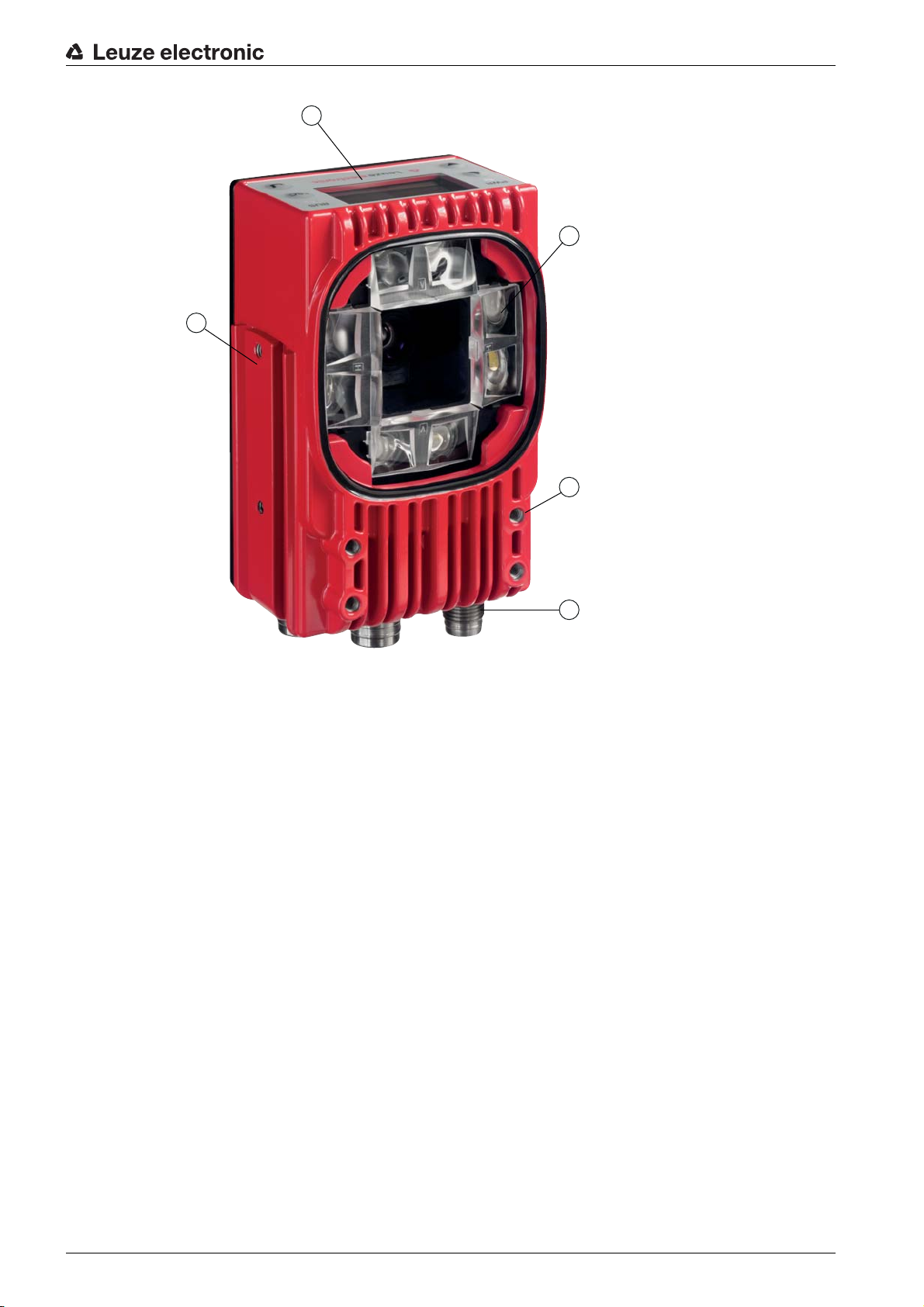
1 Display and control panel
2 Camera and lighting unit
3 M4 mounting thread
4 Electrical connections
5 Fastening groove
Figure 3.1: Device construction
Markings
The smart camera detects the following markings:
• Hole: dark marking on light background
• Reflector: light marking on dark background
Which markings (hole or reflector) need to be present in the crossbeam of the rack is dependent on the
working distance and the crossbeam:
Rack Near
•
•
Rack Far
3.1.2 Performance characteristics
: compartment fine positioning on hole or reflector
: compartment fine positioning on reflector
The most important performance characteristics of the smart camera:
• Positioning accuracy up to ± 2 mm
• Reading distance 250 mm to 1900 mm
• Integrated IR illumination (850 nm infrared LED)
• Integrated display with control panel for alignment and for fast teaching of the position marking (hole
or reflector).
• Measurement value output:
• 4 digital outputs
• Ethernet
Leuze electronic LSIS 472i 9
Page 10
• Optionally via MA 2xxi modular connection unit
3
2
1
• Interfaces:
• RS 232 and Ethernet TCP/IP
• PROFINET, PROFIBUS, CANopen, DeviceNet and EtherCat via MA 2xxi modular connection unit
• Alignment via display and webConfig tool
• Diagnostics in Process mode through image transfer via FTP transfer
• Optional model with heating for use to -35 °C
3.1.3 Accessories
Device description
Special accessories are available fo
smart camera:
• Ready-made connection and interconnection cables for M12 connectors
• Mounting devices for precise mounting
• Reflectors for
Rack Near
3.1.4 Device model with heating
The device is optionally available as a model with integrated heating
installed ex works.
The heating consists of two parts:
• Optics glass heating
• Housing heater
Features of the integrated heating:
• Extends the application range to -35 °C
• Supply voltage: 24 VDC ± 20 %
• Required conductor cross-section for the power supply: At least 0.75 mm
Thus, it is not possible to use ready-made cables.
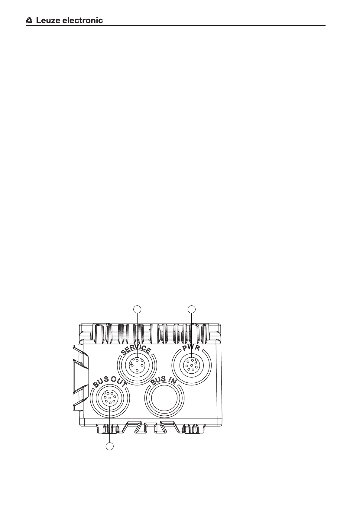
3.2 Connection technology
The device is connected using variously coded M12 connectors.
r the smart camera. The accessories are optimally matched to the
and
Rack Far
compartment depths
. In this case, heating is permanently
2
1 SERVICE: host and service interface (Ethernet); M12 socket (D-coded)
2 PWR: supply voltage (18 V … 30 VDC), IO1 … IO4; M12 plug (A-coded)
3 BUS OUT: RS 232 interface, IO5 … IO8; M12 socket (A-coded)
Figure 3.2: Electrical connections
Leuze electronic LSIS 472i 10
Page 11
Ready-made cables are available for all connections; see chapter 14.2 "Cables-Accessories".
2
1
3
4
5
6
NOTICE
Shielding connection
The shielding connection is done via the M12 connector housing
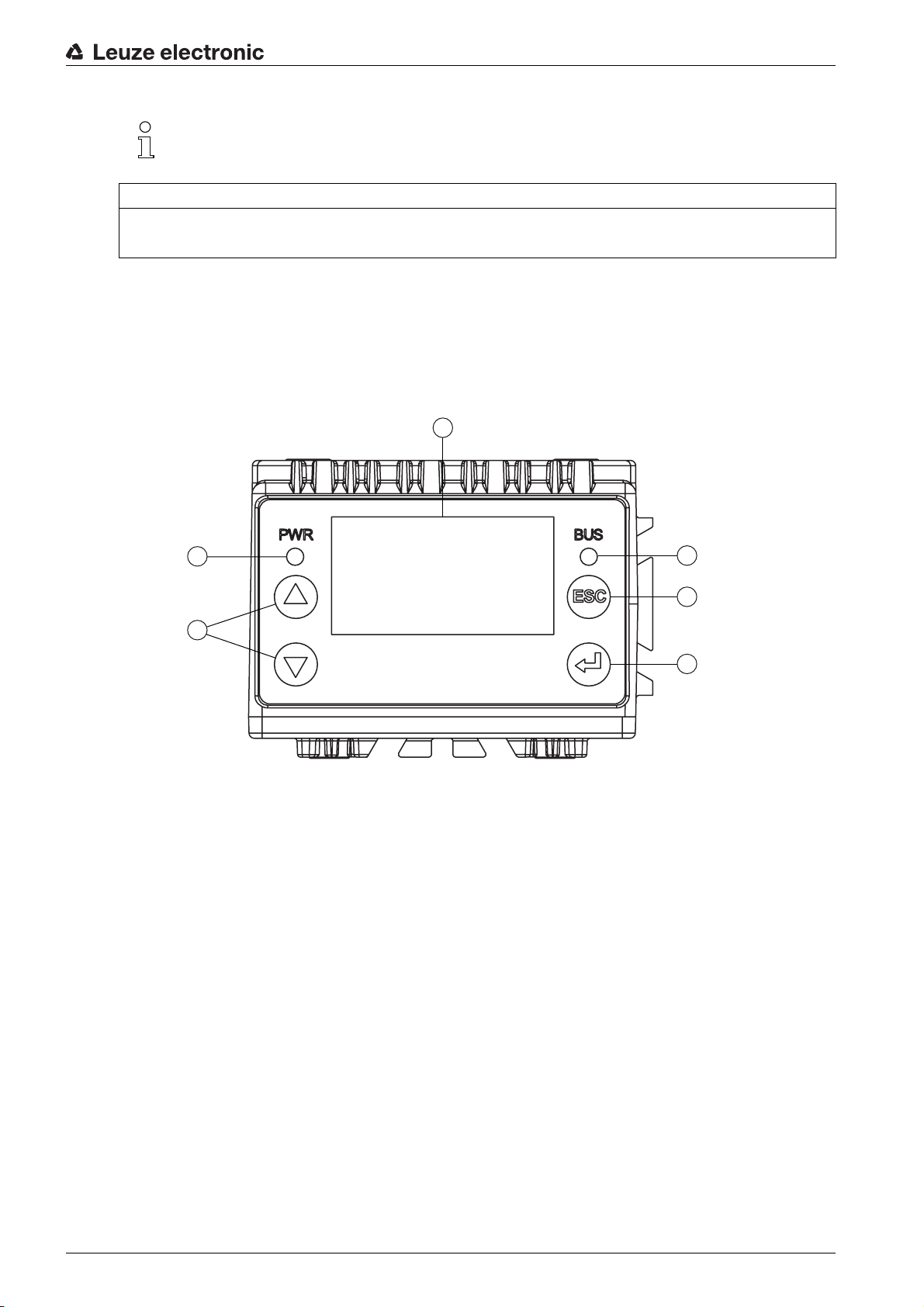
3.3 Indicators and operational controls
The device is equipped with the following indicators and operational controls:
• Two LED indicators
• Four control buttons
• Monochromatic display
Device description
1LED PWR
2 Navigation buttons
3LED BUS
4 Escape button
5 Enter button
6 Display
Figure 3.3: Indicators and operational controls
Leuze electronic LSIS 472i 11
Page 12
3.3.1 LED indicators
ESC
Table 3.1: Meaning of the LED indicators
LED Color, state Description
Device description
LED
PWR
LED
BUS
Off Device is switched off
• no supply voltage
Green, flashing Device is being initialized
• Supply voltage connected
• Self test running
• Initialization running
Green, continuous light Process mode
• Initialization finished
• Self test successfully finished
• Position display activated
Orange, continuous
light
Service mode
• Alignment via display
• Configuration via Ethernet service interface
• Configuration via the webConfig tool
Red, flashing Warning set
• Inspection mode
• Temporary operating fault
Red, continuous light Device error
Off No supply voltage
Green, flashing Bus initialization, a pulse
3.3.2 Control buttons
The display is controlled via the control buttons. You can call up var
control buttons (e.g., the IP address of the device) or make adjustments in the application; e.g., teach-in.
• - Scrolling through functions (upwards)
• - Scrolling through functions (downwards)
• – Escape button: exit the menu item, move up one menu level
• – Enter button: select function, confirm/enter value
Navigating within the menus
Use the navigation buttons to move through the menu.
Activate the desired selection with the enter button .
Press the escape button to move up one menu level.
Selecting options
Set the desired option with the navigation buttons and the enter button .
3.3.3 Display
Green, continuous light Device ready for communication
Red, flashing Communication error
ious pieces of information via the
ESC
Display functions
The following functions can be displayed and activated in the display:
• Device information
Leuze electronic LSIS 472i 12
Page 13

• Device type
1
SW:
•
•
•
• Status displays
• Status display of the switching inputs/outputs
• Display of warnings and errors
• Status information for the device interfaces
• Target/actual position deviation for X- and Y-coordinates in mm
•Statistics
Statistics data for the smart camera:
•
•
•
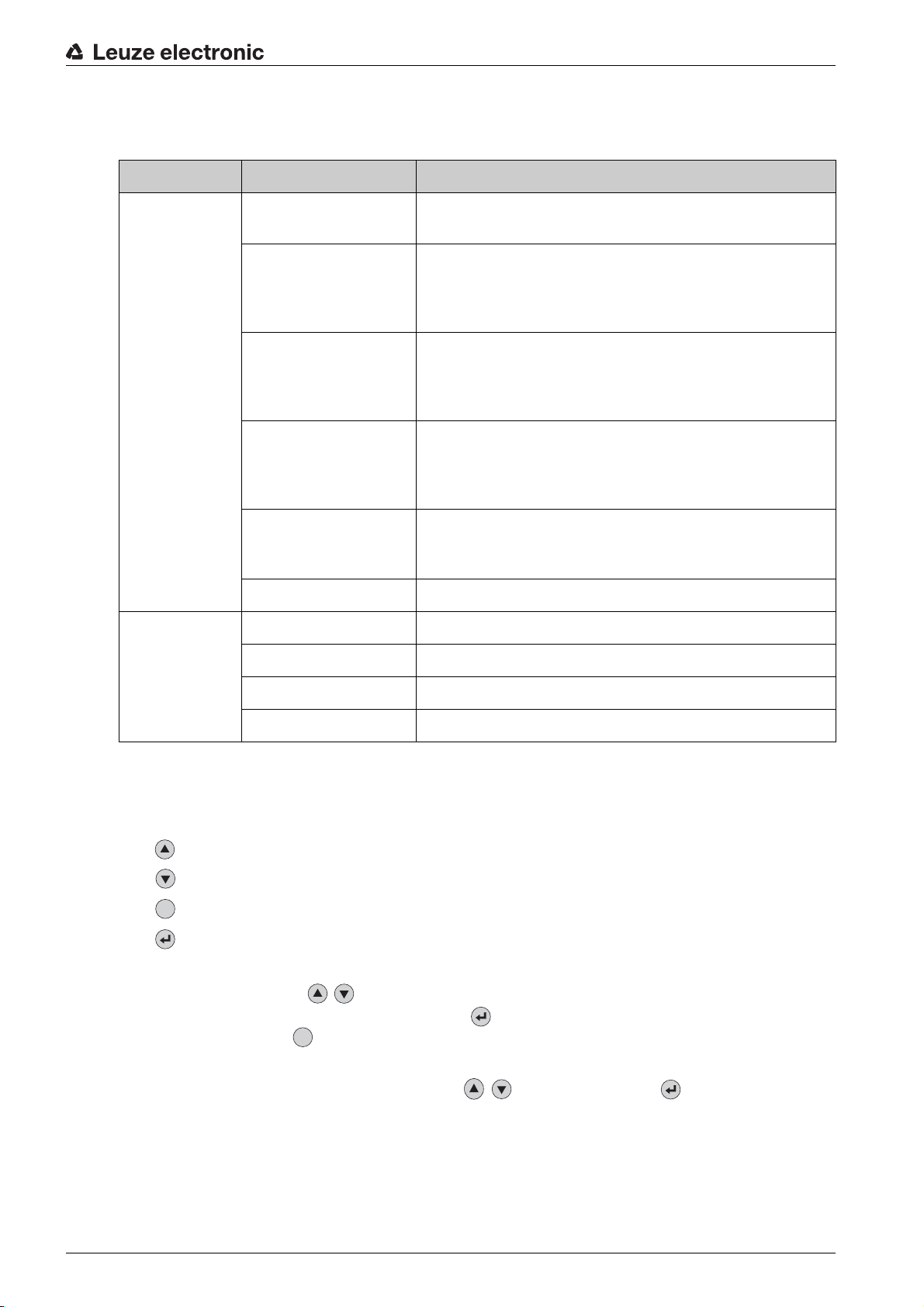
• Position display of the marking (hole or reflector)
Software version
HW:
Hardware version
SN:
Serial number
Tested
Number of check program runs since the last time the counter was reset
OK
Number of successful check program runs
NOK
Number of unsuccessful check program runs
Device description
1 Actual position of the marking within the capture range
Figure 3.4: Position display
• Parameter
•
Parameter handling
Lock and enable parameter entry on the display
Define password for enabling parameter entry
Reset parameters to factory settings
Display settings
•
Rotate the display 180°
Only possible with enabled parameter entry
Program selection
•
Activation of the check program via the display for compartment fine positioning:
Rack Far
•
Ethernet
Configuration of the host and service interface
• Language
Selection of the language used in the display:
German, English, Spanish, French, Italian
•Service
•
Status messages
Only for service purposes by Leuze electronic
Commissioning
•
Selection of the check program and position display for alignment; see chapter 8 "Commissioning"
Teaching-in of the position (teach); see chapter 8.3 "Teaching-in the position"
Rack Near
or
In Service mode, the device is decoupled from Process mode. Triggering via the switching inputs
Leuze electronic LSIS 472i 13
is not possible and the digital switching outputs are not set.
Page 14

Device description
Display during device start-up
During device start-up, a start-up display first appears which is briefly followed by the display with the
version information.
After the device starts up, the display shows the position display by default.
Leuze electronic LSIS 472i 14
Page 15
4 Functions
4.1 Functionality of the device
Compartment fine positioning is used for the detection of so-called hole positions (hole or reflector) that
are set into crossbeams of the high rack.
Functions
• Two different hole positions can be detected,
A check program is stored on the device for each detection position.
The distance between the rack profiles and the lens cover of the device can be specified for each
hole position.
• The control uses a signal that is constantly applied at digital switching inputs IO2 and IO3 to determine which check program is active; see chapter 4.4 "Process sequence".
4.2 Check programs
The
Rack Near
measuring tool in the check program are used for this purpose.
• With activation, compartment fine positioning for the
started or stopped via digital switching input I01.
Figure 4.1: Display of the detected hole position
• Digital switching outputs IO5 … IO8 signal whether the device is within the scan area for
Rack Far
or
whether the high-bay storage device is positioned too far to the left or right and/or too far up or down
relative to the hole position is displayed.
and
in relation to the hole position. Whether or not compartment fine positioning is correct or
Rack Far
Rack Near
check programs detect the respective hole position. A BLOB tool and a
and
Rack Far
Rack Near
or
Rack Far
.
check program is
Rack Near
Figure 4.2: Switching outputs IO5 … IO8 activated
Digital switching outputs IO5 … IO8 are permanently on as long as the control performs compartment fine positioning via the device.
• To compensate for the difference in position between loading position and unloading position of the
high-bay storage device, a shift of the coordinate origin is defined for the current check program by
entering an offset value.
On delivery, two check programs are set up in the device for
programs are optimized as follows:
Rack Near
•
Distance: 450 mm
Hole diameter: 15 mm
Rack Far
•
Distance: 1850 mm
Hole diameter: 15 mm
Leuze electronic LSIS 472i 15
Rack Near
and
Rack Far
. These check
Page 16
4.3 Diagnostics – image transfer
For diagnostics, the smart camera images can be stored (parallel to the check program procedure) in the
ring buffer.
• Saving the images in the ring buffer is started (IO4=1) and ended (IO4=0) via digital switching input
IO4.
• A maximum of 14 images are stored in the ring buffer, with the oldest images being overwritten once
the buffer is full.
14 images in the ring buffer correspond to approx. 500 ms of positioning.
The images can be transferred to an FTP server via FTP for diagnostics:
• To transfer the images, an M12 Ethernet connection cable must be connected between the smart
camera and a PC or laptop as FTP server.
Alternatively, the smart camera can be connected to a network in which the FTP server can be
accessed.
• Data transmission via FTP:
• The FTP access data must be entered in the webConfig tool.
• Data transmission via FTP must be activated in the webConfig tool.
The images are not transferred from the ring buffer until after the trigger signal (IO1=0) has been
reset.
• Upon conclusion of diagnostics, data transmission via FTP must be deactivated in the webConfig
tool.
The M12 Ethernet connection cable can be removed after completing diagnostics.
• The FTP access data can be stored in the smart camera for later diagnostics.
• Details on the settings in the webConfig tool: see chapter 9 "Extended configuration –
Leuze electronic webConfig tool".
Functions
4.4 Process sequence
Prerequisite: The high-bay storage device knows the hole positions for
NOTICE
Incoming signals are ignored while changing the check programs!
While the check programs are being changed internally, additional incoming signals are ignored,
including the trigger signals.
The internal changeover of the check programs lasts up to 300 ms.
• Shortly before reaching the target position (capture range), a permanently applied signal at switching
inputs IO2 and IO3 specifies the check program for the device.
Program 1: IO2=0 and IO3=0, corresponds to
Program 2: IO2=0 and IO3=1, corresponds to
• The control activates the test procedure, i.e., compartment fine positioning, by setting switching input
IO1=1.
Tool evaluation, i.e., execution of the check program, is started beginning at this point in time. Digital
switching outputs IO5 … IO8 are output statically as long as the specified hole position is detected in
the respective tool.
• At the end of check program execution, a check for the presence of the activation signal (IO1=1) is
performed.
If the activation signal is still present, the check program is immediately executed again.
• If the activation signal (IO1) is reset while a check program is being executed (IO1=0), this check
continues to run. Switching outputs IO5 … IO8 are then set to 0.
• If switching output IO5 … IO8=1 and the high-bay storage device has reached the target position,
loading or unloading is started.
• Parallel to the test procedure, switching input IO4 can be used to start (IO4=1) or end (IO4=0) the
saving of images in the ring buffer. The user can thereby separate the check program procedure
from the image.
Rack Near
Rack Far
Rack Near
and
Rack Far
.
Leuze electronic LSIS 472i 16
Page 17
Functions
1
2
3
4
5
6
t
t
t
t
7
7 78
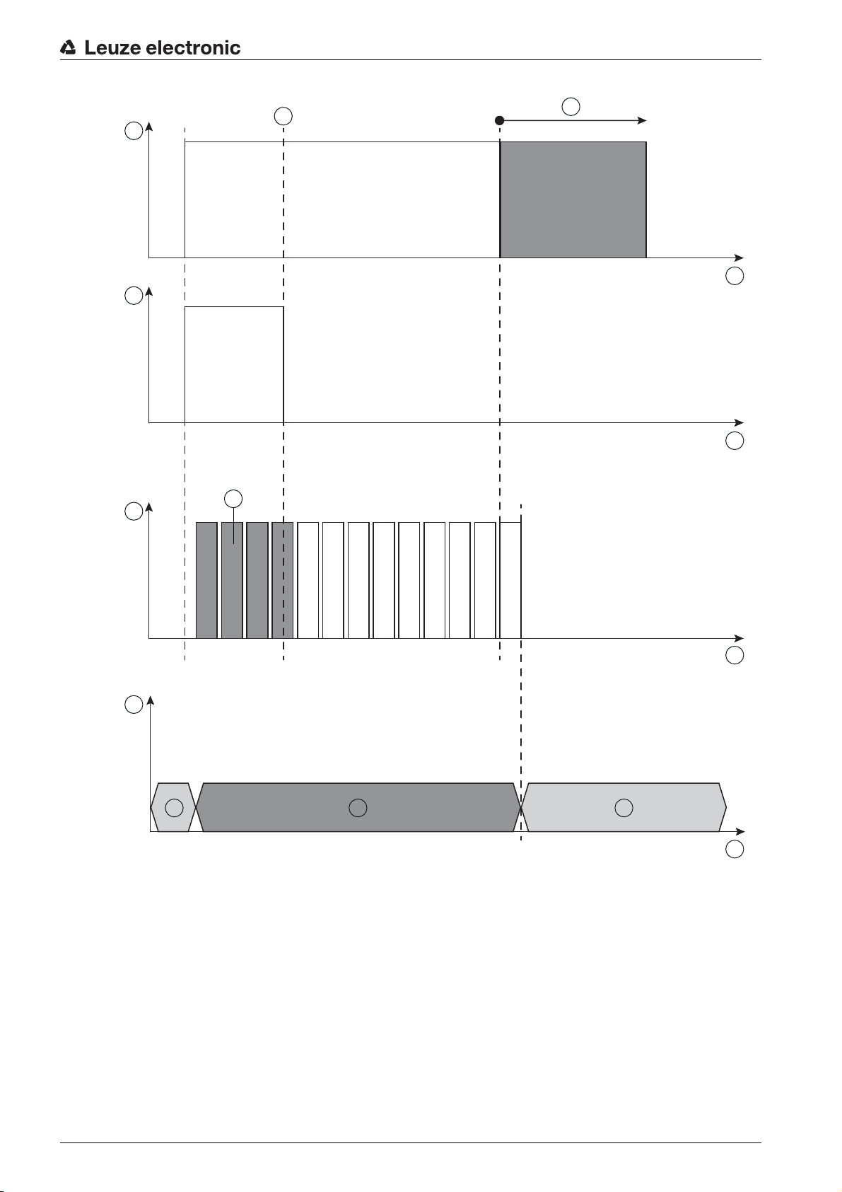
Figure 4.3: Process sequence
Leuze electronic LSIS 472i 17
1 Activation: IO1
2 Image acquisition in ring buffer: IO4
3 Program runs
4 State IO5 … IO8
5 IO5 … IO8 stable
6 Image transfer via FTP
7(3) Images that are written in the ring buffer
7(4) IO5 … IO8: output inactive (low)
8 IO5 … IO8: output active (high), tool result
Page 18

5 Applications
Following rough positioning, the LSIS 472i smart camera is used for the optical, contactless, compartment
fine positioning of a high-bay storage device in X- and Y-direction. It is possible to use just one camera in
single-deep and double-deep pallet high-bay warehouses.
Applications
Figure 5.1: Compartment fine positioning of a high-bay storage device in a double-deep pallet high-bay
warehouse
Leuze electronic LSIS 472i 18
Page 19

6 Mounting
The device can be mounted in the following ways:
• Mounting using a mounting device on the fastening grooves on the rear of the device or on the narrow side of the device.
• BT 56: Mounting on a rod
• BT 59: Wall mounting
• Mounting via M4 mounting thread:
• on the rear side of the device
• on the front side of the device
• on the narrow side of the device
6.1 Installation instructions
NOTICE
Observe during mounting!
Make certain that the required environmental conditions (humidity, temperature) are maintained.
Affix the markings for compartment fine positioning according to the working distance:
Rack Near
Rack Far
Make certain that the area behind a hole is not obstructed.
With closed profiles, only reflectors may be used as markings.
There must not be a light source behind a hole.
Avoid glossy, reflective surfaces behind the holes.
The surface surrounding a hole must reflect diffusely, i.e., no glossy surfaces.
Avoid interfering contours in the camera's field of view, e.g., stamped numbers.
Make certain that there is only one marking (hole or reflector) in the capture range of the smart camera.
Screw heads with identical diameter must not be located in the capture range of the smart camera.
Make certain that the lens cover of the smart camera is oriented parallel to the marking (hole or reflec-
tor).
Make certain that the marking (hole or reflector) is located as close to the middle of the capture range
of the smart camera as possible.
Make certain that the camera window is not soiled, e.g., by leaking fluids, abrasion from boxes or res-
idues from packaging material.
: hole or reflector
: reflector only
Mounting
6.2 Mounting with BT 56 mounting device
Mounting with a BT 56 mounting device is intended for rod mounting. For ordering information, see
chapter 14.3.
Mount the BT 56 on the rod with the clamp profile (system-side).
Mount the device with its fastening grooves on the clamping jaws of the BT 56 with limit stop at end.
Secure the device with the M6 screw terminal.
Maximum tightening torque for the M6 screw terminal: 8 Nm
6.3 Mounting with BT 59 mounting device
Mounting with a BT 59 mounting device is intended for wall mounting. For ordering information, see
chapter 14.3.
Mount the BT 59 mounting device on the system side with M8 fastening screws (included in delivery
contents).
Mount the device with its fastening grooves on the clamping jaws of the BT 59 with limit stop at end.
Secure the device with the M6 screw terminal.
Leuze electronic LSIS 472i 19
Page 20

Maximum tightening torque for the M6 screw terminal: 8 Nm
6.4 BPS mounting with M4 fastening screws
Mount the device on the system with M4 fastening screws (not included in delivery contents).
Max. tightening torque of the fastening screws: 2 Nm
Location and thread depth of the mounting thread: see figure 13.1
Mounting
Leuze electronic LSIS 472i 20
Page 21

7 Electrical connection
3
2
1
7.1 Overview
The electrical connection of the device is performed using M12 connectors.
Electrical connection
1 SERVICE: host and service interface (Ethernet); M12-socket (D-coded)
2 PWR: supply voltage (18 V … 30 VDC), IO1 … IO4; M12 plug (A-coded)
3 BUS OUT: RS 232 interface, IO5 … IO8; M12 socket (A-coded)
Figure 7.1: Position and designation of the M12 connections
For all connections (connection cable, interconnection cable, etc.), use only the cables listed in
the accessories (see chapter 14.2 "Cables-Accessories").
CAUTION
Safety Notices!
Before connecting the device please ensure that the supply voltage matches the value printed on the
nameplate.
Only allow competent persons to perform the electrical connection.
The shielding connection is done via the M12 connector housing.
Ensure that the functional earth (FE) is connected correctly.
Fault-free operation is only guaranteed if the functional earth is connected properly.
All electrical disturbances (EMC couplings) are discharged via the functional earth connection.
If faults cannot be rectified, take the device out of operation. Protect the device from accidentally being
started.
NOTICE
UL applications
For UL applications, use is only permitted in class 2 circuits in accordance with the NEC (National Elec-
tric Code).
Leuze electronic LSIS 472i 21
Page 22

NOTICE
FE
1
2
3
4
5
6
7
8
Protective Extra-Low Voltage (PELV)
The smart camera of the LSIS 4xxi series is designed in accordance with safety class III for supply by
PELV (protective extra-low voltage with reliable disconnection).
NOTICE
Degree of protection IP 65 / IP 67
Degree of protection IP 65 / IP 67 is only achieved with screwed-on connectors.
Connect the supply voltage (18 V … 30 VDC) to the PWR connection.
Connect switching inputs IO1 … IO4 to the PWR connection.
Connect switching outputs IO5 … IO8 to the BUS OUT connection.
Connect your RS 232 process interface to the BUS OUT connection.
Connect the Ethernet cable for configuration and diagnostics to the SERVICE connection.
7.2 PWR (supply voltage and switching inputs IO1 … IO4)
8-pin M12 plug (A-coded)
Electrical connection
Figure 7.2: Pin assignment of the PWR connection
Table 7.1: PWR pin assignment
Pin Designation Assignment
1 VIN Positive supply voltage +18 … +30 VDC
2 IO1 Switching input 1
• Activation - program start
• Function: reading gate start/stop
3 GND Negative supply voltage 0 VDC
4 IO2 Switching input 2
• Program selection 1
5 IO3 Switching input 3
• Program selection 2
6 IO4 Switching input 4
• Error image memory active
• Start: write images in ring buffer
7 NC Not connected
8 FE Functional earth
(Thread for M12
connector plug)
FE Connection cable shield
The shield of the connection cable is on the thread of
the M12 connector plug.
The thread of the M12 connector plug is part of the
metallic housing. The housing is at the potential of
Connection cables: see table 14.2
Leuze electronic LSIS 472i 22
the functional earth via pin 8.
Page 23

NOTICE
Maximum input current
The maximum input current of the switching inputs is 8 mA.
7.3 BUS OUT (RS 232 and switching outputs IO5 … IO8)
8-pin M12 socket (A-coded)
7
8
1
6
5
Electrical connection
2
3
FE
4
Figure 7.3: Pin assignment of the BUS OUT connection
Table 7.2: BUS OUT pin assignment
Pin Designation Assignment
1 IO5 Configurable switching output 1
Compartment fine positioning (-X)
2 IO6 Configurable switching output 2
Compartment fine positioning (+X)
3 GND Negative supply voltage 0 VDC
4 IO7 Configurable switching output 3
Compartment fine positioning (+Y)
5 IO8 Configurable switching output 4
Compartment fine positioning (-Y)
6 Rx Rx signal (RS 232)
7 Tx Tx signal (RS 232)
8 FE Functional earth
(Thread for M12
connector plug)
FE Connection cable shield
The shield of the connection cable is on the thread of
the M12 connector plug.
The thread of the M12 connector plug is part of the
metallic housing. The housing is at the potential of
the functional earth via pin 8.
Connection cables: see table 14.2
NOTICE
Maximum loading of the switching outputs
Do not load the switching outputs with more than 60 mA at +18 … +30 VDC.
The switching outputs are protected against short-circuit, overcurrent, overvoltage, excess temperature and transients.
NOTICE
Maximum cable length 10 m
Operation of the RS 232 interface is only permissible with shielded cables with maximum cable length
of 10 m.
Leuze electronic LSIS 472i 23
Page 24

7.4 SERVICE
3
4
1
2
2
1
3
4
1
8
4-pin M12 socket (D-coded)
Figure 7.4: Pin assignment of the SERVICE connection
Table 7.3: SERVICE pin assignment
Pin Designation Assignment
1 TD+ Transmit Data +
2 RD+ Receive Data +
3 TD- Transmit Data -
Electrical connection
(Thread for M12
connector plug)
FE Connection cable shield
The shield of the connection cable is on the thread of
the M12 connector plug.
The thread of the M12 connector plug is part of the
metallic housing. The housing is at the same potential as functional earth.
Connection cables: see table 14.2
Ethernet cable assignment
Figure 7.5: Cable assignments - SERVICE on RJ-45
Designed as shielded cable, max. length 100 m.
Pin (M12) Designation Pin/core color (RJ-45)
1 TD+ 1/yellow
2 RD+ 3/white
3 TD- 2/orange
4 RD- 6/blue
NOTICE
Self-configured cables for Ethernet connection!
The depicted core colors apply only for interconnection cables from Leuze electronic.
The depicted core colors are not compliant with EIA/TIA 568A and EIA/TIA 568B.
Ensure adequate shielding.
The entire interconnection cable must be shielded and earthed.
Leuze electronic LSIS 472i 24
The RD+/RD- and TD+/TD- wires must be stranded in pairs.
Use CAT 5 cable for the connection.
Page 25

8 Commissioning
Basic operation of the device is via a multi-language display and control buttons or via the webConfig
configuration tool.
For faster commissioning, the most important parameters for compartment fine positioning are set on a
connected PC/laptop via a configuration dialog in the webConfig tool.
Commissioning includes the mechanical alignment of the smart camera and the teaching-in of the position
via the display and control buttons as well as calibration, i.e., calibration of distance and marking size, via
the webConfig tool.
8.1 Commissioning the device
Electrically connect the smart camera and apply the supply voltage.
The smart camera starts up and the position display appears on the display.
Connect the smart camera to a PC/laptop and start the webConfig tool; see chapter 9 "Extended
configuration – Leuze electronic webConfig tool".
Make the settings for your application with the webConfig tool; see chapter 9.3.4 "Configure compart-
ment fine positioning".
Disconnect the smart camera from the PC/laptop and from the power source.
Mount the smart camera in your application; see chapter 6 "Mounting".
Electrically connect the smart camera in your application; see chapter 7 "Electrical connection".
Connect the supply voltage.
Mechanically align the smart camera with the marking via the display and control buttons; see
chapter 8.2 "Mechanically aligning the device via the display".
Commissioning
NOTICE
Adjusting compartment fine positioning with the webConfig tool!
To align via the display and the control buttons, the current configuration for compartment fine posi-
tioning must be set with the webConfig tool and be stored in the device; see chapter 9 "Extended
configuration – Leuze electronic webConfig tool".
Teach-in the position of the smart camera; see chapter 8.3 "Teaching-in the position".
Connect a PC/laptop to the smart camera and start the webConfig tool; see chapter 9 "Extended
configuration – Leuze electronic webConfig tool".
Calibrate the device for the current check program with the webConfig tool; see chapter 9.3.5 "Calibrat-
ing".
8.2 Mechanically aligning the device via the display
Prerequisites:
• The smart camera is correctly mounted; see chapter 6 "Mounting".
The smart camera is correctly connected; see chapter 7 "Electrical connection".
The application data is set via the webConfig tool; see chapter 9.3.4 "Configure compartment fine
positioning".
• The lens cover of the smart camera is aligned parallel to the marking (hole or reflector).
• The marking (hole or reflector) is located as close to the middle of the capture range of the smart
camera as possible.
Use the navigation buttons to move through the menu. Activate the desired selection with
the enter button .
Press the navigation button three times.
Press the enter button to activate
Select
Select the check program for alignment (
Leuze electronic LSIS 472i 25
Commissioning
.
Service
mode.
Rack Near
or
Rack Far
).
Page 26

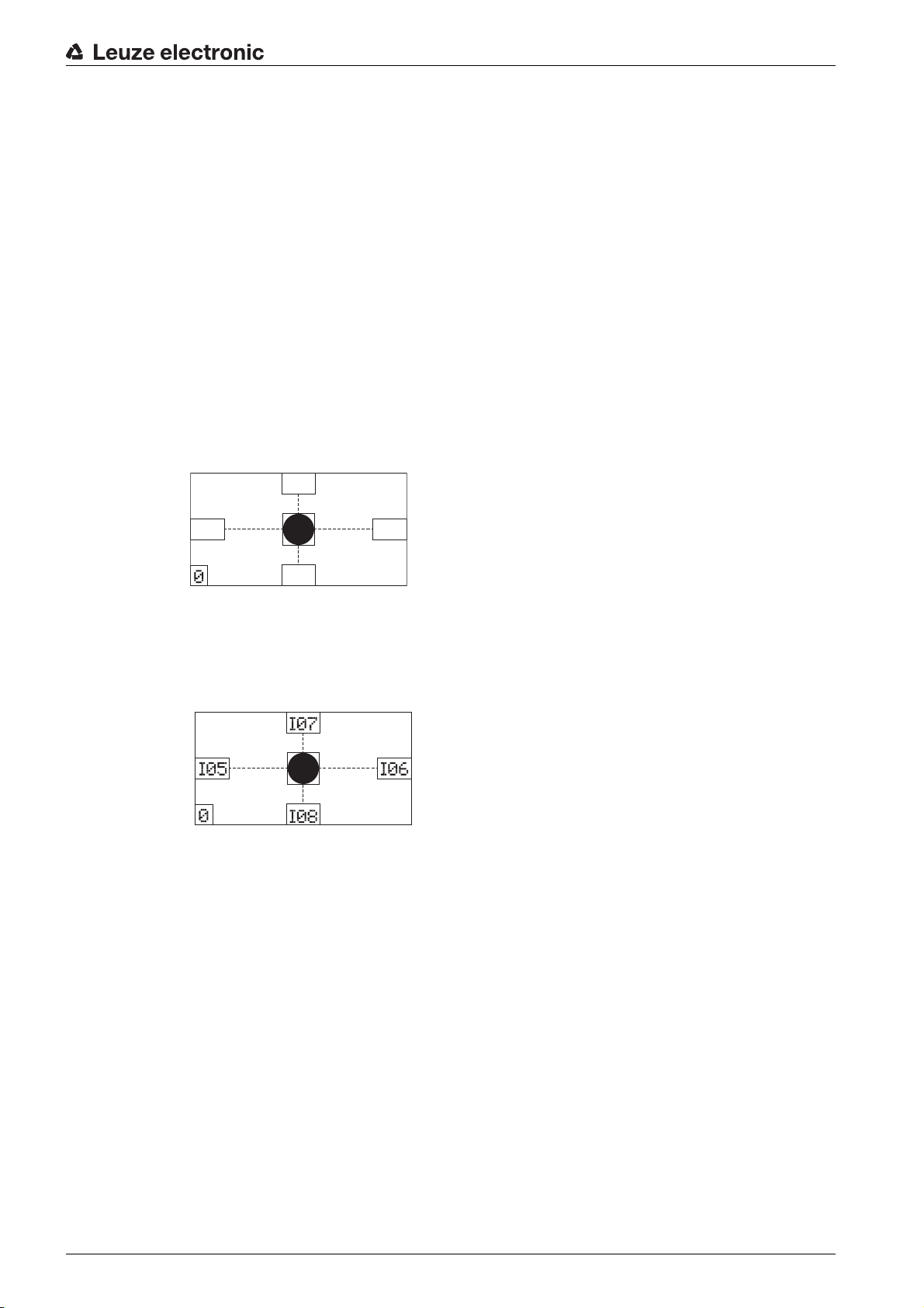
Commissioning
1
2
34
1
1 Actual position of the marking
2 Status signaling of switching outputs IO5 … IO8
3 Capture range
4 Display of the active check program
Rack Near
0 for
1 for
Rack Far
Figure 8.1: Indicators in the display
• A semicircle visible in the position display indicates that the marking is in the field of view of the
device but not in the capture range.
Turn the device towards the semicircle.
1
1 Marking indicator outside of capture range
Figure 8.2: Marking in the field of view, but not in the capture range
• A black dot in the position display indicates that the marking is in the capture range of the device.
The device is not yet optimally aligned.
1 Marking indicator in the capture range
Figure 8.3: Marking in the capture range
• If the marking is not in the field of view of the device (no marking indicator), the device must be
mechanically repositioned.
Align the device until the marking indicator (black dot) is exactly in the square in the middle of the dis-
play.
Leuze electronic LSIS 472i 26
Page 27

1
ESC
1 Marking indicator
Figure 8.4: Device aligned with the marking
Commissioning
Press the escape button to exit
If necessary, teach-in the position for fine adjustment; see chapter 8.3.
Calibrate the device for the current check program with the webConfig tool; see chapter 9.3.5 "Calibrat-
ing".
8.3 Teaching-in the position
For fine adjustment and, alternatively, for exact mechanical alignment via the
user can teach-in the position of the device via the display.
While teaching-in the position (teach), a position correction of the coordinate system of the capture range
is performed.
Teaching-in of the position is performed separately for each distance.
Reteaching of the position is not performed for a different hole geometry or for different exposure/
focal settings.
NOTICE
Align the device before teaching-in the position!
The device must be roughly aligned before teaching-in the position.
The capture range must not exit the field of view.
For the
as the capture range.
Rack Near
distance, the teach range is nearly zero since the field of view is almost the same
Service
mode.
Commissioning
menu, the
Use the navigation buttons to move through the menu. Activate the desired selection with
the enter button .
To teach the position for the current alignment, the marking (hole or reflector) must be located within the
capture range; see figure 8.3.
Service
In
Select the distance for teaching-in (
Select the
Select
If the
Teach-in
mode, select
Teach-in
Teach-in
.
Commissioning
menu.
menu option is crossed out in the
.
Rack Near
or
Rack Far
Teach-in
).
menu, teaching-in of the position is not possible.
Mechanically realign the device; see chapter 8.2 "Mechanically aligning the device via the display".
Possible causes:
• The marking is not in the capture range of the device.
• The limits of the new capture range ascertained by teaching in are not completely in the field of view.
Exit the
To do this, press the Escape button .
Leuze electronic LSIS 472i 27
Commissioning
menu.
ESC
Page 28

The capture range with the new coordinate origin ascertained by teaching in must be completely
ESC
in the field of view.
Calibrate the device for the current check program with the webConfig tool; see chapter 9.3.5 "Calibrat-
ing".
8.4 Parameter enable
During process mode parameters can only be viewed. If parameters are to be changed and for configuration settings via the display, parameter enabling must be activated.
Parameter enabling is activated by default.
If parameter enabling is deactivated, you must activate parameter enabling for the configuration settings
via the display.
Use the navigation buttons to move through the menu. Activate the desired selection with
the enter button .
Commissioning
In the
Parameter
Select the
Select the
menu, select the
Parameter enable
ON
option and press the enter button .
Parameter handling
option.
option.
The PWR LED illuminates orange. The device is in Service mode and you can set the configuration parameters via the display.
Press the Escape button to enter the main menu.
Leuze electronic LSIS 472i 28
Page 29

Extended configuration – Leuze electronic webConfig tool
IP
00:15:7B:20:00:15
DDLS 508i MAC
Name
9 Extended configuration – Leuze electronic webConfig tool
The smart camera can be operated and configured by means of the integrated webConfig tool via the
Ethernet service interface.
With the Leuze electronic webConfig tool, an operating-system independent, web-technology based,
graphical user interface is available for the configuration.
The webConfig tool can be run on any Internet-ready PC. The webConfig tool uses HTTP as communication protocol and the client-side restriction to standard technologies (HTML, JavaScript and AJAX) that are
supported by modern browsers.
The webConfig tool is offered in the following languages:
German, English, French, Italian, Spanish
9.1 Establishing an Ethernet connection
The Ethernet connection is used as the host interface and for configuring the device via a PC with a
browser.
In order for the PC and the smart camera to communicate with one another, both devices must
be on the same subnet and have different network addresses.
Address Link Label
The “Address Link Label” is an additional stick-on label that is affixed to the device.
Figure 9.1: Example of an “Address Link Label”; the device type varies depending on series
• The “Address Link Label” contains the MAC address (Media Access Control address) of the device
and offers the possibility to enter the IP address and the device name by hand.
The area of the “Address Link Label” on which the MAC address is printed can be separated from the
remainder of the stick-on label if necessary by means of the perforation.
• To use, the “Address Link Label” is peeled from the device and can be affixed in the installation and
layout diagrams to designate the device.
• Once affixed in the documents, the “Address Link Label” establishes a unique reference between
mounting location, MAC address or device, as well as the corresponding control program.
The time-consuming searching, reading, and manually writing down of the MAC addresses of all
devices installed in the system are eliminated.
Each device with Ethernet interface is uniquely identified via the MAC address assigned during
production. The MAC address is also listed on the name plate of the device.
If multiple devices are commissioned in a system, the MAC address of each installed device
must be correctly assigned, e.g., during programming of the control.
Connecting smart camera to a PC/laptop without network
Check the network address of the smart camera.
Leuze electronic LSIS 472i 29
On the display, select
Note the values for
Set the network address on the PC/laptop (example for Windows7).
Status > Network settings
Addr
and
Mask
.
.
Page 30

Log in as administrator.
Select
Select
Select
Set the
Start > Control Panel > Network and Internet > Network and Sharing Center
LAN connection
Internet Protocol Version 4 (TCP/IPv4)
IP address
The IP address of the PC/laptop must not be identical to the IP address of the smart camera.
Example: IP address of the smart camera: 192.168.060.101
IP address of the PC/laptop: 192.168.060.111
Set the subnet mask of the PC/laptop to the same value as on the smart camera.
Example: 255.255.255.0
Confirm all of the settings dialogs with [OK] or [Close].
Connect the SERVICE interface of the smart camera directly to the LAN port of your PC/laptop.
9.2 Start webConfig tool
Prerequisite: IP address and subnet mask for the LAN connection with the device are set correctly.
Connect the operating voltage to the device.
Connect the SERVICE interface of the device to the PC.
The connection to the SERVICE interface of the device is made via the LAN port of the PC.
Start the webConfig tool via your PC's Internet browser with IP address 192.168.60.101 or with the IP
address set by you.
192.168.60.101 is the standard Leuze electronic service address for communication with the smart
camera of the LSIS 4xxi series.
The webConfig start page is displayed on your PC.
and right-click to open the
of the PC/laptop.
Extended configuration – Leuze electronic webConfig tool
.
Properties
dialog.
and click on the [Properties] button.
Changing the operating mode (
Process
-
Service
) (upper left)
Figure 9.2: The start page of the webConfig tool
The user interface of the webConfig tool is largely self-explanatory.
The webConfig tool is completely contained in the firmware of the device.
The pages and functions of the webConfig tool may appear and be displayed differently depend-
ing on the firmware version.
Leuze electronic LSIS 472i 30
Page 31

Clearing browser history
The cache of the Internet browser is to be cleared if different device types or devices with different firmware
were connected to the webConfig tool.
Delete cookies and temporary Internet and website data from the browser cache before starting the
webConfig tool.
Example for Internet Explorer 10:
Tools > Delete browsing history > [Delete]
Note limit of Firefox sessions for version 17.0 and higher
If the limited number of Firefox sessions is exceeded, it may no longer be possible to address the device
via the webConfig tool.
Do not use the refresh functions of the Internet browser:
[Shift] [F5] or [Shift] + mouse click
9.3 Short description of the webConfig tool
The menus and dialog boxes of the webConfig tool are intuitive to operate and offer help texts and tool tips.
9.3.1 Operating modes
Extended configuration – Leuze electronic webConfig tool
For configurations with th
•
Process
The device is connected to the control.
• The process communication to the control is activated.
• The switching inputs/outputs are activated.
• The configuration cannot be changed.
PROCESS
•
CONFIGURATION
•
•
Service
• The process communication to the control is interrupted.
• The switching inputs/outputs are deactivated.
• The configuration can be changed.
PROCESS
•
CONFIGURATION
•
9.3.2 Configuration via the we
Use webConfig tool to set u
Select the check program; see chapter 9.3.3.
Configure compartment fine positioning for fast commissioning; see chapter 9.3.4.
Calibrate the device; see chapter 9.3.5.
Configure the image acquisition; see chapter 9.3.6.
Define the changeover of the check programs; see chapter 9.3.9.
Configure the BLOB analysis; see chapter 9.3.7.
Configure the measurement; see chapter 9.3.8.
Configure the digital switching input/outputs; see chapter 9.3.10.
Assign measurement values to the digital switching outputs; see chapter 9.3.11.
Activate the marking display on the display; see chapter 9.3.12.
Configure the output via an FTP connection; see chapter 9.3.13.
Configure the output via an Ethernet connection; see chapter 9.3.14.
function available.
function not available.
e webConfig tool, you can switch between the following operating modes:
function not available.
function available.
bConfig tool
p the device:
Leuze electronic LSIS 472i 31
Page 32

NOTICE
Configuration changes only in the
Changes made using the
mode.
9.3.3 Selecting the check program
Service
operating mode!
CONFIGURATION
Extended configuration – Leuze electronic webConfig tool
function can only be performed in the
Service
operating
There is a check program stored on the device for the detection
positions.
Select
The
CONFIGURATION > PROGRAMS
Overview of Check Programs
.
dialog is displayed.
of both the
Rack Near
and
Rack Far
hole
Figure 9.3:
Select the check program that you would like to activate (
Table 9.1: Overview of digital inputs for check programs
Digital input IO2 Digital input IO3 Selection ID Check program
000
101
0 1 2 Not defined
1 1 3 Not defined
9.3.4 Configure compartment fine positioning
To commission more quickly, you can
and
Near
Alternatively, you can make the configuration settings for compartment fine positioning manually; see
chapter 9.3.6.
Overview of Check Programs
Rack Far
The configuration for compartment fine positioning for faster commissioning is only available if
the device is directly connected to the PC/laptop.
) via a configuration dialog.
Rack Near
or
Rack Far
).
Rack Near
Rack Far
set the most important parameters for the check programs (
Rack
Leuze electronic LSIS 472i 32
Page 33

Extended configuration – Leuze electronic webConfig tool
Select
Click on the [Configure compartment fine positioning] button.
CONFIGURATION > PROGRAMS
.
Figure 9.4:
Enter the type and diameter of the marking.
Enter the distance between rack profile and lens cover of the device.
Enter the positioning accuracy for the active check program.
The positioning accuracy is determined over a rectangular positioning area depending on the diameter
of the marking. If the device sees the marking within this area, positioning of the high-bay storage device
is concluded (I05 … IO8 = 1).
Example:
• Diameter of the marking: 15 mm
Positioning accuracy X: 5 mm
Positioning accuracy Y: 5 mm
If the device sees the marking within an area of 25 mm x 25 mm around the center of the marking, all
switching outputs switch to 1.
Enter the offset values for the active check program.
The offset can be used to enter a deviation of the positioning relative to the middle of the marking, e.g.,
to take into account the difference in positioning between loading position and unloading position of the
high-bay storage device.
Confirm all entries with [OK].
Configure compartment fine positioning
For a single-depth warehouse, enter the same distance under
dialog
Rack Near
and
Rack Far
.
9.3.5 Calibrating
During device calibration, the measurement distance is calibrated with the diameter of the marking.
Select
Select the active check program (
Select
The
Leuze electronic LSIS 472i 33
CONFIGURATION > PROGRAMS
Rack Near
.
or
Rack Far
CONFIGURATION > PROGRAM > Tools > Calibration
Tool configuration – Calibration
dialog is displayed.
).
.
Page 34

Extended configuration – Leuze electronic webConfig tool
Figure 9.5:
NOTICE
Recalibration required if the measurement distance changes!
If the distance for the check program (
tion must be adjusted.
Calibrate via the point detectors if necessary.
Enter the diameter of the marking (hole or reflector) in the selection list [Calibration block length].
Click on the [Accept values] button.
Setting the offset
For the current check program, you can set additional distances (offsets) for the positioning. By means of
the offset value, it is possible to detect, e.g., the position difference between loading position and unloading
position of the high-bay storage device.
• If the offset values are 0, the smart camera positions the high-bay storage device exactly on the
marking.
• If offset values are set, the control signals a corresponding position deviation.
Example: with offset Y = 20 mm, the high-bay storage device is positioned 20 mm below the marking.
Tool configuration – Calibration
dialog
Rack Near
The offset is not visualized in the image.
or
Rack Far
) changes in the application, the calibra-
Select
Select the active check program (
Select
The
Leuze electronic LSIS 472i 34
CONFIGURATION > PROGRAMS
Rack Near
CONFIGURATION > PROGRAM > Tools > Calibration > Offset
Tool configuration – Offset
dialog is displayed.
.
or
Rack Far
).
.
Page 35

Extended configuration – Leuze electronic webConfig tool
Figure 9.6:
9.3.6 Configuring image acquisition
As an alternative to configuring compartment fine positioning for faster commissioning (see chapter 9.3.4),
you can make the configuration settings for compartment fine positioning manually.
Select
Select the active check program (
Select
The
Image acquisition – Attributes
Tool configuration – Offset
CONFIGURATION > PROGRAMS
CONFIGURATION > PROGRAM > Tools > Image acquisition
dialog
.
Rack Near
dialog is displayed.
or
Rack Far
).
.
Figure 9.7:
Set the image acquisition attributes according to the requirements of the application.
Leuze electronic LSIS 472i 35
Image acquisition – Attributes
dialog
Page 36

NOTICE
Adjust exposure time and focus if the distance is changed!
If the distance for the check program (
time and focus must be checked or adjusted.
When adjusting the focus, the same value must be set for the
grams.
For two compartments with different distances, use the mathematical average of the distances as the
focal distance.
9.3.7 Configuring the BLOB analysis
Extended configuration – Leuze electronic webConfig tool
Rack Near
or
Rack Far
) changes in the application, the exposure
Rack Near
and
Rack Far
check pro-
The centroid of the marking for the display in the image is ascertained v
Select
Select the active check program (
BLOB segmentation
Select
The
CONFIGURATION > PROGRAMS
Rack Near
.
or
Rack Far
).
CONFIGURATION > PROGRAM > Tools > BLOB > Segmentation
BLOB segmentation
dialog is displayed.
ia the BLOB analysis.
.
Figure 9.8:
Set the attributes for BLOB segmentation according to the requirements of the application.
Under
Hole:
Reflector:
BLOB attributes
Select
The
BLOB prefiltering
Leuze electronic LSIS 472i 36
BLOB segmentation
The display for the marking must lie completely in the capture range (blue frame).
Binarization
, set the type of marking:
Dark objects
Bright objects
CONFIGURATION > PROGRAM > Tools > BLOB > Attributes
dialog is displayed.
dialog
.
Page 37

Extended configuration – Leuze electronic webConfig tool
Figure 9.9:
Area
Shape factor
Centroid X, Centroid Y
9.3.8 Configuring the measurement
Select
Select the active check program (
Select
The
Measurement - Testing
BLOB prefiltering
attribute: adjust the NOMINAL limit values if the geometry of the marking has changed.
attribute: adjust the NOMINAL limit values if the geometry of the marking has changed.
attributes: the limits of the centroid values must not be changed.
CONFIGURATION > PROGRAMS
CONFIGURATION > PROGRAM > Tools > Measurement > Testing
dialog
.
Rack Near
dialog is displayed.
or
Rack Far
).
.
Figure 9.10:
Define the limits for the measurement.
Leuze electronic LSIS 472i 37
Measurement - Testing
dialog
Page 38

Extended configuration – Leuze electronic webConfig tool
The MINIMUM values for
Maximum Y
NOTICE
Adjust limit values if the tolerance areas are changed!
If the tolerance areas change in the application, the limit values in the
must be checked and adjusted if necessary.
The minimum value for this application is 2 mm.
9.3.9 Defining changeover of the check programs
In Process mode, you can switch between the
Select
The
CONFIGURATION OF DIGITAL I/OS
correspond to the limits for the positioning accuracy X and Y.
CONFIGURATION > DEVICE > Digital I/Os > General parameters
Minimum Y
and
dialog is displayed.
Maximum X
Rack Near
and the MAXIMUM values for
Measurement - Evaluation
and
Rack Far
check programs.
.
Minimum X
dialog
and
Figure 9.11:
Activate the
inputs IO2 and IO3.
The signals for program selection on the inputs must currently be applied.
• If the signals are removed at the inputs while the
the device interprets this as a “logical low” pending signal and activates the check program with
selection ID 0 (
•If the
performed via a “program change” input.
Define the
The delay time defines the time that the input signals must be applied to the device before a change to
an edge results in a change of check program. The delay time protects against faulty activations since
it takes up to 300 ms for the check program to changeover.
For technical reasons, it is not possible to implement an immediate changeover (delay time = 0 ms). If
the delay time is set to 0 ms, the functionality is deactivated. This corresponds to unselecting the
matic program change
9.3.10 Configuring the digital sw
The digital switching inputs/outputs are configured for the active check pr
ration dialog.
Leuze electronic LSIS 472i 38
CONFIGURATION OF DIGITAL I/OS
Automatic program change
Near Rack
).
Automatic program change
checkbox for changing the check programs via digital switching
checkbox is not selected, the check program confirmation must be
Delay time - program selection input
checkbox.
itching inputs/outputs
dialog
Automatic program change
.
checkbox is selected,
ogram via the
DEVICE
Auto
configu-
-
Page 39

Extended configuration – Leuze electronic webConfig tool
Select
Select the active check program (
Select
The
CONFIGURATION > PROGRAMS
CONFIGURATION > DEVICE > Digital I/Os
CONFIGURATION OF DIGITAL I/OS
.
Rack Near
or
dialog is displayed.
Rack Far
.
).
Figure 9.12:
Set the configuration of the digital switching inputs/outputs according to the requirements of the appli-
cation.
Table 9.2: Factory settings of the digital switching inputs/outputs
IO port IO mode Function
IO1 Input Activation - program start
IO2 Input Program selection 1
IO3 Input Program selection 2
IO4 Input Error image memory active
IO5 … IO8 Output Programmable 1 … 4
9.3.11 Assigning digital switching outputs the measurement values
Check-program-specific assignment of tool results to the programmable digital switching outputs.
Select
Select the active check program (
Select
The
TOOL CONFIGURATION - Digital I/O
CONFIGURATION OF DIGITAL I/OS
Reading gate start/stop
Start writing images to ring buffer
Outputs for compartment fine positioning
CONFIGURATION > PROGRAMS
.
Rack Near
CONFIGURATION > PROGRAM > Tools > Output > Digital I/O
dialog is displayed.
or
Rack Far
dialog
).
.
Leuze electronic LSIS 472i 39
Page 40

Extended configuration – Leuze electronic webConfig tool
Figure 9.13:
TOOL CONFIGURATION - Digital I/O
dialog
For each switching output, select the desired measurement value that is to be output via the switching
output.
Click on the [Save changes] button.
The smart camera makes available digital switching outputs -X, +X, -Y, +Y. In addition, the status of these
switching outputs appears on the display.
The target position is located within a rectangular tolerance area. Depending on the X deviations and Y
deviations, the switching outputs are switched as follows.
•IO5=-X
• IO6=+X
• IO7=+Y
•IO8=-Y
Leuze electronic LSIS 472i 40
Page 41

Extended configuration – Leuze electronic webConfig tool
Figure 9.14: Switching of the switching outputs
9.3.12 Activating display of the target/actual deviation in the display
In order for the target/actual deviation for the marking to be shown in the display, the output must be activated via the Ethernet interface.
Select
Select the active check program (
Select
The
CONFIGURATION > PROGRAMS
Rack Near
.
or
Rack Far
CONFIGURATION > PROGRAM > Tools > Output > Display
TOOL CONFIGURATION - Display
dialog is displayed.
).
.
Leuze electronic LSIS 472i 41
Page 42

Extended configuration – Leuze electronic webConfig tool
Figure 9.15:
Select the
Click on the [Save changes] button.
9.3.13 Configuring the FTP output
Check-program-specific output of test results on the Ethernet interface via the FTP protocol.
Select
The
FTP CLIENT
TOOL CONFIGURATION - Display
Output activated
CONFIGURATION > DEVICE > Communication > FTP client
dialog is displayed.
dialog
checkbox.
.
Figure 9.16:
Leuze electronic LSIS 472i 42
FTP CLIENT
dialog
Page 43

Extended configuration – Leuze electronic webConfig tool
Make the following entries:
•
IP address:
•
Port number:
Standard setting: port 21
User name:
•
•
Password:
Select the
Select the
Settings for the FTP connection
NOTICE
Ensure availability of the FTP server
Ensure the availability of your FTP server. If no FTP connection can be established, the device outputs
warning messages repeatedly.
IP address of the FTP server with which the connection is to be established.
port number of the FTP server with which the connection is to be established.
freely selectable user name. The device logs into the FTP server with this user name.
only necessary if required by the FTP server for login.
Fault image output at reading gate end
FTP activated
checkbox.
checkbox.
Select
Select the active check program (
Select
The
CONFIGURATION > PROGRAMS
CONFIGURATION > PROGRAM > Tools > Output > FTP
TOOL CONFIGURATION - FTP
.
Rack Near
dialog is displayed.
or
Rack Far
).
.
Figure 9.17:
Select the
Click on the [Settings] button.
Leuze electronic LSIS 472i 43
TOOL CONFIGURATION - FTP
Output activated
checkbox.
dialog
Page 44

Extended configuration – Leuze electronic webConfig tool
Figure 9.18: Settings for FTP output
Make the following settings:
•
Activate image transfer:
•
Image name:
The image name must not contain any space characters.
Image filing:
•
Click on the [Save changes] button.
9.3.14 Configuring the Ethernet output
Check-program-specific output of test results on the Ethernet interface via the Ethernet protocol.
Select
The
CONFIGURATION > DEVICE > Communication > Process - Ethernet
CONFIGURATION OF ETHERNET COMMUNICATION
assign an image name, e.g., “HBS1_rack1”.
select the
select the two checkboxes.
with time stamp
option.
.
dialog is displayed.
Leuze electronic LSIS 472i 44
Page 45

Extended configuration – Leuze electronic webConfig tool
Figure 9.19:
Make the following settings in the
• Select the
•Select
If you select
Settings for the Ethernet output of target/actual value deviation
Select
Select the active check program (
Select
The
TOOL CONFIGURATION - Ethernet
CONFIGURATION OF ETHERNET COMMUNICATION
TCP/IP PROCESS DATA
Activated
Mode: Server
Client
CONFIGURATION > PROGRAM
checkbox.
or
Client
.
mode, you must configure host communication.
.
Rack Near
or
Rack Far
).
CONFIGURATION > PROGRAM > Tools > Output > Ethernet
dialog is displayed.
dialog
dialog:
.
Figure 9.20:
Select the
Leuze electronic LSIS 472i 45
TOOL CONFIGURATION - Ethernet
Output activated
checkbox.
dialog
Page 46

Extended configuration – Leuze electronic webConfig tool
In the drop-down lists, select
Drag the
Click on the [Save changes ]button.
Point 1 X
These settings are stored as standard settings.
and
Tool: Near measurement
Point 1 Y
functions into the
and
Measurement: Minimum
Output for tool result OK or NOK
.
field.
Leuze electronic LSIS 472i 46
Page 47

10 Troubleshooting
Error signaling via LED
Table 10.1: Meaning of the LED indicators
Faults Possible error causes Measures
PWR LED
Troubleshooting
Off
Orange, continuous light
Red, continuous light
Red, flashing Warning set Query diagnostic data and carry out the result-
BUS LED
Off
Red, flashing Communication error Check interface
• No supply voltage connected to
the device
• Hardware error
Device in Service mode Reset Service mode via webConfig or display
Internal device error Contact Leuze electronic customer ser-
• No supply voltage connected to
the device
• Hardware error
• Check supply voltage
• Contact Leuze electronic customer service(see chapter 12)
vice(see chapter 12)
ing measures
• Check supply voltage
• Contact Leuze electronic customer service(see chapter 12)
Leuze electronic LSIS 472i 47
Page 48

11 Care, maintenance and disposal
11.1 Cleaning
If there is dust on the device:
Clean the device with a soft cloth; use a cleaning agent (commercially available glass cleaner) if nec-
essary.
NOTICE
Do not use aggressive cleaning agents!
Do not use aggressive cleaning agents such as thinner or acetone for cleaning the device.
Use of improper cleaning agents can damage the lens cover.
11.2 Servicing
The device does not normally require any maintenance by the operator.
Repairs to the device must only be carried out by the manufacturer.
For repairs, contact your responsible Leuze electronic subsidiary or Leuze electronic customer service
(see chapter 12 "Service and support").
Care, maintenance and disposal
11.3 Disposing
For disposal observe the applicable national regulations regarding electronic components.
Leuze electronic LSIS 472i 48
Page 49

12 Service and support
24-hour on-call service at:
+49 (0) 7021 573 - 0
Service hotline:
+49 (0) 7021 573 - 123
Monday to Friday 8.00 a.m. to 5.00 p.m. (UTC+1)
E-mail:
service.identify@leuze.de
Repair service and returns:
Procedure and Internet form can be found at
www.leuze.com/repair
Return address for repairs:
Service center
Leuze electronic GmbH + Co. KG
In der Braike 1
D-73277 Owen / Germany
Service and support
12.1 What to do should servicing be required?
NOTICE
Please use this chapter as a master copy should servicing be required!
Enter the contact information and fax this form together with your service order to the fax number given
below.
Customer data (please complete)
Device type:
Serial number:
Firmware:
Display messages:
LED states:
Error description:
Company:
Contact person/department:
Phone (direct):
Fax:
Street/No:
ZIP code/City:
Country:
Leuze Service fax number:
+49 7021 573 - 199
Leuze electronic LSIS 472i 49
Page 50

13 Technical data
13.1 General specifications
Table 13.1: Optics
Light source Infrared LED, strobed operation
Wavelength 850 nm
Image sensor Global shutter CMOS
Number of pixels 752 x 480
Focal length 16 mm
Electronic shutter speeds 54 µs … 20 µs
Technical data
Exempt group (in acc. with EN 62471)
Read distance From 250 mm (
Up to 1900 mm (
Field of view X - Y From 74 x 48 mm (
Up to 545 x 348 mm (
Near Rack
Far Rack
Near Rack
Far Rack
)
)
, 250 mm distance)
, 1900 mm distance)
Marking size (round) Diameter 10 mm … 20 mm
Near Rack
Far Rack
: minimum marking size 10 mm
: minimum marking size 13 mm
Table 13.2: Electrical equipment
Operating voltage U
B
18 …30 VDC
PELV, Class 2 / SELV
Power consumption 8 W maximum
Switching inputs 4 digital switching inputs, protected against polarity rever-
sal
18 …30 VDC, depending on supply voltage
Switching outputs 4 digital switching outputs, freely programmable function
• 18 …30 VDC, depending on supply voltage
•I
: 60 mA per switching output; 100 mA total current
max
• short-circuit proof, protected against polarity reversal
Process interface RS 232, Ethernet 10/100 Mbit/s
Service interface Ethernet 10/100 Mbit/s
Table 13.3: Operating and display elements
Display Monochromatic graphical display, 128 x 64 pixel, with
background lighting
Keyboard 4 control buttons
LEDs 2 LEDs for power (PWR) and bus state (BUS)
Green/orange/red
Leuze electronic LSIS 472i 50
Page 51

Table 13.4: Mechanical data
Housing Diecast aluminum
Connection technology M12 connectors
Degree of protection IP 65, IP 67
Each with screwed-on M12 connector
Weight 500 g
Dimensions (H x W x D) 113 mm x 75 mm x 55 mm
Lens cover Glass
Table 13.5: Environmental data
Ambient temperature (operation) 0 °C … +45 °C
Temperature range (storage) -20 °C … +70 °C
Air humidity Maximum 90 % rel. humidity, non-condensing
Vibration IEC 60068-2-6, test Fc
Technical data
Shock
Continuous shock
IEC 60068-2-27, test Ea
IEC 60068-2-29, test Eb
Electromagnetic compatibility EN 61000-6-2, EN 61000-6-4
Device with heating
Table 13.6: Electrical equipment
Operating voltage U
B
24 VDC ± 20 %
Devices with heating do not have UL approval
Power consumption 20 W maximum
Structure of the heating Housing heating and separate heating of the optics glass
Warmup time Minimum 30 min at +24 VDC and an ambient temperature
of -35 °C
Minimum conductor cross section Conductor cross section of at least 0.75 mm² for the sup-
ply voltage supply line.
Notice:
Wiring through of the voltage supply to multiple heating
devices is not permissible.
Standard, M12 ready-made cable not usable (insufficient
conductor cross section).
Table 13.7: Ambient temperature
Ambient temperature (operation) -35 °C … +45 °C
Temperature range (storage) -20 °C … +70 °C
Leuze electronic LSIS 472i 51
Page 52

13.2 Dimensioned drawings
2
3
3
1
Technical data
all dimensions in mm
Figure 13.1: Dimensioned drawing LSIS 472i
Leuze electronic LSIS 472i 52
Page 53

14 Ordering information and accessories
14.1 Type overview LSIS 472i
Table 14.1: Type overview LSIS 472i
Part no. Part designation Description
50128424 LSIS 472i M45-I1 Smart camera for compartment fine positioning
50128425 LSIS 472i M45-I1-H Smart camera for compartment fine positioning
14.2 Cables-Accessories
Table 14.2:
Part no. Part designation Description
PWR-IO connection cable, axial M12 socket, 8-pin, A-coded, open cable end
50110171 KB M12/8-2000-BA PWR-IO connection cable, cable length 2 m
Ordering information and accessories
with heating
50110172 KB M12/8-5000-BA PWR-IO connection cable, cable length 5 m
50110173 KB M12/8-10000-BA PWR-IO connection cable, cable length 10 m
50110177 KB M12/8-30000-BA PWR-IO connection cable, cable length 30 m
IO-DATA connection cable, axial M12 plug, 8-pin, A-coded, open cable end
Shielded for line lengths up to and including 10 m; longer lengths unshielded
50110179 KB M12/8-2000-SA IO-DATA connection cable, cable length 2 m
50110180 KB M12/8-5000-SA IO-DATA connection cable, cable length 5 m
50110181 KB M12/8-10000-SA IO-DATA connection cable, cable length 10 m
50110189 KB M12/8-30000-SA IO-DATA connection cable, cable length 30 m
Ethernet connection cable, axial M12 plug, 4-pin, D-coded, open cable end
50106739 KB ET-2000-SA Ethernet connection cable, cable length 2 m
50106740 KB ET-5000-SA Ethernet connection cable, cable length 5 m
50106741 KB ET-10000-SA Ethernet connection cable, cable length 10 m
50106746 KB ET-30000-SA Ethernet connection cable, cable length 30 m
50113468 KB JST-M12A-8P-Y-3000 Interconnection cable for LSIS 472i to MA 2xxi,
axial M12 socket, 8-pin, A-coded, cable length 3 m
Leuze electronic LSIS 472i 53
Page 54

14.3 Other accessories
Table 14.3:
Part no. Part designation Description
Modular connection units
50112891 MA 248i Modular fieldbus connection for field use; inter-
50112892 MA 208i Modular fieldbus connection for field use; inter-
50112893 MA 204i Modular fieldbus connection for field use; inter-
50114154 MA 235i Modular fieldbus connection for field use; inter-
50114155 MA 238i Modular fieldbus connection for field use; inter-
50114156 MA 255i Modular fieldbus connection for field use; inter-
Ordering information and accessories
faces: RS 232 / PROFINET IO
faces: RS 232 / Ethernet TCP/IP
faces: RS 232 / PROFIBUS DP
faces: RS 232 / CANopen
faces: RS 232 / EtherCAT
faces: RS 232 / DeviceNet
50114157 MA 258i Modular fieldbus connection for field use; inter-
faces: RS 232 / EtherNet/IP
Reflectors
50129309 MTKZ 15-30 Reflector, 1 piece
50129092 MTKZ 15-30 SET Reflector set with 100 pieces
Table 14.4: Mounting device accessories
Part no. Part designation Description
50027375 BT 56 Mounting device for rod
50111224 BT 59 Mounting device for ITEM aluminum profile
Leuze electronic LSIS 472i 54
Page 55

15 EC Declaration of Conformity
The LSIS 472i smart camera was developed and manufactured in accordance with the applicable European standards and directives.
The manufacturer of the product, Leuze electronic GmbH + Co. KG in D-73277 Owen, possesses a certified quality assurance system in accordance with ISO 9001.
EC Declaration of Conformity
Leuze electronic LSIS 472i 55
 Loading...