

Leuze ESB2 Series, ESB200 Series, ESB200-4TR-C, ESB200-4KR-C, ESB200-4TR-M12p Original Instructions Manual
...
Original Instructions ESB200
Buy: www.ValinOnline.com | Phone 844-385-3099 | Email: CustomerService@valin.com
ESB2x series, E-Stop button acc. to EN ISO 13850 and
EN 60947-5-5
Leuze electronic GmbH + Co. KG
In der Braike 1, D-73277 Owen - Teck / Germany,
Phone: +49 7021
573-0, Fax: +49 7021 573-199,
1 Safety and use
This document is to be adhered to for installation, start-up/use and
testing of the ESB2x. It must be provided to the affected personnel.
As before,allrelevant national and international standards and regulations must be observed, including
• Machinery directive 2006/42/EC
• Low voltage directive 2006/95/EC safety regulations
• Accident-prevention regulations and safety rules
• Ordinance on Industrial Safety and Health and Labor Protection
Act
• Device Safety Act
The manufacturer and operator of the machine are responsible for
the proper use, monitoring and testing of the ESB2x E-Stop button
as well as compliance with all applicable safety regulations,
including:
• EN ISO 13850: 2008
• EN 60947-5-1:2004
• EN 60947-5-5:1997 and Annex 2005
2 Device description and function
Usingthe 2NC/1NO contact block, theESB2x E-Stop buttons enable
electrical E-Stop command output up to and including safety
category 4 and PL e. They are designed acc. to EN ISO 13850:2008
regarding color, shape and symbols. ESB2x are available with rotary
or key release. Connection can be done either via cable orM12 plug.
3 Mounting and connection
Check that the machine has stopped.
Recurring checks
Check that the ESB2x and cable fastenings are free from play
and manipulation and that they function properly.
5 EC Declaration of Conformity
You can find the EC Declaration of Conformity with the standards
used at Leuze website.
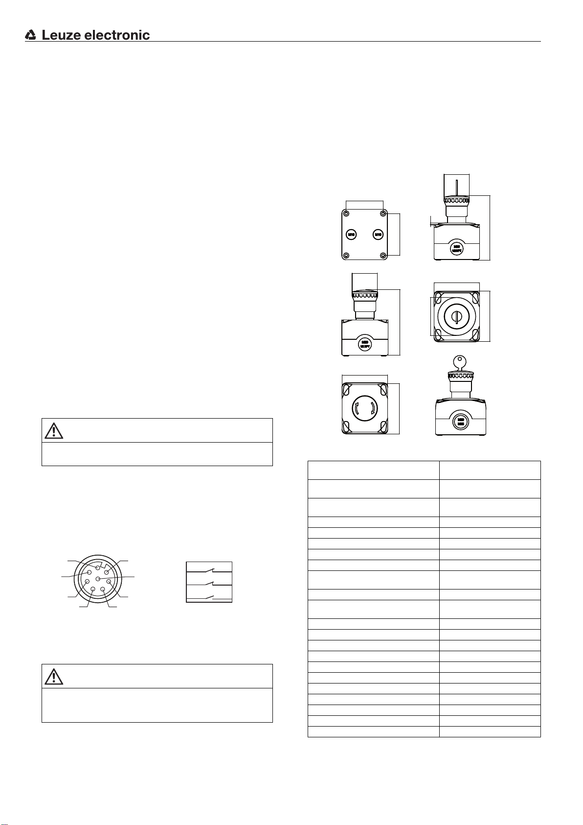
6 Dimensional drawings
Ø
40
58,5
2,8
66,5
Ø
40
72
102,3
Ø60
72
80
101,8
80
WARNING
The system is to be brought to a standstill safely and safeguarded against re-starting before mounting and connection.
Screw the housing base tightly to the force-fit surface.
Break the provided cable bushing free.
Lead through the cable gland with the corresponding sealing
class and screw it in firmly.
Lead the cable in and screw it in firmly with the fixing nut.
Connection = E-Stop command output to 2 x NC, signaling to
NO.
2
3
4
5
1
Pin 3
8
7
Pin 5
Pin 7
1
1
3
2
2
4
6
Place the upper housing on the lower part and screw it on firmly.
Put the caps on.
Observe the technical data.
4 Tests
WARNING
Severe accidents may result if tests are not performed properly.
Make certain that there are no people in the danger zone.
First checks
The ESB2x is force-fit fastened acc. to specifications. Rotation is
therefore not possible.
Switch on the machine.
Press the button.
Pin 4
Pin 6
Pin 8
7 Technical data
Integration in accordance with EN 62061,
IEC 61508
Integration in accordance with
EN ISO 13849-1
Number of switching cycles to dangerous
failure (B10
Service life (T
Temperature range, operation -25°C to +80°C
Dirt level in accordance with EN 60947-1 3
Safety class II
Certifications cULus
Mechanical life time in accordance with
EN ISO 13849-1
Mechanical life time, contact (without load) 20,000,000
Actuation frequency in accordance with
IEC 60947-5-1
Contact allocation 2NC/1NO
Switching principle Creep contact
Contact opening Force-fit
Contact material Silver alloy
“Stop” inscription 60 mm screen
Actuation force, red button 25 N
Mounting Structure
Head / housing color red/yellow-black
Button/housing material PA/PC
Type of fastening passageway fastening
Protection class IP67, IP69K
)
d
) 20 years
M
up to SIL 3
up to PL e, up to cat. 4
600,000
300,000
max. 3600 per hour
Original Instructions ESB200
Buy: www.ValinOnline.com | Phone 844-385-3099 | Email: CustomerService@valin.com
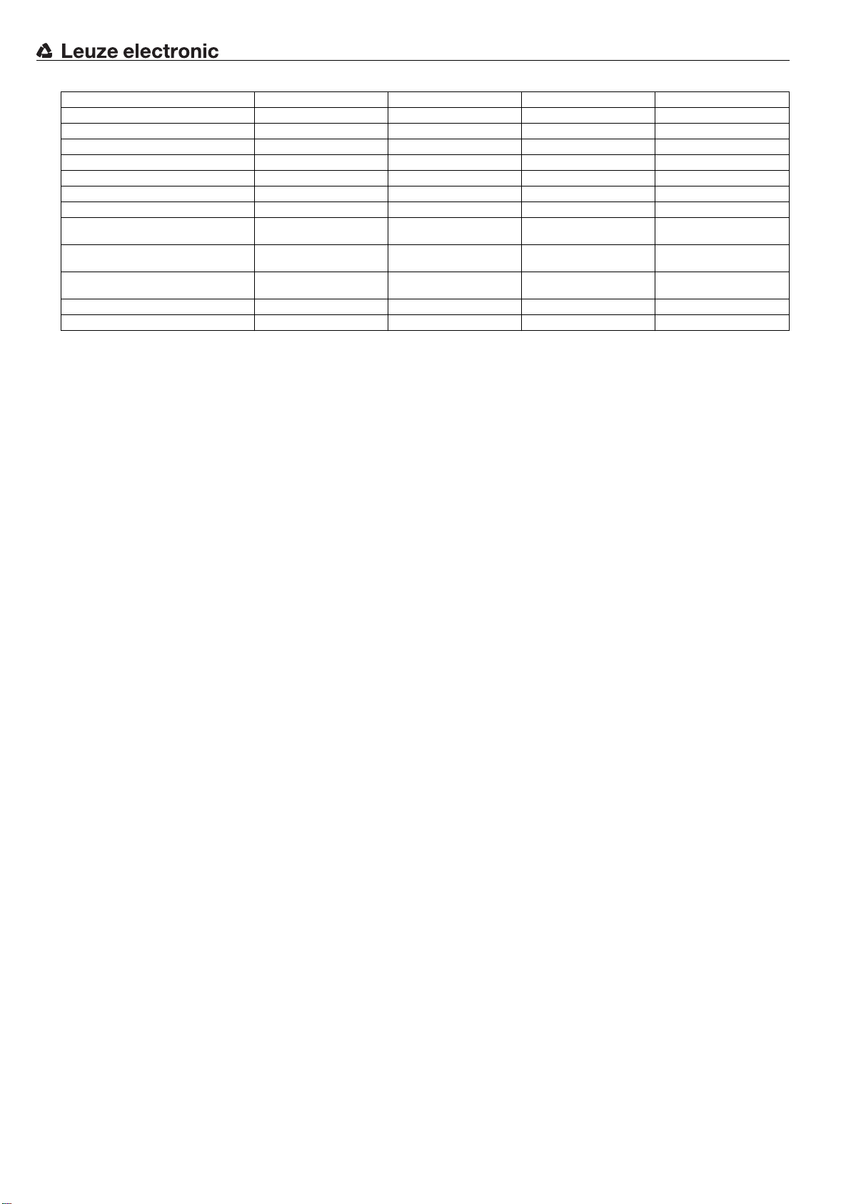
Article ESB200-4TR-C ESB200-4KR-C ESB200-4TR-M12p ESB200-4KR-M12p
Screw terminal tightening torque 0.6 - 0.8 Nm 0.6 - 0.8 Nm N.a. N.a.
Type of unlocking, turning button key button key
Cable entries 3 x M20, 2 x M16 3 x M20, 2 x M16 1x 1x
Connection system Screwterminals Screw terminals M12 plug M12 plug
Permissible wire gauge 0.5 mm
Conventional thermal current 10 A 10 A 2 A 2 A
Rated insulation voltage Ui 600 V AC/DC 600 V AC/DC 30 V AC, 36 V DC 30 V AC, 36 V DC
Usage category in accordance with
EN 60947-5-1, AC15, Ue (V) / Ie (A)
Usage category in accordance with
EN 60947-5-1, DC13, Ue (V) / Ie (A)
Short-circuit protection according to
IEC 60269-1
Weight 240 g 240g 248 g 248 g
Order no. 63000000 63000002 63000004 63000006
2
to 2 x 2.5 mm
24/6, 48/6, 120/6, 250/6,
400/3
24/2.5, 48/1.3, 125/0.6,
250/0.3
500 V, 10 A, type gG 500 V, 10 A, type gG 500 V, 2 A, type gG 500 V, 2 A, type gG
2
0.5 mm2to 2 x 2.5 mm
24/6, 48/6, 120/6, 250/6,
400/3
24/2.5, 48/1.3, 125/0.6,
250/0.3
2
N.a. N.a.
I 24/2 I24/2
I 24/2 I24/2
 Loading...