

Page 1
4...20 mA
0...10
V
15 - 30 V
DC
IP 67
IEC 60947...
IEC 60947...
IPIP 6868
Factory setting for pin 2 multi funct: teach input
DMU418B-…X3/LTV-M12
DMU418B-…X3/LTC-M12
DMU418B ADVANCED ultrasonic sensors with analog output
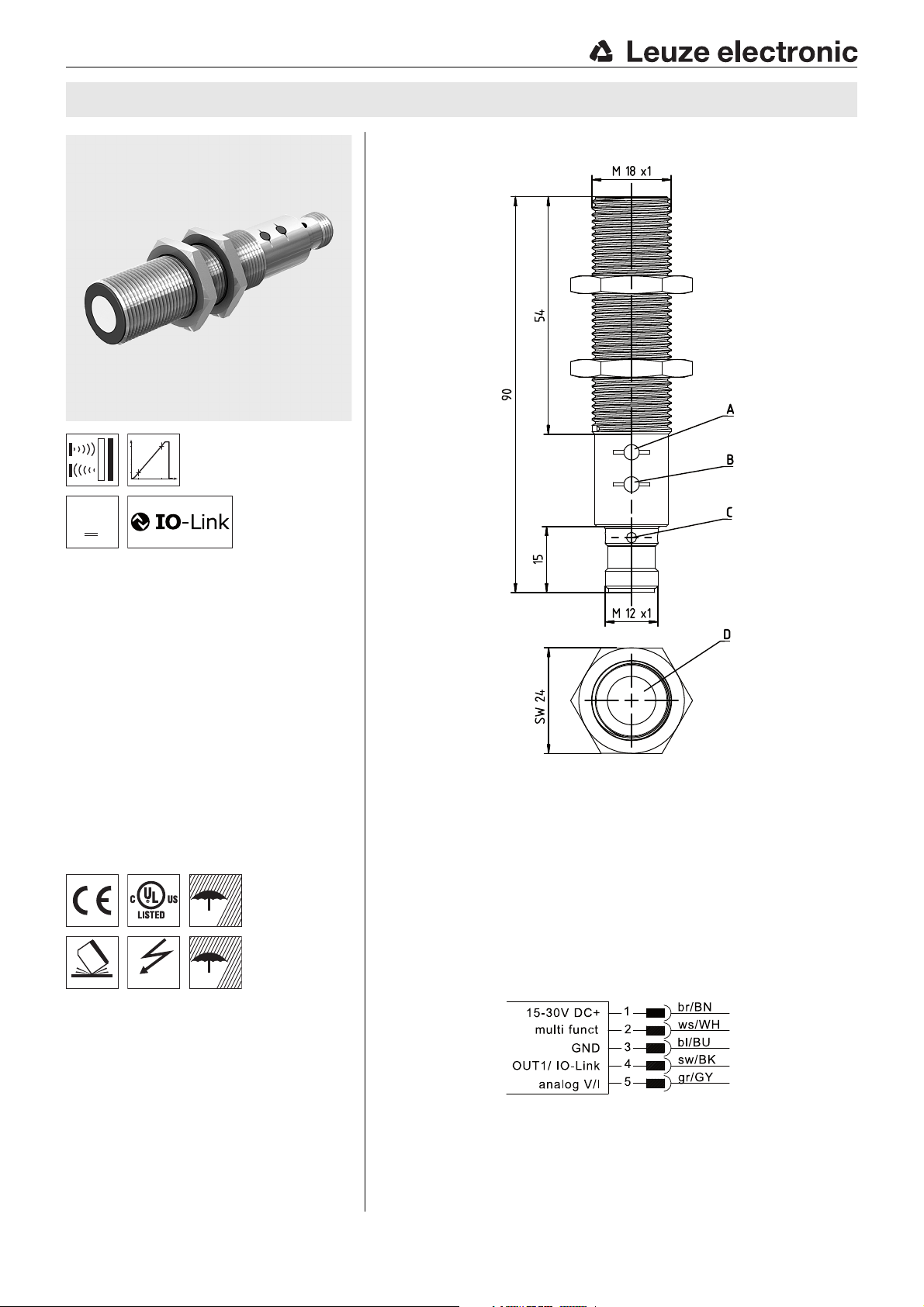
Dimensioned drawing
en 07-2017/02 50124880
25 … 400mm
150 … 1300mm
Function largely independent of surface
properties, ideal for detection of liquids,
bulk materials, transparent media, …
Small dead zone at long scanning range
Temperature-compensated scanning range
and measurement range
1 PNP switching output (NPN) and 1 analog
output 0 … 10V / 4 … 20mA
NEW – Both outputs can easily be taught
using a button
NEW – Stable, all-metal design
NEW – Process data and configuration via
IO-Link interface
NEW – Five operating modes:
scanning, synchronous, multiplex, activation and throughbeam operation
A Control button 2
B Control button 1
C Indicator diodes
D Active sensor surface
Electrical connection
Accessories:
(available separately)
Mounting systems
Mounting adapter M18-M30:
Cables with M12 connector
Teach adapter PA1/XTSX-M12
We reserve the right to make changes • PAL_DMU418BX3LTVC_en_50124880.fm
USB IO-Link master 2.0
Leuze electronic GmbH + Co. KG In der Braike 1 D-73277 Owen
BTX-D18M-D30 (Part no. 50125860)
(K-D …)
(Part no. 50124709)
(Part no. 50121098)
DMU418B-…X3/LT…-M12 - 07
Page 2
Object distance x [mm]
Width y of the sound cone [mm]
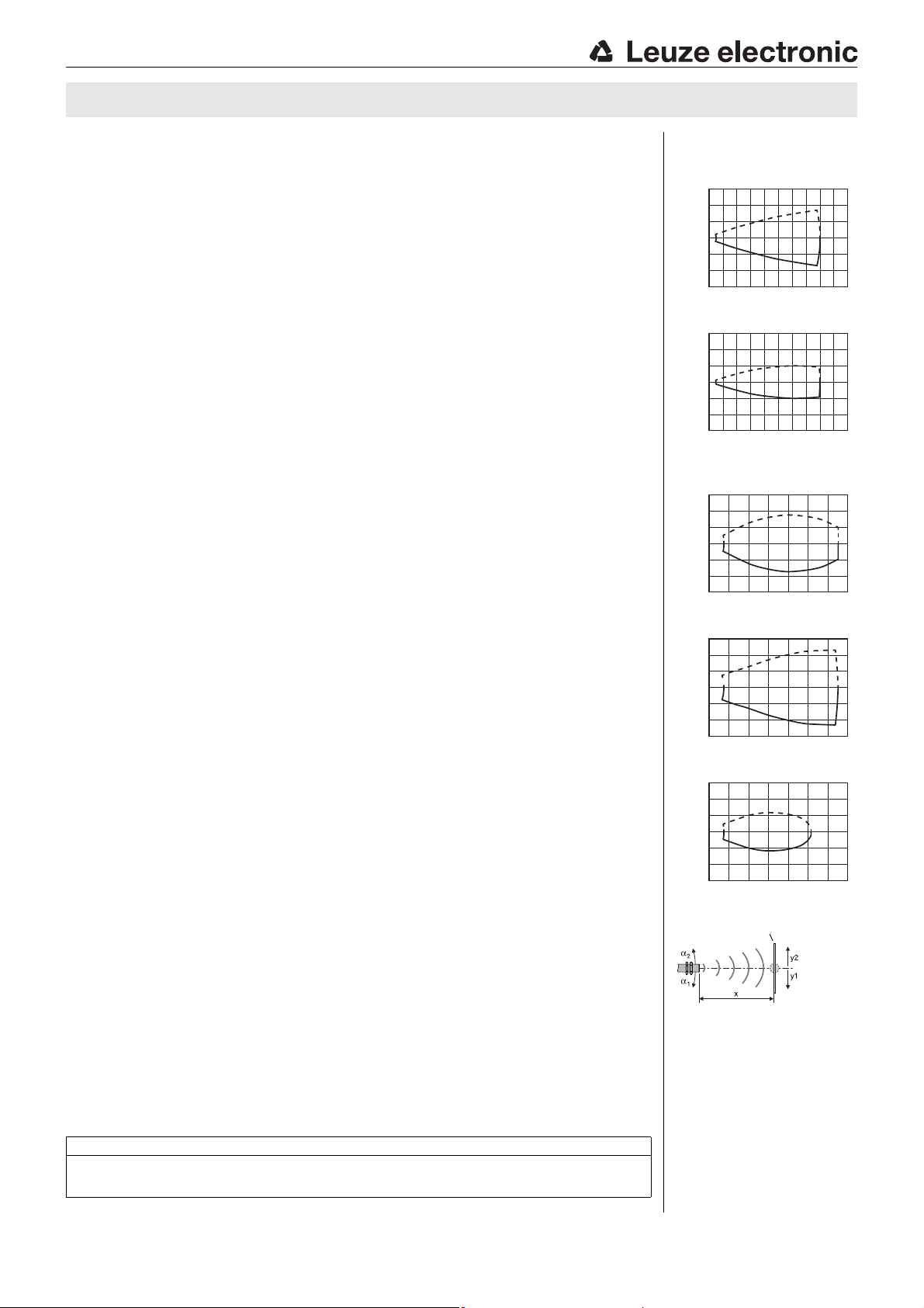
Typ. response behavior (plate 20 x20mm)
-150
-100
-50
0
50
100
150
0 100 200 300 400 500
y1
y2
Object distance x [mm]
Width y of the sound cone [mm]
Typ. response behavior (rod Ø 27 mm)
Object distance x [mm]
Width y of the sound cone [mm]
Typ. response behavior (plate 20 x20mm)
Object distance x [mm]
Width y of the sound cone [mm]
Typ. response behavior (plate 100x 100mm)
Object distance x [mm]
Width y of the sound cone [mm]
Typ. response behavior (rod Ø 27 mm)
Object distance [mm]
Target (fixed):
plate or rod
Sound cone
= f (α,x)
DMU418B
Specifications
Ultrasonic specifications DMU418B-400.X3/… DMU418B-1300.X3/…
Scanning range
Adjustment range 25 … 400mm 150 … 1300mm
Ultrasonic frequency 310kHz 200kHz
Typ. opening angle 9° 16°
Resolution switching output 0.5mm 1mm
Resolution analog output 0.1mm 0.1mm
Direction of beam axial axial
Accuracy (analog output)±0.5% of end value
Reproducibility ± 0.15% of end value
Switching hysteresis (OUT1) 5 mm 10mm
Temperature drift ± 1.5% of end value 1) ± 1.5% of end value 1)
Sensor operating modes
IO-Link COM2 (38.4kBaud)
SIO is supported
Timing
Switching frequency 7Hz 8 Hz
Response time 71ms 62ms
Delay before start-up < 300ms < 300ms
Electrical data
Operating voltage U
Residual ripple ± 10% of U
Open-circuit current ≤ 50mA
Switching output OUT1: 1 x PNP transistor output, IO-Link SIO mode
Function (PNP) NO contact, reversible
Output current SIO mode: max. 150mA per contact,
Switching range adjustment OUT1: control button 1 or teach input
Changeover NO/NC OUT1: control button 1 or teach input
Analog output …X3/LTV
Error signal (analog output) distance too small: approx. 3.8mA,
Indicators
Yellow LED OUT1: object detected
Yellow LED, flashing teach-in / teaching error for 1-point teach /
Green LED object within the scanning range
Green LED flashing IO-Link communication
Yellow and green LEDs flash teach-in/teaching error for window-teach
Mechanical data
Housing all metal - brass, nickel-plated
Weight 50g
Ultrasonic transducer piezoceramic
Connection type M 12 connector, 5-pin
Fitting position any
Environmental data
Ambient temp. (operation/storage) -25°C … +70°C/-30°C … +85°C
Protective circuit
VDE safety class III
Degree of protection IP 67 and IP 68
Standards applied EN 60947-5-2
Certifications UL 508, C22.2 No.14-13
1) At 20°C
2) Target: 20mm x 20mm plate
3) Target: 100mm x 100 mm plate
4) For UL applications: for use in class 2 circuits according to NEC only
5) The ceramic material of the ultrasonic transducer contains lead zirconium titanate (PZT)
6) 1=short-circuit and overload protection, 2=polarity reversal protection, 3=wire break and inductive protection
7) These proximity switches shall be used with UL Listed Cable assemblies rated 30V, 0.5 A min,
in the field installation, or equivalent (categories: CYJV/CYJV7 or PVVA/PVVA7);
Use tool for buttons
8) Ambient temperature 85 °C. Use same voltage supply for all circuits.
1)
4)
B
25 … 400mm
SIO mode: 15 … 30V DC (incl. ± 10% residual ripple),
COM2 mode: 18 … 30V DC (incl. ± 10% residual ripple)
2)
B
150 … 1300mm
1)
± 0.5% of end value 1)
1)
± 0.15% of end value 1)
3)
COM2 mode: max. 100mA per contact
…X3/LTC
voltage output 0 … 10 V, teachable, configurable,
current output 4 … 20mA, teachable, configurable
distance too large: approx. 11V / approx. 21mA
cable short circuit
5)
6)
1, 2, 3
4) 7)8)
Diagrams
DMU418B-400…-M12
150
100
50
0
-50
-100
-150
0 100 200 300 400 500
DMU418B-1300…-M12
300
200
100
0
-100
-200
-300
0 200 400 600 800 1000 1200 1400
300
200
100
0
-100
-200
-300
0 200 400 600 800 1000 1200 1400
300
200
100
0
-100
-200
-300
0 200 400 600 800 1000 1200 1400
y2
y1
y2
y1
y2
y1
y2
y1
Remarks
Operate in accordance with intended use!
This product is not a safety sensor and is not intended as personnel protection.
The product may only be put into operation by competent persons.
Only use the product in accordance with the intended use.
DMU418B-…X3/LT…-M12 - 07 2017/02
Page 3
DMU418B ADVANCED ultrasonic sensors with analog output
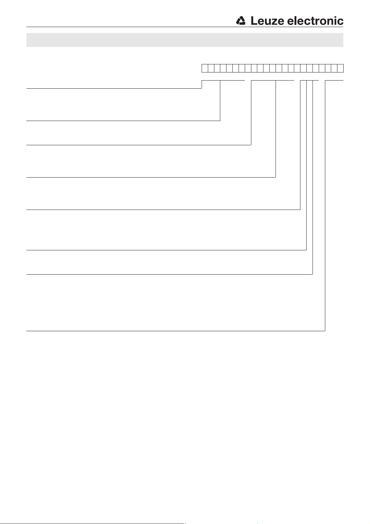
Part number code
DMU418B-1300 .X3/ LTV-M12
Operating principle
HTU Ultrasonic sensor, scanning principle, with background suppression
DMU Ultrasonic sensor, distance measurement
Series
418B 418B Series, cylindrical M18 construction
Scanning range in mm
400 25 … 400
1300 150 … 1300
Equipment (optional)
X "Advanced" design
3 Teach button on the sensor
Pin assignment of connector pin 4 / black cable wire (OUT1)
4 PNP output, NO contact preset
P PNP output, NC contact preset
L IO-Link communication or push-pull (SIO)
Pin assignment of connector pin 2 / white cable wire (Teach-IN)
T Teach input
Pin assignment of connector pin 5 / gray cable wire (OUT2)
4 PNP output, NO contact preset
P PNP output, NC contact preset
V Analog voltage output 0 … 10V
C Analog current output 4 … 20mA
X Connection not assigned (n. c.- not connected)
Connection technology
M12 M12 connector, 5-pin
Order guide
The sensors listed here are preferred types; current information at www.leuze.com.
Designation Part no.
Scanning range / Analog output
25 … 400mm / 0 … 10V DMU418B-400.X3/LTV-M12 50124261
25 … 400mm / 4 … 20mA DMU418B-400.X3/LTC-M12 50124260
150 … 1300mm / 0 … 10V DMU418B-1300.X3/LTV-M12 50124264
150 … 1300mm / 4 … 20mA DMU418B-1300.X3/LTC-M12 50124263
Leuze electronic GmbH + Co. KG In der Braike 1 D-73277 Owen DMU418B-…X3/LT…-M12 - 07
Page 4
Dead zone
Sensor
OUT1 active
yellow LED ON
green LED OFF
OUT1 not active
yellow LED OFF
green LED ON
Distance
Hysteresis
Switching point
Scanning range
OUT1 not active
yellow LED OFF
green LED OFF
OUT1 not active
yellow LED OFF
green LED OFF
Dead zone
Sensor
OUT1 not active
yellow LED OFF
green LED ON
OUT1 active
yellow LED ON
green LED OFF
Distance
Hysteresis
Switching point
Scanning range
OUT1 active
yellow LED ON
green LED OFF
OUT1 active
yellow LED ON
green LED OFF
Dead zone
Sensor
OUT1 active
yellow LED ON
green LED OFF
OUT1 not active
yellow LED OFF
green LED ON
Distance
Hysteresis
Scanning range
OUT1 not active
yellow LED OFF
green LED OFF
OUT1 not active
yellow LED OFF
green LED OFF
Hysteresis
OUT1 not active
yellow LED OFF
green LED ON
Switching point 1 Switching point 2
Dead zone
Sensor
OUT1 active
yellow LED ON
green LED OFF
OUT1 not active
yellow LED OFF
green LED ON
Distance
Hysteresis
Scanning range
OUT1 active
yellow LED ON
green LED OFF
OUT1 active
yellow LED ON
green LED OFF
Hysteresis
Switching point 1 Switching point 2
OUT1 active
yellow LED ON
green LED OFF
DMU418B
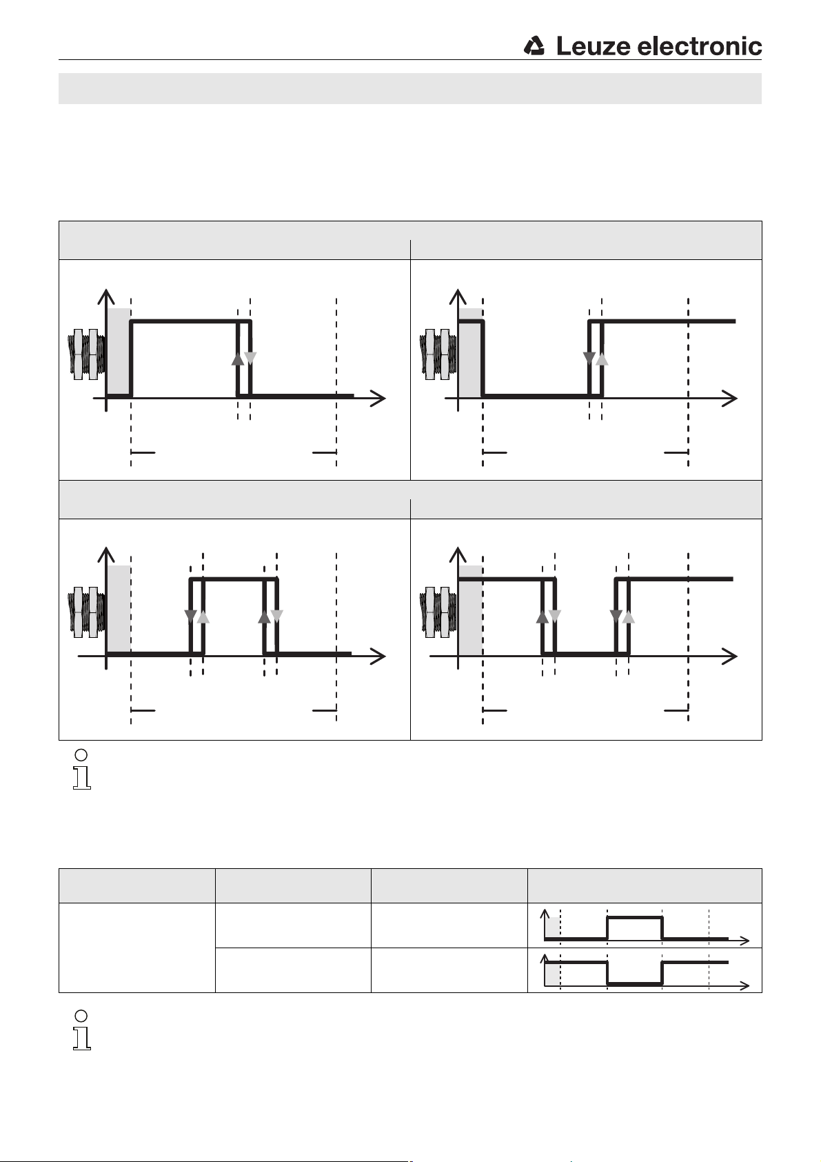
Device functions and indicators – switching output
The sensor has two buttons for adjusting switching output OUT1 and analog output OUT2. Alternatively, all adjustments can also
be made via IO-Link. The multi funct teach input can be used to perform the 1-point teach and the changeover of the switching
function (NO contact/NC contact).
Switching output OUT1
1-point teach (1 switching point)
Switching behavior NO contact Switching behavior NC contact
2-point window-teach (2 switching points)
Switching behavior NO contact Switching behavior NC contact
Notice!
The switching behavior is not defined in the dead zone.
Switching behavior with 2-point window-teach as a function of the switching function
Switching function
configured as
First taught object
distance
Second taught object
distance
Output switching behavior
Far Close
NO contact
NC contact
Close Far
Notice!
In measurement operation, the yellow and green LED only indicate the behavior of output OUT1.
The behavior of output OUT2 is not indicated.
DMU418B-…X3/LT…-M12 - 07 2017/02
Page 5
DMU418B ADVANCED ultrasonic sensors with analog output
Adjustment of the switching points (Teach) using the control buttons
The switching point of the sensor is set to 400mm or 1300 mm (static 1-point teach) on delivery.
By means of a simple operating procedure, the switching point for output OUT1 can be individually taught to an arbitrary distance
within the scanning range with 1-point teach (static) or 2-point window-teach (static).
Moreover, the output function can be switched from NO contact (NO - normally open) to NC contact (NC - normally closed). For
the adjustment, control button 1 is permanently assigned to output OUT1 (see dimensioned drawing).
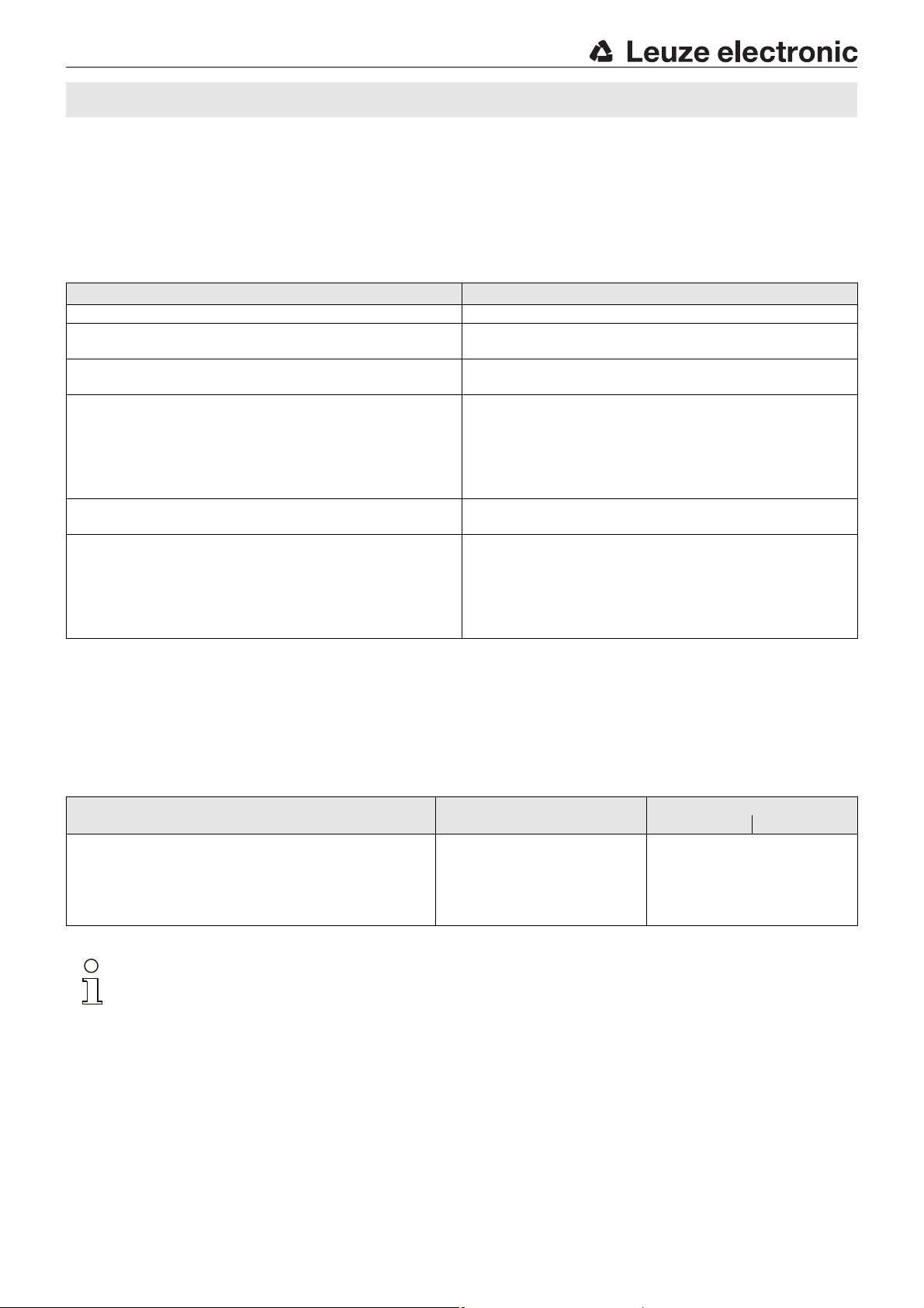
1-point teach (static) 2-point window-teach (static)
1. Place object at desired switching distance. 1. First, place object at desired switching distance for switching point 1.
2. To adjust output OUT1, press button 1 for 2…7s until the yellow LED
flashes at 3Hz.
3. Release the button at the end of the teach event.
The current object distance has been taught as the new switching point.
4. Error-free teach: LED states and switching behavior according to the diagram shown above.
Faulty teach (object may be too close or too far away – please note scanning range):
yellow LED flashes at 5Hz until an error-free teach event is performed.
The affected output is inactive as long as there is a teach error.
1) See table "Switching behavior with 2-point window-teach as a function of the switching function"
2. To adjust output OUT1, press button 1 for 7 … 12 s until the yellow and
green LED flash alternately at 3Hz.
3. Release button. The sensor remains in teach mode and the LEDs con-
tinue to flash.
4. Then, place the object at the desired switching distance for switching
point 2.
Notice:The minimum distance between the switching points is as follows:
5. Briefly press the button again at the end of the teach event.
The switching window has been taught.
6. Error-free teach: LED states and switching behavior according to the diagram shown above.
Faulty teach (object may be too close or too far away – please note scanning range):
green and yellow LED flash at 8Hz until an error-free teach event is performed.
scanning range of 400 mm: 40mm
scanning range of 1300mm: 130mm
1)
Adjustment of the switching function (NO/NC) using the control buttons
Control button 1 can be used to switch the switching function of output OUT1 from NO contact to NC contact (or vice versa).
To do this, proceed as follows:
Action / Description Control button
Changeover of the switching function:
Switching output OUT1 is set as NO contact ex works. If the switching
function is changed, the switching output is changed to the opposite
state (toggled).
Notice!
For 2-point window-teach, the switching behavior is dependent on the selected object distances for switching
points 1 and 2. See previous page!
Leuze electronic GmbH + Co. KG In der Braike 1 D-73277 Owen DMU418B-…X3/LT…-M12 - 07
Press button 1 of the
switching output for longer than 12s.
Both LEDs flash alternately for a short
the output functions as an NO contact.
the output functions as an NC contact.
Indicator diode
GREEN YELLOW
time at 3Hz.
If the yellow LED is then ON,
If the yellow LED is then OFF,
Page 6
Device functions – analog output
Dead zone
Sensor
Error
approx.
11V
approx.
21mA
Start point
0V
4mA
Object distance
Remote error:
Object outside of
the measurement range
Error
approx.
3.8mA
End point
10V
20mA
Measurement range
Close error:
Object outside of
the measurement range
Dead zone
Sensor
Object distance
Error
approx.
11V
approx.
21mA
Error
approx.
3.8mA
Remote error:
Object outside of
the measurement range
Close error:
Object outside of
the measurement range
Start point
10V
20mA
End point
0V
4mA
Measurement range
Analog output OUT2
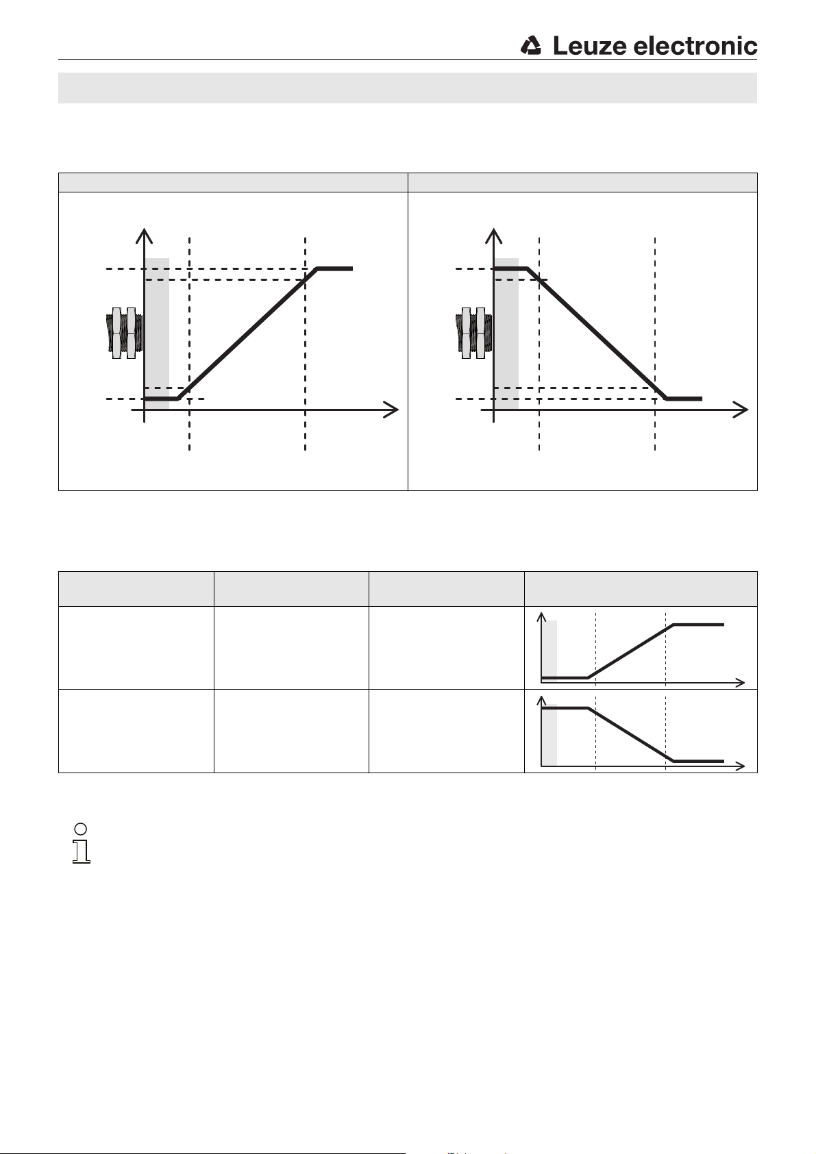
Rising characteristic curve Falling characteristic curve
DMU418B
Characteristic curve behavior as a function of the object distances for start/end of measurement range
Characteristic curve
configured as
Rising characteristic curve Close Far
Falling characteristic curve Far Close
Notice!
In measurement operation, the yellow and green LED only indicate the behavior of output OUT1.
The behavior of output OUT2 is not indicated.
First taught object
distance
Second taught object
distance
Characteristic curve of the analog
output
DMU418B-…X3/LT…-M12 - 07 2017/02
Page 7
DMU418B ADVANCED ultrasonic sensors with analog output
Adjustment of the analog output (Teach) using the control buttons
The choice of distances for start of measurement range and end of measurement range can be used to adjust the characteristic
curve of the analog output.
If an object is located outside of the taught measurement range, an error signal is output. A different analog signal is output here
by the sensor for the errors "distance too close: object outside of the measurement range" and "distance too far: object outside
of the measurement range".
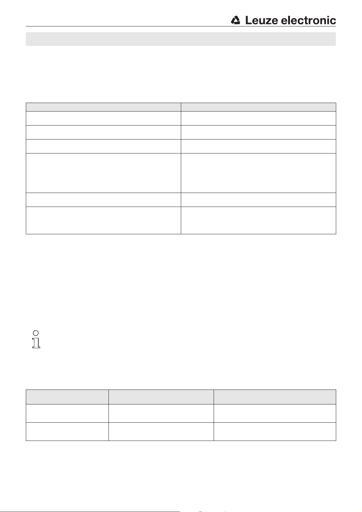
Rising characteristic curve
1. Place object at desired distance for the start point of the measurement
range.
2. To adjust analog output OUT2, press button 2 for 7…12s until the
yellow and green LED flash alternately at 3Hz.
3. Release button. The sensor remains in teach mode and the LEDs con-
tinue to flash.
4. Then, place object at desired distance for the end point of the measure-
ment range.
Notice:The minimum distance between the start and end point of the
5. Briefly press the button again at the end of the teach event.
The characteristic curve with rising curve has been taught.
6. Error-free teach: LED states acc. to table under "Device functions and
indicators".
Faulty teach: green and yellow LEDs flash at 8Hz until an error-free
teach is performed.
1) See table "Characteristic curve behavior as a function of the object distances for start/end of measurement range"
measurement range
is as follows:
scanning range of 400mm: 40mm
scanning range of 1300mm: 130 mm
1)
Falling characteristic curve 1)
1. Place object at desired distance for the end point of the measurement
range.
2. To adjust analog output OUT2, press button 2 for 7…12s until the
yellow and green LED flash alternately at 3Hz.
3. Release button. The sensor remains in teach mode and the LEDs con-
tinue to flash.
4. Then, place object at desired distance for the start point of the measurement range.
Notice:The minimum distance between the start and end point of the
measurement range
is as follows:
scanning range of 400mm: 40 mm
scanning range of 1300mm: 130mm
5. Briefly press the button again at the end of the teach event.
The characteristic curve with falling curve has been taught.
6. Error-free teach: LED states acc. to table under "Device functions and
indicators".
Faulty teach: green and yellow LEDs flash at 8Hz until an error-free
teach is performed.
Adjusting the sensor via the teach input
multi funct connection pin 2 is configured ex works as a teach input. Via the teach input, you can
- lock the control buttons.
- perform a 1-point teach (static) of the switching output.
- perform a 2-point window-teach (static) of the switching output.
- perform a 2-point teach of the characteristic curve of the analog output.
LOW signal level≤ 0.191 • U
Signal level HIGH ≥ 0.809 • U
or not connected
B
B
Locking of the control buttons
Action
Locking the control buttons HIGH signal (permanent)
Unlocking the control buttons LOW signal or not connected (permanent)
Leuze electronic GmbH + Co. KG In der Braike 1 D-73277 Owen DMU418B-…X3/LT…-M12 - 07
Pin 2
(multi funct)
Description
As long as the HIGH signal is continuously applied, the
sensor cannot be adjusted with the control buttons.
The control buttons of the sensor are disabled.
As long as the LOW signal is continuously applied or pin 2
remains unconnected, the sensor can be adjusted with the
control buttons.
Page 8
Teach of switching output and analog output
U
Teach LOW
t
Teach1
t
Teach2
t
U
Teach HIGH
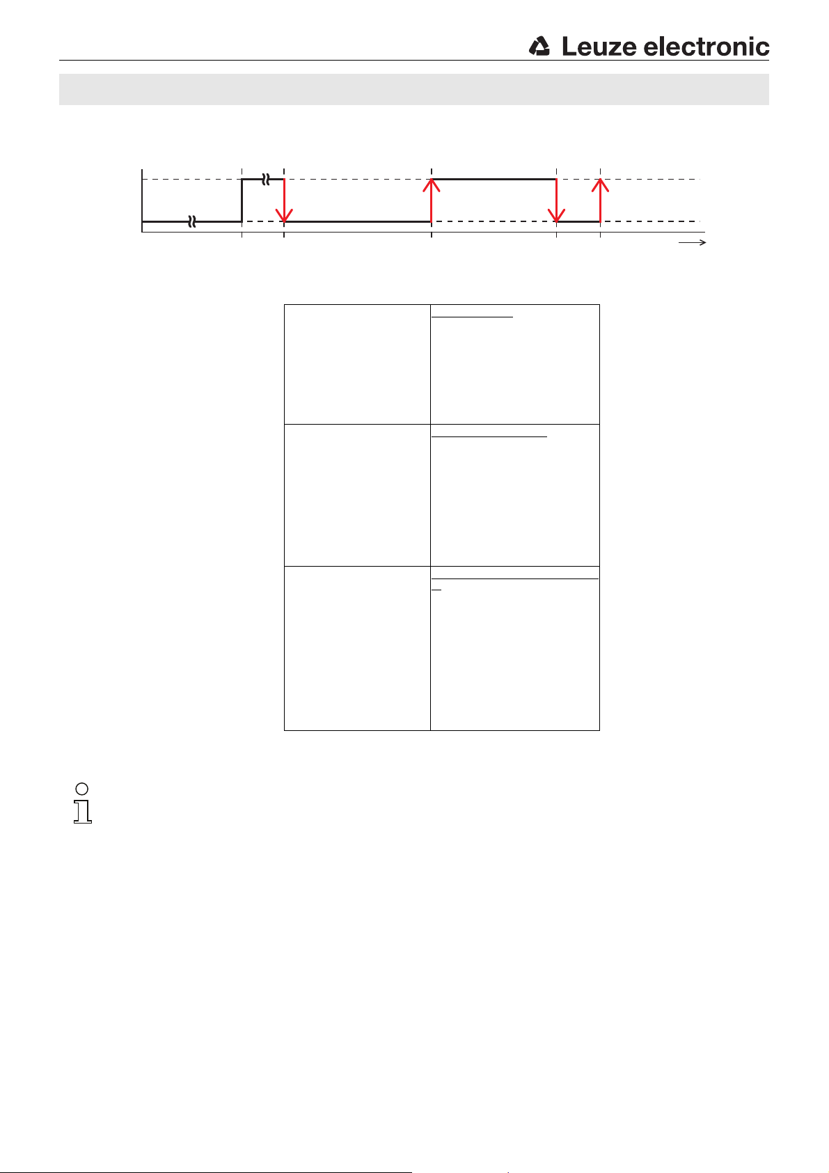
After the delay before
start-up (≤ 300ms) has
elapsed, the control buttons of the sensor can be
operated.
≥ 20ms Pulse duration t
Tea ch1
Pulse duration t
Tea ch2
20 …
ms
≥ 20ms
Switching output OUT1:
t
Tea ch1
= 20 … 80ms
1-point teach (static)
Place object.
The current object distance is taken over as
switching point 1
with the rising edge of t
Teach2
.
Do not change the object distance!
The falling edge of t
Teach2
ends the teach event.
Switching output OUT1:
t
Tea ch1
= 120 … 180ms
2-point window-teach (static)
Place object.
The current object distance is taken over as
switching point 1
with the rising edge of t
Teach2
.
Sensor remains in teach mode.
Change the object distance now!
The current object distance is taken over as
switching point 2 and the teach event is
ended with the falling edge of t
Teach2
.
Analog output OUT2:
t
Tea ch1
= 120 … 180ms
2-point teach of analog characteristic (static)
Place object.
The current object distanc e is taken over as the
start point of the measurement range with the
rising edge of t
Teach2
.
Sensor remains in teach mode.
Change the object distance now!
The current object distanc e is taken over as the
end point of the measurement range
and the teach event is ended with the falling
edge of t
Teach2
.
Switching point 2Switching point 1
Buttons locked
Buttons can be operated
DMU418B
Notice!
The procedure is identical for the 2-point window-teach for switching output OUT1 and for the 2-point teach of
the characteristic curve of analog output OUT2 via the teach input. The characteristic curve and switching window can only be adjusted independently via the control buttons or the IO-Link interface.
The changeover of the switching function (NC contact/NO contact) and the characteristic curve (rising/falling)
is not possible via the teach input.
DMU418B-…X3/LT…-M12 - 07 2017/02
Page 9
DMU418B ADVANCED ultrasonic sensors with analog output
IO-Link interface
The ultrasonic sensor features an IO-Link interface acc. to specification V1.1. and satisfies the Smart Sensor Profile.
As a result, the sensor can easily, quickly and, thus, economically be configured and diagnostic information read out. With a small
amount of effort, the sensor can also be integrated in a control.
Overview of the configuration options via IO-Link
Function block Function Description
Operating mode Standard operation The sensor operates as a scanner with background suppression.
Multiplex operation A max. of 10 sensors – 1 master and 9 slaves – can be wired together in a
Synchronous operation A max. of 10 sensors – 1 master and 9 slaves – can be wired together in a
Activation operation The sensor can be activated through an external signal.
Operation as throughbeam sensor The sensor can either be configured as a scanner or as a throughbeam sensor.
Switching output
OUT1
Analog output
OUT2
Temperature Temperature compensation Adjustment option for internal (sensor works with the integrated temperature
Switching point 1/2 The switching points can be directly entered as distance value in mm.
Switching output (OUT1 and OUT2) Adjustment as PNP or NPN switching output
Switching function Adjustment as NC / NO contact.
Switching behavior in the case of error The switching behavior of output OUT1 of the sensor, for objects which are
2-point behavior If a switching output is to operate with 2 switching points, a choice can be made
Teach switching output OUT1 The switching output OUT1 can be taught via the IO-Link interface.
Teach lock Adjustment for locking of control buttons
Analog start value The distance for the start point of the measurement range can be entered directly
Analog end value The distance for the end point of the measurement range can be entered directly
Direction of the characteristic curve Configuration option for rising or falling characteristic curve.
Value range For devices with voltage output:
Unit Adjustment option to ºC or ºF.
Temperature value Entry temperature value in ºC or ºF (if external temperature compensation is
network. To do this, the sensors must be electrically connected with one line. The
master generates a timing signal and all networked sensors are activated with
time-delay.
network. To do this, the sensors must be electrically connected with one line. The
master generates a timing signal and all networked sensors are activated
simultaneously.
Operation as a throughbeam sensor requires 2 sensors, which are electrically
connected through one line.
located outside of the scanning range, can be adjusted.
between 2-point window-teach (factory setting) or 2-point teach (e.g. for simple
pump controls with minimum and maximum fill levels).
in mm.
in mm.
0 … 10V (factory setting); 0 … 5V; 1 … 6 V.
For devices with current output:
4 … 20mA (factory setting); 0 … 20mA.
sensor) or external (with a constant application temperature, this can be
manually entered. The sensor then compensates the measured values at a fixed
rate with this temperature).
desired).
In addition to the configuration functions, a range of sensor information, such as sensor status, sensor diagnostics as well as the
process data, can be called up.
Further information and the device-specific description of the IO-Link interface (IODD) can be found on the Internet at
www.leuze.com
Leuze electronic GmbH + Co. KG In der Braike 1 D-73277 Owen DMU418B-…X3/LT…-M12 - 07
in the Downloads area of the respective sensor.
Page 10

DMU418B
DMU418B-…X3/LT…-M12 - 07 2017/02
 Loading...