

Page 1
4...20 mA
0...10
V
15 - 30 V
DC
IP 67
IEC 60947...
IEC 60947...
IPIP 6868
HTU418B-…
DMU418B-…
HTU430B-3000...
DMU430B-3000...
HTU430B-6000...
DMU418B-…X3/LTV-M12
DMU418B-…X3/LTC-M12
DMU430B-…X3/LTV-M12
DMU430B-…X3/LTC-M12
Factory setting for pin 2 multi funct: teach input
HTU418B-…X3/LT4-M12
HTU430B-…X3/LT4-M12
DMU/HTU 418B/430B Ultrasonic sensors ADVANCED with IO-Link
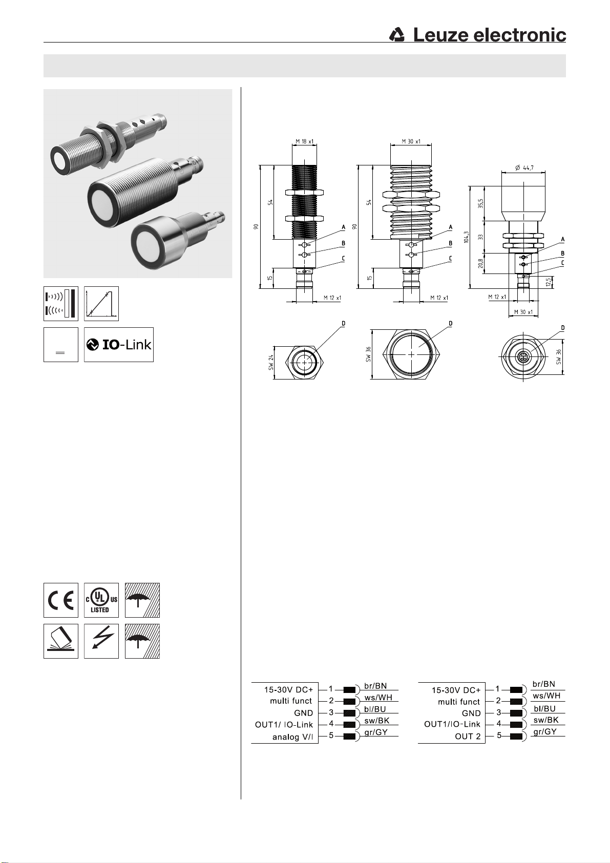
Dimensioned drawing
en 05-2019/05/08 50122144
25 … 400mm
100 … 700mm
150 … 1000 mm
150 … 1300 mm
300 … 3000 mm
600 ... 6000mm
Function largely independent of surface
properties, ideal for detection of liquids, bulk
materials, transparent media, …
Small dead zone at long range
Temperature-compensated range and mea-
surement range
1 PNP switching output (NPN) and 1 analog
output 0 … 10V / 4 … 20 mA
OR
2 independent PNP switching outputs
NEW – Both outputs can easily be taught
using a button
NEW – Stable all-metal design
NEW – Process data and configuration via
IO-Link interface
NEW – Five operating modes:
scanning, synchronous, multiplex, activation and throughbeam operation
Accessories:
(available separately)
Mounting systems
Mounting adapter M18-M30:
BTX-D18M-D30 (Part no. 50125860)
Cables with M12 connector
(K-D …)
Teach adapter PA1/XTSX-M12
(Part no. 50124709), only for HTU
We reserve the right to make changes • DS_U418B_U430B_IOLINK_en_50122144.fm
Advanced
USB IO-Link master 2.0
(Part no. 50121098)
A Control button 2
B Control button 1
C Indicator diodes
D Active sensor surface
Electrical connection
U418B/U430B IO-Link- 05
Page 2
DMU/HTU 418B/430B
About this document
NOTE
This document supplements the device-specific data sheets for the ADVANCED sensors of the
DMU418B, DMU430B, HTU418B and HTU430B series with information and details on the IO-Link
interface.
IO-Link interface
All sensors of the ADVANCED line have an IO-Link interface in accordance with specification 1.1
(October 2011). Devices can be simply, quickly and thus inexpensively configured via this interface.
Furthermore, the sensor transmits its process data and makes diagnostic information available
through it.
Device-specific IODD
At www.leuze.com in the download area for ultrasonic sensors you will find the IODD zip file with all
data required for the installation. Please unpack the zip file in any random directory on your hard drive.
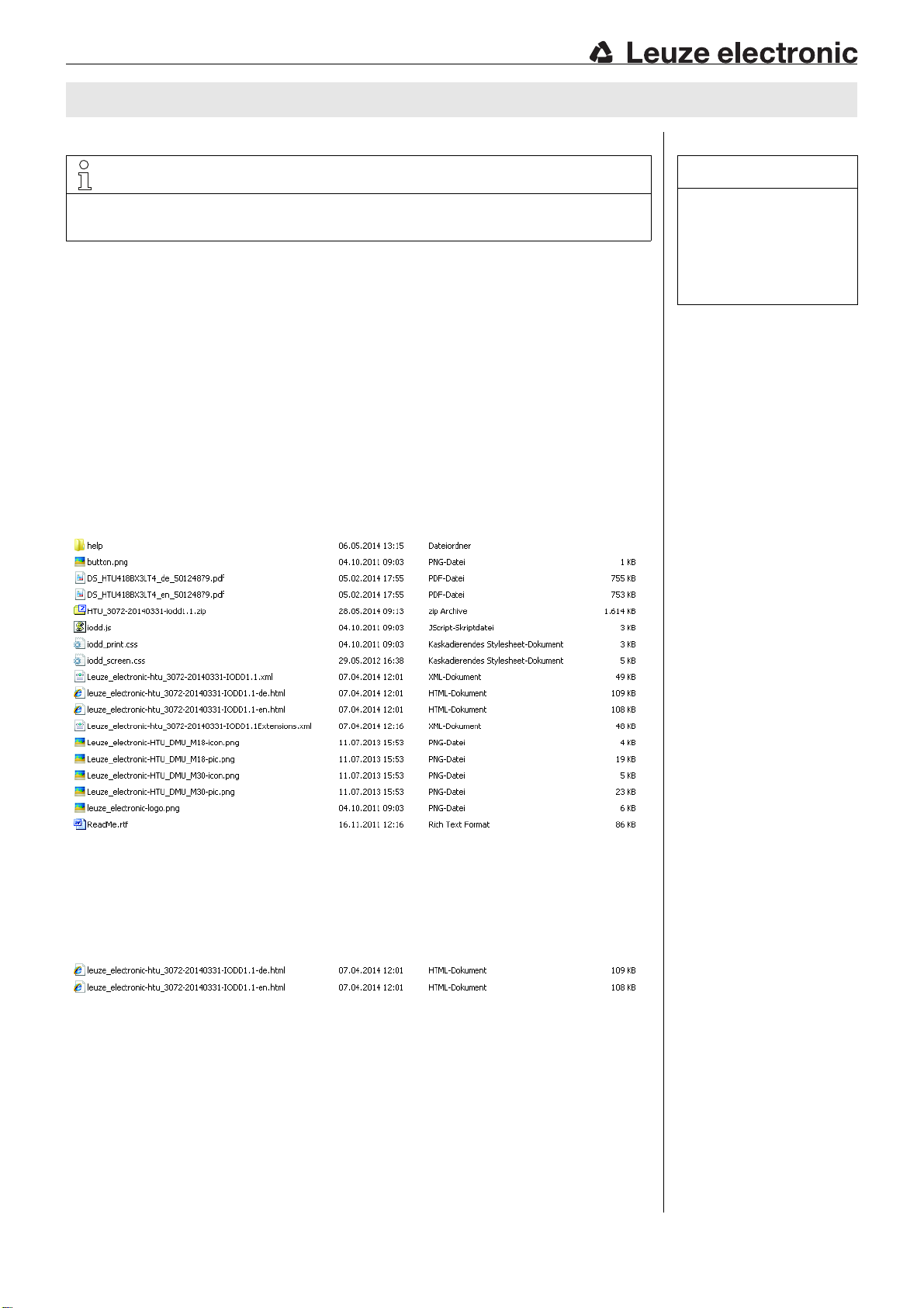
In this directory you should find, for example, for a HTU418B the following files (the same is true for a
HTU430B/DMU418B/DMU430B, but with respectively adapted file names):
Notes
Observe intended use!
This product is not a safety
sensor and is not intended
as personnel protection.
The product may only be put
into operation by competent
persons.
Only use the product in
accordance with its intended
use.
IO-Link parameter documentation
In order to get the complete description of the IO-Link parameters, double-click on one of the two following HTML files (…-de.html: German; …-en.html: English):
U418B/U430B IO-Link- 05 2019/05
Page 3
DMU/HTU 418B/430B Ultrasonic sensors ADVANCED with IO-Link
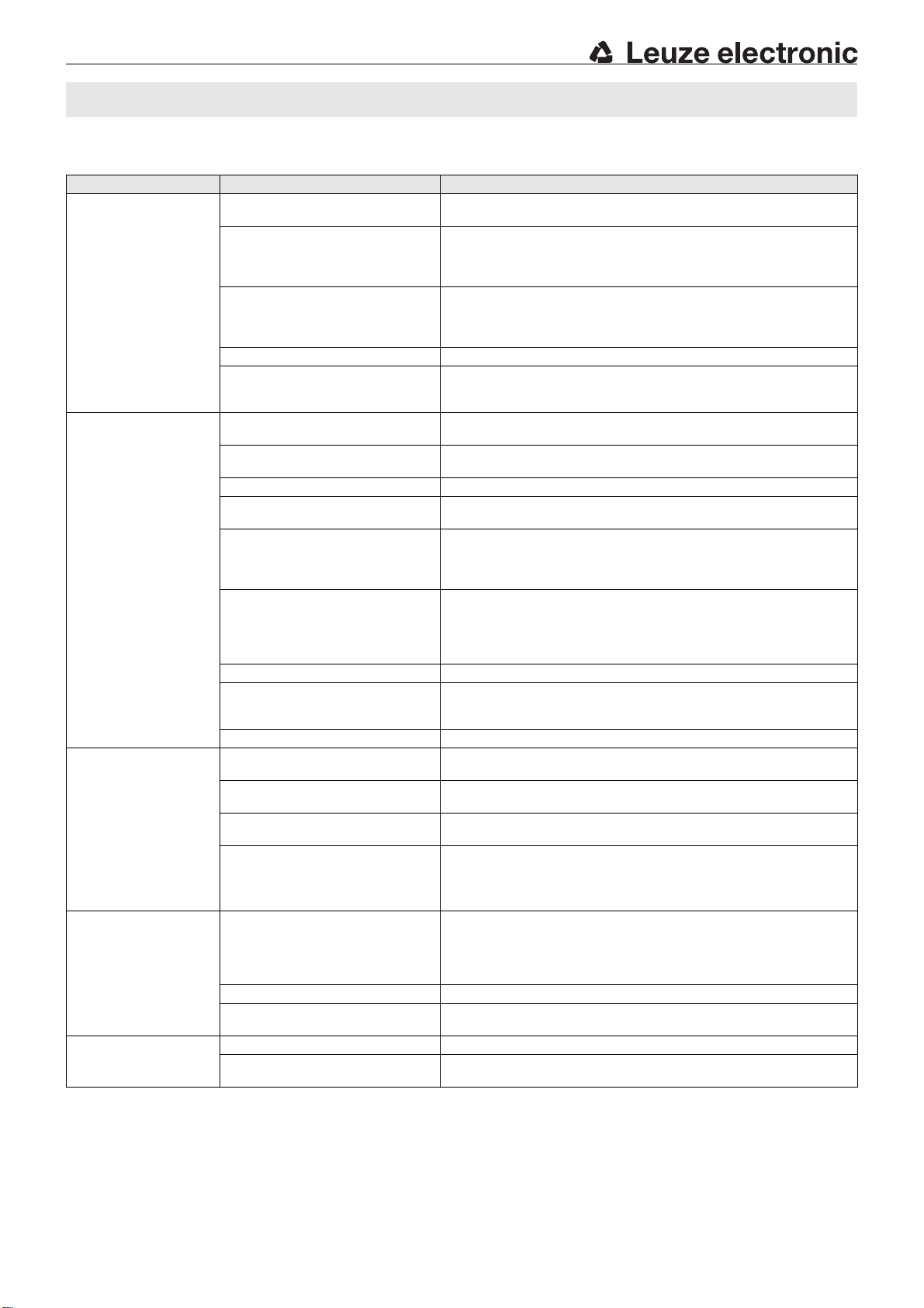
Functions which are configurable via the IO-Link interface
Function block Function Description
Operating mode Standard operation The sensor operates as a diffuse sensor with background
Multiplex operation A max. of 10 sensors – 1 master and 9 slaves – can be wired
Synchronous operation A max. of 10 sensors – 1 master and 9 slaves – can be wired
Activation operation The sensor can be activated through an external signal.
Operation as throughbeam sensor The sensor can either be configured as a scanner or as a
Switching outputs
OUT1 / OUT2
Analog output
OUT2
Temperature Temperature compensation Adjustment option for internal (sensor works with the integrated
Diagnosis LED behavior Adjustment option for the LED behavior in IO-Link operation
1) NO contact: normal switching behavior (not inverted switching);
NC contact: inverted switching behavior (inverted switching).
Switching point 1/2 The switching points can be directly entered as distance value in
Switching output (OUT1 and
OUT2)
Switching function Adjustment as NC / NO contact.
Switching behavior in the case of
error
2-point behavior If a switching output is to operate with 2 switching points, a choice
Delay times The time module can be used to configure a switch-on or switch-off
Teach switching output OUT1 The switching output OUT1 can be taught via the IO-Link interface.
Teach offset An additional or shorter distance at the switching point can be
Teach lock Adjustment for locking of control buttons.
Analog start value The distance for the start point of the measurement range can be
Analog end value The distance for the end point of the measurement range can be
Direction of the characteristic
curve
Output range For devices with voltage output:
Unit Adjustment option to ºC or ºF.
Temperature value Entry temperature value in ºC or ºF (if external temperature
Signal strength Adjustment option for displaying the signal strength via the yellow
suppression.
together in a network. To do this, the sensors must be electrically
connected with one line. The master generates a timing signal and
all networked sensors are activated with time-delay.
together in a network. To do this, the sensors must be electrically
connected with one line. The master generates a timing signal and
all networked sensors are activated simultaneously.
throughbeam sensor. Operation as a throughbeam sensor requires
2 sensors, which are electrically connected through one line.
mm.
Adjustment as PNP or NPN switching output.
1)
The switching behavior of output OUT1 of the sensor, for objects
which are located outside of the operating range, can be adjusted.
can be made between 2-point window-teach (factory setting) or 2point teach (e.g. for simple pump controls with minimum and
maximum fill levels).
delay at the output. This delay time is dependent on the update
interval of the respective device and is calculated using the
following formula:
Delay [ms] = Update interval [ms] * Switch-on/-off delay
entered directly as a distance value in mm. This parameter applies
only for 1-point teach.
entered directly in mm.
entered directly in mm.
Configuration option for rising or falling characteristic curve.
0 … 10V (factory setting); 0 … 5V; 1 … 6V.
For devices with current output:
4 … 20mA (factory setting); 0 … 20mA.
temperature sensor) or external (with a constant application
temperature, this can be manually entered. The sensor then
compensates the measured values at a fixed rate with this
temperature).
compensation is desired).
LED for OUT1.
U418B/U430B IO-Link- 05
Page 4
MasterSlave 1Slave n
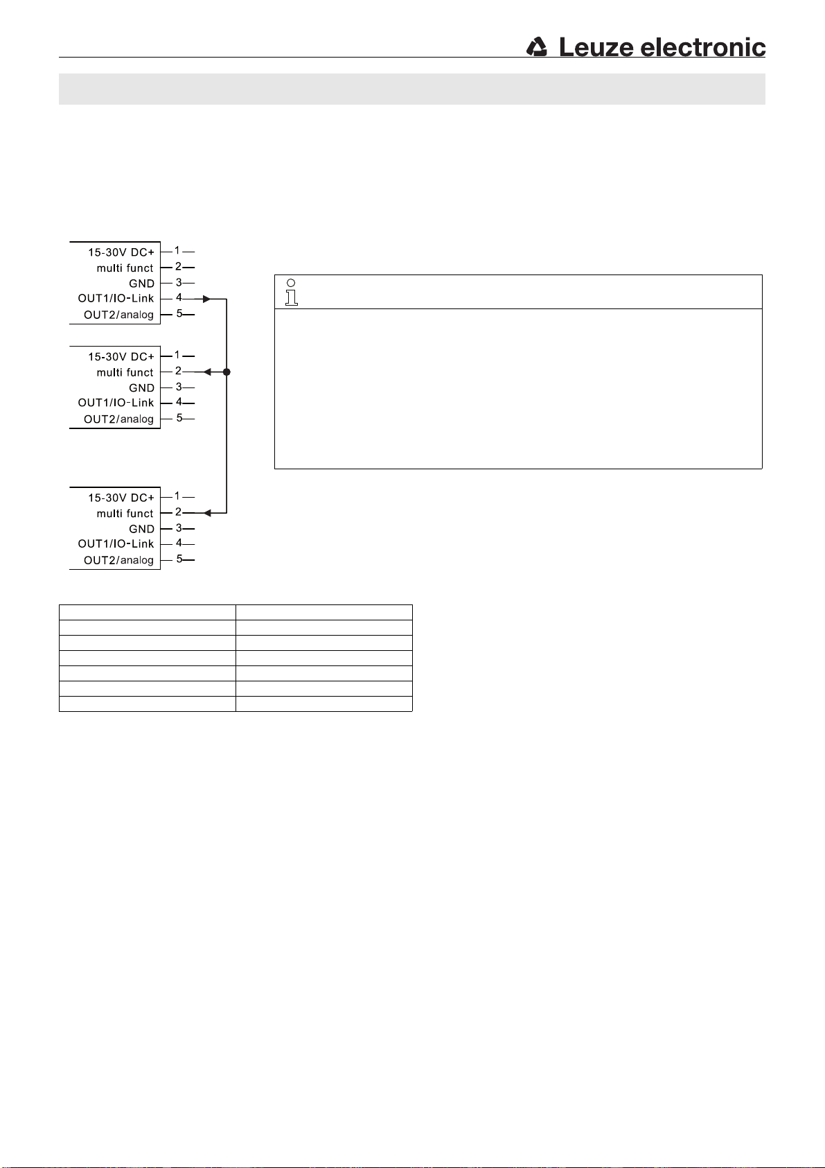
Sensor addressing is set via IO-Link parameter Multiplex Mode Address.
The following applies:
Slave: Number 1 … 9; slave address n = 0 … 8
Master: Master address > slave address, i.e. 1 … 9
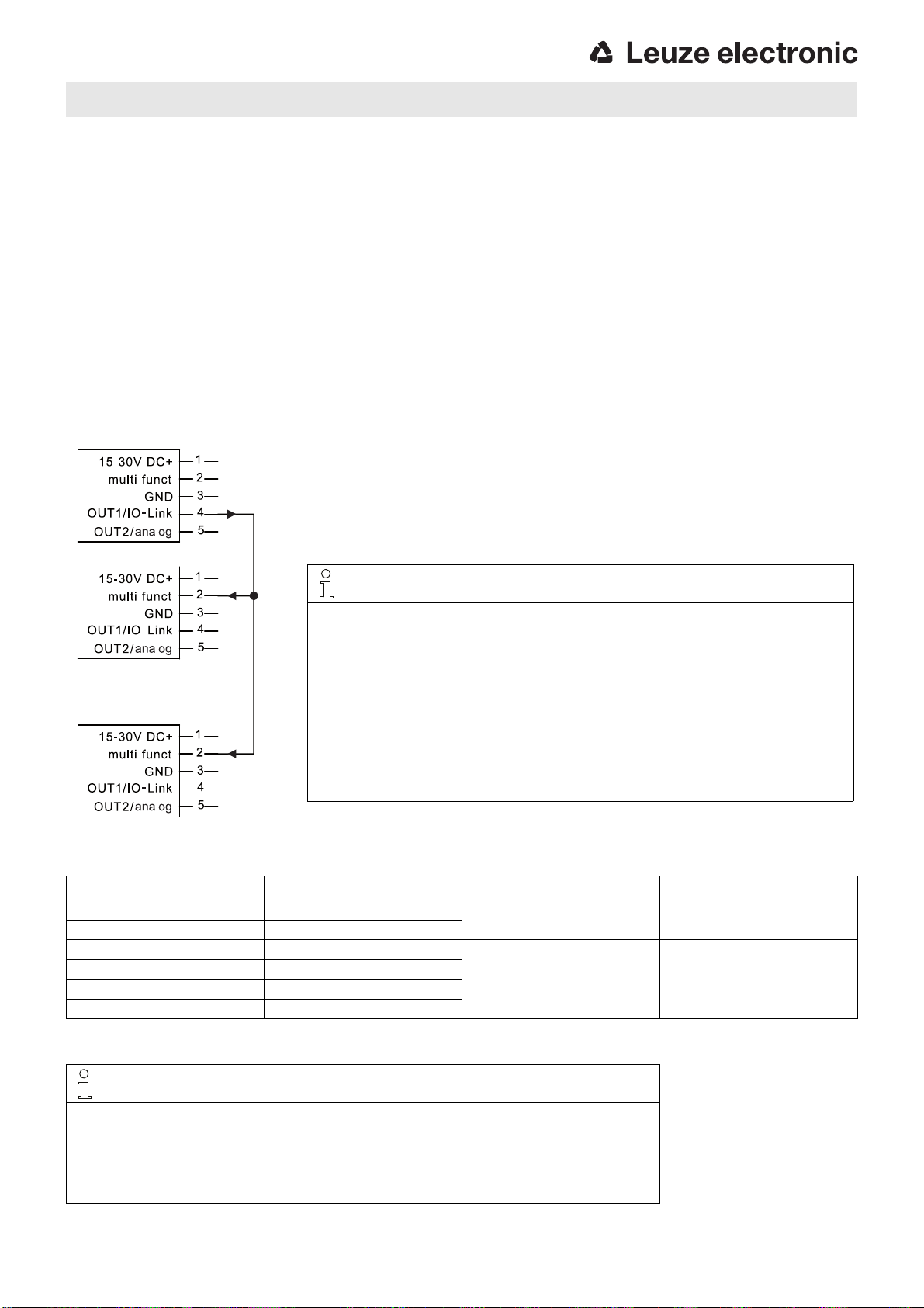
NOTE
Please make certain that the wiring is performed according to the connection diagram.
The sensor with the highest address in network is the master and is connected to pin 4. All
slaves are connected in parallel to pin 2.
Because of the wiring, switching output 1 is generally no longer available to the master!
In case of a HTU418B/HTU430B master, the switching output 2 operates according to stan-
dard operation.
The LEDs on the device show the state of output 2.
In case of a DMU418B/DMU430B master, the analog output operates according to standard
operation.
The green LED indicates whether an object is located within the operating range.
The yellow LED has no function.
DMU/HTU 418B/430B
Operating modes
Standard operation
In the standard mode (= factory standard setting), the sensor operates in the scanning mode with background suppression in accordance
with the description in the product-specific data sheet. The sensor can be configured by means of the control buttons or be taught in this
operating mode via pin 2 multi funct, configured as teach input. Alternatively, configuration of the outputs can also be performed via
IO-Link.
Multiplex operation
In this operating mode the mutual interference of adjacent sensors can be reliably avoided. For this, sensors of the same type are wired
together in a network according to the subsequent diagram.
There must always be 1 master and, depending on the desired size of the network, 1 … 9 slaves. The devices operate in multiplex operation with a cyclically time-delayed transmission pulse and are switched to a passive state outside of the active phase. The response time
of the individual sensors in the network is therefore prolonged in comparison to the response time of a single sensor by the quantity of
networked sensors.
Multiplex operation wiring schematic
Response time in multiplex operation
Operating range Cycle time t
25 … 400mm 12ms
100 … 700mm 13ms
[ms] Max. response time [ms]
cycle
(7*n+2)*t
cycle
1)
Min. response time [ms] 1)
(3*n+2)*t
cycle
150 … 1000mm 18ms
150 … 1300mm 18ms
300 … 3000mm 38ms
600 … 6000mm 76ms
1) n = number of sensors (master + number of slaves)
NOTE
The max. response time results if an object suddenly enters the operating range.
The min. response time results if an object was previously located outside of the operating range and
is then pushed into the operating range.
Example:
A network with 3 sensors (1 master, 2 slaves) and operating range 150 … 1300mm has a total
response time of between (1*3+2)*18ms = 90ms and (3*3+2)*18ms = 198 ms.
U418B/U430B IO-Link- 05 2019/05
(3*n+2)*t
(1*n+2)*t
cycle
cycle
Page 5
MasterSlave 1Slave n
In contrast to multiplex operation, addressing of the sensors is unnecessary.
NOTE
Please make certain that the wiring is performed according to the connection diagram.
The sensor that is connected to pin 4 is the master and generates the synchronisation signal
for all other slave sensors in the network. These are connected in parallel to pin 2.
Because of the wiring, switching output 1 is generally no longer available to the master!
In case of a HTU418B/HTU430B master, the switching output 2 operates according to stan-
dard operation.
The LEDs on the device show the state of output 2.
In case of a DMU418B/DMU430B master, the analog output operates according to standard
operation.
The green LED indicates whether an object is located within the operating range.
The yellow LED has no function.
DMU/HTU 418B/430B Ultrasonic sensors ADVANCED with IO-Link
Synchronous operation
In this operating mode the mutual interference of adjacent sensors can be avoided. For this, sensors of the same type are wired together
in a network according to the subsequent diagram.
There must always be 1 master and, depending on the desired size of the network, 1 … 9 slaves. The devices work in synchronous operation with a simultaneous transmission pulse.
Synchronous operation wiring schematic
Response time in synchronous operation
Operating range Typ. response time
25 … 400mm 24ms
100 … 700mm 26ms
150 … 1000mm 18ms
150 … 1300mm 18ms
300 … 3000mm 38ms
600 … 6000mm 76ms
U418B/U430B IO-Link- 05
Page 6
MASTER
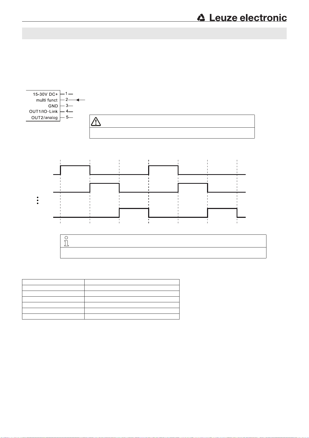
ATTENTION
As long as the activation signal at pin 2 is inactive low (0V),
the state of the outputs remains frozen (last valid state).
Activation signal: active high (UB) = sensor active
inactive low (0 V) = sensor not active
NOTE
With the min. activation time, the sensor operates faster, but also with a low analysis depth. If a high functional reliability is required, we recommend doubling the activation time.
Sensor
activated
Sensor
activated
Sensor
activated
Sensor
activated
Sensor
activated
Sensor
activated
DMU/HTU 418B/430B
Activation operation
In this operating mode, the transmitter of a sensor can be switched on by an external activation signal (UB at pin 2 multi funct). The transmitter is off if the activation signal is passive (0V at pin 2 multi funct).
This operating mode can also be used to avoid the mutual interference of adjacent sensors. The number of activated sensors is thereby
discretionary and the sensors behave as in the standard operation.
Activation operation wiring schematic
Activation signals in activation operation
Sensor 1
Sensor 2
Sensor n
Min. activation time in activation operation
Operating range Minimum length of activation signal
25 … 400mm 38ms
100 … 700mm 41ms
150 … 1000mm 38 ms
150 … 1300mm 38 ms
300 … 3000mm 78 ms
600 … 6000mm 154ms
U418B/U430B IO-Link- 05 2019/05
Page 7
Receiver Transmitter
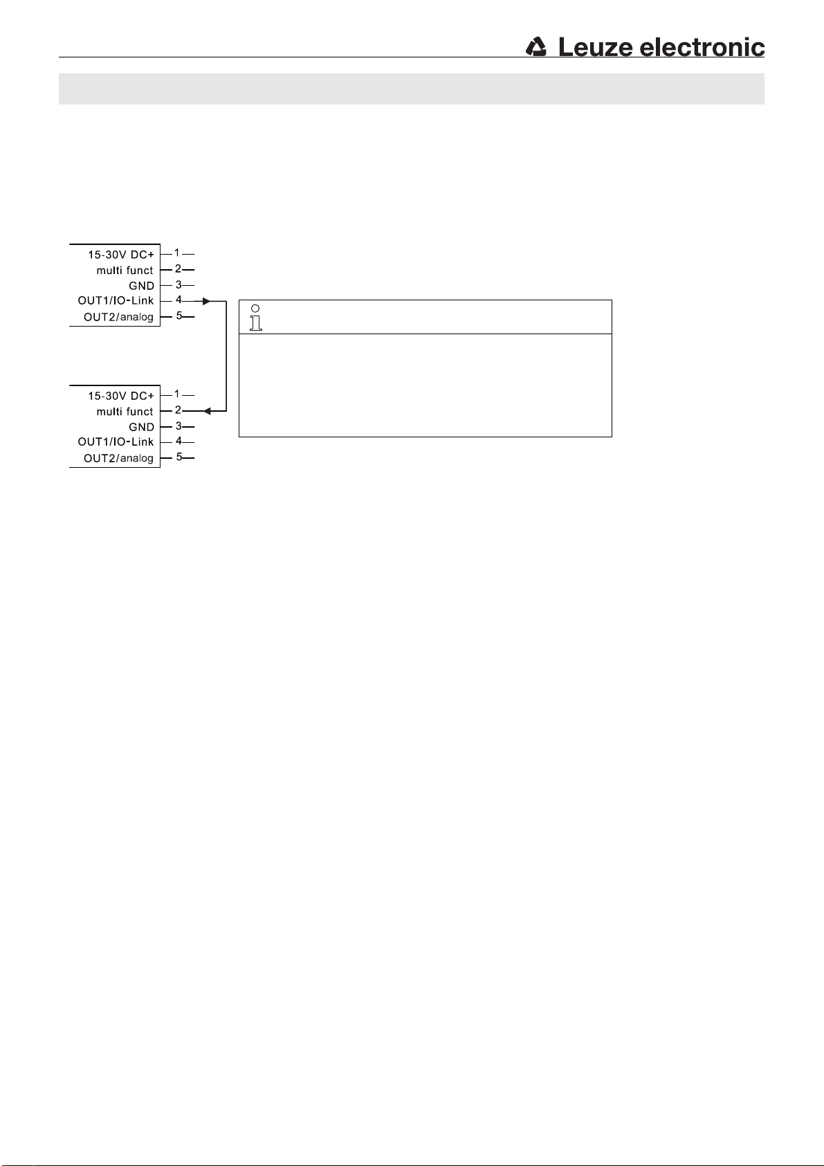
NOTE
Please make certain that the wiring is performed according to the connection diagram. Each sensor can be a transmitter or a receiver. Just
which function is actually performed is determined by the wiring.
In case of a transmitter, the green LED lights up permanently to show
the device's readiness for operation.
The receiver behaves as in standard operation, but the control buttons
are nonfunctional.
DMU/HTU 418B/430B Ultrasonic sensors ADVANCED with IO-Link
Throughbeam operation
In this operating mode, one throughbeam ultrasonic sensor can be put into effect from 2 identical sensors.
Benefits:
Twice the range in comparison to the diffuse reflection mode.
Prevention of the dead zone.
Throughbeam operation wiring schematic
U418B/U430B IO-Link- 05
Page 8
Dead zone
Sensor
OUT active
Yellow LED
ON
Green LED
OFF
OUT not active
Yellow LED
OFF
Green LED
ON
Distance
Hysteresis
Operating range
OUT not active
Yellow LED OFF
Green LED OFF
OUT not active
Yellow LED OFF
Green LED OFF
Hysteresis
OUT not active
Yellow LED
OFF
Green LED
ON
Switching point 1
(IO-Link: SP 2)
Switching point 2
(IO-Link: SP 1)
Dead zone
Sensor
OUT active
Yellow LED
ON
Green LED
OFF
OUT not active
Yellow LED
OFF
Green LED
ON
Distance
Hysteresis
Operating range
OUT active
Yellow LED ON
Green LED OFF
OUT active
Yellow LED ON
Green LED OFF
Hysteresis
Switching point 1
(IO-Link: SP 2)
Switching point 2
(IO-Link: SP 1)
OUT active
Yellow LED
ON
Green LED
OFF
Dead zone
Sensor
OUT active
Yellow LED ON
Green LED
OFF
OUT not active
Yellow LED
OFF
Green LED
ON
Distance
Operating range
OUT not active
Yellow LED OFF
Green LED OFF
OUT not active
Yellow LED OFF
Green LED OFF
Hysteresis
Switching point 1
(IO-Link: SP 2)
Switching point 2
(IO-Link: SP 1)
Dead zone
Sensor
OUT not active
Yellow LED
OFF
Green LED
ON
Distance
Operating range
OUT active
Yellow LED ON
Green LED OFF
OUT active
Yellow LED ON
Green LED OFF
Hysteresis
Switching point 1
(IO-Link: SP 2)
Switching point 2
(IO-Link: SP 1)
OUT active
Yellow LED
ON
Green LED
OFF
DMU/HTU 418B/430B
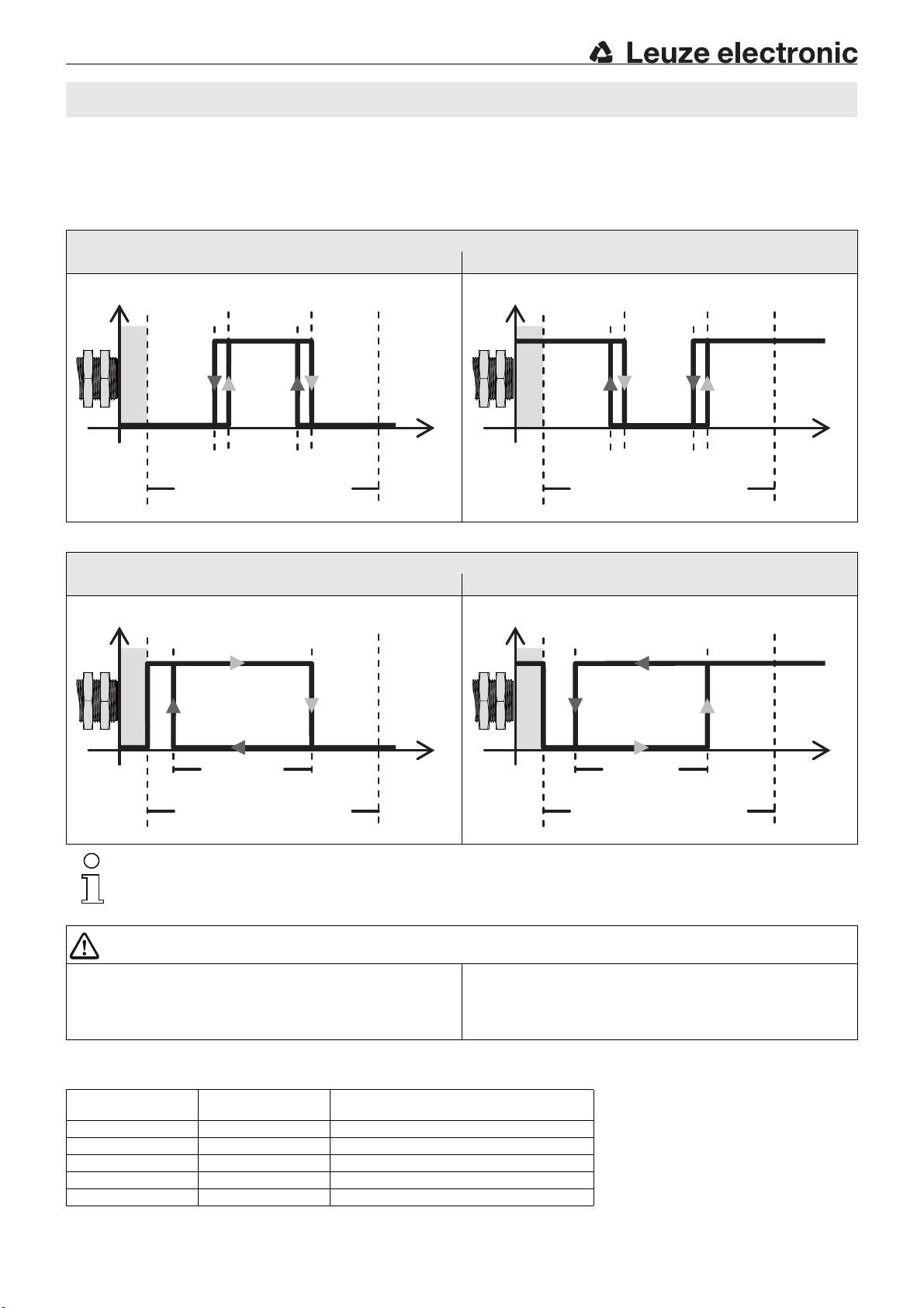
Switching outputs: 2 point behavior
If a switching output is supposed to operate with 2 switching points, a choice can be made between 2-point window-teach (factory setting)
or 2-point-teach (e.g. for simple pump controls with minimum and maximum fill levels). Shown below are the diagrams for the switching
behavior.
Switching behavior in 2-point window-teach
2-point window-teach (2 switching points)
Switching behavior NO contact Switching behavior NC contact
Switching behavior in 2-point teach
2 point teach (2 switching points)
Switching behavior NO contact Switching behavior NC contact
Note!
The switching behavior is not defined in the dead zone.
ATTENTION
Designations in this document
Switching point 1 = close
Switching point 2 = remote
Distance switching point 2 > distance switching point 1
Designations IO-Link
SP 2 = close
SP 1 = remote
Distance SP 1 > distance SP 2
Values to be observed for switching outputs
Detection range Switching hysteresis
25 … 400mm 5mm 50mm
150 … 1000mm 10mm 100mm
150 … 1300mm 10mm 100mm
300 … 3000mm 25mm 250mm
600 … 6000mm 50mm 500mm
U418B/U430B IO-Link- 05 2019/05
Minimum distance between the
switching points (switching output)
Page 9
DMU/HTU 418B/430B Ultrasonic sensors ADVANCED with IO-Link
Analog output - output ranges and minimum distances
Output range
0…20mA 0mA 20.5…21.1mA
4…20mA
3.5 … 3.8mA 20.5 … 21.1mA
1)
0…10V 1) 0 V 10.5 … 11V
0…5V 0V 5.5…6V
1…6V 0…0.5V 6.5…7V
1) Factory setting
Values to be observed for analog outputs
Detection range
Minimum distance between the start and
end point of the measurement range
25 … 400mm 50 mm
150 … 1300mm 100mm
300 … 3000mm 250mm
600 … 6000mm 500mm
Error values
Min. Max.
Diagnosis - signal strength
Adjustment option for displaying the signal strength via the yellow LED for OUT1
If the function is activated, the current signal strength is output relative to the signal of the square standard target as a numerical value via
the IO-Link interface. In addition, the yellow LED for OUT1 flashes at two different flashing frequencies depending on the signal strength.
Current signal strength
Signal strength at the current range [%] =
Signal strength on standard
target
• 100%
Flashing frequency of the yellow LED for OUT1
Signal strength Flashing frequency of yel-
< 20% Constantly OFF
20 … 50% Flashes slowly
50 … 80% Flashes rapidly
> 80% Constantly ON
low LED
Standard targets
Range Size of the standard target
Up to 400mm Plate 20x 20mm
Up to 1300mm Plate 100x100mm
Up to 3000mm Plate 100x100mm
Up to 6000mm Plate 100x100mm
U418B/U430B IO-Link- 05
Page 10
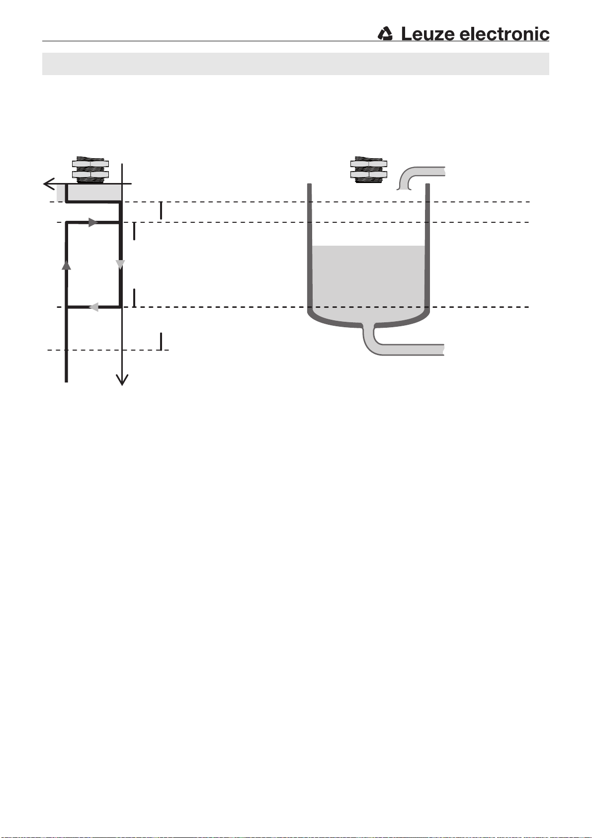
Dead zone
Sensor
OUT not ac-
tive
Yellow LED
OFF
Green LED
ON
Distance
Operating range
OUT active
Yellow LED ONGreen LED
OFF
OUT active
Yellow LED ON
Green LED OFF
Hysteresis
Switching point 1 (IO-Link: SP 2)
Switching point 2 (IO-Link: SP 1)
OUT active
Yellow LED
ON
Green LED
OFF
Sensor
Maximum fill level
Minimum fill level
DMU/HTU 418B/430B
Application notes for container filling level control
The 2-point teach can be utilized for a simple min./max. pump control.
To do this, the sensor is configured as a normally closed (NC) contact and the minimum and maximum fill levels of a container are
assigned as the following:
If the container is empty, e.g. after a cleaning or an initial filling, the sensor must first send an active control signal for a pump which fills
the container up to the maximum fill level.
The control signal now becomes passive and the pump switches off. This is followed by the extraction from the container until the minimum
fill level has been attained. The sensor now sends an active control signal again to the pump, which fills up the container until the maximum
fill level has been attained.
U418B/U430B IO-Link- 05 2019/05
 Loading...