

Page 1
DB 12 B
Double Sheet Testing Unit
en 04-2014/06 50126538
We reserve the right to
make technical changes
TECHNICAL DESCRIPTION
Page 2

© 2014
Leuze electronic GmbH + Co. KG
In der Braike 1
D-73277 Owen / Germany
Phone: +49 7021 573-0
Fax: +49 7021 573-199
http://www.leuze.com
Leuze electronic DB 12 B
Page 3

Table of contents
1 General information ........................................................................................................... 2
1.1 Explanation of symbols ........................................................................................................ 2
1.2 Declaration of conformity ..................................................................................................... 2
2 Safety notices..................................................................................................................... 3
2.1 Safety standards ..................................................................................................................3
2.2 Intended use ........................................................................................................................ 3
2.3 Areas of application ............................................................................................................. 3
2.4 Organisational measures .....................................................................................................3
3 Device overview .................................................................................................................4
4 Specifications..................................................................................................................... 6
5 Mounting the transmitter and receiver............................................................................. 8
6 Electrical connection ......................................................................................................... 9
7 Commissioning ................................................................................................................10
8 Operation - inputs and outputs....................................................................................... 14
9 Diagnosis in the case of error ........................................................................................ 15
10 Application-specific extension types............................................................................. 16
10.1 VDB 12 B/6.10P - Detection of splices on blister material ................................................. 16
10.2 VDB 12 B/6.11N - Automatic teach on first sheet .............................................................. 16
10.3 VDB 12B/6.12P - without teach button in the cover ........................................................... 16
Leuze electronic DB 12 B 1
Page 4
General information
For UL applications:
only for use in "Class 2" circuits according to NEC.
1 General information
1.1 Explanation of symbols
The symbols used in this technical description are explained below.
Attention!
This symbol appears before text passages which must absolutely be observed. Failure to
heed this information can lead to injuries to personnel or damage to the equipment.
Notice!
This symbol indicates text passages containing important information.
1.2 Declaration of conformity
The DB 12 B double sheet testing unit sensor system has been developed and manufactured in adherence with the applicable European standards and directives.
Notice!
The corresponding declaration of conformity can be requested from the manufacturer.
The manufacturer of the product, Leuze electronic GmbH + Co. KG in D-73277 Owen/Teck,
possesses a certified quality assurance system in accordance with ISO 9001.
2 DB 12 B Leuze electronic
Page 5
2 Safety notices
2.1 Safety standards
The DB 12 B double sheet testing unit has been developed subject to the applicable safety
standard EN 60947-5-2 (IEC 60947-5-2).
2.2 Intended use
The DB 12 B double sheet testing unit has been conceived as a monitoring device mainly
for paper working machines. It monitors incoming paper sheets at machines designed to
process single sheets. It is used to detect and signal double sheets in the sheet feeder
during operation.
Attention!
The DB 12 B is not a safety module acc. to EU machine guidelines.
The protection of machine and the device cannot be guaranteed if the device is operated in
a manner not corresponding to its intended use.
Access to or changes on the device, except where expressly described in this manual, are
not authorised.
2.3 Areas of application
Safety notices
Double sheets made of the following materials can be reliably detected by the DB 12 B:
• Paper
• Plastic
• Metal foils
For paper, the measurement range is 20g/m
cardboard).
2
(airmail paper) to 1200g/m2 (homogeneous
2.4 Organisational measures
All entries in this operating manual must be heeded, in particular those in the section "Safety
notices" and "Commissioning".
Keep this technical description in a safe place. It should be accessible at all times.
Safety regulations
Observe the locally applicable safety regulations.
Qualified personnel
Mounting, commissioning and maintenance of the device may only be carried out by qualified personnel.
Leuze electronic DB 12 B 3
TNT 35/7-24V
Page 6
Device overview
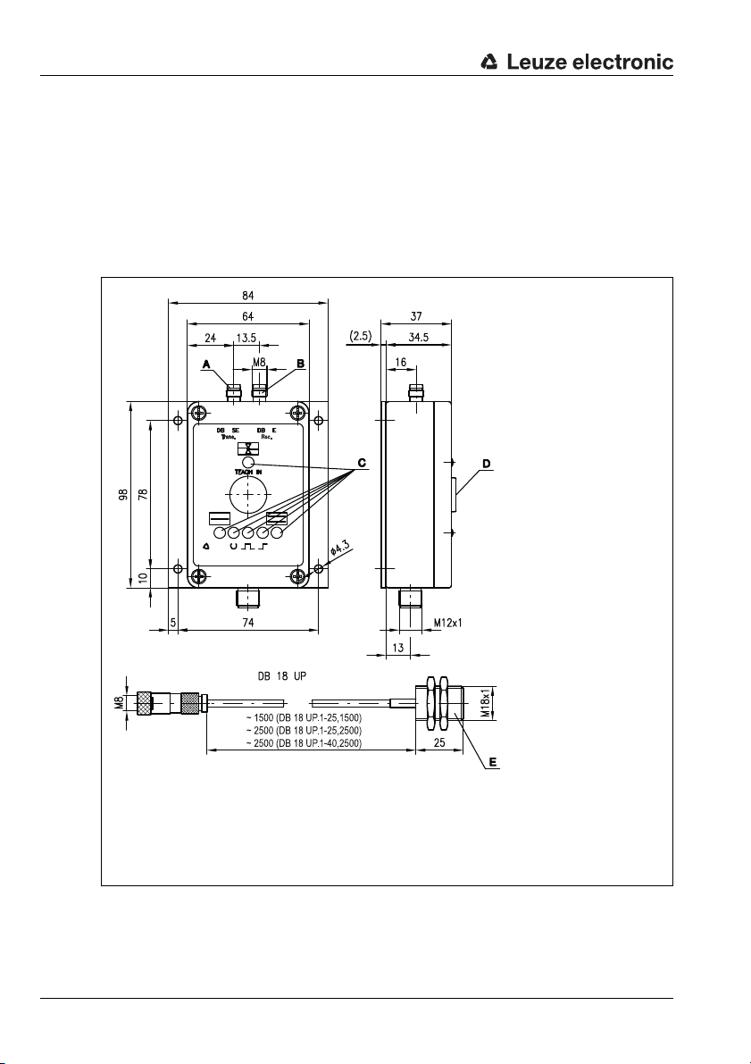
A M8 connector for transmitter DB 18 UP.1. …
B M8 connector for receiver DB 18 UP.1. …
C Indicator diodes
D Push button TEACH IN
E Alternative 42mm housing length (DB 18 UP.1-40, 2500)
3 Device overview
The ultrasonic double sheet testing system consists of a VDB 12 B… analysis amplifier and
a pair of DB 18 UP ultrasonic sensors.
It detects and checks primarily paper, plastic and metal foils which are guided in by feeders.
The device functions as a presence monitor by constantly applying a signal at the single
sheet output when an object is located between the sensors. It functions as a double sheet
testing unit by comparing each sheet with the stored reference value. A detected double
sheet is signalled at the double sheet output.
Figure 3.1: Device overview - dimensions
4 DB 12 B Leuze electronic
Page 7

Controls and indicators
A Green/yellow/red LED TEACH IN
B Ye l l o w L E D SINGLE SHEET
C Red LED DOUBLE SHEET
D Ye l l o w L E D READY
E Ye l l ow L ED TRIGGER IN
F Red LED TRIGGER OUT DOUBLE SHEET
T Push button TEACH IN
VDB 12 B/6.1P
VDB 12 B/6.1N
VDB 12 B/6P
VDB 12 B/6N
Device overview
Figure 3.2: Controls and indicators
Order guide
Designation Model Part No.
Sensor pair M18 x 25 mm, cable length 1.5m DB 18 UP.1-25,1500 501 09014
Sensor pair M18 x 25 mm, cable length 2.5m DB 18 UP.1-25,2500 501 08998
Sensor pair M18 x 42 mm, cable length 2.5m DB 18 UP.1-40,2500 501 08997
Amplifier (positive logic) VDB 12 B/6P 501 04021
Amplifier (negative logic) VDB 12 B/6N 501 04402
Amplifier with TRIGGER input (positive logic) VDB 12 B/6.1P 501 04038
Amplifier with TRIGGER input (negative logic) VDB 12 B/6.1N 501 04403
Accessories
Designation Model Part No.
Cable 5m, PVC, 5-pin, with M12 connectors K-D M12A-5P-5m-PVC 501 04557
Cable 5m, PUR, 8-pin, with M12 connectors K-D M12A-8P-5m-PUR 501 04590
Leuze electronic DB 12 B 5
TNT 35/7-24V
Page 8

Specifications
4 Specifications
Technical data for sensor DB 18 UP
Sensor data
Operating range 20 … 60mm
Converter frequency 200kHz ±2%
Ultrasonic lobe approx. 12°
Mechanical data
Housing nickel-faced brass
Weight 30g
Connection type 1.5/2.5m cable with M8 connector,
Technical data for analysis amplifier VDB 12 B/…
Timing
Switching frequency 200Hz
Input pulse min. 5 ms
Delay before start-up ≤ 300ms
Electrical data
Operating voltage U
Residual ripple ≤ 15% of U
Open-circuit current ≤ 75mA
Switching output …/6… 2 push-pull switching outputs
Function all types
Signal voltage high/low ≥ (UB- 2V) / ≤ 2V
Output current max. 100mA per output
TEACH-/TRIGGER input R
TEACH-/TRIGGER IN active/not active5)…/…P (PNP): ≥ 10V / ≤ 2V or not connected
TRIGGER IN pulse duration ≥ 1ms
TEACH-/TRIGGER IN duration max. 100ms
TEACH IN delay
Indicators
all models:
LED green A double sheet testing unit ready
LED A yellow teach-in process
LED A red flashing error (see chapter 9)
LED yellow B single sheet detected
LED red C double sheet detected
only …/6.1…:
LED yellow D ready for function READY
LED yellow E inquiry signal TRIGGER IN
LED red F double sheet triggered TRIGGER OUT
Mechanical data
Housing aluminium, black powder-coated
Weight 400g
Connection type M12 connector,
6)
3-pin, bending radius r > 25mm
1)
B
…/6.1… 4 push-pull switching outputs 1
all types
only …/6.1…
only …/6.1…
18 … 30VDC (incl. residual ripple)
B
single sheet detected, or ≥ 1 sheet
double sheet detected, or ≥ 2 sheets
double sheet triggered
double sheet testing unit ready to operate
=10kΩ
in
…/…N (NPN): ≤ 2V / ≥ 10V or not connected
approx. 300ms
…/6…:5-pin
…/6.1…:8-pin
2)
3)
4)
6 DB 12 B Leuze electronic
Page 9

Specifications
Environmental data
Ambient temp. (operation/storage) 0 °C … +50°C / -40°C … +70 °C
Protective circuit
VDE safety class III
Protection class IP 65
Standards applied EN 60947-5-2
Certifications UL 508, C22.2 No.14-13
1) For UL applications: only for use in "Class 2" circuits according to NEC.
2) Function: …/…P = active high (+24V); inactive low (0V),
The push-pull switching outputs must not be connected in parallel
3) Is set during low/high transition (…/…P) or high/low transition (…/…N) of the TRIGGER IN
input and reset when the measurement field becomes vacant; trigger delay
response time from edge until switching of the switching output is
4) Is set when the operating voltage is applied if the receiving level is adequate as well as
after the teach event if the calibration was successful.
5) Setting the Teach IN input disables the TEACH IN button (see page 10)
6) Only applies for automatic calibration during sheet movement (automatic teach)
7) 1=transient protection, 2=polarity reversal protection, 3=short circuit protection
8) These proximity switches shall be used with UL Listed Cable assemblies rated 30V,
0.5A min, in the field installation, or equivalent (categories: CYJV/CYJV7 or PVVA/PVVA7)
7)
…/…N = active low (0V); inactive high (+24V).
1,2,3
1) 8)
≤ 1ms
≤ 1ms, i.e.,
Leuze electronic DB 12 B 7
TNT 35/7-24V
Page 10

Mounting the transmitter and receiver
A Receiver
B Angle of inclination
C Sheet material
D Transmitter
Sheet material Recomm. angle of inclination B
0° 15° … 25° 25° … 35°
Standard paper up to 150g/m² X X X
Cardboard X X
Plastics X
A Receiver
B Machine direction
C Sheet material
D Transmitter
5 Mounting the transmitter and receiver
The transmitter and receiver (DB 18 UP) are identical in construction and are to be mounted
according to the table in figure 5.1 at an angle which varies depending on the sheet material.
A larger angle of inclination increases the flutter range; e.g. with a 35° pitch, flutter is permissible within 50% of the measurement field. The distance between transmitter and receiver
must be at least 20mm and can be max. 60mm.
Ensure that alignment is exact (± 1°). If the alignment does not run along the axis, the
working range is reduced.
Notice!
When aligning the transmitter and receiver, take care to ensure the most exact alignment
possible. See "Alignment mode" on page 10. To ensure proper function, the sensors must
be inclined by the angle "B" towards the vertical.
Figure 5.1: Mounting the transmitter and receiver
Figure 5.2: Recommended configuration for maximum functionality
8 DB 12 B Leuze electronic
Page 11

6 Electrical connection
Connect the transmitter and receiver at the appropriate M8 connectors of the VDB 12 B…
analysis amplifier.
Connect the analysis amplifier acc. to connection diagram (figure 6.1).
Figure 6.1: Connection diagrams VDB 12 B…
Circuit logic
VDB 12B/…P -> positive logic
VDB 12B/…N -> negative logic
Electrical connection
Leuze electronic DB 12 B 9
TNT 35/7-24V
Page 12

Commissioning
7 Commissioning
Notice!
If the indicators flash during the initial commissioning, a calibration must first be performed
on a single sheet.
First apply operating voltage. An alignment mode is available for commissioning. This can
be used to check the alignment of the transmitter and receiver.
Alignment mode
Press the TEACH IN button
for > 5s and < 10 s
LEDs and flash synchronously at 3 Hz
LED green:
LED yellow:
LED red: Alignment bad
Notice!
After exiting alignment mode, it is absolutely necessary to perform a calibration.
Calibrating on the material to be detected
For reliable detection of double layers of the medium being processed, it is always necessary to perform a calibration on a single sheet of the medium.
Calibration of the material to be detected can be performed by either pressing the TEACH IN
button on the analysis amplifier for 0.3s to 5s or by means of a control command at the
Teach IN input (pin 5).
Alignment OKExit:
Alignment
critical
press the TEACH IN button < 5s
Align transmitter and receiver until
LED is green.
Only then is it possible to exit alignment mode!
Extraordinary exiting of alignment
mode is possible only by means of
Power OFF!
Align transmitter and receiver until
LED is green.
Only then is it possible to exit alignment mode!
Extraordinary exiting of alignment
mode is possible only by means of
Power OFF!
Notice!
Setting the Teach IN input (pin 5) disables the TEACH IN button. As soon as a signal is applied once via the Teach IN input for the purpose of calibration, the TEACH IN button remains inactive (disabled) until the next Power On.
10 DB 12 B Leuze electronic
Page 13

Commissioning
During the calibration process, LED illuminates yellow.
If the calibration was successful, LED illuminates green and LEDs and yellow.
The single sheet and ready outputs are activated. The reference value remains stored until
the next calibration process.
If the calibration process was not successful, LED flashes red and LEDs and
illuminate red. The double sheet and TRIGGER OUT outputs (double sheet triggered) are
activated.
Notice!
Causes of unsuccessful calibration include e.g.:
• More than 1 sheet between the sensors.
• Unsuitable sheet material, e.g. due to lamination or coating, too thin, too thick, or air
pockets present.
• Pitch to sensors too low.
For devices VDB 12 B/6.1N and VDB 12 B/6.1P with trigger input Trigger IN (pin 6), it is
recommended that the device be configured in such a way that, for Trigger IN, the threshold
signals be adapted so that the amplifier always operates in the optimum range (1., standard
mode). This mode is especially recommended when the material consistency changes
during operation (moisture, density, …).
The VDB 12 B analysis amplifier can be operated in 3 different operating modes (teach
modes):
1. Standard mode:
Teach with intelligent transmitter/receiver control for covering a wide spectrum of
materials. Automatic signal adaptation (averaging) during operation for VDB 12 B/
6.1….
2. Automatic teach:
300ms after sheet detection by the ultrasonic sensors, teach-in occurs automatically.
In this operating mode, manual or external teaching is not necessary. Automatic signal adaptation (averaging) possible during operation for VDB 12 B/6.1…. Another
automatic teach-in is carried out when the ultrasonic path is clear for more than 2s.
3. Fixed switching threshold:
This operating mode is recommended when the process does not permit manual or
external teaching. In this operating mode, the variety of materials to be detected is
limited.
TNT 35/7-24V
Leuze electronic DB 12 B 11
Page 14

Commissioning
Selecting the operating mode (teach mode)
Press the TEACH IN button
for >10s and <15s
1. LED green:
2. LED red:
3. LED off:
Attention!
After selecting the operating mode (teach mode), a calibration must be performed!
LEDs and flash alternately at 3 Hz
Manual teach
(standard mode)
Automatic teach on
the first sheet
Permanently stored
switching threshold
To select and exit:
press the TEACH IN button > 3s
(LED yellow)
To advance to next:
press the TEACH-IN button
<3s
To select and exit:
press the TEACH IN button > 3s
(LED yellow)
To advance to next:
press the TEACH-IN button
<3s
To select and exit:
press the TEACH IN button > 3s
(LED yellow)
To advance to next:
press the TEACH-IN button
<3s
Adapting the averaging calculation (VDB 12 B/6.1… only)
For device variants VDB 12 B/6.1… with trigger input, it is possible to adapt the signals
during running control operation (operating mode 1, standard mode).
Signal adaptation is performed by averaging measurement values which are detected at the
respective Trigger IN. A lower value, e.g. 4, means that an average value is calculated from
4 trigger IN measurement values; a higher value, e.g. 128, means that an average value is
calculated from 128 trigger-in measurement values. Signal adaptation occurs every time the
set number of trigger pulses is reached.
Signal adaptation (averaging) is also possible in operating mode 2, automatic teach.
Attention!
After changing the averaging, recalibration must be performed!
12 DB 12 B Leuze electronic
Page 15

Commissioning
Press the TEACH IN button
for > 15s and < 20s
LED flashes red, LED illuminates yellow.
The other LEDs display the current configured average value
Average value
via
off =
no signal
adaptation
LED LED LED
off off off
4 values
(trigger pulses)
on off off
8 values
(trigger pulses)
off on off
16 values
(trigger pulses,
default)
on on off
32 values
(trigger pulses)
off off on
64 values
(trigger pulses)
on off on
128 values
(trigger pulses)
off on on
No change back on on on
To select and exit:
press the TEACH IN button > 3s
(LED briefly green)
To advance to next:
press the TEACH-IN button < 3s.
To select and exit:
press the TEACH IN button > 3s
(LED briefly green)
To advance to next:
press the TEACH-IN button < 3s.
To select and exit:
press the TEACH IN button > 3s
(LED briefly green)
To advance to next:
press the TEACH-IN button < 3s.
To select and exit:
press the TEACH IN button > 3s
(LED briefly green)
To advance to next:
press the TEACH-IN button < 3s.
To select and exit:
press the TEACH IN button > 3s
(LED briefly green)
To advance to next:
press the TEACH-IN button < 3s.
To select and exit:
press the TEACH IN button > 3s
(LED briefly green)
To advance to next:
press the TEACH-IN button < 3s.
To select and exit:
press the TEACH IN button > 3s
(LED briefly green)
To advance to next:
press the TEACH-IN button < 3s.
To select and exit:
press the TEACH IN button > 3s
(LED briefly green)
TNT 35/7-24V
Attention!
After changing the averaging, recalibration must be performed!
Leuze electronic DB 12 B 13
Page 16

Operation - inputs and outputs
8 Operation - inputs and outputs
The evaluation unit VDB 12 B/6P or VDB 12 B/6N continuously signals the situation occurring between the sensors to two outputs.
The single sheet output (pin 2) is activated as long as one or more sheets are located in
the measurement field.
The double sheet output (pin 4) is activated as long as two or more sheets are located in
the measurement field.
Notice!
For reliable operation, it is essential that calibration be performed on the material to be
detected. See "Calibrating on the material to be detected" on page 10.
Also available on the VDB 12 B/6.1… evaluation units are a Trigger IN query input, a
Trigger OUT double sheet output stored at the query time, as well as a ready output.
If a double sheet is detected on the ascending edge (VDB 12 B/6.1P) or on the falling edge
(VDB 12 B/6.1N) of the query, the Trigger OUT output is set. This remains set until the ultrasonic path is cleared.
The ready output is set if the receiving level is sufficient when operating voltage is supplied.
It remains set until the next calibration, provided a calibration has already been successfully
completed.
The reference value remains stored even after a voltage interruption.
14 DB 12 B Leuze electronic
Page 17

9 Diagnosis in the case of error
Attention!
In the event of an error, the ready output is not active and LED is switched off!
The device LEDs indicate the following error states:
LEDLEDLEDLEDLED Meaning Cause Remedy
red
red
red
red
red
yellow
flashing
(6Hz)
rapid
yellow
flashing
red red
red
flashing
(6Hz)
red
flashing
(6Hz)
rapid
red
flashing
red
flashing
(6Hz)
flashing
(6Hz)
flashing
(6Hz)
flashing
(6Hz)
flashing
(3Hz)
Diagnosis in the case of error
Double-sheet
control not calibrated
No single sheet
detected during
calibration
Amplifier
detects insufficient
input signal
when device
switched on
Amplifier
detects excessively high noise
level when
device switched
on
Current at
output too high
Fatal
memory error
No sheet
inserted or double sheet
inserted
Sheet between
the sensors or
sensors not
connected
Extreme
background
noise
Short circuit
Defect
Perform
calibration
Calibrate on single sheet
Remove sheet
and acknowledge with the
TEACH IN button
Dampen background noises,
e.g. using foam
Switch off voltage, check wiring
Have repaired
by Leuze electronic
Leuze electronic DB 12 B 15
TNT 35/7-24V
Page 18

Application-specific extension types
10 Application-specific extension types
The amplifier types described below are used for the adaptation to specific applications.
They are used instead of the standard amplifier types.
10.1 VDB 12 B/6.10P - Detection of splices on blister material
This amplifier corresponds to the VDB 12B/6P with regard to the technical and electrical
data. The software is adapted for splice detection on plastic rolls (blister material). That is,
the system is more sensitive for the detection of two layers (splices). This does however
require the reduction of the flutter range to a maximum of 2mm.
The function of the push-pull switching outputs is inverted. That is, the PNP outputs for
single and double sheets are activated if there is no material between the sensors.
After applying the supply voltage, the check of operational readiness is deactivated because
at switching on, material may be present between the sensors in the application.
Designation Model Part No.
Amplifier (positive logic) for splice detection VDB 12 B/6.10P 501 07312
10.2 VDB 12 B/6.11N - Automatic teach on first sheet
This amplifier corresponds to the VDB 12B/6N with regard to the technical and electrical
data. At delivery, the amplifier is preconfigured to the operating mode "automatic teach on
first sheet".
This customer-specific configuration features what is called FAST TEACH-IN in the "automatic teach on first sheet" teach mode. The reaction time (TEACH-IN delay) is 1ms. A new
automatic teach-in is carried out if the ultrasonic path is clear for more than 2s.
The detection range covers papers between 40g/m² and 450g/m².
Designation Model Part No.
Amplifier (negative logic) for automatic teach VDB 12 B/6.11N 501 07511
10.3 VDB 12B/6.12P - without teach button in the cover
This amplifier corresponds to the VDB 12B/6P with regard to technical and electrical data as
well as the software. The devices are delivered with "manual teach" operating mode.
The calibration on the material to be detected is performed using pin 5 on the M 12
connector.
Designation Model Part No.
Amplifier (positive logic) without teach button in the cover VDB 12 B/6.12P 501 09781
Notice!
To enter alignment mode, the 2-pin pin strip directly on the PCB can be bridged for longer
than 5s. Afterwards, alignment can be carried out as described in chapter 7.
16 DB 12 B Leuze electronic
 Loading...