

Page 1

BPS 8
Bar Code Positioning System
en 03-2018/01 50105556
We reserve the right
to make technical changes
Original operating instructions
Page 2

Table of contents
1 About this document ......................................................................................................... 4
1.1 Used symbols and signal words .......................................................................................... 4
2 Safety .................................................................................................................................. 6
2.1 Intended use ........................................................................................................................ 6
2.2 Foreseeable misuse............................................................................................................. 7
2.3 Competent persons.............................................................................................................. 7
2.4 Exemption of liability ............................................................................................................ 8
2.5 Laser safety notices ............................................................................................................. 8
3 Technical data of BPS 8 .................................................................................................. 11
3.1 General specifications BPS 8 ............................................................................................ 11
3.2 Dimensioned drawings....................................................................................................... 13
3.3 Reading field curves .......................................................................................................... 15
4 MA 8… / MA 2xxi connection units................................................................................. 16
4.1 MA 8.1 connection unit ...................................................................................................... 17
4.2 MA 8-01 / MA 8-02 connection unit.................................................................................... 18
4.3 MA 2xxi connection unit ..................................................................................................... 20
5 Bar code tape ................................................................................................................... 21
5.1 General information ........................................................................................................... 21
5.2 Control bar codes............................................................................................................... 23
5.3 Marker bar codes ............................................................................................................... 27
5.4 Technical data of the BCB8 bar code tape ........................................................................ 29
5.5 Dimensioned drawing for position, control and marker bar codes ..................................... 30
6 Mounting and installation ............................................................................................... 31
6.1 Mounting the bar code tape ............................................................................................... 31
6.1.1 Installation and application remarks ............................................................................................31
6.1.2 Cutting bar code tapes.................................................................................................................33
6.1.3 Mounting the BCB........................................................................................................................ 36
6.1.4 BCB repair with repair kit.............................................................................................................39
6.2 Mounting the BPS 8 ........................................................................................................... 41
6.2.1 BT 8-01 mounting device.............................................................................................................43
6.2.2 BT 8-0 mounting device...............................................................................................................44
6.3 Device arrangement...........................................................................................................45
Leuze electronic BPS 8 1
Page 3

Table of contents
7 Electrical connection ....................................................................................................... 48
7.1 Safety notices for the electrical connection........................................................................ 48
7.2 Electrical connection BPS 8............................................................................................... 49
7.2.1 BPS 8 - PWR IN - Voltage supply, RS 232, Switching input/output ............................................49
7.3 Electrical connection via connection unit MA 8.1 ............................................................... 51
7.3.1 Electrical connection MA 8.1 .......................................................................................................51
7.3.2 PWR IN HOST/RS 232 connector – voltage supply and RS 232................................................52
7.3.3 SW IN/OUT socket – switching input and switching output......................................................... 53
7.3.4 BCL socket – connecting the BPS 8 to the MA 8.1 .....................................................................55
7.4 Electrical connection via connection unit MA 8-01 / MA 8-02 ............................................ 56
7.4.1 PWR IN HOST/RS485 connector – voltage supply/RS 485........................................................ 56
7.4.2 SW IN/OUT socket – switching input and switching output......................................................... 57
7.4.3 BCL/BPS socket – connecting the BPS 8 to the MA 8-01/MA 8-02 ............................................ 59
7.4.4 Termination of the RS 485 interface............................................................................................60
8 Configuration / device parameters ................................................................................. 61
8.1 RS 232/RS 485 interface ................................................................................................... 61
8.1.1 General information .....................................................................................................................61
8.2 BPS Configuration Tool software....................................................................................... 62
8.2.1 Installation of the BPS Configuration Tool software ....................................................................62
8.2.2 Brief manual for the BPS Configuration Tool............................................................................... 63
8.2.3 Setting the parameters ................................................................................................................ 67
8.3 Service operating mode ..................................................................................................... 68
8.3.1 Activate service interface.............................................................................................................68
8.3.2 Connecting the service interface .................................................................................................68
8.3.3 Overview of commands and parameters..................................................................................... 69
8.4 Overview of the parameter structure.................................................................................. 70
8.5 Detailed description of the tabs.......................................................................................... 71
8.5.1 Control .........................................................................................................................................72
8.5.2 Position detection ........................................................................................................................73
8.5.3 Communication............................................................................................................................78
8.5.4 Switching input............................................................................................................................. 80
8.5.5 Switching output ..........................................................................................................................82
Leuze electronic BPS 8 2
Page 4

Table of contents
9 Protocols for position value output ............................................................................... 84
9.1 Binary protocol 1 – BPS 8 SM 10x-01 / BPS 8 SM 10x-05 ................................................ 84
9.1.1 Data format.................................................................................................................................. 84
9.1.2 Request telegram to the BPS 8 SM 10x-01 / BPS 8 SM 10x-05 .................................................84
9.1.3 BPS 8 SM 10x-01 / BPS 8 SM 10x-05 response telegram..........................................................86
9.2 Binary protocol 2 – BPS 8 SM 10x-02 ............................................................................... 91
9.2.1 Data format.................................................................................................................................. 91
9.2.2 Request telegram to the BPS 8 SM 10x-02................................................................................. 91
9.2.3 BPS 8 SM 10x-02 response telegram .........................................................................................93
9.3 Binary protocol 3 – BPS 8 SM 10x-03 ............................................................................... 98
9.3.1 Data format.................................................................................................................................. 98
9.3.2 Request telegram to the BPS 8 SM 10x-03................................................................................. 98
9.3.3 BPS 8 SM 10x-03 response telegram .......................................................................................100
9.4 Binary protocol 4 – BPS 8 SM 10x-04 ............................................................................. 102
9.4.1 Data format................................................................................................................................ 102
9.4.2 Request telegram to the BPS 8 SM 10x-04............................................................................... 102
9.4.3 BPS 8 SM 10x-04 response telegram .......................................................................................105
9.4.4 Binary protocol 4 request sequences ........................................................................................107
9.5 Binary protocol 6 – BPS 8 SM 10x-10 ............................................................................. 109
9.5.1 Data format................................................................................................................................ 109
9.5.2 Request telegram to the BPS 8 SM 10x-10............................................................................... 109
9.5.3 BPS 8 SM 10x-10 response telegram .......................................................................................111
10 Diagnostics and troubleshooting ................................................................................. 113
10.1 Operating indicators of the LEDs ..................................................................................... 113
10.2 General causes of errors ................................................................................................. 113
10.3 Error on the interface ....................................................................................................... 114
11 Maintenance ................................................................................................................... 115
11.1 Cleaning........................................................................................................................... 115
11.2 Repairs, servicing ............................................................................................................ 115
11.3 Disassembling, packing, disposing .................................................................................. 115
12 Type overview and accessories ................................................................................... 116
12.1 Type overview: BPS 8...................................................................................................... 116
12.2 Type overview: Bar code tape ......................................................................................... 116
12.3 Accessories – Modular connection unit ........................................................................... 117
12.4 Accessories – Fieldbus gateway...................................................................................... 117
12.5 Accessories – Cables ...................................................................................................... 117
12.6 Accessories – Mounting device ....................................................................................... 118
12.7 Accessories - Configuration software .............................................................................. 118
13 Appendix......................................................................................................................... 119
13.1 EC Declaration of Conformity .......................................................................................... 119
Leuze electronic BPS 8 3
Page 5
1 About this document
1.1 Used symbols and signal words
Symbol indicating dangers to persons
Symbol indicating dangers from harmful laser radiation
About this document
NOTE
Table 1.1: Warning symbols and signal words
Table 1.2: Other symbols
BCB Bar code tape (general)
BCB8 Bar code tape (BCB type with 30 mm grid)
BPS Bar code Positioning System
BT Mounting device
CDRH Center for Devices and Radiological Health
CFR Code of Federal Regulations
DGUV
EMC Electromagnetic compatibility
EN European standard
FE Functional earth
Signal word for property damage
Indicates dangers that may result in property damage if the measures
for danger avoidance are not followed.
Symbol for tips
Text passages with this symbol provide you with further information.
Symbol for action steps
Text passages with this symbol instruct you to perform actions.
Deutsche Gesetzliche Unfallversicherung (statutory German accident
insurance association)
TNT 35/7-24V
IEC International Electrotechnical Commission
Leuze electronic BPS 8 4
Page 6

IO or I/O Input/Output
IP International Protection
LED Light Emitting Diode
MA Modular connection unit
MVS Type of control bar code
NEC National Electric Code
PE Protective Earth
PWR Power – Supply voltage
UL Underwriters Laboratories
UV Ultraviolet light
Table 1.3: Terms and abbreviations
About this document
Leuze electronic BPS 8 5
TNT 35/7-24V
Page 7
2Safety
The bar code positioning systems of the BPS 8 series and the MA 8… modular connection
unit have been developed, produced and tested subject to the applicable safety standards.
They correspond to the state of the art.
NOTE
Declaration of Conformity
A copy of all declarations of conformity available for the product can be found in the
appendix of this handbook (see chapter 13.1 "EC Declaration of Conformity" on
Page 119).
2.1 Intended use
The bar code positioning system of the BPS 8 series is an optical measuring system which
uses visible red laser light to determine the position of the BPS relative to a permanently
mounted bar code tape.
The optional connector and interface unit MA 8… is intended for the easy connection of bar
code positioning systems of type BPS 8.
Areas of application
The BPS 8 bar code positioning systems are designed for the following areas of application:
• Crane bridges and trolleys
• High-bay storage devices
• Side-tracking skates
• Telpher lines
•Elevators
Safety
CAUTION
Observe intended use!
The protection of personnel and the device cannot be guaranteed if the device is operated
in a manner not complying with its intended use.
Only operate the device in accordance with its intended use.
Leuze electronic GmbH + Co. KG is not liable for damages caused by improper use.
Read these operating instructions before commissioning the device. Knowledge of
this document is required in order to use the equipment for its intended purpose.
NOTE
Comply with conditions and regulations!
Observe the locally applicable legal regulations and the rules of the employer's liability
insurance association.
Leuze electronic BPS 8 6
TNT 35/7-24V
Page 8

CAUTION
UL applications!
For UL applications, use is only permitted in Class 2 circuits in accordance with the NEC
(National Electric Code).
2.2 Foreseeable misuse
Any use other than that defined under "Intended use" or which goes beyond that use is
considered improper use.
In particular, use of the device is not permitted in the following cases:
• in rooms with explosive atmospheres
• as stand-alone safety component in accordance with the machinery directive
• for medical purposes
NOTE
Do not modify or otherwise interfere with the device!
Do not carry out modifications or otherwise interfere with the device.
The device must not be tampered with and must not be changed in any way.
The device must not be opened. There are no user-serviceable parts inside.
Repairs must only be performed by Leuze electronic GmbH + Co. KG.
Safety
1
2.3 Competent persons
Connection, mounting, commissioning and adjustment of the device must only be carried
out by competent persons.
Prerequisites for competent persons:
• They have a suitable technical education.
• They are familiar with the rules and regulations for occupational safety and safety at
work.
• They are familiar with the technical description of the device.
• They have been instructed by the responsible person on the mounting and operation
of the device.
1. Use as safety-related component within the safety function is possible, if the component combination is designed
correspondingly by the machine manufacturer.
Leuze electronic BPS 8 7
TNT 35/7-24V
Page 9

Certified electricians
Electrical work must be carried out by a certified electrician.
Due to their technical training, knowledge and experience as well as their familiarity with
relevant standards and regulations, certified electricians are able to perform work on electrical systems and independently detect possible dangers.
In Germany, certified electricians must fulfill the requirements of DGUV Provision 3 (e.g.
electrician foreman). In other countries, there are respective regulations that must be
observed.
2.4 Exemption of liability
Leuze electronic GmbH + Co. KG is not liable in the following cases:
• The device is not being used properly.
• Reasonably foreseeable misuse is not taken into account.
• Mounting and electrical connection are not properly performed.
• Changes (e.g., constructional) are made to the device.
2.5 Laser safety notices
ATTENTION, LASER RADIATION – LASER CLASS 2
Never look directly into the beam!
The device satisfies the requirements of IEC 60825-1:2007 (EN 60825-1:2007) safety
regulations for a product of laser class 2 as well as the U.S. 21 CFR 1040.10 regulations
with deviations corresponding to "Laser Notice No. 50" from June 24, 2007.
Never look directly into the laser beam or in the direction of reflected laser beams!
If you look into the beam path over a longer time period, there is a risk of injury to the
retina.
Do not point the laser beam of the device at persons!
Interrupt the laser beam using a non-transparent, non-reflective object if the laser
beam is accidentally directed towards a person.
When mounting and aligning the device, avoid reflections of the laser beam off reflec-
tive surfaces!
CAUTION! The use of operating or adjusting devices other than those specified here
or carrying out of differing procedures may lead to dangerous exposure to radiation.
Observe the applicable statutory and local laser protection regulations.
The device must not be tampered with and must not be changed in any way.
There are no user-serviceable parts inside the device.
Repairs must only be performed by Leuze electronic GmbH + Co. KG.
Safety
TNT 35/7-24V
Leuze electronic BPS 8 8
Page 10
Safety
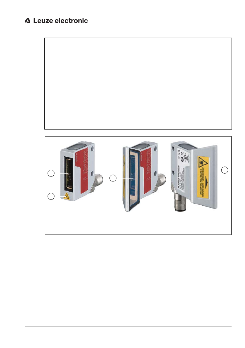
A Laser aperture
B Laser warning sign
A
A
B
B
NOTE
Affix laser information and warning signs!
Laser warning and laser information signs are affixed to the device (see Figure 2.1):
In addition, self-adhesive laser warning and information signs (stick-on labels) are supplied
in several languages (see Figure 2.2).
Affix the laser information sheet to the device in the language appropriate for the place
of use.
When using the device in the U.S.A., use the stick-on label with the "Complies with
21 CFR 1040.10" notice.
Affix the laser information and warning signs near the device if no signs are attached
to the device (e.g., because the device is too small) or if the attached laser information
and warning signs are concealed due to the installation position.
Affix the laser information and warning signs so that they are legible without exposing
the reader to the laser radiation of the device or other optical radiation.
Leuze electronic BPS 8 9
TNT 35/7-24V
Figure 2.1: Laser apertures, laser warning signs
Page 11
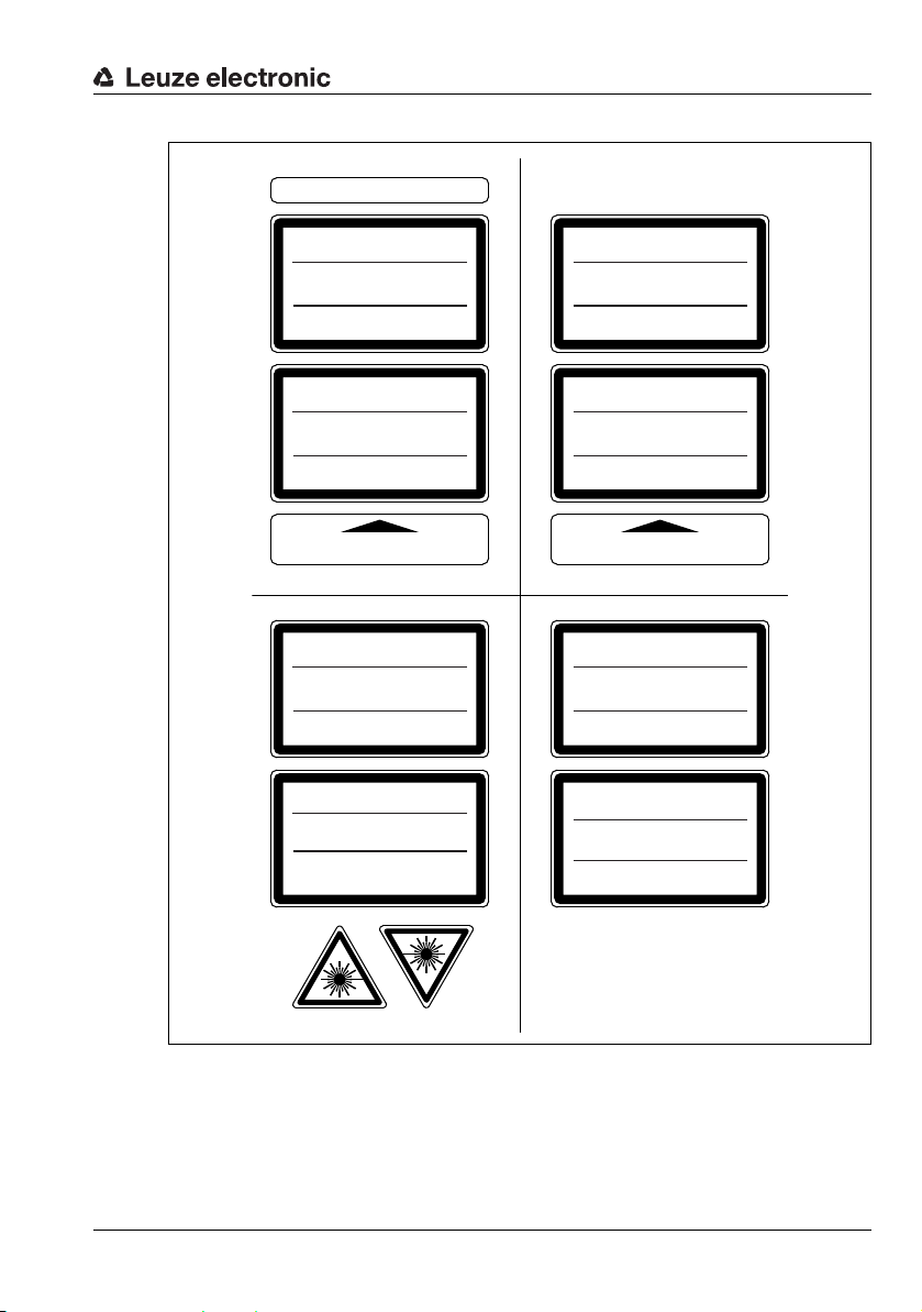
AVOID EXPOSURE – LASER RADIATION
IS EMITTED FROM THIS APERTURE
EXPOSITION DANGEREUSE – UN RAYONNEMENT
LASER EST ÉMIS PAR CETTE OUVERTURE
LASERSTRAHLUNG
NICHT IN DEN STRAHL BLICKEN
LASER KLASSE 2
DIN EN 60825-1:2008-05
Max. Leistung (peak):
Impulsdauer:
Wellenlänge:
RADIAZIONE LASER
NON FISSARE IL FASCIO
APARRECCHIO LASER DI CLASSE 2
EN 60825-1:2007
Potenza max. (peak):
Durata dell'impulso:
Lunghezza d'onda:
LASER RADIATION
DO NOT STARE INTO BEAM
CLASS 2 LASER PRODUCT
EN 60825-1:2007
Maximum Output (peak):
Pulse duration:
Wavelength:
RAYONNEMENT LASER
NE PAS REGARDER DANS LE FAISCEAU
APPAREIL À LASER DE CLASSE 2
EN 60825-1:2007
Puissance max. (crête):
Durée d`impulsion:
Longueur d`onde:
RADIACIÓN LÁSER
NO MIRAR FIJAMENTE AL HAZ
PRODUCTO LÁSER DE CLASE 2
EN 60825-1:2007
Potencia máx. (peak):
Duración del impulso:
Longitud de onda:
RADIAÇÃO LASER
NÃO OLHAR FIXAMENTE O FEIXE
EQUIPAMENTO LASER CLASSE 2
EN 60825-1:2007
Potência máx. (peak):
Período de pulso:
Comprimento de onda:
LASER RADIATION
DO NOT STARE INTO BEAM
CLASS 2 LASER PRODUCT
IEC 60825-1:2007
Complies with 21 CFR 1040.10
Maximum Output (peak):
Pulse duration:
Wavelength:
䉏⏘戟⺓
▎䦃展⏘㧮
伊䉏⏘ℶ❐
GB7247.1-2012
㦏⮶戢⒉᧤⽿⋋᧥
厘⑁㖐兼㢅梃
㽱栎
1,7 mW
<420 μs
655 nm
1,7 mW
<420 μs
655 nm
1.7 mW
<420 μs
655 nm
1,7 mW
<420 μs
655 nm
1,7 mW
<420 μs
655 nm
1,7 mW
<420 μs
655 nm
1.7 mW
<420 μs
655 nm
1.7 mW
<420 μs
655 nm
50038277-03
Safety
Figure 2.2: Laser warning and information signs – supplied stick-on labels
TNT 35/7-24V
Leuze electronic BPS 8 10
Page 12

3 Technical data of BPS 8
3.1 General specifications BPS 8
Optical data
Light source Laser diode
Beam deflection Via rotating polygon wheel
Reading distance See reading field (Figure 3.3 and Figure 3.4 on Page 15)
Optical window Glass
Laser class 2 acc. to IEC 60825-1:2007
Wavelength 655nm
Max. output power (peak) 1.7mW
Impulse duration < 420 µs
Measurement data
Reproducible accuracy ±0.15 … ±1mm depending on device version
Response time 26.6ms (configurable)
Output time 3.3ms
Basis for contouring error calculation
Working range BPS 8 SM 102: 80 … 140mm
Max. traverse rate 4 m/s
Electrical data
Operating voltage
Power consumption BPS 8: 1.5W
Interface type RS 232 directly or in combination with MA 8.1,
Service interface RS 232 directly on the BPS 8,
Switching input /
switching output
Green LED Device ready (power on)
Mechanical data
Degree of protection IP 67
Weight 70g
Dimensions (H x W x D) 48 x 40.3 x 15mm (BPS 8 SM 102…),
Housing Diecast zinc
1)
13.3ms
BPS 8 SM 100: 60 … 120mm
BPS 8: 4.9 … 5.4VDC
With MA 8…: 10 … 30VDC
With MA 8…: max. 2W
RS 485 in combination with MA 8-01/MA 8-02
RS 232 via MA 8.1,
RS 485 via MA 8-01/MA 8-02,
with default data format:
9.6 kBit/s, 8 data bits, no parity, 1 stop bit
1 switching input, 1 switching output, each is programmable,only in combination with MA 8…
61 x 51 x 17.4mm (BPS 8 SM 100…)
Technical data of BPS 8
TNT 35/7-24V
Leuze electronic BPS 8 11
Page 13

Technical data of BPS 8
Environmental data
Operating temperature range 0 °C … -40 °C
Storage temperature range -20 °C … -60 °C
Air humidity Max. 90 % rel. humidity, non-condensing
Vibration IEC 60068-2-6, test Fc
Shock/continuous shock IEC 60068-2-27, test Ea
Electromagnetic compatibility EN 61000-6-2:2005+AC:2005,
Conformity CE, CDRH
Certifications
1) 2)
Bar code tape
Max. length (measurement
length)
Ambient temperature -40 °C … -120 °C
Mech. properties Scratch and wipe resistant, UV resistant,
1) For UL applications: use is permitted exclusively in Class 2 circuits according to NEC
2) These sensors shall be used with UL Listed Cable assemblies rated 30V, 0.5A min, in the
field installation, or equivalent (categories: CYJV/CYJV7 or PVVA/PVVA7)
3) Depends on the transmission protocol and on the configured resolution.
Table 3.1: General specifications
EN 61000-6-3:2007+A1:2011+AC:2012
UL 60950-1, CSA C22.2 No.60950-1
10,000 m
3)
moisture resistant, partly chemical resistant
Leuze electronic BPS 8 12
TNT 35/7-24V
Page 14
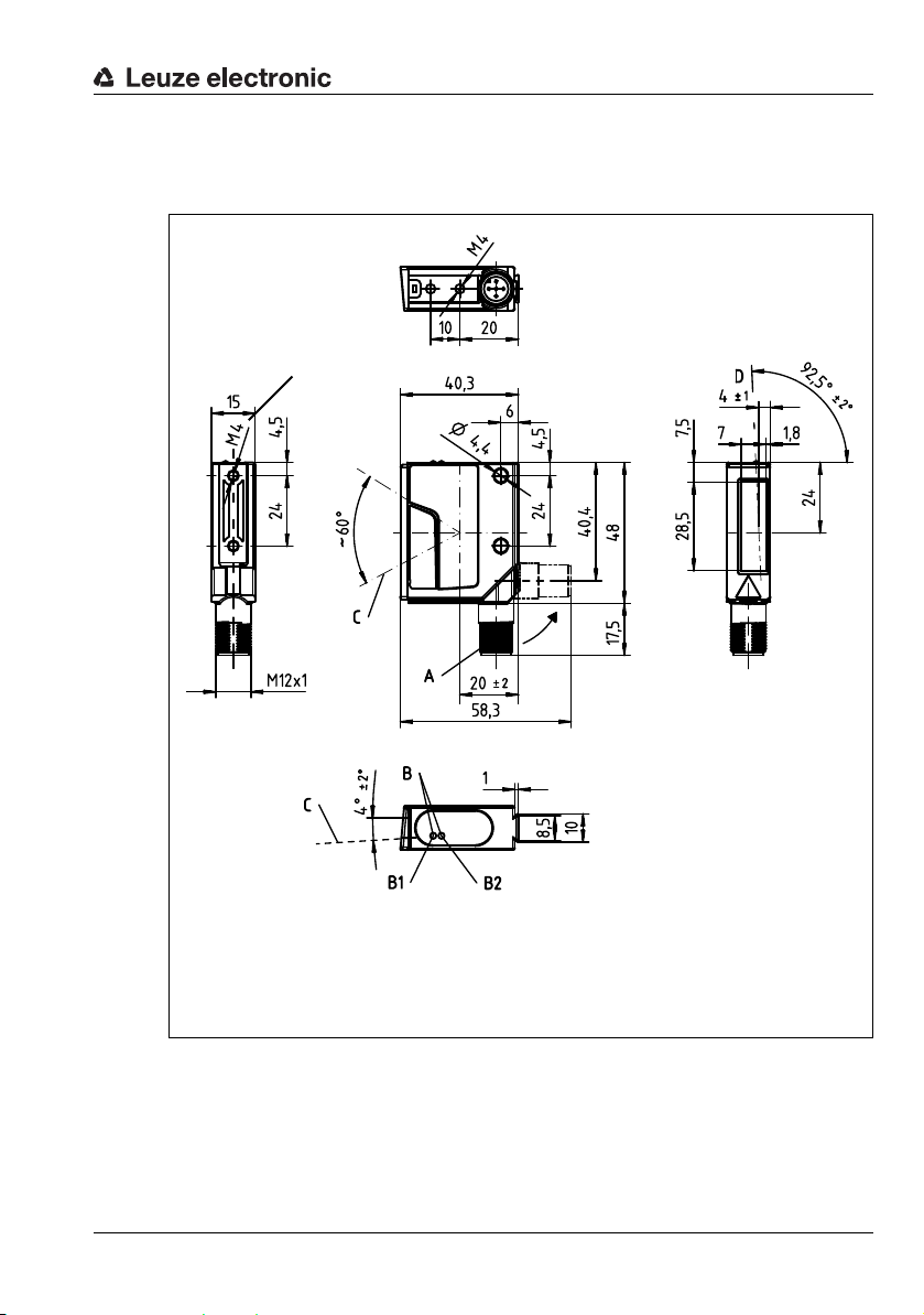
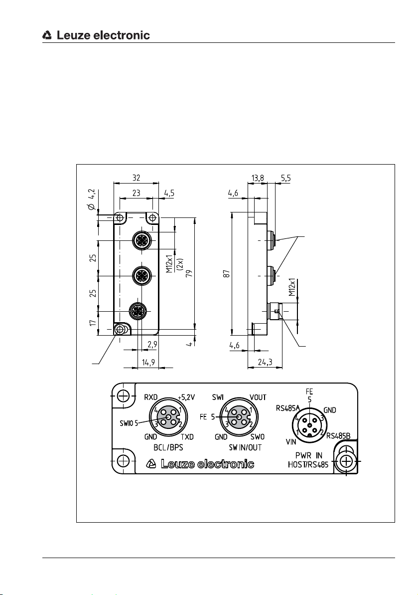
3.2 Dimensioned drawings
A Turning connector, turnable 90°
B Indicator diodes (B1: status LED, B2: decode LED)
C Scanning beam, divergence max. 5mm at 150 mm reading distance
D Optical axis
Thread depth:
3mm
Thread depth:
3mm
BPS 8 SM 102… with front beam exit
Technical data of BPS 8
Figure 3.1: BPS 8 SM 102… dimensioned drawing
Leuze electronic BPS 8 13
TNT 35/7-24V
Page 15
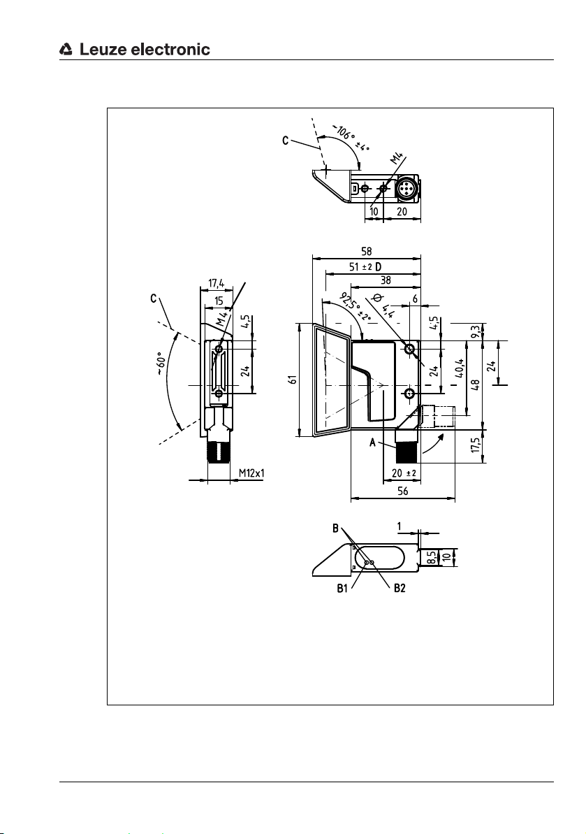
BPS 8 SM 100… with lateral beam exit
A Turning connector, turnable 90°
B Indicator LEDs (B1: status LED, B2: decode LED)
C Scanning beam, divergence max. 5mm at 150 mm reading distance
D Optical axis
Thread depth:
3mm
Thread depth:
3mm
Technical data of BPS 8
Figure 3.2: BPS 8 SM 100-01 dimensioned drawing
Leuze electronic BPS 8 14
TNT 35/7-24V
Page 16
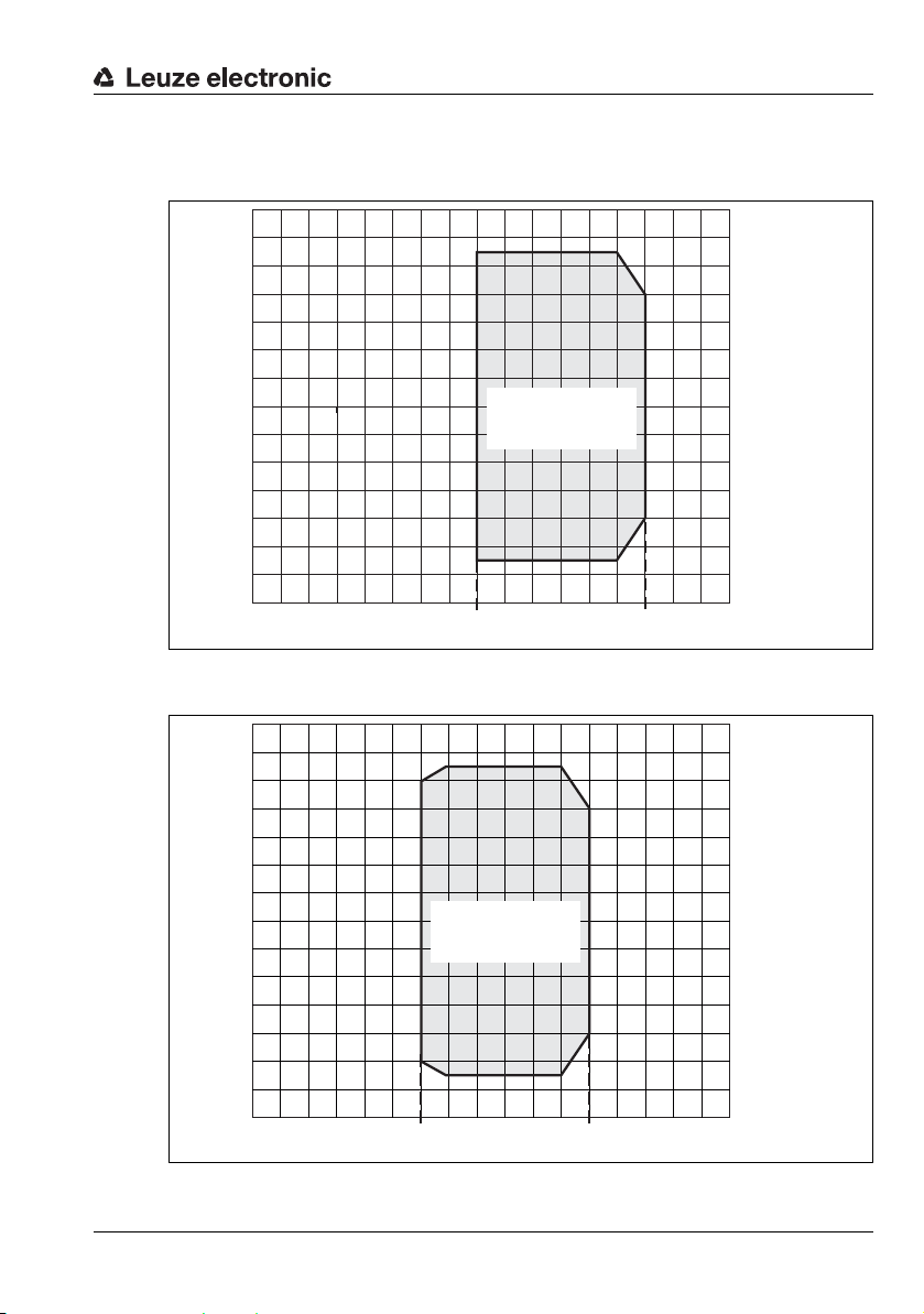
3.3 Reading field curves
-70
-60
-50
-40
-30
-20
-10
0
10
20
30
40
50
60
70
0 1020304050607080 90 100 110 120 130 140 150 160
170
Reading distance [mm]
Reading field width [mm]
Working range
BPS 8 SM 102
Reading distance [mm]
Reading field width [mm]
Working range
BPS 8 SM 100
BPS 8 SM 102 with front beam exit
Figure 3.3: Reading field curve BPS 8 SM 102 with front beam exit
BPS 8 SM 100 with lateral beam exit
70
60
50
40
30
20
Leuze electronic BPS 8 15
10
0
-10
-20
-30
-40
-50
-60
-70
0 102030405060 70 80 90 100 110 120 130 140 150 160
Figure 3.4: Reading field curve BPS 8 SM 100 with lateral beam exit
Technical data of BPS 8
TNT 35/7-24V
170
Page 17

MA 8… / MA 2xxi connection units
4 MA 8… / MA 2xxi connection units
Various connection units are available for convenient electrical connection:
• MA 8.1 RS 232 interface Operating voltage 10 … 30V DC
• MA 8-01 RS 485 interface Operating voltage 10 … 30VDC
• MA 8-02 RS 485 interface Operating voltage 10 … 30VDC
• MA 2xxi Different fieldbus systems Operating voltage 18 … 30V DC
MA 8-01 and MA 8-02 differ in the resistor network for the termination of the RS 485 interface:
• MA 8-01 390 / 220 / 390
• MA 8-02 47k / 150 / 47 k
You can find connection and interconnection cables of varying lengths in Chapter 12.5
"Accessories – Cables" on page 117.
Leuze electronic BPS 8 16
TNT 35/7-24V
Page 18
4.1 MA 8.1 connection unit
A
B
C
A M12 socket, 5-pin, A-coded
B M12 connector, 5-pin, A-coded
C FE connection
all dimensions in mm
The MA 8.1 modular connection unit is an optional accessory for the connection of a BPS 8
to a DC voltage supply of 10 to 30 V DC. If offers the following advantages over the installation of the BPS 8 as a stand-alone device:
• M12 socket for switching input and switching output
• M12 connector for RS 232 interface and voltage supply 24VDC
• M12 socket for connection of the BPS 8
MA 8… / MA 2xxi connection units
Figure 4.1: Dimensioned drawing and pin assignment of the MA 8.1 connection unit
Leuze electronic BPS 8 17
TNT 35/7-24V
Page 19
4.2 MA 8-01 / MA 8-02 connection unit
A
B
C
A M12 socket, 5-pin, A-coded
B M12 connector, 5-pin, A-coded
C FE connection
all dimensions in mm
The modular connection unit is an optional accessory when connecting a BPS 8 to an
RS 485 interface. The RS 485 interface, the switching input and the switching output are all
connected to the MA 8-01/MA 8-02. It also supplies voltage to the BPS 8. The MA 8-01/
MA 8-02 connection unit offers the following advantages over the installation of the BPS 8
as a stand-alone device:
• M12 socket for switching input and switching output
• M12 connector for RS 485 interface and voltage supply 24VDC
• M12 socket for connection of the BPS 8
MA 8… / MA 2xxi connection units
Figure 4.2: Dimensioned drawing and pin assignment of the MA 8-01/MA 8-02 connection
Leuze electronic BPS 8 18
TNT 35/7-24V
Page 20

unit
MA 8… / MA 2xxi connection units
Leuze electronic BPS 8 19
TNT 35/7-24V
Page 21

4.3 MA 2xxi connection unit
The MA 2xxi modular connection unit is a gateway for the BPS 8 for connecting to various
fieldbus systems and Ethernet networks.
In this setup, the data of the BPS 8 is transmitted through the RS 232 interface to the
MA 2xxi and implemented there on the relevant fieldbus/Ethernet systems.
The following gateways are available for the BPS 8:
• MA 204i PROFIBUS DP
• MA 208i Ethernet
• MA 248i PROFINET
• MA 235i CANopen
• MA 238i EtherCAT
• MA 255i DeviceNet
• MA 258i Ethernet/IP
You can find more detailed information on the gateways at www.leuze.com.
MA 8… / MA 2xxi connection units
Leuze electronic BPS 8 20
TNT 35/7-24V
Page 22
5 Bar code tape
5.1 General information
The bar code tape is available in different variants:
• BCB bar code tape with 40 mm grid, Code128 with character set C, increasing in
increments of 4 (e.g., 000004, 000008, … )
• BCB8 bar code tape with 30 mm grid, Code128 with character set C, increasing in
increments of 3 (e.g., 000003, 000006, … )
CAUTION
Bar code tape!
BPS 8 is set for bar code tape BCB8 with a 30 mm grid by default.
The BPS 8 can be configured for position measurement with a 40 mm bar code tape with
the BPS Configuration Tool.
A bar code tape consists of a sequence of individual position bar codes in one of the two
grids. Defined cut marks are provided for cutting the BCB.
The bar code tape is delivered on a roll. A roll contains up to 200 m of BCB. The BCB always
starts with the lowest position value at the outside of the roll (this is the value ’000000’ for
standard tapes). The BCB ends at the inside on the wrapping core with the largest position
value. If more than 200 m of BCB is ordered, the total length is divided into rolls of 200 m.
Bar code tapes with special requirements with respect to height, length and value range can
be ordered from Leuze electronic (see chapter 12.2 "Type overview: Bar code tape").
Bar code tape
NOTE
Value range for BCB with special requirements!
When ordering bar code tapes with special requirements, make certain that the value
range contains only values that are divisible by three (BCB8 with 30 mm grid).
It may otherwise not be possible to purchase and use repair tapes.
NOTE
Only one BCB type per system!
In a given system, use either only BCB8 with 30 mm grid or only BCB with 40 mm grid.
If different BCB grids are used in one system, the BPS cannot ensure an exact position
determination.
Leuze electronic BPS 8 21
TNT 35/7-24V
Page 23
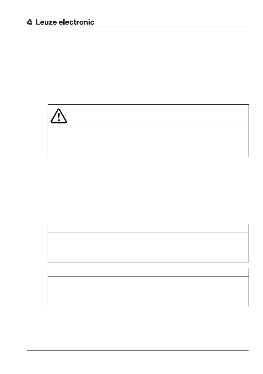
Bar code tape BCB8 with 30 mm grid
A
B
A Position bar code with position value
B Cut mark
30 mm
Bar code tape
BCB8 BCB8
000036 000039 000042 000045 000048 000051
BCB8
BCB8 BCB8
BCB8
Figure 5.1: Bar code tape BCB8 with 30 mm grid
The standard height of 47 mm can be adapted. Other BCB heights (25 mm and 30 mm) and
special heights on request.
With a standard bar code tape and repair tape with 30 mm grid, the printed numerical values
are divisible by three without a remainder. For bar code tapes with 30 mm grid, the designation BCB8 is printed in plain text in addition to the position value.
TNT 35/7-24V
Leuze electronic BPS 8 22
Page 24
5.2 Control bar codes
BCB8 BCB8
BCB8
BCB8
BCB8
A
B
A Control bar code
B The control bar code is decoded in the marked scans
With the help of control bar codes that are affixed on top of the bar code tape at appropriate
positions, functions in the BPS can be activated or deactivated, e.g. precise, reproducible
switching between different BCB value ranges at switches.
Code type Code128 with character set B is used for the control bar code.
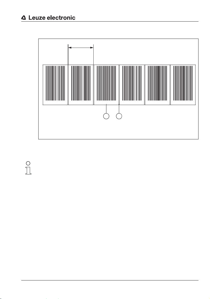
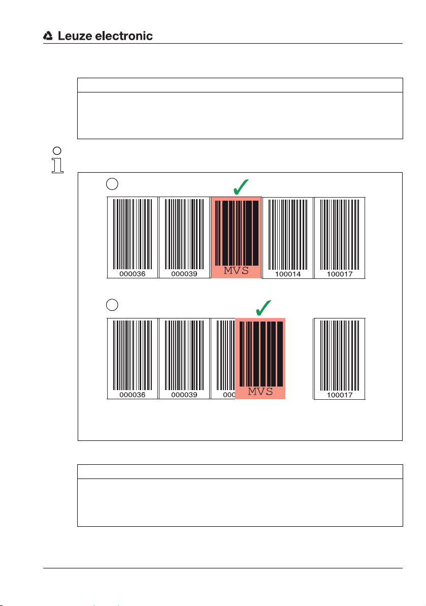
The MVS label is a control bar code for the precise, reproducible switching of position values
from a preceding to a subsequent bar code tape. The subsequent bar code tape begins with
another, new value range.
The changeover between the different value ranges of the two BCBs occurs independent of
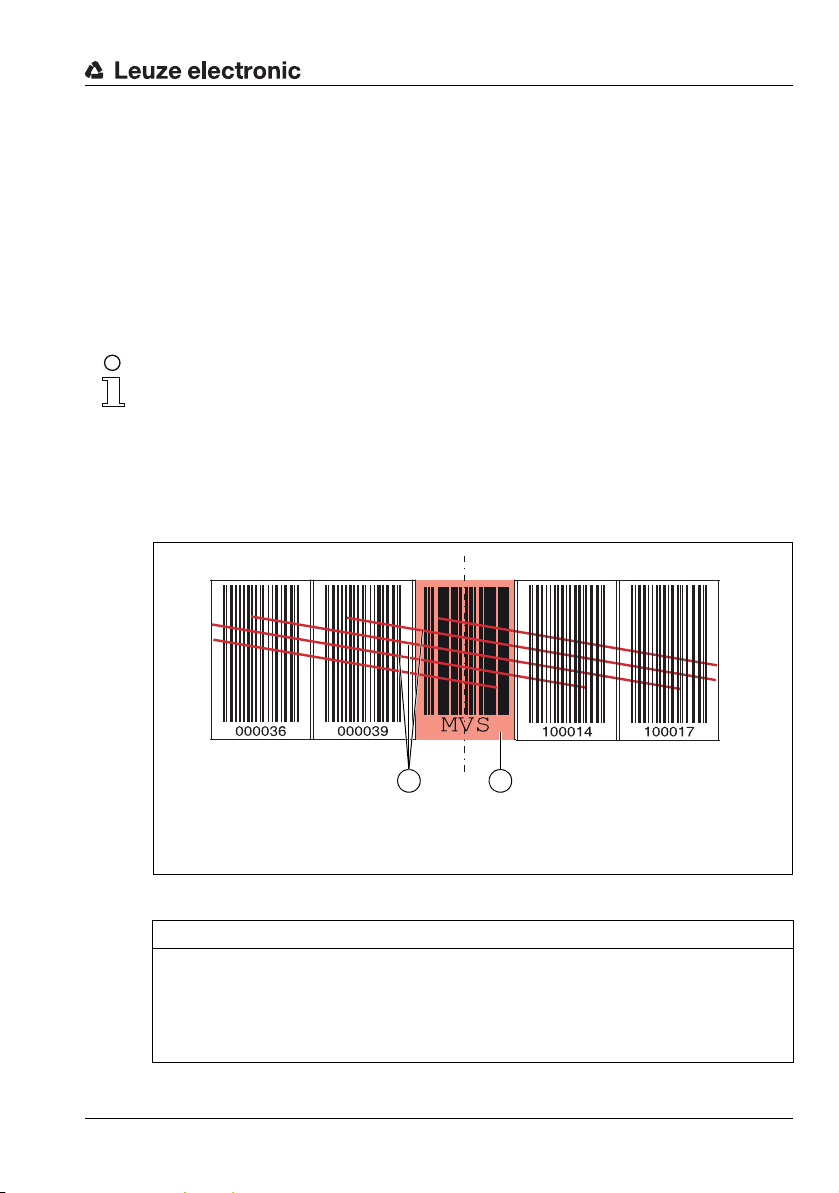
the direction of travel in the center of the MVS control bar code.
If, upon reaching the the center of the MVS control bar code, the BPS 8 does not detect the
value range of the subsequent BCB in the scanning beam, the position value of the first BCB
section is still output for half of the label width starting from the center of the MVS control bar
code.
Arrangement of the control bar codes
The control bar code is attached in such a way that it replaces one position bar code or
seamlessly connects two bar code tapes with different value ranges to one another ((see
figure 5.2)).
Bar code tape
Figure 5.2: Arrangement of the MVS control bar code
NOTE
Distance between two control bar codes!
Make certain that there is only one control bar code (or marker bar code) in the scan-
ning beam at a time.
The minimum distance between two control bar codes is determined by the distance
between the BPS 8 and bar code tape and the resulting length of the scanning beam.
Leuze electronic BPS 8 23
TNT 35/7-24V
Page 25
Bar code tape
BCB8 BCB8
BCB8
BCB8
BCB8
BCB8 BCB8
BCB8
BCB8
A
B
A Control bar code perfectly affixed on the bar code tape
B Control bar code at small gap between two bar code tapes
The control bar codes are simply affixed over the existing bar code tape.
NOTE
Grid dimension of control/marker bar code!
The control/marker bar code must match the selected grid of the bar code tape used. If a
30 mm grid is used (default), then the control/marker bar code must also be inserted in the
30 mm grid. With a 40 mm grid, a 40 mm control/marker bar code is used.
Keep the gap between the BCBs that are switched between as small as possible.
Figure 5.3: Correct positioning of the control bar code
NOTE
Gaps in bar code tape!
Avoid polished and high-gloss surfaces.
Keep the gaps between the two bar code tapes and the control bar code as small as
possible.
Leuze electronic BPS 8 24
TNT 35/7-24V
Page 26
Bar code tape
MVS control bar code
With the MVS control bar code, there is precise and reproducible switching between two bar
code tapes with different value ranges.
NOTE
1 m minimum distance of the bar code values for measurement value switching!
For different BCB value ranges, make certain that a minimum distance of the printed
value range of 1 m between the preceding position bar code (before the control bar
code) and the subsequent position bar code (after the control bar code) is maintained.
Example: If the last position bar code on the BCB8 before the control bar code is
’075120’, the following position bar code on the BCB8 after the control bar code must
be at least ’075222’ (printed values BCB8 in cm).
If the minimum value range distance of 1 m between the bar code values is not maintained, position determination may be faulty.
• The end of the preceding bar code tape and the start of the subsequent bar code tape
can end and begin, respectively, with completely different position bar codes.
• BCB changeover by means of a control bar code always occurs at the same position,
i.e., it serves to change from the preceding tape to the subsequent tape and vice
versa.
• If the center of BPS 8 reaches the center of the MVS control bar code at the transition
position, the value range of the subsequent BCB is switched to – provided the BPS 8
has the next position bar code in the scanning beam(see figure 5.4).
This means the output position value is always uniquely assigned to the preceding or
subsequent BCB.
If, upon reaching the the center of the MVS control bar code, the BPS 8 does not detect the
value range of the subsequent BCB in the scanning beam, the position value of the first BCB
section is still output for half of the label width starting from the center of the MVS control bar
code.
Leuze electronic BPS 8 25
TNT 35/7-24V
Page 27
Bar code tape
BCB8 BCB8
BCB8
BCB8
BCB8
A
B
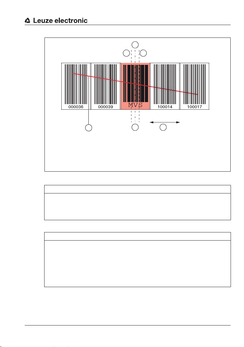
A Scanning beam
B Control bar code center
C BPS 8 center
D Direction of movement
E MVS hysteresis range
D
C
E E
Figure 5.4: Measurement range changeover via MVS control bar code
NOTE
Measurement range changeover!
The measurement range changeover from the preceding to the subsequent BCB occurs
when the center of the BPS 8 (C in Figure 5.4) is opposite the center of the control bar
code (B in Figure 5.4).
NOTE
Hysteresis for measurement range changeover!
If a measurement range changeover occurs in the center of the MVS control bar code to
the subsequent BCB, a hysteresis range of ± 2mm (E in Figure 5.4) is activated.
If the direction of movement is reversed within this hysteresis range, a measurement range
changeover occurs to the preceding BCB 15 mm after the center of the MVS control bar
code.
Within this range of 15 mm, the position values are calculated from the subsequent BCB.
TNT 35/7-24V
Leuze electronic BPS 8 26
Page 28

5.3 Marker bar codes
BCB8
BCB8
BCB8 BCB8
BCB8
A
A Marker bar code
Marker bar codes, which are affixed at the appropriate locations via a position bar code, can
be used to trigger various functions in the superior control. The BPS 8 detects the defined
marker bar codes in the scanning beam, decodes them, and makes them available to the
control.
NOTE
Distance between two marker bar codes!
Make certain that there is only one marker bar code (or control bar code) in the scan-
ning beam at a time.
The minimum distance between two marker bar codes is determined by the distance
between the BPS 8 and bar code tape and the resulting length of the scanning beam.
Definition of the marker bar code
The following combinations of letters and numbers may be used as marker bar codes:
• First character: Capital letter A, B, C, D or Z
• Second character: Digit from 0…9
• Third character: Digit from 0…9
Structure of the marker bar codes
Code type Code128 with character set B is used for the marker bar code.
Arrangement for using the marker bar code with position bar codes
The marker bar code must be attached to the bar code tape aligned with the grid of the
actual coding. A position bar code should be detected by the scanning beam before and
after the marker bar code.
Bar code tape
Leuze electronic BPS 8 27
Figure 5.5: System arrangement of marker bar code
TNT 35/7-24V
Page 29

Bar code tape
Arrangement for using the marker bar code without position bar codes
The marker bar code must be positioned within the BPS 8's detection range.
NOTE
If position bar codes are arranged in the detection area of the scanning beam before and
after the marker bar code, the position calculation is continued without interruption.
Leuze electronic BPS 8 28
TNT 35/7-24V
Page 30

5.4 Technical data of the BCB8 bar code tape
Dimensions
Grid 30mm
Standard height 47mm
Special heights 25mm, 30mm, more special heights on request
Length 0 … 5m, 0 … 10m, 0 … 20m, …, 0 … 150m,
Tape tolerance ±1 mm per meter
Structure
Surface protection Polyester, matt
Base material Polyester film, affixed without silicone
Adhesive Acrylate adhesive
Strength of adhesive 0.1mm
Environmental data
Processing temperature
received
Temperature resistance -40 °C … -120 °C
Dimensional stability No shrinkage, tested according to DIN 30646
Curing Final curing after 72h,
Weathering resistance UV light, humidity,
Chemical resistance
(checked at 23 °C over 24 h)
Behavior in fire Self-extinguishing after 15 s, does not drip
Surface Grease-free, dry, clean, smooth
Mechanical properties Scratch and wipe resistant, UV resistant,
Table 5.1: Technical data of the BCB8 bar code tape
(see chapter 12.2 "Type overview: Bar code tape")
0 °C … -45 °C
the BPS 8 can detect the position immediately after the
BCB is affixed
salt spray fog (150 h/5 %)
Transformer oil, diesel oil, white spirit, heptane,
ethylene glycol (1:1)
moisture resistant, partly chemical resistant
Bar code tape
Leuze electronic BPS 8 29
TNT 35/7-24V
Page 31

Bar code tape
BCB8
BCB8
BCB8
000018 000021 000024
28,7228,72
47 ±0,247 ±0,2
1,281,28
all dimensions in mm
5.5 Dimensioned drawing for position, control and marker bar codes
Figure 5.6: Dimensioned drawing for position, control and marker bar codes in a 30 mm
grid
TNT 35/7-24V
Leuze electronic BPS 8 30
Page 32

6 Mounting and installation
6.1 Mounting the bar code tape
6.1.1 Installation and application remarks
NOTE
BCB mounting
When processing BCBs, observe the specified processing temperatures.
When processing BCBs in cold storage facilities, the BCB must be affixed before cooling the storage facility. However, if it should be necessary to affix the BCB at temperatures outside of the specified processing temperature, assure that the bonding surface as well as the BCB are at the processing temperature.
Avoid dirt deposits on the BCB.
If possible, affix the BCB vertically. If possible, affix the BCB below an overhead covering.
The BCB must never be continuously cleaned by on-board cleaning devices such as
brushes or sponges. Permanent on-board cleaning devices polish the BCB and give
it a glossy finish. The reading quality deteriorates as a result.
After affixing the BCBs, make certain that there are no polished, high-gloss surfaces
in the scanning beam (e.g., glossy metal at gaps between the individual BCBs), as the
measurement quality of the BPS may be impaired.
Affix the BCBs to a diffusely reflective support, e.g., a painted surface.
Avoid sources of extraneous light and reflections on the BCB.
Ensure that neither strong sources of extraneous light nor reflections of the support on
which the BCB is affixed occur in the vicinity of the BPS scanning beam.
Affix the BCB over expansion joints up to a width of several millimeters.
The BCB must not be interrupted at this location.
Cover protruding screw heads with the BCB.
Ensure that the BCB is affixed without tension.
The BCB is a plastic tape that can be stretched by strong mechanical tension. Excessive mechanical stretching results in lengthening of the tape and distortion of the position values.
Mounting and installation
TNT 35/7-24V
Leuze electronic BPS 8 31
Page 33

Mounting and installation
NOTE
BCB application
Make certain that the BCB is located in the scanning beam of the BPS over the entire
traversing path.
The BPS can determine the position on BCBs with arbitrary orientation.
Bar code tapes with different value ranges may not directly follow one another.
In the case of different value ranges, a gap of at least 1 m must be maintained between
the last position bar code value of the preceding BCB and the first position bar code
value of the subsequent BCB (see Chapter 5.2).
For MVS control bar codes (see Chapter 5.2), the minimum distance of 1 m between
the printed value of the last position bar code before the control bar code and the
printed value of the first position bar code after the control bar code must be maintained (BCB8 printed values in cm).
In the case of bar code tapes with different value ranges, both BCBs must be
BCB8-type in a 30 mm grid (see Chapter 5.1).
When using the position bar code with the value ’000000’, negative values are output
for position measurements to the left of the label.
Leuze electronic BPS 8 32
TNT 35/7-24V
Page 34

6.1.2 Cutting bar code tapes
A
A Cut mark
NOTE
Bridging gaps!
Any mechanical gaps may have to be bridged when affixing the bar code tape.
Smaller gaps (up to around 10mm) can be covered with the tape.
For wider gaps we recommend cutting out the label over the gap at the marked cut
mark.
In chemically aggressive environments, the bar code tape should be cut out over
mechanical gaps. Since the tape is highly resistant to chemical loads only on the front
side, exposure of the adhesive side should be avoided.
If necessary, the BCB is cut at the indicated cut marks ((see figure 6.1)).
Mounting and installation
BCB8 BCB8
000036 000039 000042 000045 000048 000051
BCB8
BCB8 BCB8
Figure 6.1: Cut mark on the bar code tape
Leuze electronic BPS 8 33
BCB8
TNT 35/7-24V
Page 35

Mounting and installation
A Preceding bar code tape
B Cut mark
C Subsequent bar code tape, value of the last bar code of the preceding bar code
tape + 1 m
B
C
A
If another BCB is to be affixed directly after the preceding BCB, the subsequent bar code
value must differ from the preceding bar code value by at least 1 m (BCB8 printed values in
cm, see Figure 6.2).
BCB8 BCB8 BCB8
BCB8
BCB8 BCB8
Figure 6.2: Cut bar code tape
NOTE
Use MVS control bar code!
For this arrangement (Figure 6.2) using the MVS bar code is recommended.
With the MVS control bar code, a unique, reproducible switching point between the two
different position bar codes is achieved, irrespective of the direction of travel.
Without the MVS control bar code, the switching point is subject to hysteresis in the event
of alternating directions of travel (see chapter 5.2 "Control bar codes").
TNT 35/7-24V
Leuze electronic BPS 8 34
Page 36

Mounting and installation
A Preceding bar code tape
B Cut mark
C Gap, at least 300 mm
D Subsequent bar code tape
B
C
A
B
D
If the bar code tape cannot be affixed without interruption, the tape-free gap should be wider
than 300 mm. When passing over the gap, the scanning beam can therefore always only
read the preceding or subsequent position bar code.
Make sure that when starting the bar code tape after the gap approx. 10 position bar codes
are cut off, because there may otherwise be an output of the same position values before
and after the gap.
BCB8 BCB8
BCB8
000072 000075 000078
BCB8 BCB8
Figure 6.3: Cut bar code tape
NOTE
No glossy gaps in the cut bar code tape!
Ensure that there are matt, bright surfaces behind the gaps in the BCB.
Polished, reflective, and high-gloss surfaces in the scanning beam may impair the
measurement quality of the BPS.
TNT 35/7-24V
Leuze electronic BPS 8 35
Page 37

6.1.3 Mounting the BCB
Mount the BCB as follows:
Check the surface.
It must be flat, free of grease and dust, and be dry.
Define a reference edge (e.g., metal edge of the busbar).
Remove the backing and affix the BCB along the reference edge tension free.
Secure the bar code tape to the mounting surface by pressing down with the palm of
your hand.
When affixing, make certain that the BCB is free of folds and creases and that no air
pockets form.
NOTE
When mounting, do not pull on the BCB!
The BCB is a plastic tape that can be stretched by strong mechanical tension. The
stretching results in lengthening of the tape and distortion of the position values on the
BCB.
While the BPS can still perform the position calculation in the event of distortions, the
absolute measurement accuracy is no longer ensured in this case. If the values are
taught using a teach-in process, stretching of the BCB is irrelevant.
If a bar code tape was damaged, e.g., by falling parts, you can download a repair kit for the
BCB from the Internet (see chapter 6.1.4 "BCB repair with repair kit").
Use the bar code tape created with the repair kit only temporarily as an emergency solution.
Mounting and installation
Leuze electronic BPS 8 36
TNT 35/7-24V
Page 38

Mounting and installation
A BPS 8
B Reading distance
C Bar code tape radius, R
min.
= 300 mm
C
A
B
BCB mounting in horizontal curves
NOTE
Limited absolute measurement accuracy and reproducibility!
Installing the BCB in bends impairs the absolute precision of the BPS, because the
grid dimension can no longer be detected as 30 mm due to the optical distortion of
the bar code.
For horizontal curves, maintain a minimum bending radius of 300 mm ((see figure 6.4)).
Figure 6.4: Mounting the bar code tape for use in horizontal curves
Leuze electronic BPS 8 37
TNT 35/7-24V
Page 39

Mounting and installation
BCB8
BCB8
BCB8
BCB8
BCB8
BCB mounting in vertical curves
NOTE
Limited absolute measurement accuracy and reproducibility!
BCB mounting in curves decreases the absolute measurement accuracy of the BPS,
since the distance between two bar codes is no longer exactly 30 mm.
In areas where the BCB is fanned out around curves, limitations of the reproducibility
must be expected.
Only partially cut the BCB at the cut mark.
Affix the BCB along the curve like a fan ((see figure 6.5)).
Ensure that the BCB is affixed without mechanical tension.
NOTE
No glossy gaps in the bar code tape!
Ensure that there are matt, bright surfaces behind the fanning in the BCB curves.
Polished, reflective, and high-gloss surfaces in the scanning beam may impair the
measurement quality of the BPS.
Figure 6.5: Preparing the bar code tape for use in vertical curves
Leuze electronic BPS 8 38
TNT 35/7-24V
Page 40

6.1.4 BCB repair with repair kit
NOTE
Do not use the BCB repair kit on a permanent basis!
Use the bar code tape created with the repair kit only temporarily as an emergency
solution.
The optical and mechanical properties of the self-printed bar code tape do not correspond to those of the original bar code tape.
Self-printed bar code tape should not remain in the system on a permanent basis.
Original repair tapes in lengths of 1 m can be ordered from Leuze electronic on
request.
If a bar code tape was damaged, e.g., by falling parts, you can download a repair kit for the
BCB from the Internet.
www.leuze.com > Products > Measuring Sensors > Sensors for Positioning > Bar
code positioning systems > BPS 8 > (Name of the BPS 8) > Tab Downloads > Repair
kit.
In the repair kit files, you will find all position values with 30 mm grid.
The repair kit PDF files each contain a value range of 500m. The following value ranges are
available:
• 0 … 500m
• 500 … 1000m
• 1000 … 1500m
etc. up to
• 9500 … 9999m
You can find the repair kit PDF files with position bar codes in a 40 mm grid in the download
area of our BPS 300i bar code positioning systems.
Mounting and installation
Leuze electronic BPS 8 39
TNT 35/7-24V
Page 41

Mounting and installation
BCB8 BCB8
BCB8
BCB8 BCB8
BCB8
000036 000039 000042 000045 000048 000051
30 mm
Replacing a section of defective bar code tape
Determine the values of the defective position bar codes using the value printed in plain
text. If this value is no longer legible, the position value of the next position bar code can
be determined from the last legible value in the continuing 3 cm grid dimension.
Download the required repair kit PDF file, look for the page(s) with the required position
bar codes and print them out.
Trim the required position bar codes and affix them over the defective positions of the
bar code tape.
NOTE
Printing coding
Select only those pages that are actually required.
Change the printer settings so that the bar code is not distorted.
Check the print results and measure the distance between two bar codes ((see
figure 6.6))
Cut the code strips and arrange them next to one another. The code content must
always increase or decrease in increments of 30 mm. Check that the printed values
increase by 3.
Figure 6.6: Checking the print results of the BCB8 repair kit (30 mm grid)
Leuze electronic BPS 8 40
TNT 35/7-24V
Page 42

6.2 Mounting the BPS 8
A
B
A Reading window with front beam exit
B Reading window with lateral beam exit
C Ø 4.4mm through holes for mounting
D Dovetails and two M4 mounting threads at the rear and bottom side of the device
E M12 connector, turnable
D
C
D
C
E E
BPS 8 SM 102 BPS 8 SM 100
D D
There are different types of mounting arrangements for the BPS 8:
1. Directly, using the 2 through holes in the housing.
2. Using the BT 8-01 mounting device on the through holes.
3. Using the BT 8-0 mounting device on the dovetail.
Mounting and installation
Figure 6.7: BPS 8 mounting options
CAUTION
Leuze electronic BPS 8 41
For the position calculation, the scanning beam of the BPS 8 must be incident on
the bar code tape without interruption. Ensure that the scanning beam is always
incident on the BCB when the system is moving.
TNT 35/7-24V
Page 43

BPS 8 system components to be attached/installed
Figure 6.8: BPS 8 system components
Mounting and installation
Leuze electronic BPS 8 42
TNT 35/7-24V
Page 44

6.2.1 BT 8-01 mounting device
A Reference plane for a BCB height of 47 mm
B Fastening holes for a BCB height of 47mm
C Reference plane for a BCB height of 30mm and 25mm
D Fastening holes for a BCB height of 30mm and 25 mm
The BT 8-01 mounting device is available for mounting the BPS 8 using the 2 through holes.
It is intended for attachment via two M4 screws. For order guide, please refer to Chapter
12.6 on Page 118.
Mounting and installation
Figure 6.9: BT 8-01 mounting device
Leuze electronic BPS 8 43
TNT 35/7-24V
Page 45

6.2.2 BT 8-0 mounting device
The BT 8-0 mounting device is available to you for the clamp-mounting of the BPS 8 to the
dovetail on the rear of the device and the bottom of the device. It is intended for fastening at
system via two M4 screws. For order guide, please refer to Chapter 12.6 on Page 118.
NOTE
The angles of inclination required for device arrangement are not integrated with this
mounting device, in contrast with the BT 8-01.
Mounting and installation
Figure 6.10: BT 8-0 mounting device
Leuze electronic BPS 8 44
TNT 35/7-24V
Page 46

6.3 Device arrangement
Selecting a mounting location
NOTE
Select the mounting location
The distance between BPS and bar code tape must be in the working range of the
reading field curve.
Make certain that the required environmental conditions (humidity, temperature, ambi-
ent light) are maintained.
The scanning beam of the BPS should cover three or more position bar codes.
Make certain that the exit window does not become soiled, e.g., by leaking liquids,
abrasion from cardboard packaging or residues from packaging material.
BPS mounting outdoors:
Mount the BPS in a way which provides maximum thermal isolation. Mount the BPS
so that it is protected from airflow, e.g., in a protective housing.
In the event of frost on the bar code tape, no position values can be output.
In the event of direct sunlight on the bar code tape or the BPS 8 during the reading
process, no position value can be output.
The BPS 8 is designed for operating temperatures of 0°C–40°C. Beyond those operating temperatures, one can expect no position values to be output.
Mounting the BPS in a protective housing:
When installing the BPS in a protective housing, ensure that the scanning beam can
exit the protective housing without obstruction.
Make certain that the scanning range determined from the scanning curve is adhered
to at all locations where a position determination is to be made.
Ensure that the scanning beam is always incident on the BCB when the system is
moving.
For the position calculation, the scanning beam of the BPS must be incident on the
BCB without interruption. For the best functionality, the BPS must be guided parallel
to the BCB. It is not permitted to move outside of the approved working range of the
BPS (see chapter 3.3 "Reading field curves" on Page 15) while the system is in motion.
Make certain that there is only one control or marker bar code in the scanning beam
at a time.
The minimum distance between two control bar codes is determined by the distance
between the BPS and bar code tape and the resulting length of the scanning beam.
Mounting and installation
TNT 35/7-24V
Leuze electronic BPS 8 45
Page 47

Mounting and installation
45 mm
4°
±
2°
12°
±
2.5°
82°
±
0.5°
BPS 8 SM 102
A
B
D
C
E
C
A Bar code tape
B Reference plane
C Pitch of scanning beam:
= 10° for a tape height of 47mm
= 5° for a tape height of 30mm or 25mm
D Reading distance
E BT 8-01 mounting bracket
A
E
In order to select the right mounting location, several factors must be considered:
• The scanning range must be adhered to at all areas at which a position determination
is to be made.
• The BPS should be mounted at an angle of 10° (depending on the tape height, see
note on Page 46) in the horizontal axis relative to the bar code tape to ensure continued reliable positioning results even in the event of soiling of the bar code tape.
• On the BPS 8, the beam is not emitted perpendicular to the cover of the housing, but
with an angle of about 4°±2° towards the bottom. To achieve a total pitch greater
than/equal to 10°, the mounting bracket MA 8-01 has an angle of about 8°±0.5°. This
angle must not fall below this value. A total reflection of the scanning beam on the bar
code tape is thus prevented. With the angles integrated into the BT 8-01, the BPS 8
can be mounted in parallel to the bar code tape in the reading distance required.
Figure 6.11: Beam exit and device arrangement of the BPS 8 SM 102
NOTE
Angle of inclination!
For the mounting, an angle of inclination of
• 10° for a tape height of 47mm,
• 5° for a tape height of 30mm or 25 mm
must be factored in the vertical axis and the working range of the reading field curve.
Leuze electronic BPS 8 46
TNT 35/7-24V
Page 48

Mounting and installation
16°
±
4°
17.4
51
BPS 8 SM 100
D 60 70 80 90 100 110 120
E 16 19 21 24 27 29 32
A
B
D
C C
A Bar code tape
B Reference plane
C Pitch of scanning beam:
= 10° for a tape height of 47mm
= 5° for a tape height of 30mm or 25mm
D Reading distance
E Height
E
A
Figure 6.12: Beam exit and device arrangement of the BPS 8 SM 100
NOTE
The BPS 8 has to be mounted in such a way that
• the scanning beam is incident on the bar code tape without interruption and as
described in Figure 6.11 and Figure 6.2.
• the BPS is guided parallel to the tape.
• the permitted working range is not exited.
For further information on mounting the bar code tape, please refer to Chapter 6.1 on
Page 31.
TNT 35/7-24V
Leuze electronic BPS 8 47
Page 49

7 Electrical connection
7.1 Safety notices for the electrical connection
The BPS 8 is connected via KD(S) S-M12-5A… M12 cables.
The corresponding mating connectors and ready-made cables are available as accessories
for all connections. For additional information, refer to Chapter 12.5 starting on Page 117.
CAUTION
Safety notices!
Connection of the device and cleaning must only be carried out by a qualified electri-
cian.
If faults cannot be cleared, the device should be switched off and protected against
accidental use.
Before connecting the device, be sure that the supply voltage agrees with the value
printed on the respective name plate of the BPS 8.
The power supply unit for the generation of the supply voltage for the BPS 8 and the
respective connection units must have a secure electrical insulation through double
insulation and safety transformers according to EN 60742 (corresponds to IEC 60742).
Ensure the device is correctly earthed. Unimpaired operation is only guaranteed when
the functional earth is connected properly.
Electrical connection
CAUTION
Degree of protection IP 67!
Degree of protection IP 67 is achieved only if the connectors and caps are screwed into
place!
Leuze electronic BPS 8 48
TNT 35/7-24V
Page 50

Electrical connection
M12 connector
(A-coded)
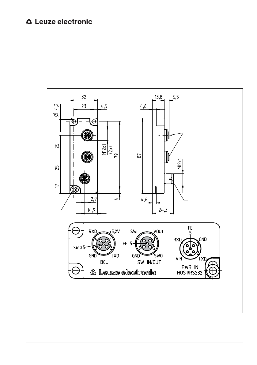
7.2 Electrical connection BPS 8
7.2.1 BPS 8 - PWR IN - Voltage supply, RS 232, Switching input/output
PWR IN (5-pin connector, A-coded)
Pin Name Comment
RXD GND
SWIN/SWOUT
VIN
3
4
5
21
PWR IN
Figure 7.1: BPS 8 - Pin assignment PWR IN
The switching input/switching output are programmed via the parameters in the configuration software BPS Configuration Tool in the tabs Switching input and Switching output. For
more information see also Chapter 8.5.4 and Chapter 8.5.5, Page 80 et seq.
CAUTION
Degree of protection IP 67!
Degree of protection IP 67 is achieved only if the connectors and caps are screwed into
place!
1 VIN Positive supply voltage: +4.9 … +5.4V DC
2 TXD RS 232 transmission line
3 GND Supply voltage: 0V DC
TXD
4 RXD RS 232 receiving line
SWIN/
5
SWOUT
Configurable switching input/output
Thread FE Functional earth (housing)
Leuze electronic BPS 8 49
TNT 35/7-24V
Page 51

Electrical connection
Connecting the functional earth FE
CAUTION
Connect functional earth!
Ensure that the functional earth (FE) is connected correctly.
Fault-free operation is only guaranteed if the functional earth is connected properly.
• BPS 8 with cable (option) and open cable end:
- Use shielded cables (see chapter 12.5 "Accessories – Cables").
- Connect the shield in the switch cabinet to FE (functional earth).
- The BPS 8 is usually connected to an earthed steel structure (PE). To prevent com-
pensating currents, FE and PE must be configured for potential equalization.
• BPS 8 connected via MA 8…:
- Use shielded cables (see chapter 12.5 "Accessories – Cables").
- Connect PIN 5 of MA 8 PWR connection cable to FE.
- The BPS 8 is usually connected to an earthed steel structure (PE). To prevent com-
pensating currents, FE and PE must be configured for potential equalization.
Cable lengths and shielding
The following maximum cable lengths and shielding types must be observed:
Connection Interface Max. cable length Shielding
BPS 8 - Service RS 232 10 m Absolutely required,
BPS 8/MA 8… - Host RS 485 25 m Absolutely required, shielded
Switching input 10 m Not necessary
Switching output 10 m Not necessary
sheath of a shielded line
Leuze electronic BPS 8 50
TNT 35/7-24V
Page 52

Electrical connection
M12 socket
(A-coded)
M12 socket
(A-coded)
M12 con-
nector
Switching input
Switching out-
7.3 Electrical connection via connection unit MA 8.1
7.3.1 Electrical connection MA 8.1
Figure 7.2: Electrical connection MA 8.1
Leuze electronic BPS 8 51
TNT 35/7-24V
Page 53

Electrical connection
3
21
4
5
RXD GND
VIN
FE
TXD
PWR IN
HOST/RS232
M12 connector
(A-coded)
7.3.2 PWR IN HOST/RS 232 connector – voltage supply and RS 232
PWR IN HOST/RS 232 (5-pin connector, A-coded)
Pin Name Comment
1VINPositive supply voltage: +10 … +30VDC
2TXD
3GNDSupply voltage: 0V DC
4RXD
5FEFunctional earth
Thread FE Functional earth (housing)
Figure 7.3: MA 8.1 – Pin assignment PWR IN HOST/RS 232 connector
CAUTION
Degree of protection IP 67!
Degree of protection IP 67 is achieved only if the connectors and caps are screwed into
place!
RS 232 transmit data from the BPS 8 to the
host
RS 232 received data from the host to the
BPS 8
Leuze electronic BPS 8 52
TNT 35/7-24V
Page 54

Electrical connection
M12 socket
(A-coded)
7.3.3 SW IN/OUT socket – switching input and switching output
SW IN/OUT (5-pin socket, A-coded)
Pin Name Comment
SWIN VOUT
FE
GND
1
4
5
23
SWOUT
SW IN/OUT
1VOUT
2SWOUTSwitching output
3GNDGND for the sensor system
4SWINSwitching input
5FEFunctional earth
Thread FE Functional earth (housing)
Figure 7.4: MA 8.1 – Pin assignment SW IN/OUT socket
CAUTION
Degree of protection IP 67!
Degree of protection IP 67 is achieved only if the connectors and caps are screwed into
place!
The switching input/switching output are programmed via the BPS Configuration Tool
configuration software. For further information, see Chapter 8.2, Page 62 et seq.
Voltage supply for sensor system (VOUT
identical to VIN at PWR IN)
CAUTION
Connecting a sensor with standard M12 connectors!
If you use a sensor with a standard M 12 connector, please note the following:
Use only sensors on which the switching output does not lie on pin 2 or sensor
cables on which pin 2 is not assigned. Otherwise, the switching output is not pro-
tected against feedback on the switching input. If the inverted sensor output lies on
pin 2, erroneous behavior of the switching output will result.
Leuze electronic BPS 8 53
TNT 35/7-24V
Page 55

Electrical connection
Switching input
Switching output
Connecting the switching input / switching output
The MA 8.1 is provided with a switching input and a switching output. The connection of
switching input / switching output is carried out in accordance with Figure 7.5.
Figure 7.5: Connection of the switching input/output of the MA 8.1
Leuze electronic BPS 8 54
TNT 35/7-24V
Page 56

7.3.4 BCL socket – connecting the BPS 8 to the MA 8.1
M12 socket
(A-coded)
BCL (5-pin socket, A-coded)
RXD VIN
SWIN/SWOUT
GND
1
4
5
23
BCL
Figure 7.6: MA 8.1 – Pin assignment BCL socket
CAUTION
Degree of protection IP 67!
Degree of protection IP 67 is achieved only if the connectors and caps are screwed into
place!
The BPS 8 is connected to the MA 8.1 via the KDS S-M12-5A-M12-5x-P1-xxx interconnection cable. The voltage supply is connected via the PWR IN HOST/RS 232 socket.
Pin Name Comment
1VIN
Supply voltage for BPS 8
+4.9 … +5.4VDC
2 TXD RS 232 transmission line
TXD
3 GND Supply voltage: 0V DC
4 RXD RS 232 receiving line
SWIN/
5
SWOUT
Programmable switching input/output of the
BPS 8
Thread FE Functional earth (housing)
Electrical connection
CAUTION
Connect functional earth!
Ensure that the functional earth (FE) is connected correctly.
Fault-free operation is only guaranteed if the functional earth is connected properly.
Leuze electronic BPS 8 55
TNT 35/7-24V
Page 57

Electrical connection
M12 connector
(A-coded)
7.4 Electrical connection via connection unit MA 8-01 / MA 8-02
Electrical data
Service interface No MA 8-01/MA 8-02 connected:
Switching input/output 1 switching input, 1 switching output, each is programmable
Operating voltage 10 … 30VDC
Power consumption Max. 0.5 W (without BPS 8)
7.4.1 PWR IN HOST/RS485 connector – voltage supply/RS 485
RS485A GND
4
5
FE
VIN
PWR IN
HOST/RS485
Figure 7.7: MA 8-01/MA 8-02 – Pin assignment PWR IN HOST/RS485 connector
RS 232 with default data format,
9.6kBit/s, 8 data bits, no parity, 1 stop bit
With MA 8-01/MA 8-02 connected:
RS 485 replaces RS 232
Switching input: 10 … 30VDC
Switching output: I
= 60mA
max
output voltage = operating voltage
PWR IN HOST/RS485 (5-pin connector, A-coded)
Pin Name Comment
1VINPositive supply voltage: +10 … +30VDC
3
21
RS485B
2 RS485B
3GNDSupply voltage: 0V DC
4 RS485A
RS 485 receive/transmit data
B-line
RS 485 receive/transmit data
A-line
5FEFunctional earth
Thread FE Functional earth (housing)
CAUTION
Degree of protection IP 67!
Degree of protection IP 67 is achieved only if the connectors and caps are screwed into
place!
Leuze electronic BPS 8 56
TNT 35/7-24V
Page 58

Electrical connection
M12 socket
(A-coded)
7.4.2 SW IN/OUT socket – switching input and switching output
SW IN/OUT (5-pin socket, A-coded)
Pin Name Comment
SWIN VOUT
FE
GND
1
4
5
23
SWOUT
SW IN/OUT
1VOUT
2SWOUTSwitching output
3GNDGND for the sensor system
4SWINSwitching input
5FEFunctional earth
Thread FE Functional earth (housing)
Figure 7.8: MA 8-01/MA 8-02 – Pin assignment SW IN/OUT socket
CAUTION
Degree of protection IP 67!
Degree of protection IP 67 is achieved only if the connectors and caps are screwed into
place!
The switching input/switching output are programmed via the parameters in the BPS
Configuration Tool configuration software. For further information, see Chapter 8.2,
Page 62 et seq.
Voltage supply for sensor system (VOUT
identical to VIN at PWR IN)
CAUTION
Connecting a sensor with standard M12 connectors!
If you use a sensor with a standard M 12 connector, please note the following:
Use only sensors on which the switching output does not lie on pin 2 or sensor
cables on which pin 2 is not assigned. Otherwise, the switching output is not pro-
tected against feedback on the switching input. If the inverted sensor output lies on
pin 2, erroneous behavior of the switching output will result.
Leuze electronic BPS 8 57
TNT 35/7-24V
Page 59

Figure 7.9: Electrical connection MA 8-01/MA 8-02
Switching input
Switching output
Electrical connection
Leuze electronic BPS 8 58
TNT 35/7-24V
Page 60

Electrical connection
M12 socket
(A-coded)
7.4.3 BCL/BPS socket – connecting the BPS 8 to the MA 8-01/MA 8-02
BCL/BPS (5-pin socket, A-coded)
RXD VIN
SWIN/SWOUT
GND
1
4
5
23
BCL / BPS
Figure 7.10: MA 8-01/MA 8-02 – Pin assignment BCL/BPS socket
CAUTION
Degree of protection IP 67!
Degree of protection IP 67 is achieved only if the connectors and caps are screwed into
place!
The BPS 8 is connected to the MA 8-01/MA 8-02 via the KDS S-M12-5A-M12-5x-P1-xxx
interconnection cable. The voltage supply is connected via the PWR IN HOST/RS485
socket.
Pin Name Comment
1VIN
Supply voltage for BPS 8
aprox. +5.2VDC
2 TXD RS 232 transmission line
TXD
3 GND Supply voltage: 0V DC
4 RXD RS 232 receiving line
SWIN/
5
SWOUT
Programmable switching input/output of the
BPS 8
Thread FE Functional earth (housing)
CAUTION
Connect functional earth!
Ensure that the functional earth (FE) is connected correctly.
Fault-free operation is only guaranteed if the functional earth is connected properly.
Leuze electronic BPS 8 59
TNT 35/7-24V
Page 61

7.4.4 Termination of the RS 485 interface
RS 485 receive/transmit data
A-line, PIN 4
RS 485 receive/transmit data
B-line, PIN 2
Permanently installed termination networks are present in the MA 8-01 and the MA 8-02
which differ in terms of resistance values. The resistor network terminates the outgoing
RS 485 data interface, as shown in Figure 7.11, and cannot be switched off.
+5.2 V
Electrical connection
MA 8-01:
390
MA 8-01:
220
MA 8-01:
390
MA 8-02:
47 k
MA 8-02:
150
MA 8-02:
47 k
GND
RS 485 A
RS 485 B
Figure 7.11: Termination of the RS 485 interface in the MA 8-01/MA 8-02
TNT 35/7-24V
Leuze electronic BPS 8 60
Page 62

Configuration / device parameters
8 Configuration / device parameters
8.1 RS 232/RS 485 interface
8.1.1 General information
The BPS 8 system is supplied with an RS 232 interface. Using the MA 8-01 or the MA 8-02
permits this to be replaced by an RS 485 interface. All settings regarding the protocols and
device parameters may be individually configured using the BPS Configuration Tool software.
The current version of the BPS Configuration Tool can be downloaded from the Leuze home
page at www.leuze.com.
Detailed information on the electrical connection can be found in Chapter 7 "Electrical
connection" on page 48.
Leuze electronic BPS 8 61
TNT 35/7-24V
Page 63

Configuration / device parameters
8.2 BPS Configuration Tool software
8.2.1 Installation of the BPS Configuration Tool software
Download the installation software to your PC:
www.leuze.com >Products >Measuring Sensors >Sensors for Positioning >Bar
Code Positioning Systems > BPS 8 > (Name of the BPS 8) > Tab Downloads
> Software/Driver> BPS-Config V Configuration Software… .
Unzip the compressed folder
Call up the installation file (…-Setup.exe)
Select the language for your installation and accept the license agreement.
Figure 8.1: Installation directory selection
Select the target folder for the installation and the components to be installed in the sub-
sequent window.
Figure 8.2: Selection of the components to be installed
Leuze electronic BPS 8 62
TNT 35/7-24V
Page 64

Configuration / device parameters
Confirm your entry with Next and follow the installation routine.
For further details please refer to online help of the "BPS Configuration Tool" software.
Start the BPS Configuration Tool by clicking on the start menu entry or by double-
clicking on the desktop icon.
8.2.2 Brief manual for the BPS Configuration Tool
General information
The BPS Configuration Tool program was developed as a convenient user-friendly tool to
operate Leuze BPS systems.
To install the tool, double click on the Setup.exe file and follow the instructions. After the
program has been successfully installed and started, the left side shows the default project
Leuze electronic. In this project, every possible device has already been created.
This project is read-only but can be edited arbitrarily and saved under a different name using
the Project -> Save as menu.
Creating a new project
Select Project -> New… or click on the symbol in the top left corner.
Assign a file name. Up to 256 characters are possible.
The .PCT extension must remain the same.
Assign a project name (= title) to the project. Up to 256 characters are possible.
Enter a description if required.
After confirmation with OK, the new project name is shown in the top left corner.
Create individual devices
Left click on project name (= title)
Device -> New -> Individual device or click on the top left icon .
Assign a device name
Select device type (only BPS can be selected).
Select BPS type
Select BPS version = software version of the device
After clicking OK, the new device is shown in the project.
Follow this procedure to create all devices required.
When creating an individual device, the Leuze standard parameter set is always created
together with the selected device according to the software version selected. The interface
data from the PC to the device are also created together with the Leuze standard settings.
These are:
• Data format: 9600 / 8 / 1 / None
• Framing protocol: <STX><data><CR><LF>
• Address: none
Leuze electronic BPS 8 63
TNT 35/7-24V
Page 65

Configuration / device parameters
Display erroneous parameters
Display changed parameters
Display all parameters
Close all parameters
Copying and pasting devices
It is possible to copy and paste individual devices. To do this, the device to be copied must
be selected. By clicking on the right mouse button, the Copy and Paste functions become
available. Only the device settings are copied, not the deposited interface data of the PC.
Renaming devices
It is possible to rename individual devices. This requires the respective device to be
selected. Right click on the mouse button, select Device properties… and enter the desired
description under Name.
Graphical configuration
If a device is selected via the left mouse button, the window of the graphical configuration
opens automatically. The graphical interface visualizes the device settings and these can be
loaded or transferred using the symbols and .
For further help on device-specific parameters, the technical description for the selected
device may be opened. To view the technical description of the device, click on the
symbol.
All parameters that were changed, i.e. that deviate from the Leuze factory settings, have a
yellow background or frame color or are marked with the symbol for better orientation.
To reset all parameters of the selected device back to the Leuze factory settings, click on
the symbol. This only resets the values in the PC and not the settings in the BPS.
Tree structure configuration
The second option for working off-line is the tree structure. The tree structure contains all
settings of the graphical structure plus additional parameters.
Terminal
The third option of communicating with the device is the terminal. This is only possible
online.
Leuze electronic BPS 8 64
TNT 35/7-24V
Page 66

Configuration / device parameters
Sets all parameters in the device to the factory settings!
Software reset
Version query
Displays the measurement values on the terminal
Does not display the measurement values on the terminal
Starts the measurement process
Ends the measurement process
If no device is selected, only the terminal is available. Its interface settings are available
under Options -> Communication…. They can also be selected by clicking on the commu-
nication parameters displayed in the lower status bar.
Standard commands
The right third of the terminal window shows the following symbols for direct online
commands:
NOTE
Switching between online and offline configuration!
Please note that the device settings are not always displayed with their current values
if one changes between online and offline configuration.
If a parameter is edited using an online command, the change is only displayed in the
graphical menu (and thus stored in the project) once the edited parameters have been
uploaded from the device!
Leuze electronic BPS 8 65
TNT 35/7-24V
Page 67

Configuration / device parameters
Terminal options
From the menu, select Terminal -> Options… or click on the symbol (terminal must be
selected). From the Send and Receive tabs choose between the 3 data formats ASCII,
Hexadecimal and Decimal. Standard: ASCII
If your computer has the Terminal font installed, please select this font for the display.
In the Terminal tab you also have the option to output the Line number, the Date and the
Time.
Terminal content
Use the , , and symbols to save, open or print the data in the terminal window.
Use to clear the content of the terminal window.
In Version V01.12 and higher of the BPS Configuration Tool, the terminal content is
logged automatically in the file terminal.txt. This file is stored in the main directory of the
BPS Configuration Tool. It may be edited with any text editor.
NOTE
If another device is selected, the file content is deleted and the recording starts again.
User-defined commands
By using the symbol, you can create your own commands or sequences or load previously stored commands. In the window that appears, the following labels mean:
Command name: description of the symbol's command.
Command: actual command sequence.
Click the Accept button and the new commands appear in the right third of the terminal
window below the permanently defined symbols.
Send file
This feature has been implemented to permit several consecutive sequences to be transmitted to the device. This requires the sequences to be created as a text file first. The text
file can then be retrieved under Terminal -> Send file.
Boot
For the scanner families BPS 8 and BPS 3x, the firmware may be changed directly with the
BPS Configuration Tool. This requires the respective firmware boot file, however. To obtain
the file, please get in touch with your respective contact person.
Graphical measurement value monitoring
This view allows the current position of the BPS system to be graphically displayed.
Leuze electronic BPS 8 66
TNT 35/7-24V
Page 68

Setting the device-specific interface values
This sets the connection (interface) from the PC to the device and not the interface of the
device. For service interface operation, the settings here do not need to be edited.
If the connected device is not operated via the service protocol:
Use the left mouse button to select the device to be edited.
Right click and select Communication. In the Communication properties window that
opens, carry out the respective changes.
If the settings were changed, the Leuze standard parameters can be reselected by clicking
on the button.
MA 8-01/MA 8-02 connection unit
The MA 8-01/MA 8-02 connection unit is not relevant for the configuration and is thus not
explicitly supported in the BPS Configuration Tool.
8.2.3 Setting the parameters
You now have commissioned the BPS 8 and are ready to configure it. Using the parameter
options made available by the BPS 8, you can configure the BPS 8 to suit your individual
area of application. For instructions regarding the various setting options, refer to the online
help or to Chapter 8.5, Page 71.
The various parameter sets are explained briefly in Chapter 8.4, to understand what is
happening during parameter setting. The setting of the parameters then takes place in the
service operating mode, which is described in the following chapter.
Configuration / device parameters
Leuze electronic BPS 8 67
TNT 35/7-24V
Page 69

8.3 Service operating mode
Setting the required parameters is carried out in the Service operating mode. The operating
mode Service provides the following defined operating parameters on the external RS232
interface, no matter how the BPS 8 is configured for standard operation:
• Transmission rate: 9.6 kBit/s
•No parity
• 8 data bits
• 1 stop bit
•Prefix: STX
• Postfix: CR, LF
8.3.1 Activate service interface
The service interface may be activated as follows:
•Via a "v" command during power-up (initialization phase).
• Via the SRV control bar code (see accompanying package insert) in front of the reading window during power-up (initialization phase)
Configuration / device parameters
Figure 8.3: SRV control bar code
8.3.2 Connecting the service interface
You can connect a PC or a terminal to the BPS 8 via the serial interface and configure the
BPS 8 through this connection. For this, you need a crossed RS 232 interconnection cable
(null modem cable) that provides the connections RxD, TxD and GND. A hardware handshake via RTS, CTS is not supported at the service interface.
Leuze electronic BPS 8 68
TNT 35/7-24V
Page 70

Configuration / device parameters
3 GND
2 TxD
4 RxD
BPS 8
PC
Shield
Figure 8.4: Connecting the RS 232 service interface to a PC or terminal
8.3.3 Overview of commands and parameters
Online commands can be used to send commands directly to the BPS 8 for control and
configuration.
For this, the BPS 8 has to be connected to a host or service computer via the serial interface.
The commands described can be sent either via the host or the service interface.
General online commands
Command Description
M+ Activation of the measurement.
M- Deactivation of the measurement.
MMS
MMTyyyy
MM-
PC20 Resets all parameters in the BPS 8 to Leuze default values.
V
Controls the data output via the service interface.
A single measurement value is output (Single Shot mode).
Controls the data output via the service interface.
Measurement values are output cyclically; time must be subsequently
specified:
yyyy = Time specification in ms.
Example: MMT0500.
Measurement values are output via the service interface in a
time interval of 500ms.
Deactivation of the MMTyyy function.
If the cyclical output via the service interface is no longer required, the
function must be deactivated using the command MM-.
Version query, or puts the device into service mode.
This requires a "V" to be transmitted during the initialization phase of the
BPS 8.
TNT 35/7-24V
Leuze electronic BPS 8 69
Page 71

Configuration / device parameters
8.4 Overview of the parameter structure
Using the BPS Configuration Tool program, parameters can be changed via the service
interface. These parameters are separated into individual tabs in the Graphical configura-
tion menu.
The following tabs are available:
Tab name Folder contents
Control
Page 7 2
Position detection
Page 7 3
Communication
Page 7 8
Switching input
Page 8 0
Switching output
Page 8 2
• Measurement start mode
• Measurement stop mode
• Maximum polling interval
• Resolution for the position value
• Integration time
• Preset value added to tape value
• Counting direction for position calculation
• Scaling factor
• Offset value
• Maximum permitted measurement length
• Minimum permitted measurement length
• Position tolerance time
• Error output delay
• Baud rate
• Data mode
•Protocol
• Address
• Inversion
• Mode
• Debounce time
• Start-up delay
• Pulse duration
• Switch-off delay
• Function
• Activation
• Deactivation
• Pulse duration
TNT 35/7-24V
Leuze electronic BPS 8 70
Page 72

8.5 Detailed description of the tabs
aza
h
NOTE
Note cross-references to parameters!
In the following detailed descriptions of the tabs you will find in the last column of the tables
cross references (CR) to parameters and input/output data of other tabs which are
directly related to the described parameter.
Pay attention to these cross-references during configuration.
Within the tabs, the parameters are labeled alphanumerically from ... .
Example:
The parameter Preset value static [mm] is activated only if the preset teaching is carried
out via switching input .
Configuration / device parameters
TNT 35/7-24V
Leuze electronic BPS 8 71
Page 73

8.5.1 Control
a
h
b
h
c
Figure 8.5: Control tab
Description:
The control manages the timing of the position calculation by starting and stopping the
decoding. Control is performed depending on certain events such as the switching input or
time functions. Using parameters, the events which influence the states are determined.
Parameters
Configuration / device parameters
Parameter Description Value ra nge Default Unit CR
Start mode
Stop mode
Maximum
polling
interval
The start mode determines by
which event the position measurement is started.
The stop mode determines after
which event the position measurement is stopped.
Time period after which the
scanning beam is switched off if
no polling takes place.
1: After initialization
2: Via command or
switching input
2: Time (Polling Interval)
3: Time with re-trigger-
ing function (polling
interval) via command or switching
input
4: Via command or switch-
ing input (the switching
input must be programmed for this purpose)
0…65,535 10,000 ms
2 –
3 –
Switching
input
Switching
input
TNT 35/7-24V
Leuze electronic BPS 8 72
Page 74

8.5.2 Position detection
a
Configuration / device parameters
Figure 8.6: Position detection tab
Description:
The position detection controls all settings that affect the position values.
Resolution parameter
Parameter Description Value ra nge Default Unit CR
The parameter specifies the
resolution for the position value.
Resolution
in [mm]
The resolution has no effect on
- Static preset
- Offset.
1: 0.01
2: 0.1
3: 1
4: 10
5: 100
6: 1,000
3 mm –
TNT 35/7-24V
With the Resolution parameter, the resolution for the position values is defined. This parameter also performs a rounding correction (the position value is divided by the defined value
range).
The resolution only determines the mathematical decimal value and has no effect on the
measurement accuracy.
Leuze electronic BPS 8 73
Page 75

Configuration / device parameters
b
Maximum position value which can be represented
The binary protocols 1 to 6 convey the position value with a different number of data bits.
The number of data bits and the selected resolution determine the maximum position value
that can be represented.
Maximum position value which can be represented with a resolution of
1mm (default) 0.1mm 0.01mm 0.001 mm
Binary protocol 1, 4, 6
(32 data bits)
Binary protocol 2
(24 data bits)
Binary protocol 3
(21 data bits)
1) The maximum position value that can be presented is limited by the maximum length of
the bar code tape.
Integration depth parameter
10,000,000
1)
mm
10,000,000mm
2,097,152mm 209,715mm 20,971mm 2,097 mm
10,000,000mm
1)
1,677,721mm 167,772mm 16,777mm
1)
10,000,000mm1)4,294,967mm
Parameter Description Value ra nge Default Unit CR
Integration
time
Number of consecutive scans
which are to be used for position
determination.
4…32 8
Integra-
tion
steps
–
The integration depth parameter is used to specify the number of raw position data which is
used for integration in order to determine the position value.
Integration depth Integration time [ms]
4 13.2
5 16.5
6 19.8
7 23.1
8 (default) 26.4
9 29.7
10 33.0
::
29 95.7
30 99.0
31 102.3
32 105.6
In order to obtain more exact measurement data while in the static state or for very slow
travel speeds, the integration depth can be increased here. If, however, a high integration
depth is used for high speeds, the contouring error is increased. With respect to contouring
errors and exact measurement data, very good results have been obtained using 8 integration steps. Using 8 integration steps, the integration time is 26.4ms.
TNT 35/7-24V
Leuze electronic BPS 8 74
Page 76

Configuration / device parameters
cdehf
Counting direction "normal"
Counting direction "inverted"
Position value = tape value
Position value
Counting direction
Counting direction
1,400,000 mm
8,600,000mm (=10,000,000mm - tape value)
0 mm 10,000,000 mm
0 mm 10,000,000 mm
Preset parameter
Parameter Description Value ra nge Default Unit CR
Preset
mode
Memory
mode
Preset value
in [mm]
Switches the preset function on
or off
Store data temporarily or permanently.
New position value after teach
event.
With this parameter, a preset value can be defined which the BPS 8 outputs following a
teach event. A switching input function is defined as a teach event. After reading in the
preset, the current position value is replaced by the preset value and the position value is
now calculated and output on the basis of the preset. The preset remains stored in the
BPS 8 and remains active even following a new start. In order for the BPS 8 to again output
the position value without the preset, the Preset mode must be switched off again.
Counting direction parameter
To activate this function, the preset mode must be switched on.
The preset value is always entered in units of mm, independent of the resolution setting.
The scaling factor has no effect on the static preset value.
Parameter Description Value ra nge Default Unit CR
Counting
direction
Counting direction for position calculation.
The BPS 8 is set as follows by default:
The position value is output with normal counting direction. With the inverted counting
direction, 10,000,000mm minus the position value is output. The Preset value and Offset
value parameters can be used to influence this behavior.
1: Off
2: On
1: Permanently
2: Temporarily
0 … 10,000,000 0 mm
0: Normal
1: Inverted
1 ––
1 ––
0 ––
Switching
input
Figure 8.7: Counting direction for position calculation
Leuze electronic BPS 8 75
TNT 35/7-24V
Page 77

Configuration / device parameters
ghidejd
e
Scaling factor parameter
Parameter Description Value ra nge Default Unit CR
Scaling factor in [‰]
Scaling factor used to convert
the position values.
The scaling function is used to convert the tape values to any unit of measurement. To do
this, the tape value is multiplied by the scaling factor.
This parameter affects the Offset value. The Preset value parameter is not influenced by the
scaling.
Offset value parameter
Parameter Description Value ra nge Default Unit CR
Offset value
in [mm]
Offset value added to tape
value.
This function adds an offset value to the tape value.
If the Preset parameter is activated and, as a result, a new value assigned to the tape value,
the Offset function no longer affects the position value. The offset is not reactivated until the
preset function is canceled. The offset value is entered in mm. When entering the offset
value, the scaling factor parameter must be taken into account.
Min./max. measurement length parameter
Parameter Description Valu e r an ge Default Unit CR
Min. measurement
length in
[mm]
Max. measurement
length in
[mm]
Minimum permitted measurement length.
Maximum permitted measurement length.
With this parameter, a working limit on the bar code tape can be defined. The BPS 8 outputs
position values within these minimum and maximum limits. Outside of this limit, a position
value of zero is output.
The switching output can be used to indicate that the measured value is outside of the
measurement range. To enable this function, the "outside measurement range" or "inside
measurement range" parameter must be activated.
0…65,535 1,000 ‰–
-10,000,000 … 10,000,000 0 mm –
Switching out-
0 … 2,147,483,647 0 mm
0 … 2,147,483,647 10,000,000 mm
put
,
Switching out-
put
,
TNT 35/7-24V
Leuze electronic BPS 8 76
Page 78

Measurement error tolerance parameter
klm
n
Configuration / device parameters
Parameter Description Valu e r an ge Default Unit CR
Tol er an ce
time in [ms]
Delayed
output of
position
error
Delayed
output of
error status
Specifies the time for the
display of the last position
value following an error.
Delays the output of an
error by the configured tolerance time.
Delays the output of an
error in the status byte of
the binary protocol by the
configured tolerance time.
0 … 65,535 50 ms –
0: No, error delay deacti-
vated
1: Yes, error delay acti-
vated
0: No, error delay deacti-
vated
1: Yes, error delay acti-
vated
1 ––
1 ––
The measurement error tolerance function is used to configure a time which results in an
extended output of the last position value in the event of an error. If the position value
changes momentarily to zero, e.g. due to a brief interruption of the scanning beam, soiling
of the bar code tape or other short-term disturbances, the BPS 8 transmits the last valid position value.
If the error disappears within the configured time, the control notices nothing. The availability
of the system is thereby ensured. No new values are delivered by the BPS 8, however, for
a period of time extending up to the configured tolerance time. With the Delay error output
parameter, an integration error (corresponds to a missing position value) can be signaled
immediately or after the tolerance time has elapsed. If the error persists after the tolerance
time has elapsed, the last valid position value is output.
Position value in the case of failure parameter
Parameter Description Value ra nge Default Unit CR
Position
value in the
case of failure
In the case of failure, retain the
last position value or output
zero.
0: Zero
1: Last valid
position value
1 ––
TNT 35/7-24V
Leuze electronic BPS 8 77
Page 79

8.5.3 Communication
a
bcd
Figure 8.8: Communication tab
Parameters
Configuration / device parameters
Parameter Description Va lu e r an ge Default Unit CR
Setting the baud
Baud rate
Data
mode
Protocol
Address
rate.
Setting of the data
mode.
Setting the protocol type.
Sets the participant address for
the RS 485 network.
4: 1200
5: 2400
6: 4800
7: 9600
8: 19200
9: 38400
10: 57600
11: 62500
12: 115200
13: 187500
1: 7 data bits, no parity, 2 stop bits
2: 7 data bits, even parity, 1 stop bit
3: 7 data bits, even parity, 2 stop bits
4: 7 data bits, odd parity, 1 stop bit
5: 7 data bits, odd parity, 2 stop bits
6: 8 data bits, no parity, 1 stop bit
7: 8 data bits, no parity, 2 stop bits
8: 8 data bits, even parity, 1 stop bit
9: 8 data bits, even parity, 2 stop bits
10: 8 data bits, odd parity, 1 stop bit
11: 8 data bits, odd parity, 2 stop bits
12: 8 data bits, no parity, 1 stop bit + WakeUp
bit
13: 9 data bits, no parity, 1 stop bit
17: Binary protocol 2
18: Binary protocol 3
19: Binary protocol 1
20: Binary protocol 4
23: Binary protocol 6
0: Address 0
1: Address 1
2: Address 2
3: Address 3
10 Baud –
6 ––
19 ––
0 ––
The 5 different binary protocols are described in a separate chapter (see chapter 9 "Protocols for position value output").
TNT 35/7-24V
Leuze electronic BPS 8 78
Page 80

Configuration / device parameters
The settings in the communication area apply to the RS 232 interface of the BPS 8 and to
the settings of the RS 485 interface of the MA 8-01/MA 8-02. The conversion from RS 232
to RS 485 in the MA 8-01 is implemented entirely in hardware. The communication
settings for the RS 232 interface also apply to the RS 485 for this reason.
Leuze electronic BPS 8 79
TNT 35/7-24V
Page 81

8.5.4 Switching input
Figure 8.9: Switching input tab
Description:
Within this tab, the mode of operation of the digital switching input is defined.
Configuration / device parameters
Leuze electronic BPS 8 80
TNT 35/7-24V
Page 82

Parameters
abcdefghe
a
b
Configuration / device parameters
Parameter Description Value ra nge Default Unit CR
Defines whether the switching
input and output are activated
Digital
I/O mode
Inversion
Mode
Debounce
time in [ms]
Start-up
delay in
[ms]
Pulse duration in [ms]
Switch-off
delay in
[ms]
Function
via the MA 8-01/MA 8-02 or
whether only the switching input
or only the switching output is
activated.
The parameter defines the logic
of the applied signal. In case of
an inversion, an external HIGH
level is interpreted as an internal LOW level.
This parameter controls the
release of the switching input.
This parameter defines a
debounce time which is implemented via software.
The parameter influences the
timing during switch-on.
The parameter defines a minimum time period before the signal is reset.
The parameter defines a time
delay for the signal during
switch-off.
The parameter specifies the
function which is to be activated
or deactivated by a status
change at the switching input.
0: Not released
1: BPS 8 with MA 8-01/
MA 8-02 (switching
input + switching
output)
2: Switching input
3: Switching output
0: No (active high)
1: Yes (active low)
0: Off
1: On
0…255 5 ms –
0 … 65535 0 ms –
0 … 65535 0 ms –
0 … 65535 0 ms –
0: No function
1: Teach preset
2: Start/stop position
measurement
3: Stop position mea-
surement
1 ––
0 ––
1 ––
Pos itio n
detection
2 –
–
Control
Control
The switching input function Pos. measurement start/stop in the Function parameter
means:
TNT 35/7-24V
• High level at the switching input starts the position measurement.
• Low level at the switching input stops the position measurement.
Leuze electronic BPS 8 81
Page 83

8.5.5 Switching output
Configuration / device parameters
Figure 8.10: Switching output tab
Description:
Within this tab, the mode of operation of the digital switching output is defined.
Leuze electronic BPS 8 82
TNT 35/7-24V
Page 84

Parameters
a
b
c
dijij
e
i
j
i
j
Configuration / device parameters
Parameter Description Value ra nge Default Unit CR
Defines whether the switching
input and output are activated
Digital
I/O mode
Bias level /
inverted
Pulse duration in [ms]
Switch-on
function
[EF]
Switch-off
function
[AF]
via the MA 8-01/MA 8-02 or
whether only the switching input
or only the switching output is
activated.
The parameter defines the bias
level of the switching output.
The parameter defines the
switch-on time period for the
switching output. If the value is
0, the signal is static.
The parameter specifies the
events which set the switching
output:
- outside measurement range 0
- within measurement range 0
- erroneous measurement 1
- successful measurement 0
The parameter specifies the
events which reset the switching
output:
- outside measurement range 0
- within measurement range 0
- erroneous measurement 0
- successful measurement 1
0: Not released
1: BPS 8 with MA 8-01/
MA 8-02 (switching
input + switching
output)
2: Switching input
3: Switching output
0: LOW (0V)
1: HIGH (+Ub)
0 ... 1300 400 ms –
Each
0: Not active
1: Active
Each
0: Not active
1: Active
1 ––
0 ––
Pos itio n
detection
–
Pos itio n
detection
Pos itio n
detection
Pos itio n
detection
Pos itio n
detection
Pos itio n
–
detection
Pos itio n
detection
Pos itio n
detection
,
,
–
,
,
The events of the switch-on function and switch-off function are both linked to one another
with a logical OR.
TNT 35/7-24V
Leuze electronic BPS 8 83
Page 85

Protocols for position value output
9 Protocols for position value output
This chapter describes the five binary protocols for communication between host and BPS 8
that can be selected via the communication parameters
(see Chapter 8.5.3).
9.1 Binary protocol 1 – BPS 8 SM 10x-01 / BPS 8 SM 10x-05
With the BPS Configuration Tool, the user can individually adapt the binary protocols 1
and 6 to the specific requirements of the application. The binary protocols 2, 3 and 4, on the
other hand, have a fixed structure and cannot be modified.
9.1.1 Data format
Data format BPS 8 SM 10x-01 BPS 8 SM 10x-05
Baud rate 57.6 kBit/s 19.2 kBit/s
Number of data bits 8 8
Number of start bits 1 1
Number of stop bits 1 1
Parity None None
Addressing None None
Operating mode RS232 half duplex RS232 half duplex
Handshake None None
Table 9.1: BPS 8 SM 10x-01 / BPS 8 SM 10x-05 data format
Using the BPS Configuration Tool, the data format may be configured arbitrarily. The
default values are the values shown above.
9.1.2 Request telegram to the BPS 8 SM 10x-01 / BPS 8 SM 10x-05
The request telegram consists of two bytes.
Request telegram structure
Byte no. Designation Bit 7 Bit 6 Bit 5 Bit 4 Bit 3 Bit 2 Bit 1 Bit 0
0 Request byte 000SINGLEPOSSLEEPMD
1 XOR combination Exclusive OR combination of byte 0 with 00
(repetition of the request byte)
h
Leuze electronic BPS 8 84
TNT 35/7-24V
Page 86

Description
Protocols for position value output
Byte Bit Name Function Description
0
10XOR XOR combination Exclusive OR combination of byte 0 with 00
D Request
0
M Request
1
SLEEP Activate
2
POS Request
3
SINGLE Request
4
5…7 – None Without function, bit permanently set to 0
diagnostic information
marker data
Standby mode
position information
single measurement
1 = Request diagnostic data
0 = Do not request diagnostic data
1 = Request marker data
0 = Do not request marker data
1 = Activate Standby mode.
0 = Positioning mode
1 = Request position data
0 = Do not request position data
1 = Request single measurement (laser on, measurement, laser off)
0 = Do not request single measurement
h
Bit SINGLE: If this bit is set to 1, a single measurement is output
(laser on – measurement – laser off).
The response telegram to the "SINGLE" request is sent after around 40 ms.
The "SINGLE" request cycle must be greater than 40 ms.
Bit POS: If this bit is set to 1, the position data is output.
The "POS" request cycle must be greater than 10 ms. If the no "POS" request
occurs within 10 ms, the laser is deactivated. A response telegram is sent to
a repeat "POS" request after approx. 30 ms.
Bit SLEEP: If this bit is set to 1, the Standby mode is activated.
The polygon wheel motor and the laser are switched off in Standby. Diagnosis
of the read system cannot be performed. When the device is reactivated, the
system start-up time is approx. 5 s.
Bit M: If this bit is set to 1, the marker bar code content is output.
Bit D: If this bit is set to 1, the diagnostic data is sent in response. An indicated error
is reset once all diagnostic data has been polled. This is indicated by the status
LED changing from red to green.
It is advisable to set only one bit in the request byte, as the BPS can only answer one request
at a time. If several bits are set, the function with the highest priority is executed.
Priority of the bits in the request byte:
• Priority 1: Diagnostic data request (D)
• Priority 2: Marker data request (M)
• Priority 3: Standby request (SLEEP)
• Priority 4: Position data request (POS)
• Priority 5: Request for one-time transmission of position data (SINGLE)
Leuze electronic BPS 8 85
TNT 35/7-24V
Page 87

Protocols for position value output
9.1.3 BPS 8 SM 10x-01 / BPS 8 SM 10x-05 response telegram
The response telegram consists of 6 bytes.
Response telegram structure
Byte no. Designation Bit 7 Bit 6 Bit 5 Bit 4 Bit 3 Bit 2 Bit 1 Bit 0
0 Status byte 0 Q1 Q0 SLEEP MM D OUT ERR
1 Data byte 1 P31 P30 P29 P28 P27 P26 P25 P24
2 Data byte 2 P23 P22 P21 P20 P19 P18 P17 P16
3 Data byte 3 P15 P14 P13 P12 P11 P10 P09 P08
4 Data byte 4 P07 P06 P05 P04 P03 P02 P01 P00
5 XOR combination Bitwise exclusive OR combination of bytes 0 to 4
Description
Byte Bit Name Function Description
0
1…4
50…7XOR XOR combination Bitwise exclusive OR combination of bytes 0 to 4
ERR Internal error 1 = An internal error has occurred
0
OUT Tape error 1 = No bar code decodable
1
D Diagnostic data exist 1 = Diagnostic data are present in the memor y
2
MM Marker bar code present 1 = The content of a marker bar code is in the memory
3
SLEEP Standby state 1 = Device is in Standby mode
4
Q0 Reading quality Q1Q0 00 = Reading quality > 75%
5
Q1 10 = Reading quality 50% … 25%
6
7 – None Without function, bit permanently set to zero
0…7
Data,
P31 … P00
Data Depending on the request, the data are transferred here; either posi-
0 = No error exists
0 = Bar code decodable
0 = No diagnostic data exists
0 = No content of a marker bar code in the memory
(see request telegram)
0 = Device is in positioning mode
01 = Reading quality 75% … 50%
11 = Reading quality < 25%
tion data, diagnostic data, marker data or SLEEP response.
Position data
The position data are output in two's complement as a 32-bit signed integer value by
default in millimeters with a resolution of 1 mm (see chapter 8.5.2 "Position detection")
The P00 data bit corresponds to the LSB, the P31 data bit corresponds to the MSB.
TNT 35/7-24V
Leuze electronic BPS 8 86
Page 88

Protocols for position value output
Marker bar code
If information consisting of one of the capital letters A / B / C / D / Z and two digits is read,
the MM bit for the recognition of a marker bar code is set in the status byte:
0 = No marker data in the memory.
1 = Marker data in the memory.
The data content of the marker bar code can now be requested in the request telegram using
the request bit M. If the data content of the marker bar code is not requested, the position
continues to be output.
The marker data are output as an ASCII hex value in the data bytes 2 … 4.
Data byte 2: First marker bar code character (capital letter A, B, C, D or Z)
Data byte 3: Second marker bar code character (digit from 0…9)
Data byte 4: Third marker bar code character (digit from 0…9)
If no marker data are present in the memory of the BPS 8 and the request bit M is set, E00
is transmitted.
For more detailed information on marker bar codes, see see chapter 5.3 "Marker bar codes"
on Page 27.
Example: output of marker data
Marker bar code: A01
Data byte 2 = A = 41
Data byte 3 = 0 = 30
Data byte 4 = 1 = 31
Byte no. Designation Bit 7 Bit 6 Bit 5 Bit 4 Bit 3 Bit 2 Bit 1 Bit 0
0 Status byte 0 Q1 Q0 SLEEP MM D OUT ERR
1 Data byte 1 00000000
2 Data byte 2 01000001
3 Data byte 3 00110000
4 Data byte 4 00110001
5 XOR combination Exclusive OR combination of bytes 0 to 4
= 01000001b
h
= 00110000b
h
= 00110001b
h
Leuze electronic BPS 8 87
TNT 35/7-24V
Page 89

Protocols for position value output
Marker bar code in the detection range
• The respective MM bit in the status byte is set.
• Marker data are stored in the memory.
• Marker data can only be overwritten by new marker data.
• The memory is deleted:
• after power off/on.
• in Standby mode.
• if no polling takes place for 10s.
Marker data
are retrieved.
Marker data are not
retrieved.
New or old
marker bar code is
detected.
• Marker data are retrieved by the request telegram.
• Marker data are deleted from the memory.
• The respective MM bit in the status byte is reset once the
memory no longer contains any data.
New or old marker bar code is detected.
Function sequence when a marker bar code is in the detection area:
Figure 9.1: Function sequence for marker bar code inside the detection area
Leuze electronic BPS 8 88
TNT 35/7-24V
Page 90

Protocols for position value output
No marker bar code in the detection range
• The respective MM bit in the status byte remains set until the
marker data have been retrieved.
• Marker data are deleted after they have been
read.
Marker data
are retrieved.
Marker data
are not retrieved.
• Marker data are retrieved by the request telegram.
• Marker data are deleted from the memory.
• The respective MM bit in the status byte is reset and remains
reset until another marker bar code is detected.
New or old marker bar code is detected.
This process toggles the data as long as the MM bit is set to 1, and the memory contains
marker data. The MM status information does not depend on the BPS' speed or on the
control's clock rate.
Figure 9.2: Function sequence for no marker bar code inside the detection area
Leuze electronic BPS 8 89
TNT 35/7-24V
Page 91

Protocols for position value output
Diagnostic data
If the diagnostic bit D in the status byte is set to 1, diagnostic data is present and may be
retrieved.
The diagnostic data are retrieved by setting the bit D (bit 0) in the request byte. The diagnostic bit D remains set to 1 as long as data are present. Only after the memory for diagnostic data is empty, the bit changes to 0 and the red status LED returns to normal mode.
Like the marker data, the diagnostic data are output as an ASCII hex value in the data bytes
2…4.
Data byte 2: First diagnostic data character
Data byte 3: Second diagnostic data character
Data byte 4: Third diagnostic data character
Possible diagnostic data:
E01 = interface problem
E02 = motor problem
E03 = laser problem
E04 = internal problem
E05 = position value outside of measurement range
E09 = invalid control bar code
If bit 2 SLEEP is set to 1 in the request byte and in the status byte bit 2 D has the value 1,
BPS 8 is in Standby mode (SLEEP – laser and polygon wheel motor off). If bit 2 SLEEP in
the control byte is set to 0, the BPS 8 returns to positioning mode after a boot time of approx.
5s. If polling takes place while the BPS 8 boots and there is no valid position data yet, the
error message No decodable bar code (bit OUT) is generated.
Example: output of diagnostic data
Diagnostic data: E05
Data byte 2 = E = 45
Data byte 3 = 0 = 30
Data byte 4 = 5 = 35
Byte no. Designation Bit 7 Bit 6 Bit 5 Bit 4 Bit 3 Bit 2 Bit 1 Bit 0
0 Status byte 0 Q1 Q0 SLEEP MM D OUT ERR
1 Data byte 1 00000000
2 Data byte 2 01000101
3 Data byte 3 00110000
4 Data byte 4 00110101
5 XOR combination Exclusive OR combination of bytes 0 to 4
= 01000101b
h
= 00110000b
h
= 00110101b
h
Leuze electronic BPS 8 90
TNT 35/7-24V
Page 92

Protocols for position value output
9.2 Binary protocol 2 – BPS 8 SM 10x-02
With the BPS Configuration Tool, the user can individually adapt the binary protocols 1
and 6 to the specific requirements of the application. The binary protocols 2, 3 and 4, on the
other hand, have a fixed structure and cannot be modified.
9.2.1 Data format
Data format BPS 8 SM 10x-02
Baud rate 62.5 kBit/s
Number of data bits 9
Number of start bits 1
Number of stop bits 1
Parity None
Addressing 0 … 3
Operating mode RS232 half duplex
Handshake None
Table 9.2: BPS 8 SM 10x-02 data format
9.2.2 Request telegram to the BPS 8 SM 10x-02
The request telegram consists of one byte.
Request telegram structure
Byte no. Designation Bit 8 Bit 7 Bit 6 Bit 5 Bit 4 Bit 3 Bit 2 Bit 1 Bit 0
0 Request byte 1011S2S1S0A1A0
Description
Byte Bit Name Function Description
0
A0 Address A1A0 in
0
A1 10 = Address 2
1
S0 Coded data request through
2
S1 0 0 0 Request position data
3
S2 0 1 0 Request diagnostic data
4
5 – None Without function, bit permanently set to 1
6 – None Without function, bit permanently set to 1
7 – None Without function, bit permanently set to 0
8 – None Without function, bit permanently set to 1
RS 485 network
the 3 bits S2, S1, S0
00 = Address 0
01 = Address 1
11 = Address 3
Coded request
S2 S1 S0 Meaning
0 0 1 Request marker data
1 0 0 Request one-time position data transfer
A0 and A1 are the address bits. If several BPS 8 operate in an RS485 network, an address
configuration is required. Every BPS 8 is supplied with the Standard address 0. The
Leuze electronic BPS 8 91
TNT 35/7-24V
Page 93

Protocols for position value output
address assignment (Default: 0) is performed using the BPS Configuration Tool (see
chapter 8.5.3 "Communication").
NOTE
RS485 network!
An MA 8-01/MA 8-02 connection unit is mandatory for the operation of the BPS 8 in an
RS485 network (see chapter 4.2 "MA 8-01 / MA 8-02 connection unit").
Bits S2, S1, S0: If all bits are set to 0, the position data are output.
The position data request cycle must be greater than 10 ms. If no position
data request occurs within 10 s, the laser is deactivated. A response telegram is sent to a repeat position data request after approx. 30 ms.
If only the S0 bit is set to 1, the marker data are output.
If only the S1 bit is set to 1, the diagnostic data are sent in response. An
indicated error is reset once all diagnostic data has been polled. This is
indicated by the status LED changing from red to green.
If only the S2 bit is set to 1, position data are output once (laser on –
measurement – laser off).
The response telegram to the single measurement request is sent after
around 40 ms. The single measurement request cycle must be greater
than 40 ms.
Only ever one of the S2, S1, S0 bits should be set in the request byte, because the BPS can
only respond to one request. If several bits are set, the function with the highest priority is
executed.
Priority of the bits in the request byte:
• Priority 1: Diagnostic data request
• Priority 2: Marker data request
• Priority 3: Request for one-time transmission of position data
• Priority 4: Position data request
Leuze electronic BPS 8 92
TNT 35/7-24V
Page 94

9.2.3 BPS 8 SM 10x-02 response telegram
The response telegram consists of 8 bytes.
Response telegram structure
Byte no. Designation Bit 8 Bit 7 Bit 6 Bit 5 Bit 4 Bit 3 Bit 2 Bit 1 Bit 0
0 Status byte 0 D M A1 A0 QT1 QT0 OUT ERR
1 Data byte 1 0 P23 P22 P21 P20 P19 P18 P17 P16
2 Data byte 2 0 P15 P14 P13 P12 P11 P10 P09 P08
3 Data byte 3 0 P07 P06 P05 P04 P03 P02 P01 P00
4 XOR combination Bitwise exclusive OR combination of bytes 0 to 3
5 Repetition of data byte 1 0 P23 P22 P21 P20 P19 P18 P17 P16
6 Repetition of data byte 2 0 P15 P14 P13 P12 P11 P10 P09 P08
7 Repetition of data byte 3 0 P07 P06 P05 P04 P03 P02 P01 P00
Description
Protocols for position value output
Byte Bit Name Function Description
0
1…3
40…8XOR XOR combination Bitwise exclusive OR combination of bytes 0 to 3
5…7
ERR Internal error 1 = An internal error has occurred
0
OUT Tape error 1 = No bar code decodable
1
QT0 Reading quality Q1Q0 00 = Reading quality > 75%
2
QT1 10 = Reading quality 50% … 25%
3
A0 Address A1A0 in
4
A1 10 = Address 2
5
M Marker data exists 1 = Marker data are in the memory
6
D Diagnostic data exist 1 = Diagnostic data are present in the memor y
7
8 – None Without function, bit permanently set to zero
Data,
0…8
P23 … P00
Data,
0…8
P23 … P00
RS 485 network
Data Depending on the request, the data is transferred here; either posi-
Data resend Depending on the request, the data is transferred here; either posi-
0 = No error exists
0 = Bar code decodable
01 = Reading quality 75% … 50%
11 = Reading quality < 25%
00 = Address 0
01 = Address 1
11 = Address 3
0 = No marker data in the memory
0 = No diagnostic data exists
tion data, diagnostic data or marker data.
tion data, diagnostic data or marker data.
TNT 35/7-24V
Leuze electronic BPS 8 93
Page 95

Protocols for position value output
Marker bar code
If information consisting of one of the capital letters A / B / C / D / Z and two digits is read,
the MM bit for the recognition of a marker bar code is set in the status byte:
0 = No marker data in the memory.
1 = Marker data in the memory.
The data content of the marker bar code can now be retrieved in the request telegram using
the request bit S0. If the data content of the marker bar code is not requested, the position
continues to be output.
The marker data are output as an ASCII hex value in the data bytes 1 … 3.
Data byte 1: First marker bar code character (capital letter A, B, C, D or Z)
Data byte 2: Second marker bar code character (digit from 0…9)
Data byte 3: Third marker bar code character (digit from 0…9)
If no marker data are present in the memory of the BPS 8 and there is a marker data request,
E00 is transmitted.
For more detailed information on marker bar codes, see see chapter 5.3 "Marker bar codes"
on Page 27.
Example: output of marker data
Marker bar code: A01
Data byte 1= A = 41
Data byte 2= 0 = 30
Data byte 3= 1 = 31
Byte no. Designation Bit 8 Bit 7 Bit 6 Bit 5 Bit 4 Bit 3 Bit 2 Bit 1 Bit 0
0 Status byte 0 D M A1 A0 QT1 QT0 OUT ERR
1 Data byte 1 001000001
2 Data byte 2 000110000
3 Data byte 3 000110001
4 XOR combination Bitwise exclusive OR combination of bytes 0 to 3
5 Repetition of data byte 1 001000001
6 Repetition of data byte 2 000110000
7 Repetition of data byte 3 000110001
= 001000001b
h
= 000110000b
h
= 000110001b
h
Leuze electronic BPS 8 94
TNT 35/7-24V
Page 96

Protocols for position value output
Marker bar code in the detection range
• The respective M bit in the status byte is set.
• Marker data are stored in the memory.
• Marker data can only be overwritten by new marker data.
• The memory is never deleted. It is only empty after power off/
on.
Marker data
are retrieved.
Marker data
are not retrieved.
New or old marker bar
code is detected.
• The marker data are retrieved by the request telegram.
• The marker data stay in the memory
• The respective M bit in the status byte is reset.
New or old marker bar code is detected.
Function sequence if a marker is inside the detection area:
Figure 9.3: Function sequence for marker bar code inside the detection area
Leuze electronic BPS 8 95
TNT 35/7-24V
Page 97

Protocols for position value output
No marker bar code in the detection range
• The respective M bit in the status byte remains set until the
marker data have been retrieved.
• All marker data stay in the memory.
Marker data
are retrieved.
Marker data are not
retrieved.
• The marker data are retrieved by the request telegram.
• The marker data stay in the memory
• The respective M bit in the status byte is reset and remains
reset until another marker marker bar code is detected.
New or old marker bar code is detected.
This process toggles the M bit in the status byte as long as there is a marker in the detection
range. The marker information does not depend on the BPS' speed or on the control's clock
rate.
Figure 9.4: Function sequence for no marker bar code inside the detection area
Leuze electronic BPS 8 96
TNT 35/7-24V
Page 98

Protocols for position value output
Diagnostic data
If the diagnostic bit D in the status byte is set to 1, diagnostic data is present and may be
retrieved.
By setting the bit S1 (bit 3) in the request byte, the diagnostic data are retrieved. The diagnostic bit D remains set to 1 as long as data are present. Only after the memory for diagnostic data is empty, the bit changes to 0 and the red status LED returns to normal mode.
Like the marker data, the diagnostic data are output as an ASCII hex value in the data bytes
1…3.
Data byte 1: First diagnostic data character
Data byte 2: Second diagnostic data character
Data byte 3: Third diagnostic data character
Possible diagnostic data:
E01 = interface problem
E02 = motor problem
E03 = laser problem
E04 = internal problem
E05 = position data outside of measurement range
E09 = invalid control bar code
Example: output of diagnostic data
Diagnostic data: E05
Data byte 2 = E = 45
Data byte 3 = 0 = 30
Data byte 4 = 5 = 35
Byte no. Designation Bit 8 Bit 7 Bit 6 Bit 5 Bit 4 Bit 3 Bit 2 Bit 1 Bit 0
0 Status byte 0 D M A1 A0 QT1 QT0 OUT ERR
1 Data byte 1 001000101
2 Data byte 2 000110000
3 Data byte 3 000110101
4 XOR combination Bitwise exclusive OR combination of bytes 0 to 3
5 Repetition of data byte 1 001000101
6 Repetition of data byte 2 000110000
7 Repetition of data byte 3 000110101
= 001000101b
h
= 000110000b
h
= 000110101b
h
TNT 35/7-24V
Leuze electronic BPS 8 97
Page 99

Protocols for position value output
9.3 Binary protocol 3 – BPS 8 SM 10x-03
With the BPS Configuration Tool, the user can individually adapt the binary protocols 1
and 6 to the specific requirements of the application. The binary protocols 2, 3 and 4, on the
other hand, have a fixed structure and cannot be modified.
9.3.1 Data format
Data format BPS 8 SM 10x-03
Baud rate 19.2 kBit/s
Number of data bits 8
Number of start bits 1
Number of stop bits 1
Parity Straight
Addressing 0 … 3
Operating mode RS232 half duplex
Handshake None
Table 9.3: BPS 8 SM 10x-03 data format
9.3.2 Request telegram to the BPS 8 SM 10x-03
The request telegram consists of one byte.
Request telegram structure
Byte no. Designation Bit 7 Bit 6 Bit 5 Bit 4 Bit 3 Bit 2 Bit 1 Bit 0
0 Request byte CMD F2 F1 F0 0 0 A1 A0
Description
Byte Bit Name Function Description
0
A0 Address A1A0 in
0
A1 10 = Address 2
1
2 – None Without function, bit permanently set to 0
3 – None Without function, bit permanently set to 0
F0 Coded data request through
4
F1 0 0 0 Request position data
5
F2 1 0 0 Activate Standby mode
6
CMD Command flag 1 = valid request. The request byte is evaluated.
7
RS 485 network
the 3 bits F2, F1, F0
00 = Address 0
01 = Address 1
11 = Address 3
Coded request
F2 F1 F0 Meaning
0 0 1 Request diagnostic data
0 = invalid request. The request byte is not evaluated.
Leuze electronic BPS 8 98
TNT 35/7-24V
Page 100

Protocols for position value output
A0 and A1 are the address bits. If several BPS 8 operate in an RS 485 network, an address
configuration is required. Every BPS 8 is supplied with the Standard address 0. The
address assignment (Default: 0) is performed using the BPS Configuration Tool (see
chapter 8.5.3 "Communication").
NOTE
RS485 network!
An MA 8-01/MA 8-02 connection unit is mandatory for the operation of the BPS 8 in an
RS485 network (see chapter 4.2 "MA 8-01 / MA 8-02 connection unit").
Bit F0: If this bit is set to 0, the position data is output.
The request cycle must be greater than 10 ms. If no position data request
occurs within 10 s, the laser is deactivated. A response telegram is sent
to a repeat position data request after approx. 30 ms.
If this bit is set to 1, the diagnostic data are sent in response. An indicated
error is reset once all diagnostic data has been polled. This is indicated
by the status LED changing from red to green.
Bit F2: If this bit is set to 1, the Standby mode is activated.
Only ever one of the F2 and F0 bits should be set in the request byte, because the BPS can
only respond to one request. If several bits are set, the function with the highest priority is
executed.
The polygon wheel motor and the laser are switched off in Standby. Diagnosis of the read system cannot be performed. When the device is reactivated (bit F2 = 0), the system start-up time is approx. 5 s.
Priority of the bits in the request byte:
• Priority 1: Diagnostic data request
• Priority 2: Standby request
• Priority 3: Position data request
Leuze electronic BPS 8 99
TNT 35/7-24V
 Loading...