

Original operating instructions
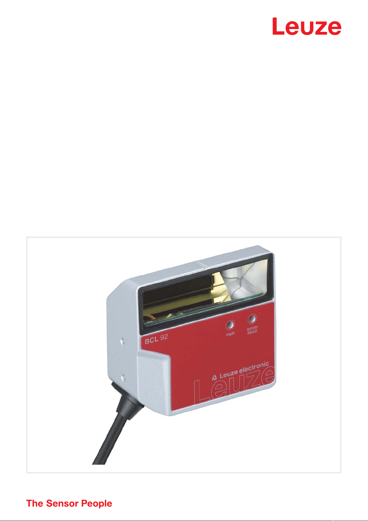
BCL 92
Bar code reader
We reserve the right to make technical changes
EN • 2020-04-28 • 50144007

© 2020
Leuze electronic GmbH + Co. KG
In der Braike 1
Leuze electronic GmbH + Co. KG BCL 92 2

Table of contents
1 About this document ............................................................................................5
1.1 Used symbols and signal words .............................................................................................5
1.2 Terms and abbreviations ........................................................................................................6
2 Safety .....................................................................................................................7
2.1 Intended use ........................................................................................................................... 7
2.2 Foreseeable misuse ............................................................................................................... 8
2.3 Competent persons ................................................................................................................ 8
2.4 Disclaimer ............................................................................................................................... 9
2.5 Laser safety notices................................................................................................................ 9
3 Device description ..............................................................................................10
3.1 Device overview.................................................................................................................... 10
3.1.1 About the bar code reader................................................................................................. 10
3.1.2 Stand-alone operation .......................................................................................................10
3.2 Performance characteristics .................................................................................................10
3.3 Device construction .............................................................................................................. 11
3.4 Connection technology .........................................................................................................11
3.5 Display elements .................................................................................................................. 11
Table of contents
4 Mounting..............................................................................................................12
4.1 Selecting a mounting location............................................................................................... 12
5 Electrical connection..........................................................................................14
5.1 Operating voltage ................................................................................................................. 14
5.2 Housing ground .................................................................................................................... 15
5.3 Pin assignment .....................................................................................................................15
5.4 Connecting bar code reader to MA150 connection unit....................................................... 16
5.5 Switching inputs.................................................................................................................... 18
5.6 Switching outputs.................................................................................................................. 19
5.7 Cable lengths and shielding.................................................................................................. 19
5.8 PC or terminal connection .................................................................................................... 19
6 Configuration and diagnostics software - SensorStudio...............................20
6.1 System requirements............................................................................................................ 20
6.2 Installing SensorStudio ........................................................................................................ 21
6.2.1 Downloading configuration software .................................................................................21
6.2.2 Installing the SensorStudio FDT frame ............................................................................21
6.2.3 Install the communication DTM and device DTM.............................................................. 21
6.2.4 Connecting device to PC...................................................................................................21
6.3 Starting SensorStudio.......................................................................................................... 22
6.4 Exiting SensorStudio ........................................................................................................... 23
Leuze electronic GmbH + Co. KG BCL 92 3

Table of contents
6.5 Configuration parameters .....................................................................................................23
6.5.1 Decode tab ........................................................................................................................24
6.5.2 Output tab.......................................................................................................................... 27
6.5.3 Control tab.........................................................................................................................29
6.5.4 Host interface tab ..............................................................................................................30
6.5.5 Reference code tab ...........................................................................................................31
6.5.6 Switching input tab ............................................................................................................33
6.5.7 Switching output tab ..........................................................................................................34
6.6 Diagnosis .............................................................................................................................. 35
6.7 Firmware Reload................................................................................................................... 36
7 Starting up the device - Configuration..............................................................37
7.1 Measures to be performed prior to the initial commissioning ............................................... 37
7.2 Starting the device ................................................................................................................ 37
7.2.1 Power-on test ....................................................................................................................37
7.2.2 Interface ............................................................................................................................37
7.2.3 Online commands .............................................................................................................37
7.2.4 Problems ...........................................................................................................................37
7.3 Starting up with factory settings............................................................................................ 38
7.4 Setting the configuration parameters.................................................................................... 38
7.4.1 Service mode ....................................................................................................................39
7.4.2 Parameter sets ..................................................................................................................40
8 Online commands...............................................................................................41
8.1 Overview of commands and parameters .............................................................................. 41
8.2 General online commands.................................................................................................... 42
8.3 Online commands for system control ................................................................................... 47
8.4 Online commands for the parameter set operations............................................................. 48
9 Care, maintenance and disposal .......................................................................51
10 Diagnostics and troubleshooting ......................................................................52
11 Service and support ...........................................................................................53
12 Technical data .....................................................................................................54
12.1 General specifications .......................................................................................................... 54
12.2 Reading fields ....................................................................................................................... 56
12.3 Dimensioned drawings ......................................................................................................... 59
13 Order guide and accessories.............................................................................61
13.1 Type overview....................................................................................................................... 61
13.2 Accessories........................................................................................................................... 62
14 EC Declaration of Conformity ............................................................................63
15 Appendix..............................................................................................................64
15.1 Bar code samples ................................................................................................................. 64
Leuze electronic GmbH + Co. KG BCL 92 4
About this document
1 About this document
1.1 Used symbols and signal words
Tab.1.1: Warning symbols and signal words
Symbol indicating dangers to persons
Symbol indicating dangers from harmful laser radiation
Symbol indicating possible property damage
NOTE Signal word for property damage
Indicates dangers that may result in property damage if the measures for
danger avoidance are not followed.
CAUTION Signal word for minor injuries
Indicates dangers that may result in minor injury if the measures for danger
avoidance are not followed.
WARNING Signal word for serious injury
Indicates dangers that may result in severe or fatal injury if the measures
for danger avoidance are not followed.
Tab.1.2: Other symbols
Symbol for tips
Text passages with this symbol provide you with further information.
Symbol for action steps
Text passages with this symbol instruct you to perform actions.
Symbol for action results
Text passages with this symbol describe the result of the preceding action.
Leuze electronic GmbH + Co. KG BCL 92 5

About this document
1.2 Terms and abbreviations
Tab.1.3: Terms and abbreviations
BCL Bar code reader
DNC This PIN must not be connected
(Do Not Connect)
DTM Software device manager
(Device Type Manager)
EMC Electromagnetic compatibility
EN European standard
FDT Software frame for management of device managers (DTM)
(Field Device Tool)
FE Functional earth
GUI Graphical user interface
HID Device class for input devices with which users directly interact
(Human Interface Device)
NC This pin is not contacted at the device
(Not Connected)
SELV Safe Extra Low Voltage
PLC Programmable Logic Control
(corresponds to Programmable Logic Controller (PLC))
SW_IN Switching input
SW_OUT Switching output
Leuze electronic GmbH + Co. KG BCL 92 6
Safety
2 Safety
This bar code reader was developed, manufactured and tested in accordance with the applicable safety
standards. It corresponds to the state of the art.
2.1 Intended use
Bar code readers of the BCL92 series are conceived as stationary scanners with integrated decoder for all
current bar codes used for automatic object detection.
Areas of application
Bar code readers of the BCL92 series are designed for the following areas of application:
• Automatic analyzers
• Robotics and automation technology
• Material flow
• Labeling and packaging machines
• For space-critical bar code reading tasks
• Applications with large reading field with small modules
CAUTION
Observe intended use!
The protection of personnel and the device cannot be guaranteed if the device is operated in a
manner not complying with its intended use.
Ä Only operate the device in accordance with its intended use.
Ä LeuzeelectronicGmbH+Co.KG is not liable for damages caused by improper use.
Ä Read these operating instructions before commissioning the device. Knowledge of the oper-
ating instructions is an element of proper use.
NOTICE
Comply with conditions and regulations!
Ä Observe the locally applicable legal regulations and the rules of the employer's liability insur-
ance association.
CAUTION
UL applications!
For UL applications, use is only permitted in LPS/Class 2 circuits in accordance with the NEC
(National Electric Code).
Leuze electronic GmbH + Co. KG BCL 92 7
Safety
2.2 Foreseeable misuse
Any use other than that defined under "Intended use" or which goes beyond that use is considered improper use.
In particular, use of the device is not permitted in the following cases:
• in rooms with explosive atmospheres
• in circuits which are relevant to safety
• for medical purposes
NOTICE
Do not modify or otherwise interfere with the device!
Ä Do not carry out modifications or otherwise interfere with the device. The device must not be
tampered with and must not be changed in any way.
Ä The device must not be opened. There are no user-serviceable parts inside.
Ä Repairs must only be performed by Leuze electronic GmbH + Co. KG.
NOTICE
Ä To increase the decoding reliability, it is recommended that only the actually needed code
types be enabled.
Ä If there are very high requirements on reading reliability, the use of additional processes is
recommended, e.g.:
ð Device side: check digits, multiple evaluation by setting Equal Scans to min. ≥2
ð Application side: reading moving codes
ð System side: plausibility checks of the bar code information
2.3 Competent persons
Connection, mounting, commissioning and adjustment of the device must only be carried out by competent
persons.
Prerequisites for competent persons:
• They have a suitable technical education.
• They are familiar with the rules and regulations for occupational safety and safety at work.
• They are familiar with the operating instructions for the device.
• They have been instructed by the responsible person on the mounting and operation of the device.
Certified electricians
Electrical work must be carried out by a certified electrician.
Due to their technical training, knowledge and experience as well as their familiarity with relevant standards
and regulations, certified electricians are able to perform work on electrical systems and independently detect possible dangers.
In Germany, certified electricians must fulfill the requirements of accident-prevention regulations DGUV
(German Social Accident Insurance) provision 3 (e.g. electrician foreman). In other countries, there are respective regulations that must be observed.
Leuze electronic GmbH + Co. KG BCL 92 8
Safety
1
1
2.4 Disclaimer
LeuzeelectronicGmbH+Co.KG is not liable in the following cases:
• The device is not being used properly.
• Reasonably foreseeable misuse is not taken into account.
• Mounting and electrical connection are not properly performed.
• Changes (e.g., constructional) are made to the device.
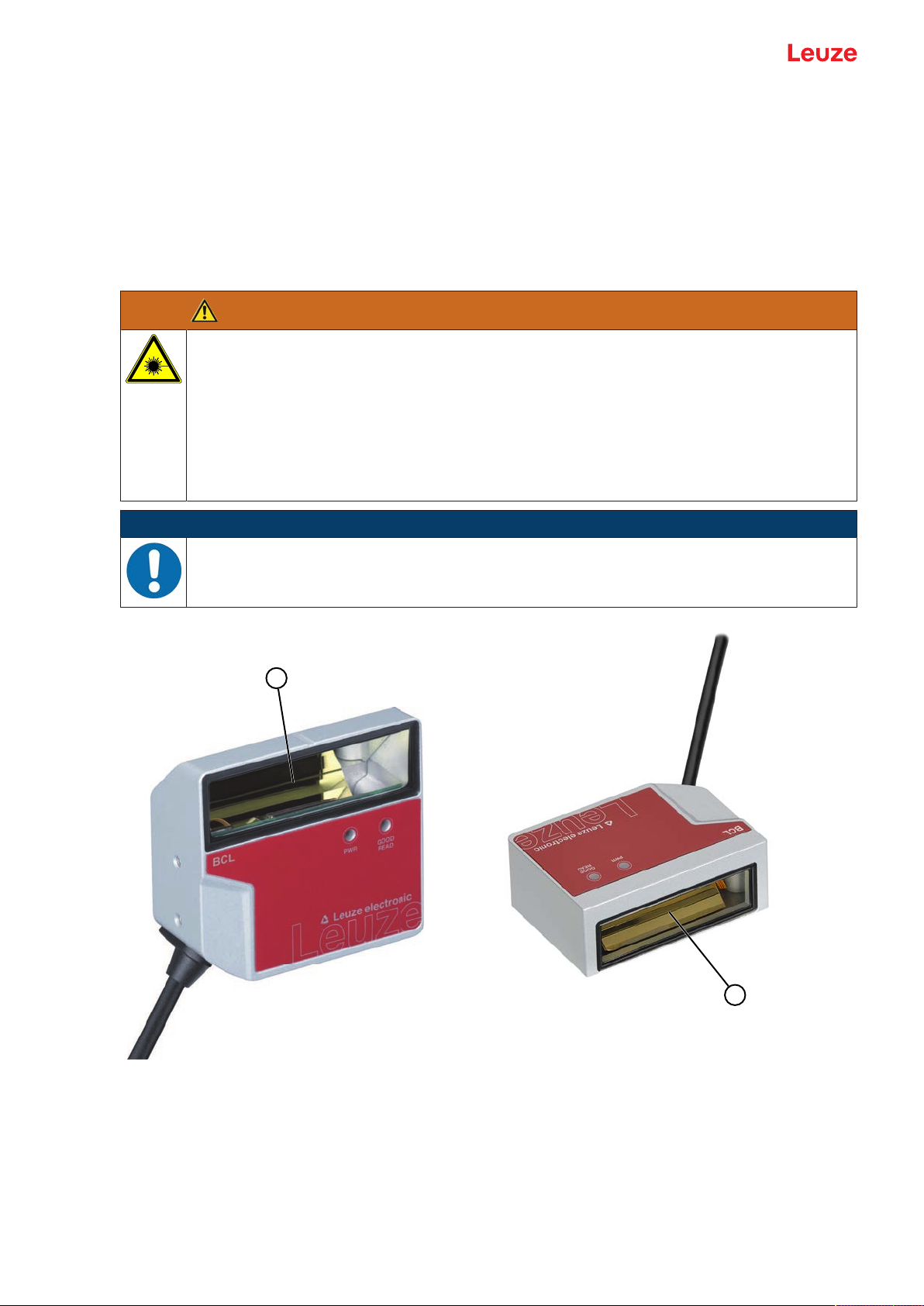
2.5 Laser safety notices
ATTENTION
LASER RADIATION – CLASS 1 LASER PRODUCT
The device satisfies the requirements of IEC/EN 60825-1:2014 safety regulations for a product
of laser class1 and complies with 21 CFR 1040.10 except for conformance with IEC 60825-1
Ed. 3., as described in Laser Notice No. 56, dated May 8, 2019.
Ä Observe the applicable statutory and local laser protection regulations.
Ä The device must not be tampered with and must not be changed in any way.
There are no user-serviceable parts inside the device.
Repairs must only be performed by Leuze electronic GmbH + Co. KG.
NOTICE
Laser aperture!
The glass optics cover is the only aperture through which laser radiation may be observed on
this product.
1 Laser aperture
Fig.2.1: Laser aperture
Leuze electronic GmbH + Co. KG BCL 92 9

Device description
3 Device description
3.1 Device overview
3.1.1
3.1.2
About the bar code reader
The bar code reader is a laser scanner with integrated decoder for all commonly used bar codes, e.g.
2/5Interleaved, Code39, Code128, EAN etc.
• The reading field is optimized for the reading of sample tubes, reagent containers, etc., in laboratory
automation.
• Reliable reading of 80 mm high code labels at a short distance.
• Due to the small dimensions of the unit and the variants with frontal or lateral beam exit, the bar code
reader can also be used in highly constrained spaces.
• The many possible configurations of the device allow it to be adapted to a multitude of reading tasks.
• Information on technical data and characteristics: see chapter 12 "Technical data".
Stand-alone operation
The bar code reader is operated as a "stand-alone" single device. The electrical connection of the operating voltage, the interface and the switching input is made via a 12-pin M12 connector or via a 15-pin Sub-D
connector.
3.2 Performance characteristics
• Laser scanner with integrated decoder; lateral or frontal beam exit
• High-resolution optics
• Resolution 0.165mm…0.5mm
Reading of all common codes of module size 165…500μm (6.5…20mil) at a reading field height of
≥80mm, even with a reading distance of 25 mm for devices with lateral beam exit
• Reading distance 25mm…260mm
• Scanning rate of 600scans/s facilitates reliable reading, even while in motion
• Compact design for simple integration, even in constrained spaces
• Two switching inputs and two switching outputs
• Sturdy diecast zinc housing
• Connection cable 0.8m or 3m with Sub-D connector, 15-pin
• Connection cable 0.8m with M12 connector, 12-pin
• Process and service interface RS232
Leuze electronic GmbH + Co. KG BCL 92 10
Device description
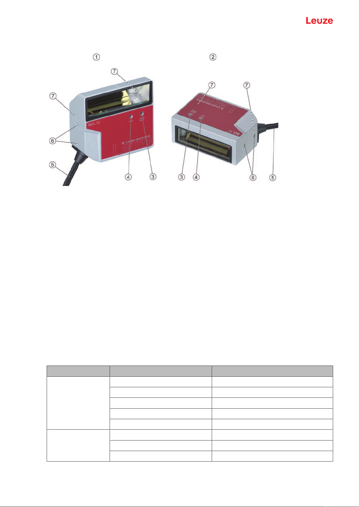
3.3 Device construction
1 BCL92 SM..0: lateral beam exit
2 BCL92 SM..2: frontal beam exit
3 Indicator diode – decode LED
4 Indicator diode – status LED
5 Connection cable with Sub-D connector, 15-pin
Connection cable with M12 connector, 12-pin
6 M2.5 mounting threads on the device side
7 M3 mounting threads on the rear of the device
Fig.3.1: Device construction of the BCL92
3.4 Connection technology
Connection cable with 15-pin Sub-D connector or connection cable with 12-pin M12 connector:
• Voltage supply
• Two switching inputs
• Two switching outputs
• Process and service interface RS232
3.5 Display elements
Located on the front of the device are two LEDs that indicate the readiness for operation and the read status.
LED Display Description
Status LED
(PWR)
Green, flashing Initialization phase
Green, continuous light Operational readiness
Red, flashing 200ms Warning
Red, continuous light Error, no function
Orange, flashing 200ms Service operation
Decode LED
(GOOD READ)
Green, 200ms on Reading successful
Red, 200ms off No reading result
Orange, continuous light Reading gate active
Leuze electronic GmbH + Co. KG BCL 92 11

Mounting
4 Mounting
Ä Observe the mounting instructions (see chapter 4.1 "Selecting a mounting location").
Ä Fasten the bar code reader on the mounting threads (see chapter 3.3 "Device construction"):
• M3 mounting threads on the rear of the device
• M2.5 mounting threads on the device side
4.1 Selecting a mounting location
NOTICE
The size of the bar code module influences the maximum reading distance and the width of the
reading field.
Ä When selecting a mounting location and/or the bar code label, take into account the different
reading characteristics of the bar code reader with various bar code modules.
NOTICE
Observe when choosing the mounting location!
Ä Maintain the permissible environmental conditions (humidity, temperature).
Ä Avoid possible soiling of the reading window due to liquids, abrasion by boxes, or packaging
material residues.
Ä Ensure that there is the lowest possible chance of damage to the bar code reader by me-
chanical collision or jammed parts.
Ä Avoid possible ambient light influence (no direct sunlight).
In order to select the right mounting location, several factors must be considered:
• Size, orientation, and position tolerance of the bar codes on the objects to be scanned.
• The reading field of the bar code reader in relation to the bar code module width.
• The resulting minimum and maximum reading distance from the respective reading field with the respective module width (see chapter 12.2 "Reading fields").
• alignment of the bar code reader for avoiding reflections.
• distance between bar code reader and host system with respect to the interface.
The best read results are obtained if the following prerequisites are fulfilled:
• The reading distance lies in the middle area of the reading field.
• There is no direct sunlight and protect against ambient light effects.
• The bar code labels are of good print quality and have good contrast ratios.
• You are not using glossy labels.
• The bar code is moved past the reading window with an angle of rotation of approx. 15°.
Leuze electronic GmbH + Co. KG BCL 92 12
Mounting
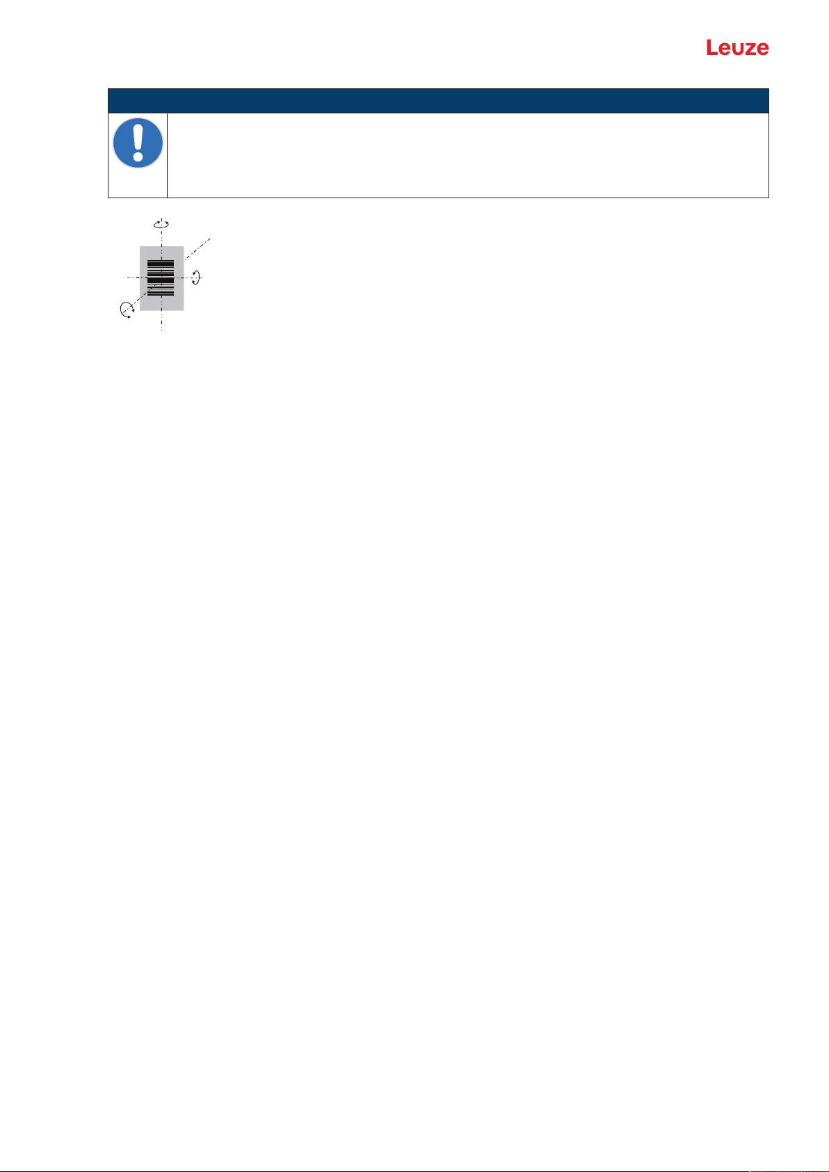
α
β
γ
α Azimuth angle
β Angle of inclination
γ Angle of rotation
Fig.4.1: Definition of the reading angles
NOTICE
Avoid direct reflection of the laser beam!
The beam exits the bar code reader perpendicular to the reading window.
Ä The bar code label must be rotated by >10 ° to avoid a reflection of the laser beam in the
case of glossy labels.
Recommended angle of rotation: γ>10°
Leuze electronic GmbH + Co. KG BCL 92 13
Electrical connection
5 Electrical connection
CAUTION
Safety notices!
Ä The bar code reader is completely sealed and must not be opened.
Ä Do not try to open the device under any circumstances, as this avoids both degree of pro-
tection IP54 and the warranty.
Ä Before connecting the device, be sure that the supply voltage agrees with the value printed
on the name plate.
Ä Connection of the device and maintenance work while under voltage must only be carried
out by a qualified electrician.
Ä The power supply unit for the generation of the supply voltage for the bar code reader and
the corresponding connection units must have a secure electrical insulation according to
IEC60742 (SELV).
Ä If faults cannot be rectified, take the device out of operation and protect it from accidentally
being started.
CAUTION
UL applications!
For UL applications, use is only permitted in LPS/Class 2 circuits in accordance with the NEC
(National Electric Code).
NOTICE
Laying cables!
Ä Lay all connection cables and signal lines within the electrical installation space or perma-
nently in cable ducts.
Ä Lay the cables and lines so that they are protected against external damages.
Ä For further information: see ISO13849-2, Table D.4.
The electrical connection is established via the connection cable (see chapter 5.3 "Pin assignment"):
• Connection cable with Sub-D connector, 15-pin
• Connection cable with M12 connector, 12-pin
NOTICE
You can optionally use an MA150 modular connection unit for the electrical connection.
The bar code reader is provided with the following interfaces:
• Voltage supply
• Two switching inputs
• Two switching outputs
• Process and service interface RS232
You can configure the functions of the switching inputs or switching outputs according to your requirements
via the SensorStudio configuration software (see chapter 6 "Configuration and diagnostics software - SensorStudio").
5.1 Operating voltage
The operating voltage of the bar code reader is 10…30VDC.
• NEC Class2
• Protection class III with SELV Power Supply
The operating voltage is fed in via the connection cable (see chapter 5.3 "Pin assignment").
Leuze electronic GmbH + Co. KG BCL 92 14
Electrical connection
1
2
3
4
5
6
7
8
9
10
11
12
13
14
15
Res
.
Res.
Res.
Res.
SWIN1
SWIN2
SWOUT1
RXD
TXD
Res.
Res.
GNDIN
Res.
SWOUT2
VIN
5.2 Housing ground
To avoid electromagnetic interference, a low-impedance connection is necessary from the housing to the
machine ground.
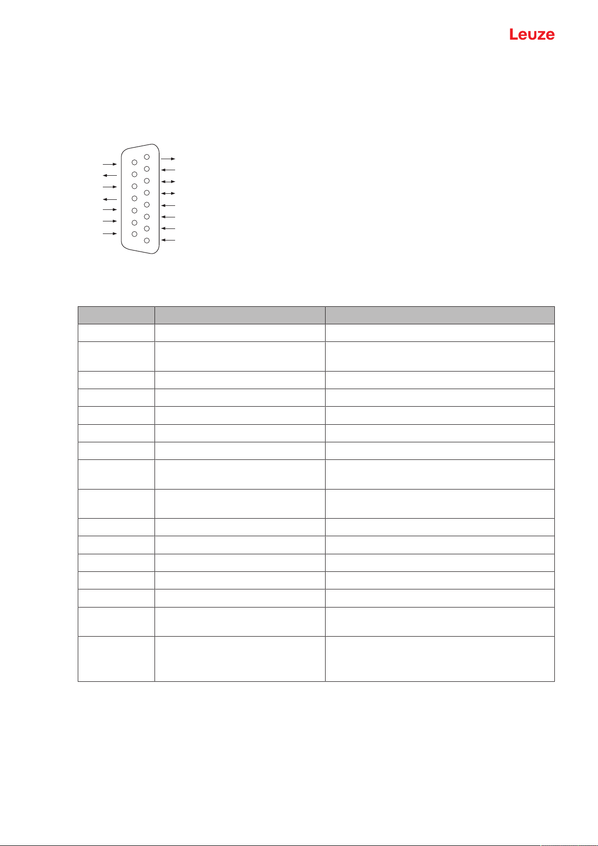
5.3 Pin assignment
Fig.5.1: Pin assignment for Sub-D connector, 15-pin
Tab.5.1: PWR/SWIO/RS232 – Sub-D connector
Pin No. Designation Assignment
1 Res. Reserved
2 SWIN1 Digital switching input1
+12…+30VDC
3 Res. Reserved
4 Res. Reserved
5 Res. Reserved
6 SWOUT2 Digital switching output2
7 Res. Reserved
8 VIN Operating voltage
+10…+30VDC
9 SWIN2 Digital switching input2
+12…+30VDC
10 SWOUT1 Digital switching output1
11 RXD RS232: RXD signal
12 TXD RS232: TXD signal
13 Res. Reserved
14 Res. Reserved
15 GNDIN Negative operating voltage
0VDC
Metal flange FE (functional earth) Connection cable shield.
The shield of the connection cable is on the metal
flange of the Sub-D connector.
Leuze electronic GmbH + Co. KG BCL 92 15
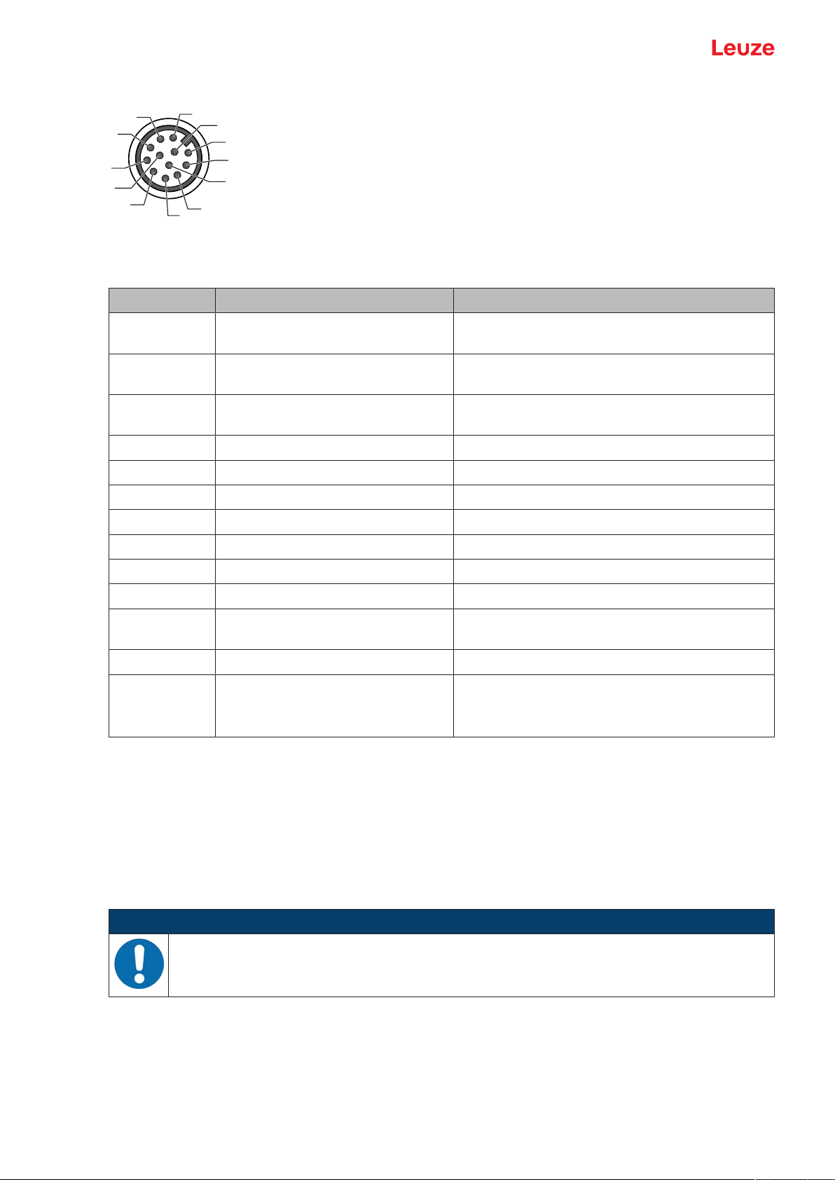
Electrical connection
4
11
3
2
1
10
9
8
12
5
6
7
Fig.5.2: Pin assignment for M12 connector, 12-pin, A-coded
Tab.5.2: PWR/SWIO/RS232 - M12 connector
Pin No. Designation Assignment
1 VIN Operating voltage
2 GNDIN Negative operating voltage
3 SWIN1 Digital switching input1
4 SWOUT1 Digital switching output1
+10…+30VDC
0VDC
+12…+30VDC
5 FE Functional earth
6 n.c.
7 Res. Reserved
8 Res. Reserved
9 RXD RS232: RXD signal
10 TXD RS232: TXD signal
11 SWIN2 Digital switching input2
+12…+30VDC
12 SWOUT2 Digital switching output2
Thread (M12
connector)
FE (functional earth) Connection cable shield.
The shield of the connection cable is on the
thread of the M12 connector.
5.4 Connecting bar code reader to MA150 connection unit
The signals from the bar code reader are distributed in the machine decentrally via the MA150 modular
connection unit. The following components can be connected to the MA150 connection unit:
• BCL92 series bar code reader
• Photoelectric sensor/diffuse sensor to activate the bar code reader
• Voltage supply
• Serial communication RS232
NOTICE
Supply voltage!
A supply voltage of 18…30VDC is necessary if connecting via the modular connection unit.
Leuze electronic GmbH + Co. KG BCL 92 16
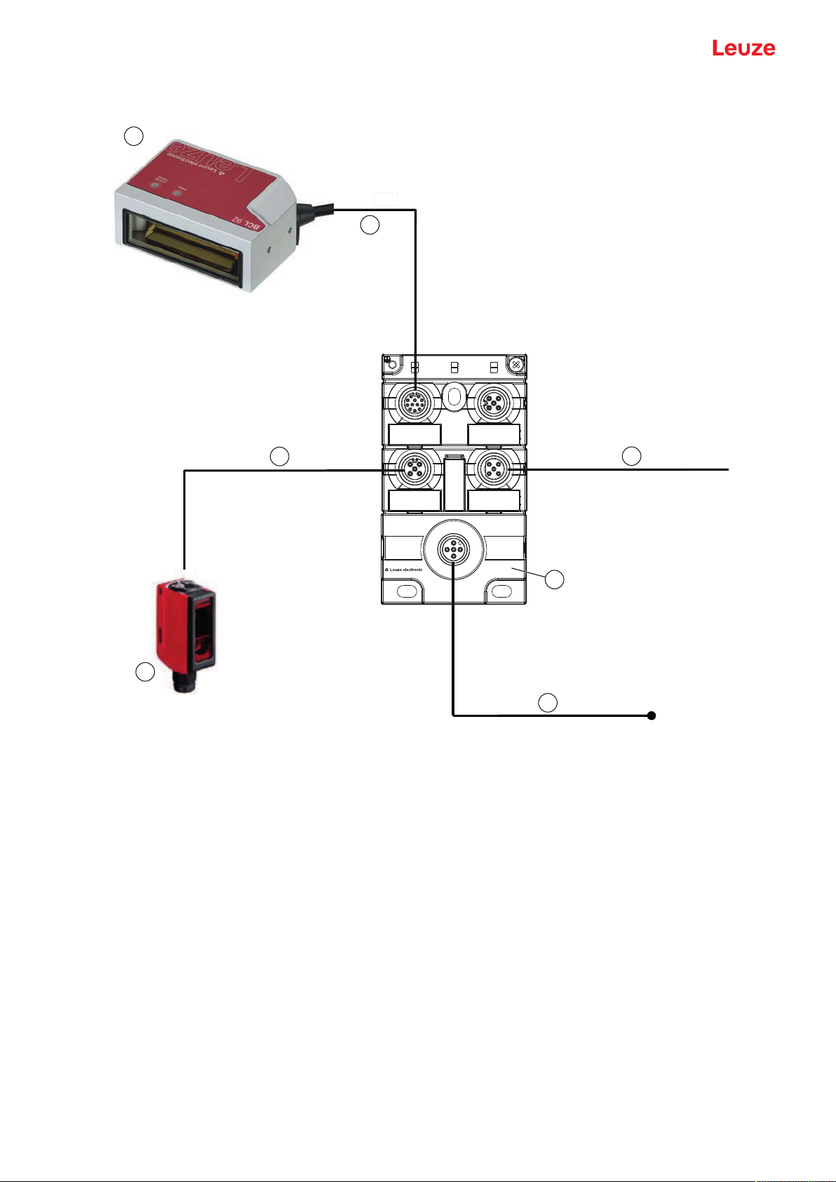
Electrical connection
DC 18 V … 30 V
P
WR/SWIO3/SWIO4
PWR/SWIO1-4/
RS232-422
PWR/SWI1
RS 232
SWIO3
MA 150
Art.-No.
01301095
SWIO4
PWR
PWR/SWIO
IDENT
SWO2
SWI1 HOST
2
3
1
4
5
7
6
Circuit diagram example for electrical installation with MA150 connection unit
1 Bar code reader BCL92
2 MA150 modular connection unit
3 Sensor (photoelectric sensor/diffuse sensor)
4 Cable, M12 connector/open cable end, 5-pin, 2m
e.g., 50108595
5 Cable, M12 socket/open cable end, 5-pin, 2m
e.g., 50104555
6 Cable, M12 socket/connector, 4-pin, 2m
e.g., 50110126
7 Cable, M12 socket/connector, 12-pin, 2m
e.g., 50130284
Fig.5.3: Circuit diagram example with MA150 connection unit
Leuze electronic GmbH + Co. KG BCL 92 17
Electrical connection
+ 12 ... + 30 V DC
SW_IN 1/SW_IN 2
GND
+ 12 … + 30 V DC
GND
1
+ 12 ... + 30 V DC
SW_IN 1/SW_IN 2
GND
GND
+ 12 … + 30 V DC
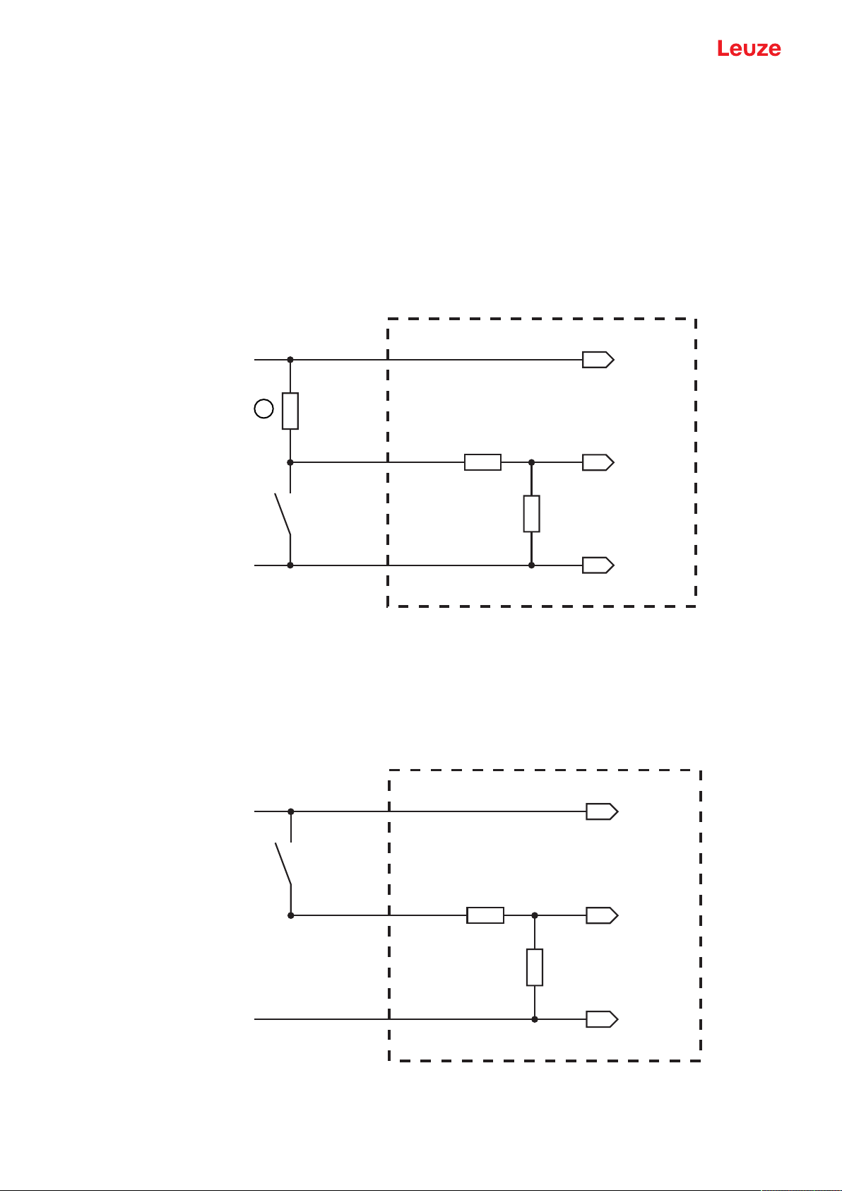
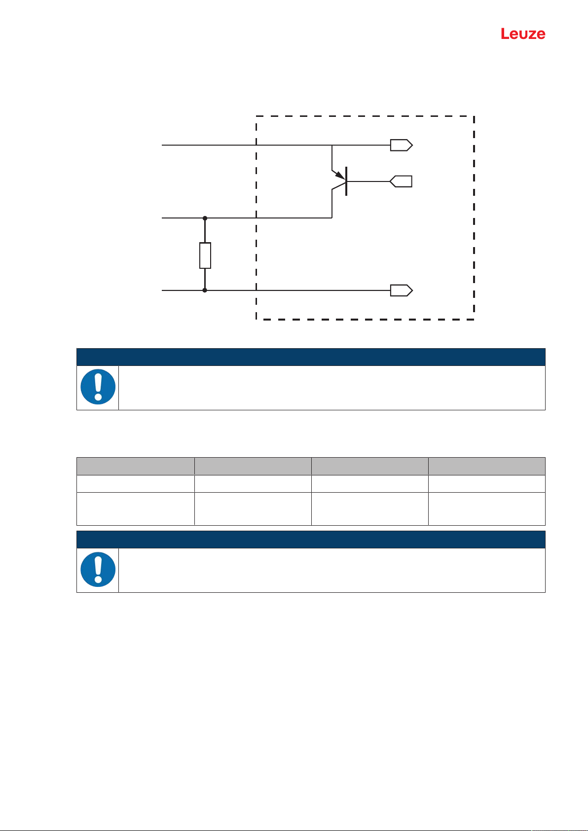
5.5 Switching inputs
You can trigger a read process via switching input connections SW_IN1 and SW_IN2.
The function of switching inputs SW_IN1 and SW_IN2 is determined from the configuration, which is set,
e.g., via the SensorStudio configuration software (see chapter 6 "Configuration and diagnostics software SensorStudio").
Depending on how the switching input is actuated, you can operate it both as NPN (low = active) as well as
PNP (high = active).
NPN actuation
• Standard setting (low = active)
• We recommend wiring a 2.2kΩ pull-up resistor as defined cable termination.
1 Pull-up resistor, 2.2kΩ
Fig.5.4: Switching input for connection variant NPN (standard setting)
PNP actuation
With the "inverted" setting (high = active), you can trigger a read process by applying a voltage of
+12VDC…+30VDC at SW IN.
Connection version NPN: standard setting (low = active); input resistance: 13.3kΩ
Connection version PNP: inverted setting (high = active); input resistance: 13.3kΩ
Fig.5.5: Switching input for connection variant PNP ("inverted" setting)
Leuze electronic GmbH + Co. KG BCL 92 18
Electrical connection
SW_OUT
2 kΩ
GND
+ 10 … + 30 V
5.6 Switching outputs
In the basic setting, switching output SWOUT1 switches on NoRead and switching output SWOUT2
switches on GoodRead.
5.7 Cable lengths and shielding
5.8 PC or terminal connection
Fig.5.6: Switching output
NOTICE
Maximum loading of the switching output!
Ä Do not load the switching output of the bar code reader with more than 20mA at +10…30
VDC!
Ä Observe the maximum cable lengths:
Connection Interface Max. cable length Shielding
BCL92 RS232 <3m Required
Switching inputs
Switching outputs
NOTICE
Ä Make certain that the cables of the RS232 interface are shielded should a cable extension
be necessary.
Via the RS232 service interface, you can configure the bar code reader by means of a PC or a terminal
program. For this, you need an RS232 connection that establishes the RxD, TxD and GND connections
between PC and bar code reader (see chapter 5.3 "Pin assignment").
<3m Not necessary
Leuze electronic GmbH + Co. KG BCL 92 19
Configuration and diagnostics software - SensorStudio
6 Configuration and diagnostics software - SensorStudio
The SensorStudio configuration software provides a graphical user interface for the operation, configuration and diagnostics of the device via the RS232 service interface.
A device that is not connected to the PC can be configured offline.
Configurations can be saved and reopened as projects for transferring back to the device at a later time.
NOTICE
Only use the SensorStudio configuration software for products manufactured by Leuze.
The SensorStudio configuration software is offered in the following languages: German, English, French, Italian and Spanish.
The FDT frame application of the SensorStudio supports all languages; all languages may not
be supported in the device DTM (Device Type Manager).
The SensorStudio configuration software is designed according to the FDT/DTM concept:
• You make the individual configuration settings for the bar code reader in the Device Type Manager
(DTM).
• The individual DTM configurations of a project can be called up via the frame application of the Field
Device Tool (FDT).
• Communication DTM for bar code readers: LeCommInterface
• Device DTM for the BCL92 bar code reader
Procedure for the installation of the software and hardware:
Ä Install the SensorStudio configuration software on the PC.
Ä Install the communication and device DTM. Communication and device DTM are included in the Le-
AnalysisCollectionSetup installation package.
Ä Create device DTM for BCL92 in the project tree of the SensorStudio FDT frame.
Ä Connect bar code reader to PC (see chapter 5.8 "PC or terminal connection").
Ä Activate service interface on bar code reader (see chapter 7.4.1 "Service mode").
6.1 System requirements
To use the SensorStudio configuration software, you need a PC or laptop with the following specifications:
Tab.6.1: System requirements for SensorStudio installation
Operating system WindowsXP or higher (32bit, 64bit)
Computer Processor type: 1GHz or higher
Graphics card At least 1024x768 pixels
Required hard disk capacity for SensorStudio and
communication DTM
NOTICE
WindowsVista
Windows7
Windows8
Serial COM interface
CD-ROM drive
Main memory (RAM): at least 64MB
Keyboard and mouse or touchpad
35MB
Administrator privileges on the PC are necessary for installing SensorStudio.
Leuze electronic GmbH + Co. KG BCL 92 20

Configuration and diagnostics software - SensorStudio
6.2 Installing SensorStudio
NOTICE
The installation files of the SensorStudio configuration software must be downloaded from the
Internet at www.leuze.com. For subsequent updates, you can find the most recent version of
the SensorStudio installation software on the Internet at www.leuze.com.
6.2.1
6.2.2
Downloading configuration software
Ä Call up the Leuze home page: www.leuze.com
Ä Enter the type designation or part number of the device as the search term.
Ä The configuration software can be found on the product page for the device under the Downloads tab.
Installing the SensorStudio FDT frame
NOTICE
First install the software!
Ä Do not yet connect the device to the PC.
Ä First install the software.
NOTICE
If FDT frame software is already installed on your PC, you do not need the SensorStudio installation.
You can install the communication DTM and the device DTM in the existing FDT frame. Communication DTM and device DTM are included in the LeAnalysisCollectionSetup installation
package.
Ä Start the PC.
Ä Download the configuration software from the Internet to the PC (see chapter 6.2.1 "Downloading con-
figuration software"). Unpack the installation package.
Ä Start the SensorStudioSetup.exe file.
Ä Follow the instructions on the screen.
6.2.3
6.2.4
Install the communication DTM and device DTM
Prerequisites:
ü An FDT frame is installed on the PC.
Ä Start the LeAnalysisCollection.exe file from the installation package and follow the instructions on the
screen.
Connecting device to PC
The device is connected to the PC via the RS232 interface.
You need an RS232 connection that establishes the RxD, TxD and GND connections between PC and device (see chapter 5.8 "PC or terminal connection").
The +10VDC…+30VDC voltage supply is to be fed in externally (see chapter 5.1 "Operating voltage").
Leuze electronic GmbH + Co. KG BCL 92 21

Configuration and diagnostics software - SensorStudio
6.3 Starting SensorStudio
Prerequisites:
ü The device has been mounted (see chapter 4 "Mounting") and connected (see chapter 5 "Electrical
connection") correctly.
ü The device is connected to the PC via the RS232 interface (see chapter 6.2.4 "Connecting device to
PC").
ü The SensorStudio configuration software is installed on the PC (see chapter 6.2 "Installing SensorStu-
dio").
Ä Start the SensorStudio configuration software by double-clicking the [SensorStudio] icon (
).
ð The mode selection of the Project Wizard is displayed.
Ä Select the Device selection without communication connection (offline) configuration mode and
click on [Next].
ð The Project Wizard displays the device selection list of the configurable devices.
Fig.6.1: Device selection for the BCL92
Ä Select BCL92 in the device selection and click on [Next].
ð The device manager (DTM) of the connected bar code reader starts with the offline view for the Sen-
sorStudio configuration project.
Ä Establish the online connection to the connected bar code reader.
ð In the SensorStudio FDT frame, click on the [Establish connection with device] button (
ð In the SensorStudio FDT frame, click on the [Upload parameters to device] button (
).
).
ð The current configuration data is displayed in the device manager (DTM).
Leuze electronic GmbH + Co. KG BCL 92 22

Configuration and diagnostics software - SensorStudio
Fig.6.2: Configuration project: device manager for BCL92
Ä The menus of the SensorStudio device manager (DTM) can be used to change or read out the config-
uration of the connected device.
ð The user interface of the SensorStudio device manager (DTM) is largely self-explanatory.
ð The online help system provides information on the menu items and adjustment parameters. Select
the Help menu item in the menu [?].
Ä Transfer the modified configuration parameters to the device.
ð If a connection exists, click on the [Download parameters to device] (
6.4 Exiting SensorStudio
After completing the configuration settings, close the SensorStudio configuration software.
Ä Exit the program via File > Exit.
Ä Save the configuration settings as a configuration project on the PC.
6.5 Configuration parameters
In this chapter, you will find information and explanations on the configuration parameters of the device
manager (DTM) for the bar code reader.
NOTICE
This chapter does not include a complete description of the SensorStudio configuration software. Complete information on the FDT frame menu and on the functions in the device manager
(DTM) can be found in the online help system.
) button on the task bar.
NOTICE
The online help system displays information on the menu items and configuration parameters
for each function. Select the Help menu item in the menu [?]
The SensorStudio configuration software offers the following buttons in the CONFIGURATION menu:
•
: [Reset all parameters in the GUI to their factory default settings]
Resets all parameters in the graphical user interface to the factory settings.
Leuze electronic GmbH + Co. KG BCL 92 23

Configuration and diagnostics software - SensorStudio
6.5.1
Decode tab
Fig.6.3: Decode tab
Code table
(CODE TABLE)
Here, the codes which are to be decoded are set.
Codes which are not enabled are not decoded!
Note:
We recommend enabling only the code types which are to actually
be read with the corresponding element numbers.
Element number In the field Element number, up to three element entries may be en-
tered.
A range of permissible elements is indicated by a dash:
e.g., 4-40 elements.
To select a range, set the check mark beneath Interval mode. Up to
three fixed element numbers with comma:
e.g.: 8,13 elements
Both are also possible, but the range must be specified first (select
Interval mode):
e.g.: 4-10,20 elements
Labels to be decoded
(COMPLETENESS/Number of
Here, the number of the bar codes to be decoded within a read cycle
(one reading gate) is set.
bar codes)
NOTICE
If the code EAN128 is to be read, 3 additional characters are to be set for the code identifier.
Leuze electronic GmbH + Co. KG BCL 92 24

Configuration and diagnostics software - SensorStudio
Properties
(Symbology Properties)
In the Symbology Properties window to the right of the respective
code, after Element number, the code-specific settings such as the
check digit can be selected.
Alternatively, you can select the property settings directly via the navigation tree with the [Symbologies] button.
The properties can be individually set for each code type.
Fig.6.4: Standard settings of the Properties dialog box (SYMBOLOGY PROPERTIES)
Leuze electronic GmbH + Co. KG BCL 92 25
Configuration and diagnostics software - SensorStudio
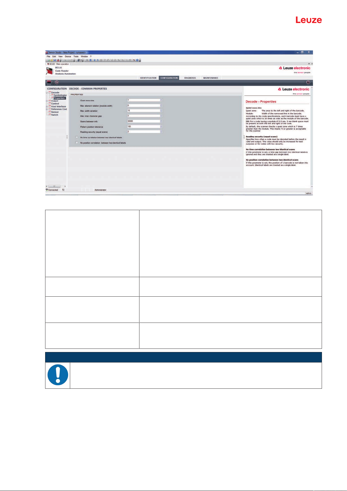
Properties dialog box (Common Properties)
Fig.6.5: Standard settings of the Properties dialog box (COMMON PROPERTIES)
Quiet zone minimum size (in module widths)
Quiet zone size
Quiet zone: the area to the left and right of the bar code
Module: width of the narrowest bar in the bar code
According to code specifications, each bar code must have a quiet
zone that is 10x as wide as the module of the bar code.
Example: For a code with a module of 0.5mm, there must be 5mm
of empty space to the left and right.
By default, the scanner checks a quiet zone that is 7x greater than
the module.
Reading reliability
(Reading reliability (equal scans))
No time correlation between two
identical scans
No position correlation between
two identical scans
Under reading reliability (equal scans), it is possible to select how
often a code must be decoded before the result is valid and output
If this parameter is set, a gap between two identical labels is ignored
and they are treated as a single label.
If this parameter is set, then the position of a bar code label in the
reading beam is not taken into account. Identical labels are treated
as a single label.
NOTICE
In general, the remaining parameters must not be changed. In the worst case, this could corrupt
the read result!
Leuze electronic GmbH + Co. KG BCL 92 26

Configuration and diagnostics software - SensorStudio
6.5.2
Output tab
Fig.6.6: Output tab (OUTPUT FORMAT)
Output header Select from the options listed below. The output
header is sent in a separate message before the
read result.
Label header The label header is set directly before the code
data.
Label footer The label footer is appended directly to the code
data.
Message mode Selects whether the bar codes read are sent in con-
catenation or separately as individual strings.
NOTICE
The structure of this message string is depicted symbolically in the preview window.
Text in the case of misreading
(No read string)
This character is set for each unrecognized bar
code. Multiple characters (=string) may be entered
here. Up to 20 characters are possible.
Leuze electronic GmbH + Co. KG BCL 92 27

Configuration and diagnostics software - SensorStudio
Properties dialog box (Common Properties)
Set the desired formatting modes and formatting characters as necessary.
Fig.6.16: Properties dialog box (COMMON PROPERTIES)
Communication settings
(Output channel)
Code output only if the codes/labels are different
(Output different result only)
Select from one of the options listed.
Standard setting: Host Interface
If you select this setting, a read result is only output
within a reading gate opening if it is different than
the previous read result.
When rack reading, for example, this is used to set
that the codes within adjacent samples are only output once.
Deletion of code output memory
(Difference memory timeout)
Selecting this setting deletes the difference memory
after the timeout time that can be set to the right of
the checkbox has elapsed.
After the timeout time has elapsed, a detected label
is output a second time even if it was already directly detected once and the Output different result
only checkbox is selected.
The timeout time between the last reading and deletion of the difference memory can be set from
100ms to 5000ms.
Leuze electronic GmbH + Co. KG BCL 92 28

Configuration and diagnostics software - SensorStudio
6.5.3
Control tab
Fig.6.7: Control tab
Activation
Switching input1
See menu switching input
Function
Auto-start after decoding
Autostart after decode
In this mode, the scanner reads via an internal trigger signal with
maximum performance.
Note: Up to 100 codes per second can be transmitted.
Command character The standard online character for the trigger start is the ´+´ character.
The character cannot be changed.
Decode delay time After the time set here has passed, the scanner automatically reacti-
vates itself following a reading gate end (e.g. in combination with Autostart after decode). Is normally used for test purposes.
Deactivation
Switching input1
See menu switching input
Function
Immediately after the complete decoding result is available
If the setting is activated, the read result is output immediately after
the bar code is decoded.
If the setting is deactivated, the read result is sent only after the trigger signal is returned (= end of reading gate).
Command character The standard online character for the trigger end is the ´-´ character.
The character cannot be changed.
Time If the code reader is activated, the reading gate is automatically
closed by the code reader after this preset time has elapsed (e.g. for
test purposes).
Scans without info Following a successful read, the code reader waits for this number of
scans (sequential scans with no read result) before it automatically
deactivates itself.
Leuze electronic GmbH + Co. KG BCL 92 29

Configuration and diagnostics software - SensorStudio
6.5.4
Host interface tab
Fig.6.8: Host Interface tab
Select the desired baud rate, the stop bits, the data bits, the parity and various transmission modes here.
The parameters are not active until these settings have been transferred to the code reader (standard procedure).
The desired acknowledgment settings are also to be set in this selection window.
Properties dialog box (Framing Protocol)
Fig.6.9: Standard settings of the Properties dialog box (FRAMING PROTOCOL)
Here, you can change the address settings and the protocol for sending and receiving.
NOTICE
To be able to continue to communicate with a device following a parameter transfer, you may
need to make appropriate adjustments to the communication properties of the device in the
SensorStudio configuration software.
Leuze electronic GmbH + Co. KG BCL 92 30

Configuration and diagnostics software - SensorStudio
6.5.5
Reference code tab
Fig.6.10: Reference Code tab
A reference code is bar code information which is stored in the memory of the scanner.
The reference code can be compared with the current decoded bar code in various modes and, thus, the
switching output be set appropriately. For this purpose, the switching output must be set to Reference
Code Compare (Positive Reference Code Compare or Negative Reference Code Compare) in the
switching output (switch) menu.
Leuze electronic GmbH + Co. KG BCL 92 31

Configuration and diagnostics software - SensorStudio
One possibility to save the reference code is to manually enter the value in this menu. For other possibilities offered by the reference code teach-in, see chapter 8 "Online commands".
Type Selection of code type.
Contents
Contents of the reference code.
(Info)
Comparison mode Select here how the internally stored reference code is to be compared with the
decoded result.
For additional comparison possibilities, select the Properties dialog box.
Fig.6.11: Standard settings of the Properties dialog box (PROPERTIES)
Leuze electronic GmbH + Co. KG BCL 92 32

Configuration and diagnostics software - SensorStudio
6.5.6
Switching input tab
NOTICE
The configuration options are identical for both switching inputs SWIN 1 and SWIN 2.
Fig.6.12: Switching input tab
Inverted Here, the input level can be inverted
Debounce time This time period must lapse until the trigger signal is regarded as valid.
Start-up delay
The trigger signal is passed on delayed by the specified time period.
(Start-up delay time)
Pulse duration If the value is higher than "0": duration of the activation, regardless of how
long the trigger signal has been applied.
Switch-off delay
(Delay off time)
Function
After the end of the trigger signal, the pulse is extended internally by this
time period.
Event that is started when the switching input is activated.
(Control)
NOTICE
If switch-off delay is activated, the pulse duration parameter should be "0".
Leuze electronic GmbH + Co. KG BCL 92 33

Configuration and diagnostics software - SensorStudio
6.5.7
Switching output tab
NOTICE
Type and source of the danger
The configuration options are identical for both switching outputs SWOUT1 and SWOUT2.
Fig.6.13: Switching output tab
Activation Select the desired event which is to initiate the switching of the switching
output here.
Multiple events can also be simultaneously activated.
Deactivation Shown here is the event which results in the switching output being reset if
the set pulse duration has not yet expired.
Multiple events can also be simultaneously activated.
Inverted Here, the input level can be inverted
Pulse duration Duration of the switching output pulse.
Pulse delay
Length of time before the switching output is activated.
(Pulse delay time)
Leuze electronic GmbH + Co. KG BCL 92 34

Configuration and diagnostics software - SensorStudio
6.6 Diagnosis
Fig.6.14: Diagnosis tab
On the Diagnosis tab, you can send online commands to the device see chapter 8 "Online commands" as
well as display the read results and the device status.
Furthermore, buttons are available for the following functions:
• Layout of the screen display
• Deleting and printing the screen content
• General terminal settings
Version Requests device version information (see chapter 8.2 "General online com-
mands", command "V").
You can use this command to check whether the communication between
PC and scanner is functional. If you do not receive an acknowledgment,
please check the interface connections or the protocol.
Device Identification Query of the serial number as well as the hardware and software versions.
Reset Carries out a software reset. The device is restarted and reinitialized, leav-
ing it in the same state as when the operating voltage is switched on.
Factory Default Activates the device with the factory settings.
Activate Decoding
Activates/deactivates decoding.
Deactivate Decoding
Start Continuous Decoding
Starts/stops continuous decoding.
Stop Continuous Decoding
Leuze electronic GmbH + Co. KG BCL 92 35

Configuration and diagnostics software - SensorStudio
6.7 Firmware Reload
With the FirmwareReload tool (MAINTENANCE tab), you can load a different firmware into the device.
NOTICE
You can find detailed information on the Firmware Reload tool in the information area of the
FIRMWARE RELOAD dialog box and in the Sensor Studio online help.
Fig.6.15: Firmware Reload
Ä Load the file with the new firmware (*.mot) in the Firmware Reload tool.
Click the [Browse] button.
A dialog box for selecting the firmware file (*.mot) opens.
Ä Once the firmware file is loaded in the Firmware Reload tool, click on the [Start Reload] button to load
the new firmware into the device.
• The device is connected via the serial interface specified under Port.
• The FirmwareReload tool checks whether the new firmware is compatible with the device.
• If the new firmware is compatible, the firmware is automatically installed in the device.
• If the new firmware is not compatible with the device or is identical with the current firmware version, a dialog box for canceling or continuing the installation is displayed.
Leuze electronic GmbH + Co. KG BCL 92 36

Starting up the device - Configuration
7 Starting up the device - Configuration
7.1 Measures to be performed prior to the initial commissioning
NOTICE
Ä Observe the notices for device arrangement (see chapter 4.1 "Selecting a mounting loca-
tion")).
Ä If possible, always trigger the bar code reader with the aid of commands or an external
transducer (photoelectric sensor).
ð Only then can you be certain whether a code has been read (code contents are trans-
mitted) or not (the NoRead character is transmitted at the end of the reading gate).
Ä Before commissioning, familiarize yourself with the operation and configuration of the de-
vice.
Ä Before connecting the operating voltage, recheck all connections and ensure that they have
been properly made.
7.2 Starting the device
7.2.1
7.2.2
7.2.3
7.2.4
Power-on test
After connecting the operating voltage, the bar code reader performs an automatic "Power On" function
test.
• During the start-up phase, the status LED flashes green.
• If the status LED is permanently lit green, the bar code reader is ready for operation. Any stored customer-specific settings are active.
Interface
Proper function of the interface can most easily be tested in service operation using the RS232 interface
with the SensorStudio configuration software.
Online commands
Using the online commands, important device functions can be checked, e.g. reading activation (see chapter 8 "Online commands").
You can use online commands to directly send control and configuration commands to the device.
You can send online commands with a terminal program or with the Sensor Studio configuration software
(see chapter 6 "Configuration and diagnostics software - SensorStudio").
Problems
For information on how to proceed in the event of problems during commissioning of the devices, see
chapter 10 "Diagnostics and troubleshooting".
If a problem occurs that cannot be rectified even after checking all electrical connections and settings on
the devices and on the host, contact your responsible Leuze subsidiary or Leuze customer service (see
chapter 11 "Service and support").
Leuze electronic GmbH + Co. KG BCL 92 37

Starting up the device - Configuration
7.3 Starting up with factory settings
Ä Connect the operating voltage (+10…30VDC).
Ä If applicable, connect the switching input and the RS232 interface.
Ä Switch on the operating voltage. The status LED must illuminate green.
Ä Activate the bar code reader via the switching input or with the ‘+‘ online command. The laser switches
itself on.
Ä Hold the following sample bar code up to the bar code reader at a distance of approx. 100mm.
Ä If reading is successful, the laser switches off. The read result is displayed on the monitor of the con-
nected device.
Ä Deactivate the reading gate by removing the switching input signal or with the ‘-‘ online command.
7.4 Setting the configuration parameters
You commissioned the device. Usually, you will have to configure it before you can use it. With the configuration possibilities offered by the Sensor Studio configuration software or the device DTM, you can individually adapt the device to your specific application. For instructions regarding the various setting options, refer to the online help or to the see chapter 6.5 "Configuration parameters".
• To operate the bar code reader, it is normally sufficient to set code type and code length in accordance
with the bar codes that are to be read.
• Depending on the application, you can configure the switching input according to your requirements.
Configuration settings
The configuration settings are stored in the memory of the bar code reader in parameter sets. The various
parameter sets are explained to understand what is happening during configuration parameter setting (see
chapter 7.4.2 "Parameter sets").
• The setting of code type and code length is usually accomplished by using the SensorStudio configuration software (see chapter 6 "Configuration and diagnostics software - SensorStudio").
• You can set other configuration parameters as follows:
• Via the Sensor Studio configuration software with the buttons located under CONFIGURATION.
• Via the internal setup of the bar code reader (start with the online command CA; see chapter 7.4.2
"Parameter sets")
• Via online commands (see chapter 8.4 "Online commands for the parameter set operations").
Leuze electronic GmbH + Co. KG BCL 92 38

Starting up the device - Configuration
7.4.1
Service mode
You can connect a PC or a terminal to the device via the RS232 interface and configure the device
through this connection (see chapter 5.8 "PC or terminal connection").
Setting the required parameters is carried out easiest in the 'Service' operating mode.
The Service mode provides the following defined operating parameters on the RS232 interface, no matter
how the device is configured for process mode:
• Transmission rate: 9600 baud
• No parity
• 8 data bits
• 1 stop bit
• Prefix: STX
• Postfix: CR, LF
Activate service interface
The service interface can be activated by holding a defined bar code label in front of the reading window
during power-up (initialization phase).
Fig.7.1: Bar code label "Service"
Ä While the laser switches on for approx. 1 s after power-up, the "Service" label is to be held up in front of
the bar code reader at a suitable read distance.
When the device is in "Service" mode, the status LED flashes orange.
Leuze electronic GmbH + Co. KG BCL 92 39

Starting up the device - Configuration
7.4.2
Parameter sets
The configuration settings are stored in the memory of the bar code reader in parameter sets.
• Factory default parameter set
• Current parameter set
Factory default parameter set
This parameter set contains the factory-set default settings for all parameters of the bar code reader. It is
permanently stored in the FLASH ROM of the bar code reader.
The parameter set with the default settings is loaded into the memory of the bar code reader:
• The first time the device is commissioned after delivery
• With the Sensor Studio configuration software via the [Factory Default] button in the DIAGNOSIS
menu.
• After the online command PC20 (see chapter 8.4 "Online commands for the parameter set operations")
• If the checksums of the current parameter set are invalid
Current parameter set
In this parameter set, the current settings for all device parameters are stored. When the bar code reader is
in operation, the current parameter set is stored in the EEPROM of the bar code reader.
The current parameter set is loaded into the main memory of the bar code reader with the Copy parameter
set parameter set command (see chapter 8.4 "Online commands for the parameter set operations").
You can save the current parameter set as follows:
• Copying a valid parameter set from the host computer into the bar code reader
• Off-line configuration using the SensorStudio configuration software and then subsequently loading to
the bar code reader
NOTICE
To load the configuration into the bar code reader, select online mode.
Leuze electronic GmbH + Co. KG BCL 92 40

Online commands
8 Online commands
You can use online commands to directly send control and configuration commands to the device. To do
this, connect the bar code reader to a computer (host) (see chapter 5.8 "PC or terminal connection").
NOTICE
You can send online commands with a terminal program or with the Sensor Studio configuration
software (see chapter 6 "Configuration and diagnostics software - SensorStudio").
Information about the transmission protocol: see chapter 6.5.4 "Host interface tab".
Using the online commands you can:
• Control/decode the reading gate.
• read/write/copy parameters.
• carry out an automatic configuration.
• Teach-in/set a reference code.
• call up error messages.
• call up statistical device information.
• carry out a software reset in order to reinitialize the device.
NOTICE
For diagnostics, you can send online commands to the device via the Sensor Studio configuration software (DIAGNOSIS > Terminal).
8.1 Overview of commands and parameters
NOTICE
The following chapters describe the input of online commands via a terminal program. To input
online commands via the Sensor Studio configuration software see chapter 6 "Configuration and
diagnostics software - SensorStudio"
Syntax
Online commands consist of one or two ASCII characters followed by command parameters.
No separation characters may be entered between the command and the command parameter(s). Both
small and capitalized letters can be used.
Tab.8.1: Syntax example
Command ’CA’: autoConfig function
Parameter ’+’: Activation
Transmitted is: ’CA+’
Notation
Commands, parameters and returned data are enclosed between single quotation marks ’’ in the text of
this manual.
NOTICE
Most online commands are acknowledged by the device and any requested data returned. For
commands that are not acknowledged, command execution can be observed or monitored directly on the device.
Leuze electronic GmbH + Co. KG BCL 92 41

Online commands
8.2 General online commands
Software version number
Command ’V’
Description Requests device version information
Parameter None
Acknowledgment Example: ’BCL92 V01.15 17.05.2018’
The first line contains the device type of the bar code reader, followed by the
device version number and version date. The data which is actually displayed
may vary from the values given here.
NOTICE
You can use this command to check whether the communication between PC and scanner is
functional. If you do not receive an acknowledgment, please check the interface connections or
the protocol.
Software reset
Command ’H’
Description Carries out a software reset. The device is restarted and reinitialized, leaving it
in the same state as when the operating voltage is switched on.
Parameter None
Acknowledgment ’S’ (start signal)
Leuze electronic GmbH + Co. KG BCL 92 42

Online commands
autoConfig
Command ’CA’
Description Activates or deactivates the autoConfig function. Certain bar code recognition
Parameter ’+’ Activates ’autoConfig’
Acknowledgment ’CSx’
parameters are programmed automatically in the setup by the bar code labels
which the device reads while the ’autoConfig’ function is active.
’/’ Rejects the last code read
’-’ Deactivates ’autoConfig’ and stores the decoded data in the
current parameter set
x Status
’0’ valid ’CA’ command
’1’ Invalid command
’2’ ’autoConfig’ could not be activated
’3’ ’autoConfig’ could not be deactivated
’4’ Result could not be deleted
Description ’xx yy zzzzzz’
xx Code type of the read code
yy Number of digits of the read code
zzzzzz Contents of the decoded label. A ↑ appears if the label was
’01’ 2/5 Interleaved
’02’ Code 39
’03’ Code 32
’06’ UPC-A / UPC-E
’07’ EAN-8 / EAN-13
’08’ Code 128, EAN 128
’09’ Pharmacode
’10’ EAN Addendum
’11’ Codabar
’12’ Code 93
not correctly read.
Leuze electronic GmbH + Co. KG BCL 92 43
Online commands
Manual definition of the reference code
Command ’RS’
Description This command can be used to define a new reference code in the device by
Parameter ’RSyvxxzzzzzzzz’
means of direct input via the serial interface. The data is saved in the parameter set according to your input under reference code 1 or 2 and stored in the
working buffer for direct further processing.
y, v, x and z are placeholders (variables) for the actual input.
y Def. reference code no.
’1’ (code 1)
’2’ (code 2)
v Storage location for reference code:
’0’ RAM+EEPROM
’3’ RAM only
xx Def. code type (see command ’CA’)
z Def. code information (1…30 characters)
Acknowledgment ’RSx’
x Status
’0’ Invalid Rx command
’1’ Invalid command
’2’ Insufficient memory for reference code
’3’ Reference code has not been saved
’4’ Reference code invalid
Example Entry = ’RS130678654331’
• Code 1 (1)
• RAM only (3)
• UPC (06)
• Code information
Leuze electronic GmbH + Co. KG BCL 92 44

Online commands
Teach-in
Command ’RT’
Description This command enables a reference code to be defined quickly by reading an
Parameter ’RTy’
Acknowledgment The device first responds with the command ’RS’ and corresponding status
example label.
y Function
’1’ Defines reference code 1
’2’ Defines reference code 2
’+’ Activates the definition of reference code 1 or 2
’-’ Ends the teach event
(see command ’RS’). After a bar code has been read, it sends the result in the
following format:
’RCyvxxzzzzz’
y, v, x and z are placeholders (variables) for the actual input.
y Def. reference code no.
’1’ (code 1)
’2’ (code 2)
v Storage location for reference code:
’0’ RAM+EEPROM
’3’ RAM only
xx Def. code type (see command ’CA’)
z Def. code information (1…30 characters)
NOTICE
With this function, only code types are recognized that are identified using the ’autoConfig’ function or which were set in the set-up.
Ä After each reading via an ’RTy’ command, explicitly switch off the function again since failure to do so
will interfere with other commands as well as prevent execution of a new ’RTy’ command.
Leuze electronic GmbH + Co. KG BCL 92 45

Online commands
Reading a reference code
Command ’RR’
Description The command reads out the reference code defined in the device. If no param-
Parameter <reference code number>
Acknowledgment If no reference codes are defined, the device responds with the ’RS’ command
eters are specified, all defined codes are output.
’1’ Reference code 1
’2’ Reference code 2
and corresponding status (see command ’RS’).
With valid codes, output is in the following format:
’RCyvxxzzzzz’
y, v, x and z are placeholders (variables) for the actual input.
y Def. reference code no.
’1’ (code 1)
’2’ (code 2)
v Storage location for reference code:
’0’ RAM+EEPROM
’3’ RAM only
xx Def. code type (see command ’CA’)
z Def. code information (1…30 characters)
Alignment mode
Command ’JP’
Description This command is used for simplified mounting and alignment of the device in
static installation situations. After activating the function with ’JP+’, the scanner
continuously supplies status information to the serial interfaces. With this online command, the scanner is set to terminate the decoding after 100successfully decoded labels and output the status information. Subsequently, the read
process is reactivated automatically.
As status, the output returns the following values:
• Scans which contain the valid label information on the basis of 100scans
• Decoding result
These values can be used to determine the decoding quality:
• If the reading quality is high, the laser beam flashes in brief, regular intervals.
• The worse the decoder decodes, the longer the pauses become during
which the laser light is switched off.
Parameter ’+’ Starts the adjustment mode.
’-’ Ends the adjustment mode.
Acknowledgment ’xxxxx_yyyyy’
xxxxx "Scans since reading gate release" (Scans_with info):
Number of scans that contain valid label information. The
maximum value is 100.
yyyyy Bar code information.
Leuze electronic GmbH + Co. KG BCL 92 46

Online commands
8.3 Online commands for system control
Activate sensor input
Command ’+’
Description The command activates decoding.
Parameter No
Acknowledgment None
Deactivate sensor input
Command ’-’
Description The command activates decoding.
Parameter No
Acknowledgment None
Activate continuous decoding
Command ’C+’
Description The command activates continuous decoding (continuous reading).
Parameter No
Acknowledgment None
Deactivate continuous decoding
Command ’C-’
Description The command deactivates continuous decoding (end continuous reading).
Parameter No
Acknowledgment None
Activate switching output
Command ’OA’
Description The command activates the switching output.
Parameter ’OAx’: Activate switching output
x Switching output no.
’1’ (Output 1)
Acknowledgment None
Deactivate switching output
Command ’OD’
Description The command deactivates the switching output.
Parameter ’ODx’: Deactivate switching output
x Switching output no.
’1’ (Output 1)
Acknowledgment None
Leuze electronic GmbH + Co. KG BCL 92 47

Online commands
8.4 Online commands for the parameter set operations
Definitions
• <BCC type> Type of checksum calculation.
’0’: No checksum
’3’: XOR checksum (mode 3)
• <PS type> Parameter set type
’0’: Current parameter set (data stored in the EEPROM (non-volatile))
’1’: Reserved
’2’: Standard parameter set (not changeable)
’3’: Operating values (data in the RAM, will be lost after reset)
• <Status> Mode of parameter processing
'0': Does not perform a reset following the write operation; no other parameters follow.
'1': Does not perform a reset following the write operation; other parameters follow.
'2': Subsequently performs a reset, no additional parameters follow.
• <Start address> Relative address of the parameter within the parameter set
• <Para0L> <Para0H>… <Para122L> <Para122H>:
Parameter set data of the message. The sequence of the data is arranged identically to the device, i.e.
when a word is transmitted, first the low byte is sent then the high byte. The parameter set data is converted for transmission from HEX format to a 2-byte-ASCII format. During the conversion, two ASCII
characters – representing the lower nibble and the higher nibble – are created for each HEX value.
Example:
Decimal Hex Transmission
4660 0x1234 '1' '2' '3' '4' = 31h 32h 33h 34h
• Para0H = 31h, Para0L = 32h, Para1H = 33h, Para1L = 34h
Taking into consideration the maximum message length and the remaining command parameters, a
maximum of 123 bytes on parameter data (246 bytes on message data) can be transmitted in a single
operation.
Valid values: '0' … '9', 'A' … 'F'
• <Acknowledgment>:
Acknowledgment of the transmitted message
'0': Valid transfer
'1': Invalid message
'2': Invalid message length
'3': Invalid block check type
'4': Invalid bloc checksum
'5': Invalid data length
'6': Invalid message data
'7': Invalid start address
'8': Invalid parameter set
'9': Invalid parameter set type
Leuze electronic GmbH + Co. KG BCL 92 48

Online commands
Copying parameter set
Command ’PC’
Description The command copies complete parameter sets.
Parameter ’03’ Copy parameters from the EEPROM into the RAM and initialize all
Acknowledgment ’PSx’
associated functions
’20’ Copy standard parameters from the FLASH into the EEPROM and
RAM and initialize all relevant functions
’30’ Copy parameters from the RAM into the EEPROM
x Status
’0’ Valid transfer
’1’ Invalid message
’2’ Invalid message length
’3’ Invalid block check type
’4’ Invalid block check checksum
’5’ Invalid data length
’6’ Invalid message data
’7’ Invalid start address
’8’ Invalid parameter set
’9’ Invalid parameter type
Example ’PC20’ loads the default parameter set (factory setting)
Requesting parameter set from device
Command ’PR’
Description The command requests the parameter data from the device. The <PS type>
parameter indicates from which parameter set the data are to be transferred.
Parameter <BCC type> <PS type> <Start address> <Data length>
Acknowledgment ’PSx’
x Status
’0’ Valid transfer
’1’ Invalid message
’2’ Invalid message length
’3’ Invalid block check type
’4’ Invalid block check checksum
’5’ Invalid data length
’6’ Invalid message data
’7’ Invalid start address
’8’ Invalid parameter set
’9’ Invalid parameter type
Example ’PR00102004’
Beginning with address 102, four (004) bytes are read out and transferred.
Leuze electronic GmbH + Co. KG BCL 92 49

Online commands
Acknowledge parameter message
Command ’PS’
Description The command acknowledges the received message and delivers an acknowl-
Parameter ’PSx’
edgment status which indicates whether the message was valid or invalid.
x Status
’0’ Valid transfer
’1’ Invalid message
’2’ Invalid message length
’3’ Invalid block check type
’4’ Invalid block check checksum
’5’ Invalid data length
’6’ Invalid message data
’7’ Invalid start address
’8’ Invalid parameter set
’9’ Invalid parameter type
Transfer parameters
Command ’PT’
Description The command transmits parameter data starting from the defined address and
stores them in an intermediate buffer.
If the status indicates that further messages follow, these are also stored in the
intermediate buffer before they are then stored under the corresponding parameter set type in the EEPROM.
The transmission can optionally occur with a block check test of the message
data.
Parameter <BCC type> <PS type> <Status> <Start address> <Para0L> <Para0H>
[…<Para122L>][<BCC>]
Acknowledgment ’PSx’
x Status
’0’ Valid transfer
’1’ Invalid message
’2’ Invalid message length
’3’ Invalid block check type
’4’ Invalid block check checksum
’5’ Invalid data length
’6’ Invalid message data
’7’ Invalid start address
’8’ Invalid parameter set
’9’ Invalid parameter type
Example ’PT03203305’
Address 33 (equal scans) is set to 5. Save in RAM with reset (immediate acceptance of the change and temporary storage)
Leuze electronic GmbH + Co. KG BCL 92 50

Care, maintenance and disposal
9 Care, maintenance and disposal
Cleaning
Clean the glass window of the bar code reader with a soft, lint-free cloth before mounting if necessary.
NOTICE
Do not use aggressive cleaning agents!
Ä Do not use aggressive cleaning agents such as thinner or acetone for cleaning the device.
NOTICE
Ä To clean the optics cover, use only a lint-free cloth.
Tips and hard objects damage the lens.
Maintenance
Usually, the bar code reader does not require any maintenance by the operator.
Repairs to the device must only be carried out by the manufacturer.
Ä For repairs, contact your responsible Leuze subsidiary or Leuze customer service (see chapter 11 "Ser-
vice and support").
Firmware Reload
You can load a different firmware into the device using the SensorStudio configuration software (see chapter 6.7 "Firmware Reload").
Disposing
Ä For disposal observe the applicable national regulations regarding electronic components.
Leuze electronic GmbH + Co. KG BCL 92 51

Diagnostics and troubleshooting
10 Diagnostics and troubleshooting
The LED displays provide information about possible warnings or errors (see chapter 3.5 "Display elements"). Using the LED displays, you can determine the causes and initiate troubleshooting measures.
NOTICE
Contact Leuze subsidiary/customer service!
Ä Please contact your responsible Leuze subsidiary or Leuze customer service if you cannot
rectify faults and errors with the configuration software (see chapter 11 "Service and
support").
Tab.10.1: Status LED
Error Possible error cause Measures
Off No supply voltage connected to the
Check supply voltage.
device.
Red, flashing There is a device warning. Query diagnostic data in the device and
carry out the resulting measures or reset.
Red, continuous light Serious error
No function possible.
Internal device error.
Contact Leuze customer service (see chapter 11 "Service and support").
Orange, flashing Service operation is active. Reset service operation, e.g. by resetting or
interrupting the supply voltage.
Error Possible error cause Measures
No communication
possible
Incorrect wiring. Check wiring. RxD and TxD cables may be
swapped.
Different protocol settings. Check protocol settings in the device and in
the Sensor Studio configuration software or
switch device to the Service operating
mode.
No code reading possible
Code reading not possible (quality). Improve code quality! Entire code in laser
line?
Code is not enabled. Check entries in the code table (code type
and length).
Excessive reflections. Increase angle of rotation of the laser beam
to >10° with respect to vertical.
Leuze electronic GmbH + Co. KG BCL 92 52

Service and support
11 Service and support
24-hour on-call service at:
+49 7021 573-0
Service hotline:
+497021573-123
Monday to Friday 8.00a.m. to 5.00p.m. (UTC+1)
E-mail:
service.identify@leuze.de
Repair service and returns:
Procedure and Internet form can be found at
www.leuze.com/repair
Return address for repairs:
Service center
LeuzeelectronicGmbH+Co.KG
InderBraike1
D-73277Owen/Germany
What to do should servicing be required?
NOTICE
Please use this chapter as a master copy should servicing be required!
Ä Enter the contact information and fax this form together with your service order to the fax
number given below.
Customer data (please complete)
Device type:
Serial number:
Firmware:
Status of LEDs:
Error description:
Company:
Contact person/department:
Phone (direct dial):
Fax:
Street/No:
ZIP code/City:
Country:
Leuze Service fax number:
+497021 573-199
Leuze electronic GmbH + Co. KG BCL 92 53

Technical data
12 Technical data
12.1 General specifications
Tab.12.1: Optics
Light source Laser diode
Wavelength 655nm (visible red light)
Beam exit Frontal or lateral
Impulse duration
<120µs
(acc. to the measurement conditions in
accordance with IEC 60825-1)
Maximum optical output power 2.1mW
Laser class 1 acc. to IEC60825-1:2014
Scanning rate 600scans/s
Reading distance / reading field width see chapter 12.2 "Reading fields"
Resolution m = 0.165mm…0.5mm (6.5mil…20mil)
Tab.12.2: Code specifications
Code types 2/5 Interleaved
Code 39
Code 128
EAN128
UPC-A / UPC-E
EAN Addendum
EAN-8 / EAN-13
Codabar
Pharmacode (available upon consultation)
Code 32
Code93
Module width
0.165mm…0.5mm (6.5mil…20mil)
(distance dependent)
Print quality Grade A, B acc. to ISO/IEC15416
Angle of rotation >10°
Leuze electronic GmbH + Co. KG BCL 92 54

Technical data
Tab.12.3: Interfaces
Process interface RS232
Baud rate 4800…57600baud
Data formats Data bits: 7, 8
Service interface RS232 with fixed data format
Protocols Framing protocol with/without acknowledgment
Switching inputs/outputs 2 switching inputs +12…+30VDC
Tab.12.4: Electrical equipment
Operating voltage 10…30VDC (SELV)
Parity: none, even, odd
Stop bit: 1, 2
9600 Bd, 8data bits, no parity, 1stop bit
<STX> <data> <CR><LF>
Software handshake XON / XOFF
2 switching outputs +10…+30VDC, 20mA
• NEC Class2
• VDE protection class III with SELV power supply unit
Power consumption 2.5W
Current consumption
(recommended power supply unit)
Peak current during start-up:
30V: 80mA
24V: 100mA
10V: 250mA
CAUTION
UL applications!
For UL applications, use is only permitted in LPS/Class 2 circuits in accordance with the NEC
(National Electric Code).
Tab.12.5: Mechanical data
Degree of protection IP54
Connection type Connection cable, 80cm, with M12 connector, 12-pin
Connection cable, 80cm, with Sub-D connector, 15-pin
Connection cable, 3m, with Sub-D connector, 15-pin
Weight
Approx. 210g
(net weight without connection cable)
Dimensions see chapter 12.3 "Dimensioned drawings"
Fastening 2 M2.5 mounting threads, 4mm deep, on the side of the device
2 M3 mounting threads, 6mm deep, on the rear of the device
Housing Diecast zinc
Optics cover Glass
Leuze electronic GmbH + Co. KG BCL 92 55

Technical data
Tab.12.6: Environmental data
Ambient temperature
Operation
Storage
Air humidity Max. 90% rel. humidity, non-condensing
Electromagnetic compatibility EN 61326-1:2013-01,
Vibration IEC60068-2-6, testFc
Shock IEC60068-2-27, testEa
Certifications UL60950-1, CAN/CSA C22.2 No. 60950-1-07
Conformity CE, CDRH, UL
12.2 Reading fields
NOTICE
Please note that the actual reading fields are also influenced by factors such as labeling material, printing quality, scanning angle, printing contrast etc., and may thus deviate from the reading fields specified here. The origin of the read distance always refers to the front edge of the
housing of the beam exit.
+5°C…+40°C
-20°C…+60°C
FCC 15-CFR 47 Part 15 (09-07-2015) Limits Class B
Tab.12.7: Reading conditions for the reading field curves
Bar code type
2/5 Interleaved
Code type
Ratio 1:2.5
ANSI specification ClassA
Reading quality > 75%
Leuze electronic GmbH + Co. KG BCL 92 56

Technical data
-150
-100
-50
0
50
100
150
0 50 100 150 200 250 300
43
5 6
2
1
1 Reading distance in mm – relative to the front edge of the housing of the beam exit
2 Reading height in mm
3 Resolution M = 0.165mm
Code type: Code128
4 Resolution M = 0.2mm
Code type: Code128
5 Resolution M = 0.3mm
Code type: 2/5Interleaved
6 Resolution M = 0.5mm
Code type: 2/5Interleaved
Fig.12.1: BCL92 reading fields; frontal beam exit
Leuze electronic GmbH + Co. KG BCL 92 57

Technical data
-150
-100
-50
0
50
100
150
0 50 100 150 200 250 300
43
5 6
2
1
1 Reading distance in mm – relative to the front edge of the housing of the beam exit
2 Reading height in mm
3 Resolution M = 0.165mm
Code type: Code128
4 Resolution M = 0.2mm
Code type: Code128
5 Resolution M = 0.3mm
Code type: 2/5Interleaved
6 Resolution M = 0.5mm
Code type: 2/5Interleaved
Fig.12.2: BCL92 reading fields; lateral beam exit
Leuze electronic GmbH + Co. KG BCL 92 58

Technical data
12.3 Dimensioned drawings
all dimensions in mm
A Laser beam
B1 Indicator diode – decode LED
B2 Indicator diode – status LED
Fig.12.3: BCL92SM..2 - frontal beam exit
Leuze electronic GmbH + Co. KG BCL 92 59

Technical data
all dimensions in mm
A Laser beam
B1 Indicator diode – decode LED
B2 Indicator diode – status LED
Fig.12.4: BCL92SM..0 - lateral beam exit
Leuze electronic GmbH + Co. KG BCL 92 60

Order guide and accessories
13 Order guide and accessories
13.1 Type overview
Tab.13.1: Part numbers
Part no. Part designation Description
50143261 BCL92 SM300 Single line scanner, RS232 interface
50143262 BCL92 SM302 Single line scanner, RS232 interface
50143263 BCL92 SM310 Single line scanner, RS232 interface
50143264 BCL92 SM312 Single line scanner, RS232 interface
Beam exit: lateral
Connection cable, 0.8m, with Sub-D connector, 15-pin
Beam exit: frontal
Connection cable, 0.8m, with Sub-D connector, 15-pin
Beam exit: lateral
Connection cable, 3m, with Sub-D connector, 15-pin
Beam exit: frontal
Connection cable, 3m, with Sub-D connector, 15-pin
50143265 BCL92 SM800 Single line scanner, RS232 interface
Beam exit: lateral
Connection cable 0.8m with M12 connector, 12-pin
50143266 BCL92 SM802 Single line scanner, RS232 interface
Beam exit: frontal
Connection cable 0.8m with M12 connector, 12-pin
Leuze electronic GmbH + Co. KG BCL 92 61

Order guide and accessories
13.2 Accessories
Tab.13.2: Accessories–connection unit
Part no. Part designation Description
50130109 MA150 Modular connection unit
NOTICE
A supply voltage of 18…30VDC is necessary if connecting via the modular connection unit.
Tab.13.3: Accessories–interconnection cables
Part no. Part designation Description
50130284 KDS S-M12-CA-M12-CA-P1-020 12-pin interconnection cable, 2m, M12–A-coded
50130285 KDS S-M12-CA-M12-CA-P1-050 12-pin interconnection cable, 5m, M12–A-coded
50130286 KDS S-M12-CA-M12-CA-P1-100 12-pin interconnection cable, 10m, M12–A-
coded
50143925 KDS-M12-CA-JST-GA-V1-002 Adapter cable M12 > JST
Tab.13.4: Accessories - mounting bracket
Part no. Part designation Description
50119330 BTU 900M-D14 Mounting bracket for 14mm rod
50119331 BTU 900M-D12 Mounting bracket for 12mm rod
50119332 BTU 900M-D10 Mounting bracket for 10mm rod
50118542 BT200M5 Mounting bracket, L-shape
Tab.13.5: Accessories - software
SensorStudio configuration software
Download at www.leuze.com
SensorStudio designed according to the FDT/DTM concept. Contains: communication DTM and device DTM
(see chapter 6.2.1 "Downloading configuration software")
NOTICE
On request, Leuze can make available the BCL Configuration Tool editor program.
Leuze electronic GmbH + Co. KG BCL 92 62

EC Declaration of Conformity
14 EC Declaration of Conformity
The barcode readers of the BCL92 series have been developed and manufactured in accordance with the
applicable European standards and directives.
Leuze electronic GmbH + Co. KG BCL 92 63

Appendix
15 Appendix
15.1 Bar code samples
Module 0.3
Fig.15.1: Code type 01: Interleaved 2 of 5
Module 0.3
Fig.15.2: Code type 02: Code 39
Module 0.3
Fig.15.3: Code type 11: Codabar
Module 0.3
Fig.15.4: Code 128
Module 0.3
Fig.15.5: Code type 08: EAN 128
SC 2
Fig.15.6: Code type 06: UPC-A
Leuze electronic GmbH + Co. KG BCL 92 64

Appendix
Fig.15.7: Code type 07: EAN 8
SC 3
Leuze electronic GmbH + Co. KG BCL 92 65
 Loading...