

Leuze BCL558i TECHNICAL DESCRIPTION
BCL558i
Bar code reader
en 01-2013/06 50123233
We reserve the right to
make technical changes
TECHNICAL DESCRIPTION

© 2013
Leuze electronic GmbH + Co. KG
In der Braike 1
D-73277 Owen - Teck / Germany
Phone: +49 7021 573-0
Fax: +49 7021 573-199
http://www.leuze.com
Leuze electronic BCL 558i
BCL 558i
ENIP
Navigate
upward/laterally
Navigate
downward/laterally
ESCAPE
leave
ENTER
confirm
Device buttons:
Delete character
Enter digit
Save input
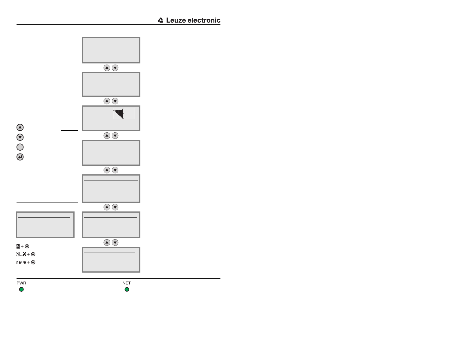
The main menus
ESC
Input of values
12|
<-|0123456789 save
Standard --------- Unit
126 | |
BCL558i SF 102
Leuze electronic
GmbH & Co. KG
SW: V 1.4 HW:1
SN: 0704-081894 001
Network settings
Channel 1:
Addr: 192.168.60.101
Mask: 255.255.255.0
Gateway: 0.0.0.0
IO1 IO2 IO3
IO4 ATT ERR
12345678
Parameter
Parameter handling
Decoder table
Digital SWIO
EtherNet/IP
Language selection
o Deutsch
o English
o Español
o Français
o Italiano
Service
Diagnostics
Status messages
Device information - main menu
Information about
• Device type
• Software version
• Hardware version
• Serial number
Network settings - main menu
• Display of the network settings
See "EtherNet/IP" on page 99.
Bar code reading window - main
menu
Visualization of the read bar code information.
See "Indicators in the display" on page 86.
Parameter - main menu
Configuration of the bar code reader.
See "Parameter menu" on page 92.
Language selection - main menu
Selection of the display language.
See "Language selection menu" on
page 100.
Service - main menu
Scanner diagnosis and status messages.
See "Service menu" on page 100.
PWR LED NET LED
Off Device OFF Off No supply voltage/IP address
Flashes green Device ok, initialization phase Flashes green No Ethernet/IP communication
Green, continuous light Device OK Green, continuous light Bus communication ok
Orange, continuous light Service mode Flashes red Timeout
Flashes red Device ok, warning set Flashes red/green self test
Red, continuous light Device error Red, continuous light double IP address
Actions
o Start decoding
o Start alignment
o Start auto-setup
o Start teach-in
Actions - main menu
Various functions for scanner configuration
and manual operation.
See "Actions menu" on page 101.

Table of contents
1 General information . . . . . . . . . . . . . . . . . . . . . . . . . . . . . . . . . . . . 9
1.1 Explanation of symbols . . . . . . . . . . . . . . . . . . . . . . . . . . . . . . . . . . . . . . . . . . . . . . . . . . . 9
1.2 Declaration of conformity . . . . . . . . . . . . . . . . . . . . . . . . . . . . . . . . . . . . . . . . . . . . . . . . . 9
2 Safety notices. . . . . . . . . . . . . . . . . . . . . . . . . . . . . . . . . . . . . . . . 10
2.1 General safety notices. . . . . . . . . . . . . . . . . . . . . . . . . . . . . . . . . . . . . . . . . . . . . . . . . . . 10
2.2 Safety standards . . . . . . . . . . . . . . . . . . . . . . . . . . . . . . . . . . . . . . . . . . . . . . . . . . . . . . . 10
2.3 Approved purpose. . . . . . . . . . . . . . . . . . . . . . . . . . . . . . . . . . . . . . . . . . . . . . . . . . . . . . 10
2.4 Working safely . . . . . . . . . . . . . . . . . . . . . . . . . . . . . . . . . . . . . . . . . . . . . . . . . . . . . . . . . 11
3 Fast commissioning / operating principle . . . . . . . . . . . . . . . . . . . 13
3.1 Mounting the BCL 558i . . . . . . . . . . . . . . . . . . . . . . . . . . . . . . . . . . . . . . . . . . . . . . . . . . 13
3.2 Device arrangement and selection of the mounting location . . . . . . . . . . . . . . . . . . . . 13
3.3 Electrical connection BCL 558i. . . . . . . . . . . . . . . . . . . . . . . . . . . . . . . . . . . . . . . . . . . . 14
3.4 Starting the device. . . . . . . . . . . . . . . . . . . . . . . . . . . . . . . . . . . . . . . . . . . . . . . . . . . . . . 15
3.5 Further settings . . . . . . . . . . . . . . . . . . . . . . . . . . . . . . . . . . . . . . . . . . . . . . . . . . . . . . . . 18
3.6 Bar code reading . . . . . . . . . . . . . . . . . . . . . . . . . . . . . . . . . . . . . . . . . . . . . . . . . . . . . . . 19
4 Device description . . . . . . . . . . . . . . . . . . . . . . . . . . . . . . . . . . . . 20
4.1 About the bar code readers of the BCL 500i series. . . . . . . . . . . . . . . . . . . . . . . . . . . . 20
4.2 Characteristics of the bar code readers of the BCL 500i series . . . . . . . . . . . . . . . . . . 21
4.3 Device construction. . . . . . . . . . . . . . . . . . . . . . . . . . . . . . . . . . . . . . . . . . . . . . . . . . . . . 23
4.4 Reading techniques. . . . . . . . . . . . . . . . . . . . . . . . . . . . . . . . . . . . . . . . . . . . . . . . . . . . . 24
4.4.1 Line scanner (single line). . . . . . . . . . . . . . . . . . . . . . . . . . . . . . . . . . . . . . . . . . . . . . . . . . 24
4.4.2 Line scanner with oscillating mirror . . . . . . . . . . . . . . . . . . . . . . . . . . . . . . . . . . . . . . . . . 25
4.4.3 Omnidirectional reading . . . . . . . . . . . . . . . . . . . . . . . . . . . . . . . . . . . . . . . . . . . . . . . . . . 26
4.5 Fieldbus systems. . . . . . . . . . . . . . . . . . . . . . . . . . . . . . . . . . . . . . . . . . . . . . . . . . . . . . . 27
4.5.1 EtherNet/IP . . . . . . . . . . . . . . . . . . . . . . . . . . . . . . . . . . . . . . . . . . . . . . . . . . . . . . . . . . . . 27
4.5.2 Ethernet – star topology . . . . . . . . . . . . . . . . . . . . . . . . . . . . . . . . . . . . . . . . . . . . . . . . . . 28
4.5.3 Ethernet – linear topology . . . . . . . . . . . . . . . . . . . . . . . . . . . . . . . . . . . . . . . . . . . . . . . . . 29
4.6 Heater. . . . . . . . . . . . . . . . . . . . . . . . . . . . . . . . . . . . . . . . . . . . . . . . . . . . . . . . . . . . . . . . 30
4.7 External parameter memory . . . . . . . . . . . . . . . . . . . . . . . . . . . . . . . . . . . . . . . . . . . . . . 30
4.8 autoReflAct. . . . . . . . . . . . . . . . . . . . . . . . . . . . . . . . . . . . . . . . . . . . . . . . . . . . . . . . . . . . 31
4.9 Reference codes . . . . . . . . . . . . . . . . . . . . . . . . . . . . . . . . . . . . . . . . . . . . . . . . . . . . . . . 32
4.10 autoConfig . . . . . . . . . . . . . . . . . . . . . . . . . . . . . . . . . . . . . . . . . . . . . . . . . . . . . . . . . . . . 32
5 Specifications . . . . . . . . . . . . . . . . . . . . . . . . . . . . . . . . . . . . . . . . 33
5.1 General specifications of the bar code readers . . . . . . . . . . . . . . . . . . . . . . . . . . . . . . . 33
Leuze electronic BCL 548i 1

Table of contents
5.1.1 Line scanner . . . . . . . . . . . . . . . . . . . . . . . . . . . . . . . . . . . . . . . . . . . . . . . . . . . . . . . . . . . 33
5.1.2 Oscillating-mirror scanner . . . . . . . . . . . . . . . . . . . . . . . . . . . . . . . . . . . . . . . . . . . . . . . . .35
5.1.3 Line scanner with deflection mirror . . . . . . . . . . . . . . . . . . . . . . . . . . . . . . . . . . . . . . . . . . 35
5.2 Heating models of the bar code readers. . . . . . . . . . . . . . . . . . . . . . . . . . . . . . . . . . . . . 36
5.2.1 Line scanner with heating . . . . . . . . . . . . . . . . . . . . . . . . . . . . . . . . . . . . . . . . . . . . . . . . .37
5.2.2 Oscillating-mirror scanner with heating . . . . . . . . . . . . . . . . . . . . . . . . . . . . . . . . . . . . . . . 38
5.2.3 Line scanner with deflection mirror and heating . . . . . . . . . . . . . . . . . . . . . . . . . . . . . . . . 39
5.3 Dimensioned drawings. . . . . . . . . . . . . . . . . . . . . . . . . . . . . . . . . . . . . . . . . . . . . . . . . . . 40
5.3.1 Line scanner with / without heating . . . . . . . . . . . . . . . . . . . . . . . . . . . . . . . . . . . . . . . . . . 40
5.3.2 Deflection mirror scanner with / without heating. . . . . . . . . . . . . . . . . . . . . . . . . . . . . . . . 41
5.3.3 Oscillating-mirror scanner with / without heating . . . . . . . . . . . . . . . . . . . . . . . . . . . . . . . 42
5.4 Type overview BCL 558i. . . . . . . . . . . . . . . . . . . . . . . . . . . . . . . . . . . . . . . . . . . . . . . . . . 43
5.5 Reading field curves / optical data . . . . . . . . . . . . . . . . . . . . . . . . . . . . . . . . . . . . . . . . . 44
5.6 Reading field curves. . . . . . . . . . . . . . . . . . . . . . . . . . . . . . . . . . . . . . . . . . . . . . . . . . . . .45
5.6.1 High Density (N) Optics: BCL 558i SN 100/102 . . . . . . . . . . . . . . . . . . . . . . . . . . . . . . . . 46
5.6.2 High Density (N) Optics: BCL 558i ON 100 . . . . . . . . . . . . . . . . . . . . . . . . . . . . . . . . . . . . 47
5.6.3 Medium Density (M) Optics: BCL 558i SM 100/102 . . . . . . . . . . . . . . . . . . . . . . . . . . . . . 48
5.6.4 Medium Density (M) Optics: BCL 558i OM 100. . . . . . . . . . . . . . . . . . . . . . . . . . . . . . . . . 49
5.6.5 Low Density (F) Optics: BCL 558i SF 100/102 . . . . . . . . . . . . . . . . . . . . . . . . . . . . . . . . . 50
5.6.6 Low Density (F) Optics: BCL 558i OF 100 . . . . . . . . . . . . . . . . . . . . . . . . . . . . . . . . . . . . . 51
5.6.7 Ultra Low Density (L) Optics: BCL 558i SL 102. . . . . . . . . . . . . . . . . . . . . . . . . . . . . . . . . 52
5.6.8 Ultra Low Density (L) Optics: BCL 558i OL 100 . . . . . . . . . . . . . . . . . . . . . . . . . . . . . . . . 53
5.7 Reading field curves for heating devices . . . . . . . . . . . . . . . . . . . . . . . . . . . . . . . . . . . . 54
5.7.1 High Density (N) Optics: BCL 558i SN 102 H . . . . . . . . . . . . . . . . . . . . . . . . . . . . . . . . . . 54
5.7.2 High Density (N) Optics: BCL 558i SN 100 H . . . . . . . . . . . . . . . . . . . . . . . . . . . . . . . . . . 55
5.7.3 High Density (N) Optics: BCL 558i ON 100 H . . . . . . . . . . . . . . . . . . . . . . . . . . . . . . . . . . 56
5.7.4 Medium Density (M) Optics: BCL 558i SM 102 H . . . . . . . . . . . . . . . . . . . . . . . . . . . . . . . 57
5.7.5 Medium Density (M) Optics: BCL 558i SM 100 H . . . . . . . . . . . . . . . . . . . . . . . . . . . . . . . 58
5.7.6 Medium Density (M) Optics: BCL 558i OM 100 H . . . . . . . . . . . . . . . . . . . . . . . . . . . . . . . 59
5.7.7 Low Density (F) Optics: BCL 558i SF 102 H . . . . . . . . . . . . . . . . . . . . . . . . . . . . . . . . . . . 60
5.7.8 Low Density (F) Optics: BCL 558i SF 100 H . . . . . . . . . . . . . . . . . . . . . . . . . . . . . . . . . . . 61
5.7.9 Low Density (F) Optics: BCL 558i OF 100 H . . . . . . . . . . . . . . . . . . . . . . . . . . . . . . . . . . . 62
5.7.10 Ultra Low Density (L) Optics: BCL 558i SL 102 H . . . . . . . . . . . . . . . . . . . . . . . . . . . . . . . 63
5.7.11 Ultra Low Density (L) Optics: BCL 558i OL 100 H . . . . . . . . . . . . . . . . . . . . . . . . . . . . . . . 64
6 Installation and mounting . . . . . . . . . . . . . . . . . . . . . . . . . . . . . . . 65
6.1 Storage, transportation . . . . . . . . . . . . . . . . . . . . . . . . . . . . . . . . . . . . . . . . . . . . . . . . . . 65
6.2 Mounting the BCL 558i . . . . . . . . . . . . . . . . . . . . . . . . . . . . . . . . . . . . . . . . . . . . . . . . . . . 66
6.2.1 Fastening with M4 x 6 screws . . . . . . . . . . . . . . . . . . . . . . . . . . . . . . . . . . . . . . . . . . . . . . 66
6.2.2 BT 56 mounting device . . . . . . . . . . . . . . . . . . . . . . . . . . . . . . . . . . . . . . . . . . . . . . . . . . . 67
6.2.3 BT 59 mounting device . . . . . . . . . . . . . . . . . . . . . . . . . . . . . . . . . . . . . . . . . . . . . . . . . . . 69
2 BCL 548i Leuze electronic

Table of contents
6.3 Device arrangement. . . . . . . . . . . . . . . . . . . . . . . . . . . . . . . . . . . . . . . . . . . . . . . . . . . . . 70
6.3.1 Selecting a mounting location . . . . . . . . . . . . . . . . . . . . . . . . . . . . . . . . . . . . . . . . . . . . . 70
6.3.2 Avoiding total reflection – Line scanner . . . . . . . . . . . . . . . . . . . . . . . . . . . . . . . . . . . . . . 71
6.3.3 Avoiding total reflection – oscillating/deflection-mirror scanner. . . . . . . . . . . . . . . . . . . . 71
6.3.4 Mounting location . . . . . . . . . . . . . . . . . . . . . . . . . . . . . . . . . . . . . . . . . . . . . . . . . . . . . . . 72
6.3.5 Devices with integrated heating . . . . . . . . . . . . . . . . . . . . . . . . . . . . . . . . . . . . . . . . . . . . 72
6.3.6 Possible read angles between BCL 558i and bar code . . . . . . . . . . . . . . . . . . . . . . . . . . 73
6.4 Attaching laser warning sign. . . . . . . . . . . . . . . . . . . . . . . . . . . . . . . . . . . . . . . . . . . . . . 73
6.5 Cleaning . . . . . . . . . . . . . . . . . . . . . . . . . . . . . . . . . . . . . . . . . . . . . . . . . . . . . . . . . . . . . . 73
7 Electrical connection . . . . . . . . . . . . . . . . . . . . . . . . . . . . . . . . . . 74
7.1 Safety notices for the electrical connection. . . . . . . . . . . . . . . . . . . . . . . . . . . . . . . . . . 75
7.2 Electrical connection of the BCL 558i . . . . . . . . . . . . . . . . . . . . . . . . . . . . . . . . . . . . . . 76
7.2.1 PWR – Voltage supply and switching input/outputs 3 and 4 . . . . . . . . . . . . . . . . . . . . . . 77
7.2.2 SERVICE – USB interface (type A) . . . . . . . . . . . . . . . . . . . . . . . . . . . . . . . . . . . . . . . . . . 79
7.2.3 SW IN/OUT – Switching input/switching output. . . . . . . . . . . . . . . . . . . . . . . . . . . . . . . . 80
7.2.4 HOST / BUS IN for BCL 558i . . . . . . . . . . . . . . . . . . . . . . . . . . . . . . . . . . . . . . . . . . . . . . 82
7.2.5 BUS OUT for the BCL 558i . . . . . . . . . . . . . . . . . . . . . . . . . . . . . . . . . . . . . . . . . . . . . . . . 83
7.3 Ethernet topologies . . . . . . . . . . . . . . . . . . . . . . . . . . . . . . . . . . . . . . . . . . . . . . . . . . . . . 84
7.3.1 Ethernet wiring . . . . . . . . . . . . . . . . . . . . . . . . . . . . . . . . . . . . . . . . . . . . . . . . . . . . . . . . . 85
7.4 Cable lengths and shielding . . . . . . . . . . . . . . . . . . . . . . . . . . . . . . . . . . . . . . . . . . . . . . 85
8 Display and control panel . . . . . . . . . . . . . . . . . . . . . . . . . . . . . . . 86
8.1 Structure of the control panel . . . . . . . . . . . . . . . . . . . . . . . . . . . . . . . . . . . . . . . . . . . . . 86
8.2 Status display and operation . . . . . . . . . . . . . . . . . . . . . . . . . . . . . . . . . . . . . . . . . . . . . 86
8.2.1 Indicators in the display . . . . . . . . . . . . . . . . . . . . . . . . . . . . . . . . . . . . . . . . . . . . . . . . . . 86
8.2.2 LED status indicators . . . . . . . . . . . . . . . . . . . . . . . . . . . . . . . . . . . . . . . . . . . . . . . . . . . . 87
8.2.3 Control buttons . . . . . . . . . . . . . . . . . . . . . . . . . . . . . . . . . . . . . . . . . . . . . . . . . . . . . . . . . 88
8.3 Menu description. . . . . . . . . . . . . . . . . . . . . . . . . . . . . . . . . . . . . . . . . . . . . . . . . . . . . . . 90
8.3.1 The main menus . . . . . . . . . . . . . . . . . . . . . . . . . . . . . . . . . . . . . . . . . . . . . . . . . . . . . . . . 90
8.3.2 Parameter menu . . . . . . . . . . . . . . . . . . . . . . . . . . . . . . . . . . . . . . . . . . . . . . . . . . . . . . . . 92
8.3.3 Language selection menu. . . . . . . . . . . . . . . . . . . . . . . . . . . . . . . . . . . . . . . . . . . . . . . . 100
8.3.4 Service menu . . . . . . . . . . . . . . . . . . . . . . . . . . . . . . . . . . . . . . . . . . . . . . . . . . . . . . . . . 100
8.3.5 Actions menu . . . . . . . . . . . . . . . . . . . . . . . . . . . . . . . . . . . . . . . . . . . . . . . . . . . . . . . . . 101
8.4 Operation . . . . . . . . . . . . . . . . . . . . . . . . . . . . . . . . . . . . . . . . . . . . . . . . . . . . . . . . . . . . 103
9 Leuze webConfig tool . . . . . . . . . . . . . . . . . . . . . . . . . . . . . . . . . 104
9.1 Connecting the SERVICE USB interface. . . . . . . . . . . . . . . . . . . . . . . . . . . . . . . . . . . . 104
9.2 Installing the required software. . . . . . . . . . . . . . . . . . . . . . . . . . . . . . . . . . . . . . . . . . . 105
9.2.1 System requirements . . . . . . . . . . . . . . . . . . . . . . . . . . . . . . . . . . . . . . . . . . . . . . . . . . . 105
9.2.2 Installing the USB driver . . . . . . . . . . . . . . . . . . . . . . . . . . . . . . . . . . . . . . . . . . . . . . . . . 105
Leuze electronic BCL 548i 3

Table of contents
9.3 Starting the webConfig tool . . . . . . . . . . . . . . . . . . . . . . . . . . . . . . . . . . . . . . . . . . . . . . 107
9.4 Short description of the webConfig tool . . . . . . . . . . . . . . . . . . . . . . . . . . . . . . . . . . . . 108
9.4.1 Module overview in the Configuration menu . . . . . . . . . . . . . . . . . . . . . . . . . . . . . . . . . . 108
10 Commissioning and configuration . . . . . . . . . . . . . . . . . . . . . . . . 110
10.1 Measures to be performed prior to the initial commissioning . . . . . . . . . . . . . . . . . . .111
10.2 Starting the device . . . . . . . . . . . . . . . . . . . . . . . . . . . . . . . . . . . . . . . . . . . . . . . . . . . . . 112
10.3 Setting the communication parameters . . . . . . . . . . . . . . . . . . . . . . . . . . . . . . . . . . . . 112
10.3.1 Manually setting the IP address . . . . . . . . . . . . . . . . . . . . . . . . . . . . . . . . . . . . . . . . . . . 113
10.4 Configuration steps for a Rockwell control without EDS support . . . . . . . . . . . . . . . . 115
10.4.1 Integrating the hardware into the PLC using the generic Ethernet module. . . . . . . . . . . 115
10.5 Configuration steps for a Rockwell control with EDS support . . . . . . . . . . . . . . . . . . . 116
10.5.1 Integrating the hardware into the PLC and installing the EDS file . . . . . . . . . . . . . . . . . . 116
10.6 EDS file - general info . . . . . . . . . . . . . . . . . . . . . . . . . . . . . . . . . . . . . . . . . . . . . . . . . . . 117
10.7 Detailed EDS description . . . . . . . . . . . . . . . . . . . . . . . . . . . . . . . . . . . . . . . . . . . . . . . . 117
10.7.1 Class 1 - Identity object . . . . . . . . . . . . . . . . . . . . . . . . . . . . . . . . . . . . . . . . . . . . . . . . . . 117
10.7.2 Class 4 - Assembly . . . . . . . . . . . . . . . . . . . . . . . . . . . . . . . . . . . . . . . . . . . . . . . . . . . . . 119
10.7.2.1 Input assembly...........................................................................................................................119
10.7.2.2 Output assembly........................................................................................................................122
10.7.2.3 Configuration assembly .............................................................................................................125
10.7.3 Class 103 - I/O status and control. . . . . . . . . . . . . . . . . . . . . . . . . . . . . . . . . . . . . . . . . . 126
10.7.4 Class 106 - Activation . . . . . . . . . . . . . . . . . . . . . . . . . . . . . . . . . . . . . . . . . . . . . . . . . . . 128
10.7.5 Class 107 - Result data . . . . . . . . . . . . . . . . . . . . . . . . . . . . . . . . . . . . . . . . . . . . . . . . . 130
10.7.6 Class 108 - Entry data . . . . . . . . . . . . . . . . . . . . . . . . . . . . . . . . . . . . . . . . . . . . . . . . . . . 132
10.7.7 Class 109 - Device status and device control . . . . . . . . . . . . . . . . . . . . . . . . . . . . . . . . . 135
10.8 Configuration example . . . . . . . . . . . . . . . . . . . . . . . . . . . . . . . . . . . . . . . . . . . . . . . . . . 136
10.8.1 Example 1 - activation & result . . . . . . . . . . . . . . . . . . . . . . . . . . . . . . . . . . . . . . . . . . . . 137
10.8.2 Example 2 - activation & result & I/Os . . . . . . . . . . . . . . . . . . . . . . . . . . . . . . . . . . . . . . . 140
10.8.3 Example 3 - activation & fragmented result. . . . . . . . . . . . . . . . . . . . . . . . . . . . . . . . . . . 143
10.8.4 Example 4 - entry data & result . . . . . . . . . . . . . . . . . . . . . . . . . . . . . . . . . . . . . . . . . . . . 146
10.9 Additional settings for the BCL 558i . . . . . . . . . . . . . . . . . . . . . . . . . . . . . . . . . . . . . . . 149
10.9.1 Decoding and processing the read data . . . . . . . . . . . . . . . . . . . . . . . . . . . . . . . . . . . . . 149
10.9.2 Control of the decoding . . . . . . . . . . . . . . . . . . . . . . . . . . . . . . . . . . . . . . . . . . . . . . . . . . 150
10.9.3 Control of the switching outputs . . . . . . . . . . . . . . . . . . . . . . . . . . . . . . . . . . . . . . . . . . . 151
10.10 Transmitting configuration data. . . . . . . . . . . . . . . . . . . . . . . . . . . . . . . . . . . . . . . . . . . 152
10.10.1 Via the webConfig tool. . . . . . . . . . . . . . . . . . . . . . . . . . . . . . . . . . . . . . . . . . . . . . . . . . . 152
10.10.2 With the external parameter memory . . . . . . . . . . . . . . . . . . . . . . . . . . . . . . . . . . . . . . . 152
11 Online commands . . . . . . . . . . . . . . . . . . . . . . . . . . . . . . . . . . . . 155
11.1 Overview of commands and parameters. . . . . . . . . . . . . . . . . . . . . . . . . . . . . . . . . . . . 155
11.1.1 General 'online' commands . . . . . . . . . . . . . . . . . . . . . . . . . . . . . . . . . . . . . . . . . . . . . . . 156
4 BCL 548i Leuze electronic

Table of contents
11.1.2 ’Online’ commands for system control. . . . . . . . . . . . . . . . . . . . . . . . . . . . . . . . . . . . . . 163
11.1.3 ’Online’ commands for configuration of switching inputs/outputs . . . . . . . . . . . . . . . . . 164
11.1.4 ’Online’ commands for the parameter set operations . . . . . . . . . . . . . . . . . . . . . . . . . . 167
12 Diagnostics and troubleshooting . . . . . . . . . . . . . . . . . . . . . . . . 173
12.1 General causes of errors . . . . . . . . . . . . . . . . . . . . . . . . . . . . . . . . . . . . . . . . . . . . . . . . 173
12.2 Interface errors. . . . . . . . . . . . . . . . . . . . . . . . . . . . . . . . . . . . . . . . . . . . . . . . . . . . . . . . 173
13 Type overview and accessories . . . . . . . . . . . . . . . . . . . . . . . . . 175
13.1 Type key . . . . . . . . . . . . . . . . . . . . . . . . . . . . . . . . . . . . . . . . . . . . . . . . . . . . . . . . . . . . . 175
13.2 Type overview BCL 558i . . . . . . . . . . . . . . . . . . . . . . . . . . . . . . . . . . . . . . . . . . . . . . . . 176
13.3 Accessory connectors . . . . . . . . . . . . . . . . . . . . . . . . . . . . . . . . . . . . . . . . . . . . . . . . . . 177
13.4 Accessory USB cable . . . . . . . . . . . . . . . . . . . . . . . . . . . . . . . . . . . . . . . . . . . . . . . . . . 177
13.5 Accessory external parameter memory . . . . . . . . . . . . . . . . . . . . . . . . . . . . . . . . . . . . 177
13.6 Accessory mounting device . . . . . . . . . . . . . . . . . . . . . . . . . . . . . . . . . . . . . . . . . . . . . 177
13.7 Accessory reflector for AutoReflAct . . . . . . . . . . . . . . . . . . . . . . . . . . . . . . . . . . . . . . . 178
13.8 Accessory ready-made cables for voltage supply . . . . . . . . . . . . . . . . . . . . . . . . . . . . 178
13.8.1 Contact assignment of PWR connection cable . . . . . . . . . . . . . . . . . . . . . . . . . . . . . . . 178
13.8.2 Specifications of the cables for voltage supply . . . . . . . . . . . . . . . . . . . . . . . . . . . . . . . 178
13.8.3 Order codes of the cables for voltage supply. . . . . . . . . . . . . . . . . . . . . . . . . . . . . . . . . 178
13.9 Accessory ready-made cables for bus connection . . . . . . . . . . . . . . . . . . . . . . . . . . . 179
13.9.1 General information . . . . . . . . . . . . . . . . . . . . . . . . . . . . . . . . . . . . . . . . . . . . . . . . . . . . 179
13.9.2 Contact assignments M12 Ethernet connection cables KB ET… . . . . . . . . . . . . . . . . . 179
13.9.3 Specifications of the M 12 Ethernet connection cables KB ET… . . . . . . . . . . . . . . . . . . 179
13.9.4 Order codes for M 12 Ethernet connection cables KB ET…. . . . . . . . . . . . . . . . . . . . . . 180
14 Maintenance . . . . . . . . . . . . . . . . . . . . . . . . . . . . . . . . . . . . . . . . 181
14.1 General maintenance information . . . . . . . . . . . . . . . . . . . . . . . . . . . . . . . . . . . . . . . . . 181
14.2 Repairs, servicing . . . . . . . . . . . . . . . . . . . . . . . . . . . . . . . . . . . . . . . . . . . . . . . . . . . . . 181
14.3 Disassembling, packing, disposing . . . . . . . . . . . . . . . . . . . . . . . . . . . . . . . . . . . . . . . 181
15 Appendix. . . . . . . . . . . . . . . . . . . . . . . . . . . . . . . . . . . . . . . . . . . 182
15.1 Declaration of conformity . . . . . . . . . . . . . . . . . . . . . . . . . . . . . . . . . . . . . . . . . . . . . . . 182
15.2 ASCII character set . . . . . . . . . . . . . . . . . . . . . . . . . . . . . . . . . . . . . . . . . . . . . . . . . . . . 183
15.3 Bar code samples . . . . . . . . . . . . . . . . . . . . . . . . . . . . . . . . . . . . . . . . . . . . . . . . . . . . . 187
15.3.1 Module 0.3 . . . . . . . . . . . . . . . . . . . . . . . . . . . . . . . . . . . . . . . . . . . . . . . . . . . . . . . . . . . 187
15.3.2 Module 0.5 . . . . . . . . . . . . . . . . . . . . . . . . . . . . . . . . . . . . . . . . . . . . . . . . . . . . . . . . . . . 188
Leuze electronic BCL 548i 5

Figures and tables
Figure 2.1: Attachment of the stick-on labels with warning notices at the BCL 558i................................ 12
Figure 3.1: Connections of the BCL 558i................................................................................................. 14
Figure 3.2: Manually setting the IP address ............................................................................................ 16
Figure 3.3: Generic Ethernet module....................................................................................................... 17
Figure 4.1: Line scanner, line scanner with deflection mirror and oscillating-mirror scanner................... 20
Figure 4.2: Possible bar code orientation ................................................................................................ 22
Figure 4.3: Device construction .............................................................................................................. 23
Figure 4.4: Deflection principle for the line scanner ................................................................................ 24
Figure 4.5: Deflection principle for the line scanner with oscillating mirror add-on.................................. 25
Figure 4.6: Principle arrangement for omnidirectional reading ................................................................ 26
Figure 4.7: Ethernet with star topology ................................................................................................... 28
Figure 4.8: Ethernet with linear topology................................................................................................. 29
Figure 4.9: External parameter memory.................................................................................................. 30
Figure 4.10: Reflector arrangement for autoReflAct .................................................................................. 31
Table 5.1: Specifications of the BCL 558i line scanners without heating................................................ 33
Table 5.2: Specifications of the BCL 558i oscillating-mirror scanners without heating........................... 35
Table 5.3: Specifications of the BCL 558i deflection mirror scanners without heating............................ 36
Table 5.4: Specifications of the BCL 558i line scanners with heating..................................................... 37
Table 5.5: Specifications of the BCL 558i oscillating-mirror scanners with heating................................ 38
Table 5.6: Specifications of the BCL 558i deflection mirror scanners with heating................................. 39
Figure 5.1: Dimensioned drawing BCL 558i line scanner S…102 ........................................................... 40
Figure 5.2: Dimensioned drawing BCL 558i deflection-mirror scanner S…100....................................... 41
Figure 5.3: Dimensioned drawing BCL 558i oscillating-mirror scanner O…100 ...................................... 42
Table 5.7: Type overview BCL 558i ....................................................................................................... 43
Figure 5.4: The most important characteristics of a bar code .................................................................. 44
Figure 5.5: Zero position of the reading distance .................................................................................... 45
Table 5.8: Reading conditions ............................................................................................................... 45
Figure 5.6: "High Density" reading field curve for line scanner (with/without deflection mirror)............... 46
Figure 5.7: "High Density" reading field curve for oscillating-mirror scanners......................................... 47
Figure 5.8: Lateral "High Density" reading field curve for oscillating-mirror scanners ............................. 47
Figure 5.9: "Medium Density" reading field curve for line scanner (with/without deflection mirror) ......... 48
Figure 5.10: "Medium Density" reading field curve for oscillating-mirror scanners ................................... 49
Figure 5.11: Lateral "Medium Density" reading field curve for oscillating-mirror scanners........................ 49
Figure 5.12: "Low Density" reading field curve for line scanner (with/without deflection mirror) ............... 50
Figure 5.13: "Low Density" reading field curve for oscillating-mirror scanners ......................................... 51
Figure 5.14: Lateral "Low Density" reading field curve for oscillating-mirror scanners.............................. 51
Figure 5.15: "Ultra Low Density" reading field curve for line scanner without deflection mirror................. 52
Figure 5.16: "Ultra Low Density" reading field curve for oscillating-mirror scanners ................................. 53
Figure 5.17: Lateral "Ultra Low Density" reading field curve for oscillating-mirror scanners...................... 53
Figure 5.18: "High Density" reading field curve for line scanner with heating (without deflection mirror) .. 54
Figure 5.19: "High Density" reading field curve for line scanner with heating (with deflection mirror) ....... 55
Figure 5.20: "High Density" reading field curve for oscillating-mirror scanners with heating..................... 56
Figure 5.21: Lateral "High Density" reading field curve for oscillating-mirror scanners with heating ......... 56
Figure 5.22: "Medium Density" reading field curve for line scanner with heating (without deflection mirror) ... 57
Figure 5.23: "Medium Density" reading field curve for line scanner with heating (with deflection mirror).. 58
Figure 5.24: "Medium Density" reading field curve for oscillating-mirror scanners with heating ............... 59
Figure 5.25: Lateral "Medium Density" reading field curve for oscillating-mirror scanners with heating.... 59
Figure 5.26: "Low Density" reading field curve for line scanner with heating (without deflection mirror)... 60
6 BCL 558i Leuze electronic

Figures and tables
Figure 5.27: "Low Density" reading field curve for line scanner with heating (with deflection mirror) ........61
Figure 5.28: "Low Density" reading field curve for oscillating-mirror scanners with heating...................... 62
Figure 5.29: Lateral "Low Density" reading field curve for oscillating-mirror scanners with heating.......... 62
Figure 5.30: "Ultra Low Density" reading field curve for line scanner with heating (without deflection mirror). 63
Figure 5.31: "Ultra Low Density" reading field curve for oscillating-mirror scanners with heating .............64
Figure 5.32: Lateral "Ultra Low Density" reading field curve for oscillating-mirror scanners with heating.. 64
Figure 6.1: Device name plate BCL 558i ................................................................................................. 65
Figure 6.2: Fastening options using M 4x6 threaded holes....................................................................... 66
Figure 6.3: BT 56 mounting device ......................................................................................................... 67
Figure 6.4: Mounting example of BCL 558i with BT 56............................................................................68
Figure 6.5: BT 59 mounting device ......................................................................................................... 69
Figure 6.6: Total reflection – line scanner ...............................................................................................71
Figure 6.7: Total reflection – BCL 558i with oscillating/deflection mirror .................................................72
Figure 6.8: Reading angle for the line scanner ........................................................................................73
Figure 7.1: Location of the electrical connections.................................................................................... 74
Figure 7.2: Connections of the BCL 558i ................................................................................................. 76
Table 7.1: Pin assignment PWR ............................................................................................................. 77
Figure 7.3: Switching input connection diagram SWIO_3 and SWIO_4 ....................................................78
Figure 7.4: Switching output connection diagram SWIO_3 / SWIO_4....................................................... 78
Table 7.2: Pin assignments of SERVICE – USB interface......................................................................... 79
Table 7.3: Pin assignment SW IN/OUT ................................................................................................... 80
Figure 7.5: Switching input connection diagram SWIO_1 and SWIO_2 ....................................................80
Figure 7.6: Switching output connection diagram SWIO_1 / SWIO_2....................................................... 81
Table 7.4: Pin assignment HOST / BUS IN BCL 558i............................................................................... 82
Figure 7.7: HOST / BUS IN cable assignments on RJ-45..........................................................................82
Table 7.5: Pin assignment BUS OUT ......................................................................................................83
Figure 7.8: Ethernet with star topology.................................................................................................... 84
Figure 7.9: Ethernet with linear topology ................................................................................................. 84
Table 7.6: Cable lengths and shielding ..................................................................................................85
Figure 8.1: Structure of the control panel ................................................................................................ 86
Table 8.1: Parameter handling submenu ...............................................................................................92
Table 8.2: Decoder table submenu ........................................................................................................93
Table 8.3: Digital SWIO submenu........................................................................................................... 96
Table 8.4: EtherNet/IP submenu ............................................................................................................99
Figure 9.1: Connecting the SERVICE USB interface ................................................................................104
Figure 9.2: Device Manager with connected BCL 558i .......................................................................... 106
Figure 9.3: The start page of the webConfig tool ................................................................................... 107
Figure 9.4: Module overview in the webConfig tool ............................................................................... 108
Figure 10.1: Connections of the BCL 558i ............................................................................................... 111
Figure 10.2: Manually setting the IP address........................................................................................... 113
Figure 10.3: Generic Ethernet module.....................................................................................................115
Figure 10.4: New module........................................................................................................................ 116
Figure 10.5: Connection between Data acceptance/Data rejection/Error code attributes.......................... 133
Figure 10.6: Configuration of example 1 - module definition with generic module...................................137
Figure 10.7: Configuration of example 1 - module definition with the EDS file .........................................137
Figure 10.8: Data exchange sequence diagram - example 1 ................................................................... 139
Figure 10.9: Configuration of example 2 - module definition with generic module...................................140
Figure 10.10: Configuration of example 2 - module definition with the EDS file.........................................140
Leuze electronic BCL 558i 7

Figures and tables
Figure 10.11: Data exchange sequence diagram - example 2................................................................... 142
Figure 10.12: Configuration of example 3 - module definition with generic module................................... 143
Figure 10.13: Configuration of example 3 - module definition with the EDS file......................................... 143
Figure 10.14: Data exchange sequence diagram - example 3................................................................... 145
Figure 10.15: Configuration of example 4 - module definition with generic module................................... 146
Figure 10.16: Configuration of example 4 - module definition with the EDS file......................................... 146
Figure 10.17: Data exchange sequence diagram - example 4................................................................... 148
Figure 10.18: Storing configuration data in the webConfig tool ................................................................. 152
Figure 10.19: Installing the external parameter memory ........................................................................... 153
Figure 10.20: BCL 558i with installed parameter memory ........................................................................ 153
Table 12.1: General causes of errors ..................................................................................................... 173
Table 12.2: Interface error..................................................................................................................... 173
Table 13.1: Type key ............................................................................................................................. 175
Table 13.2: Type overview BCL 558i ..................................................................................................... 176
Table 13.3: Connectors for the BCL 558i ............................................................................................... 177
Table 13.4: Cable for the BCL 558i........................................................................................................ 177
Table 13.5: External parameter memory for the BCL 558i ..................................................................... 177
Table 13.6: Mounting devices for the BCL 558i ..................................................................................... 177
Table 13.7: Reflector for the BCL 558i................................................................................................... 178
Table 13.8: PWR cables for the BCL 558i .............................................................................................. 178
Figure 13.1: Cable structure of Industrial Ethernet connection cable ....................................................... 179
Table 13.9: Bus connection cables for the BCL 558i .............................................................................. 180
Figure 15.1: Bar code sample labels (module 0.3) .................................................................................. 187
Figure 15.2: Bar code sample labels (module 0.5) .................................................................................. 188
8 BCL 558i Leuze electronic
1 General information
U
L
US
C
LISTED
1.1 Explanation of symbols
The symbols used in this technical description are explained below.
Attention!
This symbol precedes text messages which must strictly be observed. Failure to comply with
this information results in injuries to personnel or damage to the equipment.
Attention Laser!
This symbol warns of possible danger caused by hazardous laser radiation.
Notice!
This symbol indicates text passages containing important information.
1.2 Declaration of conformity
The bar code readers of the BCL 500i series have been developed and manufactured in
accordance with the applicable European standards and directives.
The BCL 500i series is "UL LISTED" according to American and Canadian safety standards,
and fulfills the requirements of Underwriter Laboratories Inc. (UL).
Notice!
You can find the Declaration of Conformity of the devices in the appendix of the manual on
page 182.
The manufacturer of the product, Leuze electronic GmbH & Co. KG in D-73277 Owen,
possesses a certified quality assurance system in accordance with ISO 9001.
Leuze electronic BCL 558i 9
TNT 35/7-24V
2 Safety notices
2.1 General safety notices
Documentation
All entries in this technical description must be heeded, in particular the present chapter
"Safety notices". Keep this technical description in a safe place. It should be available at all
times.
Safety regulations
Observe the locally applicable regulations and the rules of the employer's liability insurance
association.
Repair
Repairs must only be carried out by the manufacturer or an authorized representative.
2.2 Safety standards
The bar code readers of the BCL 500i series were developed, manufactured and tested in
accordance with the applicable safety standards. They correspond to the state of the art.
2.3 Approved purpose
Attention!
The protection of personnel and the device cannot be guaranteed if the device is operated
in a manner not complying with its intended use.
Bar code readers of the BCL 500i series are conceived as stationary, high-speed scanners
with integrated decoders for all current bar codes used for automatic object detection.
In particular, unauthorized uses include:
• In rooms with explosive atmospheres
• Operation for medical purposes
Areas of application
The bar code readers of the BCL 500i series are especially designed for the following areas
of application:
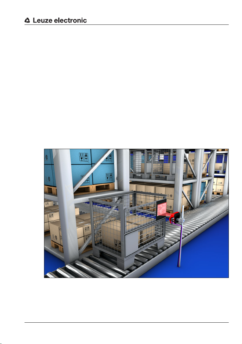
• Storage and conveying technologies, in particular for object identification on fastmoving conveyor belts
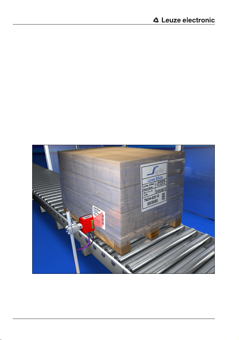
• Pallet transportation applications
• Automobile sector
• Omnidirectional reading
10 BCL 558i Leuze electronic
2.4 Working safely
Attention!
Access to or changes on the device, except where expressly described in this operating
manual, are not authorized.
Safety regulations
Observe the locally applicable legal regulations and the rules of the employer's liability
insurance association.
Qualified personnel
Mounting, commissioning and maintenance of the device must only be carried out by
qualified personnel.
Electrical work must be carried out by a certified electrician.
Attention, laser radiation!
If you look into the beam path over a longer time period, the retina of your eye may
be damaged!
Never look directly into the beam path!
Do not point the laser beam of the BCL 558i at persons!
When mounting and aligning the BCL 558i, avoid reflections of the laser beam off
reflective surfaces!
The BCL 558i bar code readers comply with safety standards EN 60825-1 for a class
2 product. They also comply with the U.S. 21 CFR 1040.10 regulations for a class II
laser product except for deviations pursuant to Laser Notice No. 50, dated July 26,
2001.
Radiant Energy: The BCL 558i uses a low power visible laser diode. The emitted wavelength is 655nm. The average laser power is less than 1mW in accordance with the
definition of class 2 lasers.
Adjustments: Do not attempt any adjustments to or alterations of this product.
Do not remove the protective housing of the bar code reader. There are no userserviceable parts inside.
The scanner window is the only aperture through which light may be observed on this
product. A failure of the scanner motor, while the laser diode continues to emit a laser
beam, may cause emission levels to exceed those for safe operation. The bar code
reader has safeguards to prevent this occurrence. If, however, a stationary beam is
emitted, the failing bar code reader should be disconnected from its power source
immediately.
TNT 35/7-24V
CAUTION: Use of controls or adjustments or performance of procedures other than
specified herein may result in hazardous light exposure.
Leuze electronic BCL 558i 11
The use of optical instruments or devices in combination with the device increases
A
B
BCL 558i
Line scanner
BCL 558i
with oscillating/deflection mirror
C
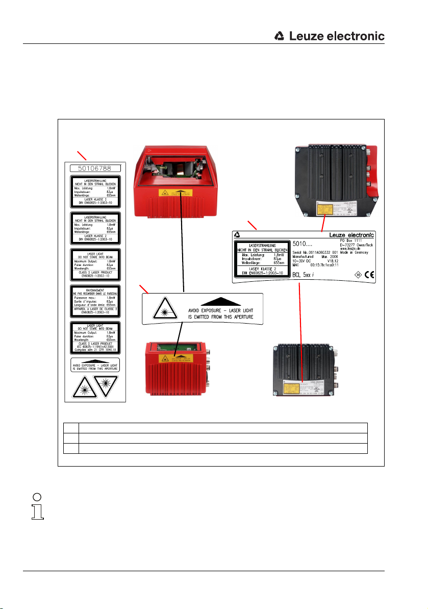
A Included stick-on labels
B Aperture label
C Name plate
the danger of eye damage!
The housing of the BCL 558i is provided with warning notices B and C above and next
to the reading window as shown in the following figure:
Figure 2.1: Attachment of the stick-on labels with warning notices at the BCL 558i
Notice!
It is important that you attach the stick-on labels supplied to the device (A in figure 2.1)! If
the signs would be covered due to the installation situation of the BCL 558i, attach them
instead in the immediate vicinity of the BCL 558i in such a way that it is not necessary to
look into the laser beam when reading the notices.
12 BCL 558i Leuze electronic
3 Fast commissioning / operating principle
Below you will find a short description for the initial commissioning of the BCL 558i. Detailed
explanations for all listed points can be found throughout this technical description.
3.1 Mounting the BCL 558i
The BCL 558i bar code readers can be mounted in 3 different ways:
• Using two M4x6 screws on the rear of the device or using four M4x6 screws on the
bottom of the device.
• Using a BT 56 mounting device on the two fastening grooves.
3.2 Device arrangement and selection of the mounting location
In order to select the right mounting location, several factors must be considered:
• Size, orientation, and position tolerance of the bar codes on the objects to be
scanned.
• The reading field of the BCL 558i in relation to the bar code module width.
• The resulting minimum and maximum reading distance from the respective reading
field (see chapter 5.5 "Reading field curves / optical data").
• The permissible cable lengths between the BCL 558i and the host system depending
on which interface is used.
• The correct time for data output. The BCL 558i should be positioned in such a way
that, taking into consideration the time required for data processing and the conveyor
belt speed, there is sufficient time to e.g. initiate sorting operations on the basis of the
read data.
• The display and control panel should be very visible and accessible.
• For configuring and commissioning with the webConfig tool, the USB interface should
be easily accessible.
For specific information, please refer to chapter 4.4.
Notice!
The beam exits the BCL 558i as follows for the respective devices:
- line scanner parallel to the housing base
- oscillating mirror and deflection mirror perpendicular to the housing base
The black areas in figure 6.1 are the housing base. The best read results are obtained when:
• The BCL 558i is mounted in such a way that the scanning beam is incident on the bar
code at an angle of inclination greater than ±10° … 15° to vertical.
• The reading distance lies in the middle area of the reading field.
• The bar code labels are of good print quality and have good contrast ratios.
• You do not use high-gloss labels.
• There is no direct sunlight.
Leuze electronic BCL 558i 13
TNT 35/7-24V
3.3 Electrical connection BCL 558i
SW IN/OUT
VOUT
1
2
3
4
SWIO_1
SWIO_2
GND
FE
5
HOST / BUS IN
TD+
1
2
3
4
RD+
RD-
TD-
SERVICE
2134
GND D+ D-
U
B
PWR
SWIO_4
SWIO_3
3
2
1
4
5
GND VIN
FE
BUS OUT
TD+
1
2
3
4
RD+
RD-
TD-
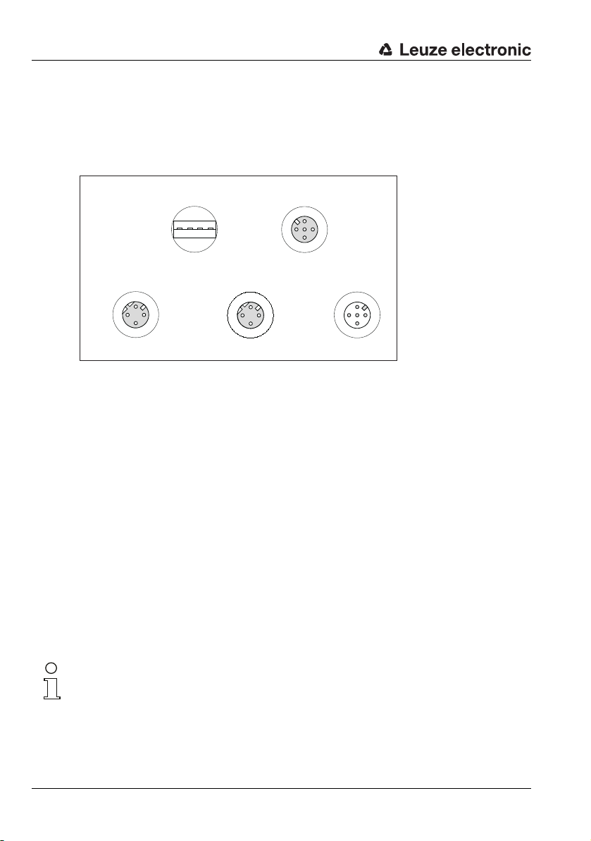
USB socket
Type A
M12 socket
(A-coded)
M12 socket
(D-coded)
M12 socket
(D-coded)
M12 plug
(A-coded)
The BCL 558i is equipped with four M 12 plugs/sockets which are A- and D-coded, and an
USB socket of Type A.
Figure 3.1: Connections of the BCL 558i
Voltage supply and switching inputs/outputs
The voltage supply (10 … 30 VDC) is connected at the PWR M12 connector.
Available at both the PWR M12 connector as well as at the SW IN/OUT M12 socket are
four freely programmable switching inputs/outputs for custom adaptation to the respective application. Detailed information on this topic can be found in chapter 7.2.
Standalone operation in Ethernet network
During stand-alone operation of the BCL 558i, the host interface of the superior system is
connected to HOST/BUS IN. Thus, a star structure (Ethernet structure) is possible. Please
be certain to select the correct protocol for the connected components.
Network operation in Ethernet network
In network operation, the superior system (PC/PLC) is connected to the host interface of
the BCL 558i. With the aid of the "switch" integrated in the BCL 558i, the bus connection
to the next participant, e.g. another BCL 558i, can occur directly via the BUS OUT socket!
Notice!
The BCL 558i does not have its own built-in DHCP server. Please make certain that each
participant in the Ethernet has its own unique IP address. This can be set by a DHCP server
in the primary system or through manual address assignment.
14 BCL 558i Leuze electronic
3.4 Starting the device
Connect the supply voltage +10 … 30VDC (typ. +24 VDC); the BCL 558i starts up and
the bar code reading window appears on the display:
As a first step, you need to set the communication parameters of the BCL 558i.
You can make the necessary settings via the display or via the webConfig tool. Provided
here is only a brief description of the settings via the webConfig tool; detailed information
can be found in chapter 10.
ENIP
3.4.1 BCL 558i on EtherNet/IP
Commissioning on the EtherNet/IP is performed according to the following scheme:
1. Address assignment
• automatic via DHCP, BootP or
• manual via webConfig (with a USB connection)
2. Configuration of the participant depending on the version of the control software:
• either with the generic Ethernet module or
• installation of the EDS file
3. Transferring the data to the control
4. Adapting the device parameters via webConfig
5. Use explicit messaging services
Notice!
On delivery, the automatic address assignment via DHCP server is defined as the standard
setting of the BCL 558i and the IP address is set to 0.0.0.0.
The BCL 558i can be configured in the planning tool/control using the EDS file (Electronic
Data Sheet) if the control supports this. PLC software RSLogix 5000 from Rockwell offers
EDS support for EtherNet/IP from software version 20.00 and up.
Without PLC support of the EDS integration, the settings are made via the generic Ethernet
module. In this case, the respective configuration must be entered and adapted manually
for each device. The parameter download from the control to the BCL 558i is performed
during every establishment of connection. Since the parameters are stored centrally in the
control, this helps during device exchange.
By default, parameter enabling is deactivated and you
cannot change any settings. If you wish to carry out the
configuration via the display, you must activate parameter
enabling. Further information can be found in chapter
"Parameter enabling" on page 103.
TNT 35/7-24V
Leuze electronic BCL 558i 15
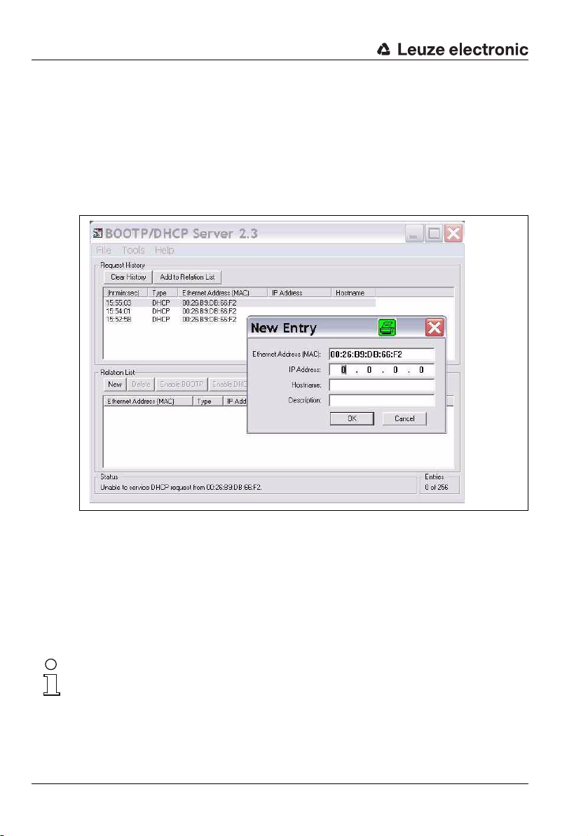
3.4.2 Manually setting the IP address
If your system does not include a DHCP server or if the IP addresses of the devices are to
be set permanently, proceed as follows:
• Have the network administrator specify the data for IP address, net mask and gateway address of the BCL 558i.
• Set the IP address manually via the BootP/DHCP server tool and deactivate the
DHCP operation in the BCL 558i. The BCL 558i automatically adopts these settings.
A restart is not required.
Figure 3.2: Manually setting the IP address
Alternatively, you can set the IP address manually via the webConfig tool. Proceed as
follows:
• Have the network administrator specify the data for IP address, net mask and
gateway address of the BCL 558i.
• Connect the BCL 558i to your computer using the service cable.
• Set these values on the BCL 558i. Via webConfig:
Configuration -> Communication -> Ethernet interface.
Notice!
If the IP address is set via the webConfig tool, then it becomes active after transfer to the
device. A restart is not required.
16 BCL 558i Leuze electronic
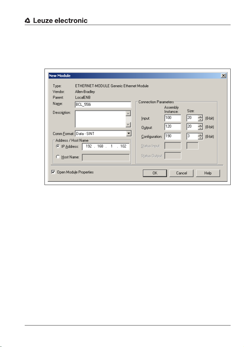
3.4.3 Configure the participant
Configuration with the generic Ethernet module
In the RSLogix 5000 configuration tool (up to software version 20.00), a so-called generic
Ethernet module is created under the Communication path for the BCL 558i.
Figure 3.3: Generic Ethernet module
The input mask for the generic module describes the following parameters to be set:
• The name of the participant (can be selected freely; e.g. BCL 558i)
• The format of I/O data (data - SINT = 8 bits)
• The IP address of the participant
• The address and length of the input assembly (instance 100, instance 101 or instance
102; min 1 byte - up to max. 266 bytes for the default input assembly of the read
results)
• The address and length of the output assembly (instance 120, instance 121 or
instance 122; min 1 byte - up to max. 263 bytes for the default output assembly)
• The address and length of the configuration assembly (instance 190; 3 bytes)
For the exact description of the assemblies for input/output and configuration, please refer
to chapter 10.
TNT 35/7-24V
Leuze electronic BCL 558i 17
Configuration of the participant using the EDS file
From software version 20.00 and up, proceed as follows in the RSLogix 5000 configuration
tool to create the BCL 558i as an EtherNet/IP participant in your system:
• First, load the EDS file for the device via EDS wizard into the PLC database.
Notice!
You can find the EDS file at: www.leuze.com.
• After it has downloaded, select the device from the device list.
• Open the input dialog for setting the address and additional parameters by
double-clicking on the device symbol and make the desired entries here.
• Finally, transmit the values to the control via download.
3.4.4 Transferring the data to the control (RSLogix 5000 specific)
• Activate online mode
• Select the Ethernet communication port
• Select the processor onto which the project is to be transferred
• Set the control to PROG
• Start the download
• Set the control to RUN
3.5 Further settings
After the basic configuration of the operating mode and the communication parameters, you
need to carry out further settings:
• Decoding and processing the read data
Define at least one code type with the desired settings.
• Via webConfig:
Configuration -> Decoder
• Control of the decoding
Configure the connected switching inputs according to your requirements. To do
this, first set the I/O mode to Input and then configure the switching behavior:
• Via webConfig:
Configuration -> Device -> Switching inputs/outputs
• Control of the switching outputs
Configure the connected switching outputs according to your requirements. To do
this, first set the I/O mode to Output and then configure the switching behavior:
• Via webConfig:
Configuration -> Device -> Switching inputs/outputs
18 BCL 558i Leuze electronic
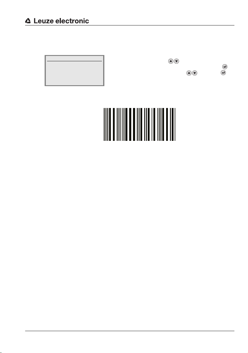
3.6 Bar code reading
Modul 0,5
6677889900
With the aid of the "Action menu", you can instruct the BCL 558i to read a bar code.
Actions
o Start decoding
o Start alignment
o Start auto-setup
o Start teach-in
To test, you can use the following bar code in the 2/5 Interleaved format. The bar code
module here is 0.5:
The read information appears in the display and is simultaneously passed on to the superior
system (PLC or PC).
Please check the incoming data of the bar code information there.
Alternatively, you can connect a photoelectric sensor or a 24 V DC switching signal to the
SW IN/OUT socket for read activation. To do this, however, you must appropriately
configure the switching input (see chapter 7.2.3 "SW IN/OUT – Switching input/switching
output").
In the main menu, use the buttons to select the
Actions menu item. Activate the Actions menu with .
Then select Start decoding with and press
again to start the bar code reading operation.
Leuze electronic BCL 558i 19
TNT 35/7-24V
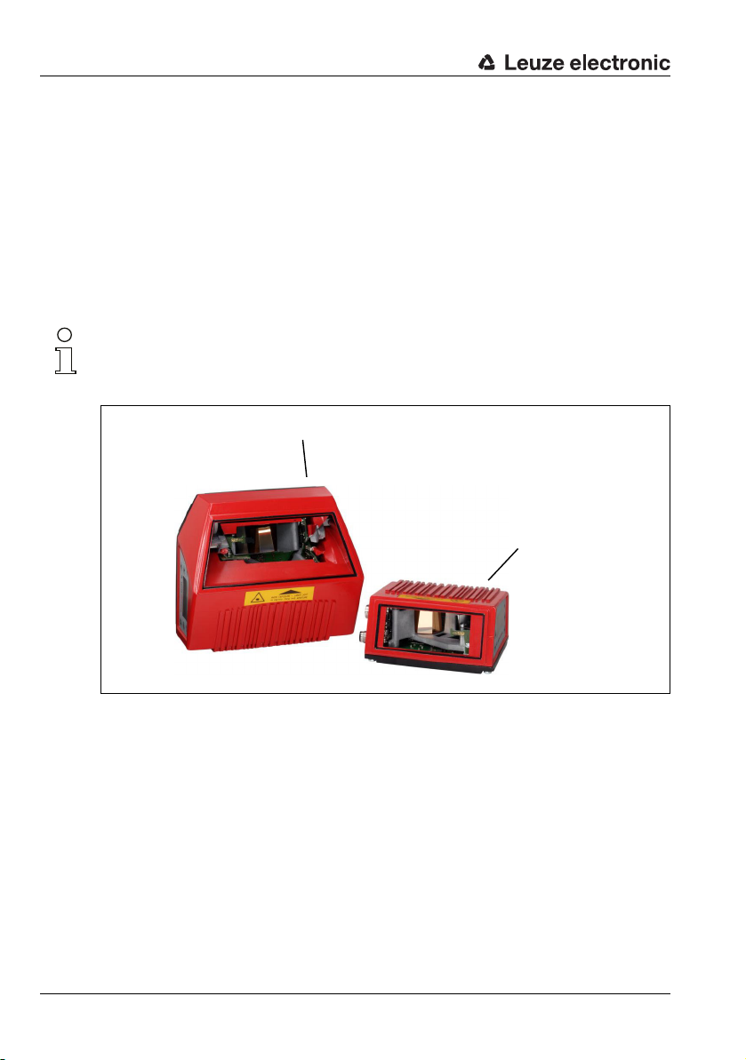
4 Device description
Line scanner
Oscillating-mirror scanner /
Line scanner with deflection mirror
4.1 About the bar code readers of the BCL 500i series
Bar code readers of the BCL 500i series are high-speed scanners with integrated decoder
for all commonly used bar codes, e.g. 2/5 Interleaved, Code 39, Code 128, EAN 8/13 etc.,
as well as codes from the GS1 DataBar family.
Bar code readers of the BCL 500i series are available in various optics models as well as
line scanners, line scanners with deflection mirrors, oscillating mirrors and also optionally
as heated models.
Notice!
Please note: the BCL 558i line scanner with deflection mirror (perpendicular beam
exit) is currently not available.
Figure 4.1: Line scanner, line scanner with deflection mirror and oscillating-mirror scanner
The extensive options for device configuration via display or software enable adaptation to
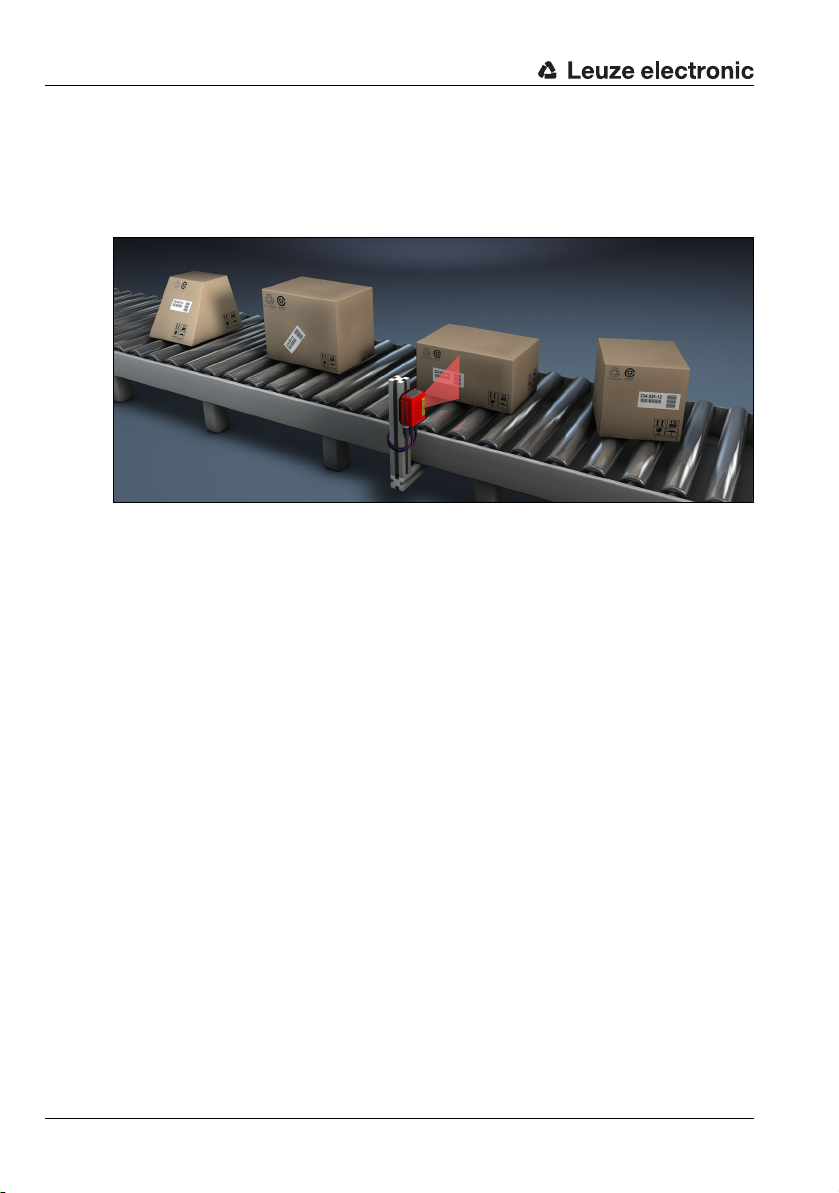
a multitude of reading tasks. Due to the large reading distance combined with the great
depth of field and a very compact construction, the device is ideally suited for package and
20 BCL 558i Leuze electronic
pallet transportation systems. In general, the bar code readers of the BCL 500i series are
designed for the conveyor and storage technology market.
The interfaces (RS 232, RS 485 and RS 422) integrated in the various device models and
the fieldbus systems (PROFIBUS DP, PROFINET-IO, Ethernet TCP/IP / UDP and
EtherNet/IP) of the BCL 500i series bar code readers offer optimum connection to the superior host system.

4.2 Characteristics of the bar code readers of the BCL 500i series
Performance features:
• Integrated fieldbus connectivity = i -> Plug-and-Play fieldbus coupling and easy
networking
• Numerous interface variants facilitate connection to the superior systems
• RS 232, RS 422 as well as with integrated multiNet plus master
• RS 485 and multiNet plus slave
alternatively, various fieldbus systems, such as
•PROFIBUS DP
•PROFINET-IO
• Ethernet TCP/IP and UDP
• EtherNet/IP
• Integrated code fragment technology (CRT) enables the identification of soiled or damaged bar codes
• Maximum depth of field and reading distances from 200 mm to 2400mm
• Large optical opening angle and, thus, large reading field width
• High scanning rate from 800 - 1200 scans/s for fast reading tasks
• Intuitive, backlit, multi-language display with user-friendly menu navigation
•Integrated USB 1.1 service interface
• Adjustment of all device parameters with a web browser
• Connection options for an external parameter memory
• Easy alignment- and diagnosis functions
• M 12 connections with Ultra-Lock™ technology
• Four freely programmable switching inputs/outputs for the activation or signaling of
states
• Automatic monitoring of the read quality with autoControl
• Automatic recognition and setting of the bar code type using autoConfig
• Reference code comparison
• Optional heating models to -35°C
• Heavy-duty housing of protection class IP 65
Notice!
Information on technical data and characteristics can be found in chapter 5.
TNT 35/7-24V
General information
The integrated fieldbus connectivity = i contained in the bar code readers of the BCL 500i
series facilitates the use of identification systems which function without connector unit or
gateways. The integrated fieldbus interface considerably simplifies handling. The Plug-andPlay concept enables easy networking and very simple commissioning: Directly connect the
respective fieldbus and all configuration is performed with no additional software.
For decoding bar codes, the bar code readers of the BCL 500i series make available the
proven CRT decoder with code fragment technology:
Leuze electronic BCL 558i 21
The proven code fragment technology (CRT) enables bar code readers of the BCL 500i
series to read bar codes with a small bar height, as well as bar codes with a damaged or
soiled print image.
With the aid of the CRT decoder, bar codes can also be read without problem in other
demanding situations, such as with a large tilt angle (azimuth angle or even twist angle).
Figure 4.2: Possible bar code orientation
The BCL 558i can be operated and configured using the integrated webConfig tool via the
USB service interface; alternatively, the bar code readers can be adjusted using configuration commands via the host/service interface.
The BCL 558i needs a suitable activation to start a read process as soon as an object is in
the reading field. This opens a time window ("reading gate") in the BCL 558i for the read
process during which the bar code reader has time to detect and decode a bar code.
In the basic setting, triggering takes place through an external reading cycle signal.
Alternative activation options include online commands via the host interface and the
autoReflAct function.
Through the read operation, the BCL 558i collects additional useful pieces of data for diagnosis which can also be transmitted to the host. The quality of the read operation can be
inspected using the alignment mode which is integrated in the webConfig tool.
A multi-language display with buttons is used to operate the BCL 558i as well as for visualization purposes. Two LEDs provide additional optical information on the current operating
state of the device.
The four freely configurable switching inputs/outputs "SWIO 1 … SWIO 4" can be assigned
various functions and control e.g. activation of the BCL 558i or external devices, such as a
PLC.
System, warning and error messages provide assistance in setup/troubleshooting during
commissioning and read operation.
22 BCL 558i Leuze electronic
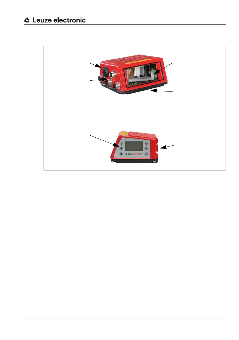
4.3 Device construction
USB interface
M12 connection
technology
Reading window
Dovetail mounting and
4 mounting threads
Dovetail mounting and
2 mounting threads
Display, LEDs
and buttons
Figure 4.3: Device construction
Leuze electronic BCL 558i 23
TNT 35/7-24V
4.4 Reading techniques
4.4.1 Line scanner (single line)
A line (scan line) scans the label. Due to the opt. opening angle, the reading field width is
dependent on the read distance. Through the movement of the object, the entire bar code
is automatically transported through the scan line.
The integrated code fragment technology permits twisting of the bar code (tilt angle) within
certain limits. These are dependent on the transport speed, the scanning rate of the scanner
and the bar code properties.
Areas of application of the line scanner
The line scanner is used:
• when the bars of the bar code are printed in the conveying direction ('ladder arrangement').
• with bar codes having very short bar lengths.
• when the ladder code is turned out of the vertical position (tilt angle).
• when the scanning distance is large.
Figure 4.4: Deflection principle for the line scanner
24 BCL 558i Leuze electronic
4.4.2 Line scanner with oscillating mirror
The oscillating mirror deflects the scan line additionally to both sides across the scan direction at a randomly adjustable oscillation frequency. In this way, the BCL 558i can also scan
larger areas or spaces for bar codes. The reading field height (and the scan line length useful
for evaluation) depends on the reading distance due to the optical beam width of the oscillating mirror.
Areas of application of the line scanner with oscillating mirror
For line scanners with oscillating mirror, oscillation frequency, start/stop position etc. are
adjustable. It is used:
• when the position of the label is not fixed, e.g. on pallets – various labels can, thus,
be detected at various positions.
• when the bars of the bar code are printed perpendicular to the conveying direction
('picket fence arrangement').
• when reading stationary objects.
• when the bar code is turned out of the horizontal position.
• when the scanning distance is large.
• when a large reading field (reading window) has to be covered.
Figure 4.5: Deflection principle for the line scanner with oscillating mirror add-on
Leuze electronic BCL 558i 25
TNT 35/7-24V
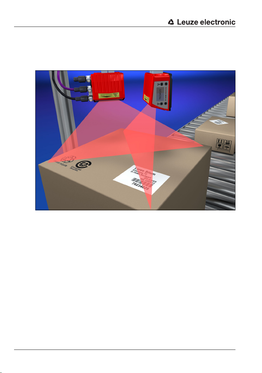
4.4.3 Omnidirectional reading
In order to read arbitrarily oriented bar codes on an object, at least 2 bar code readers are
necessary. If the bar code is not printed over-square, i.e. bar length > code length, bar code
readers with integrated code fragment technology are necessary.
Figure 4.6: Principle arrangement for omnidirectional reading
26 BCL 558i Leuze electronic
4.5 Fieldbus systems
Various product variants of the BCL 500i series are available for connecting to different
fieldbus systems such as PROFIBUS DP, PROFINET-IO, Ethernet and EtherNet/IP.
4.5.1 EtherNet/IP
The BCL 558i is designed as an EtherNet/IP device (acc. to IEEE 802.3) with a standard
baud rate of 10/100 Mbit. EtherNet/IP makes use of the Common Industrial Protocol (CIP)
as an application layer for the user. The functionality of the device is defined via parameter
sets which are clustered in objects, classes and instances. These are contained in an EDS
file which, depending on the version of the control software, can be used to configure and
integrate the BCL 558i into the system. A fixed MAC ID is assigned to each BCL 558i by the
manufacturer; this ID cannot be changed.
The BCL 558i automatically supports the transmission rates of 10 Mbit/s (10Base T) and
100 Mbit/s (100Base TX), as well as auto-negotiation and auto-crossover.
The electrical connection of the supply voltage, the interface and the switching inputs/
outputs on the BCL 558i is performed via several M12 connectors.
Additional information on the electrical connection can be found in chapter 7.
The BCL 558i supports the following protocols and services:
• EtherNet/IP
•DHCP
•HTTP
•ARP
•PING
• Telnet
• BootP
Notice!
The BCL 558i communicates via the Common Industrial Protocol (CIP).
CIP Safety, CIP Sync and CIP Motion are not supported by the BCL 558i.
Further information on commissioning can be found in chapter 10.
Leuze electronic BCL 558i 27
TNT 35/7-24V
 Loading...