

Page 1
smd
Phone: 800.894.0412 - Fax: 888.723.4773 - Web: www.clrwtr.com - Email: [email protected]
Series Drives
Modbus Communications Reference Guide
Page 2

About These Instructions
Phone: 800.894.0412 - Fax: 888.723.4773 - Web: www.clrwtr.com - Email: [email protected]
Page 3

Contents
Phone: 800.894.0412 - Fax: 888.723.4773 - Web: www.clrwtr.com - Email: [email protected]
1 Safety Information .............................................................................................................1
1.1 Warnings, Cautions and Notes ..............................................................................1
1.1.1 General ....................................................................................................1
1.1.2 Application ...............................................................................................1
1.1.3 Installation ...............................................................................................1
1.1.4 Electrical Connection ................................................................................2
1.1.5 Operation .................................................................................................2
1.2 Reference and Links .............................................................................................2
2 Introduction .......................................................................................................................3
2.1 RS485 Details .......................................................................................................3
2.2 Electrical Installation .............................................................................................3
2.2.1 Cable Type ...............................................................................................3
2.2.2 Connections and Shielding .......................................................................3
2.2.3 Network Termination ................................................................................4
2.3 Modbus Details .....................................................................................................4
2.4 Universal Registers ...............................................................................................6
3 Data Representation - Internal and External .......................................................................7
3.1 Register Format ....................................................................................................7
3.2 Data Types ...........................................................................................................7
3.3
4
smd
4.1 Control Parameter .................................................................................................8
4.2 Serial Address ......................................................................................................8
4.3 Serial Communications Parameter ........................................................................8
4.4 Watchdog Timer ...................................................................................................9
4.5 Unlocking & Locking Controls ...............................................................................10
4.6 Unlocking & Locking Programming Parameters only .............................................10
4.7 Monitoring Only Operation ....................................................................................10
4.8 Normal Control Operation Sequence .....................................................................11
4.9 Start/Stop, Speed Control and Parameter Change Operation .................................11
smd
Drive Registers ..............................................................................................7
Drive Setup & Operation ............................................................................................8
i RG-SDMOD
Page 4

Contents
Phone: 800.894.0412 - Fax: 888.723.4773 - Web: www.clrwtr.com - Email: [email protected]
5
smd
Drive Control Registers ..............................................................................................12
5.1 Abbreviations ........................................................................................................13
5.2 Drive Control - Register #1....................................................................................13
5.3 Drive Hardware Configuration - Register #22 ........................................................14
5.4 Drive Status - Registers #24-29 ............................................................................15
5.4.1 Reading Register #24 ...............................................................................15
5.4.2 Operational Status - Register #26 .............................................................16
5.4.3 Actual Rotational Direction - Registers #24 & 27 ......................................16
5.4.4 Control Mode - Registers #24 & 27 ..........................................................16
5.4.5 Speed Command Source - Registers #24 & 28 .........................................17
5.4.6 Speed Reference Status - Registers #24 & 28 ..........................................17
5.4.7 Present Fault - Registers #24 & 29 ...........................................................17
5.4.8 Commanded Rotational Direction - Registers #24 & 29 ............................18
5.5 Motor Volts - Register #30 ....................................................................................18
5.6 Serial Speed - Register #40 ..................................................................................18
5.7 Unlock Commands - Register #48 .........................................................................18
5.8 Unlock Parameters - Register #49 ........................................................................18
5.9 Register Version ....................................................................................................18
6
smd
Programming Parameters ..........................................................................................19
6.1 Format ..................................................................................................................19
6.2 Parameter List ......................................................................................................20
7 Quick Start Instructions .....................................................................................................25
7.1 Initial Settings .......................................................................................................25
7.2 Drive Control .........................................................................................................26
7.3 Basic Drive Commands .........................................................................................26
7.4 Basic Drive Status .................................................................................................27
RG-SDMOD ii
Page 5

1 Safety Information
Phone: 800.894.0412 - Fax: 888.723.4773 - Web: www.clrwtr.com - Email: [email protected]
1.1 Warnings, Cautions and Notes
1.1.1 General
Some parts of Lenze controllers (frequency inverters, servo inverters, DC controllers) can be live, moving
and rotating. Some surfaces can be hot.
Non-authorized removal of the required cover, inappropriate use, and incorrect installation or operation
creates the risk of severe injury to personnel or damage to equipment.
All operations concerning transport, installation, and commissioning as well as maintenance must be
carried out by qualified, skilled personnel (IEC 364 and CENELEC HD 384 or DIN VDE 0100 and IEC report
664 or DIN VDE0110 and national regulations for the prevention of accidents must be observed).
According to this basic safety information, qualified skilled personnel are persons who are familiar with
the installation, assembly, commissioning, and operation of the product and who have the qualifications
necessary for their occupation.
1.1.2 Application
Safety Information
Drive controllers are components designed for installation in electrical systems or machinery. They are
not to be used as appliances. They are intended exclusively for professional and commercial purposes
according to EN 61000-3-2. The documentation includes information on compliance with EN 61000-3-2.
When installing the drive controllers in machines, commissioning (i.e. the starting of operation as directed)
is prohibited until it is proven that the machine complies with the regulations of the EC Directive 98/37/EC
(Machinery Directive); EN 60204 must be observed.
Commissioning (i.e. starting drive as directed) is only allowed when there is compliance to the EMC Directive
(89/336/EEC).
The drive controllers meet the requirements of the Low Voltage Directive 73/23/EEC. The harmonised
standards of the series EN 50178/DIN VDE 0160 apply to the controllers.
The availability of controllers is restricted according to EN 61800-3. These products can cause
radio interference in residential areas. In the case of radio interference, special measures may be
necessary for drive controllers.
1.1.3 Installation
Ensure proper handling and avoid excessive mechanical stress. Do not bend any components and do not
change any insulation distances during transport or handling. Do not touch any electronic components
and contacts. Controllers contain electrostatically sensitive components, which can easily be damaged by
inappropriate handling. Do not damage or destroy any electrical components since this might endanger
your health! When installing the drive ensure optimal airflow by observing all clearance distances in the
drive's user manual. Do not expose the drive to excessive: vibration, temperature, humidity, sunlight, dust,
pollutants, corrosive chemicals or other hazardous environments.
1 RG-SDMOD
Page 6
1.1.4 Electrical Connection
Phone: 800.894.0412 - Fax: 888.723.4773 - Web: www.clrwtr.com - Email: [email protected]
When working on live drive controllers, applicable national regulations for the prevention of accidents (e.g.
VBG 4) must be observed.
The electrical installation must be carried out in accordance with the appropriate regulations (e.g.
cable cross-sections, fuses, PE connection). Additional information can be obtained from the regulatory
documentation.
The regulatory documentation contains information about installation in compliance with EMC (shielding,
grounding, filters and cables). These notes must also be observed for CE-marked controllers.
The manufacturer of the system or machine is responsible for compliance with the required limit values
demanded by EMC legislation.
1.1.5 Operation
Systems including controllers must be equipped with additional monitoring and protection devices according
to the corresponding standards (e.g. technical equipment, regulations for prevention of accidents, etc.).
You are allowed to adapt the controller to your application as described in the documentation.
Safety Information
DANGER!
• After the controller has been disconnected from the supply voltage, do not touch the live components and power
connection until the capacitors have discharged. Please observe the corresponding notes on the controller.
• Do not continuously cycle input power to the controller more than once every three minutes.
• Close all protective covers and doors during operation.
WARNING!
Network control permits automatic starting and stopping of the inverter drive. The system design must incorporate adequate
protection to prevent personnel from accessing moving equipment while power is applied to the drive system.
Table 1: Pictographs used in these instructions
Pictograph Signal word Meaning Consequences if ignored
DANGER!
WARNING!
STOP!
NOTE
Warning of Hazardous Electrical
Voltage.
Impending or possible danger
for persons
Possible damage to equipment Damage to drive system or its surroundings
Useful tip: If observed, it will
make using the drive easier
Reference to an imminent danger that may
result in death or serious personal injury if the
corresponding measures are not taken.
Death or injury
1.2
RG-SDMOD 2
Page 7
2 Introduction
Phone: 800.894.0412 - Fax: 888.723.4773 - Web: www.clrwtr.com - Email: [email protected]
This document defines the specifics required for Modbus serial communication with a Lenze-AC Tech
standard
with normal drive capabilities and operations is assumed. If this is not the case, refer to the
Operating Instructions (SL03) for more information.
2.1 RS485 Details
smd
Series drive for control, status monitoring, and programming parameters. A familiarity
Introduction
smd
Series
Only standard
smd
models with an “L” as the eighth digit in the model number (ex. ESMD371L4TXA) are
equipped with Modbus RS-485 capabilities. When using this feature the drive can communicate with a
personal computer (PC), programmable logic controller (PLC), or other external device that utilizes Modbus
RS-485 serial communication for control or monitoring. Refer to the
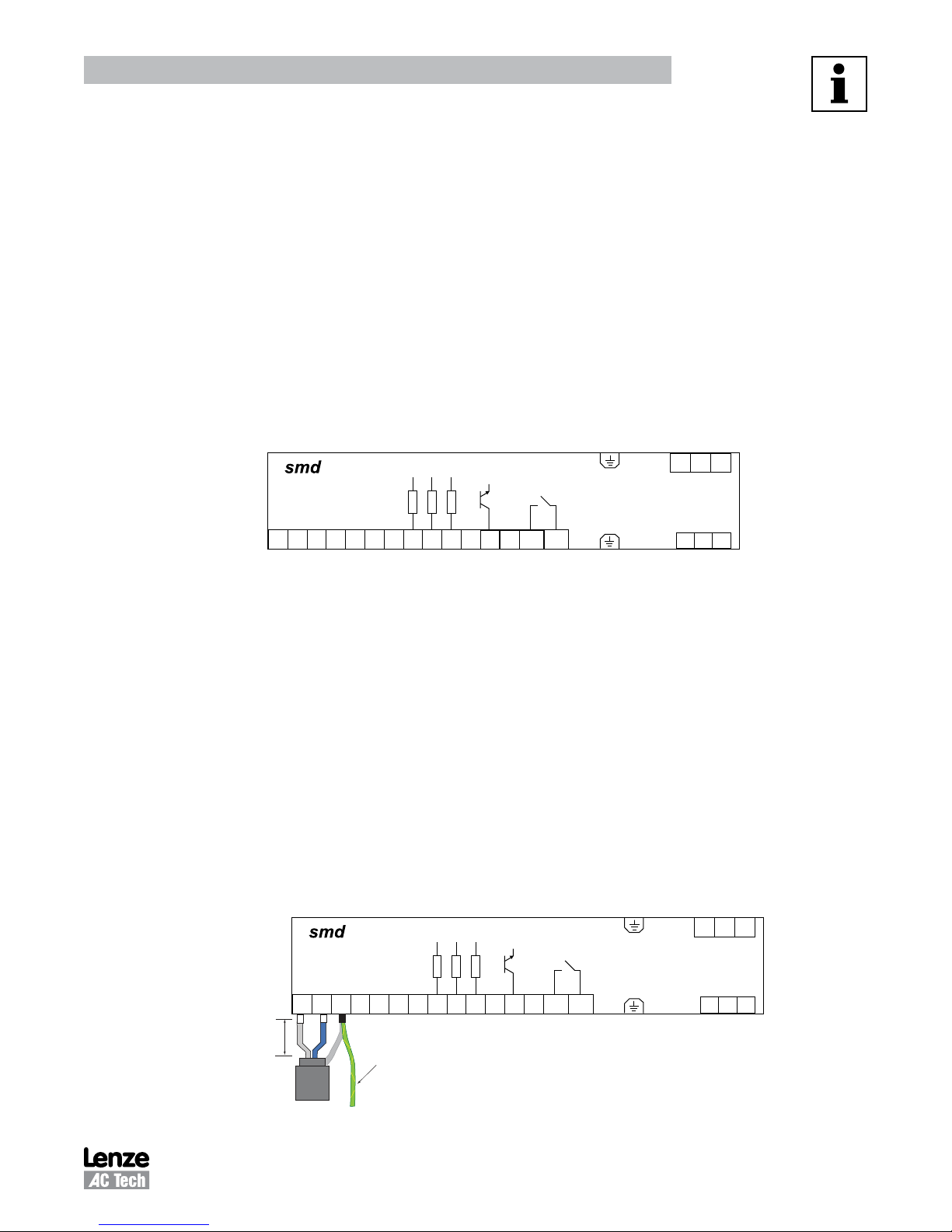
connection details. Figure 1 illustrates the
used for RS485 communication.
COM
TXA
TXB
771 72
2.2 Electrical Installation
2.2.1 Cable Type
For RS485 Modbus networks, use a quality shielded twisted pair cable. The use of low quality cable will
result in excess signal attenuation and data loss.
2.2.2 Connections and Shielding
To ensure good system noise immunity all networks cables should be correctly grounded:
+10 V
+12 V
AIN
8 9 20 28 E1
smd
control strip. Terminals 7 (COM), 71 (TXB) and 72 (TXA) are
E2
E3
Figure 1:
COM
20 A1
smd
K14
K12
62
Control Strip
smd
Operating Instructions (SL03) for
L1 L2
L3
U V W
• Minimum grounding recommendation: ground the network cable shield once in every cubical.
• Ideal grounding recommendation: ground the network cable on or as near to each drive as possible.
• For wiring of cable to the
smd
control terminal, the unscreened cable cores should be kept as short as
possible; recommended maximum of 20mm. Ground the shield at the drive end only.
• In addition, grounding terminal 7 on the
+10 V
COM
AIN
TXA
TXB
8 9 20 28 E1
771 72
20mm
max
Connect to
drive earth
(PE)
+12 V
smd
is recommended when using serial communications.
COM
K14
E2
E3
20 A1
62
K12
Figure 2: Connector Wiring Diagram
3 RG-SDMOD
L1 L2
U V W
L3
Page 8
Introduction
Phone: 800.894.0412 - Fax: 888.723.4773 - Web: www.clrwtr.com - Email: [email protected]
2.2.3 Network Termination
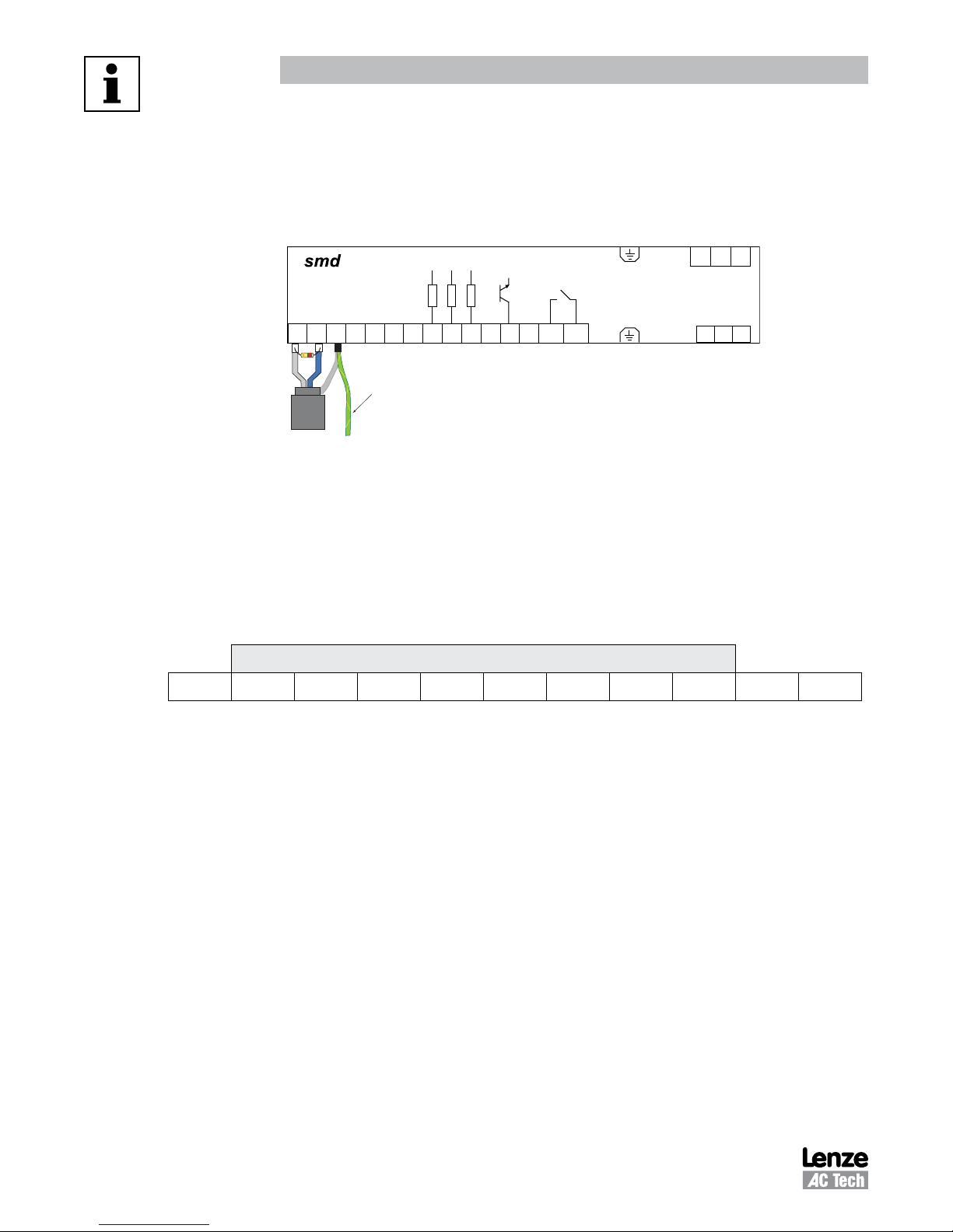
For an RS-485 network it is essential to install the specified termination resistors (120W), i.e. one at both
ends of a network segment. Failure to do so will result in signals being reflected back along the cable which
will cause data corruption. An external 120W 1/4W resistor can be connected as shown in Figure 3.
120Ω
1/4W
2.3 Modbus Details
A.
smd
Drives running the Modbus communication protocol use the RTU (Remote Terminal Unit)
transmission mode and are slaves only. Therefore, the device communicating with the drives must
be a Modbus Master. The baud rate is 9600. The default setting is no parity (two stop bits). There are
provisions for: No parity, 1 stop bit (PV507); Odd parity, 1 stop bit; and Even parity 1 stop bit as well.
The bit sequence is:
TXB
COM
AIN
TXA
8 9 20 28 E1
771 72
Connect to
drive earth
COM
+10 V
+12 V
K14
62
K12
(PE)
E2
E3
20 A1
Figure 3: Network Termination Resistor
L1 L2
U V W
L3
DATA
Start bit 1 2 3 4 5 6 7 8 Stop bit Stop bit
B. At this time the
smd
drive does not support the broadcast function of the protocol.
C. IMPORTANT NOTE: Modbus 3X and 4X Registers are numbered starting at 1. However, when transmitted
to a slave over the serial link, the actual address transmitted is one less. This is because the addresses
are numbered starting from 0. The
smd
register numbers always correspond exactly with the address transmitted. As a result, MODBUS
REGISTER NUMBERS ARE ALWAYS ONE GREATER THAN
WORDS “REGISTER #xx” APPEAR, IT SHOULD BE ASSUMED THAT THEY MEAN “
smd
register numbers are also numbered starting from 0. Therefore,
smd
REGISTER NUMBERS. WHENEVER THE
smd
REGISTER xx” and
the Modbus Register number will be one larger. In some instances we may show both for clarity. For
example: “Register #24 (Modbus Register #25) . . .”
RG-SDMOD 4
Page 9

Introduction
Phone: 800.894.0412 - Fax: 888.723.4773 - Web: www.clrwtr.com - Email: [email protected]
D. The function codes supported by the
03 Read Holding Register (4X references). In general we can read only one register at a time. However,
there are a few limited exceptions.
Exception One:
Register #24 (Modbus Register #25) Drive Status, can also be read as a group of 6 words.
Exception Two:
Parameter C99 (Software Version) is a 4-word read.
04 Read Input Register (3X references). As with function 03, we read one register at a time except
where noted.
06 Preset Single Register (4X references). Write single register.
16 Preset Multiple Registers (4X references). Although the function is for multiple registers, we will
accept only a single register to be written.
Note: Since we do not differentiate between 4X and 3X references, function codes 03 and 04 are
treated identically.
E. Exception codes:
01 - Command rejected, Illegal function
02 - No such register
03 - Data out of range
04 - Wrong data format
06 - Slave device busy
smd
drives are:
F. The
G.
5 RG-SDMOD
smd
drive will most nearly conform to the Modicon® Micro 84 in capabilities. This may be of
importance when configuring networks for DDE Servers.
Page 10
Introduction
Phone: 800.894.0412 - Fax: 888.723.4773 - Web: www.clrwtr.com - Email: [email protected]
2.4 Universal Registers
Lenze-AC Tech manufactures several drive families. Currently the QC, MC, MCH, SC, TC,
smd, Tmd
and
SMV Series drives support Modbus based communications. Since each drive family has different parameters
and size ranges, the parameter (register) definitions are in many cases quite different. In order to facilitate
communication in a network with a mix of drive types, certain Lenze-AC Tech Register locations have been
made universal among Lenze-AC Tech drives. While their locations are consistent, their contents may vary
as defined in Table 2.
Table 2: Contents of Universal Registers
smd
Reg # Function
1 Drive Control (WRITE ONLY). Not all drives will have all control functions but when the function is
available it will be at a defined bit location within Register #1. Drive Family and register Configuration
Number dependent.
19 Drive Family (READ ONLY) This register is consistent among all Lenze-AC Tech drives:
- 64 -- QC family - 67 -- - 70 -- TC family
Tmd
- 65 -- MC family - 68 -- MCH family - 71 --
smd
- 66 -- SC family - 69 --
21 Drive Size (READ ONLY). Code to identify Power (HP/KW) and Line Voltage of the drive. Family
dependent. For the
24 Drive Status (READ ONLY). Various operational variables.
48 Unlock Control (WRITE ONLY).
49 Unlock Writing of registers (WRITE ONLY).
50 Parameter Configuration Number (READ ONLY).
smd
series it always reads zero.
family - 72 -- SMV family
family
RG-SDMOD 6
Page 11
Data & Register Format
Phone: 800.894.0412 - Fax: 888.723.4773 - Web: www.clrwtr.com - Email: [email protected]
3 Data Representation - Internal and External
3.1 Register Format
All registers are 16 bits. The data within these registers can take on the following forms:
• Individual bit commands (16 per register).
Example: Register #1 (Modbus Register #2).
• Individual bit flags (16 per register).
Example: Register #22.
• A chain of two 8 bit unsigned integers.
• A 16 bit unsigned integer.
This unsigned integer could in turn represent many different types of data with various scaling
rules and units, which are defined by the DATA TYPE of the register.
3.2 Data Types
3.3
Data passed in registers across the Modbus communications link are always in INTERNAL units. The drive
itself may show the information in alternate DISPLAYED units. For Example: drive speeds are always stored
internally as tenths of a Hz but the drive may display that speed in whole Hz by dropping the tenth using
programmed conversion factors. Table 3 lists examples of the internal units used on the
Table 3:
Type Unit Example
SPEED .1Hz 100Hz = 1000
TIME .1Sec 30.0 Sec = 300
smd
Drive Registers
Registers #0 through #50: (Modbus Registers #1 to #51) Reserved for configuration and control
Registers #51 through #255 (Modbus Registers #52 to #256) Reserved for the drives’ programming
mode parameters. Programming Mode Parameters are the parameters
that can be accessed from the local keypad on the drive.
The entries in Table 6 are based on
SW 2.00 and 2.01 (Parameter Configuration 507). If a later revision of software were to change register
definitions, drive operation could be seriously affected. This will be identified for a given drive by examining
Register #50 (Parameter Configuration Number). The number displayed at power up on drive display can
also identify it. If it is not 400 or 507, writing to any register on the drive MUST NOT BE ATTEMPTED unless
your Controller has been setup to support the new configuration.
smd
smd
Series Internal Units
Drive Software # 1.51 (Parameter Configuration = 400) and Drive
smd
series.
7 RG-SDMOD
Page 12
Drive Setup & Operation
Phone: 800.894.0412 - Fax: 888.723.4773 - Web: www.clrwtr.com - Email: [email protected]
4
smd
Drive Setup & Operation
4.1 Control Parameter
In order to communicate using Modbus protocol, the
be set to one of the selections listed in Table 4.
Setting Source Description
Program
(Monitoring)
8 Modbus Terminal Analog Input Drive is controlled via terminal programming and is monitored via Modbus
9 Modbus Terminal c40 Drive is controlled via terminal programming and is monitored via Modbus
10 Modbus Modbus Analog Input Drive is controlled via serial interface and is monitored via Modbus
11 Modbus Modbus c40 Drive is controlled via serial interface and is monitored via Modbus
Control
(Start/Stop,
Direction)
4.2 Serial Address
smd
Control Source Setpoint (parameter #C01) must
Table 4: Control Source Setpoint C01 (Register 51)
Speed
(Source)
interface or keypad. The default speed source is the analog input.
interface or keypad. The default speed source is c40.
interface or keypad. The default speed source is the analog input.
interface or keypad. The default speed source is c40
The
smd
drive has a serial address parameter that must be programmed prior to attempting to operate the
serial interface. Set Parameter C09 (Network Address) to a valid address (1-247).
Tip
Most Modbus devices ship with a default address of 1. As such, it is recommended to not
use address 1 in order to avoid duplicate address conflicts when replacing devices.
4.3 Serial Communications Parameter
Lenze-AC Tech drives have a Serial Communications Parameter that governs the operation of the serial
link. On
Control Source Setpoint must first be set to a value of 8-11. Table 5a lists the selections for
c25, Serial Baud Rate. Table 5b lists the selections for the controller's reaction to serial timeout (n22).
smd
drives this is c25, Serial Baud Rate {Register #95 (PC400) or #103 (PC507)}. Parameter C01
Tables 5a & 5b: Serial Communications
Table 5a: Serial Baud Rate c25 Table 5b: Serial Timeout Action n22
Setting Description Setting Description
0 9600, 8, N, 2 0 Not active
1 9600, 8, N, 1 1 Inhibit
2 9600, 8, E, 1 2 Quick Stop
3 9600, 8, O, 1 3 Trip Fault FC3
smd
Parameter
The Serial Communications Parameter (c25) must be appropriately programmed prior to attempting to
communicate with the drive. The timeout period is programmed in Parameter n23, Serial Fault Time.
RG-SDMOD 8
Page 13
4.4 Watchdog Timer
Phone: 800.894.0412 - Fax: 888.723.4773 - Web: www.clrwtr.com - Email: [email protected]
The
smd
drive is equipped with a Serial Link “Watchdog Timer”. If the Modbus Master wishes to control
the drive (start, stop, forward, reverse, etc.) it must first “Unlock Controls” (section 4.4). If the Watchdog
Timer is enabled and controls have been unlocked, the Master MUST PERIODICALLY COMMUNICATE with
the drive or the timer will timeout. Communications should typically be done at less than 1/2 the interval
specified in n23, Serial Fault Time.
The Watchdog Timer does not operate unless Controls have been UNLOCKED via Register #48, or parameters
writing has been unlocked via Register #49. In case of unlocking parameters only, watchdog timer will
disable write permission but will not stop the drive.
The Watchdog Timer is setup using parameters n22 (Serial Timeout Action) and n23 (Serial Fault Time).
Drive Setup & Operation
Selection of n22 determines the
n22 = 0: Not Active The Watchdog Timer is disabled
n22 = 1: Controller Inhibit If the drive doesn't receive valid communication for period longer
n22 = 2: Quick Stop If drive doesn't receive valid communication for period longer than
n22 = 3: Trip Fault FC3 If drive doesn't receive valid communication for period longer than
The setting of Parameter n23, Serial Fault Time, sets the serial timeout length in miiliseconds. The valid
range is 50 - 65535 ms and the default setting is 50ms.
NOTE - Trip Prevention
To prevent erroneous timeout trips, make sure the time set in parameter n23 is appropriate
for the particular network. The defualt value of 50ms may be too restrictive.
WARNING
smd
drive's reaction to serial timeout:
than time specified in parameter n23, it will COAST to a STOP and
status display (c61) will show inhibit state 'Inh'.
time specified in parameter n23, it will RAMP to a STOP and status
display (c61) will show inhibit state 'Stp'.
time specified in parameter n23, it will TRIP with an 'FC3' fault.
Disabling the Watchdog Timer may cause injury to personnel and/or damage to equipment.
The Watchdog Timer should only be disabled during configuration or diagnosis to prevent
nuisance timeout trips.
9 RG-SDMOD
Page 14

Drive Setup & Operation
Phone: 800.894.0412 - Fax: 888.723.4773 - Web: www.clrwtr.com - Email: [email protected]
4.5 Unlocking & Locking Controls
Registers #48 and #1 are used in Unlocking and Locking Controls.
• A write to Register #48 (Unlock Controls) with a value of 0 will unlock controls. This enables the writing
of Register #1 – the Drive Control Register and register #40 (keypad speed command).
Note: C01 must be set to either 10 or 11 in order to unlock serial control.
• If Register #48 (Unlock Controls) is written with a value that is the Drive’s Programming Password,
C94, then in addition to Register #1(Drive Control), writing to all other writeable registers is enabled
(e.g.: parameter C37 -- Preset Speed #1). The factory default password for
• Once Register #48 (Unlock Controls) has been written, Controls are unlocked until Register#1 bit 1
(Lock Bit) has been written, Parameter C01 is changed to a value different than 10 or 11, the drive is
powered down or a serial timeout occurs.
• Writing to Register #1 (Drive Control) with bit 1 set will Lock both Controls and Parameters (prevents
writing to any register).
• When LOCK is asserted, the drive drops out of SERIAL control. After receiving the WRITE message
when serial control is locked, the drive will return exception code 01.
smd
series drives is 0.
• Even though drive might be locked, and thus parameters and control cannot be written, parameters
and status can always be read. Refer to section 4.7,
Monitoring Only Operation
4.6 Unlocking & Locking Programming Parameters only
Registers #49 and #1 are used in Unlocking and Locking Programming Parameters.
• Writing to any writeable register other than #1 can be enabled by writing the Drive’s Programming
Password (C94) to Register #49 (Unlock Parameters). This would be done when Drive Control (start,
stop, etc.) is not required.
• The Factory Default password is 0.
• Once Register #49 (Unlock Parameters) has been written, the writing of parameter registers is unlocked
until Register #1bit 1 (Lock Bit) has been set or the drive experiences a serial timeout.
4.7 Monitoring Only Operation
1. Power up drive.
2. Set parameter C01 (Control Source Setpoint) to selection 8 or 9.
3. Simply read
4. No unlocking or watchdog issues apply for monitoring.
smd
Register #24 (Modbus Register #25) or any other readable register.
.
RG-SDMOD 10
Page 15

Drive Setup & Operation
Phone: 800.894.0412 - Fax: 888.723.4773 - Web: www.clrwtr.com - Email: [email protected]
4.8 Normal Control Operation Sequence
1. Power up drive.
2. Set parameter C01 (Control Source Setpoint) to selection 10 or 11.
3. Close terminal 28.
4. Unlock control by writing a zero to Register #48.
5. Control drive operation via various commands to Register #1 (Start, Stop, Reverse direction, etc.).
6. Set the network speed reference by setting bit 8 of Register #1. The drive must be in "SERIAL SPEED
REFERENCE" (Register #1, Drive Control) in order to control speed via Register #40.
7. Control Drive Speed by writing the Speed Commands to Register #40 (Serial Speed Command).
8. If serial timeout is activated (n22 = 1, 2 or 3), keep it from timing out by assuring that repeated reads
of drive status (Register #24, 6 registers) are performed at reasonable intervals smaller than the time
set in parameter n23.
9. Lock Control when drive operations are complete by writing a 2 to Register #1. (assert bit 1 of Register
#1).
4.9 Start/Stop, Speed Control and Parameter Change Operation
The typical sequence for a Start/Stop, Speed Control or Parameter Change operation is listed herein.
1. Power up drive.
2. Set parameter C01 (Control Source Setpoint) to selection 10 or 11.
3. Close terminal 28.
4. Unlock Controls and Parameters by writing the current programming password (default 0) to Register
#48.
5. Control Drive Operation via various commands to Register #1 (Start, Stop, Reverse direction, etc.).
6. Set the network speed reference by setting bit 8 of Register #1. The drive must be in "SERIAL SPEED
REFERENCE" (Register #1, Drive Control) in order to control speed via Register #40.
7. Control Drive Speed by writing the Speed Commands to Register #40 (Serial Speed Command).
8. Change the programming parameters (e.g., change the acceleration rate by writing new acceleration
rate to register #61)
9. If serial timeout is activated (n22 = 1, 2 or 3), keep it from timing out by assuring that repeated reads
of drive status (Register #24, 6 registers) are performed at reasonable intervals smaller than the time
set in parameter n23.
10. Lock Controls and Parameters when drive operations are complete by writing a 2 to Register #1 (assert
bit 1 of Register 1).
11 RG-SDMOD
Page 16
Drive Control & Communication
Phone: 800.894.0412 - Fax: 888.723.4773 - Web: www.clrwtr.com - Email: [email protected]
5
smd
Drive Control Registers
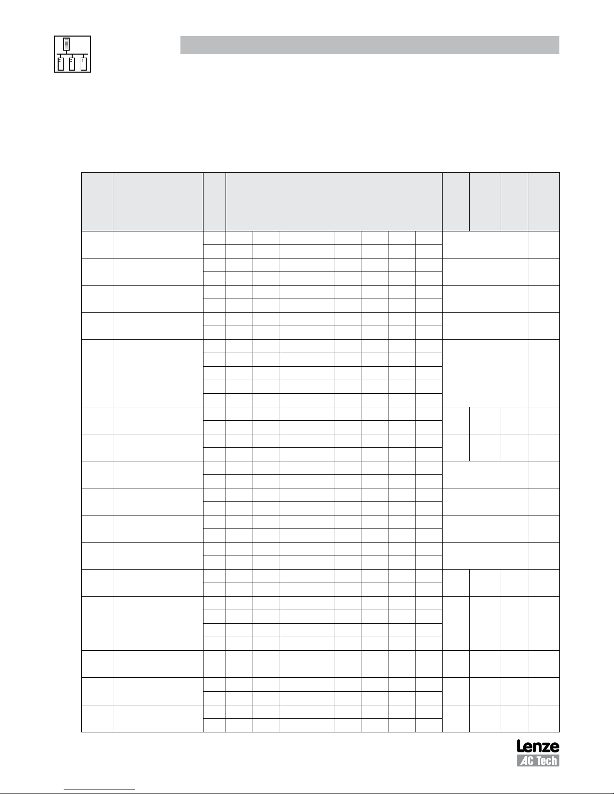
Table 6 describes the
smd
Drive Control Registers in ascending order of
representation is given in parenthesis next to the
REGISTER NAME
# (HEX
smd
representation)
1 (01) Drive Control
19 (13) Drive Family
21 (15) Drive Size
22 (16) Drive H/W
Drive Status
24 (18)
24 (18) Command Speed
25 (19) Actual Speed
26 (1A)
27 (1B)
28 (1C)
29 (1D)
30 (1E) Motor Voltage
40 (28) Serial Speed Command
48 (30) Unlock Commands
49 (31) Unlock Parameters
50 (32) Register Version
(6 register read)
(reg. #24 to 29)
Load (DH) /
Status (DL)
Act. Direction (DH)/
Control Mode (DL)
Speed Source (DH)/
Speed Reference (DL)
Fault (DH)/
Commanded Direction (DL)
Table 6:
R/W/RS
W SA 06 00 01 DH DL CRCH CRCL
RS SA 06 00 01 DH DL CRCH CRCL
R SA 03 00 13 00 01 CRCH CRCL
RS SA 03 02 00 45 CRCH CRCL
R SA 03 00 15 00 01 CRCH CRCL
RS SA 03 02 00 00 CRCH CRCL
R SA 03 00 16 00 01 CRCH CRCL
RS SA 03 02 DH DL CRCH CRCL
R SA 03 00 18 00 06 CRCH CRCL
RS SA 03 0C D1H D1L D2H D2L
R SA 03 00 18 00 01 CRCH CRCL
RS SA 03 02 DH DL CRCH CRCL
R SA 03 00 19 00 01 CRCH CRCL
RS SA 03 02 DH DL CRCH CRCL
R SA 03 00 1A 00 01 CRCH CRCL
RS SA 03 02 DH DL CRCH CRCL
R SA 03 00 1B 00 01 CRCH CRCL
RS SA 03 02 DH DL CRCH CRCL
R SA 03 00 1C 00 01 CRCH CRCL
RS SA 03 02 DH DL CRCH CRCL
R SA 03 00 1D 00 01 CRCH CRCL
RS SA 03 02 DH DL CRCH CRCL
R SA 03 00 1E 00 01 CRCH CRCL
RS SA 03 02 DH DL CRCH CRCL
R SA 03 00 28 00 01 CRCH CRCL
RS SA 03 02 DH DL CRCH CRCL
W SA 06 00 28 DH DL CRCH CRCL
RS SA 06 00 28 DH DL CRCH CRCL
W SA 06 00 30 DH DL CRCH CRCL
RS SA 06 00 30 DH DL CRCH CRCL
W SA 06 00 31 DH DL CRCH CRCL
RS SA 06 00 31 DH DL CRCH CRCL
R SA 03 00 32 00 01 CRCH CRCL
RS SA 03 02 DH DL CRCH CRCL
smd
smd
Register #. The HEX
smd
Register # in the left-most column.
Drive Control Registers
MESSAGE MIN MAX UNITS
Refer to Section 5.2 [1]
Refer to Section 5.2 [2]
Refer to Section 5.2 [3]
Refer to Section 5.3
D3H D3L D4H D4L
D5H D5L D6H D6L
CRCH CRCL
Refer to Section 5.4
0 2400 0.1 Hz [4a]
0 2400 0.1 Hz [4b]
Refer to Section 5.4.2 [4c]
Refer to Section 5.4.3/4
Refer to Section 5.4.5/6
Refer to Section 5.4.7/8 [4d]
0 250 1% 5.5
C10
C11
Min
Freq.
Max
Freq.
0 999 None 5.7
0 999 None 5.8
0 65535 None 5.9
[NOTE]
or
Section
0.1 Hz 5.6
RG-SDMOD 12
Page 17
5.1 Abbreviations
Phone: 800.894.0412 - Fax: 888.723.4773 - Web: www.clrwtr.com - Email: [email protected]
Drive Control & Communication
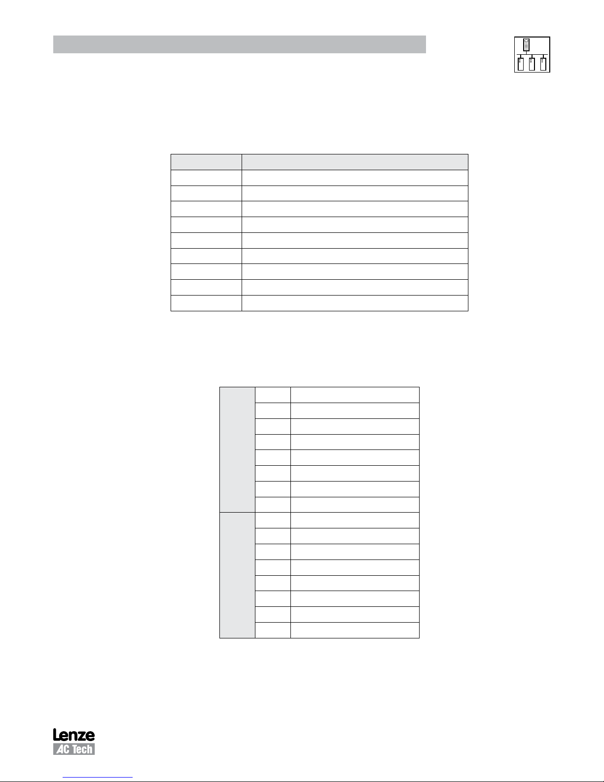
Table 7 lists the abbreviations used in Table 6
Abbreviation Description
R Read
W Write
RS Response
SA Slave Address (typically 01 through F7 hex)
CRCH Cyclic Redundancy Check High byte
CRCL Cyclic Redundancy Check Low byte
DH Data High byte
DL Data Low byte
smd
#
5.2 Drive Control - Register #1
Table 8 illustrates the Data High Byte and Data Low Byte format of Register #1, Drive Control.
smd
Drive Control Registers:
Table 7: Abbreviations
smd
Register # (Modbus Register numbers are 1 larger)
Table 8: Drive Control - Register #1
0 UPDATE BUFFERS
1 LOCK SECURITY
2 STOP DRIVE (COAST TO STOP)
3 START DRIVE
4 UNUSED
Data Low Byte
Data High Byte
5 UNUSED
6 SET REVERSE
7 SET FORWARD
8 SERIAL SPEED REFERENCE
9 LOCAL SPEED REFERENCE
10
11
12
13
14
15
The appropriate bit is set to 1. For example, to stop the drive bit two is set (send 0004H). To start the drive
send 0008H. Setting update buffers bit, enables to start the drive using downloaded data. Locking security
disables the serial drive control, the communications watchdog timer and prevents any further writing to
control or parameter registers.
13 RG-SDMOD
Page 18
Drive Control & Communication
Phone: 800.894.0412 - Fax: 888.723.4773 - Web: www.clrwtr.com - Email: [email protected]
NOTE 1 - Drive Control
• During each write to Register #1 only one bit should be set in the drive control word.
• If more than 1 bit is set, the drive responds to stop bit only.
• If stop bit is not set, but more than 1 bit is set, drive responds with exception 04.
NOTE 2 - Drive Family
• The QC and DL Series drives return 64 (40H)
• The MC Series drives return 65 (41H)
• The SC Series drives return 66 (42H)
• The MCH Series drives return 68 (44H)
• The
smd
Series drives return 69 (45H)
• The TC Series drives return 70 (46H)
• The
tmd
Series drives return 71 (47H)
• The SMV Series drives return 72 (48H)
NOTE 3 - Drive Size
On
smd
series drives this register always read zero
5.3 Drive Hardware Configuration - Register #22
Table 9 lists the
smd
Drive Hardware Configuration, Register #22. Bits 4 - 15 are not used at this time.
Table 9: Register 22 - Drive Hardware Configuration
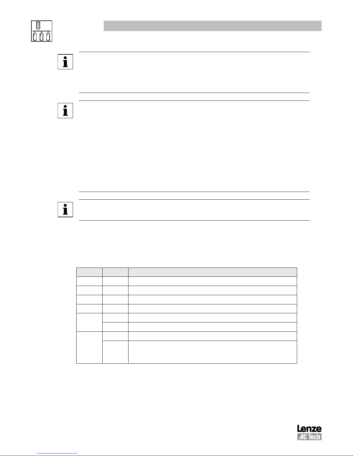
BIT # STATE MEANING
0 1 Reserved
0 Reserved
1 1 Reserved
0 Reserved
2 1 OEM defaults present
0 No OEM defaults
3 1 User data on EPM is compatible only
0 Either the parameter version of the EPM matches the current software or the
EPM is not compatible. If incompatible then one of the following faults are
responsible: CF (control fault), cF (incompatibility fault) or GF (data fault)
Bit 3 = 1: the USER data on the EPM is compatible only. The data on the EPM is valid and usable by
the drive but the parameter version of the data does not match the parameter version that the drive is
currently using. Therefore the user will not be able to edit any of the data on the EPM until they perform a
TRANSLATE with P48.
RG-SDMOD 14
Page 19
Drive Control & Communication
Phone: 800.894.0412 - Fax: 888.723.4773 - Web: www.clrwtr.com - Email: [email protected]
5.4 Drive Status - Registers #24-29
5.4.1 Reading Register #24
When reading register #24, the group of words requested can be either 1 or 6. This is an exception to the
rule of being able to read only one register at a time. If 6 words are requested at register #24, the following
will be returned:
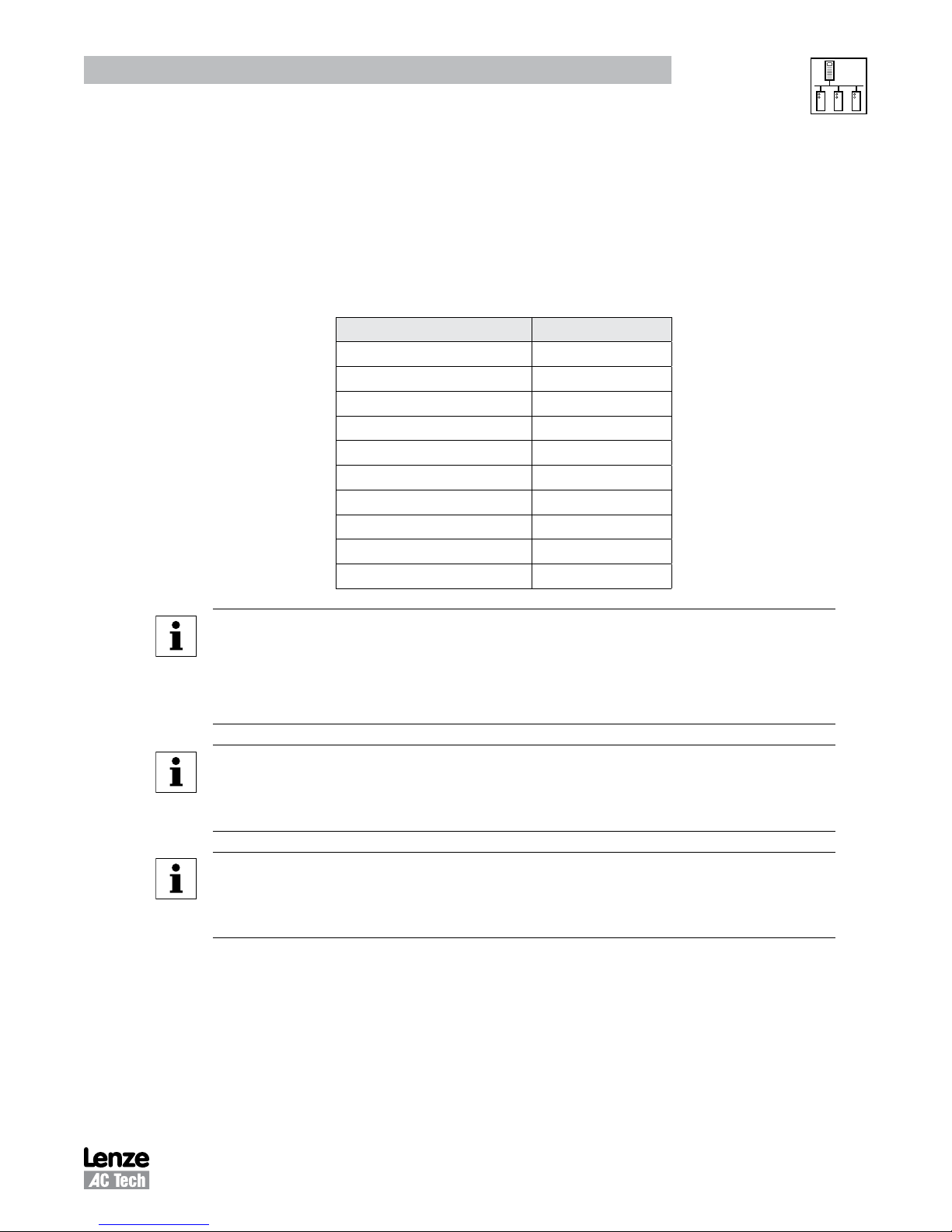
Table 10: 6 Register read at #24
Parameter Data Byte
Command Speed D1H D1L
Actual Speed D2H D2L
Load D3H
Operation Status D3L
Rotational Direction D4H
Control Mode D4L
Speed Command Source D5H
Speed Reference Status D5L
Present Fault D6H
Command Rotation D6L
NOTE 4a - Command Speed (Register #24 Bytes D1H and D1L or Register #24)
• In tenths of a Hz
• Most significant byte is first, followed by Least significant
• Example: 02 01 in hex converts to 51.3Hz in decimal (assumed 1 decimal place).
NOTE 4b - Actual Speed (Register #24 Bytes D2H and D2L or Register #25)
• In tenths of a Hz
• Most significant byte is first, followed by Least significant
NOTE 4c - Load (Register #24 Byte D3H or Register #26 DH)
• In percent of full load
• Example: 64 (one byte in hex) ==> 100 in decimal ==> 100% (drive load).
15 RG-SDMOD
Page 20
Drive Control & Communication
Phone: 800.894.0412 - Fax: 888.723.4773 - Web: www.clrwtr.com - Email: [email protected]
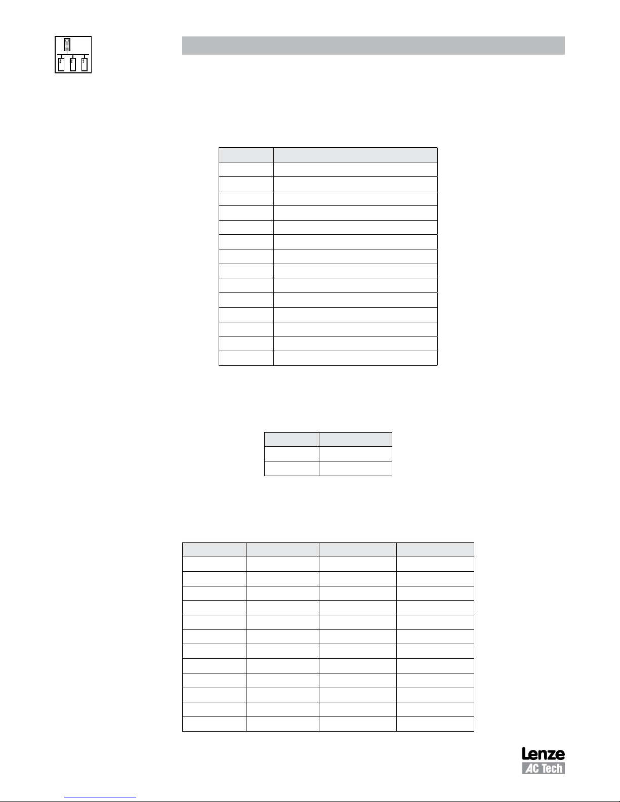
5.4.2 Operational Status - Register #26
Table 11 lists the Operational Status (Register #24 byte D3L or Register #26 DL)
Bit Parameter
0 FAULT LOCKOUT
1 FAULT
2 START PENDING
3 STOP
4 DC BRAKE
5 RUN AT 0Hz
6 RUN
7 ACCEL
8 DECEL
9 CURRENT LIMIT
10 DECEL OVERRIDE
11 LOWER TRANSISTORS SWITCHING ON
12 OFF
13 INHIBIT
Table 11: Operational Status
5.4.3 Actual Rotational Direction - Registers #24 & 27
Table 12 lists the Actual Rotational Direction (Register #24 byte D4H or Register #27 DH).
Table 12: Actual Rotational Direction
Setting Direction
0 FORWARD
1 REVERSE
5.4.4 Control Mode - Registers #24 & 27
Table 13 lists the Control Mode (Register #24 byte D4L or Register #27 DL).
Table 13: Control Mode
Control Mode Speed Source Control Source Program Source
0 Analog Terminal Keypad
1 c40 Terminal Keypad
2 Analog Terminal LECOM
3 LECOM LECOM LECOM
4 Analog Terminal Remote Keypad
5 c40 Terminal Remote Keypad
6 Analog Remote Keypad Remote Keypad
7 c40 Remote Keypad Remote Keypad
8 Analog Terminal Modbus
9 c40 Terminal Modbus
10 Analog Modbus Modbus
11 c40 Modbus Modbus
RG-SDMOD 16
Page 21
Drive Control & Communication
Phone: 800.894.0412 - Fax: 888.723.4773 - Web: www.clrwtr.com - Email: [email protected]
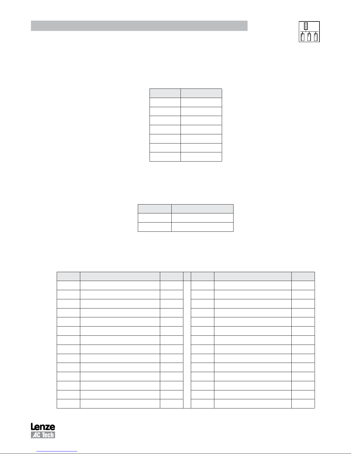
5.4.5 Speed Command Source - Registers #24 & 28
Table 14 lists the Speed Command Source (Register #24 byte D5H or Register #28 DH).
Table 14: Speed Command Source
Setting Source
0 ANALOG FREQ.
1 PRESET c40
2 PRESET 1
3 PRESET 2
4 PRESET 3
5 MOP SPEED
6 SERIAL SPEED
5.4.6 Speed Reference Status - Registers #24 & 28
Table 15 lists the Speed Reference Status (Register #24 byte D5L or Register #28 DL).
Table 15: Speed Reference
5.4.7 Present Fault - Registers #24 & 29
Table 16 lists the Present Fault (Register #24 byte D6H of Register #29 DH)
Setting Fault Display Setting Fault Display
0 NO FAULT 14 INTERNAL FAULT 5 F5
1 OUTPUT (TRANSISTOR) FAULT OC1 15 INTERNAL FAULT 6 F6
2 HIGH DRIVE TEMPERATURE OH 16 INTERNAL FAULT 7 F7
3 HIGH DC BUS VOLTAGE OU 17 INTERNAL FAULT 8 F8
4 LOW DC BUS VOLTAGE LU 18 INTERNAL FAULT 9 F9
5 THERMAL OVERLOAD OC6 19 INTERNAL FAULT o Fo
6 CONTROL FAULT CF 20 SINGLE PHASE FAULT SF
7 EXTERNAL FAULT EEr 21 INCOMPATIBILITY FAULT cF
8 SERIAL COMMUNICATION FAILURE FC5 22 DYNAMIC BRAKE OVERHEATED dF
9 START ERROR LC 23 REMOTE KEYPAD FAULT JF
10 INTERNAL FAULT 1 (EPM) F1 24 COMMUNICATION FAULT FC3
11 INTERNAL FAULT 2 F2 25 EARTH FAULT OC2
12 INTERNAL FAULT 3 F3 26 CONFIGURATION FAULT CFG
13 INTERNAL FAULT 4 F4
Setting Status
0 SERIAL SPEED REFERENCE
1 LOCAL SPEED REFERENCE
Table 16: Present Fault
17 RG-SDMOD
Page 22
Drive Control & Communication
Phone: 800.894.0412 - Fax: 888.723.4773 - Web: www.clrwtr.com - Email: [email protected]
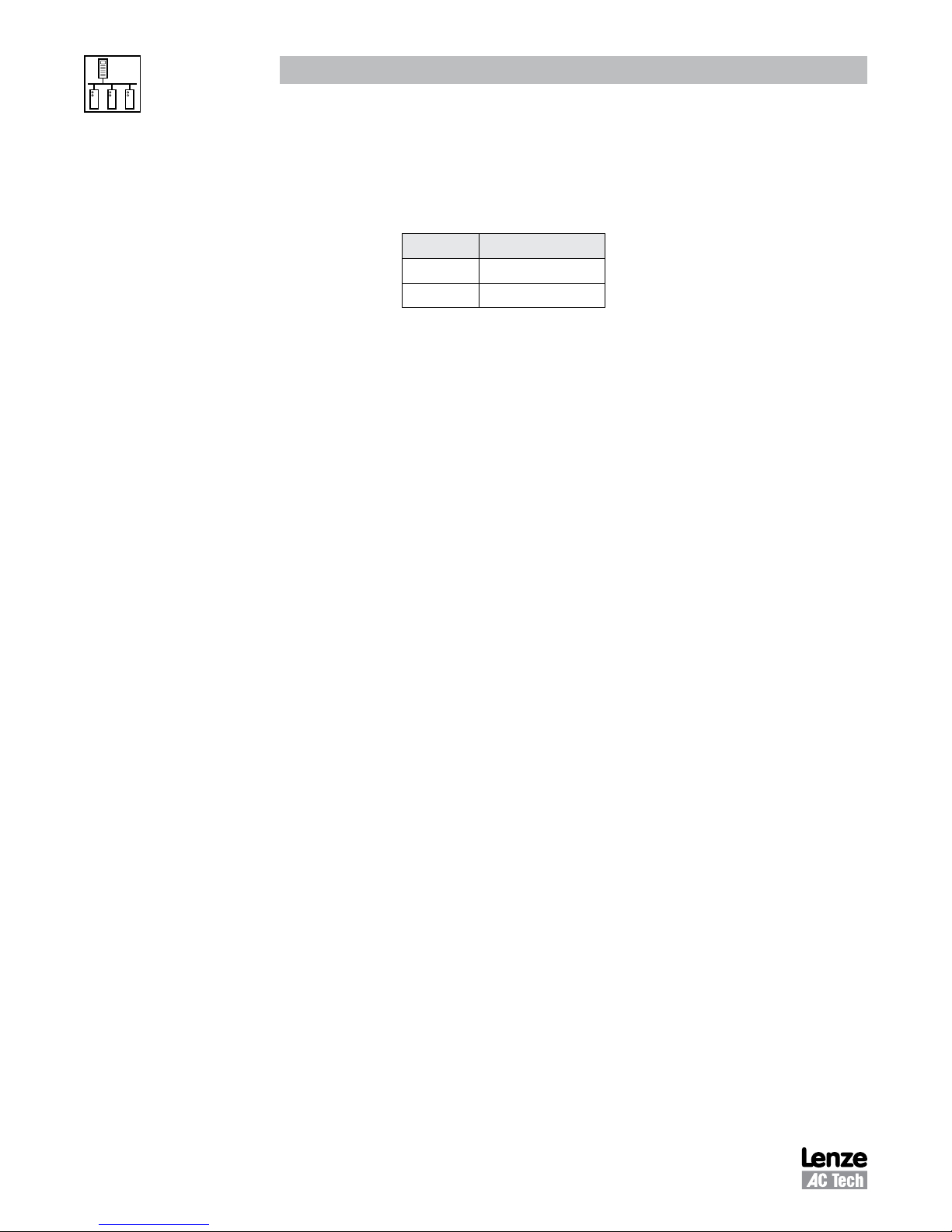
5.4.8 Commanded Rotational Direction - Registers #24 & 29
Table 17 lists the Commanded Rotational Direction (Register #24 byte D6L or Register #29 DL)
Table 17: Commanded Rotational Direction
Setting Direction
0 FORWARD
1 REVERSE
5.5 Motor Volts - Register #30
Output Voltage to the motor expressed as a percentage of nominal drive voltage.
5.6 Serial Speed - Register #40
This register enables the user to set the serial speed to desired value.
• In tenths of a Hz
• Most significant byte is first, followed by Least significant
• CONTROL OF THE DRIVE SPEED VIA THE SERIAL LINK IS NORMALLY DONE USING THIS PARAMETER.
This register can be written only after enabling parameter writes.
• To use this register, SPEED REFERENCE must be set to SERIAL SPEED REFERENCE by setting bit 8 in
control register #1.
5.7 Unlock Commands - Register #48
Register #48 (Unlock Commands) unlocks commands by using 0000 for the password. If the correct
Programming mode password (C94) is entered then the appropriate programming parameters can also
be accessed (refer to the full parameter protocol specification if access to programming parameters is
required).
5.8 Unlock Parameters - Register #49
Register #49 (Unlock Parameters) unlocks programming parameters for writing when the proper
Programming Password (C94) is entered. Whenever a parameter writing session (where #49 was activated)
is to be ended, register #1 bit 1 (Lock Security) must be asserted. This disables the watchdog and prevents
further write access to Parameter Registers.
5.9 Register Version
Register Version is the number to identify if current version of software has any register changes relative
to previous versions: a register has been added or deleted, a register’s min/max limits have changed, a
register’s function has been changed, or a register’s default value has been changed. Generally it is the
programming parameters that are changed. Typically the Control Registers (
are quite stable.
smd
Register #1 through #50)
RG-SDMOD 18
Page 23
Drive Control & Communication
Phone: 800.894.0412 - Fax: 888.723.4773 - Web: www.clrwtr.com - Email: [email protected]
6
smd
Programming Parameters
6.1 Format
Abbreviations:
SA (1byte) Drive Address (1-247)
RA (1byte) Register Address
CRCH Cyclic Redundancy Check High byte
CRCL Cyclic Redundancy Check Low byte
READING:
Message structure for reading 1 word: (most of parameters)
NOTE - Attention
Parameter list presented in Section 6.2 is valid only for
507. For revisions, refer to appropriate
Request: SA 03 00 RA 00 01 CRCH CRCL
Response: SA 03 02 DH DL CRCH CRCL
smd
Manual.
smd
parameter version 400 and
Message structure for reading 4 word: (Parameter C99 Software Version)
Request: SA 03 00 RA 00 04 CRCH CRCL
Response: SA 03 08 D1H D1L D2H D2L D3H D3L D4H D4L CRCH CRCL
WRITING:
Message structure for writing 1 word: (all parameters)
Request: SA 06 00 RA DH DL CRCH CRCL
Response: SA 06 00 RA DH DL CRCH CRCL
LEGEND for Parameter List
1
1st Column: Parameter No.
4th Column: Range of Adjustment 2 = Selections in bold are for
= Drive's programming code number
smd
models with PV507 only.
19 RG-SDMOD
Page 24
Drive Control & Communication
Phone: 800.894.0412 - Fax: 888.723.4773 - Web: www.clrwtr.com - Email: [email protected]
6.2 Parameter List
1
Parameter No.
C01 51 (33H) 51 (33H) Setpoint and Control
C02 52 (34H) 52 (34H) Load Lenze setting 0 No action/loading complete
CE1
CE2
CE3
smd
Register #
(hexadecimal
representation)
PV400 PV507
53 (35H)
54 (36H)
55 (37H)
53 (35H)
54 (36H)
55 (37H
Parameter Name Range of Adjustment
Modbus value (decimal value)
Speed Control Program
Source
Configuration
Digital Inputs
E1, E2, E3
0 Analog Terminal Keypad
1 c40 Terminal Keypad
2 Analog Terminal LECOM
3 LECOM LECOM LECOM
4 Analog Terminal Remote Keypad
5 c40 Terminal Remote Keypad
6 Analog Remote Keypad Remote Keypad
7 c40 Remote Keypad Remote Keypad
8 Analog Terminal Modbus
9 c40 Terminal Modbus
10 Analog Modbus Modbus
11 c40 Modbus Modbus
1 Load 50Hz Defaults
2 Load 60Hz Defaults
3 Load OEM Defaults
4 Translate compatible EPM
NOTE: Drive must be in OFF or Inhibit state to change
1 Activate fixed setpoint 1 (JOG1)
2 Activate fixed setpoint 2 (JOG2)
3 DC Braking (DCB)
4 Direction of Rotation
5 Quick Stop
6 CW Rotation
7 CCW Rotation
8 UP
9 DOWN
10 TRIP set
11 TRIP reset
12 Accel/decel 2
13 Deactivate PI
14 Activate fixed PI setpoint 1
15 Activate fixed PI setpoint 2
2,
Factory
Default
0
0
CE1 = 1
CE2 = 4
CE3 = 3
1 = The drive's programming code number; 2 = Selections in bold are for
smd
models with PV507 only.
RG-SDMOD 20
Page 25
Drive Control & Communication
Phone: 800.894.0412 - Fax: 888.723.4773 - Web: www.clrwtr.com - Email: [email protected]
1
smd
Register #
(hexadecimal
Parameter Name Range of Adjustment
Modbus value (decimal value)
2,
Factory
Default
representation)
PV400 PV507
Parameter No.
C08 57 (39H) 57 (39H) Configuration
Relay Output
0 Ready
1 Fault
1
2 Motor is running
3 Motor is running - CW rotation
4 Motor is running - CCW rotation
5 Output frquency = 0Hz
6 Frequency setpoint reached
7 Threshold (C17) exceeded
8 Current limit reached
9 Feedback within min/max alarm range
10 Feedback outside min/max alarm range
C09 58 (3AH) 58 (3AH) Network Address 1 - 247 1
C10 59 (3BH) 59 (3BH) Minimum Output Freq. 0 - 2400 (0.0 - 240 Hz) 0.0 Hz
C11 60 (3CH) 60 (3CH) Minimum Output Freq. 75 - 2400 (7.5 - 240 Hz) 50.0 Hz
C12 61 (3DH) 61 (3DH) Acceleration Time 0 - 9990 (0.0 - 999 sec) 5.0 sec
C13 62 (3EH) 62 (3EH) Deceleration Time 0 - 9990 (0.0 - 999 sec) 5.0 sec
C14 63 (3FH) 63 (3FH) Operating Mode 0 Linear with Auto Boost
2
1 Square Law with Auto Boost
2 Linear with Constant V
3 Square Law with Constant V
min
Boost
min
Boost
C15 64 (40H) 64 (40H) V/f Reference Point 250 - 9990 (25.0 - 999 Hz) 50.0 Hz
C16 65 (41H) 65 (41H) V
Boost 0 - 400 (0.0 - 40.0%) 4.0%
min
C17 66 (42H) 66 (42H) Frequency Threshold 0 - 2400 (0.0 - 240 Hz) 0.0 Hz
C18 67 (43H) 67 (43H) Chopper Frequency 0 4kHz
2
1 6kHz
2 8kHz
3 10kHz
C21 68 (44H) 68 (44H) Slip Compensation 0 - 400 (0.0 - 40.0%) 0.0%
C22 69 (45H) 69 (45H) Current Limit 30 - 150% 150%
C24 70 (46H) 70 (46H) Accel Boost 0 - 200 (0.0 - 20.0%) 0.0%
C31 71 (47H) Analog Input Deadband 0 Deadband Enabled
0
1 Deadband Disabled
C34 71 (47H) 72 (48H) Configuration
Analog Input
0 0...10V
1 0...5V
0
2 0...20mA
3 4...20mA
4 4...20mA Monitored
C36 72 (48H) 73 (49H) Voltage (DCB)
0 - 500 (0.0 - 50.0%) 4.0%
DC Injection Brake
C37 73 (49H) 74 (4AH) Fixed Setpoint 1 (JOG1) 0 - 9990 (0.0 - 999) 20.0 Hz
smd
1 = The drive's programming code number; 2 = Selections in bold are for
models with PV507 only.
21 RG-SDMOD
Page 26
Drive Control & Communication
Phone: 800.894.0412 - Fax: 888.723.4773 - Web: www.clrwtr.com - Email: [email protected]
1
smd
Register #
(hexadecimal
Parameter Name Range of Adjustment
Modbus value (decimal value)
2,
Factory
Default
representation)
PV400 PV507
Parameter No.
C38 74 (4AH) 75 (4BH) Fixed Setpoint 2 (JOG2) 0 - 9990 (0.0 - 999) 30.0 Hz
C39 75 (4BH) 76 (4CH) Fixed Setpoint 3 (JOG3) 0 - 9990 (0.0 - 999) 40.0 Hz
C46 78 (4EH) 79 (4FH) Frequency Setpoint 0 - 2400 (0.0 - 240 Hz) Read Only
C50 79 (4FH) 80 (50H) Output Frequency 0 - 2400 (0.0 - 240 Hz) Read Only
C52 80 (50H) 82 (52H) Motor Voltage 0 - 255% Read Only
C53 81 (51H) 83 (53H) DC Bus Voltage 0 - 255% Read Only
C54 82 (52H) 84 (54H) Motor Current 0 - 255% Read Only
C56 83 (53H) 85 (55H) Drive Load 0 - 255% Read Only
C59 86 (56H) PI Actual Feedback c86 - c87 Read Only
C70 89 (59H) PI Proportional Gain 0 - 999 (0 - 99.9%) 5.0%
C71 90 (5AH) PI Integral Gain 0 - 999 (0 - 99.9 sec) 0.0 sec
C90 86 (56H) 92 (5CH) Input Voltage Selection 0 Auto
0
1 Low
2 High
C94 88 (58H) 94 (5EH) User Password 0 - 999 0
C99 89 (59H) 95 (5FH) Software Version Read 4 words (format 'SMD 1.51') Read Only
c01 96 (60H) Accel Rate 2 0 - 9990 (0.0 - 999 sec) 5.0 sec
c03 97 (61H) Decel Rate 2 0 - 9990 (0.0 - 999 sec) 5.0 sec
c06 90 (5AH) 98 (62H) Holding Time - Auto
0 - 9990 (0.0 - 999 sec) 0.0 sec
DC Injection Brake
c08 91 (5BH) 99 (63H) Analog Output Scaling 10 - 9990 (1.0 - 999) 100.0
c11 92 (5CH) 100 (64H) Configuration
Analog Output (62)
0 None
1 Output frequency 0 - 10V
0
2 Output frequency 2 - 10V
3 Load 0 - 10V
4 Load 2- 10V
5 Dynamic Braking
c17 93 (5DH) 101 (65H) Configuration
Digital Output (A1)
0 Ready
1 Fault
0
2 Motor is running
3 Motor is running - CW rotation
4 Motor is running - CCW rotation
5 Output frquency = 0Hz
6 Frequency setpoint reached
7 Threshold (C17) exceeded
8 Current limit reached
9 Feedback within min/max alarm range
10 Feedback outside min/max alarm range
2
c20 94 (5EH) 102 (66H) I
T Switch-Off 30 - 100% 100%
smd
1 = The drive's programming code number; 2 = Selections in bold are for
models with PV507 only.
RG-SDMOD 22
Page 27
Drive Control & Communication
Phone: 800.894.0412 - Fax: 888.723.4773 - Web: www.clrwtr.com - Email: [email protected]
1
Parameter No.
c25 95 (5FH) 103 (67H) LECOM Baud Rate 0 9600 bps (9600, 8, N, 2 if C01 = 8...11)
c38 105 (69H) PI Actual Setpoint c86 - c87 Read Only
c40 97 (61H) 106 (6AH) Freq. Setpoint Command 0 - 2400 (0.0 - 240 Hz) 0.0 Hz
c42 98 (62H) 107 (6BH) Start Condition 0 Start after LOW-HIGH chnage at 28
c60 109 (6DH) Mode Select for c61 0 Monitor Only
c61 100 (64H) 110 (6EH) Present Fault Status / Error Message (refer to Note 5) Read Only
c62 101 (65H) 111 (6FH) Last Fault Error Message (refer to Note 5) Read Only
c63 102 (66H) 112 (70H) Last but one Fault Error Message (refer to Note 5) Read Only
c70 103 (67H) 113 (71H) Configuration
c71 104 (68H) 114 (72H) Auto TRIP Reset Delay 0 - 600 (0.0 - 60.0 sec) 0.0 sec
c78 105 (69H) 115 (73H) Operating Time Counter Read Only
c79 106 (6AH) 116 (74H) Mains Conn Time Counter Read Only
c81 117 (75H) PI Setpoint c86 - c87 0.0
c82 118 (76H) S-Ramp Integral Time 0 - 500 (0.0 - 50.0 sec) 0.0 sec
c86 119 (77H) PI Min Feedback 0 - 9990 (0.0 - 999.0) 0.0
c87 120 (78H) PI Max Feedback 0 - 9990 (0.0 - 999.0) 100.0
d25 123 (7BH) PI Setpoint Accel/Decel 0 - 9990 (0.0 - 999.0 sec) 5.0 sec
d38 124 (7CH) PI Enable 0 PI Disabled
d46 125 (7DH) PI Min Alarm 0 - 9990 (0.0 - 999.0) 0.0
d47 126 (7EH) PI Max Alarm 0 - 9990 (0.0 - 999.0) 0.0
n20 113 (71H) 131 (83H) LECOM Power-Up State 0 Quick Stop
n22 114 (72H) 132 (84H) Serial Timeout Action 0 Not Active
n23 115 (73H) 133 (85H) Serial Fault Time 50 - 65535 ms 50 ms
smd
Register #
(hexadecimal
representation)
PV400 PV507
Parameter Name Range of Adjustment
Modbus value (decimal value)
1 4800 bps (9600, 8, N, 1 if C01 = 8...11)
2 2400 bps (9600, 8, E, 1 if C01 = 8...11)
3 1200 bps (9600, 8, O, 1 if C01 = 8...11)
1 Auto Start if 28 = HIGH
1 Monitor and Edit
0 TRIP reset by LOW-HIGH signal at 28 or mains
TRIP Reset
switching or LOW-HIGH signal at digital input
"TRIP reset"
1 Auto TRIP reset
1 PI Enabled - Normal Acting
2 PI Enabled - Reverse Acting
1 Inhibit
1 Controller Inhibit
2 Quick Stop
3 Trip Fault "FC3"
2,
Factory
Default
0
1
0
0
0
0
0
smd
1 = The drive's programming code number; 2 = Selections in bold are for
models with PV507 only.
23 RG-SDMOD
Page 28
Drive Control & Communication
Phone: 800.894.0412 - Fax: 888.723.4773 - Web: www.clrwtr.com - Email: [email protected]
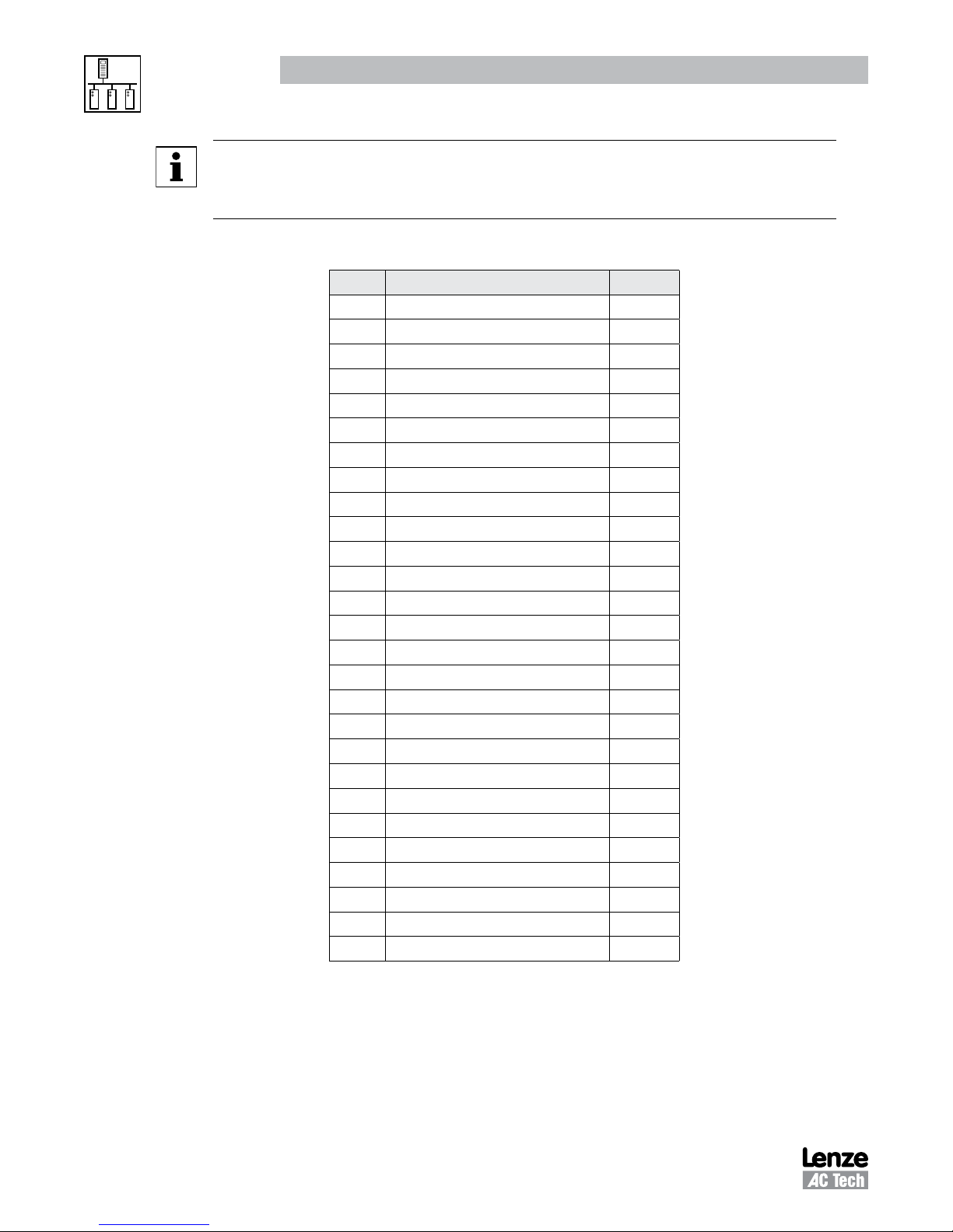
NOTE 5 -
smd
- Fault History
Parameters c61 (Present Fault), c62 (Last Fault) and c63 (Last but one Fault) provide the
Fault History for the
smd
drive. Table 18 lists the fault codes.
Table 18: Fault Codes - c61, c62 & c63
Code Fault Description Display
0 NO FAULT
1 OUTPUT (TRANSISTOR) FAULT OC1
2 HIGH DRIVE TEMPERATURE OH
3 HIGH DC BUS VOLTAGE OU
4 LOW DC BUS VOLTAGE LU
5 THERMAL OVERLOAD OC6
6 CONTROL FAULT CF
7 EXTERNAL FAULT EEr
8 SERIAL COMMUNICATION FAILURE FC5
9 START ERROR LC
10 INTERNAL FAULT 1 (EPM) F1
11 INTERNAL FAULT 2 F2
12 INTERNAL FAULT 3 F3
13 INTERNAL FAULT 4 F4
14 INTERNAL FAULT 5 F5
15 INTERNAL FAULT 6 F6
16 INTERNAL FAULT 7 F7
17 INTERNAL FAULT 8 F8
18 INTERNAL FAULT 9 F9
19 INTERNAL FAULT o Fo
20 SINGLE PHASE FAULT SF
21 INCOMPATIBILITY FAULT cF
22 DYNAMIC BRAKE OVERHEATED dF
23 REMOTE KEYPAD FAULT JF
24 COMMUNICATION FAULT FC3
25 EARTH FAULT “OC2”
26 CONFIGURATION FAULT “CFG”
RG-SDMOD 24
Page 29
7
Phone: 800.894.0412 - Fax: 888.723.4773 - Web: www.clrwtr.com - Email: [email protected]
Initial Settings
These instructions are for basic start, stop direction and speed control of the smd drive using Modbus
communication.
1. Set Drive Parameter C01 to 11.
2. Set Drive Parameter C09 to the desired network address that the Modbus master will poll. Valid Modbus
addresses are 1-247.
TIP - Avoid using address 1. Most Modbus devices ship with a default address of 1. As duplicate
addressing on a Modbus network is not allowed, this can lead to conflicts when replacing and
commissioning nodes. To avoid this it is recommended that you do not set the slave address to 1.
3. The Modbus master needs to be set to use 9600 baud. No other baud rates are supported by the SMD
drive.
Drive Control & Communication
4. The SMD series drive has the provision for a watchdog timer to monitor network communications to
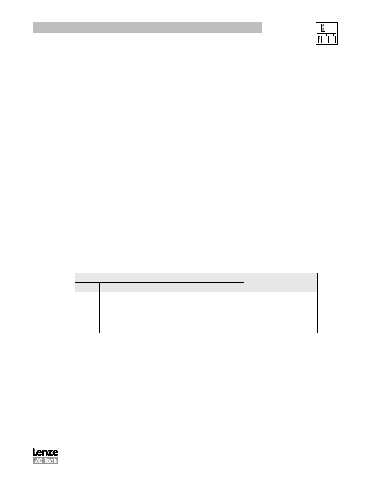
the drive. The drive’s timeout behavior is set using Parameter n22 and the timeout period is set using
Parameter n23 as shown in Table 19.
Table 19: Watchdog Timer
Code Possible Settings Important
No. Name Lenze Selection
n22 Serial Timeout Action 0 0 Not Active
1 Controller Inhibit
2 Quick Stop
3 Trip Fault "FC3"
n23 Serial Fault Time 50 50 - 65535 ms Sets the serial timeout length
Selects controller reaction to
serial timeout
Set n22 and n23 as appropriate for the application:
5. The drive needs to have its network data formatting set the same as the Modbus master.
a. If the Modbus master is set to use 8 data bits, no parity and two stop bits, set c25 to 0.
b. If the Modbus master is set to use 8 data bits, no parity and one stop bit, set c25 to 1.
c. If the Modbus master is set to use 8 data bits, even parity and one stop bit, set c25 to 2.
d. If the Modbus master is set to use 8 data bits, odd parity and one stop bit, set c25 to 3.
25 RG-SDMOD
Page 30

7.2 Drive Control
Phone: 800.894.0412 - Fax: 888.723.4773 - Web: www.clrwtr.com - Email: [email protected]
1. Please be advised that while the drive is under network control the local STOP circuit is always enabled.
Input 28 needs to be asserted in order for the drive to start. If you will not be using start/stop simply
jumper TB28 input to TB20.
2. Use either Modbus function code 16 with a length of 1 or Modbus function code 06 to perform any
writes to the drive.
3. Unlocking the Drive.
The first write necessary to the drive to perform any function (start,change speed, change a parameter,
etc) needs to be an unlock.
If you want to both control the drive and alter any programming parameters then write the drive’s
programming password to Modbus register 40049. The default password for the SMD drive is 0.
You should only need to send the unlock command once after power up. As long as the communications
do not timeout you should not need to write another unlock to the drive before writing any other
function.
Drive Control & Communication
4. Setting the Drive to Network Speed reference:
In order for the drive to respond to speed commands written to the keypad speed register the drive
must be put into manual mode. To do this write a value of 100H to Modbus register 40002 (the drive’s
control register).
7.3 Basic Drive Commands
The following are the basic drive commands. ONLY ONE OF THESE CAN BE DONE AT A TIME:
1. To STOP the drive using COAST TO STOP, write a value of 0004hex to Modbus register 40002 (AC Tech
register 1).
2. To Start the drive write a value of 0008hex to Modbus register 40002.
3. To Set Reverse direction write a value of 0040hex to Modbus register 40002.
4. To Set Forward direction (the drive powers up with forward direction already selected) write a value of
0080hex to Modbus register 40002.
5. If you want the network to control speed of the drive, write the speed to the Serial Speed Command
Register, Modbus register 40041 (AC Tech register 40). Speed is written in 0.1Hz (so 412 would be
41.2 Hz). In this mode the drive’s initial speed reference on power up will be the last speed written to
the drive.
RG-SDMOD 26
Page 31
Drive Control & Communication
Phone: 800.894.0412 - Fax: 888.723.4773 - Web: www.clrwtr.com - Email: [email protected]
7.4 Basic Drive Status
AC Tech register 24 is a 6 word entity containing the drive’s status information. To read the entire status
block use Modbus function code 3 with a length of 6 to read starting at Modbus register number 40025.
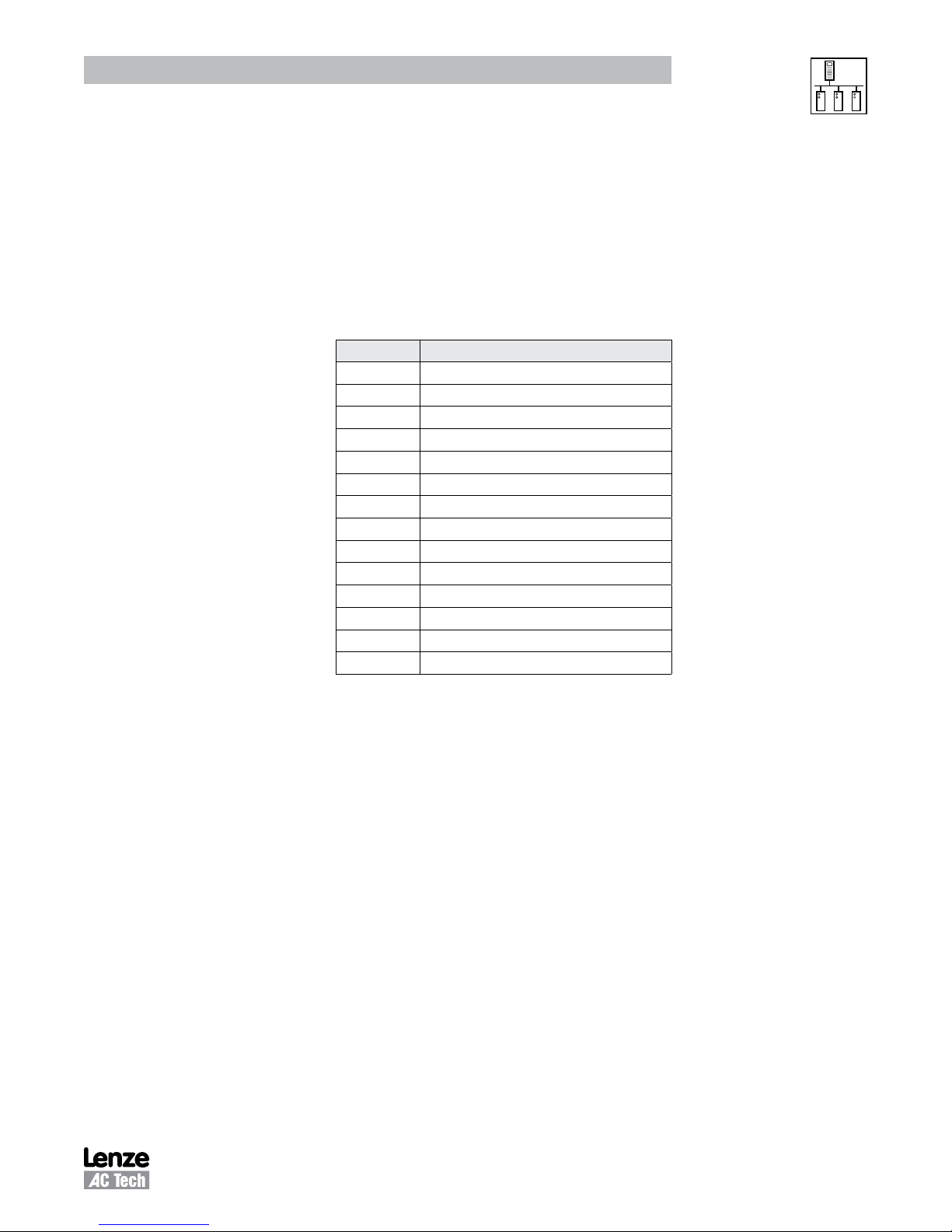
The low byte of the third word in this block of data contains the operational status. If this is the only data
you want you can use Modbus function code 3 with a length of 1 to read register 40027.
The value of that low byte of data corresponds to the following operational states:
Table 20: Operational Status
Bit Parameter
0 FAULT LOCKOUT
1 FAULT
2 START PENDING
3 STOP
4 DC BRAKE
5 RUN AT 0Hz
6 RUN
7 ACCEL
8 DECEL
9 CURRENT LIMIT
10 DECEL OVERRIDE
11 LOWER TRANSISTORS SWITCHING ON
12 OFF
13 INHIBIT
27 RG-SDMOD
 Loading...