

Page 1
Page 2
ET46/fa
checked:
19.04.89
~I4B
33.0831
GB
page:
1
Table
1.
2.
3.
4.
5.
5.1
5.1.1
5.1.2
5.1.3
5.2
5.3
5.4 Selectiori of
5.5
5.6
5.7
5.8
5.9
5.10
5.11
5.12
5.13
5.14
5.15
of
conterits
Features
Specifications
Conriecting
Installation
Conriectirig
External
Using
Using master
Using
Controllerinhibit
Reversing
External
External TRIP
Switching
Standstill
‚Identical
Overload
TRIP
Frequencyoutput
I4ains
Motor
Connection
set-value
poteritioxrieter
current
temperature
indication
relay
connection
connection
diagram
instructions
instructions
adjustment
voltage
loop
and
brakirig
tixed
reset
of
the
iridication
freguency“ indication
of
braking
control
frequencies
switch
acceleration
resistor(s)
(speeds)
and
deceleration
ramp
page
2
2
3
4
4
4
4
4
4
5
5
6
7
7
7
8
8
9
9
10
10
11
11
6.
7.
7.1
7.2
7.3
8.
9.
10.
11.
12.
Display and
Modification
Keyboard
Furiotion
Description
Fault
Dimensionsand weights
Mains
Semiconductor
Braking
?.ad%o
1;ems
diagnosis
chokes
i::terfe~er~ce
:bers
supp1i~
operating
of
operation
code
of
the function
fuses
resistors
Ii
factory-set
suD~‘reE:i1Qn
and
panel
fuse
paraineters
code
holders
12
13
13
14
15
27
28
29
30
31
32
32
Page 3
ET4
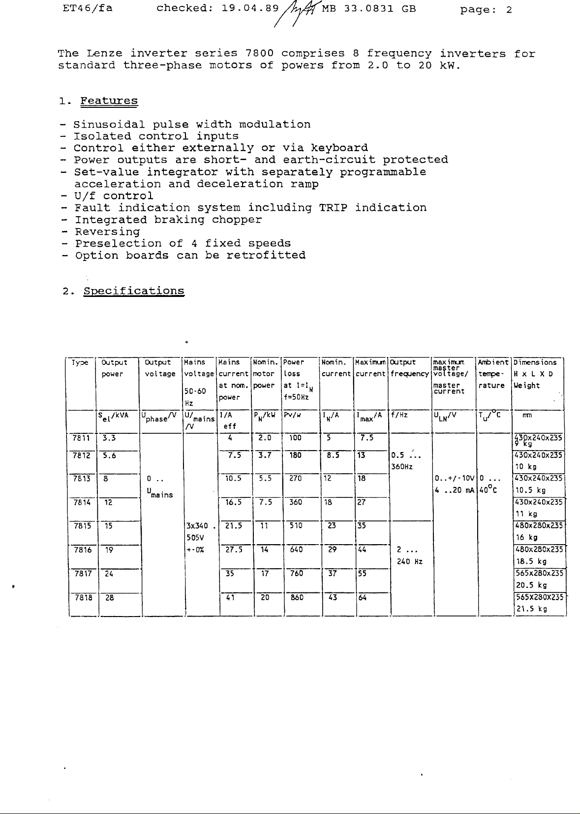
The
6/fa
Lenze
checked:
inverter
19.04.89
series
standard three-phasemotors
1.
Features
-
Sinusaidal
-
Isolated
-
Contro3.
-
Power outputs
-
Set-value
acceleration
-
U/f
control
-
Fault
-
Tntegrated braking chopper
-
Reversirig
-
Preselection
-
Option boards
2.
Specifications
indication
pulse
contro3.
either
integrator
and
of
width
inputs
externally
are
short—
with
deceleration
system
4
fixed
can
be
inodulation
retrofitted
~MB
7800
comprises
of
powers from
or
via
and
earth-circuit
separately
ramp
including
speeds
33.0831
8
keyboard
prograininable
TRIP
GB
page:
frequency inverters
2.0 to
20
kW.
protected
indication
2
for
Ty~e
7811
7&12
7813
7814
7815
7816
7817
7818
O.vtput
power
S
/kVAetU
3.3
5.6 7.5
8
12
15
19
24 35 17
28 41
Output
voltage
/V
phase
0
..
lJ
Mains
vottage
50-60
Hz
U/
-
mains
/V
3x340
505V
4-Q%
Hains
current
at
norn.
power
hA
eff
4
10.5
3
16.5
21.5
.
27.5
Nomin.
Power
motor
power
at
p
/kWNPv/w
2.0
3.7
5.5 270
7.5 360
11
14
20
Loss
1=1
f=5OHz
100
180
510
640
760
8.60
Nca~in.
current
1
IA
5
8.5
112
118
1
23 35
29 44
37
43 64
Maxin~j¶~
current
1
13
18
27
55
max
7.5
Output
/A
frec~~ency
f/Hz
0.5
...
360Hz
2
...
240
Hz
maxifrLrn
ma
ter
vo?t
age!
master
current
ULN/V
0.
.+/-10V
4
..20
rnA
Ant~ient
teaperature
iL7~W
0
...
0C
40
Dimensions
HxL X
ljeight
~3~x240x235
•430x240x2.35
10
430x240x235
10.5
430x240x235
11kg
480x280x235
16
480x280x235
18.5
565x280x235
20.5
565X280X235
21.5
0
kg
kg
kg
kg
kg
kg
Page 4
ET4
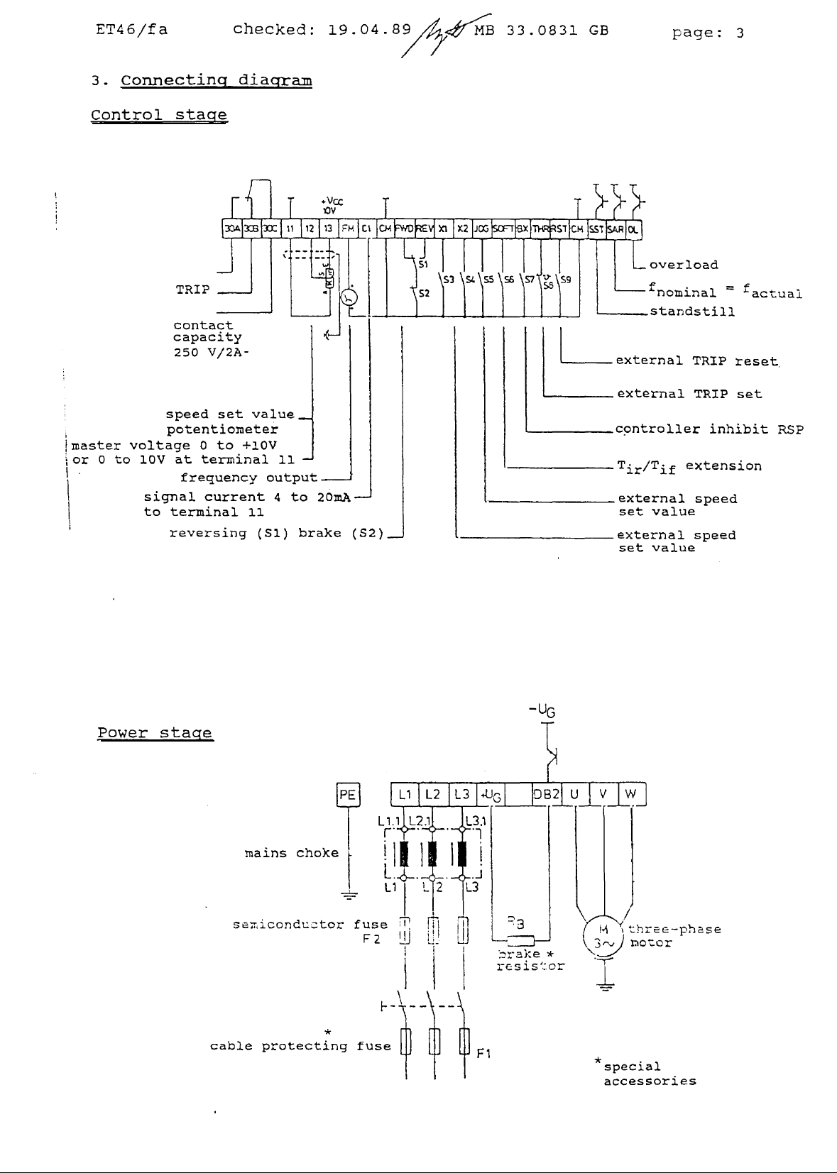
3.
Connecting
6/fa
checked:
diagram
19.04.89
33.0831
GB
page:
3
Control
Lmnaster
or0to
stage
TRIP
contact
capacity
250
speed
potentio~eter
voltage
10V
sigriaj.
to
0
at
teni-~inal
terDlirlal
reversing
V/2A-
set
value
to
+10V
current
11
(S1)
__
11
—
4
to 2OmA
brake
(S2)
overload
~nomina).
standstill
externaj.
external
controller
Tir/Tif
external speed
set
external
set
TRIP
TRiP
inhibit
extension
value
speed
value
=
reset
set
~actuai
RSP
Power
stage
muains
s~~ccndu~ztor
cable
protectingtuse
choke
-
UG
thret~—ph~se
I~otcr
*
special
accessories
Page 5
ET46/fa
4.
Installation
The
controller
at
the
±
:LOOin~
inaintain
bottom.
at
the
checked:
instructions
should
Ensure that
the top
flow
of
and
air
19.04.89
be
bottain,
maxrmmm ambient temperature
In
case of
rise
inust
fuses
5.
Connectinc~
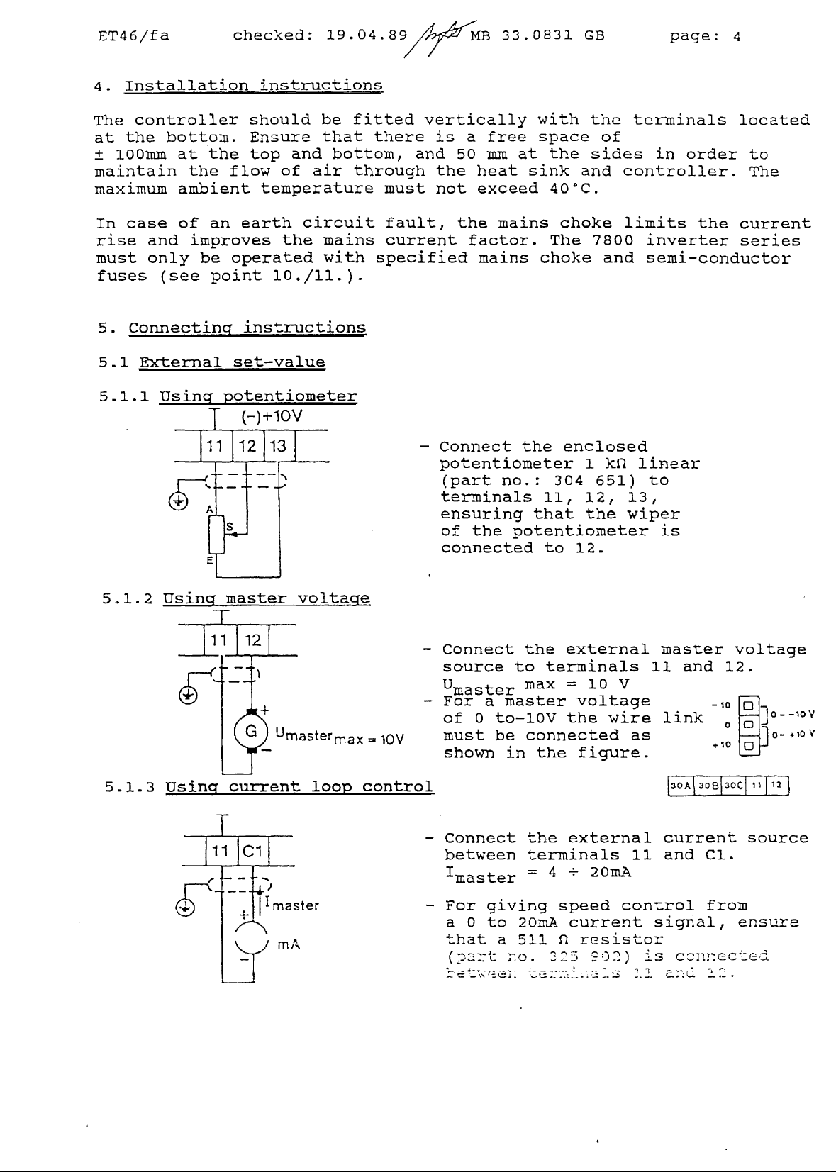
5..l
and
only
(see
External
an
earth
improves
be
operated
paint
instructions
set—value
circuit
the
~nains
with
10./il.).
fitted
vertically
there
and
tI~xrough
must
fault,
current
specif
is
50
the
not
the
led
~4B
a
factor.
33.0831
with the
free
mm
heat sink
exceed
at
mains
space
the
0C.
40
choke
The
mains choke
GB page:
terminals
of
sides
and
7800
and
in
order
controller.
limits
the
inverter
sexni-conductor
4
located
to
The
current
series
5..l.1
5.1.2
5..l..3
Usinc~
Usinq~
potentioxneter
(-)
+10V
UmastermaxiOV
current
loop
control
—
Corrnect
potentiometer
(part
no..:
terminals
ensuring
of
the
connected
—
Connect
source
Umaster
—
For
a master
of
0
to—lOV
must
shown
be
in
the
enclosed
1
kfl
304 651) to
11, 12,
that
the
potentiometer
to
l2~
the external
to
terminals
max
=
10
V
voltage
the
wire
connected
the
figure.
linear
13,
wiper
is
master
11
as
and
link
~f~B3Ocf12
voltage
12.
~
master
—
Connect
between
‚master
-
For
a 0
that
(‚-x=~t
—
the
terminals
=
giving
to
2OmA
a
511
;o.
external
4 ~-
speed
current
fl
resistor
225
20mA
?D2)
current
11
and
control
signal,
is
c~nm-.ccted
-~
—.
source
Cl.
froln
ensure
Page 6
ET4
6/fa
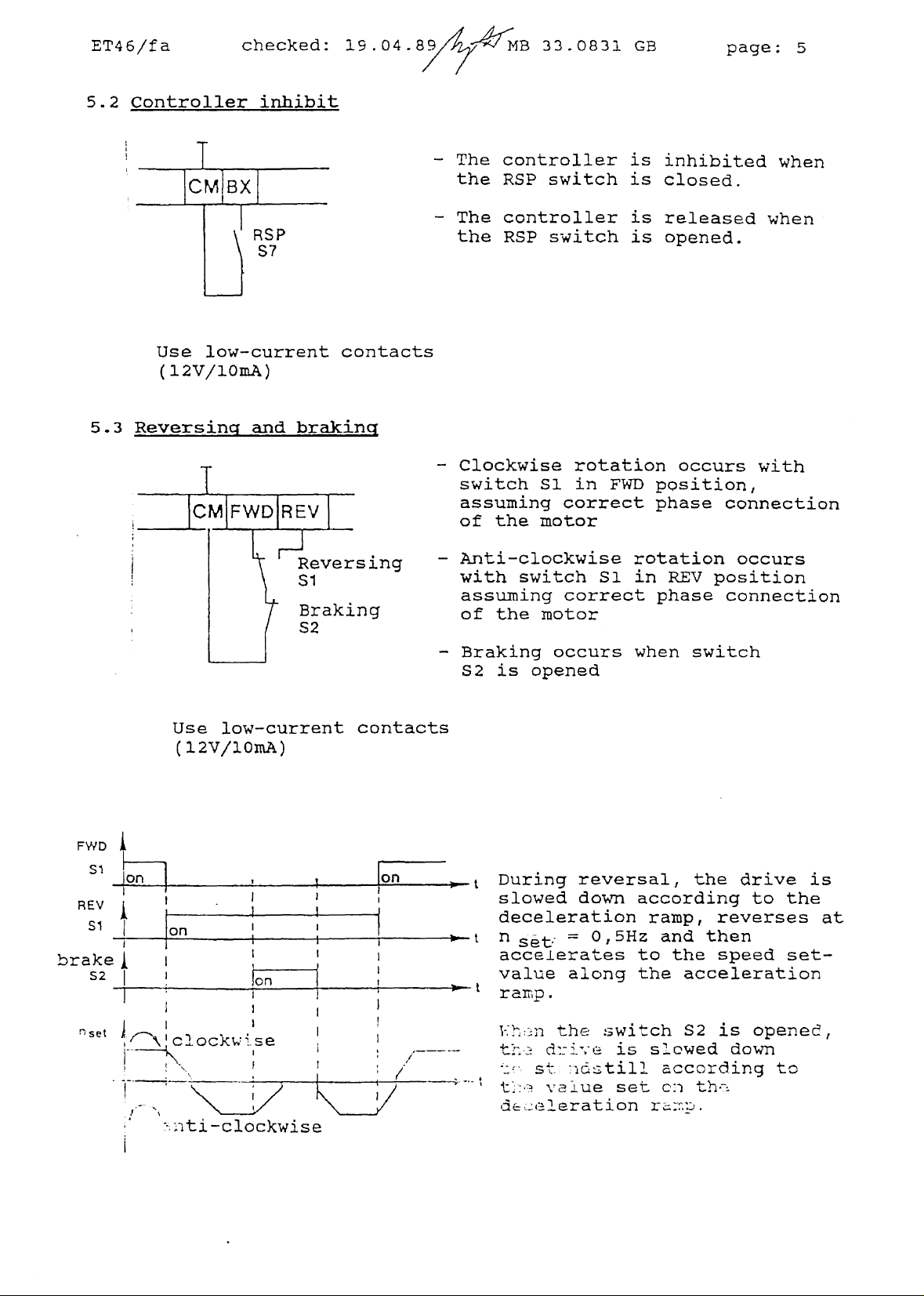
5.2
Controller
checked:
inhibit
RSP
S7
19.04.89
—
The
the
—
The
the RSP
IB
33.0831
controller
RSP
switch
controller
switch
GB
is
inhibited
is
closed.
is
releasedwhen
page:
is operied.
5
when
5.3
USe
low—current
(12V/lOinA)
Reversincr
Use
(12V/lOxnA)
and
low-current
contacts
braking
Reversing
s1
contacts
-
Clockwise
switch
51 in
assuming
of
the
motor
—
Ariti-clockwise
with
switch
assulning
of
the
motor
—
Braking
S2
is
occurs
opened
rotation
FWD
correct
51 in
correct
occurs
with
position,
phase
connection
rotation occurs
REV position
phase
connection
when switch
FWD
SI
-
-
-‚Pn
REV k
si
~
brakej
S2
T
~set ~‚~N‘c1ockw~se
—i-----I-------
fon
1
____
__________
-~
II
,
—‚
~ti-clockwise
Qn
on
—~--t
-1-
During
slowed
deceleration
n
set-
acceierates
value
reversal,
down
according
0,5Hz
to
alcing
the
the
raxop,
and
the
reverses
then
speed
acceleration
drive
to
is
the
at
set—
ramp.
~-2~3rl
—
t~
-~
~
tI--~
th&
~wi~ch S2 is
ci~:fy~iss.owed
-
- - ~L..1¶ ~
s~.
~Q~U1J!
v~1ue
set
down
accoroing
c:~
thr.
openec~,
Page 7
ET4
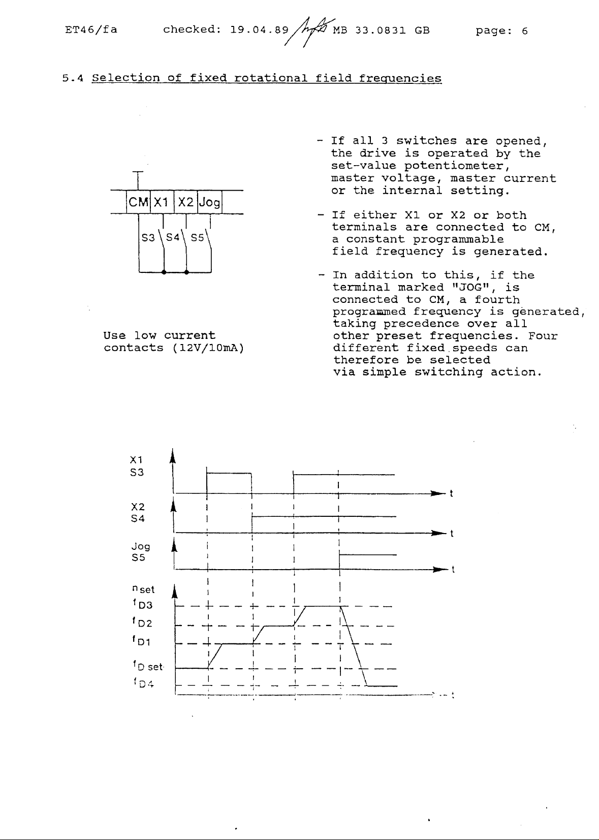
5..4
6/fa
Selection
T
CMIX1
Use
bwcurrent
contacts
checked:
of
fixed
X2
S3 S4 S5
(12V/lOmA)
Jogj
19.04.89
rotational
MB
33.0831
field
-
-
-
frecmencies
lt
all 3
the
drive
set—value
master
or
lt
terminals
a
constant
f
leid
In
terminal
connected
progra~medfreq~uency
taking
other
different
therefore
via
voltage,
the
internal
either Xl or
frequency
addition
preset
simple
GB
switches
is
potentiometer,
are
prograiiuuable
to
marked
to
precedence
fixedspeeds
be
switching
page:
are
operated
master
setting.
X2
or
connected
is
generated.
this,
„JOG“,
CM,
frequencies. Four
selected
a
over
lt
tourth
is
6
opened,
by
the
current
both
to
the
is
generated,
all
can
action.
CM,
xl
S3
X2
S4
Jog
$5
„set
D3
tD2
~D1
~D
D
set
4
lt
f.
1 1
~~~1
t
—
t
Page 8
ET4
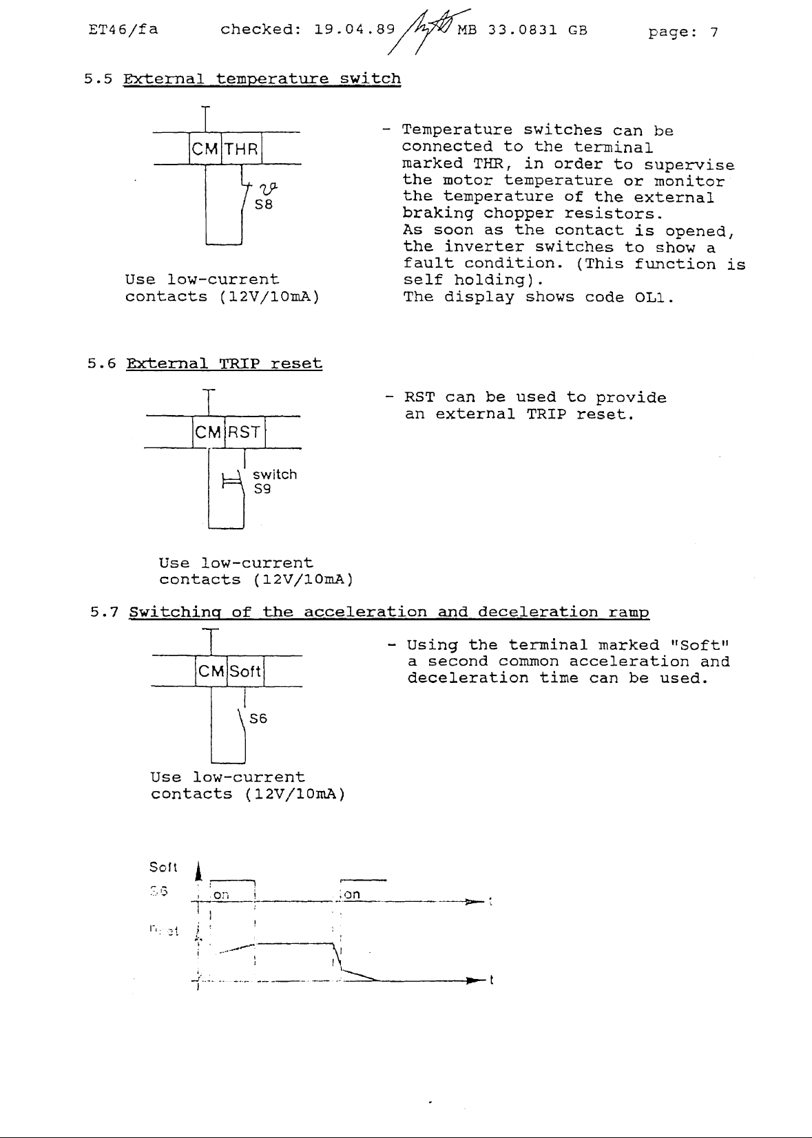
5.5
5.6
6/fa
External
Use
low-current
contacts
Bxternal
checked:
teniperature
79.
S8
(12V/lOmA)
TRIP
reset
T
CMjRSTj
19.04.89
switch
-
Temperature
connected
muarked
the
motor
the
temperature
braking
As
soon
the
inverter
fault
selt
The
display
-
RST
can
an
external
MB
33.0831
to
THIR,
chopper
as
condition.
holding).
be
GB
swltches
the
in
order
temperature
of
resistors.
the
contact
switches
shows
used
to
TRIP
page:
can
be
terminal
to supervise
or
monitor
the external
is
to
(This
f1lnction
code OLl.
provide
reset.
opened,
show
7
a
is
Use
5.7 Switchinq-
Use
low-current
contacts
low—current
contacts
So!
k
of
S6
(12V/lOm.A)
_______
switch
59
(12V/lOmA)
the
accelerationand
-
Using
a
second
deceleration
deceleration
the terminal
common
time
ramp
marked
acceleration
can
be
„Saft“
and
used.
1‘
Page 9
ET4
5.8
6/fa
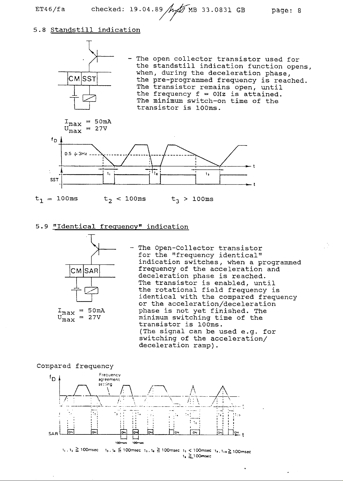
Standstill
checked:
indication
19.04.8>t~/~14B
—
The
open
the
standstill
when,
the
The
the
The
during
pre—programmed
transistor
trequency
minimum
transistor
33.0831
collector
lndication function
the
remains
f
swltch-on
is
lOOms.
transistor
deceleration
frequency
=
0Hz
GB
open,
Is
attained.
tiine
of
page:
used
phase,
is
reached.
until
the
8
tor
opens,
5.9
‚max
Umax
SST
-=
lOOms
~Identical
‚max
Umax
=5OmA
=27V
=27V
<
lOOms
frecruency“
-
The
for the
indication switches,
freguency
deceleration phase
The
the
identical
or
phase
minimum
transistor
(The
switching
deceleration
t
3
>
indication
Open-Ccllector
„frequency
of
transistor
rotational
with the
the
acceleration/deceleration
is
not yet finished. The
switching
Is lOOms.
signal
ot
lOOms
the
is
field
can be
the
ramp).
transistor
identical“
when
a
programmed
acceleration
is
reached.
eriabled,
until
freguency
compared
tlme
of
used
treguericy
the
e.g.
aoceleratlon/
and
is
tor
Compared
1
1
SAR
frequency
.—
O~
-
re.
a~reemer~1
s~
O~.
uer~cy
ing
\
§S
O~
tOO.~c ~O0~‘mc
0
ON
O.~
~m~
1OOfV~sec
Page 10
ET4
6/fa
checked: 19.04.89 MB
33.0831
GB
page:
9
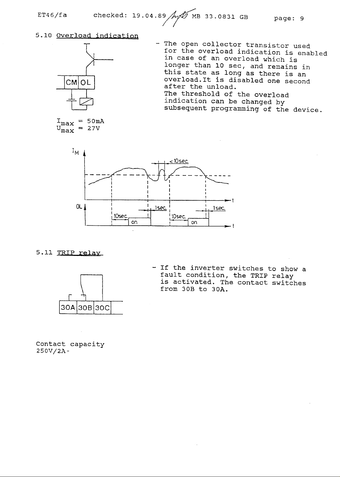
5.10
Qverload
indication
‚max SOmA
Umax
=27V
-
The
open
tor the
in
case
langer than
this
overload
of
state
collector
an
as
overload.It
after the unload.
The
threshold
indication
subseguent
can
programming
indication
overload
10 sec,
long
is
disabled
of
the
be
transistorused
is
as
and
which
remains
there
is
is
one second
overload
changed
ot
by
the
device.
enabled
in
an
5.11
TRIP
[3oA13
Coritact
250V/2A-
OL
relav
F
OB
1300
capacity
-
lt
the
fault
is
activated.
from
30B
inverter
condition,
The
to 30A.
switches
the
to
show
TRIP relay
contact switches
a
Page 11

ET46/f
a
checked:
19.04.89
MB
33.0831
GB
page:
10
5.12
a)
b
Frecruericv
Analogue
1
Digital
OMEM
885
out~ut
M
~7
C2H1-
4~1
5
-
An analogue
can
be
connected
which
or
0
0 —
is
—
10V tor
10V
used
Adjustment using
—
A
suitable
a
VSC
analogue meter,
-
A
digital
be
connected
~FM
~FM
Such
be a
=
=
=
a
322
display
24xfD
l2XfD
GXfD at
suitable
unit,
measuring
to
monitor:
0
+
tor
0
—
trlmmer
measuring
giving:
at
~D~{AX
at
tDI
fD~~<=200Hz
digital
part
instrument
(Ri
=
10km)
60HZ
120Hz
instrument
part
device
50Hz
4AX=lOOHz
no.
ADJ
no.
can
or
or
or
meter
326
is
326 893
also
60Hz
120Hz
240Hz
would
884
5.13
lt
3
minutes
Mains
PE
the
connection
L1
L2
motor
(e.g.
FU
7800
L3
must
jogging),
be
released
-
L1, L2,
340 to
-
Semiconductor
mains
tables
-
On-otf
limited
within
the
following
L3
505V
chokes
on
pages
mains
to
periods
three-phases
±
0%.
fuses
are
and
speclfied
30/31.
switching
once
circuit
in
every
of
less than
must
should
3
be
=
RFR
In
the
be
minutes.
used.
Kl~j~
K2(j
K44D
motor
K24J
Bx
Page 12

ET4
6/fa
checked:
19.04.89
MB
33.0831
GB
page:
II
5.14
‚~
screened
motor
(*)
levels
VDE
Motor
cable
three-phase
Valid
ot
0871.
corYnection
motor
tor
radio
industrial
interferencesuppression
lt necessary,
3
plants
please
—
Ihe
nominal
normally selected
corresponds
nominal
e.g.
—
lt
exceeds
voltage,
the
mains voltage
380V
460V
motor
motor
nominal
the
the inverte.r‘soutput
characteristic
grammed
turietion
—
Switching
as
code
of
permissible
described
and
factories
under polnt
in
consult the
motor
voltage
such
to
the
available
at
380V
at
460V
mains
voltage
nominal motor
can
be
described
urider
10.
the
phases
with
the
which
circuit
must
compliance
supplier.
that
mains
mains
pro—
is
5.13.
with
is
it
only
as
have
5.15
Connection
brake
resistor
of
braking
resistor(s
—
Application:
with
—
The
rator
DC
and
DC
operating
The
Fault
—
Using
vating
(See
excessive
as
The
1.sted
*
?or
current
large
energy
masses.
produced
rnode“
link
circuit
results
link
voltage
without
inverter
indication:
a
braking
the
tiinctlon
energy
heat.
~?D(~cified
in
the
settir.
see
Short
is
fed
in
an
sets
internal
code
brake
table
ot
table
braking
in
the
ot
into
the
the
Inverter
iricrease
and current,
a
braking
TRIP.
OC
2
or OU.
resistor
or
braking
23)
causes
to be
the
an
dlssipated
resistor~
on
page
release
page
times
„gene
of
the
when
chopper.
acti—
chopper
the
~re
21.
21).
-
)
Page 13

ET4
6.
6/fa
Display
checked: 19.04.89
and
operating
unit
MB
33.0831
GB
page:
12
(
___
1
2
30/
—~;
lOj
Dl
31
4
50 ~0 80 ~Q)0O%
40
1
2O2E~
A
1
6
~
SET
5~
LEI
ST
D~
7
8
9
1.
Output
frequency).
2.
7-segioent
tor
parameters
3.
Selection
4.
Switching
during
code
5.
~ey
and
trequency
normal
normal
during
tor
storing
also
set—value
6.
Keys tor
trequency
the
keyboard.
7.
For stopping the
8.
For
starting
9.
Key tor TRIP
in
percent
display
operation,
during
key
key
tor
programming.
tor
operating
tor
motor current
output
or
operation
programlning mode.
new
parameters
tor
storing
is
entered via
parameter
the
setting
setting when
motor
the
motor
reset.
(related
to
the
tre~uency/current
alternatively, tor
mode
or
key
rotational
the
when
the
set
with internal control.
with
internal
or
program
display
tor
selection
in
the
tield
keyboard.
in
the
trequency
or
motor
program
trequency,
program
is
control.
maximum
the
mode.
Dt
mode
input
treguency
each
mode,
entered
(S2=0)
function
when
or
via
for
Page 14

ET46/fa
7.
Moditication
7.1
Keyboaxd
In
order
activates
the
„PRG“
tunction
the
„SHIFT“
this,
and
„SET“
lt
„
you
the
7
key.
want
tunction
modified
operating
the
swltch
checked:
operation
to
change
braking)
key,
code
the
is
key
data code
„.
lt
this
to
change
code
as
using
deslred,
mode by
S2,
the
19.04.89 MB
ot
the factory—set
the parameters,
so
that
inverter
displayed
the
desired tunction
can be
value
other
the
the
pressing
the
is
in the
chosen
is
paraxneters,
„SHIFT“
inverter
again the
inverter operates
parameters
open
display
switched
twa
lett
code
using
the desired
key.
lt
is
swltched
„PRG“
with
33.0831
the
is
switch
flashing.
to the
segments.
can
be
the
keys
new
parameter,
select the
all
parameters are
to
key.
the
new
GB
S2
By
program
selected.
marked
next
the
After
set
page:
(which
pressing
mode.
By
pressing
The
After
~1
1=11
~
press the
normal
re-closing
parameters.
13
~FTFi7T71
~9I§LLILI
1~z~
—
SHIFT
—
—
SET
—
Page 15

ET4
7.2
6/fa
Function
checked:
code
19.04.89 MB
33.0831
GB
page:
14
Function Fug~tion
Display
switchlng
3
setectabte
qiencies
superirrposed
first
first
second
and
after
on
fixed
pre-
(S3/S4)
acceteration
deceleration
corrrnon
deceleration
fre-
etectronic
motor
protect,on
Ii.increase
lJ/f
characterstic
(U/f
ecge
point+f~~)
chopper
f
1.increase
f.(bias>
MaximJn
3
freq~ency
Limit
freq~ency
imitation
frequency
with
Hz
Anp
Freq.1
Freq.2
Freq.3
fixed
freq.
time 05
tirr>e
acceleration
time-
(S6)
offset
with
offset
vatues
to
be
Date code
factory-set
code
vatue
see
page
00 00
Hz
15
17
18
19
19
20
20
21
21
01
01
input
input
in Hz
in Hz
02
03 30 30Hz
04
06
07 18
08
09 06
.
10
11 05
12
13
14
15
16
00
trnntation
at
150
01
without
Hz
limit
00 Hz
10
20 20 Hz
5
15 7.
16
01
00
00
00
00
00
00
—
10Hz
5Hz
5s
lOs
20s
100%
meditzii
0-50Hz
mediun
50Hz
0Hz
0Hz
150
exctuded
ration
ordertoavoid
externat
internEEtroLl
overcu‘rent
freq.~ency
inverter
idlingat< 2
brake chopper
DC
f
starting
Int./Ext.
set-vatue
U/f
characteristic
optioraL
autoii~tic
and
braking
<2
Hz
ecge
äiring
accete-
deceLerat>on
resonences
T7~o~~iF
FiJ~~ticu7~
warning
merker
signalatf.
Hz
operation
at
current
paint
functions
TRiP
Limit
externe
internat
at
18
reset after
mains ur~ervoLteoe
t.
in
17
18
19
20
21
22 00
inputinHz
00
01
02
03
inputinHz 50 50 Hz 24
00
00
00
01
00
23
01
02
02
24 01
25
26
27 00
28
01 01
OD
puinHz
50
00
with
out
externai.
Umin
controt
110%
0.5Hz
g~ak¶n
141%
externat.
50Hz
22
22/23
23
24
24
25
26
26
26
27
Page 16

ET46/ffa
7.3
Description
checked:
of
the
19.04.89
tiinction
code
M3
33.0831
GB
page:
15
Function
code
00
The display can be
thls
function
code.
Data code
00:
Display
01:
Display
By
pressing the
selected
Functiori
The
inverter
tield
as
made
frequencies, by
S3
and/or
inactive.
during
code
SHIFT-key,
operation.
01,
is
set
S4
are
S3
prograznined
ot
the
rotational
of
the
motor
either frequency
02,
03
to
one of
olosing
closed,
54
after mains
current
the
three
the
switches
any
other
trequency
[Hz] using
function
switch—on
fieid
prograininable
frequency
(R.~4.S.).
or
current
S3
and/or
set—value
setting
code
mains using
rotational
S4.
setting
tactory
setting
display
As soon
is
can
~e
closed
open
closed
Function
The
inverter
frequency
any
other
inactive.
Note:
At
maximum
field
03
treguencies
and
04
:Orexample
open
closed
closed
code
by
set-value
The
04
is
set
to a
closing
setting,
frequency
ffrequencies
which
are multiplied
-
Maximum
frequency:
(Function code
Prograxnined
(Function
Actual
flxed
code
fixed
fourth,
switch
S5.
as
is
set
higher
are
set
according
150Hz
10
data
fregency:
01,
02,
ffreguency:
programined
As
soon
well
in
Hz.
than
50
usirig
to
code
03
or
60Hz
01
02
03
as S5 is
as
switches
(Factory
or
tunction
the
04)
20:~iz
04:
rotational
setting
60Hz,
the
codes
maximum
data code
10
Hz
20
Hz
30
Hz
ffield
closed,
53
and
S4
is
5
rotational
01,
02,
freguencies.
20)
are
Hz).
Page 17

ET
46/fa
checked: 19.04.89
MB
33.0831
GB
page:
16
Furction
The
tirst
cominon
tollowing
code
051
acceleration
acceleration
table:
06
and
and
07
and
deceleraticn
deceleration
tue
tiiue,
are
as
coded
well
as
the
according
second
to
the
lt
the
times
apply.
deceleration
At
maximum
deceleration
are
multiplied.
Factory
-
first
—
first
—
second
switch
lt
tue
SG
is
S6 is
becomes
opened,
trequencies
times
setting:
acceleration
listed
tue
deceleration time
conunori
time
20s
then
higher
the
clcsed,
eftective.
than
above
7.5s
lOs
first
the
50
and
acceleration and
second
or
the
programmable
60
coiamon
Hz,
the
deceleration
acceleration
acceleration
fixed
ffreguencies
and
and
Page 18

ET4
6/fa
checked:
19.04.89
MB
33.0831
GB
page:
17
Function code
When
tive
using
this
tunction
dimensioned
only
drives.
valid
tor
The
table.
Date
cc~de
00
not
08
tunction
can
tor
the
tour-pole
data
01
1
100
c
0>
E
be
inverter
code
02 03
95 90
50
40
30
code
adapted
a
built—in electronic
to
smaller
size.
The
motors,
protective
motors and cannot be used
to
be
set
can
be
tound
0-4
05
06
07 08 09
85
80
75
70 65 60
which
ttinction
in
the
101
11112 13 14
55150145
motor
are
tor
group
tollowing
40 35 30
protec—
not
is
151
The
protective
lower
at
nominal
switch-ott
appears
treguenoles
trequency.
times.
as
the
0
20
0
1.~
10
tunction
(speeds).
When
tault
30
inveder
considers
The
100
current
the
reduced
characterlstic
Lower trequencies result
the
protective
tunction
condition.
150
motor
shows
in
is released,
{O/)
shorter
cooling
the
at
operation
0L2
Page 19

ET4
6/ta
checked:19.04.89
MB
33.0831
GB
page:
18
Function
At
voltage-treguency
16
different
istlcs
through
with
code
0
and
to
linear
15
voltage-trequency
Umains
09
U
.
characteristics
lni~i~e
allcw
(U/t)
motor
tor
edge
is
underexcited,
a
voltage
points
can
increase
increase.
ot 50
be
entered.
whilst
in
Hz or
Using
characteristics
the
lowerspeed
60
Hz,
character
range
-
2
lt
of
(0
the
the
to
U/t
motor
15)
00:
06:
15:
edge
is
have
minimum
normal
maximum
pointis
no
langer
a
linear
Umin
Umin
Umin
hlgher
possible.
than
60
Then,
Hz,
an
all
voltage—trequency increase.
increase
increase
lncrease
50
or
underexcitement
characteristics
Page 20

ET4
6/fa
checked:
19.04.89 MB 33.0831 GB
page:
19
Functlon
The
following
code
5
~
~
50Hz
‚
10
U/t characteristics can
QO
5
50Hz
01
6
6
6
60Hz
1
02 03
1
1
1
‚
1 1
50Hz
05 06
3ZOHz
12
~
~
~
0Hz
1
1
‚
‚
1
~•
1
1
1 1
1 1
eo
1
1 1
60Hz
12
‚1S~Hz
360Hz
~
~7L
10
1
1
.
1
1
1
be
I
1
T2~—~z
1
1
100Hz
.1
1
1
programxned:
~
~
~
~
~*-~ ~2Vt—tz
07
1
1
1
1
1
120Hz
15
2
2
2
lt
the
multiple
tiioes
03,
The
using
as
04
U/ff
tunction
via data
Funotion
The
chopper
order
to
‚i5OHz
16
17
1
330Hz3EO-~z
maximum treguency
ot
50
Hz
orGO
well
and
edge
code
code
avoid
as
the
„SAR“
point
code
18.
11
trequency
machine
the
fixedtrequenciesot tiinction
output
can
26,
can
180Hz
11
5
ot
Hz,the
~
1
1
~i7L
S0Hz93H
the
acceleration
si~Tial,
be
treely
when
choosing the last
be set
resonances.
2001-tz
18
2~Hz
chosen
are
selected
to 10
2~.0Hz
characterlstic
arid
deceleration
code
multiplied
between
accordingly.
50
characteristic
ditterent
values
Hz
is
a
01,
and
in
02,
99
Hz
00 09
dotc
code
foctc~y
dato
code
seting
5
Page 21

E‘I‘4
6/ta
checked:
19.04.89
MB
33.0831
GB
page:
20
Function
Using
to
62.5
When
range
codes
tunction
%
the
set-value
is
not
ot
Function code
Ioata
code
00
01
~Tirnitat
Lin
Using
to
When the
range
ion
X
37.5
100
~
tunetion
%
of
set—value
is
not
12.
13
code
the
12
maximum
is
ettective
12
~02 ~03
04 06 07 08 09
1
95
192.5
90 87.5
code
the
maximum
is
ettective
the
tield
adjusted
due
13
the
adjusted
due
upper
to
85
82.5
lower
field
to
tield
frequency
using
this
programined
80
77.5
tield
freguency
using
this
programined
trequency
set
vla
a
potentiometer,
can
tunction
„null“ range.
10 11 12 13 14 15
75
72.5
70 67.5 65
frequency
set
via
a
potentio~ieter,
can
ffi.tnctiori
„null“ range.
be
the
1
62.51
be
the
limited
code
upper
limited
code
lower
10.
10.
Function
Data code
Limitation
in
%
code
00
0
01
2.5
13
02
~D[
03
04 05 06
5
7.5
10
12.5
15
07
17.5
08
20
1ö9
j22.5
10 11 12 13
25
27.5
30
32.5
-
35
15
t37•5
%
set
vo)ue
[Y0)
Page 22

ET4
6/fa
checked:
19.04.89
MB
33.0831
GB
page:
21
Functlon
code
Using the
maximum
frequency
proqrainned
in an
in
inetteotive
a
higher
14
tunction
at the
resolution
code
which
14 a
is
inverter.
range
ot
ot
minimum
set
This
via
speed
tunction
prograinining
the set-value
speed
adjustment.
ot
0%
to
75%
code
does
10,
not
can
potentiometer,
ot
result
but
the
be
only
Function code
The
tunction
Hz
in orderto
Data
Data code
15
code
protect
code
15
allows
the
FIT:
01
:
tor
an
motor
treguency
no
freguency
1.
1000/.
output
and
machine.
limitation
limtation
vo!ue
IO/o)
fre~uency
at
150
limitation
Hz
at
150
Page 23

ET4
6/ta
checked:
19.04.89
MB
33.0831
GB
page:
22
Function
In
order
codes
to
deceleratlon,
ot
1
Hz
each
in
Hz.
16, 17, 18
avoid
due
can be
0
machine
to
the
output
programxned
resonances
freguency,
in.
during
The
acceleration
3
trequency
parameter
No
ot
set
volue
and
notches
variables
tactorysetting
trequency
notches
are
Furiction
The
control
fu.nction
-
Data code
The
tunctions
-
the
The
set
Data
The
„P.UN“
motor
via
code
furictions
connections;
The
motor
field
code
code
19
mode
19,
and
00
are controlled
and
„Stop“
voltage depends
function
01
are
the
voltage
trequency
vla
codes
also
„RUN“
is
and
the
motor
keyboard
keys
09
controlled
and
set
the
necessary
voltage
or
terminals.
via
the
an
the
keyboard
on
the
and
10.
„Stap“
depending
control
can be set uslng
(Factory setting
terminal
are
block
not
rotational tield
via
the
terminal
keys
on
are
the
rotational
not
etfective.
torque.
connectians;
ettective.
frequency
block
00).
as
voltage control
range
Page 24

ET4
6/ta
-
Data
The
„PJJN“
set
ration
code
tunctions
and
automatically
and
tunction code
checked:
02
are
also
„Stop“
keys
in
deceleration
9
is set.
UM
=100%
19.04.89
controlled
are
not
the
stationary
a
motor voltage ot
MB
33.0831
via
the
etteative.
operation.
GB
terminal
The
motor voltage
the
fD
page:
block;
During
accele
data code
8
23
the
is
-
and
-
Data
The
The
The
code
funotions
terminals
motor voltage
rotational
Function
The
opto—coupler
using
ta
tunction
the
following
Data code
Inverter
1_put
current
code
aut—
03
tield
20
(%)
„RUN“
Xl, X2,
trequency
output
code
table.
and „Stop“
„Jog“
is
set
automatically
„012‘
20.
The
00 01
non
active
are
and
as
can
„Satt“
described
be
threshold
110
controlled
da
depending
not
via
have
the
on
under data code
activated
current
in
can
case
be
02 03 04
120
130 140
keyboard.
any
fuziction.
the
ot
overload
set
according
00.
-T
05
150
Page 25

ET46/fa
checked: 19.04.89 MB
33.0831
GB page:
24
Function code
This
rotational
functian
field
trequencies
least
(Factory
Function
The
freguency
the
least
tollowing
Data
Inverter
100
insec.
setting
code
opto-coupler
duririg
programmed
100
msec.
table.
code
autput
treguency
21
allows
are
22
frequency
[Hz]
tor
a
comparison
trequency
ideritical,
The
compared
is
50 Hz).
output
the deceleration
The
compared
and
the
T‘SST“
(0
to
treguency
freguency
a
programmed
output
Is
activated
phase
3
Hz).
between
„SAR“
is
set
lt
is
smaller
The
output
is
set
the
momentary
trequency.
is
activated
in
Hz.
the
rotational
than or
is
active
accordlng
lt
the
tor at
to the
two
field
equal
tor ~t
to
Function
Function
code
code
deceleration
Data code
23
23
phase.
00
01
~
determines
:
lt
the
to
<
2
This data
inverter
chopper.
lt
the
tO <
~~iith
2Hz,
DC
the
motor‘s mode
rotational tield
Hz,
the
motor
code
is to
must
be
ratational
the
motor
injectian
idles.
be
operated
tield
is
current.
at
operation
trequency
selected,
with
trequency
braked
down
it
the
has
the
braking
has
to
in
the
reduced
reduced
standstill
Page 26

ET4
6/ta
checked:
19.04.89
MB
33.0831
GB
page:
25
Function
This
phase.
the
Inverter
demand
current
code
function
lt
the
of
value.
resuned.
the
24
allows
motor
output
motor
At this
rD
1malcr
tor
limiting
current
is
trec~uency
is
smaller
point,
the
motor
higher
is
held constant until the
than
the
than the preset
the
acceleration phase
current
inverter‘s
in
the
starting
maximum
current
current
preset maximum
is
once
f
again
The
be
exceeded
The
the
data
code
starting
current
coded
input
following
tor the
during the
maximum
(%)
=
nominal inverter current A
ot
the
table:
maximum
starting
inverter
starting
inverter
phase, can
out~ut
current
output
be
current
is
achieved according
current,
calculated
A ~
which must
as
follows:
100
%
to
not
Page 27

ET4
6/ta
checked:
19.04.89
I4B
33.0831
GB
page:
26
Function
Using
used,
Da~a
the
is
code
Function
lt
the
U/t
edge
code.
code
ffunction
25
code 25
determined.
00
Frequency
External
1.)
using
2.)
using
3.)
using
code
26
characteristic
paint
can be set between
the
type
setting via the
trequency
set-value
master-valtage
master-current
18
has
beeri
ot
set—value setting
keyboard
setting:
potentiometer
value
value
selected
50
Hz and
0
4
using functlon code
99
to
to
Hz
„7/\“
10
V
20
iaA
using
to
/DC
/DC
this
be
10,
tunction
thE
Umo~or
The
values
Function
The
tunctian
are
code 27
code
display (option
select
data
code
50Hz 99Hz
set
in
Hz.
27
is
p~ovlded
7804). lt
00.
(2nd
this
second
display
Factory
tor
using
display
= data code
a
second,
is
02).
setting
external
not
used,
=
50Hz
Page 28

ET4
6/fa
checked: 19.04.89
MB
33.0831
GB
page:
27
Function code
The tunction
inverter
The
trequency inverter
to
the
after
after
main
L1,
FWD(REV)
motor
speed
speed
subsequent
accelerates
ramp.
28
code
s
L2,L3
ot
to
28
allows
a
short—time
adapts
the idling
reconnection
its
set—value,
tor
an
inains
its
motor
ot
automatic
tailure.
rotatlonal
and then connects the motor
the
xnains.
connection
tield
The
trequency
drive
tollowing the set acceleration
ot
then
the
Data
8.
Fault diaqnosis
lt the
is
given
code:
inverters
in
FIJ
the
Display
Err
Err
Oc
QC
OC
GMJ
LU
OL
CL
:
Funotion
04
sets
:
Function
TRIP,
tollowing
1
3
1
2
3
1
7
inactive
active
the type
table.
Type
0-perating
ot
tault
fault
Controller
Overcurrent
Overcurrent
Overcurrent
Overvo
ltage
Undervoltage
Inverter
external
(ezterrial
Motor
overtemperature
temDerature
TRL?
ov‘~rloir~
ot
fault
tailure
during
during
at
constant
release)
is
displayed.
acceleration
deceleration
speed
„TI-flV‘
switch
S8
or
The
coding
The
or
displays
earth
OCl,
circult
of
0C2
the
and
motor
0C3
may
also
terminals
indicate
U, V,
a
short—circuit
W.
Page 29

ET4
6/ta
9.
Diniensions
-
Front
checked:
and
view
weicrhts
19.04.89
MB
33.0831
GB
page:
28
Fig.
-
1.
Side view
Fig.
Fig.
4
1.2
~1-~
2
Fig.
1.2
Fig.
3
280
5
135
—
fixinq‘
Fig.
L=~1~.
—
lower
Fig.
5
156
235
6
~Lij
10
hole
oaniel
Fig.
4
II
cable
Fig.
~1
6
F-1
:~.
holes
7
12
Fig.
~2O
~27J
8
Fig.
9
~26
ri
~34j
Page 30

ET4
6/fa
checked:
19.04.89
MB
33.0831
GB
page:
29
Type
7811-
7812
7813
7814
7815 2,5,6,11
7816
7817
7818
10.
Mains chokes
Type
-
7811
3x
Fig.
1,4,6,7,9
1,4,6,7,10
1,4,6,8,10
1,4,6,8,10
2,5,6,11
3,5,6,11
3,5,6,11
Choke
A
7
3x
No.
jPart
TnH -
2.5
322 293 SA
Weight
9
10
10,5
11
16
18,5
20,5
21,5
abc
m~
1 irrt
11201
61
(kg)
Dimensions
d e
iiia
im~
um
84
45
130 105
f
km
flyn nillumrrm
73
6.0
n
11
7812
7813
7814/7815
7816 3x 35
7817/7818
3x
3x
•
3x
3x 45
12
3x
17
3x
25
3x
3,~
3x
‚1;
1.6
1.2
1.2
0.880
0.750
325 294 SA 11501 70 90
322 149
322
307 342 SA 180 90
307 343
hAI
124
148
jSA
150175
1SA ~180 85 163
66 110
140
163
—
54
155
130816.0
53
162 11080f
60
180 135
74
225~167
69j216
166)
0~
5.O
95j5.0
120~6.3
120 6.3
11
10
11
11
11
;
Page 31

ET4
6/fa
11.
Semiconductor
checked:
fuses and
19.04.89
tuse
MB
holders
33.0831
GB
page:
30
Type
7811
7812
7813
7814
7815
7816
7817
7818
Fuse
Fig.
2
2
2
2
2
1
1
1
holders
part
332
721
332
721
332
721
332
721
332
721
329
807
329
807
329
807
na.
Fuses
Type
FF
12A
FF
20A
FF
25A 307 959
FF
32A
FF
40A
FF
50A
FF
63A
FF
BOA
Part
307
305 321
307
305 240
329
329
329
na.
960
943
893
894
895
Fig.
Fig.
1
2
0
0
Page 32

ET4
12.
6/fa
Brake
checked:
resistors
19.04.89
MB 33.0831
GB
page:
31
Inverter
type/no«~inaI
power
7811/2KW
7812/3.7KV
7813/5.5KV
7814/7.5KW
7815/11
7816/14
7817p7
7818/20
Rl:1
KV
KW
K~J
KW
ZWS
ZWS
R3:
RSO
resistor
cpantity/
type
2xRI
1xR2
4xR1
1xR3
1xR3
2 x
R3
2xR3
2xR3
100
250W
50
x
W
,
,
373,
corbnection
arrangement
in
series
.
2inR.2x
in
parallel
.
-
in
paralleL
in
paralLel.
in
paraLlel
100
fl±10%
f2±10%
100
68
fl,
total
resistance
0-
•
200
100
100
63
68
34
34
34
±5%,lkW
total
power
200W
250W
400W
lkW
lkW
2kW
2kW
•
2kW
1_part
part
part
reLease
current/motor
protection
relay
0.8A
1.OA
1.5>,
3.5>,
3.5>,
7.OA
7.OA
7.OA
na.
309
no.
no.
309
333
163
164
113
Fig.1
Fig.2
Fig..3
Fig.
0
Fig.
1
‚165
:2
0 0
~3.2
1
3
11.5
0
1
18
_______
373
332
71q
1
Fig.
2
F1
421
451
Page 33

ET4
6/fa
Cautic‘n
In
case
When
burn-out.
USlflg
of
mains
resistors
Theretore
checked:
overvoltagethe
19.04.89
without
only
bemperature surveillance
approaching
is
recom~ended
flreproot hous
lt
the
external
an
page
overload.
overvoltage,
20
seconds.
13.
Radio
lt
is
permissible
ference
operation
provided
dass
CENELEC
local
B
regulations.
350C
may
occur
that the resistors be
Ing.
brake
11,
the
TRIP
Since
interferencesuppression
the
the
inverter must
suppression
rooms,
that
are
HD
not
344).
commercial premises
the
exceeded.
The
resistor
indication
interterence
to
use the
in
limit
units
overload
resistars
devices
at
the
is
be
controllers
electrical
values
(See
according
CISPR
should
MB
33.0831 GB
braking
with
must
surfaces
chopper
protection
integrated
be
lnstalled.
of
the.
additionally
connected according
„OLl“
niay
is
displayed
have
disconnected
been
caused
from the
wlthout
systems
or
publicatiens
only be used
within
industrial
to
VDIE
in
page:
niay
be
the
0871/6.78,
reslstor(s)may
er
external
Since
brake
installed
to
in
case
by
radio
inter
connected
plants,
11,
compliance
32
actlvated.
temperatures
resistors,
the
into
diagram
a
ot
mains
mains within
-
with
lt
In
order
sensitive
cantrol
ensure
interrupted.
and
connection
resistance
14.
15.
that the
be
placed
Part nmnbers
Ite~ns
to
iniprove
equipment,
cables should
screening
lt
should
directly
requires
and
si~p~
as
Inverter
part
Inverter
part
led
large
no. 329 167 329
na.
the
electromag~etic
e.g.
special
be
screened.
also
an
a
7811
7815
329 171
a
PLC,
is
effeotive
begin
the
attention;
cross—section
the motor
as
motor
7812 7813
7816
329
Apply
lt
dose
terminal
lt
1681
172j
compatibiuity
cables
the
screen
should
to
board.
should
as
possible.
329 169
7817 7818
329 173
the
U, V,
not
device
have
329 170
329 174
to
be
The
as
7814
(ENG)
W and
both
opened
as
earth
bw
of
the
ends.
or
possible
chassis
a
Ta
:-~c::~ücc1
•
-•
•
jiue
l4ains
chokes,
descriptf
an
potentiometer
semiconductor
1 k~72/1W.
fuses
and
fuse
halders
must
be
ordered
separately.
!
 Loading...