

Page 1
Engineering tools
Engineer/
PLC Designer
Application Samples Inverter 8400/9400 _ _ _
Software Manual EN
Ä.OQjä
13464873
L
Page 2

Contents
Contents
_ _ _ _ _ _ _ _ _ _ _ _ _ _ _ _ _ _ _ _ _ _ _ _ _ _ _ _ _ _ _ _ _ _ _ _ _ _ _ _ _ _ _ _ _ _ _ _ _ _ _ _ _ _ _ _ _ _ _ _ _ _ _ _
1 About this documentation . . . . . . . . . . . . . . . . . . . . . . . . . . . . . . . . . . . . . . . . . . . . . . . . . . . . . . . . . 8
1.1 Document history . . . . . . . . . . . . . . . . . . . . . . . . . . . . . . . . . . . . . . . . . . . . . . . . . . . . . . . . . . . . . . . 10
1.2 Conventions used . . . . . . . . . . . . . . . . . . . . . . . . . . . . . . . . . . . . . . . . . . . . . . . . . . . . . . . . . . . . . . . 11
1.3 Notes used. . . . . . . . . . . . . . . . . . . . . . . . . . . . . . . . . . . . . . . . . . . . . . . . . . . . . . . . . . . . . . . . . . . . . . 12
2 Safety instructions . . . . . . . . . . . . . . . . . . . . . . . . . . . . . . . . . . . . . . . . . . . . . . . . . . . . . . . . . . . . . . . . 13
3 Preconditions. . . . . . . . . . . . . . . . . . . . . . . . . . . . . . . . . . . . . . . . . . . . . . . . . . . . . . . . . . . . . . . . . . . . . 14
3.1 System requirements. . . . . . . . . . . . . . . . . . . . . . . . . . . . . . . . . . . . . . . . . . . . . . . . . . . . . . . . . . . . 14
3.2 What is the PLC Designer? . . . . . . . . . . . . . . . . . . . . . . . . . . . . . . . . . . . . . . . . . . . . . . . . . . . . . . . 14
3.3 Where can I receive a full version of the PLC Designer? . . . . . . . . . . . . . . . . . . . . . . . . . . . . 15
3.3.1 Installation. . . . . . . . . . . . . . . . . . . . . . . . . . . . . . . . . . . . . . . . . . . . . . . . . . . . . . . . . . . . . . 15
4 The Controller-based Automation system. . . . . . . . . . . . . . . . . . . . . . . . . . . . . . . . . . . . . . . . . . . . 16
5 Commissioning . . . . . . . . . . . . . . . . . . . . . . . . . . . . . . . . . . . . . . . . . . . . . . . . . . . . . . . . . . . . . . . . . . . 18
5.1 General system structure . . . . . . . . . . . . . . . . . . . . . . . . . . . . . . . . . . . . . . . . . . . . . . . . . . . . . . . . 18
5.2 Wiring the hardware . . . . . . . . . . . . . . . . . . . . . . . . . . . . . . . . . . . . . . . . . . . . . . . . . . . . . . . . . . . . 18
5.2.1 Setting up communication to the Controller . . . . . . . . . . . . . . . . . . . . . . . . . . . . . . 19
5.2.2 Compiling the project data . . . . . . . . . . . . . . . . . . . . . . . . . . . . . . . . . . . . . . . . . . . . . . . 20
5.2.3 Starting the sample project - Logging on to the control with the »PLC Designer«20
6 Which Lenze application samples (AppSamples) exist? . . . . . . . . . . . . . . . . . . . . . . . . . . . . . . . . 21
5.2.4 Downloading and starting the PLC program. . . . . . . . . . . . . . . . . . . . . . . . . . . . . . . 20
6.1 Controller-based Automation: Application samples . . . . . . . . . . . . . . . . . . . . . . . . . . . . . . . 21
6.2 Where do I find the sample projects? . . . . . . . . . . . . . . . . . . . . . . . . . . . . . . . . . . . . . . . . . . . . . 22
6.3 How are the application samples called? . . . . . . . . . . . . . . . . . . . . . . . . . . . . . . . . . . . . . . . . . 22
6.4 Structure of the sample projects . . . . . . . . . . . . . . . . . . . . . . . . . . . . . . . . . . . . . . . . . . . . . . . . . 22
2 Lenze · Commissioning of Lenze drives · 1.3 EN - 06/2014
Page 3

Contents
_ _ _ _ _ _ _ _ _ _ _ _ _ _ _ _ _ _ _ _ _ _ _ _ _ _ _ _ _ _ _ _ _ _ _ _ _ _ _ _ _ _ _ _ _ _ _ _ _ _ _ _ _ _ _ _ _ _ _ _ _ _ _ _
7 Working with the sample projects . . . . . . . . . . . . . . . . . . . . . . . . . . . . . . . . . . . . . . . . . . . . . . . . . . 23
7.1 Sample project with the "Actuator speed" application - Actuator Speed . . . . . . . . . . . . . 25
7.1.1 Components to be used. . . . . . . . . . . . . . . . . . . . . . . . . . . . . . . . . . . . . . . . . . . . . . . . . . 25
7.1.2 Short overview of the functions . . . . . . . . . . . . . . . . . . . . . . . . . . . . . . . . . . . . . . . . . . 26
7.1.3 Commissioning. . . . . . . . . . . . . . . . . . . . . . . . . . . . . . . . . . . . . . . . . . . . . . . . . . . . . . . . . . 26
7.1.4 Open the »Engineer« project & go online . . . . . . . . . . . . . . . . . . . . . . . . . . . . . . . . . 27
7.1.5 Program structure in the »PLC Designer«. . . . . . . . . . . . . . . . . . . . . . . . . . . . . . . . . . 29
7.1.5.1 Control configuration . . . . . . . . . . . . . . . . . . . . . . . . . . . . . . . . . . . . . . . . . . 29
7.1.5.2 Program organisation units . . . . . . . . . . . . . . . . . . . . . . . . . . . . . . . . . . . . 30
7.1.6 Operation via the visualisations in the »PLC Designer«. . . . . . . . . . . . . . . . . . . . . 33
7.1.6.1 Information/start page . . . . . . . . . . . . . . . . . . . . . . . . . . . . . . . . . . . . . . . . 33
7.1.6.2 Automatic mode. . . . . . . . . . . . . . . . . . . . . . . . . . . . . . . . . . . . . . . . . . . . . . . 34
7.1.6.3 Manual mode ("Manual jog") . . . . . . . . . . . . . . . . . . . . . . . . . . . . . . . . . . . 34
7.1.6.4 Service mode . . . . . . . . . . . . . . . . . . . . . . . . . . . . . . . . . . . . . . . . . . . . . . . . . . 36
7.1.6.5 Parameter . . . . . . . . . . . . . . . . . . . . . . . . . . . . . . . . . . . . . . . . . . . . . . . . . . . . . 37
7.2 Sample project with "Table positioning" application - TablePositioning. . . . . . . . . . . . . . 38
7.2.1 Components to be used. . . . . . . . . . . . . . . . . . . . . . . . . . . . . . . . . . . . . . . . . . . . . . . . . . 38
7.2.2 Short overview of the functions . . . . . . . . . . . . . . . . . . . . . . . . . . . . . . . . . . . . . . . . . . 39
7.2.3 Commissioning. . . . . . . . . . . . . . . . . . . . . . . . . . . . . . . . . . . . . . . . . . . . . . . . . . . . . . . . . . 39
7.2.4 Open the »Engineer« project & go online . . . . . . . . . . . . . . . . . . . . . . . . . . . . . . . . . 40
7.2.5 Program structure in the »PLC Designer«. . . . . . . . . . . . . . . . . . . . . . . . . . . . . . . . . . 42
7.2.5.1 Control configuration . . . . . . . . . . . . . . . . . . . . . . . . . . . . . . . . . . . . . . . . . . 42
7.2.5.2 Program organisation units . . . . . . . . . . . . . . . . . . . . . . . . . . . . . . . . . . . . 42
7.2.6 Operation via the visualisations in the »PLC Designer«. . . . . . . . . . . . . . . . . . . . . 45
7.2.6.1 Information/start page . . . . . . . . . . . . . . . . . . . . . . . . . . . . . . . . . . . . . . . . 45
7.2.6.2 Automatic mode. . . . . . . . . . . . . . . . . . . . . . . . . . . . . . . . . . . . . . . . . . . . . . . 46
7.2.6.3 Manual mode ("Manual jog") . . . . . . . . . . . . . . . . . . . . . . . . . . . . . . . . . . . 47
7.2.6.4 Service mode . . . . . . . . . . . . . . . . . . . . . . . . . . . . . . . . . . . . . . . . . . . . . . . . . . 48
7.2.6.5 Homing mode . . . . . . . . . . . . . . . . . . . . . . . . . . . . . . . . . . . . . . . . . . . . . . . . . 49
7.2.6.6 Parameter . . . . . . . . . . . . . . . . . . . . . . . . . . . . . . . . . . . . . . . . . . . . . . . . . . . . . 50
8 Extending sample projects - adding devices . . . . . . . . . . . . . . . . . . . . . . . . . . . . . . . . . . . . . . . . . . 51
8.1 Creating a control configuration - EtherCAT bus system . . . . . . . . . . . . . . . . . . . . . . . . . . . 51
8.2 Create control configuration - bus system CAN . . . . . . . . . . . . . . . . . . . . . . . . . . . . . . . . . . . 53
8.3 Setting of CAN parameters and PDO mapping . . . . . . . . . . . . . . . . . . . . . . . . . . . . . . . . . . . . 59
9 Overview of device descriptions . . . . . . . . . . . . . . . . . . . . . . . . . . . . . . . . . . . . . . . . . . . . . . . . . . . . 62
9.1 Inverter Drives 8400 BaseLine C - Actuator Speed ("speed actuating drive") . . . . . . . . . 62
9.1.1 Overview of indices . . . . . . . . . . . . . . . . . . . . . . . . . . . . . . . . . . . . . . . . . . . . . . . . . . . . . . 63
9.2 Inverter Drives 8400 StateLine C - speed actuating drive. . . . . . . . . . . . . . . . . . . . . . . . . . . 64
9.2.1 Overview of indices . . . . . . . . . . . . . . . . . . . . . . . . . . . . . . . . . . . . . . . . . . . . . . . . . . . . . . 65
Lenze · Commissioning of Lenze drives · 1.3 EN - 06/2014 3
Page 4

Contents
_ _ _ _ _ _ _ _ _ _ _ _ _ _ _ _ _ _ _ _ _ _ _ _ _ _ _ _ _ _ _ _ _ _ _ _ _ _ _ _ _ _ _ _ _ _ _ _ _ _ _ _ _ _ _ _ _ _ _ _ _ _ _ _
9.3 Inverter Drives 8400 HighLine C - table positioning. . . . . . . . . . . . . . . . . . . . . . . . . . . . . . . . 66
9.3.1 Overview of indices . . . . . . . . . . . . . . . . . . . . . . . . . . . . . . . . . . . . . . . . . . . . . . . . . . . . . . 66
9.4 Inverter Drives 8400 TopLine C . . . . . . . . . . . . . . . . . . . . . . . . . . . . . . . . . . . . . . . . . . . . . . . . . . . 68
9.4.1 Overview of indices . . . . . . . . . . . . . . . . . . . . . . . . . . . . . . . . . . . . . . . . . . . . . . . . . . . . . . 69
9.5 Servo Drives 9400 HighLine C speed actuating drive. . . . . . . . . . . . . . . . . . . . . . . . . . . . . . . 70
9.5.1 Overview of indices . . . . . . . . . . . . . . . . . . . . . . . . . . . . . . . . . . . . . . . . . . . . . . . . . . . . . . 70
9.6 Servo Drives 9400 HighLine C - table positioning . . . . . . . . . . . . . . . . . . . . . . . . . . . . . . . . . . 72
9.7 Servo Drives 9400 HighLine C - torque actuating drive. . . . . . . . . . . . . . . . . . . . . . . . . . . . . 73
9.8 Servo Drives 9400 HighLine C - electronic gearbox . . . . . . . . . . . . . . . . . . . . . . . . . . . . . . . . 74
9.9 Servo Drives 9400 HighLine C - synchronism with mark synchronisation . . . . . . . . . . . 75
9.10 Servo Drives 9400 HighLine C - positioning sequence control . . . . . . . . . . . . . . . . . . . . . . 76
9.11 9400 regenerative power supply module . . . . . . . . . . . . . . . . . . . . . . . . . . . . . . . . . . . . . . . . . 77
9.12 Servo Drives 9400 HighLine C - "empty application" . . . . . . . . . . . . . . . . . . . . . . . . . . . . . . . 78
9.13 9400 HighLine C - Overview of indices . . . . . . . . . . . . . . . . . . . . . . . . . . . . . . . . . . . . . . . . . . . . 79
9.14 Lenze generic drive . . . . . . . . . . . . . . . . . . . . . . . . . . . . . . . . . . . . . . . . . . . . . . . . . . . . . . . . . . . . . . 80
9.14.1 Overview of indices . . . . . . . . . . . . . . . . . . . . . . . . . . . . . . . . . . . . . . . . . . . . . . . . . . . . . . 80
10 Overview: The libraries for controlling the inverters. . . . . . . . . . . . . . . . . . . . . . . . . . . . . . . . . . . 82
10.1 Overview - function libraries . . . . . . . . . . . . . . . . . . . . . . . . . . . . . . . . . . . . . . . . . . . . . . . . . . . . . 82
10.2 The L_LCB_LogicControlBasic library . . . . . . . . . . . . . . . . . . . . . . . . . . . . . . . . . . . . . . . . . . . . . 82
10.3 The L_DCO_DriveCommunication library . . . . . . . . . . . . . . . . . . . . . . . . . . . . . . . . . . . . . . . . . 83
10.4 The L_DAC_DataConversion library . . . . . . . . . . . . . . . . . . . . . . . . . . . . . . . . . . . . . . . . . . . . . . 83
11 The L_DAC_DataConversion library . . . . . . . . . . . . . . . . . . . . . . . . . . . . . . . . . . . . . . . . . . . . . . . . . 84
11.1 Overview of the functions and function blocks. . . . . . . . . . . . . . . . . . . . . . . . . . . . . . . . . . . . 84
11.2 L_DAC_GetBitOfByte - conversion block . . . . . . . . . . . . . . . . . . . . . . . . . . . . . . . . . . . . . . . . . . 86
11.3 L_DAC_GetBitOfDWord - conversion block . . . . . . . . . . . . . . . . . . . . . . . . . . . . . . . . . . . . . . . 87
11.4 L_DAC_GetBitOfWord - conversion block . . . . . . . . . . . . . . . . . . . . . . . . . . . . . . . . . . . . . . . . . 88
11.5 L_DAC_ResetBitOfByte - conversion block . . . . . . . . . . . . . . . . . . . . . . . . . . . . . . . . . . . . . . . . 89
11.6 L_DAC_ResetBitOfDWord - conversion block. . . . . . . . . . . . . . . . . . . . . . . . . . . . . . . . . . . . . . 90
11.7 L_DAC_ResetBitOfWord - conversion block . . . . . . . . . . . . . . . . . . . . . . . . . . . . . . . . . . . . . . . 91
11.8 L_DAC_SetBitOfByte - bit operation . . . . . . . . . . . . . . . . . . . . . . . . . . . . . . . . . . . . . . . . . . . . . . 91
11.9 L_DAC_SetBitOfDWord - bit operation . . . . . . . . . . . . . . . . . . . . . . . . . . . . . . . . . . . . . . . . . . . 92
11.10 L_DAC_SetBitOfWord - bit operation . . . . . . . . . . . . . . . . . . . . . . . . . . . . . . . . . . . . . . . . . . . . . 92
11.11 L_DAC_BitsToByte - bit multiplexer . . . . . . . . . . . . . . . . . . . . . . . . . . . . . . . . . . . . . . . . . . . . . . 93
11.12 L_DAC_BitsToDWord - bit multiplexer. . . . . . . . . . . . . . . . . . . . . . . . . . . . . . . . . . . . . . . . . . . . 93
11.13 L_DAC_BitsToWord - bit multiplexer . . . . . . . . . . . . . . . . . . . . . . . . . . . . . . . . . . . . . . . . . . . . . 94
4 Lenze · Commissioning of Lenze drives · 1.3 EN - 06/2014
Page 5

Contents
_ _ _ _ _ _ _ _ _ _ _ _ _ _ _ _ _ _ _ _ _ _ _ _ _ _ _ _ _ _ _ _ _ _ _ _ _ _ _ _ _ _ _ _ _ _ _ _ _ _ _ _ _ _ _ _ _ _ _ _ _ _ _ _
11.14 L_DAC_ByteToBits - bit demultiplexer . . . . . . . . . . . . . . . . . . . . . . . . . . . . . . . . . . . . . . . . . . . . 94
11.15 L_DAC_DWordToBits - bit demultiplexer . . . . . . . . . . . . . . . . . . . . . . . . . . . . . . . . . . . . . . . . . 95
11.16 L_DAC_WordToBits - bit demultiplexer . . . . . . . . . . . . . . . . . . . . . . . . . . . . . . . . . . . . . . . . . . . 95
11.17 L_DAC_2BytesToWord - type converter. . . . . . . . . . . . . . . . . . . . . . . . . . . . . . . . . . . . . . . . . . . 96
11.18 L_DAC_2WordsToDWord - type converter . . . . . . . . . . . . . . . . . . . . . . . . . . . . . . . . . . . . . . . . 96
11.19 L_DAC_4BytesToDWord - type converter . . . . . . . . . . . . . . . . . . . . . . . . . . . . . . . . . . . . . . . . . 97
11.20 L_DAC_DWordTo2Words - type converter . . . . . . . . . . . . . . . . . . . . . . . . . . . . . . . . . . . . . . . . 97
11.21 L_DAC_DWordTo4Bytes - type converter . . . . . . . . . . . . . . . . . . . . . . . . . . . . . . . . . . . . . . . . . 98
11.22 L_DAC_WordTo2Bytes - type converter. . . . . . . . . . . . . . . . . . . . . . . . . . . . . . . . . . . . . . . . . . . 99
12 The L_DCO_DriveCommunication library . . . . . . . . . . . . . . . . . . . . . . . . . . . . . . . . . . . . . . . . . . . . 100
12.1 Overview of the functions and function blocks. . . . . . . . . . . . . . . . . . . . . . . . . . . . . . . . . . . . 100
12.2 Enums. . . . . . . . . . . . . . . . . . . . . . . . . . . . . . . . . . . . . . . . . . . . . . . . . . . . . . . . . . . . . . . . . . . . . . . . . . 101
12.2.1 L_DCO_CommState . . . . . . . . . . . . . . . . . . . . . . . . . . . . . . . . . . . . . . . . . . . . . . . . . . . . . 101
12.2.2 L_DCO_Error . . . . . . . . . . . . . . . . . . . . . . . . . . . . . . . . . . . . . . . . . . . . . . . . . . . . . . . . . . . . 101
12.3 Function blocks . . . . . . . . . . . . . . . . . . . . . . . . . . . . . . . . . . . . . . . . . . . . . . . . . . . . . . . . . . . . . . . . . 104
12.3.1 L_DCO_AXIS_REF_BASE. . . . . . . . . . . . . . . . . . . . . . . . . . . . . . . . . . . . . . . . . . . . . . . . . . 104
12.3.2 L_DCO_ReadDriveParameter . . . . . . . . . . . . . . . . . . . . . . . . . . . . . . . . . . . . . . . . . . . . . 105
12.3.3 L_DCO_ReadDriveParameterString . . . . . . . . . . . . . . . . . . . . . . . . . . . . . . . . . . . . . . . 106
12.3.4 L_DCO_TransferDriveParameter. . . . . . . . . . . . . . . . . . . . . . . . . . . . . . . . . . . . . . . . . . 107
12.3.5 L_DCO_TransferData . . . . . . . . . . . . . . . . . . . . . . . . . . . . . . . . . . . . . . . . . . . . . . . . . . . . 109
12.3.6 L_DCO_WriteDriveParameter . . . . . . . . . . . . . . . . . . . . . . . . . . . . . . . . . . . . . . . . . . . . 110
12.4 Structures (Structs). . . . . . . . . . . . . . . . . . . . . . . . . . . . . . . . . . . . . . . . . . . . . . . . . . . . . . . . . . . . . . 111
12.4.1 L_DCO_SDOData . . . . . . . . . . . . . . . . . . . . . . . . . . . . . . . . . . . . . . . . . . . . . . . . . . . . . . . . 111
12.4.2 L_DCO_TransferData . . . . . . . . . . . . . . . . . . . . . . . . . . . . . . . . . . . . . . . . . . . . . . . . . . . . 112
12.5 Unions . . . . . . . . . . . . . . . . . . . . . . . . . . . . . . . . . . . . . . . . . . . . . . . . . . . . . . . . . . . . . . . . . . . . . . . . . 112
12.5.1 L_DCO_ConvertData. . . . . . . . . . . . . . . . . . . . . . . . . . . . . . . . . . . . . . . . . . . . . . . . . . . . . 112
13 The L_LCB_LogicControlBasic library . . . . . . . . . . . . . . . . . . . . . . . . . . . . . . . . . . . . . . . . . . . . . . . . 113
13.1 Overview of the functions and function blocks. . . . . . . . . . . . . . . . . . . . . . . . . . . . . . . . . . . . 113
13.2 L_LCB_Error. . . . . . . . . . . . . . . . . . . . . . . . . . . . . . . . . . . . . . . . . . . . . . . . . . . . . . . . . . . . . . . . . . . . . 115
13.3 L_LCB_AXIS_REF . . . . . . . . . . . . . . . . . . . . . . . . . . . . . . . . . . . . . . . . . . . . . . . . . . . . . . . . . . . . . . . . 115
13.4 L_LCB_AXIS_REF_CAN (internal use) . . . . . . . . . . . . . . . . . . . . . . . . . . . . . . . . . . . . . . . . . . . . . 116
13.5 L_LCB_AXIS_REF_ETC (internal use) . . . . . . . . . . . . . . . . . . . . . . . . . . . . . . . . . . . . . . . . . . . . . . 116
13.6 L_LCB_8400Drive . . . . . . . . . . . . . . . . . . . . . . . . . . . . . . . . . . . . . . . . . . . . . . . . . . . . . . . . . . . . . . . 117
13.7 L_LCB_9400Drive . . . . . . . . . . . . . . . . . . . . . . . . . . . . . . . . . . . . . . . . . . . . . . . . . . . . . . . . . . . . . . . 118
13.8 L_LCB_ActuatorSpeed . . . . . . . . . . . . . . . . . . . . . . . . . . . . . . . . . . . . . . . . . . . . . . . . . . . . . . . . . . . 120
13.8.1 Assignment - input ports . . . . . . . . . . . . . . . . . . . . . . . . . . . . . . . . . . . . . . . . . . . . . . . . 122
13.8.2 Assignment - output ports . . . . . . . . . . . . . . . . . . . . . . . . . . . . . . . . . . . . . . . . . . . . . . . 123
Lenze · Commissioning of Lenze drives · 1.3 EN - 06/2014 5
Page 6

Contents
_ _ _ _ _ _ _ _ _ _ _ _ _ _ _ _ _ _ _ _ _ _ _ _ _ _ _ _ _ _ _ _ _ _ _ _ _ _ _ _ _ _ _ _ _ _ _ _ _ _ _ _ _ _ _ _ _ _ _ _ _ _ _ _
13.9 L_LCB_TablePositioning . . . . . . . . . . . . . . . . . . . . . . . . . . . . . . . . . . . . . . . . . . . . . . . . . . . . . . . . . 124
13.9.1 Assignment - input ports . . . . . . . . . . . . . . . . . . . . . . . . . . . . . . . . . . . . . . . . . . . . . . . . 128
13.9.2 Assignment - output ports . . . . . . . . . . . . . . . . . . . . . . . . . . . . . . . . . . . . . . . . . . . . . . . 129
13.10 L_LCB_GenericDrive . . . . . . . . . . . . . . . . . . . . . . . . . . . . . . . . . . . . . . . . . . . . . . . . . . . . . . . . . . . . . 130
13.11 L_LCB_Norm_aToNorm_n - signal converter. . . . . . . . . . . . . . . . . . . . . . . . . . . . . . . . . . . . . . 131
13.12 L_LCB_Norm_nToNorm_a - signal converter. . . . . . . . . . . . . . . . . . . . . . . . . . . . . . . . . . . . . . 131
13.13 L_LCB_Norm_nToSpeed_s - signal converter. . . . . . . . . . . . . . . . . . . . . . . . . . . . . . . . . . . . . . 132
13.13.1 LCB_Axis_logic . . . . . . . . . . . . . . . . . . . . . . . . . . . . . . . . . . . . . . . . . . . . . . . . . . . . . . . . . . 133
13.14 L_LCB_Speed_nToNorm_r - signal converter . . . . . . . . . . . . . . . . . . . . . . . . . . . . . . . . . . . . . . 134
13.15 L_LCB_Speed_rToNorm_n - signal converter . . . . . . . . . . . . . . . . . . . . . . . . . . . . . . . . . . . . . . 134
13.16 L_LCB_Speed_sToNorm_n - signal converter. . . . . . . . . . . . . . . . . . . . . . . . . . . . . . . . . . . . . . 135
13.17 L_LCB_Speed_sToSpeed_v - signal converter . . . . . . . . . . . . . . . . . . . . . . . . . . . . . . . . . . . . . 136
13.18 L_LCB_Speed_vToSpeed_s - signal converter . . . . . . . . . . . . . . . . . . . . . . . . . . . . . . . . . . . . . 136
13.19 L_LCB_TaskCycle - read in task time . . . . . . . . . . . . . . . . . . . . . . . . . . . . . . . . . . . . . . . . . . . . . . 137
13.20 L_LCB_GetAxisData - read out machine parameters from axis data . . . . . . . . . . . . . . . . 138
13.21 L_LCB_GetPosition - conversion block . . . . . . . . . . . . . . . . . . . . . . . . . . . . . . . . . . . . . . . . . . . . 139
13.22 L_LCB_GetSpeed - conversion block . . . . . . . . . . . . . . . . . . . . . . . . . . . . . . . . . . . . . . . . . . . . . . 140
13.23 L_LCB_SetAxisData - machine parameters . . . . . . . . . . . . . . . . . . . . . . . . . . . . . . . . . . . . . . . . 141
13.24 L_LCB_SetPosition - position value conversion . . . . . . . . . . . . . . . . . . . . . . . . . . . . . . . . . . . . 142
13.25 L_LCB_SetSpeed - speed value conversion . . . . . . . . . . . . . . . . . . . . . . . . . . . . . . . . . . . . . . . . 143
13.26 L_LCB_AccToUnit - acceleration value conversion . . . . . . . . . . . . . . . . . . . . . . . . . . . . . . . . . 144
13.27 L_LCB_PosToUnit - position value conversion . . . . . . . . . . . . . . . . . . . . . . . . . . . . . . . . . . . . . 145
13.28 L_LCB_SpeedToUnit - speed value conversion. . . . . . . . . . . . . . . . . . . . . . . . . . . . . . . . . . . . . 146
13.29 L_LCB_UnitToAcc - acceleration value conversion . . . . . . . . . . . . . . . . . . . . . . . . . . . . . . . . . 147
13.30 L_LCB_UnitToPos - position value conversion . . . . . . . . . . . . . . . . . . . . . . . . . . . . . . . . . . . . . 148
13.31 L_LCB_UnitToSpeed - speed value conversion. . . . . . . . . . . . . . . . . . . . . . . . . . . . . . . . . . . . . 149
13.32 L_LCB_AXISMODE . . . . . . . . . . . . . . . . . . . . . . . . . . . . . . . . . . . . . . . . . . . . . . . . . . . . . . . . . . . . . . . 149
13.33 L_LCB_LOGICDEVICE . . . . . . . . . . . . . . . . . . . . . . . . . . . . . . . . . . . . . . . . . . . . . . . . . . . . . . . . . . . . 150
14 Automatically generated functions . . . . . . . . . . . . . . . . . . . . . . . . . . . . . . . . . . . . . . . . . . . . . . . . . 151
14.1 GetBooleanProperty (automatically generated by »PLC Designer«). . . . . . . . . . . . . . . . . 151
14.2 GetCompany (automatically generated by »PLC Designer«). . . . . . . . . . . . . . . . . . . . . . . . 152
14.3 GetNumberProperty (automatically generated by »PLC Designer«). . . . . . . . . . . . . . . . . 152
14.4 GetTextProperty (automatically generated by »PLC Designer«) . . . . . . . . . . . . . . . . . . . . 153
14.5 GetTitle (automatically generated by »PLC Designer«). . . . . . . . . . . . . . . . . . . . . . . . . . . . . 154
14.6 GetVersion (automatically generated by »PLC Designer«). . . . . . . . . . . . . . . . . . . . . . . . . . 154
6 Lenze · Commissioning of Lenze drives · 1.3 EN - 06/2014
Page 7

Contents
_ _ _ _ _ _ _ _ _ _ _ _ _ _ _ _ _ _ _ _ _ _ _ _ _ _ _ _ _ _ _ _ _ _ _ _ _ _ _ _ _ _ _ _ _ _ _ _ _ _ _ _ _ _ _ _ _ _ _ _ _ _ _ _
14.7 GetVersionProperty (automatically generated by »PLC Designer«) . . . . . . . . . . . . . . . . . 155
15 Index . . . . . . . . . . . . . . . . . . . . . . . . . . . . . . . . . . . . . . . . . . . . . . . . . . . . . . . . . . . . . . . . . . . . . . . . . . . . 156
Your opinion is important to us. . . . . . . . . . . . . . . . . . . . . . . . . . . . . . . . . . . . . . . . . . . . . . . . . . . . . . . . . 158
Lenze · Commissioning of Lenze drives · 1.3 EN - 06/2014 7
Page 8

About this documentation
_ _ _ _ _ _ _ _ _ _ _ _ _ _ _ _ _ _ _ _ _ _ _ _ _ _ _ _ _ _ _ _ _ _ _ _ _ _ _ _ _ _ _ _ _ _ _ _ _ _ _ _ _ _ _ _ _ _ _ _ _ _ _ _
1 About this documentation
This documentation describes the first commissioning steps of a Lenze automation system on the
basis of predefined sample projects. The automation system used consists of a PLC for the control
technology and drive components connected (via a bus system).
Read the mounting instructions accompanying the controller first before you start
working!
The mounting instructions include safety instructions which must be observed!
Note!
This documentation supplements the software manuals of the »PLC Designer« and
»Engineer«.
Tip!
Current information and tools regarding the Lenze products can be found in the download
area at: http://www.Lenze.com
This manual is part of the "Controller-based Automation" manual collection. The manual collection
consists of the documents:
Type of documentation Subject
System manuals System overview/example topologies
• Controller-based Automation
• Visualisation
Communication manuals Bus systems
• Controller-based Automation EtherCAT®
• Controller-based Automation CANopen®
• Controller-based Automation PROFIBUS®
• Controller-based Automation PROFINET®
Online helps/
software manuals
Lenze Engineering tools
• »PLC Designer«: Programming
• »Engineer«: Configuration of drives
• »VisiWinNET® Smart«: Visualisation
• »Backup & Restore«: Backing up/restoring data
8 Lenze · Commissioning of Lenze drives · 1.3 EN - 06/2014
Page 9

About this documentation
_ _ _ _ _ _ _ _ _ _ _ _ _ _ _ _ _ _ _ _ _ _ _ _ _ _ _ _ _ _ _ _ _ _ _ _ _ _ _ _ _ _ _ _ _ _ _ _ _ _ _ _ _ _ _ _ _ _ _ _ _ _ _ _
Further technical documentation on Lenze products
Further information on Lenze products which can be used in connection with Controller-based
Automation can be found in the following documentation:
Further information on Lenze products which can be used in connection with Controller-based
Automation can be found in the following documentation:
Mounting & wiring Icons
Mounting instructions
• Controller
• Communication cards (MC-xxx)
• I/O system 1000 (EPM-Sxxx)
•Inverter
•Communication modules
Using sample application/application template
Online help/software manuals
• i700 Application Sample
• Application samples
Inverter Drives 8400/Servo Drives 9400
• ApplicationTemplate
• ApplicationTemplate PackML
Parameterisation, configuration, commissioning
Online help/software manuals
• Controller
• i700 servo inverter
• Servo Drives 9400 HighLine/PLC/
regenerative power supply module
• Inverter Drives 8400 StateLine/HighLine/TopLine
• 1000 I/O system (EPM-Sxxx)
Online help/communication manuals
• Bus systems
•Communication modules
Printed documentation
Online help in the Lenze Engineering
tool/
software manuals and communication
manuals are provided as PDF files in
the download area of the Lenze
website.
Target group
This documentation addresses to all persons who plan, commission, and program a Lenze
automation system on the basis of the Lenze "ApplicationTemplate PackML" as part of the
"Controller-based Automation".
Screenshots/application examples
All screenshots in this documentation are application samples. Depending on the firmware version
of the Lenze devices and the software version of the engineering tools installed (here: »PLC
Designer«), the screenshots may differ from the real screen display.
Lenze · Commissioning of Lenze drives · 1.3 EN - 06/2014 9
Page 10

About this documentation
Document history
_ _ _ _ _ _ _ _ _ _ _ _ _ _ _ _ _ _ _ _ _ _ _ _ _ _ _ _ _ _ _ _ _ _ _ _ _ _ _ _ _ _ _ _ _ _ _ _ _ _ _ _ _ _ _ _ _ _ _ _ _ _ _ _
Information regarding the validity
The information in this documentation is valid for the following Lenze software:
Software From software version
»PLC Designer« 3.1.x
»Engineer« 2.13
1.1 Document history
Version Description
1.0 04/2011 TD11 First edition
1.1 05/2011 TD11 Updated version
• Device descriptions supplemented.
• L_LCB_LogicControlBasic library extended.
1.2 06/2012 TD11 Updated version
• Amended library L_LCB_LogicControlBasic: Amended by notes on the use of the
L_LCB_ActuatorSpeed, L_LCB_TablePositioning FBs.
1.3 06/2014 TD11 Updated version
• Completed version of the available Application Samples.
• Updated representation of the FBs.
10
Lenze · Commissioning of Lenze drives · 1.3 EN - 06/2014
Page 11

About this documentation
Conventions used
_ _ _ _ _ _ _ _ _ _ _ _ _ _ _ _ _ _ _ _ _ _ _ _ _ _ _ _ _ _ _ _ _ _ _ _ _ _ _ _ _ _ _ _ _ _ _ _ _ _ _ _ _ _ _ _ _ _ _ _ _ _ _ _
1.2 Conventions used
This documentation uses the following conventions to distinguish between different types of
information:
Type of information Writing Examples/notes
Spelling of numbers
Decimal separator Point The decimal point is always used.
For example: 1234.56
Text
Version information Blue text colour All information that applies to from a certain software
Program name » « »PLC Designer«...
Window italics The Message window... / the Options dialog box...
Variable names By setting bEnable to TRUE...
Control element bold The OK... button / The Copy... command / The Properties...
Sequence of menu
commands
Shortcut <bold> Use <F1> to open the online help.
Hyperlink Underlined
Icons
Page reference ( 11) Reference to further information: Page number in PDF file.
Step-by-step instructions
version of the drive onwards are marked accordingly in this
documentation.
Example: This function extension is available from software
version V3.0!
tab / The Name ... input field
If the execution of a function requires several commands in
a row, the individual commands are separated by an arrow:
Select File
If a key combination is required for a command, a "+" is
placed between the key identifiers: With <Shift>+<ESC>...
Reference to further information: Hyperlink to further
information.
Step-by-step instructions are indicated by a pictograph.
Open to...
Lenze · Commissioning of Lenze drives · 1.3 EN - 06/2014 11
Page 12

About this documentation
Notes used
_ _ _ _ _ _ _ _ _ _ _ _ _ _ _ _ _ _ _ _ _ _ _ _ _ _ _ _ _ _ _ _ _ _ _ _ _ _ _ _ _ _ _ _ _ _ _ _ _ _ _ _ _ _ _ _ _ _ _ _ _ _ _ _
1.3 Notes used
The following signal words and symbols are used in this documentation to indicate dangers and
important information:
Safety instructions
Layout of the safety instructions:
Pictograph and signal word!
(characterise the type and severity of danger)
Note
(describes the danger and gives information about how to prevent dangerous
situations)
Pictograph Signal word Meaning
Danger! Danger of personal injury through dangerous electrical voltage
Danger! Danger of personal injury through a general source of danger
Stop! Danger of property damage
Application notes
Pictograph Signal word Meaning
Note! Important note to ensure trouble-free operation
Reference to an imminent danger that may result in death or serious
personal injury if the corresponding measures are not taken.
Reference to an imminent danger that may result in death or serious
personal injury if the corresponding measures are not taken.
Reference to a possible danger that may result in property damage if the
corresponding measures are not taken.
Tip! Useful tip for easy handling
Reference to another document
12
Lenze · Commissioning of Lenze drives · 1.3 EN - 06/2014
Page 13

Safety instructions
_ _ _ _ _ _ _ _ _ _ _ _ _ _ _ _ _ _ _ _ _ _ _ _ _ _ _ _ _ _ _ _ _ _ _ _ _ _ _ _ _ _ _ _ _ _ _ _ _ _ _ _ _ _ _ _ _ _ _ _ _ _ _ _
2 Safety instructions
Please observe the following safety instructions when you want to commission a controller or
system using the »Engineer«.
Read the documentation supplied with the controller or the individual components of
the system carefully before you start commissioning the devices with the »Engineer«!
The device documentation contains safety instructions which must be observed!
Danger!
According to today's scientific knowledge it is not possible to ensure absolute freedom
from defects of a software product.
If necessary, systems with built-in controllers must be provided with additional
monitoring and protective equipment complying with the relevant safety regulations
(e.g. law on technical equipment, regulations for the prevention of accidents) in each
case, so that an impermissible operating status does not endanger persons or facilities.
During commissioning persons must keep a safe distance from the motor or the
machine parts driven by the motor. Otherwise there is a risk of injury by the moving
machine parts.
Stop!
If you change parameters in the »Engineer« while the controller is connected online, the
changes will be directly accepted by the controller!
A wrong parameter setting can cause unpredictable motor movements. By an
unintended direction of rotation, a too high speed, or jerky operation, the driven
machine parts may be damaged!
Lenze · Commissioning of Lenze drives · 1.3 EN - 06/2014 13
Page 14
Preconditions
System requirements
_ _ _ _ _ _ _ _ _ _ _ _ _ _ _ _ _ _ _ _ _ _ _ _ _ _ _ _ _ _ _ _ _ _ _ _ _ _ _ _ _ _ _ _ _ _ _ _ _ _ _ _ _ _ _ _ _ _ _ _ _ _ _ _
3 Preconditions
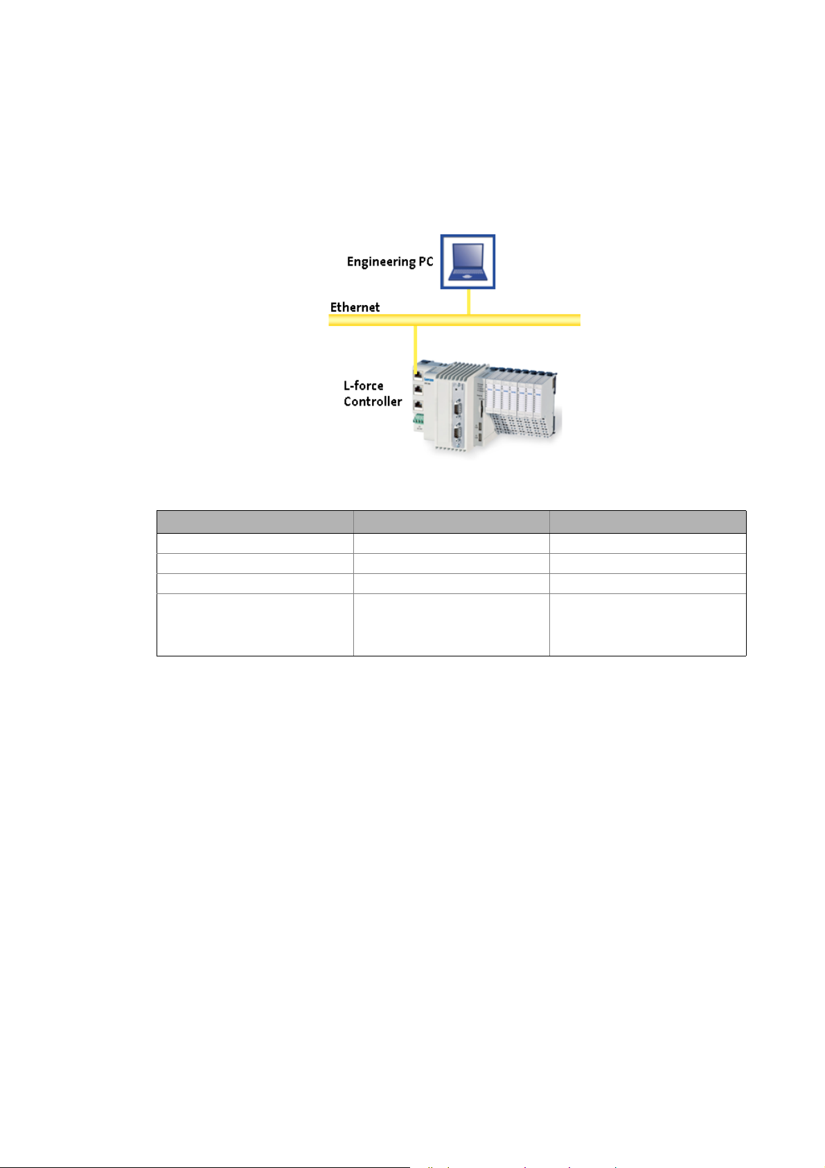
3.1 System requirements
[3-1] Illustration example: System structure with a Controller 3200 C
Hardware PC/notebook PLC (Logic) from firmware V3.1
Operating system Windows XP Windows CE
Required Lenze software »PLC Designer« V3.1 Logic
Further requirements Depending on the respective sample
3.2 What is the PLC Designer?
The »PLC Designer« is a Lenze engineering tool for programming the PLC of Lenze Controllers. The
Controller is the central control component of the Lenze Controller-based Automation system.
Product features
• Five different editors for the programming languages standardised in the IEC 61131-3 and a
very efficient CFC Editor are available. They can be used to create your own programs or to
address the functions of the Logic & Motion runtime software.
• By means of the integrated visualisation the processes are shown, in order to obtain all
important pieces of information at a glance during commissioning.
Engineering PC Controller
application:
• CAN or EtherCAT bus system
• CAN or EtherCAT node
14
Lenze · Commissioning of Lenze drives · 1.3 EN - 06/2014
Page 15

Preconditions
Where can I receive a full version of the PLC Designer?
_ _ _ _ _ _ _ _ _ _ _ _ _ _ _ _ _ _ _ _ _ _ _ _ _ _ _ _ _ _ _ _ _ _ _ _ _ _ _ _ _ _ _ _ _ _ _ _ _ _ _ _ _ _ _ _ _ _ _ _ _ _ _ _
3.3 Where can I receive a full version of the PLC Designer?
The »PLC Designer« is provided for download in the Lenze Application Knowledge Base (AKB) .
• The AKB is a product- and application-oriented collection of information provided by Lenze.
• Alternatively you can install the »PLC Designer« from the CD supplied with the Controller.
3.3.1 Installation
How to install the »PLC Designer«:
1. Select »PLC Designer« to save the full version as a packed ZIP file on your PC (Engineering
PC).
• Unpack the ZIP file PlcDesigner_V3.x.zip on your PC.
• The ZIP file contains an installation file.
or
Start the PLCDesigner_V3.x.exe installation file from the DC supplied with the Controller.
2. Start the EXE file and follow the installation instructions.
3. After the installation the »PLC Designer« can be started.
Further information and basics regarding the »PLC Designer« can be found in the
following documentation:
PLC Designer software manual
The manual is available on the CD supplied or on the Internet.
If the »PLC Designer« is already installed, carry out an update of the version available or install the
full version parallel to the version available.
Lenze · Commissioning of Lenze drives · 1.3 EN - 06/2014 15
Page 16

The Controller-based Automation system
_ _ _ _ _ _ _ _ _ _ _ _ _ _ _ _ _ _ _ _ _ _ _ _ _ _ _ _ _ _ _ _ _ _ _ _ _ _ _ _ _ _ _ _ _ _ _ _ _ _ _ _ _ _ _ _ _ _ _ _ _ _ _ _
4 The Controller-based Automation system
Central control technology becomes more and more important in the field of automation
technology. Due to their scaling options and various combinations of visualisation and control on
one device, Industrial PCs provide clear advantages for many applications.
The Controllers are available with the following software programs:
• Controllers as control system
• Controllers as visualisation system (depending on the model, an additional panel may be
required)
• Controllers as component, optionally with operating system, without any further software
The Controller-based Automation system enables the central control of Logic and Motion systems.
Further information on parameter setting and configuration of the individual bus
systems can be found in the following bus system-specific communication manuals:
16 Lenze · Commissioning of Lenze drives · 1.3 EN - 06/2014
Page 17

The Controller-based Automation system
_ _ _ _ _ _ _ _ _ _ _ _ _ _ _ _ _ _ _ _ _ _ _ _ _ _ _ _ _ _ _ _ _ _ _ _ _ _ _ _ _ _ _ _ _ _ _ _ _ _ _ _ _ _ _ _ _ _ _ _ _ _ _ _
Lenze supply specially matched system components:
• Controller as control and visualisation system
• The Controller is the central component in Controller-based Automation which uses the
runtime software to control the Logic and Motion functionalities.
• The controller communicates with the field devices via the fieldbus.
• Engineering tools for the Engineering PC
• The Engineering PC uses the Ethernet to communicate with the Controller.
• Use the various Engineering tools to configure and parameterise the system.
•Fieldbuses
•Field devices
Lenze · Commissioning of Lenze drives · 1.3 EN - 06/2014 17
Page 18

Commissioning
General system structure
_ _ _ _ _ _ _ _ _ _ _ _ _ _ _ _ _ _ _ _ _ _ _ _ _ _ _ _ _ _ _ _ _ _ _ _ _ _ _ _ _ _ _ _ _ _ _ _ _ _ _ _ _ _ _ _ _ _ _ _ _ _ _ _
5 Commissioning
This chapter describes the commissioning of a sample project by means of examples. The following
requirements have to be met, so that the respective sample project can be used.
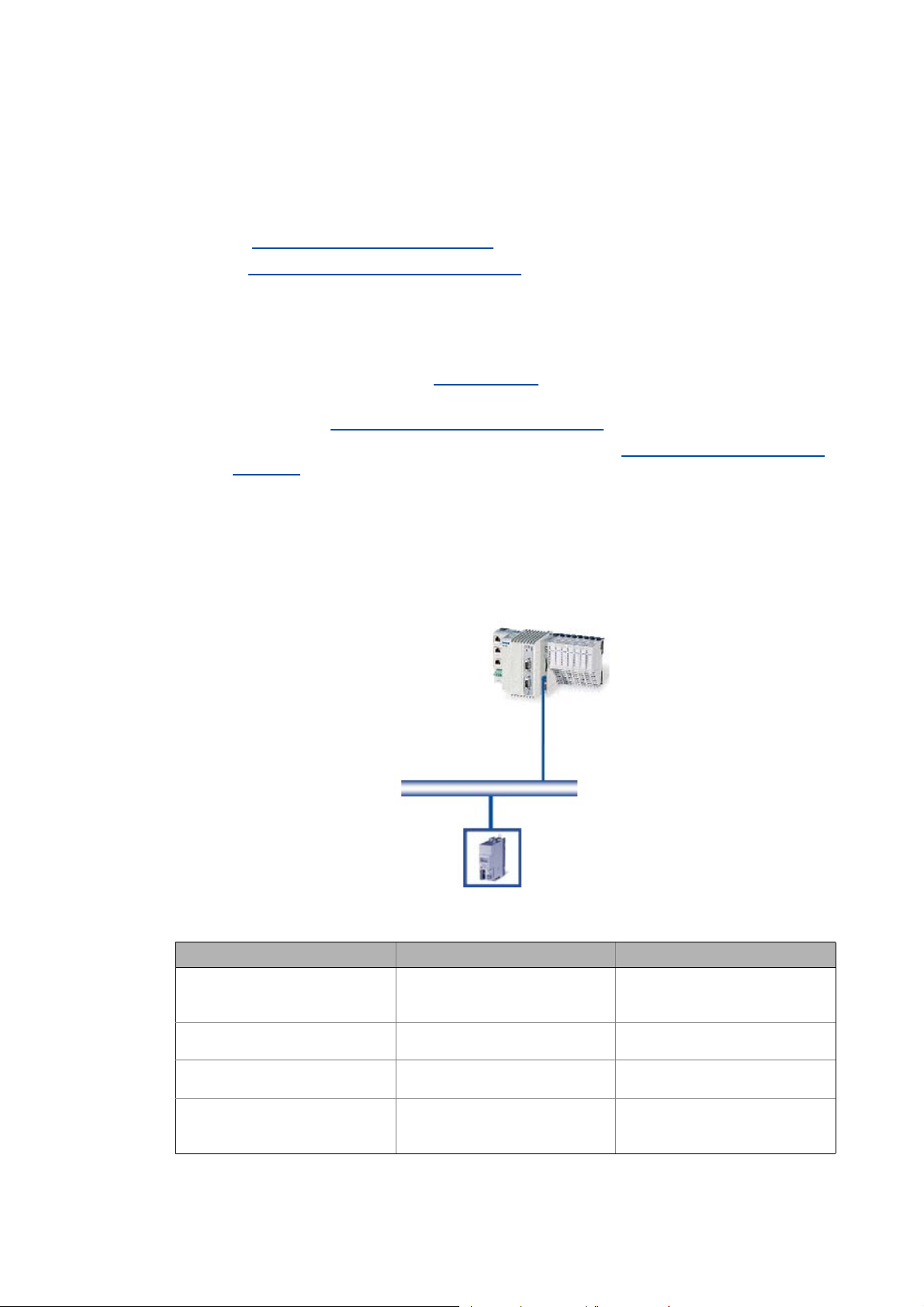
5.1 General system structure
The Lenze project examples are based on the following system structure.
• The Controller is the central control component of the system configuration.
• The sample projects are available for the following bus systems: CAN/EtherCAT.
[5-1] System structure with a Controller (Logic)
5.2 Wiring the hardware
Before you can work with the project, the hardware has to be connected to each other. The sample
projects are configured so that the motors rotate if a controller is used as fieldbus node.
• Connect the desired Controller with the fieldbus nodes.
• Connect the devices (controllers, motors) with the corresponding voltage supply
Further information on the electrical connections can be found in the documentation
supplied. Please read the mounting instructions supplied with the controller first before
you start working!
The mounting instructions include safety instructions which must be observed!
• Connect the components with a suitable fieldbus cable.
18
Lenze · Commissioning of Lenze drives · 1.3 EN - 06/2014
Page 19
Commissioning
Wiring the hardware
_ _ _ _ _ _ _ _ _ _ _ _ _ _ _ _ _ _ _ _ _ _ _ _ _ _ _ _ _ _ _ _ _ _ _ _ _ _ _ _ _ _ _ _ _ _ _ _ _ _ _ _ _ _ _ _ _ _ _ _ _ _ _ _
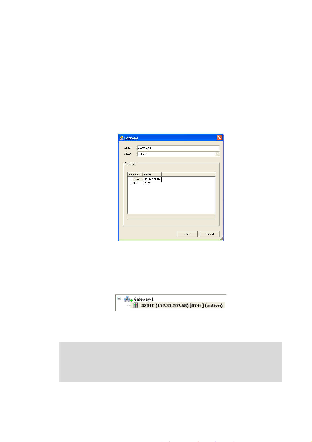
5.2.1 Setting up communication to the Controller
• Connect the Engineering PC with the controller via a network cable, as the »PLC Designer«
accesses the controller via Ethernet.
• Make the IP settings with the »PLC Designer«.
How to check the communication settings:
1. Go to the Device view and double-click the desired L-force Controller.
2. Make the desired settings on the Communication settings tab.
•Click the Add gateway button to insert a gateway.
• Enter the desired IP address of the L-force Controller.
[5-2] Example: Entering the IP address of the L-force Controller
3. Click OK to add the controller as gateway.
4. By double-clicking the desired channel (or clicking the Set active path button) set the
channel selected in the device tree below the gateway as active path for control.
• Thus, all communication actions directly refer to this channel.
• The currently active path is represented in bold in the list and "(active)" is attached:
5. A device represented in italics is set as momentarily active path but has not been found by
the last network scan.
Note!
• During initial commissioning, observe the following predefined IP addresses:
• Engineering PC: 192.168.5.100
• Controller: 192.168.5.99
Lenze · Commissioning of Lenze drives · 1.3 EN - 06/2014 19
Page 20

Commissioning
Wiring the hardware
_ _ _ _ _ _ _ _ _ _ _ _ _ _ _ _ _ _ _ _ _ _ _ _ _ _ _ _ _ _ _ _ _ _ _ _ _ _ _ _ _ _ _ _ _ _ _ _ _ _ _ _ _ _ _ _ _ _ _ _ _ _ _ _
Further information can be found in the following documentation:
• Controller - Parameter setting & configuration
5.2.2 Compiling the project data
To compile the project data, select the BuildCompile menu command or press the <F11> function
key.
• If errors have occurred during the compilation process, you can locate and eliminate them by
means of the »PLC Designer«error messages.
Then compile the project data again.
• If no errors have occurred during the compilation process, save the »PLC Designer«project in the
project folder.
5.2.3 Starting the sample project - Logging on to the control with the »PLC Designer«
First transmit the sample project to the PLC device and start it then. To log the »PLC Designer« on to
the control system, select the OnlineLogin menu command.
• For this, the PLC program must be error-free.
• With login, the PLC program is loaded in the control system.
5.2.4 Downloading and starting the PLC program
• If the PLC program has not been loaded yet onto the Controller, select the OnlineLoad menu
command.
• Select the OnlineRun menu command to start the PLC program.
Tip!
Install the PLC program as "boot project" in order to load it automatically after a device
is restarted.
How to install the project as boot project:
1. Open the Online menu in the menu bar
2. Select the Create boot project for L-force Controller command.
20
Lenze · Commissioning of Lenze drives · 1.3 EN - 06/2014
Page 21
Which Lenze application samples (AppSamples) exist?
Controller-based Automation: Application samples
_ _ _ _ _ _ _ _ _ _ _ _ _ _ _ _ _ _ _ _ _ _ _ _ _ _ _ _ _ _ _ _ _ _ _ _ _ _ _ _ _ _ _ _ _ _ _ _ _ _ _ _ _ _ _ _ _ _ _ _ _ _ _ _
6 Which Lenze application samples (AppSamples) exist?
The ready-configured sample projects are to facilitate the work with the Lenze products for
you. They include established system configurations representing typical application
cases. The objective is to obtain an executable Lenze automation system by using low
effort.
Depending on the application case, the sample projects can be optionally extended, and
thus they have to be adapted to the requirements in each case.
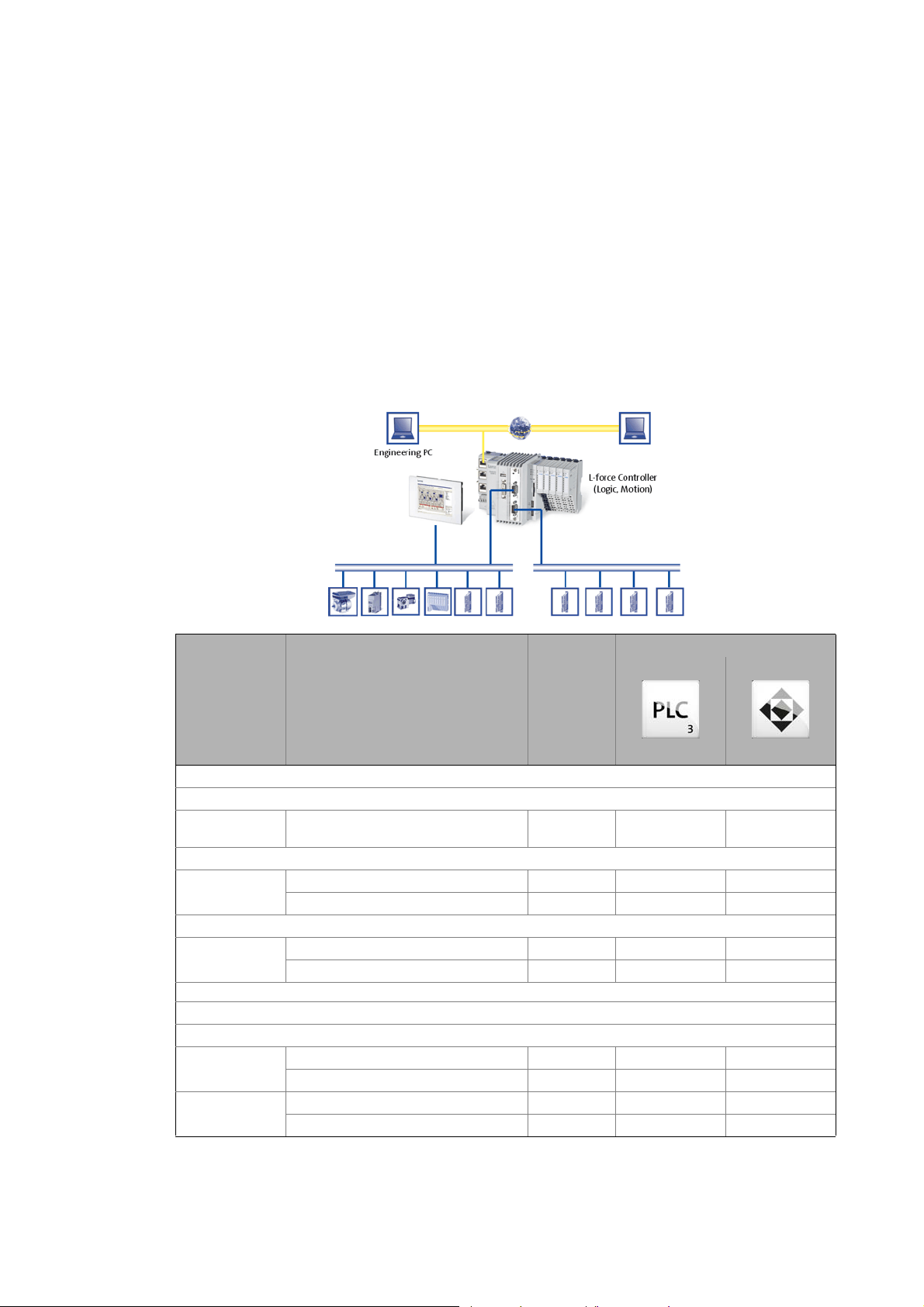
6.1 Controller-based Automation: Application samples
Product/device
application
Inverter Drives 8400
Baseline
Actuating drive
speed
Stateline
Actuating drive
speed
HighLine
Table
positioning
Servo Drives 9400
HighLine
Actuating drive
speed
Table
positioning
Project name Available for
bus system
LAS_40_INTF_Can_84BL_Speed_0100 CAN
LAS_40_INTF_Can_84SL_Speed_0200 CAN
LAS_40_INTF_ETC_84SL_Speed_0100 EtherCAT
LAS_40_INTF_Can_84HL_TabPos_0200 CAN
LAS_40_INTF_ETC_84HL_TabPos_0100 EtherCAT
LAS_40_INTF_Can_94HL_Speed_0200 CAN
LAS_40_INTF_ETC_94HL_Speed_0100 EtherCAT
LAS_40_INTF_Can_94HL_TabPos_0200 CAN
LAS_40_INTF_ETC_94HL_TabPos_0100 EtherCAT
Lenze Engineering tool
»PLC Designer«
V3.x
»Engineer«
V2.x
Lenze · Commissioning of Lenze drives · 1.3 EN - 06/2014 21
Page 22
Which Lenze application samples (AppSamples) exist?
Where do I find the sample projects?
_ _ _ _ _ _ _ _ _ _ _ _ _ _ _ _ _ _ _ _ _ _ _ _ _ _ _ _ _ _ _ _ _ _ _ _ _ _ _ _ _ _ _ _ _ _ _ _ _ _ _ _ _ _ _ _ _ _ _ _ _ _ _ _
6.2 Where do I find the sample projects?
After a successful »PLC Designer« installation, the sample projects can be found under:
(All) ProgramsLenzeAppSamples
6.3 How are the application samples called?
LAS_<Sortierschlüssel>_<Kategorie>_<Bussystem>_<Antriebsregler>_<Version>
Example: LAS_40_INTF_Can_84SL_Speed_xxx
Sort key/category
Sort key Category Description
40 INTF Application samples with interface function (interface connection) for
connecting Lenze controllers.
Differentiation of the bus systems
The sample projects are preconfigured for different bus systems.
Bus system Description
CAN CAN projects contain the "_Can" code in the file name.
EtherCAT EtherCAT projects contain the "_ETC" code in the file name.
6.4 Structure of the sample projects
Tip!
The »Engineer« sample projects are archived in ZIP format to allow you to send
them for instance by e-mail.
The »Engineer« supports project saving (FileSave archive) and project opening
(FileOpen archive) in ZIP format.
Each sample project consists of:
– Ready-made projects in the »Engineer«
– program code and visualisation in the »PLC Designer«. The following modes are
possible: automatic, manual (manual jog), service, homing (optional).
22
Lenze · Commissioning of Lenze drives · 1.3 EN - 06/2014
Page 23
Working with the sample projects
_ _ _ _ _ _ _ _ _ _ _ _ _ _ _ _ _ _ _ _ _ _ _ _ _ _ _ _ _ _ _ _ _ _ _ _ _ _ _ _ _ _ _ _ _ _ _ _ _ _ _ _ _ _ _ _ _ _ _ _ _ _ _ _
7 Working with the sample projects
The ready-configured sample projects are to facilitate the work with the Lenze components for you.
They include established system configurations representing typical application cases. The
objective is to obtain an executable Lenze automation system by using low effort.
Depending on the application case, the sample projects can be optionally extended, and thus they
have to be adapted to the requirements in each case.
Where do I find the sample projects?
After a successful installation of the Lenze sample projects they can be found under:
ProgramsLenzeAppSamples
The sample projects are preconfigured for different bus systems.
• CAN projects contain the "_Can" code in the file name
• EtherCAT projects contain the "_ETC" code in the file name
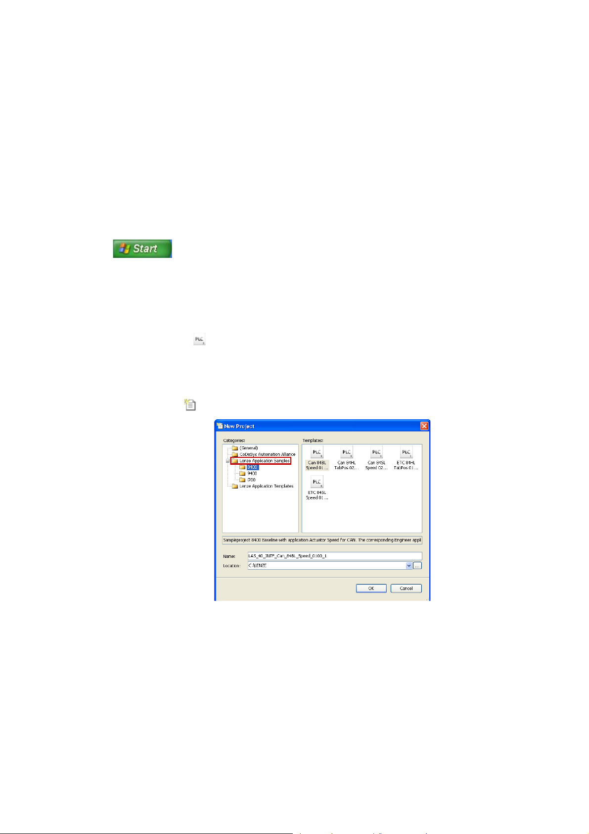
From »PLC Designer« V3.3 the Application Samples are available as predefined »PLC Designer«
projects (*.project, ) when a new project is created.
How to proceed:
1. Creating a new project:
• File New project
•Select category Lenze Application Samples.
• Open the desired Application Sample.
Tip!
The »Engineer« sample projects are archived in ZIP format to allow you to send them for
instance by e-mail.
The »Engineer« supports project saving (FileSave archive) and project opening
(FileOpen archive) in ZIP format.
Lenze · Commissioning of Lenze drives · 1.3 EN - 06/2014 23
Page 24

Working with the sample projects
_ _ _ _ _ _ _ _ _ _ _ _ _ _ _ _ _ _ _ _ _ _ _ _ _ _ _ _ _ _ _ _ _ _ _ _ _ _ _ _ _ _ _ _ _ _ _ _ _ _ _ _ _ _ _ _ _ _ _ _ _ _ _ _
Structure of the sample projects
• Each sample project consists of:
• ready-made project data in the »Engineer«
• program code and visualisation in the »PLC Designer«. The following modes are possible:
automatic, manual (manual jog), service, homing (optional).
24 Lenze · Commissioning of Lenze drives · 1.3 EN - 06/2014
Page 25
Working with the sample projects
Sample project with the "Actuator speed" application - Actuator Speed
_ _ _ _ _ _ _ _ _ _ _ _ _ _ _ _ _ _ _ _ _ _ _ _ _ _ _ _ _ _ _ _ _ _ _ _ _ _ _ _ _ _ _ _ _ _ _ _ _ _ _ _ _ _ _ _ _ _ _ _ _ _ _ _
7.1 Sample project with the "Actuator speed" application - Actuator Speed
Further information on the device-independent function libraries can be found in the
following section:
The L_LCB_LogicControlBasic library
The L_DCO_DriveCommunication library ( 100)
General procedure
( 113)
How to commission the controller:
1. Commission the controller. Commissioning
2. Load the desired project (depending on the desired bus system) to the controller using the
»Engineer«. Open the »Engineer« project & go online
3. Open the desired sample project in the »PLC Designer«. Program structure in the »PLC
Designer« ( 29)
4. Load the project to the Controller and go online.
( 26)
( 27)
7.1.1 Components to be used
[7-1] System configuration with L-force Controller CAN master (ID=0, connection to CAN1) and Lenze 8400 (CAN node ID=5)
Control supported field devices (bus system)
Hardware L-force Controller 8400 BaseLine (CAN)
8400 StateLine (CAN, EtherCAT)
9400 HighLine (CAN, EtherCAT)
Operating system From version Logic 3.1.x Firmware version is device-
Required Lenze software »PLC Designer« from version 3.1
»Engineer« from version 2.12
Further requirements • CAN master ID = 127
• Connection to interface CAN 1
• Logic CAN 500kB
dependent
-
• CAN node ID = 5
• EtherCAT station ID = 1001
Lenze · Commissioning of Lenze drives · 1.3 EN - 06/2014 25
Page 26

Working with the sample projects
Sample project with the "Actuator speed" application - Actuator Speed
_ _ _ _ _ _ _ _ _ _ _ _ _ _ _ _ _ _ _ _ _ _ _ _ _ _ _ _ _ _ _ _ _ _ _ _ _ _ _ _ _ _ _ _ _ _ _ _ _ _ _ _ _ _ _ _ _ _ _ _ _ _ _ _
7.1.2 Short overview of the functions
Mode Description
Automatic In the automatic mode a sequence runs over an infinite loop.
Selection:
•Travel for three seconds at speed1,
•then for five seconds at speed2,
• Start with speed1 again.
Manual In manual mode, the controller can be actuated manually by setting the
Service The service mode serves to adjust the controller.
7.1.3 Commissioning
individual control bits (Jog1, Jog2, QSP, ErrorReset...). Like this, the controller
can be controlled manually, e.g. for cleaning or changing the tools.
Selection:
• Travel positive for one second,
•Stop for one second,
• Travel negative for one second.
Read the mounting instructions accompanying the controller first before you start
working!
The mounting instructions contain safety instructions that must be observed!
1. Wire the power connections
• Use the mounting instructions supplied with the controller to correctly use the power
connections according to the requirements of your device.
2. Wire the control terminals
3. Connect USB diagnostic adapter.
4. Switch on the voltage supply of the controller.
• Connect mains voltage.
When the green LED "DRV-RDY" is blinking and the red LED "DRV-ERR" is off, the controller is ready
to start and you can continue with the commissioning.
26
Lenze · Commissioning of Lenze drives · 1.3 EN - 06/2014
Page 27
Working with the sample projects
Sample project with the "Actuator speed" application - Actuator Speed
_ _ _ _ _ _ _ _ _ _ _ _ _ _ _ _ _ _ _ _ _ _ _ _ _ _ _ _ _ _ _ _ _ _ _ _ _ _ _ _ _ _ _ _ _ _ _ _ _ _ _ _ _ _ _ _ _ _ _ _ _ _ _ _
7.1.4 Open the »Engineer« project & go online
Detailed information on the general handling of the »Engineer« can be found in the
online help for the »Engineer«, which you can call with [F1].
How to open the sample project in the »Engineer«:
1. Start »Engineer«.
2. Open the desired sample project using the FileOpen archive command.
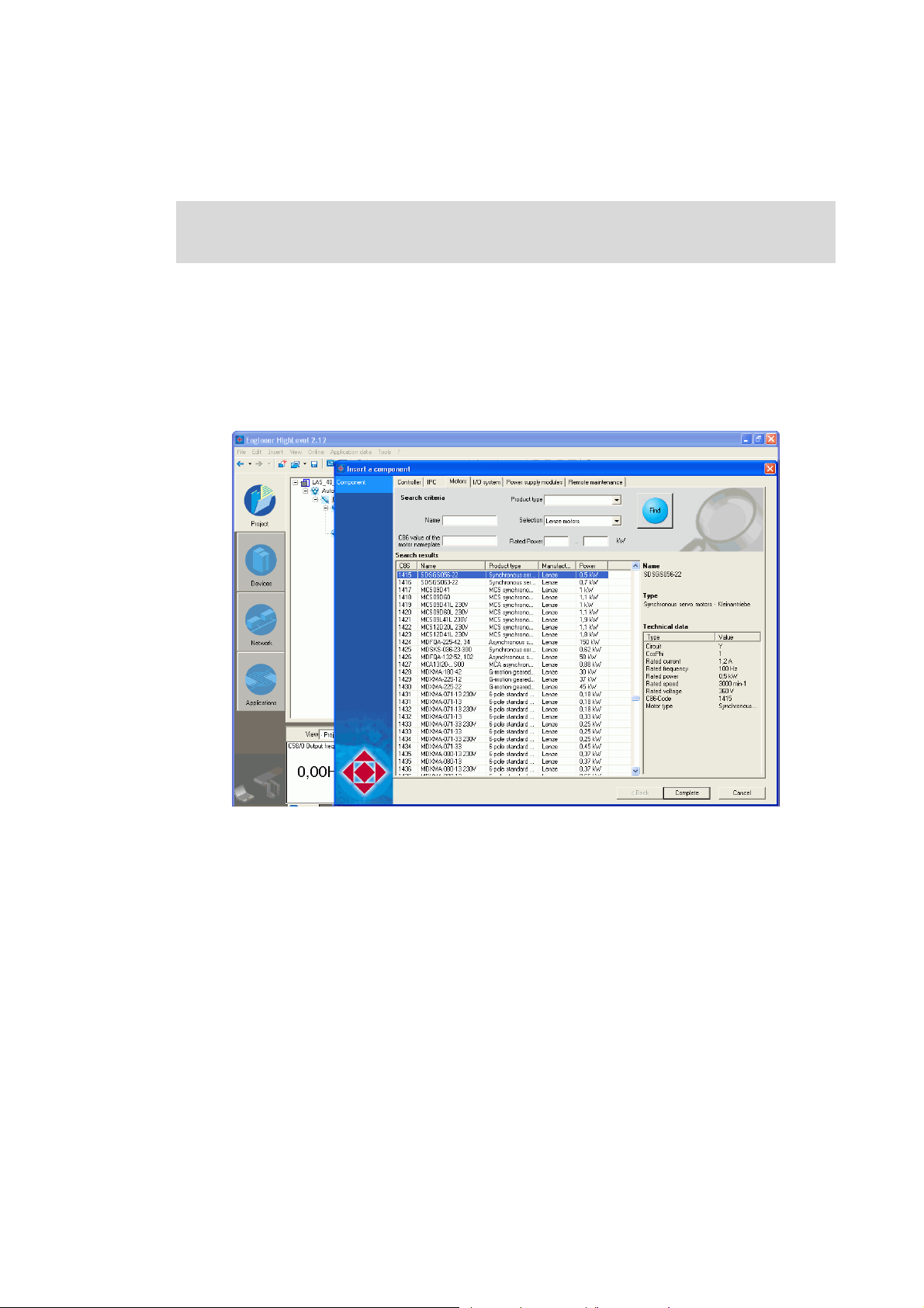
3. Insert the desired motor in the configuration:
• Highlight controller, select the desired motor with the command Insert a component on the
Motors tab
• By clicking Complete, insert the selection in the »Engineer« project.
Lenze · Commissioning of Lenze drives · 1.3 EN - 06/2014 27
Page 28
Working with the sample projects
Sample project with the "Actuator speed" application - Actuator Speed
_ _ _ _ _ _ _ _ _ _ _ _ _ _ _ _ _ _ _ _ _ _ _ _ _ _ _ _ _ _ _ _ _ _ _ _ _ _ _ _ _ _ _ _ _ _ _ _ _ _ _ _ _ _ _ _ _ _ _ _ _ _ _ _
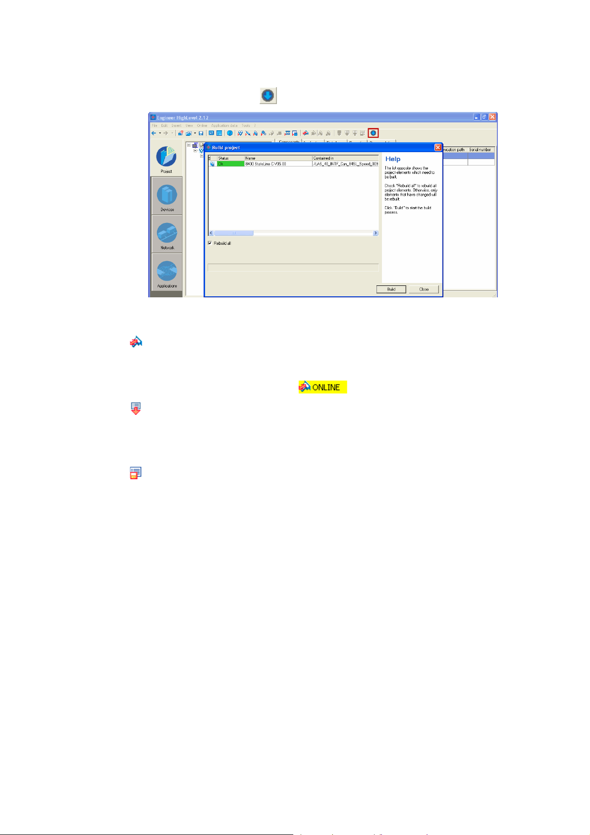
4. Update the project by clicking :
• Select the option Rebuild all
•Click the Build button to update the project.
5. Going online
• After a connection to the controller has been established successfully, the following status is
displayed in the Status line:
6. Download parameter set
• This command has the effect that the application and the parameter settings of the
»Engineer« project overwrite the parameter settings in the controller.
7. Optional: Adapt desired communication settings (for instance network address, baud rate).
8. Store parameter set
9. Mains switching to accept the communication settings to the device.
28
Lenze · Commissioning of Lenze drives · 1.3 EN - 06/2014
Page 29

Working with the sample projects
Sample project with the "Actuator speed" application - Actuator Speed
_ _ _ _ _ _ _ _ _ _ _ _ _ _ _ _ _ _ _ _ _ _ _ _ _ _ _ _ _ _ _ _ _ _ _ _ _ _ _ _ _ _ _ _ _ _ _ _ _ _ _ _ _ _ _ _ _ _ _ _ _ _ _ _
7.1.5 Program structure in the »PLC Designer«
How to proceed:
1. Open the desired sample project (CAN or EtherCAT) in the »PLC Designer«.
2. Load the project to the Controller and Go online.
7.1.5.1 Control configuration
CAN
• The CAN master (ID = 127) is the control section of the system configuration
• The controller (CAN node ID = 5) is attached below the CAN master.
• Below the controller, the axis data are available in the form of an additional node.
• One PDO for CAN-Input and one PDO for CAN-Output is used, respectively.
• The transmission mode is sync-controlled (10 ms)
You can find further details on the extension of the control configuration with CAN and EtherCAT in
the following section: Extending sample projects - adding devices
( 51)
EtherCAT
• The EtherCAT master is the control section of the system configuration
• The controller (station ID = 1001) is attached below the EtherCAT master.
• Below the controller, the axis data are available in the form of an additional node.
Lenze · Commissioning of Lenze drives · 1.3 EN - 06/2014 29
Page 30
Working with the sample projects
Sample project with the "Actuator speed" application - Actuator Speed
_ _ _ _ _ _ _ _ _ _ _ _ _ _ _ _ _ _ _ _ _ _ _ _ _ _ _ _ _ _ _ _ _ _ _ _ _ _ _ _ _ _ _ _ _ _ _ _ _ _ _ _ _ _ _ _ _ _ _ _ _ _ _ _
7.1.5.2 Program organisation units
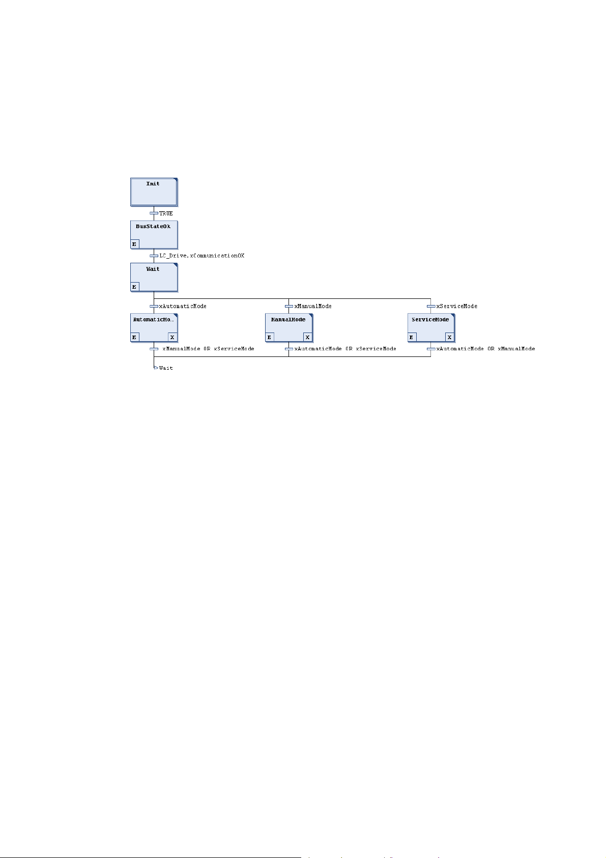
"Main" program
• The "Main (PRG)" program is the basic program for processing the program sequences:
initialisation of the controller and selection of the different modes.
[7-2] Main (PRG)
30
Lenze · Commissioning of Lenze drives · 1.3 EN - 06/2014
Page 31

Working with the sample projects
Sample project with the "Actuator speed" application - Actuator Speed
_ _ _ _ _ _ _ _ _ _ _ _ _ _ _ _ _ _ _ _ _ _ _ _ _ _ _ _ _ _ _ _ _ _ _ _ _ _ _ _ _ _ _ _ _ _ _ _ _ _ _ _ _ _ _ _ _ _ _ _ _ _ _ _
"Drive" program
• The "Drive (PRG)" program actuates the controller using the function block
L_LCB_ActuatorSpeed.
• The connection of the AXIS_REF-instance(LC_Drive) provides a connection to the control
configuration.
Lenze · Commissioning of Lenze drives · 1.3 EN - 06/2014 31
Page 32

Working with the sample projects
Sample project with the "Actuator speed" application - Actuator Speed
_ _ _ _ _ _ _ _ _ _ _ _ _ _ _ _ _ _ _ _ _ _ _ _ _ _ _ _ _ _ _ _ _ _ _ _ _ _ _ _ _ _ _ _ _ _ _ _ _ _ _ _ _ _ _ _ _ _ _ _ _ _ _ _
"PLC_PRG" program
• The "PLC_PRG (PRG)" program contains all program calls.
32
Lenze · Commissioning of Lenze drives · 1.3 EN - 06/2014
Page 33

Working with the sample projects
Sample project with the "Actuator speed" application - Actuator Speed
_ _ _ _ _ _ _ _ _ _ _ _ _ _ _ _ _ _ _ _ _ _ _ _ _ _ _ _ _ _ _ _ _ _ _ _ _ _ _ _ _ _ _ _ _ _ _ _ _ _ _ _ _ _ _ _ _ _ _ _ _ _ _ _
7.1.6 Operation via the visualisations in the »PLC Designer«
7.1.6.1 Information/start page
[7-3] Visualisation start page of the sample project Lenze 8400 HighLine - Actuator Speed
Select mode Information/start page Status
Parameter
selection
• Via the buttons in area , the mode (automatic, manual, service) can be selected.
•In area , SDO services (read/write parameters) for the controller can be selected.
• The button in area refers to the start page which displays the version identifier of the project
and the libraries in area .
• Dialog box shows the status of the machine.
• Control field shows the bus communication status.
Version identifier Status
Note!
If a bus communication error occurs, the control and drive controller are to be restarted,
since the sample application does not support an automatic reset of bus
communication.
• Control field Error indicates the error message status.
• Error in the application
• Error in the controller
•The Error Reset button resets the error messages.
Lenze · Commissioning of Lenze drives · 1.3 EN - 06/2014 33
Page 34

Working with the sample projects
Sample project with the "Actuator speed" application - Actuator Speed
_ _ _ _ _ _ _ _ _ _ _ _ _ _ _ _ _ _ _ _ _ _ _ _ _ _ _ _ _ _ _ _ _ _ _ _ _ _ _ _ _ _ _ _ _ _ _ _ _ _ _ _ _ _ _ _ _ _ _ _ _ _ _ _
7.1.6.2 Automatic mode
Select mode Stop button Actual speed Status
Start button Status Status
• Button selects the automatic mode.
• Button starts the motion profile.
• Button inhibits the motion profile.
•Display field indicates the status of the mode.
•Display field shows the current speed (Speed Value variable).
• Dialog box indicates the machine status.
• Control field shows the bus communication status.
Note!
If a bus communication error occurs, the control and drive controller are to be restarted,
since the sample application does not support an automatic reset of bus
communication.
• Control field Error indicates the error message status.
• Error in the application
• Error in the controller
•The Error Reset button resets the error messages.
7.1.6.3 Manual mode ("Manual jog")
The controller can be actuated manually via the visualisation of the L_LCB_ActuatorSpeed block.
34
Lenze · Commissioning of Lenze drives · 1.3 EN - 06/2014
Page 35

Working with the sample projects
Sample project with the "Actuator speed" application - Actuator Speed
_ _ _ _ _ _ _ _ _ _ _ _ _ _ _ _ _ _ _ _ _ _ _ _ _ _ _ _ _ _ _ _ _ _ _ _ _ _ _ _ _ _ _ _ _ _ _ _ _ _ _ _ _ _ _ _ _ _ _ _ _ _ _ _
Select mode Control panel Activate control via visualisation
• Button selects the manual (manual jog) mode.
• In the control and status panel the FB for actuating the controller is visualised.
Note: Activate button to be able to operate the controller via the visualisation.
• Enable the controller via the xDriveEnable FB input to be able to define setpoints manually.
Note: Click the xDriveSetQsp button to activate quick stop.
For more information on the FB, please see the following section:L_LCB_ActuatorSpeed
( 120)
Lenze · Commissioning of Lenze drives · 1.3 EN - 06/2014 35
Page 36

Working with the sample projects
Sample project with the "Actuator speed" application - Actuator Speed
_ _ _ _ _ _ _ _ _ _ _ _ _ _ _ _ _ _ _ _ _ _ _ _ _ _ _ _ _ _ _ _ _ _ _ _ _ _ _ _ _ _ _ _ _ _ _ _ _ _ _ _ _ _ _ _ _ _ _ _ _ _ _ _
7.1.6.4 Service mode
Select mode Stop button Status of the service mode
Start button Activate clockwise
rotation (CW)
• Button selects the service mode.
• Button starts the motion profile.
• Button inhibits the motion profile.
• Button sets clockwise rotation (clockwise rotating direction of the motor).
•Display field indicates the status of the mode.
•Display field indicates the current speed (variable Actual Value).
•Display field shows the currently set speed setpoint.
• Possible setpoint data for the motion profile: 0 ... 100%.
• Dialog box shows the status of the machine.
• Control field shows the bus communication status.
Actual speed Setpoint speed
Note!
If a bus communication error occurs, the control and drive controller are to be restarted,
since the sample application does not support an automatic reset of bus
communication.
36
• Control field Error indicates the error message status.
• Error in the application
• Error in the controller
•The Error Reset button resets the error messages.
Lenze · Commissioning of Lenze drives · 1.3 EN - 06/2014
Page 37

Working with the sample projects
Sample project with the "Actuator speed" application - Actuator Speed
_ _ _ _ _ _ _ _ _ _ _ _ _ _ _ _ _ _ _ _ _ _ _ _ _ _ _ _ _ _ _ _ _ _ _ _ _ _ _ _ _ _ _ _ _ _ _ _ _ _ _ _ _ _ _ _ _ _ _ _ _ _ _ _
7.1.6.5 Parameter
The Parameter button selects the visualisation of the parameter FBs.
• The mode selected last remains active.
• You can use the FBs to...
• read individual parameters
• write individual parameters
Read parameters Write parameters
•Area shows the FB for reading parameters.
For more information on the FB, please see the following section:
L_DCO_ReadDriveParameter
•Area shows the FB for writing a parameter table.
Further information on the FB can be found in the following section:
L_DCO_WriteDriveParameter
( 105)
( 110)
Lenze · Commissioning of Lenze drives · 1.3 EN - 06/2014 37
Page 38

Working with the sample projects
Sample project with "Table positioning" application - TablePositioning
_ _ _ _ _ _ _ _ _ _ _ _ _ _ _ _ _ _ _ _ _ _ _ _ _ _ _ _ _ _ _ _ _ _ _ _ _ _ _ _ _ _ _ _ _ _ _ _ _ _ _ _ _ _ _ _ _ _ _ _ _ _ _ _
7.2 Sample project with "Table positioning" application - TablePositioning
Further information on the function libraries used in this project can be found in the
following section:
The L_LCB_LogicControlBasic library
The L_DCO_DriveCommunication library ( 100)
L_LCB_TablePositioning ( 124)
General procedure
How to commission the controller:
1. Commission the controller. Commissioning
2. Load the desired project (depending on the desired bus system) to the controller using the
»Engineer. Open the »Engineer« project & go online
3. Open the desired sample project in the »PLC Designer« Program structure in the »PLC
Designer« ( 42)
4. Load the project to the Controller and go online.
7.2.1 Components to be used
( 39)
( 40)
[7-4] System configuration with Controller (ID=0, connection to CAN1) and 8400 HighLine (CAN node ID=5)
Control supported field devices (bus system)
Hardware L-force Controller 8400 HighLine CAN (CAN, EtherCAT)
Operating system From version Logic 3.1.x Firmware version is device-
Required Lenze software »PLC Designer« from version 3
»Engineer« from version 2.12
Further requirements • CAN master ID = 127
• Connection to interface CAN 1
• Logic CAN 500kB
38
Lenze · Commissioning of Lenze drives · 1.3 EN - 06/2014
9400 HighLine CAN (CAN, EtherCAT)
dependent
-
• CAN node ID = 5
• EtherCAT station ID = 1001
Page 39

Working with the sample projects
Sample project with "Table positioning" application - TablePositioning
_ _ _ _ _ _ _ _ _ _ _ _ _ _ _ _ _ _ _ _ _ _ _ _ _ _ _ _ _ _ _ _ _ _ _ _ _ _ _ _ _ _ _ _ _ _ _ _ _ _ _ _ _ _ _ _ _ _ _ _ _ _ _ _
7.2.2 Short overview of the functions
Mode Description
Automatic In the automatic mode a sequence runs over an infinite loop.
Selection:
When the drive has been referenced...
1.travel to position 1,
2.travel to position 2,
3.restart at (1.).
Manual In manual mode, the controller can be manually actuated by setting the
Service The service mode serves to adjust the controller.
Homing In homing mode, the drive is referenced.
single control bits (xManualPos, xManualNeg, xDriveSetQsp, xResetError).
Like this, the controller can be controlled manually, e.g. for cleaning or
changing the tools.
Selection:
• Travel positive for one second,
•Stop for one second,
• Travel negative for one second.
• Either the home position is set directly, or a homing is started.
7.2.3 Commissioning
Read the mounting instructions accompanying the controller first before you start
working!
The mounting instructions contain safety instructions that must be observed!
1. Wire the power connections
• Use the mounting instructions supplied with the controller to correctly use the power
connections according to the requirements of your device.
2. Wire the control terminals
3. Connect USB diagnostic adapter.
4. Switch on the voltage supply of the controller.
• Connect mains voltage.
When the green LED "DRV-RDY" is blinking and the red LED "DRV-ERR" is off, the controller is ready
to start and you can continue with the commissioning.
Lenze · Commissioning of Lenze drives · 1.3 EN - 06/2014 39
Page 40

Working with the sample projects
Sample project with "Table positioning" application - TablePositioning
_ _ _ _ _ _ _ _ _ _ _ _ _ _ _ _ _ _ _ _ _ _ _ _ _ _ _ _ _ _ _ _ _ _ _ _ _ _ _ _ _ _ _ _ _ _ _ _ _ _ _ _ _ _ _ _ _ _ _ _ _ _ _ _
7.2.4 Open the »Engineer« project & go online
Detailed information on the general handling of the »Engineer« can be found in the
online help for the »Engineer«, which you can call with [F1].
How to open the sample project in the »Engineer«:
1. Start »Engineer«.
2. Open the desired project (CAN or EtherCAT) using the FileOpen archive command.
3. Insert the desired motor in the configuration:
• Highlight controller, select the desired motor with the command Insert a component on the
Motors tab
• By clicking Complete, insert the selection in the »Engineer« project.
40
Lenze · Commissioning of Lenze drives · 1.3 EN - 06/2014
Page 41

Working with the sample projects
Sample project with "Table positioning" application - TablePositioning
_ _ _ _ _ _ _ _ _ _ _ _ _ _ _ _ _ _ _ _ _ _ _ _ _ _ _ _ _ _ _ _ _ _ _ _ _ _ _ _ _ _ _ _ _ _ _ _ _ _ _ _ _ _ _ _ _ _ _ _ _ _ _ _
4. Update the project by clicking :
• Select the option Rebuild all
•Click the Build button to update the project.
5. Going online
• After a connection to the controller has been established successfully, the following status is
displayed in the Status line:
6. Download parameter set
• This command has the effect that the application and the parameter settings of the
»Engineer« project overwrite the parameter settings in the controller.
7. Optional: Adapt desired communication settings (for instance network address, baud rate).
8. Store parameter set
9. Mains switching to accept the communication settings to the device.
Lenze · Commissioning of Lenze drives · 1.3 EN - 06/2014 41
Page 42

Working with the sample projects
Sample project with "Table positioning" application - TablePositioning
_ _ _ _ _ _ _ _ _ _ _ _ _ _ _ _ _ _ _ _ _ _ _ _ _ _ _ _ _ _ _ _ _ _ _ _ _ _ _ _ _ _ _ _ _ _ _ _ _ _ _ _ _ _ _ _ _ _ _ _ _ _ _ _
7.2.5 Program structure in the »PLC Designer«
How to proceed:
1. Open the desired sample project (CAN or EtherCAT) in the »PLC Designer«.
2. Load the project to the Controller and Go online.
7.2.5.1 Control configuration
CAN
• The CAN master (ID = 127) is the control section of the system configuration
• The controller (CAN node ID = 5) is attached below the CAN master.
• Below the controller, the axis data are available in the form of an additional node.
• Two PDOs for CAN-Input and CAN-Output are used, respectively.
• The transmission mode is sync-controlled (10 ms).
You can find further details on the extension of the control configuration with CAN and EtherCAT in
the following section: Extending sample projects - adding devices
( 51)
EtherCAT
• The EtherCAT master is the control section of the system configuration
• The controller (station ID = 1001) is attached below the EtherCAT master.
• Below the controller, the axis data are available in the form of an additional node.
7.2.5.2 Program organisation units
"Main" program
• The "Main (PRG)" program is the basic program for processing the program sequences:
initialisation of the controller and selection of the different modes.
[7-5] Example: Main (PRG)
42
Lenze · Commissioning of Lenze drives · 1.3 EN - 06/2014
Page 43

Working with the sample projects
Sample project with "Table positioning" application - TablePositioning
_ _ _ _ _ _ _ _ _ _ _ _ _ _ _ _ _ _ _ _ _ _ _ _ _ _ _ _ _ _ _ _ _ _ _ _ _ _ _ _ _ _ _ _ _ _ _ _ _ _ _ _ _ _ _ _ _ _ _ _ _ _ _ _
"Drive" program
• The "DRIVE (PRG)" program actuates the controller using the function block
L_LCB_TablePositioning an.
• The machine constants are provided in a conditioned manner by means of the
L_LCB_SetAxisData block.
• The connection of the AXIS_REF-instance(LC_Drive) provides a connection to the control
configuration.
Lenze · Commissioning of Lenze drives · 1.3 EN - 06/2014 43
Page 44

Working with the sample projects
Sample project with "Table positioning" application - TablePositioning
_ _ _ _ _ _ _ _ _ _ _ _ _ _ _ _ _ _ _ _ _ _ _ _ _ _ _ _ _ _ _ _ _ _ _ _ _ _ _ _ _ _ _ _ _ _ _ _ _ _ _ _ _ _ _ _ _ _ _ _ _ _ _ _
"PLC_PRG" program
• The "PLC_PRG (PRG)" program contains all program calls.
44
Lenze · Commissioning of Lenze drives · 1.3 EN - 06/2014
Page 45

Working with the sample projects
Sample project with "Table positioning" application - TablePositioning
_ _ _ _ _ _ _ _ _ _ _ _ _ _ _ _ _ _ _ _ _ _ _ _ _ _ _ _ _ _ _ _ _ _ _ _ _ _ _ _ _ _ _ _ _ _ _ _ _ _ _ _ _ _ _ _ _ _ _ _ _ _ _ _
7.2.6 Operation via the visualisations in the »PLC Designer«
7.2.6.1 Information/start page
[7-6] Example: Visualisation start page of the sample project Lenze 8400 HighLine - TablePositioning
Select mode Manufacturer information Status
Parameter
selection
• Via the buttons in area , the mode (automatic, manual, service, homing) can be selected.
•In area , SDO services (read/write parameters) for the controller can be selected.
• The button in area refers to the start page which displays the version identifier of the project
and the libraries in area .
• Dialog box shows the status of the machine.
• Control field shows the bus communication status.
Information/home page Status
Note!
If a bus communication error occurs, the control and drive controller are to be restarted,
since the sample application does not support an automatic reset of bus
communication.
• Control field Error indicates the error message status.
• Error in the application
• Error in the controller
•The Error Reset button resets the error messages.
Lenze · Commissioning of Lenze drives · 1.3 EN - 06/2014 45
Page 46

Working with the sample projects
Sample project with "Table positioning" application - TablePositioning
_ _ _ _ _ _ _ _ _ _ _ _ _ _ _ _ _ _ _ _ _ _ _ _ _ _ _ _ _ _ _ _ _ _ _ _ _ _ _ _ _ _ _ _ _ _ _ _ _ _ _ _ _ _ _ _ _ _ _ _ _ _ _ _
7.2.6.2 Automatic mode
Select mode Stop button Current profile
Start button Mode status Set position
• Button selects the automatic mode.
• Button starts the motion profile.
• Button inhibits the motion profile.
•Display field indicates the status of the mode.
•Display field indicates the current profile number.
•Display field indicates the set position.
number
46
Lenze · Commissioning of Lenze drives · 1.3 EN - 06/2014
Page 47

Working with the sample projects
Sample project with "Table positioning" application - TablePositioning
_ _ _ _ _ _ _ _ _ _ _ _ _ _ _ _ _ _ _ _ _ _ _ _ _ _ _ _ _ _ _ _ _ _ _ _ _ _ _ _ _ _ _ _ _ _ _ _ _ _ _ _ _ _ _ _ _ _ _ _ _ _ _ _
7.2.6.3 Manual mode ("Manual jog")
The controller can be actuated manually via the visualisation of the L_LCB_TablePositioning block.
Select mode Control/status panel Activate control via visualisation
• Button selects the manual (manual jog) mode.
• The control and status panel contains the FB for actuating the controller.
• The controller can be actuated manually via the visualisation of the L_LCB_TablePositioning
block.
Note: Activate button to be able to operate the controller via the visualisation.
• Enable the controller via the xDriveEnable FB input to be able to define setpoints manually.
Note: Click the xDriveSetQsp button to activate quick stop.
Further information on the FB can be found in the following section:
L_LCB_TablePositioning
•Area visualises the FB for reading out the errors from the controller.
Further information on the FB can be found in the following section:
L_DCO_ReadDriveParameter
( 120)
( 105)
Lenze · Commissioning of Lenze drives · 1.3 EN - 06/2014 47
Page 48

Working with the sample projects
Sample project with "Table positioning" application - TablePositioning
_ _ _ _ _ _ _ _ _ _ _ _ _ _ _ _ _ _ _ _ _ _ _ _ _ _ _ _ _ _ _ _ _ _ _ _ _ _ _ _ _ _ _ _ _ _ _ _ _ _ _ _ _ _ _ _ _ _ _ _ _ _ _ _
7.2.6.4 Service mode
Select mode Stop button Status of the service mode
Start button Activate clockwise
rotation
• Button selects the service mode.
• Button starts the motion profile.
• Button inhibits the motion profile.
• Button selects clockwise rotation (clockwise rotating direction of the motor).
•Display field indicates the status of the mode.
•Display field indicates the current speed (variable Speed Value).
• Dialog box shows the status of the machine.
• Control field shows the bus communication status.
Actual speed
Note!
If a bus communication error occurs, the control and drive controller are to be restarted,
since the sample application does not support an automatic reset of bus
communication.
• Control field Error indicates the error message status.
• Error in the application
• Error in the controller
•The Error Reset button resets the error messages.
48
Lenze · Commissioning of Lenze drives · 1.3 EN - 06/2014
Page 49

Working with the sample projects
Sample project with "Table positioning" application - TablePositioning
_ _ _ _ _ _ _ _ _ _ _ _ _ _ _ _ _ _ _ _ _ _ _ _ _ _ _ _ _ _ _ _ _ _ _ _ _ _ _ _ _ _ _ _ _ _ _ _ _ _ _ _ _ _ _ _ _ _ _ _ _ _ _ _
7.2.6.5 Homing mode
Select mode Stop button Status of the service mode
Start button Activate clockwise
rotation
• Button selects the homing mode.
• The active standard setting in the controller is homing mode 12 (travel to negative limit
switch / digital input 3)
• Button starts the homing.
• Button stops homing.
• Button sets the home position.
• Button resets the home position.
• Set reference / Pos Act = 0 unit
• Dialog box shows the homing status.
Actual speed
Lenze · Commissioning of Lenze drives · 1.3 EN - 06/2014 49
Page 50

Working with the sample projects
Sample project with "Table positioning" application - TablePositioning
_ _ _ _ _ _ _ _ _ _ _ _ _ _ _ _ _ _ _ _ _ _ _ _ _ _ _ _ _ _ _ _ _ _ _ _ _ _ _ _ _ _ _ _ _ _ _ _ _ _ _ _ _ _ _ _ _ _ _ _ _ _ _ _
7.2.6.6 Parameter
The Parameter button selects the visualisation of the parameter FBs.
• The mode selected last remains active.
• You can use the FBs to...
• read individual parameters (L_DCO_ReadDriveParameter)
• write individual parameters (L_DCO_WriteDriveParameter)
Read parameters Write parameters
•Area shows the FB for reading parameters. L_DCO_ReadDriveParameter
•Area shows the FB for writing a parameter table. L_DCO_WriteDriveParameter ( 110)
( 105)
50
Lenze · Commissioning of Lenze drives · 1.3 EN - 06/2014
Page 51

Extending sample projects - adding devices
Creating a control configuration - EtherCAT bus system
_ _ _ _ _ _ _ _ _ _ _ _ _ _ _ _ _ _ _ _ _ _ _ _ _ _ _ _ _ _ _ _ _ _ _ _ _ _ _ _ _ _ _ _ _ _ _ _ _ _ _ _ _ _ _ _ _ _ _ _ _ _ _ _
8 Extending sample projects - adding devices
This chapter informs you on how to extend the control configuration manually.
• Lenze provide ready-made sample projects in which the control configuration has already been
created. More information can be found in the following section: Working with the sample
projects ( 23)
• Proceed as described below to extend an existing sample project individually. Please note that
the communication settings have to be adapted for each individual node.
8.1 Creating a control configuration - EtherCAT bus system
Note!
Before creating an EtherCAT configuration in »PLC Designer«, ensure that the following
conditions have been met:
• The sequence of EtherCAT slaves in the device tree must correspond to the physical
arrangement of the EtherCAT topology.
• In order that the system works properly, end terminals must not be used when setting
up the system configuration in the device tree.
• Select the cycle times according to the technical data, from 1 ... 10 ms.
How to create the control configuration in the »PLC Designer«:
1. Open the context menu of the target system and execute the command Append device
in order to extend the control configuration with "EtherCAT Master".
Lenze · Commissioning of Lenze drives · 1.3 EN - 06/2014 51
Page 52

Extending sample projects - adding devices
Creating a control configuration - EtherCAT bus system
_ _ _ _ _ _ _ _ _ _ _ _ _ _ _ _ _ _ _ _ _ _ _ _ _ _ _ _ _ _ _ _ _ _ _ _ _ _ _ _ _ _ _ _ _ _ _ _ _ _ _ _ _ _ _ _ _ _ _ _ _ _ _ _
2. Add an EtherCAT slave below the EtherCAT master.
• Manually using the Add Device command in the context menu of the CANopen
master
Select a field device from the selection list. You can only select devices the CANopen
device description files of which have been imported in the »PLC Designer«.
The »PLC Designer« provides a "fieldbus scan" during which the devices connected to the
fieldbus are automatically detected.
• More information can be found in the section "Lenze specificationsEtherCAT control
technology" of the online help for the »PLC Designer« and in the EtherCAT
communication manual (KHB)- Commissioning & configuration.
Repeat the Add Device command until all slaves connected to the fieldbus are included
in the control configuration.
52
Lenze · Commissioning of Lenze drives · 1.3 EN - 06/2014
Page 53

Extending sample projects - adding devices
Create control configuration - bus system CAN
_ _ _ _ _ _ _ _ _ _ _ _ _ _ _ _ _ _ _ _ _ _ _ _ _ _ _ _ _ _ _ _ _ _ _ _ _ _ _ _ _ _ _ _ _ _ _ _ _ _ _ _ _ _ _ _ _ _ _ _ _ _ _ _
3. Give the inserted slaves suitable names (e.g. "Drive_vertical").
The names must …
• only contain the characters "A ... Z", "a ... z", "0 ... 9" or "_";
• must not begin with a digit.
You can enter a name by clicking the element.
Example:
• Below the selected slave, the axis data are available in the form of an additional node.
L_LCB_AXIS_REF
Connect a function block to the LC_Drive instance to establish a connection to the slave.
Transmitted process data are written automatically to the axis data. Hence, no manual
assignment of the process data to the application is required. Overview: The libraries for
controlling the inverters ( 82)
( 115)
Note!
During runtime the parameters can only be changed by means of the corresponding
function blocks. Afterwards, a manual adjustment with the controller is required!
8.2 Create control configuration - bus system CAN
Note!
An L-force Controller in the CANopen network must be configured in the »PLC Designer«
since the complete configuration is written to the connected slaves when the Controller
is started. During this process, previous settings in slaves are overwritten.
• In order to be able to link the process data
manually (instead of the automatic link to
the L_LCB_Axis_REF instance), the Manual
I/O mapping option has to be activated.
How to create the control configuration in the »PLC Designer«:
1. Go to the context menu of the target system and use the Add Device command to
extend the control configuration with "CANbus".
Lenze · Commissioning of Lenze drives · 1.3 EN - 06/2014 53
Page 54

Extending sample projects - adding devices
Create control configuration - bus system CAN
_ _ _ _ _ _ _ _ _ _ _ _ _ _ _ _ _ _ _ _ _ _ _ _ _ _ _ _ _ _ _ _ _ _ _ _ _ _ _ _ _ _ _ _ _ _ _ _ _ _ _ _ _ _ _ _ _ _ _ _ _ _ _ _
54
Lenze · Commissioning of Lenze drives · 1.3 EN - 06/2014
Page 55

Extending sample projects - adding devices
Create control configuration - bus system CAN
_ _ _ _ _ _ _ _ _ _ _ _ _ _ _ _ _ _ _ _ _ _ _ _ _ _ _ _ _ _ _ _ _ _ _ _ _ _ _ _ _ _ _ _ _ _ _ _ _ _ _ _ _ _ _ _ _ _ _ _ _ _ _ _
2. Use the CANbus tab to set the baud rate.
Note!
The baud rate set in the »PLC Designer« overwrites the baud rate set for the field devices
via »WebConfig«/»Engineer«.
In a CANopen network, set the same baud rate for all nodes.
3. Use the Add Device command to extend the control configuration by "CANopen
Manager".
Lenze · Commissioning of Lenze drives · 1.3 EN - 06/2014 55
Page 56

Extending sample projects - adding devices
Create control configuration - bus system CAN
_ _ _ _ _ _ _ _ _ _ _ _ _ _ _ _ _ _ _ _ _ _ _ _ _ _ _ _ _ _ _ _ _ _ _ _ _ _ _ _ _ _ _ _ _ _ _ _ _ _ _ _ _ _ _ _ _ _ _ _ _ _ _ _
4. Use the CANopen_Manager tab to set the parameters for Sync generation.
The sync producing is required if ...
• at least one PDO with sync-controlled processing is used on the bus;
• the applications are to run in synchronism in several field devices;
• motion devices are to be connected to the bus.
If you want to use CAN synchronisation, tick the input field Enable Sync Producing.
Set the Cycle period in the input field.
56
Lenze · Commissioning of Lenze drives · 1.3 EN - 06/2014
Page 57

Extending sample projects - adding devices
Create control configuration - bus system CAN
_ _ _ _ _ _ _ _ _ _ _ _ _ _ _ _ _ _ _ _ _ _ _ _ _ _ _ _ _ _ _ _ _ _ _ _ _ _ _ _ _ _ _ _ _ _ _ _ _ _ _ _ _ _ _ _ _ _ _ _ _ _ _ _
5. Use the command Add Device to add a Logic device (slave) to the CANopen_Manager
(master).
Select the desired CAN node from the selection list.
Tip!
For the implementation of other controllers, a general device description is provided: Lenze
Generic Drive.
Further information on the function block of the general device control can be found in the
following section: L_LCB_GenericDrive
Repeat the Add Device command until all slaves connected to the bus are
implemented in the control configuration. Optionally, you can Copy and Paste a node
already inserted into the context menu of the device. The communication settings (node ID
and baud rate as well as further parameters) must be adapted manually.
( 130)
Lenze · Commissioning of Lenze drives · 1.3 EN - 06/2014 57
Page 58

Extending sample projects - adding devices
Create control configuration - bus system CAN
_ _ _ _ _ _ _ _ _ _ _ _ _ _ _ _ _ _ _ _ _ _ _ _ _ _ _ _ _ _ _ _ _ _ _ _ _ _ _ _ _ _ _ _ _ _ _ _ _ _ _ _ _ _ _ _ _ _ _ _ _ _ _ _
6. Give the inserted slaves suitable names (e.g. "Drive_vertical").
The names must …
• only contain the characters "A ... Z", "a ... z", "0 ... 9" or "_";
• must not begin with a digit.
You can enter a name by clicking the element.
Example:
• Below the selected slave, the axis data are available in the form of an additional node.
L_LCB_AXIS_REF
Connect a function block to the LC_Drive instance to establish a connection to the slave.
Transmitted process data are written automatically to the axis data. Hence, no manual
assignment of the process data to the application is required. Overview: The libraries for
controlling the inverters ( 82)
( 115)
• In order to be able to link the process data
manually (instead of the automatic link to
the L_LCB_Axis_REF instance), the Manual
I/O mapping option has to be activated.
58
Lenze · Commissioning of Lenze drives · 1.3 EN - 06/2014
Page 59

Extending sample projects - adding devices
Setting of CAN parameters and PDO mapping
_ _ _ _ _ _ _ _ _ _ _ _ _ _ _ _ _ _ _ _ _ _ _ _ _ _ _ _ _ _ _ _ _ _ _ _ _ _ _ _ _ _ _ _ _ _ _ _ _ _ _ _ _ _ _ _ _ _ _ _ _ _ _ _
8.3 Setting of CAN parameters and PDO mapping
Set the CAN parameters and the PDO mapping for each Logic device connected to the bus.
How to set CAN parameters and CAN mapping:
1. Go to the CANopen Remote Device tab of the respective slave.
Use the input field Node ID to set the node address corresponding to the settings in the
field devices:
The following possible settings are only displayed if the Enable Expert Settings option
is ticked:
• "Node Guarding"
•"Emergency"
•"Heartbeat"
• "Checks at Startup"
Make the settings required for your application here.
Lenze · Commissioning of Lenze drives · 1.3 EN - 06/2014 59
Page 60

Extending sample projects - adding devices
Setting of CAN parameters and PDO mapping
_ _ _ _ _ _ _ _ _ _ _ _ _ _ _ _ _ _ _ _ _ _ _ _ _ _ _ _ _ _ _ _ _ _ _ _ _ _ _ _ _ _ _ _ _ _ _ _ _ _ _ _ _ _ _ _ _ _ _ _ _ _ _ _
2. Go to the PDO Mapping tab.
By default, the PDO mapping is optimised for the corresponding application. It is possible
to change this mapping (set checkmark). Due to the limited bandwidth of the CAN bus, this
is only sensible in special cases. The PDO properties are pre-assigned sensibly as well and
should not be changed.
By double-clicking a single PDO, you can see its transmission properties.
•The Transmission Type "cyclic - synchronous (type 1-240)" and the setting, at
which sync the PDOs are to be sent, must not be changed.
• The settings for the Inhibit Time and the Event Time are not evaluated.
• Confirm the settings with OK.
On the CANopen I/O Mapping tab, PLC variables can be assigned to the process image.
Note!
Bus operation without CAN synchronisation
• The control system always transmits asynchronous PDOs from an unsolicited task in
an event-controlled way. To achieve a time-controlled transmission of asynchronous
PDOs by the control system, you must assign the CAN master to a cyclic task.
• The control does not support any monitoring times for asynchronous receive-PDOs.
This is only possible with field devices.
60
Lenze · Commissioning of Lenze drives · 1.3 EN - 06/2014
Page 61

Extending sample projects - adding devices
Setting of CAN parameters and PDO mapping
_ _ _ _ _ _ _ _ _ _ _ _ _ _ _ _ _ _ _ _ _ _ _ _ _ _ _ _ _ _ _ _ _ _ _ _ _ _ _ _ _ _ _ _ _ _ _ _ _ _ _ _ _ _ _ _ _ _ _ _ _ _ _ _
3. The selection of a special bus cycle task on the CANopen I/O image of the CANopen
manager is not mandatory.
The standard setting automatically uses the task with the shortest cycle time that accesses
the devices of the CAN master as bus cycle task:
Lenze · Commissioning of Lenze drives · 1.3 EN - 06/2014 61
Page 62

Overview of device descriptions
Inverter Drives 8400 BaseLine C - Actuator Speed ("speed actuating drive")
_ _ _ _ _ _ _ _ _ _ _ _ _ _ _ _ _ _ _ _ _ _ _ _ _ _ _ _ _ _ _ _ _ _ _ _ _ _ _ _ _ _ _ _ _ _ _ _ _ _ _ _ _ _ _ _ _ _ _ _ _ _ _ _
9 Overview of device descriptions
This chapter gives an overview of the device descriptions provided for the »PLC Designer« V3 and
the corresponding application examples.
Further information on the function blocks can be found under:
The L_DCO_DriveCommunication library
The L_LCB_LogicControlBasic library ( 113)
9.1 Inverter Drives 8400 BaseLine C - Actuator Speed ("speed actuating drive")
• This device is available for CANopen.
• For controlling the Inverter Drives 8400 BaseLine with the "speed actuating drive" application,
an application sample is available.
( 100)
Where do I find the suitable application example?
ProgramsLenzeAppSamples<Version>
LAS_40_INTF_Can_84BL_Speed
Description
By inserting this device into the »PLC Designer«, a subordinated node is inserted automatically with
an L_LCB_AXIS_REF
• Connect a function block with the L_LCB_AXIS_REF instance to establish a connection to the
slave. Transmitted process data are automatically written to the L_LCB_AXIS_REF instance.
Hence, no manual assignment of the process data to the application is required. Overview:
The libraries for controlling the inverters ( 82)
•When the sample device application is used, the L_LCB_ActuatorSpeed function block from
the L_LCB_LenzeLogicDrives library can be sued for activating the 8400 BaseLine.
• The function blocks for parameter accesses are contained in the
L_DCO_DriveCommunication library.
instance.
• In order to be able to link the process data
manually (instead of the automatic link to
the L_LCB_Axis_REF instance), the Manual
I/O mapping option has to be activated.
62
Lenze · Commissioning of Lenze drives · 1.3 EN - 06/2014
Page 63

Overview of device descriptions
Inverter Drives 8400 BaseLine C - Actuator Speed ("speed actuating drive")
_ _ _ _ _ _ _ _ _ _ _ _ _ _ _ _ _ _ _ _ _ _ _ _ _ _ _ _ _ _ _ _ _ _ _ _ _ _ _ _ _ _ _ _ _ _ _ _ _ _ _ _ _ _ _ _ _ _ _ _ _ _ _ _
9.1.1 Overview of indices
The process data received are copied to the awReceiveData element of the L_LCB_AXIS_REF
instance.
• The process data to be transmitted are copied from the awTransmitData element of the
L_LCB_AXIS_REF instance.
• The table provides an overview which index can be found where.
Application variable Name CAN Index CAN Name EtherCAT Index EtherCAT
awTransmitData[1] Control word 0x5E66/01 - -
awTransmitData[2] LP_CanIn1_wIn2 0x5E66/02 - -
awTransmitData[3] LP_CanIn1_wIn3 0x5E66/03 - -
awTransmitData[4] LP_CanIn1_wIn4 0x5E66/04 - -
awTransmitData[5] LP_CanIn2_wIn1 0x5E66/05 - -
awTransmitData[6] LP_CanIn2_wIn2 0x5E66/06 - -
awTransmitData[7] LP_CanIn2_wIn3 0x5E66/07 - -
awTransmitData[8] LP_CanIn2_wIn4 0x5E66/08 - -
awTransmitData[9] ----
awTransmitData[10] ----
awTransmitData[11] ----
awTransmitData[12] ----
awTransmitData[13] ----
awTransmitData[14] ----
awTransmitData[15] ----
awTransmitData[16] ----
awReceiveData[1] Status word 0x5C9B/01 - -
awReceiveData[2] LP_CanOut1
_wOut2
awReceiveData[3] LP_CanOut1
_wOut3
awReceiveData[4] LP_CanOut1
_wOut4
awReceiveData[5] LP_CanOut2
_wOut1
awReceiveData[6] LP_CanOut2
_wOut2
awReceiveData[7] LP_CanOut2
_wOut3
awReceiveData[8] LP_CanOut2
_wOut4
awReceiveData[9] - - -
awReceiveData[10] - -
awReceiveData[11] - -
awReceiveData[12] - -
awReceiveData[13] - -
awReceiveData[14] - -
awReceiveData[15] - -
awReceiveData[16] - -
0x5C9B/02 - -
0x5C9B/03 - -
0x5C9B/04 - -
0x5C9B/05 - -
0x5C9B/06 - -
0x5C9B/07 - -
0x5C9B/08 - -
Lenze · Commissioning of Lenze drives · 1.3 EN - 06/2014 63
Page 64

Overview of device descriptions
Inverter Drives 8400 StateLine C - speed actuating drive
_ _ _ _ _ _ _ _ _ _ _ _ _ _ _ _ _ _ _ _ _ _ _ _ _ _ _ _ _ _ _ _ _ _ _ _ _ _ _ _ _ _ _ _ _ _ _ _ _ _ _ _ _ _ _ _ _ _ _ _ _ _ _ _
9.2 Inverter Drives 8400 StateLine C - speed actuating drive
• This device is available for CANopen and EtherCAT.
• For controlling the Inverter Drives 8400 StateLine with the "speed actuating drive" application,
an application sample is available.
Where do I find the suitable application example?
ProgramsLenzeAppSamples<Version>
LAS_40_INTF_<Bus system>_84SL_Speed
• CAN projects contain the "_Can" code in the file name
• EtherCAT projects contain the "_ETC" code in the file name
Description
By inserting this device into the »PLC Designer«, a subordinated node is inserted automatically with
an L_LCB_AXIS_REF
• Connect a function block with the L_LCB_AXIS_REF instance to establish a connection to the
slave. Transmitted process data are automatically written to the L_LCB_AXIS_REF instance.
Hence, no manual assignment of the process data to the application is required. Overview:
The libraries for controlling the inverters ( 82)
•When the sample device application is used, the L_LCB_ActuatorSpeed function block from
the L_LCB_LenzeLogicDrives library can be used for activating the 8400 StateLine.
• The function blocks for parameter accesses are contained in the
L_DCO_DriveCommunication library.
instance.
• In order to be able to link the process data
manually (instead of the automatic link to
the L_LCB_Axis_REF instance), the Manual
I/O mapping option has to be activated.
64
Lenze · Commissioning of Lenze drives · 1.3 EN - 06/2014
Page 65

Overview of device descriptions
Inverter Drives 8400 StateLine C - speed actuating drive
_ _ _ _ _ _ _ _ _ _ _ _ _ _ _ _ _ _ _ _ _ _ _ _ _ _ _ _ _ _ _ _ _ _ _ _ _ _ _ _ _ _ _ _ _ _ _ _ _ _ _ _ _ _ _ _ _ _ _ _ _ _ _ _
9.2.1 Overview of indices
The received process data are copied to the awReceiveData element of the L_LCB_AXIS_REF
instance. The process data to be sent are copied from the awTransmitData element of the
L_LCB_AXIS_REF instance.
The table provides an overview which index can be found where.
Application variable Name CAN Index CAN Name EtherCAT Index EtherCAT
awTransmitData[1] Control word 0x5E66/01 Control word 0x5C93/01
awTransmitData[2] LP_CanIn1_wIn2 0x5E66/02 MciIn_wIn2 0x5C93/02
awTransmitData[3] LP_CanIn1_wIn3 0x5E66/03 MciIn_wIn3 0x5C93/03
awTransmitData[4] LP_CanIn1_wIn4 0x5E66/04 MciIn_wIn4 0x5C93/04
awTransmitData[5] LP_CanIn2_wIn1 0x5E66/05 MciIn_wIn5 0x5C93/05
awTransmitData[6] LP_CanIn2_wIn2 0x5E66/06 MciIn_wIn6 0x5C93/06
awTransmitData[7] LP_CanIn2_wIn3 0x5E66/07 MciIn_wIn7 0x5C93/07
awTransmitData[8] LP_CanIn2_wIn4 0x5E66/08 MciIn_wIn8 0x5C93/08
awTransmitData[9] LP_CanIn3_wIn1 0x5E66/09 MciIn_wIn9 0x5C93/09
awTransmitData[10] LP_CanIn3_wIn2 0x5E66/0A MciIn_wIn10 0x5C93/0A
awTransmitData[11] LP_CanIn3_wIn3 0x5E66/0B MciIn_wIn11 0x5C93/0B
awTransmitData[12] LP_CanIn3_wIn4 0x5E66/0C MciIn_wIn12 0x5C93/0C
awTransmitData[13] - - MciIn_wIn13 0x5C93/0D
awTransmitData[14] - - MciIn_wIn14 0x5C93/0E
awTransmitData[15] - - MciIn_wIn15 0x5C93/0F
awTransmitData[16] - - MciIn_wIn16 0x5C93/10
awReceiveData[1] Status word 0x5C9B/01 Status word 0x5C92/01
awReceiveData[2] LP_CanOut1
_wOut2
awReceiveData[3] LP_CanOut1
_wOut3
awReceiveData[4] LP_CanOut1
_wOut4
awReceiveData[5] LP_CanOut2
_wOut1
awReceiveData[6] LP_CanOut2
_wOut2
awReceiveData[7] LP_CanOut2
_wOut3
awReceiveData[8] LP_CanOut2
_wOut4
awReceiveData[9] LP_CanOut3
_wOut1
awReceiveData[10] LP_CanOut3
_wOut2
awReceiveData[11] LP_CanOut3
_wOut3
awReceiveData[12] LP_CanOut3
_wOut4
awReceiveData[13] - - MciOut_wOut13 0x5C92/0D
awReceiveData[14] - - MciOut_wOut14 0x5C92/0E
awReceiveData[15] - - MciOut_wOut15 0x5C92/0F
awReceiveData[16] - - MciOut_wOut16 0x5C92/10
0x5C9B/02 MciOut_wOut2 0x5C92/02
0x5C9B/03 MciOut_wOut3 0x5C92/03
0x5C9B/04 MciOut_wOut4 0x5C92/04
0x5C9B/05 MciOut_wOut5 0x5C92/05
0x5C9B/06 MciOut_wOut6 0x5C92/06
0x5C9B/07 MciOut_wOut7 0x5C92/07
0x5C9B/08 MciOut_wOut8 0x5C92/08
0x5C9B/09 MciOut_wOut9 0x5C92/09
0x5C9B/0A MciOut_wOut10 0x5C92/0A
0x5C9B/0B MciOut_wOut11 0x5C92/0B
0x5C9B/0C MciOut_wOut12 0x5C92/0C
Lenze · Commissioning of Lenze drives · 1.3 EN - 06/2014 65
Page 66

Overview of device descriptions
Inverter Drives 8400 HighLine C - table positioning
_ _ _ _ _ _ _ _ _ _ _ _ _ _ _ _ _ _ _ _ _ _ _ _ _ _ _ _ _ _ _ _ _ _ _ _ _ _ _ _ _ _ _ _ _ _ _ _ _ _ _ _ _ _ _ _ _ _ _ _ _ _ _ _
9.3 Inverter Drives 8400 HighLine C - table positioning
• This device is available for CANopen and EtherCAT.
• For controlling the Inverter Drives 8400 StateLine with the "table positioning" application, an
application sample is available.
Where do I find the suitable application example?
ProgramsLenzeAppSamples<Version>
LAS_40_INTF_<Bus system>_84HL_TabPos
• CAN projects contain the "_Can" code in the file name
• EtherCAT projects contain the "_ETC" code in the file name
Description
By inserting this device into the »PLC Designer«, a subordinated node is inserted automatically with
an L_LCB_AXIS_REF
• Connect a function block with the L_LCB_AXIS_REF instance to establish a connection to the
slave. Transmitted process data are automatically written to the L_LCB_AXIS_REF instance.
Hence, no manual assignment of the process data to the application is required. Overview:
The libraries for controlling the inverters ( 82)
•
• When the sample device application is used, the L_LCB_TablePositioning function block from
the L_LCB_LenzeLogicDrives library can be used for activating the 8400 HighLine.
• The function blocks for parameter accesses are contained in the
L_DCO_DriveCommunication library.
9.3.1 Overview of indices
The received process data are copied to the awReceiveData element of the L_LCB_AXIS_REF
instance. The process data to be sent are copied from the awTransmitData element of the
L_LCB_AXIS_REF instance.
instance.
• In order to be able to link the process data
manually (instead of the automatic link to
the L_LCB_Axis_REF instance), the Manual
I/O mapping option has to be activated.
66
The table provides an overview which index can be found where.
Application variable Name CAN Index CAN Name EtherCAT Index EtherCAT
awTransmitData[1] Control word 0x5E66/01 Control word 0x5C93/01
awTransmitData[2] LP_CanIn1_wIn2 0x5E66/02 MciIn_wIn2 0x5C93/02
awTransmitData[3] LP_CanIn1_wIn3 0x5E66/03 MciIn_wIn3 0x5C93/03
Lenze · Commissioning of Lenze drives · 1.3 EN - 06/2014
Page 67

Overview of device descriptions
Inverter Drives 8400 HighLine C - table positioning
_ _ _ _ _ _ _ _ _ _ _ _ _ _ _ _ _ _ _ _ _ _ _ _ _ _ _ _ _ _ _ _ _ _ _ _ _ _ _ _ _ _ _ _ _ _ _ _ _ _ _ _ _ _ _ _ _ _ _ _ _ _ _ _
Application variable Name CAN Index CAN Name EtherCAT Index EtherCAT
awTransmitData[4] LP_CanIn1_wIn4 0x5E66/04 MciIn_wIn4 0x5C93/04
awTransmitData[5] LP_CanIn2_wIn1 0x5E66/05 MciIn_wIn5 0x5C93/05
awTransmitData[6] LP_CanIn2_wIn2 0x5E66/06 MciIn_wIn6 0x5C93/06
awTransmitData[7] LP_CanIn2_wIn3 0x5E66/07 MciIn_wIn7 0x5C93/07
awTransmitData[8] LP_CanIn2_wIn4 0x5E66/08 MciIn_wIn8 0x5C93/08
awTransmitData[9] LP_CanIn3_wIn1 0x5E66/09 MciIn_wIn9 0x5C93/09
awTransmitData[10] LP_CanIn3_wIn2 0x5E66/0A MciIn_wIn10 0x5C93/0A
awTransmitData[11] LP_CanIn3_wIn3 0x5E66/0B MciIn_wIn11 0x5C93/0B
awTransmitData[12] LP_CanIn3_wIn4 0x5E66/0C MciIn_wIn12 0x5C93/0C
awTransmitData[13] - - MciIn_wIn13 0x5C93/0D
awTransmitData[14] - - MciIn_wIn14 0x5C93/0E
awTransmitData[15] - - MciIn_wIn15 0x5C93/0F
awTransmitData[16] - - MciIn_wIn16 0x5C93/10
awReceiveData[1] Status word 0x5C9B/01 Status word 0x5C92/01
awReceiveData[2] LP_CanOut1
_wOut2
awReceiveData[3] LP_CanOut1
_wOut3
awReceiveData[4] LP_CanOut1
_wOut4
awReceiveData[5] LP_CanOut2
_wOut1
awReceiveData[6] LP_CanOut2
_wOut2
awReceiveData[7] LP_CanOut2
_wOut3
awReceiveData[8] LP_CanOut2
_wOut4
awReceiveData[9] LP_CanOut3
_wOut1
awReceiveData[10] P_CanOut3
_wOut2
awReceiveData[11] P_CanOut3
_wOut3
awReceiveData[12] P_CanOut3
_wOut4
awReceiveData[13] - - MciOut_wOut13 0x5C92/0D
awReceiveData[14] - - MciOut_wOut14 0x5C92/0E
awReceiveData[15] - - MciOut_wOut15 0x5C92/0F
awReceiveData[16] - - MciOut_wOut16 0x5C92/10
0x5C9B/02 Actual speed 0x5C92/02
0x5C9B/03 MciOut_wOut3 0x5C92/03
0x5C9B/04 MciOut_wOut4 0x5C92/04
0x5C9B/05 MciOut_wOut5 0x5C92/05
0x5C9B/06 MciOut_wOut6 0x5C92/06
0x5C9B/07 MciOut_wOut7 0x5C92/07
0x5C9B/08 MciOut_wOut8 0x5C92/08
0x5C9B/09 MciOut_wOut9 0x5C92/09
0x5C9B/0A MciOut_wOut10 0x5C92/0A
0x5C9B/0B MciOut_wOut11 0x5C92/0B
0x5C9B/0C MciOut_wOut12 0x5C92/0C
Lenze · Commissioning of Lenze drives · 1.3 EN - 06/2014 67
Page 68

Overview of device descriptions
Inverter Drives 8400 TopLine C
_ _ _ _ _ _ _ _ _ _ _ _ _ _ _ _ _ _ _ _ _ _ _ _ _ _ _ _ _ _ _ _ _ _ _ _ _ _ _ _ _ _ _ _ _ _ _ _ _ _ _ _ _ _ _ _ _ _ _ _ _ _ _ _
9.4 Inverter Drives 8400 TopLine C
• This device is available for CANopen and EtherCAT.
Description
By inserting this device into the »PLC Designer«, a subordinated node is inserted automatically with
an L_LCB_AXIS_REF
• Connect a function block with the L_LCB_AXIS_REF instance to establish a connection to the
slave. Transmitted process data are automatically written to the L_LCB_AXIS_REF instance.
Hence, no manual assignment of the process data to the application is required. Overview:
The libraries for controlling the inverters ( 82)
•
• The function blocks for parameter accesses are contained in the
L_DCO_DriveCommunication library.
instance.
• In order to be able to link the process data
manually (instead of the automatic link to
the L_LCB_Axis_REF instance), the Manual
I/O mapping option has to be activated.
68
Lenze · Commissioning of Lenze drives · 1.3 EN - 06/2014
Page 69

Overview of device descriptions
Inverter Drives 8400 TopLine C
_ _ _ _ _ _ _ _ _ _ _ _ _ _ _ _ _ _ _ _ _ _ _ _ _ _ _ _ _ _ _ _ _ _ _ _ _ _ _ _ _ _ _ _ _ _ _ _ _ _ _ _ _ _ _ _ _ _ _ _ _ _ _ _
9.4.1 Overview of indices
• The process data received are copied to the awReceiveData element of the L_LCB_AXIS_REF
instance.
• The process data to be transmitted are copied from the awTransmitData element of the
L_LCB_AXIS_REF instance.
The table provides an overview which index can be found where.
Application variable Name CAN Index CAN Name EtherCAT Index EtherCAT
awTransmitData[1] LP_CanIn1_wIn1 0x5E66/01 MciIn_wIn1 0x5C93/01
awTransmitData[2] LP_CanIn1_wIn2 0x5E66/02 MciIn_wIn2 0x5C93/02
awTransmitData[3] LP_CanIn1_wIn3 0x5E66/03 MciIn_wIn3 0x5C93/03
awTransmitData[4] LP_CanIn1_wIn4 0x5E66/04 MciIn_wIn4 0x5C93/04
awTransmitData[5] LP_CanIn2_wIn1 0x5E66/05 MciIn_wIn5 0x5C93/05
awTransmitData[6] LP_CanIn2_wIn2 0x5E66/06 MciIn_wIn6 0x5C93/06
awTransmitData[7] LP_CanIn2_wIn3 0x5E66/07 MciIn_wIn7 0x5C93/07
awTransmitData[8] LP_CanIn2_wIn4 0x5E66/08 MciIn_wIn8 0x5C93/08
awTransmitData[9] LP_CanIn3_wIn1 0x5E66/09 MciIn_wIn9 0x5C93/09
awTransmitData[10] LP_CanIn3_wIn2 0x5E66/0A MciIn_wIn10 0x5C93/0A
awTransmitData[11] LP_CanIn3_wIn3 0x5E66/0B MciIn_wIn11 0x5C93/0B
awTransmitData[12] LP_CanIn3_wIn4 0x5E66/0C MciIn_wIn12 0x5C93/0C
awTransmitData[13] - - MciIn_wIn13 0x5C93/0D
awTransmitData[14] - - MciIn_wIn14 0x5C93/0E
awTransmitData[15] - - MciIn_wIn15 0x5C93/0F
awTransmitData[16] - - MciIn_wIn16 0x5C93/10
awReceiveData[1] LP_CanOut1
_wOut1
awReceiveData[2] LP_CanOut1
_wOut2
awReceiveData[3] LP_CanOut1
_wOut3
awReceiveData[4] LP_CanOut1
_wOut4
awReceiveData[5] LP_CanOut2
_wOut1
awReceiveData[6] LP_CanOut2
_wOut2
awReceiveData[7] LP_CanOut2
_wOut3
awReceiveData[8] LP_CanOut2
_wOut4
awReceiveData[9] LP_CanOut3
_wOut1
awReceiveData[10] P_CanOut3
_wOut2
awReceiveData[11] P_CanOut3
_wOut3
awReceiveData[12] P_CanOut3
_wOut4
awReceiveData[13] - - MciOut_wOut13 0x5C92/0D
awReceiveData[14] - - MciOut_wOut14 0x5C92/0E
0x5C9B/01 MciOut_wOut1 0x5C92/01
0x5C9B/02 MciOut_wOut2 0x5C92/02
0x5C9B/03 MciOut_wOut3 0x5C92/03
0x5C9B/04 MciOut_wOut4 0x5C92/04
0x5C9B/05 MciOut_wOut5 0x5C92/05
0x5C9B/06 MciOut_wOut6 0x5C92/06
0x5C9B/07 MciOut_wOut7 0x5C92/07
0x5C9B/08 MciOut_wOut8 0x5C92/08
0x5C9B/09 MciOut_wOut9 0x5C92/09
0x5C9B/0A MciOut_wOut10 0x5C92/0A
0x5C9B/0B MciOut_wOut11 0x5C92/0B
0x5C9B/0C MciOut_wOut12 0x5C92/0C
Lenze · Commissioning of Lenze drives · 1.3 EN - 06/2014 69
Page 70

Overview of device descriptions
Servo Drives 9400 HighLine C speed actuating drive
_ _ _ _ _ _ _ _ _ _ _ _ _ _ _ _ _ _ _ _ _ _ _ _ _ _ _ _ _ _ _ _ _ _ _ _ _ _ _ _ _ _ _ _ _ _ _ _ _ _ _ _ _ _ _ _ _ _ _ _ _ _ _ _
Application variable Name CAN Index CAN Name EtherCAT Index EtherCAT
awReceiveData[15] - - MciOut_wOut15 0x5C92/0F
awReceiveData[16] - - MciOut_wOut16 0x5C92/10
9.5 Servo Drives 9400 HighLine C speed actuating drive
• This device is available for CANopen and EtherCAT.
• For controlling the Servo Drives 9400 HighLine with the "speed actuating drive" application
from the application version 4.0.0. An application sample is available.
Where do I find the suitable application example?
ProgramsLenzeAppSamples<Version>
LAS_40_INTF_<Bus system>_94HL_Speed
• CAN projects contain the "_Can" code in the file name
• EtherCAT projects contain the "_ETC" code in the file name
Description
By inserting this device into the »PLC Designer«, a subordinated node is inserted automatically with
an L_LCB_AXIS_REF
• Connect a function block with the L_LCB_AXIS_REF instance to establish a connection to the
slave. Transmitted process data are automatically written to the L_LCB_AXIS_REF instance.
Hence, no manual assignment of the process data to the application is required. Overview:
The libraries for controlling the inverters ( 82)
•When the sample device application is used, the
L_LCB_ActuatorSpeed function block from the L_LCB_LenzeLogicDrives library can be used
for activating the 9400 HighLine.
• The function blocks for parameter accesses are contained in the
L_DCO_DriveCommunication library.
instance.
• In order to be able to link the process data
manually (instead of the automatic link to
the L_LCB_Axis_REF instance), the Manual
I/O mapping option has to be activated.
9.5.1 Overview of indices
The received process data are copied to the awReceiveData element of the L_LCB_AXIS_REF
instance. The process data to be sent are copied from the awTransmitData element of the
L_LCB_AXIS_REF instance.
70
Lenze · Commissioning of Lenze drives · 1.3 EN - 06/2014
Page 71

Overview of device descriptions
Servo Drives 9400 HighLine C speed actuating drive
_ _ _ _ _ _ _ _ _ _ _ _ _ _ _ _ _ _ _ _ _ _ _ _ _ _ _ _ _ _ _ _ _ _ _ _ _ _ _ _ _ _ _ _ _ _ _ _ _ _ _ _ _ _ _ _ _ _ _ _ _ _ _ _
The table provides an overview which index can be found where.
Application variable Name CAN Index CAN Name EtherCAT Index EtherCAT
awTransmitData[1] Control word 0xA580/01 Control word 0xA580/01
awTransmitData[2] nIn1 0xA540/01 nIn1 0xA540/01
awTransmitData[3] SpeedSetpoint 0xA640/01 SpeedSetpoint 0xA640/01
awTransmitData[4]
awTransmitData[5] LPortControl1 0xA580/02 LPortControl1 0xA580/02
awTransmitData[6] LPortControl2 0xA580/03 LPortControl2 0xA580/03
awTransmitData[7] LPort32In1 0xA640/02 LPort32In1 0xA640/02
awTransmitData[8]
awTransmitData[9] LPort32In2 0xA640/03 LPort32In2 0xA640/03
awTransmitData[10]
awTransmitData[11] LPort32In3 0xA640/04 LPort32In3 0xA640/04
awTransmitData[12]
awTransmitData[13] LPort16In1 0xA540/02 LPort16In1 0xA540/02
awTransmitData[14] LPort16In2 0xA540/03 LPort16In2 0xA540/03
awTransmitData[15] LPort16In3 0xA540/04 LPort16In3 0xA540/04
awTransmitData[16] ----
awReceiveData[1] Status word 0xA100/01 Status word 0xA100/01
awReceiveData[2] nOut1 0xA0C0/01 nOut1 0xA0C0/01
awReceiveData[3] Actual speed 0xA1C0/01 Actual speed 0xA1C0/01
awReceiveData[4]
awReceiveData[5] LPortStatus1 0xA100/02 LPortStatus1 0xA100/02
awReceiveData[6] LPortStatus2 0xA100/03 LPortStatus2 0xA100/03
awReceiveData[7] LPort32Out1 0xA1C0/02 LPort32Out1 0xA1C0/02
awReceiveData[8]
awReceiveData[9] LPort32Out2 0xA1C0/03 LPort32Out2 0xA1C0/03
awReceiveData[10]
awReceiveData[11] LPort32Out3 0xA1C0/04 LPort32Out3 0xA1C0/04
awReceiveData[12]
awReceiveData[13] LPort16Out1 0xA0C0/02 LPort16Out1 0xA0C0/02
awReceiveData[14] LPort16Out2 0xA0C0/03 LPort16Out2 0xA0C0/03
awReceiveData[15] LPort16Out3 0xA0C0/04 LPort16Out3 0xA0C0/04
awReceiveData[16] ----
Lenze · Commissioning of Lenze drives · 1.3 EN - 06/2014 71
Page 72

Overview of device descriptions
Servo Drives 9400 HighLine C - table positioning
_ _ _ _ _ _ _ _ _ _ _ _ _ _ _ _ _ _ _ _ _ _ _ _ _ _ _ _ _ _ _ _ _ _ _ _ _ _ _ _ _ _ _ _ _ _ _ _ _ _ _ _ _ _ _ _ _ _ _ _ _ _ _ _
9.6 Servo Drives 9400 HighLine C - table positioning
• This device is available for CANopen and EtherCAT.
• For controlling the Servo Drives 9400 HighLine with the "table positioning" application from the
application version 5.0.0. An application sample is available.
Where do I find the suitable application example?
ProgramsLenzeAppSamples<Version>
LAS_40_INTF_<Bus system>_94HL_TabPos
• CAN projects contain the "_Can" code in the file name
• EtherCAT projects contain the "_ETC" code in the file name
Description
By inserting this device into the »PLC Designer«, a subordinated node is inserted automatically with
an L_LCB_AXIS_REF
• Connect a function block with the L_LCB_AXIS_REF instance to establish a connection to the
slave. Transmitted process data are automatically written to the L_LCB_AXIS_REF instance.
Hence, no manual assignment of the process data to the application is required. Overview:
The libraries for controlling the inverters ( 82)
•When the sample device application is used, the
L_LCB_TablePositioning function block from the L_LCB_LenzeLogicDrives library can be used
for activating the 9400 HighLine.
• The function blocks for parameter accesses are contained in the
L_DCO_DriveCommunication library.
• Table with an overview of indices: 9400 HighLine C - Overview of indices
instance.
• In order to be able to link the process data
manually (instead of the automatic link to
the L_LCB_Axis_REF instance), the Manual
I/O mapping option has to be activated.
( 79)
72
Lenze · Commissioning of Lenze drives · 1.3 EN - 06/2014
Page 73

Overview of device descriptions
Servo Drives 9400 HighLine C - torque actuating drive
_ _ _ _ _ _ _ _ _ _ _ _ _ _ _ _ _ _ _ _ _ _ _ _ _ _ _ _ _ _ _ _ _ _ _ _ _ _ _ _ _ _ _ _ _ _ _ _ _ _ _ _ _ _ _ _ _ _ _ _ _ _ _ _
9.7 Servo Drives 9400 HighLine C - torque actuating drive
• This device is available for CANopen and EtherCAT.
• For controlling Servo Drives 9400 HighLine with the "torque actuating drive" application from
application version 4.0.0.
Description
By inserting this device into the »PLC Designer«, a subordinated node is inserted automatically with
an L_LCB_AXIS_REF
instance.
• Connect a function block with the L_LCB_AXIS_REF instance to establish a connection to the
slave. Transmitted process data are automatically written to the L_LCB_AXIS_REF instance.
Hence, no manual assignment of the process data to the application is required. Overview:
The libraries for controlling the inverters ( 82)
• The function blocks for parameter accesses are contained in the
L_DCO_DriveCommunication library.
• In order to be able to link the process data
manually (instead of the automatic link to
the L_LCB_Axis_REF instance), the Manual
I/O mapping option has to be activated.
• Table with an overview of indices: 9400 HighLine C - Overview of indices
( 79)
Lenze · Commissioning of Lenze drives · 1.3 EN - 06/2014 73
Page 74

Overview of device descriptions
Servo Drives 9400 HighLine C - electronic gearbox
_ _ _ _ _ _ _ _ _ _ _ _ _ _ _ _ _ _ _ _ _ _ _ _ _ _ _ _ _ _ _ _ _ _ _ _ _ _ _ _ _ _ _ _ _ _ _ _ _ _ _ _ _ _ _ _ _ _ _ _ _ _ _ _
9.8 Servo Drives 9400 HighLine C - electronic gearbox
• This device is available for CANopen and EtherCAT.
• For controlling Servo Drives 9400 HighLine with the "electronic gearbox" application from
application version 5.0.0.
Description
By inserting this device into the »PLC Designer«, a subordinated node is inserted automatically with
an L_LCB_AXIS_REF
instance.
• Connect a function block with the L_LCB_AXIS_REF instance to establish a connection to the
slave. Transmitted process data are automatically written to the L_LCB_AXIS_REF instance.
Hence, no manual assignment of the process data to the application is required. Overview:
The libraries for controlling the inverters ( 82)
• The function blocks for parameter accesses are contained in the
L_DCO_DriveCommunication library.
• In order to be able to link the process data
manually (instead of the automatic link to
• Table with an overview of indices: 9400 HighLine C - Overview of indices
the L_LCB_Axis_REF instance), the Manual
I/O mapping option has to be activated.
( 79)
74
Lenze · Commissioning of Lenze drives · 1.3 EN - 06/2014
Page 75

Overview of device descriptions
Servo Drives 9400 HighLine C - synchronism with mark synchronisation
_ _ _ _ _ _ _ _ _ _ _ _ _ _ _ _ _ _ _ _ _ _ _ _ _ _ _ _ _ _ _ _ _ _ _ _ _ _ _ _ _ _ _ _ _ _ _ _ _ _ _ _ _ _ _ _ _ _ _ _ _ _ _ _
9.9 Servo Drives 9400 HighLine C - synchronism with mark synchronisation
• This device is available for CANopen and EtherCAT.
• For controlling Servo Drives 9400 HighLine with the "synchronism with mark synchronisation"
application from application version 5.0.0.
Description
By inserting this device into the »PLC Designer«, a subordinated node is inserted automatically with
an L_LCB_AXIS_REF
instance.
• Connect a function block with the L_LCB_AXIS_REF instance to establish a connection to the
slave. Transmitted process data are automatically written to the L_LCB_AXIS_REF instance.
Hence, no manual assignment of the process data to the application is required. Overview:
The libraries for controlling the inverters ( 82)
• The function blocks for parameter accesses are contained in the
L_DCO_DriveCommunication library.
• In order to be able to link the process data
manually (instead of the automatic link to
the L_LCB_Axis_REF instance), the Manual
I/O mapping option has to be activated.
• Table with an overview of indices: 9400 HighLine C - Overview of indices
( 79)
Lenze · Commissioning of Lenze drives · 1.3 EN - 06/2014 75
Page 76

Overview of device descriptions
Servo Drives 9400 HighLine C - positioning sequence control
_ _ _ _ _ _ _ _ _ _ _ _ _ _ _ _ _ _ _ _ _ _ _ _ _ _ _ _ _ _ _ _ _ _ _ _ _ _ _ _ _ _ _ _ _ _ _ _ _ _ _ _ _ _ _ _ _ _ _ _ _ _ _ _
9.10 Servo Drives 9400 HighLine C - positioning sequence control
• This device is available for CANopen and EtherCAT.
• For activation of the 9400 HighLine controller with the "Synchronism with mark
synchronisation" application from application version 5.0.0.
Description
By inserting this device into the »PLC Designer«, a subordinated node is inserted automatically with
an L_LCB_AXIS_REF
instance.
• Connect a function block with the L_LCB_AXIS_REF instance to establish a connection to the
slave. Transmitted process data are automatically written to the L_LCB_AXIS_REF instance.
Hence, no manual assignment of the process data to the application is required. Overview:
The libraries for controlling the inverters ( 82)
• The function blocks for parameter accesses are contained in the
L_DCO_DriveCommunication library.
• In order to be able to link the process data
manually (instead of the automatic link to
• Table with an overview of indices: 9400 HighLine C - Overview of indices
the L_LCB_Axis_REF instance), the Manual
I/O mapping option has to be activated.
( 79)
76
Lenze · Commissioning of Lenze drives · 1.3 EN - 06/2014
Page 77

Overview of device descriptions
9400 regenerative power supply module
_ _ _ _ _ _ _ _ _ _ _ _ _ _ _ _ _ _ _ _ _ _ _ _ _ _ _ _ _ _ _ _ _ _ _ _ _ _ _ _ _ _ _ _ _ _ _ _ _ _ _ _ _ _ _ _ _ _ _ _ _ _ _ _
9.11 9400 regenerative power supply module
• This device is available for CANopen and EtherCAT.
• For activation of the 9400 regenerative power supply module.
Description
By inserting this device into the »PLC Designer«, a subordinated node is inserted automatically with
an L_LCB_AXIS_REF
• Connect a function block with the L_LCB_AXIS_REF instance to establish a connection to the
slave. Transmitted process data are automatically written to the L_LCB_AXIS_REF instance.
Hence, no manual assignment of the process data to the application is required. Overview:
The libraries for controlling the inverters ( 82)
• The function blocks for parameter accesses are contained in the
L_DCO_DriveCommunication library.
instance.
• In order to be able to link the process data
manually (instead of the automatic link to
the L_LCB_Axis_REF instance), the Manual
I/O mapping option has to be activated.
• Table with an overview of indices: 9400 HighLine C - Overview of indices
Lenze · Commissioning of Lenze drives · 1.3 EN - 06/2014 77
Page 78

Overview of device descriptions
Servo Drives 9400 HighLine C - "empty application"
_ _ _ _ _ _ _ _ _ _ _ _ _ _ _ _ _ _ _ _ _ _ _ _ _ _ _ _ _ _ _ _ _ _ _ _ _ _ _ _ _ _ _ _ _ _ _ _ _ _ _ _ _ _ _ _ _ _ _ _ _ _ _ _
9.12 Servo Drives 9400 HighLine C - "empty application"
• This device is available for CANopen and EtherCAT.
• For activation of the 9400 HighLine controller with the "empty application" application from
application version 1.0.1.
Description
By inserting this device into the »PLC Designer«, a subordinated node is inserted automatically with
an L_LCB_AXIS_REF
instance.
• Connect a function block with the L_LCB_AXIS_REF instance to establish a connection to the
slave. Transmitted process data are automatically written to the L_LCB_AXIS_REF instance.
Hence, no manual assignment of the process data to the application is required. Overview:
The libraries for controlling the inverters ( 82)
• The function blocks for parameter accesses are contained in the
L_DCO_DriveCommunication library.
• In order to be able to link the process data
manually (instead of the automatic link to
• Table with an overview of indices: 9400 HighLine C - Overview of indices
the L_LCB_Axis_REF instance), the Manual
I/O mapping option has to be activated.
( 79)
Note!
After creation of the »Engineer« application, the indices are to be configured manually
in the »PLC Designer«, since no predefined port variables (indices) are defined in the
"Empty application" TA.
78
Lenze · Commissioning of Lenze drives · 1.3 EN - 06/2014
Page 79

Overview of device descriptions
9400 HighLine C - Overview of indices
_ _ _ _ _ _ _ _ _ _ _ _ _ _ _ _ _ _ _ _ _ _ _ _ _ _ _ _ _ _ _ _ _ _ _ _ _ _ _ _ _ _ _ _ _ _ _ _ _ _ _ _ _ _ _ _ _ _ _ _ _ _ _ _
9.13 9400 HighLine C - Overview of indices
• The process data received are copied to the awReceiveData element of the L_LCB_AXIS_REF
instance.
• The process data to be transmitted are copied from the awTransmitData element of the
L_LCB_AXIS_REF instance.
The table provides an overview which index can be found where.
Application variable Name CAN Index CAN Name EtherCAT Index EtherCAT
awTransmitData[1] LPortAxisIn1
awTransmitData[2] LPortAxisIn1
awTransmitData[3] LPortAxisIn1
awTransmitData[4]
awTransmitData[5] LPortControl1 0xA580/02 LPortControl1 0xA580/02
awTransmitData[6] LPortControl2 0xA580/03 LPortControl2 0xA580/03
awTransmitData[7] LPort32In1 0xA640/02 LPort32In1 0xA640/02
awTransmitData[8]
awTransmitData[9] LPort32In2 0xA640/03 LPort32In2 0xA640/03
awTransmitData[10]
awTransmitData[11] LPort32In3 0xA640/04 LPort32In3 0xA640/04
awTransmitData[12]
awTransmitData[13] LPort16In1 0xA540/02 LPort16In1 0xA540/02
awTransmitData[14] LPort16In2 0xA540/03 LPort16In2 0xA540/03
awTransmitData[15] LPort16In3 0xA540/04 LPort16In3 0xA540/04
awTransmitData[16] ----
awReceiveData[1] LPortAxisOut1
awReceiveData[2] LPortAxisOut1
awReceiveData[3] LPortAxisOut1
awReceiveData[4]
awReceiveData[5] LPortStatus1 0xA100/02 LPortStatus1 0xA100/02
awReceiveData[6] LPortStatus2 0xA100/03 LPortStatus2 0xA100/03
awReceiveData[7] LPort32Out1 0xA1C0/02 LPort32Out1 0xA1C0/02
awReceiveData[8]
awReceiveData[9] LPort32Out2 0xA1C0/03 LPort32Out2 0xA1C0/03
awReceiveData[10]
awReceiveData[11] LPort32Out3 0xA1C0/04 LPort32Out3 0xA1C0/04
awReceiveData[12]
awReceiveData[13] LPort16Out1 0xA0C0/02 LPort16Out1 0xA0C0/02
awReceiveData[14] LPort16Out2 0xA0C0/03 LPort16Out2 0xA0C0/03
awReceiveData[15] LPort16Out3 0xA0C0/04 LPort16Out3 0xA0C0/04
awReceiveData[16] ----
_wControl
_nIn1
_dnIn2
_wStatus
_nOut1
_dnOut2
0xA580/01 LPortAxisIn1
_wControl
0xA540/01 LPortAxisIn1
_nIn1
0xA640/01 LPortAxisIn1
_dnIn2
0xA100/01 LPortAxisOut1
_wStatus
0xA0C0/01 LPortAxisOut1
_nOut1
0xA1C0/01 LPortAxisOut1
_dnOut2
0xA580/01
0xA540/01
0xA640/01
0xA100/01
0xA0C0/01
0xA1C0/01
Lenze · Commissioning of Lenze drives · 1.3 EN - 06/2014 79
Page 80

Overview of device descriptions
Lenze generic drive
_ _ _ _ _ _ _ _ _ _ _ _ _ _ _ _ _ _ _ _ _ _ _ _ _ _ _ _ _ _ _ _ _ _ _ _ _ _ _ _ _ _ _ _ _ _ _ _ _ _ _ _ _ _ _ _ _ _ _ _ _ _ _ _
9.14 Lenze generic drive
• This device is available for CANopen.
• Activation of any Lenze controller at the bus system with any drive interface.
• The process data must be mapped in the controller. The device description of the Lenze Generic
Drive serves to define wildcards (e.g. CAN IN1 W1) in which the transmitted process data will be
copied.
Description
By inserting this device into the »PLC Designer«, a subordinated node is inserted automatically with
an L_LCB_AXIS_REF
• Connect a function block with the L_LCB_AXIS_REF instance to establish a connection to the
slave. Transmitted process data are automatically written to the L_LCB_AXIS_REF instance.
Hence, no manual assignment of the process data to the application is required. Overview:
The libraries for controlling the inverters ( 82)
•The L_LCB_GenericDrive function block in the L_LCB_LenzeLogicDrives library serves to
activate the respective controller.
• The function blocks for parameter accesses are contained in the
L_DCO_DriveCommunication library.
9.14.1 Overview of indices
The received process data are copied to the awReceiveData element of the L_LCB_AXIS_REF
instance. The process data to be sent are copied from the awTransmitData element of the
L_LCB_AXIS_REF instance.
The table provides an overview which index can be found where.
instance.
• In order to be able to link the process data
manually (instead of the automatic link to
the L_LCB_Axis_REF instance), the Manual
I/O mapping option has to be activated.
80
Application variable Name CAN Index CAN Name EtherCAT Index EtherCAT
awTransmitData[1] CAN IN1 W1 0x5CA7/01 - -
awTransmitData[2] CAN IN1 W2 0x5CA7/02 - -
awTransmitData[3] CAN IN1 W3 0x5CA7/03 - -
awTransmitData[4] CAN IN1 W4 0x5CA7/04 - -
awTransmitData[5] CAN IN2 W1 0x5CA8/01 - -
awTransmitData[6] CAN IN2 W2 0x5CA8/02 - -
awTransmitData[7] CAN IN2 W3 0x5CA8/03 - -
awTransmitData[8] CAN IN2 W4 0x5CA8/04 - -
Lenze · Commissioning of Lenze drives · 1.3 EN - 06/2014
Page 81

Overview of device descriptions
Lenze generic drive
_ _ _ _ _ _ _ _ _ _ _ _ _ _ _ _ _ _ _ _ _ _ _ _ _ _ _ _ _ _ _ _ _ _ _ _ _ _ _ _ _ _ _ _ _ _ _ _ _ _ _ _ _ _ _ _ _ _ _ _ _ _ _ _
Application variable Name CAN Index CAN Name EtherCAT Index EtherCAT
awTransmitData[9] CAN IN3 W1 0x5CB0/01 - -
awTransmitData[10] CAN IN3 W2 0x5CB0/02 - -
awTransmitData[11] CAN IN3 W3 0x5CB0/03 - -
awTransmitData[12] CAN IN3 W4 0x5CB0/04 - -
awTransmitData[13] ----
awTransmitData[14] ----
awTransmitData[15] ----
awTransmitData[16] ----
awReceiveData[1] CAN OUT1 W1 0x5CAD/01 - -
awReceiveData[2] CAN OUT1 W2 0x5CAD/02 - -
awReceiveData[3] CAN OUT1 W3 0x5CAD/03 - -
awReceiveData[4] CAN OUT1 W4 0x5CAD/04 - -
awReceiveData[5] CAN OUT2 W1 0x5CAE/01 - -
awReceiveData[6] CAN OUT2 W2 0x5CAE/02 - -
awReceiveData[7] CAN OUT2 W3 0x5CAE/03 - -
awReceiveData[8] CAN OUT2 W4 0x5CAE/04 - -
awReceiveData[9] CAN OUT3 W1 0x5CAF/01 - -
awReceiveData[10] CAN OUT3 W2 0x5CAF/02 - -
awReceiveData[11] CAN OUT3 W3 0x5CAF/30 - -
awReceiveData[12] CAN OUT3 W4 0x5CAF/04 - -
awReceiveData[13] ----
awReceiveData[14] ----
awReceiveData[15] ----
awReceiveData[16] ----
Lenze · Commissioning of Lenze drives · 1.3 EN - 06/2014 81
Page 82

Overview: The libraries for controlling the inverters
Overview - function libraries
_ _ _ _ _ _ _ _ _ _ _ _ _ _ _ _ _ _ _ _ _ _ _ _ _ _ _ _ _ _ _ _ _ _ _ _ _ _ _ _ _ _ _ _ _ _ _ _ _ _ _ _ _ _ _ _ _ _ _ _ _ _ _ _
10 Overview: The libraries for controlling the inverters
10.1 Overview - function libraries
The table shows the function libraries with the respective function used for a bus-independent
implementation of controllers.
Library/function block Description
The L_LCB_LogicControlBasic
library
The L_DCO_DriveCommunication
library
The L_DAC_DataConversion
library
Functions for device-independent activation of controllers at the logic bus:
• Axis data structure
•Interface blocks
• Scaling FB for converting machine units
General functions for communicating with a controller:
• SDO functions
Functions for data conversion
10.2 The L_LCB_LogicControlBasic library
In order to be able to activate the implemented controllers at the fieldbus in the PLC application, the
L_LCB_LogicControlBasic library provides interface blocks.
Function block Description
L_LCB_ActuatorSpeed
L_LCB_TablePositioning
L_LCB_GenericDrive
L_LCB_8400Drive
L_LCB_9400Drive Activation of a 9400 controller
• The interface blocks are device-independent
• The interface blocks are independent of the bus system used.
In order to connect a function block to a controller, the axis data instance from the control
configuration has to be connected to the FB.
Activation of a device with the "Actuator speed" application example
Sample project with the "Actuator speed" application ( 25)
Activation of a device with the "Table positioning" application example
Sample project with "Table positioning" application ( 38)
Activation of a device with any application
Activation of a 8400 controller
Actuator Speed
TablePositioning
and optimised for the corresponding application.
82
Lenze · Commissioning of Lenze drives · 1.3 EN - 06/2014
Page 83

Overview: The libraries for controlling the inverters
The L_DCO_DriveCommunication library
_ _ _ _ _ _ _ _ _ _ _ _ _ _ _ _ _ _ _ _ _ _ _ _ _ _ _ _ _ _ _ _ _ _ _ _ _ _ _ _ _ _ _ _ _ _ _ _ _ _ _ _ _ _ _ _ _ _ _ _ _ _ _ _
[10-1] Example: Interconnection of the axis data structure of a 9400 HighLine with an interface FB for table positioning
10.3 The L_DCO_DriveCommunication library
The L_DCO_DriveCommunication library provides FBs for bus-independent parameter
communication. For interconnection, connect the corresponding axis data structure to the FB.
[10-2] Example: Interconnection of the axis data structure of a 9400 HighLine with an FB for reading the drive parameters
10.4 The L_DAC_DataConversion library
The L_DAC_DataConversion library provides functions for data conversion. The
L_DAC_DataConversion library ( 84)
Lenze · Commissioning of Lenze drives · 1.3 EN - 06/2014 83
Page 84

The L_DAC_DataConversion library
Overview of the functions and function blocks
_ _ _ _ _ _ _ _ _ _ _ _ _ _ _ _ _ _ _ _ _ _ _ _ _ _ _ _ _ _ _ _ _ _ _ _ _ _ _ _ _ _ _ _ _ _ _ _ _ _ _ _ _ _ _ _ _ _ _ _ _ _ _ _
11 The L_DAC_DataConversion library
This library contains the function blocks required for converting data and executing data accesses.
11.1 Overview of the functions and function blocks
The functions and function blocks of the L_DAC_DataConversion library are divided into different
groups.
84
Lenze · Commissioning of Lenze drives · 1.3 EN - 06/2014
Page 85

The L_DAC_DataConversion library
Overview of the functions and function blocks
_ _ _ _ _ _ _ _ _ _ _ _ _ _ _ _ _ _ _ _ _ _ _ _ _ _ _ _ _ _ _ _ _ _ _ _ _ _ _ _ _ _ _ _ _ _ _ _ _ _ _ _ _ _ _ _ _ _ _ _ _ _ _ _
GetBooleanProperty (automatically generated by »PLC
Designer«) ( 151)
GetCompany (automatically generated by »PLC Designer«)
( 152)
GetNumberProperty (automatically generated by »PLC
Designer«) ( 152)
GetTextProperty (automatically generated by »PLC Designer«)
( 153)
GetTitle (automatically generated by »PLC Designer«)
GetVersion (automatically generated by »PLC Designer«)
( 154)
GetVersionProperty (automatically generated by »PLC
Designer«) ( 155)
Bit operations
L_DAC_GetBitOfByte - conversion block
L_DAC_GetBitOfDWord - conversion block
L_DAC_GetBitOfWord - conversion block
L_DAC_ResetBitOfByte - conversion block
L_DAC_ResetBitOfDWord - conversion block
L_DAC_ResetBitOfWord - conversion block
L_DAC_SetBitOfByte - bit operation
L_DAC_SetBitOfDWord - bit operation
L_DAC_SetBitOfWord - bit operation
( 86)
( 87)
( 88)
( 89)
( 90)
( 91)
( 91)
( 92)
( 92)
( 154)
Bit splitter
L_DAC_BitsToByte - bit multiplexer
L_DAC_BitsToDWord - bit multiplexer
L_DAC_BitsToWord - bit multiplexer ( 94)
L_DAC_ByteToBits - bit demultiplexer
L_DAC_DWordToBits - bit demultiplexer ( 95)
L_DAC_WordToBits - bit demultiplexer
Type converter
L_DAC_2BytesToWord - type converter
L_DAC_2WordsToDWord - type converter
L_DAC_4BytesToDWord - type converter
L_DAC_DWordTo2Words - type converter
L_DAC_DWordTo4Bytes - type converter
L_DAC_WordTo2Bytes - type converter
( 93)
( 93)
( 94)
( 95)
( 96)
( 96)
( 97)
( 97)
( 98)
( 99)
Lenze · Commissioning of Lenze drives · 1.3 EN - 06/2014 85
Page 86

The L_DAC_DataConversion library
L_DAC_GetBitOfByte - conversion block
_ _ _ _ _ _ _ _ _ _ _ _ _ _ _ _ _ _ _ _ _ _ _ _ _ _ _ _ _ _ _ _ _ _ _ _ _ _ _ _ _ _ _ _ _ _ _ _ _ _ _ _ _ _ _ _ _ _ _ _ _ _ _ _
11.2 L_DAC_GetBitOfByte - conversion block
Function library: L_DAC_DataConversion
Runtime software licence: LPC 1x00 MPC 1x00 MPC 2xx0 MPC 3x00
This function returns the state of an individual bit value as a "BYTE" value.
L_DAC_GetBitOfByte
BYTE ⎯ byInput L_DAC_GetBitOfByte ⎯ BYTE
BYTE ⎯ byBitNr
Inputs
Identifier/data type Information/possible settings
byInput
byBitNr
Input signal
BYTE
Number (0 ... 7) of the bit of byInput, the status of which is to be determined.
BYTE
Output signal
L_DAC_GetBitOfByte: New value of the "BYTE" type, which results from the respective input signal.
86
Lenze · Commissioning of Lenze drives · 1.3 EN - 06/2014
Page 87

The L_DAC_DataConversion library
L_DAC_GetBitOfDWord - conversion block
_ _ _ _ _ _ _ _ _ _ _ _ _ _ _ _ _ _ _ _ _ _ _ _ _ _ _ _ _ _ _ _ _ _ _ _ _ _ _ _ _ _ _ _ _ _ _ _ _ _ _ _ _ _ _ _ _ _ _ _ _ _ _ _
11.3 L_DAC_GetBitOfDWord - conversion block
Function library: L_DAC_DataConversion
Runtime software licence: LPC 1x00 MPC 1x00 MPC 2xx0 MPC 3x00
This function returns the status of an individual bit value within a "DWORD" value.
L_DAC_GetBitofDWord
DWORD ⎯ dwInput L_DAC_GetBitOfDWord ⎯ BOOL
BYTE ⎯ byBitNr
Inputs
Identifier/data type Information/possible settings
dwInput
DWORD
byBitNr
Input signal
Number (0 ... 31) of the bit of dwInput, the status of which is to be determined.
BYTE
Output
Identifier/data type Information/possible settings
L_DAC_GetBitOfDWord
BOOL
Output signal
• TRUE if the respective bit of dwInput is TRUE.
Lenze · Commissioning of Lenze drives · 1.3 EN - 06/2014 87
Page 88

The L_DAC_DataConversion library
L_DAC_GetBitOfWord - conversion block
_ _ _ _ _ _ _ _ _ _ _ _ _ _ _ _ _ _ _ _ _ _ _ _ _ _ _ _ _ _ _ _ _ _ _ _ _ _ _ _ _ _ _ _ _ _ _ _ _ _ _ _ _ _ _ _ _ _ _ _ _ _ _ _
11.4 L_DAC_GetBitOfWord - conversion block
Function library: L_DAC_DataConversion
Runtime software licence: LPC 1x00 MPC 1x00 MPC 2xx0 MPC 3x00
This function returns the status of an individual bit within a "WORD" value.
L_DAC_GetBitOfWord
WORD ⎯ wInput L_DAC_GetBitOfWord ⎯ BOOL
BYTE ⎯ byBitNr
Inputs
Identifier/data type Information/possible settings
wInput
WORD
byBitNr
Input signal
Number (0 ... 15) of the bit of dwInput, the status of which is to be determined.
BYTE
Output
Identifier/data type Information/possible settings
L_DAC_GetBitOfWord
BOOL
Output signal
• TRUE if the respective bit of wInput is TRUE.
88
Lenze · Commissioning of Lenze drives · 1.3 EN - 06/2014
Page 89

The L_DAC_DataConversion library
L_DAC_ResetBitOfByte - conversion block
_ _ _ _ _ _ _ _ _ _ _ _ _ _ _ _ _ _ _ _ _ _ _ _ _ _ _ _ _ _ _ _ _ _ _ _ _ _ _ _ _ _ _ _ _ _ _ _ _ _ _ _ _ _ _ _ _ _ _ _ _ _ _ _
11.5 L_DAC_ResetBitOfByte - conversion block
Function library: L_DAC_DataConversion
Runtime software licence: LPC 1x00 MPC 1x00 MPC 2xx0 MPC 3x00
This function sets an individual bit to "0" within a value of the "BYTE" type.
L_DAC_ResetBitOfByte
BYTE ⎯ byInput L_DAC_ResetBitOfByte ⎯ BYTE
BYTE ⎯ byBitNr
Inputs
Identifier/data type Information/possible settings
byInput
byBitNr
Input signal
BYTE
Number (0 ... 7) of the bit that is to be set.
BYTE
Output
Identifier/data type Information/possible settings
L_DAC_ResetBitOfByte
Output signal
BYTE
• Value results from the deleted bit.
Lenze · Commissioning of Lenze drives · 1.3 EN - 06/2014 89
Page 90

The L_DAC_DataConversion library
L_DAC_ResetBitOfDWord - conversion block
_ _ _ _ _ _ _ _ _ _ _ _ _ _ _ _ _ _ _ _ _ _ _ _ _ _ _ _ _ _ _ _ _ _ _ _ _ _ _ _ _ _ _ _ _ _ _ _ _ _ _ _ _ _ _ _ _ _ _ _ _ _ _ _
11.6 L_DAC_ResetBitOfDWord - conversion block
Function library: L_DAC_DataConversion
Runtime software licence: LPC 1x00 MPC 1x00 MPC 2xx0 MPC 3x00
This function sets an individual bit to "0" within a value of the "DWORD" type.
L_DAC_ResetBitOfDWord
DWORD ⎯ dwInput L_DAC_ResetBitOfDWord ⎯ DWORD
BYTE ⎯ byBitNr
Inputs
Identifier/data type Information/possible settings
dwInput
DWORD
byBitNr
Input signal
Number (0 ... 31) of the bit that is to be set.
BYTE
Output
Identifier/data type Information/possible settings
L_DAC_ResetBitOfDWord
DWORD
Output signal
• Value results from the deleted bit.
90
Lenze · Commissioning of Lenze drives · 1.3 EN - 06/2014
Page 91

The L_DAC_DataConversion library
L_DAC_ResetBitOfWord - conversion block
_ _ _ _ _ _ _ _ _ _ _ _ _ _ _ _ _ _ _ _ _ _ _ _ _ _ _ _ _ _ _ _ _ _ _ _ _ _ _ _ _ _ _ _ _ _ _ _ _ _ _ _ _ _ _ _ _ _ _ _ _ _ _ _
11.7 L_DAC_ResetBitOfWord - conversion block
Function library: L_DAC_DataConversion
Runtime software licence: LPC 1x00 MPC 1x00 MPC 2xx0 MPC 3x00
This function sets an individual bit to "0" within a value of the "WORD" type.
L_DAC_ResetBitOfWord
WORD ⎯ wInput L_DAC_ResetBitOfWord ⎯ WORD
BYTE ⎯ byBitNr
Inputs
Identifier/data type Information/possible settings
wInput
WORD
byBitNr
Input signal
Number (0 ... 15) of the bit that is to be set.
BYTE
Output
Identifier/data type Information/possible settings
L_DAC_ResetBitOfWord
WORD
Output signal
• The value results from the deleted bit.
11.8 L_DAC_SetBitOfByte - bit operation
Function library: L_DAC_DataConversion
Runtime software licence: LPC 1x00 MPC 1x00 MPC 2xx0 MPC 3x00
This function sets an individual bit to "1" within a value of the "BYTE" type.
BYTE ⎯ byInput L_DAC_SetBitOfByte ⎯ BYTE
BYTE ⎯ byBitNr
Inputs
Identifier/data type Information/possible settings
byInput
byBitNr
Input signal
BYTE
No. (0 ... 7) of the bit that is to be set.
BYTE
L_DAC_SetBitOfByte
Output signal
L_DAC_SetBitOfByte - value of the "BYTE" type , which results by the bit set.
Lenze · Commissioning of Lenze drives · 1.3 EN - 06/2014 91
Page 92

The L_DAC_DataConversion library
L_DAC_SetBitOfDWord - bit operation
_ _ _ _ _ _ _ _ _ _ _ _ _ _ _ _ _ _ _ _ _ _ _ _ _ _ _ _ _ _ _ _ _ _ _ _ _ _ _ _ _ _ _ _ _ _ _ _ _ _ _ _ _ _ _ _ _ _ _ _ _ _ _ _
11.9 L_DAC_SetBitOfDWord - bit operation
Function library: L_DAC_DataConversion
Runtime software licence: LPC 1x00 MPC 1x00 MPC 2xx0 MPC 3x00
This function sets an individual bit to "1" within a value of the "DWORD" type.
L_DAC_SetBitOfDWord
DWORD ⎯ dwInput L_DAC_SetBitOfDWord ⎯ BOOL
BYTE ⎯ byBitNr
Inputs
Identifier/data type Information/possible settings
dwInput
DWORD
byBitNr
Input signal
No. (0 ... 31) of the bit that is to be set.
BYTE
Output signal
L_DAC_SetBitOfDWord - value of the "DOUBLE WORD" type, which results by the bit set.
11.10 L_DAC_SetBitOfWord - bit operation
Function library: L_DAC_DataConversion
Runtime software licence: LPC 1x00 MPC 1x00 MPC 2xx0 MPC 3x00
This function sets an individual bit to "1" within a value of the "WORD" type.
WORD ⎯ wInput L_DAC_SetBitOfWord ⎯ WORD
BYTE ⎯ byBitNr
Inputs
Identifier/data type Information/possible settings
wInput
WORD
byBitNr
Input signal
No. (0 ... 15) of the bit that is to be set.
BYTE
L_DAC_SetBitOfWord
92
Output signal
L_DAC_SetBitOfWord - value of the "WORD" type, which results by the bit set.
Lenze · Commissioning of Lenze drives · 1.3 EN - 06/2014
Page 93

The L_DAC_DataConversion library
L_DAC_BitsToByte - bit multiplexer
_ _ _ _ _ _ _ _ _ _ _ _ _ _ _ _ _ _ _ _ _ _ _ _ _ _ _ _ _ _ _ _ _ _ _ _ _ _ _ _ _ _ _ _ _ _ _ _ _ _ _ _ _ _ _ _ _ _ _ _ _ _ _ _
11.11 L_DAC_BitsToByte - bit multiplexer
Function library: L_DAC_DataConversion
Runtime software licence: LPC 1x00 MPC 1x00 MPC 2xx0 MPC 3x00
This FB converts eight input bits into a value of the "BYTE" type.
L_DAC_BitsToByte
BOOL ⎯ xBit0...xBit7 byOutput ⎯ BYTE
Inputs
Identifier/data type Information/possible settings
xBit0...xBit7
Input signal 1...8
BOOL
Outputs
Identifier/data type Information/possible settings
byOutput
Value of the "BYTE" type, which results by the bit set.
BYTE
11.12 L_DAC_BitsToDWord - bit multiplexer
Function library: L_DAC_DataConversion
Runtime software licence: LPC 1x00 MPC 1x00 MPC 2xx0 MPC 3x00
This FB converts 32 input bits into a value of the "DWORD" type.
BOOL ⎯ xBit0...xBit31 dwOutput ⎯ DWORD
Inputs
Identifier/data type Information/possible settings
xBit0...xBit31
Input signal 1...input signal 32
BOOL
L_DAC_BitsToDWord
Outputs
Identifier/data type Information/possible settings
dwOutput
DWORD
Lenze · Commissioning of Lenze drives · 1.3 EN - 06/2014 93
Value of the "DOUBLE WORD" type, which results by the bit set.
Page 94

The L_DAC_DataConversion library
L_DAC_BitsToWord - bit multiplexer
_ _ _ _ _ _ _ _ _ _ _ _ _ _ _ _ _ _ _ _ _ _ _ _ _ _ _ _ _ _ _ _ _ _ _ _ _ _ _ _ _ _ _ _ _ _ _ _ _ _ _ _ _ _ _ _ _ _ _ _ _ _ _ _
11.13 L_DAC_BitsToWord - bit multiplexer
Function library: L_DAC_DataConversion
Runtime software licence: LPC 1x00 MPC 1x00 MPC 2xx0 MPC 3x00
This FB converts 16 input bits into a value of the "WORD" type.
L_DAC_BitsToWord
BOOL ⎯ xBit...xBit15 wOutput ⎯ WORD
Inputs
Identifier/data type Information/possible settings
xBit0...xBit15
Input signal 1..input signal 16
BOOL
Outputs
Identifier/data type Information/possible settings
wOutput
WORD
Value of the "WORD" type, which results by the bit set.
11.14 L_DAC_ByteToBits - bit demultiplexer
Function library: L_DAC_DataConversion
Runtime software licence: LPC 1x00 MPC 1x00 MPC 2xx0 MPC 3x00
This FB outputs the 8 corresponding bit values for an input value of the "BYTE" type.
BYTE ⎯ byInput xBit0...xBit7 ⎯ BOOL
Inputs
Identifier/data type Information/possible settings
byInput
Input signal
BYTE
L_DAC_ByteToBits
94
Outputs
Identifier/data type Information/possible settings
xBit0..xBit7
Output of bit 0..Bit 7 of byInput (valency: 2
BOOL
0
..27)
Lenze · Commissioning of Lenze drives · 1.3 EN - 06/2014
Page 95

The L_DAC_DataConversion library
L_DAC_DWordToBits - bit demultiplexer
_ _ _ _ _ _ _ _ _ _ _ _ _ _ _ _ _ _ _ _ _ _ _ _ _ _ _ _ _ _ _ _ _ _ _ _ _ _ _ _ _ _ _ _ _ _ _ _ _ _ _ _ _ _ _ _ _ _ _ _ _ _ _ _
11.15 L_DAC_DWordToBits - bit demultiplexer
Function library: L_DAC_DataConversion
Runtime software licence: LPC 1x00 MPC 1x00 MPC 2xx0 MPC 3x00
This FB outputs the 32 corresponding bit values for an input value of the "DWORD" type.
L_DAC_DWordToBits
DWORD ⎯ dwInput xBit0...xBit31 ⎯ BOOL
Inputs
Identifier/data type Information/possible settings
dwInput
DWORD
Input signal
Outputs
Identifier/data type Information/possible settings
xBit0..xBit31
Output of bit 0..bit 31 of dwInput (valency: 2
BOOL
11.16 L_DAC_WordToBits - bit demultiplexer
Function library: L_DAC_DataConversion
Runtime software licence: LPC 1x00 MPC 1x00 MPC 2xx0 MPC 3x00
This FB outputs the 16 corresponding bit values for an input value of the "WORD" type.
L_DAC_WordToBits
WORD ⎯ wInput xBit0...xBit15 ⎯ BOOL
Inputs
Identifier/data type Information/possible settings
wInput
WORD
Input signal
0
..231)
Outputs
Identifier/data type Information/possible settings
xBit0 .. xBit15
Lenze · Commissioning of Lenze drives · 1.3 EN - 06/2014 95
Output of bit 0 .. bit 15 of wInput (valency: 2
BOOL
0
..215)
Page 96

The L_DAC_DataConversion library
L_DAC_2BytesToWord - type converter
_ _ _ _ _ _ _ _ _ _ _ _ _ _ _ _ _ _ _ _ _ _ _ _ _ _ _ _ _ _ _ _ _ _ _ _ _ _ _ _ _ _ _ _ _ _ _ _ _ _ _ _ _ _ _ _ _ _ _ _ _ _ _ _
11.17 L_DAC_2BytesToWord - type converter
Function library: L_DAC_DataConversion
Runtime software licence: LPC 1x00 MPC 1x00 MPC 2xx0 MPC 3x00
This function converts two input values of the "BYTE" type to an output value of the "WORD" type.
L_DAC_2BytesToWord
BYTE ⎯ byInput1 L_DAC_2BytesToWord ⎯ WORD
BYTE ⎯ byInput2
Inputs
Identifier/data type Information/possible settings
byInput1
byInput2
Input value 1 ≡ bit 0 ... bit 7 of L_DAC_2BytesToWord
BYTE
Input value 2 ≡ bit 8 ... bit 15 of L_DAC_2BytesToWord
BYTE
Output signal
L_DAC_2BytesToWord - value of the "WORD" type according to the input values transferred
11.18 L_DAC_2WordsToDWord - type converter
Function library: L_DAC_DataConversion
Runtime software licence: LPC 1x00 MPC 1x00 MPC 2xx0 MPC 3x00
This function converts two input values of the "WORD" type to an output value of the "DWORD"
type.
WORD ⎯ wInput1 L_DAC_2WordsTo
WORD ⎯ wInput2
Inputs
Identifier/data type Information/possible settings
wInput1
WORD
wInput2
WORD
Input value 1 ≡ bit 0 ... bit 15 of L_DAC_2WordsToDWord
Input value 2 ≡ bit 16 ... bit 31 of L_DAC_2WordsToDWord
L_DAC_2WordsToDWord
⎯ DWORD
DWORD
96
Output signal
L_DAC_2WordsToDWord - value of the "DOUBLE WORD" type according to the input values
transferred
Lenze · Commissioning of Lenze drives · 1.3 EN - 06/2014
Page 97

The L_DAC_DataConversion library
L_DAC_4BytesToDWord - type converter
_ _ _ _ _ _ _ _ _ _ _ _ _ _ _ _ _ _ _ _ _ _ _ _ _ _ _ _ _ _ _ _ _ _ _ _ _ _ _ _ _ _ _ _ _ _ _ _ _ _ _ _ _ _ _ _ _ _ _ _ _ _ _ _
11.19 L_DAC_4BytesToDWord - type converter
Function library: L_DAC_DataConversion
Runtime software licence: LPC 1x00 MPC 1x00 MPC 2xx0 MPC 3x00
This function converts four input values of the "BYTE" type to an output value of the "DWORD" type.
L_DAC_4BytesToDWord
BYTE ⎯ byInput[1...4] L_DAC_4BytesToDWord ⎯ DWORD
Inputs
Identifier/data type Information/possible settings
byInput1..4
Input value 1..4
BYTE
1 Bit 0 ... bit 7 of L_DAC_4BytesToDWord
2 Bit 8 ... bit 15 of dwOut L_DAC_4BytesToDWord
3 Bit 16 ... bit 23 of dwOut L_DAC_4BytesToDWord
4 Bit 24 ... bit 31 of dwOut L_DAC_4BytesToDWord
Output signal
L_DAC_4BytesToDWord - value of the "DOUBLE WORD" type according to the input values
transferred
11.20 L_DAC_DWordTo2Words - type converter
Function library: L_DAC_DataConversion
Runtime software licence: LPC 1x00 MPC 1x00 MPC 2xx0 MPC 3x00
This FB converts an input value of the "DWORD" type to two output values of the "WORD" type.
L_DAC_DWordTo2Words
DWORD ⎯ dwInput wOutput[1...2] ⎯ WORD
Inputs
Identifier/data type Information/possible settings
dwInput
DWORD
Outputs
Input value
Identifier/data type Information/possible settings
wOutput1
WORD
wOutput2
WORD
Lenze · Commissioning of Lenze drives · 1.3 EN - 06/2014 97
Output value 1 ≡ bit 0 ... bit 15 of dwInput
Output value 2 ≡ bit 16 ... bit 31 of dwInput
Page 98

The L_DAC_DataConversion library
L_DAC_DWordTo4Bytes - type converter
_ _ _ _ _ _ _ _ _ _ _ _ _ _ _ _ _ _ _ _ _ _ _ _ _ _ _ _ _ _ _ _ _ _ _ _ _ _ _ _ _ _ _ _ _ _ _ _ _ _ _ _ _ _ _ _ _ _ _ _ _ _ _ _
11.21 L_DAC_DWordTo4Bytes - type converter
Function library: L_DAC_DataConversion
Runtime software licence: LPC 1x00 MPC 1x00 MPC 2xx0 MPC 3x00
This FB converts an input value of the "DWORD" type into four output values of the "BYTE" type.
L_DAC_DWordTo4Bytes
DWORD ⎯ dwInput byOutput[0...3] ⎯ BYTE
Inputs
Identifier/data type Information/possible settings
dwInput
DWORD
Input value
Outputs
Identifier/data type Information/possible settings
byOutput0
byOutput1
byOutput2
byOutput3
Output value 1 ≡ bit 0 ... bit 7 of dwInput
BYTE
Output value 2 ≡ bit 8 ... bit 15 of dwInput
BYTE
Output value 3 ≡ bit 16 ... bit 23 of dwInput
BYTE
Output value 4 ≡ bit 24 ... bit 31 of dwInput
BYTE
98
Lenze · Commissioning of Lenze drives · 1.3 EN - 06/2014
Page 99

The L_DAC_DataConversion library
L_DAC_WordTo2Bytes - type converter
_ _ _ _ _ _ _ _ _ _ _ _ _ _ _ _ _ _ _ _ _ _ _ _ _ _ _ _ _ _ _ _ _ _ _ _ _ _ _ _ _ _ _ _ _ _ _ _ _ _ _ _ _ _ _ _ _ _ _ _ _ _ _ _
11.22 L_DAC_WordTo2Bytes - type converter
Function library: L_DAC_DataConversion
Runtime software licence: LPC 1x00 MPC 1x00 MPC 2xx0 MPC 3x00
This FB converts an input value of the "WORD" type into two output values of the "BYTE" type.
L_DAC_WordTo2Bytes
WORD ⎯ wInput byOutput[1..2] ⎯ BYTE
Inputs
Identifier/data type Information/possible settings
wInput
WORD
Input value
Outputs
Identifier/data type Information/possible settings
byOutput1
byOutput2
Output value 1: Bit 0 ... bit 7 of wInput
BYTE
Output value 2: Bit 8 ... bit 15 of wInput
BYTE
Lenze · Commissioning of Lenze drives · 1.3 EN - 06/2014 99
Page 100

The L_DCO_DriveCommunication library
Overview of the functions and function blocks
_ _ _ _ _ _ _ _ _ _ _ _ _ _ _ _ _ _ _ _ _ _ _ _ _ _ _ _ _ _ _ _ _ _ _ _ _ _ _ _ _ _ _ _ _ _ _ _ _ _ _ _ _ _ _ _ _ _ _ _ _ _ _ _
12 The L_DCO_DriveCommunication library
This library contains function blocks for parameter processing.
12.1 Overview of the functions and function blocks
The functions and function blocks of the L_DCO_DriveCommunication library are divided into
different groups.
Note!
The functions/function blocks contained in this library can be used with the following
devices: Overview of device descriptions
GetBooleanProperty (automatically generated by »PLC Designer«) ( 151)
GetCompany (automatically generated by »PLC Designer«) ( 152)
GetNumberProperty (automatically generated by »PLC Designer«) ( 152)
GetTextProperty (automatically generated by »PLC Designer«) ( 153)
GetTitle (automatically generated by »PLC Designer«) ( 154)
GetVersion (automatically generated by »PLC Designer«) ( 154)
GetVersionProperty (automatically generated by »PLC Designer«) ( 155)
( 62)
Enums
L_DCO_CommState
L_DCO_Error
Function Blocks
DriveInterface
L_DCO_AXIS_REF_BASE ( 104)
SDO Communication
L_DCO_ReadDriveParameter ( 105)
L_DCO_ReadDriveParameterString
L_DCO_TransferDriveParameter ( 107)
L_DCO_WriteDriveParameter
Structs
L_DCO_SDOData
L_DCO_TransferData
Unions
L_DCO_ConvertData
( 101)
( 101)
( 106)
( 110)
( 111)
( 112)
( 112)
100
Lenze · Commissioning of Lenze drives · 1.3 EN - 06/2014
 Loading...