

Page 1
Automation Systems
Controller-based
Automation
PROFIBUS®
_ _ _ _ _ _ _ _ _ _ _ _ _ _ _ _ _ _ _ _ _ _ _ _ _ _ _ _ _ _ _ _
Communication Manual EN
Ä.O5~ä
13462093
L
Page 2

Contents
_ _ _ _ _ _ _ _ _ _ _ _ _ _ _ _ _ _ _ _ _ _ _ _ _ _ _ _ _ _ _ _ _ _ _ _ _ _ _ _ _ _ _ _ _ _ _ _ _ _ _ _ _ _ _ _ _ _ _ _ _ _ _ _
1 About this documentation _ _ _ _ _ _ _ _ _ _ _ _ _ _ _ _ _ _ _ _ _ _ _ _ _ _ _ _ _ _ _ _ _ _ _ _ _ _ _ 4
1.1 Document history _ _ _ _ _ _ _ _ _ _ _ _ _ _ _ _ _ _ _ _ _ _ _ _ _ _ _ _ _ _ _ _ _ _ _ _ _ _ _ _ _ _ _ _ 6
1.2 Conventions used _ _ _ _ _ _ _ _ _ _ _ _ _ _ _ _ _ _ _ _ _ _ _ _ _ _ _ _ _ _ _ _ _ _ _ _ _ _ _ _ _ _ _ _ 7
1.3 Terminology used _ _ _ _ _ _ _ _ _ _ _ _ _ _ _ _ _ _ _ _ _ _ _ _ _ _ _ _ _ _ _ _ _ _ _ _ _ _ _ _ _ _ _ _ 8
1.4 Definition of the notes used _ _ _ _ _ _ _ _ _ _ _ _ _ _ _ _ _ _ _ _ _ _ _ _ _ _ _ _ _ _ _ _ _ _ _ _ _ _ 9
2Safety instructions _ _ _ _ _ _ _ _ _ _ _ _ _ _ _ _ _ _ _ _ _ _ _ _ _ _ _ _ _ _ _ _ _ _ _ _ _ _ _ _ _ _ _ _ 10
3 Controller-based Automation: Central motion control _ _ _ _ _ _ _ _ _ _ _ _ _ _ _ _ _ _ _ _ _ _ _ _ 11
4 The Lenze automation system with PROFIBUS _ _ _ _ _ _ _ _ _ _ _ _ _ _ _ _ _ _ _ _ _ _ _ _ _ _ _ _ 14
4.1 Brief description of PROFIBUS _ _ _ _ _ _ _ _ _ _ _ _ _ _ _ _ _ _ _ _ _ _ _ _ _ _ _ _ _ _ _ _ _ _ _ _ _ _ 14
4.1.1 Structure of the PROFIBUS system _ _ _ _ _ _ _ _ _ _ _ _ _ _ _ _ _ _ _ _ _ _ _ _ _ _ _ _ _ _ 15
4.1.2 Basic wiring of PROFIBUS _ _ _ _ _ _ _ _ _ _ _ _ _ _ _ _ _ _ _ _ _ _ _ _ _ _ _ _ _ _ _ _ _ _ _ 17
4.1.3 Field devices _ _ _ _ _ _ _ _ _ _ _ _ _ _ _ _ _ _ _ _ _ _ _ _ _ _ _ _ _ _ _ _ _ _ _ _ _ _ _ _ _ _ 19
4.2 PROFIBUS hardware for Lenze Controllers _ _ _ _ _ _ _ _ _ _ _ _ _ _ _ _ _ _ _ _ _ _ _ _ _ _ _ _ _ _ _ 20
4.3 Lenze Engineering tools _ _ _ _ _ _ _ _ _ _ _ _ _ _ _ _ _ _ _ _ _ _ _ _ _ _ _ _ _ _ _ _ _ _ _ _ _ _ _ _ _ 21
5 Technical data _ _ _ _ _ _ _ _ _ _ _ _ _ _ _ _ _ _ _ _ _ _ _ _ _ _ _ _ _ _ _ _ _ _ _ _ _ _ _ _ _ _ _ _ _ _ 22
5.1 Technical data of the MC-PBM / MC-PBS communication card _ _ _ _ _ _ _ _ _ _ _ _ _ _ _ _ _ _ _ _ 22
5.2 Bus cable specification _ _ _ _ _ _ _ _ _ _ _ _ _ _ _ _ _ _ _ _ _ _ _ _ _ _ _ _ _ _ _ _ _ _ _ _ _ _ _ _ _ 24
6 Commissioning of PROFIBUS _ _ _ _ _ _ _ _ _ _ _ _ _ _ _ _ _ _ _ _ _ _ _ _ _ _ _ _ _ _ _ _ _ _ _ _ _ _ 25
6.1 Overview of the commissioning steps _ _ _ _ _ _ _ _ _ _ _ _ _ _ _ _ _ _ _ _ _ _ _ _ _ _ _ _ _ _ _ _ _ 25
6.2 Detailed commissioning steps _ _ _ _ _ _ _ _ _ _ _ _ _ _ _ _ _ _ _ _ _ _ _ _ _ _ _ _ _ _ _ _ _ _ _ _ _ 26
6.2.1 Planning the bus topology _ _ _ _ _ _ _ _ _ _ _ _ _ _ _ _ _ _ _ _ _ _ _ _ _ _ _ _ _ _ _ _ _ _ _ 26
6.2.2 Installing field devices _ _ _ _ _ _ _ _ _ _ _ _ _ _ _ _ _ _ _ _ _ _ _ _ _ _ _ _ _ _ _ _ _ _ _ _ _ 26
6.2.3 Create a project folder _ _ _ _ _ _ _ _ _ _ _ _ _ _ _ _ _ _ _ _ _ _ _ _ _ _ _ _ _ _ _ _ _ _ _ _ _ 27
6.2.4 Commissioning the field devices _ _ _ _ _ _ _ _ _ _ _ _ _ _ _ _ _ _ _ _ _ _ _ _ _ _ _ _ _ _ _ 27
6.2.5 Creating a PLC program with a target system (Logic/Motion) _ _ _ _ _ _ _ _ _ _ _ _ _ _ _ _ 28
6.2.6 Configuring the communication parameters _ _ _ _ _ _ _ _ _ _ _ _ _ _ _ _ _ _ _ _ _ _ _ _ 30
6.2.7 Importing missing devices / device description files _ _ _ _ _ _ _ _ _ _ _ _ _ _ _ _ _ _ _ _ _ 32
6.2.8 Creating a control configuration (adding field devices) _ _ _ _ _ _ _ _ _ _ _ _ _ _ _ _ _ _ _ 33
6.2.9 Configuration of the PROFIBUS master _ _ _ _ _ _ _ _ _ _ _ _ _ _ _ _ _ _ _ _ _ _ _ _ _ _ _ _ 37
6.2.10 Configuring the PROFIBUS slave _ _ _ _ _ _ _ _ _ _ _ _ _ _ _ _ _ _ _ _ _ _ _ _ _ _ _ _ _ _ _ 40
6.2.11 Compiling the PLC program code _ _ _ _ _ _ _ _ _ _ _ _ _ _ _ _ _ _ _ _ _ _ _ _ _ _ _ _ _ _ _ 41
6.2.12 Logging in on the controller with the »PLC Designer« _ _ _ _ _ _ _ _ _ _ _ _ _ _ _ _ _ _ _ _ 41
6.2.13 Starting the PLC program _ _ _ _ _ _ _ _ _ _ _ _ _ _ _ _ _ _ _ _ _ _ _ _ _ _ _ _ _ _ _ _ _ _ _ 41
2 Lenze · Controller-based Automation · PROFIBUS® Communication Manual · DMS 4.3 EN · 04/2014 · TD17
Page 3

Contents
_ _ _ _ _ _ _ _ _ _ _ _ _ _ _ _ _ _ _ _ _ _ _ _ _ _ _ _ _ _ _ _ _ _ _ _ _ _ _ _ _ _ _ _ _ _ _ _ _ _ _ _ _ _ _ _ _ _ _ _ _ _ _ _
7 Mixed operation PROFIBUS with EtherCAT _ _ _ _ _ _ _ _ _ _ _ _ _ _ _ _ _ _ _ _ _ _ _ _ _ _ _ _ _ _ 42
8 Function libraries _ _ _ _ _ _ _ _ _ _ _ _ _ _ _ _ _ _ _ _ _ _ _ _ _ _ _ _ _ _ _ _ _ _ _ _ _ _ _ _ _ _ _ _ 43
8.1 CAA_Device_Diagnosis.lib function library _ _ _ _ _ _ _ _ _ _ _ _ _ _ _ _ _ _ _ _ _ _ _ _ _ _ _ _ _ _ 43
8.2 IIoDrvDPV1C1.lib function library _ _ _ _ _ _ _ _ _ _ _ _ _ _ _ _ _ _ _ _ _ _ _ _ _ _ _ _ _ _ _ _ _ _ _ _ 43
9 Defining the minimum cycle time of the PLC project _ _ _ _ _ _ _ _ _ _ _ _ _ _ _ _ _ _ _ _ _ _ _ _ _ 44
9.1 Determining the task utilisation of the application _ _ _ _ _ _ _ _ _ _ _ _ _ _ _ _ _ _ _ _ _ _ _ _ _ _ 44
9.2 Optimising the system _ _ _ _ _ _ _ _ _ _ _ _ _ _ _ _ _ _ _ _ _ _ _ _ _ _ _ _ _ _ _ _ _ _ _ _ _ _ _ _ _ 46
10 Diagnostics _ _ _ _ _ _ _ _ _ _ _ _ _ _ _ _ _ _ _ _ _ _ _ _ _ _ _ _ _ _ _ _ _ _ _ _ _ _ _ _ _ _ _ _ _ _ _ _ 47
10.1 LED status displays of the MC-PBM communication card _ _ _ _ _ _ _ _ _ _ _ _ _ _ _ _ _ _ _ _ _ _ _ 47
10.2 LED status displays of the MC-PBS communication card _ _ _ _ _ _ _ _ _ _ _ _ _ _ _ _ _ _ _ _ _ _ _ 48
10.3 Diagnostics in the »PLC Designer« _ _ _ _ _ _ _ _ _ _ _ _ _ _ _ _ _ _ _ _ _ _ _ _ _ _ _ _ _ _ _ _ _ _ _ 49
11 Parameter reference _ _ _ _ _ _ _ _ _ _ _ _ _ _ _ _ _ _ _ _ _ _ _ _ _ _ _ _ _ _ _ _ _ _ _ _ _ _ _ _ _ _ _ 50
Index _ _ _ _ _ _ _ _ _ _ _ _ _ _ _ _ _ _ _ _ _ _ _ _ _ _ _ _ _ _ _ _ _ _ _ _ _ _ _ _ _ _ _ _ _ _ _ _ _ _ _ 52
Your opinion is important to us _ _ _ _ _ _ _ _ _ _ _ _ _ _ _ _ _ _ _ _ _ _ _ _ _ _ _ _ _ _ _ _ _ _ _ _ _ 54
Lenze · Controller-based Automation · PROFIBUS® Communication Manual · DMS 4.3 EN · 04/2014 · TD17 3
Page 4

1 About this documentation
_ _ _ _ _ _ _ _ _ _ _ _ _ _ _ _ _ _ _ _ _ _ _ _ _ _ _ _ _ _ _ _ _ _ _ _ _ _ _ _ _ _ _ _ _ _ _ _ _ _ _ _ _ _ _ _ _ _ _ _ _ _ _ _
1 About this documentation
This documentation ...
• contains detailed information about the commissioning, configuration, and diagnostics of the
PROFIBUS® bus system as part of the Lenze automation system Controller-based Automation.
• is part of the "Controller-based Automation" manual collection. It consists of the following sets
of documentation:
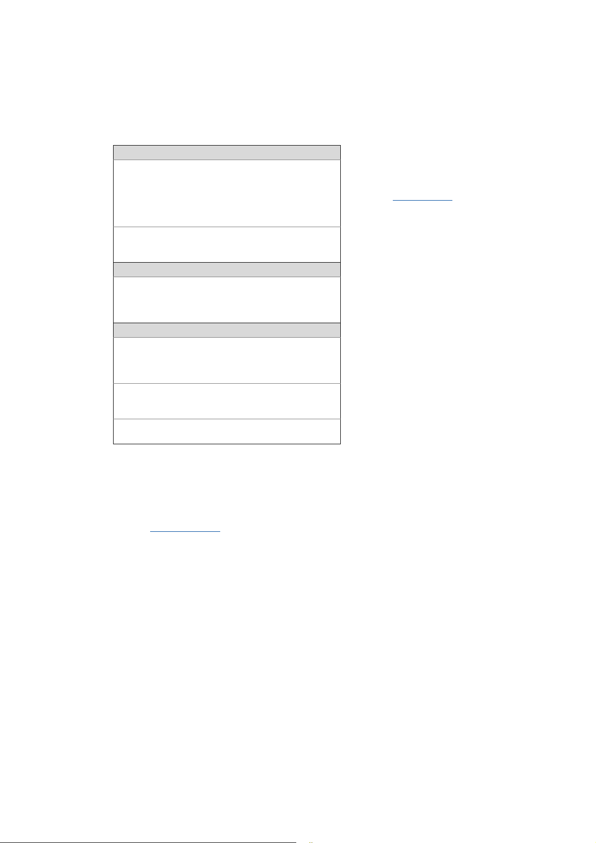
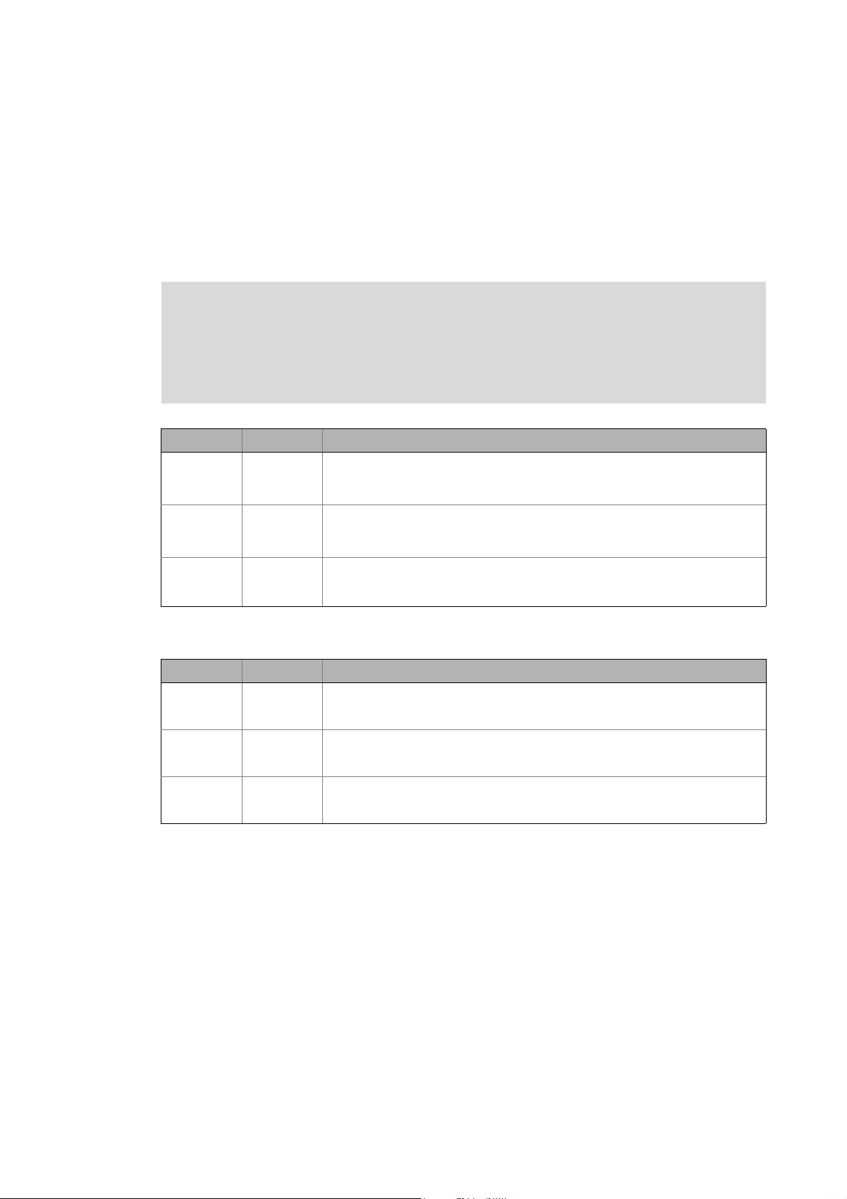
Documentation type Subject
System manuals System overview/sample topologies
• Controller-based Automation
• Visualising
Communication manuals
Online helps
Reference manuals
Online helps
Software manuals
Online helps
Bus systems
• Controller-based Automation EtherCAT®
• Controller-based Automation CANopen®
• Controller-based Automation PROFIBUS®
• Controller-based Automation PROFINET®
Lenze Controller:
• Controller 3200 C
• Controller c300
• Controller p300
• Controller p500
Lenze Engineering Tools:
• »PLC Designer«: Programming
• »Engineer«: Inverter configuration
• »VisiWinNET® Smart«: Visualisation
• »Backup & Restore«: Back up/restore data
4 Lenze · Controller-based Automation · PROFIBUS® Communication Manual · DMS 4.3 EN · 04/2014 · TD17
Page 5
1 About this documentation
_ _ _ _ _ _ _ _ _ _ _ _ _ _ _ _ _ _ _ _ _ _ _ _ _ _ _ _ _ _ _ _ _ _ _ _ _ _ _ _ _ _ _ _ _ _ _ _ _ _ _ _ _ _ _ _ _ _ _ _ _ _ _ _
More technical documentation for Lenze components
Further information on Lenze products which can be used in conjunction with Controller-based
Automation can be found in the following sets of documentation:
Mounting & wiring Symbols:
Mounting instructions
• Controller
• Communication cards (MC-xxx)
• I/O system 1000 (EPM-Sxxx)
• Inverter, Servo Drives
•Communication modules
Operating instructions
• Controller
• Servo system ECS (ECSxE, ECSxM)
Sample applications/Using application templates
Online help/software manuals
• Application Sample i700
• Application Samples
• ApplicationTemplate
Parameter setting, configuration, commissioning
Online help/reference manuals
•L-force Controller
• Inverter, Servo Drives
• I/O system 1000 (EPM-Sxxx)
Online help/communication manuals
• Bus systems
•Communication modules
Operating instructions
• Servo system ECS (ECSxE, ECSxM)
Printed documentation
Online help in the Lenze Engineering
Tool (also available as PDF file at
www.lenze.com
.)
Tip!
Current documentation and software updates with regard to Lenze products can be found
in the download area at:
www.lenze.com
Target group
This documentation is intended for persons who plan, install, commission and maintain the
networking of devices as part of the Lenze automation system "Controller-based Automation".
Information on validity
The information provided in this documentation is valid for the Lenze automation system
"Controller-based Automation" from version 3.
Screenshots/application examples
All screenshots in this documentation are application examples. Depending on the firmware
version of the field devices and the software version of the Engineering tools installed (e.g. »PLC
Designer« ), screenshots in this documentation may differ from the representation on the screen.
Lenze · Controller-based Automation · PROFIBUS® Communication Manual · DMS 4.3 EN · 04/2014 · TD17 5
Page 6

1 About this documentation
1.1 Document history
_ _ _ _ _ _ _ _ _ _ _ _ _ _ _ _ _ _ _ _ _ _ _ _ _ _ _ _ _ _ _ _ _ _ _ _ _ _ _ _ _ _ _ _ _ _ _ _ _ _ _ _ _ _ _ _ _ _ _ _ _ _ _ _
1.1 Document history
Version Description
1.0 05/2009 TD17 First edition
2.0 10/2009 TD17 General revision
3.0 10/2010 TD17 Commissioning and configuration with the Lenze »PLC Designer« V3.x
3.1 03/2011 TD17 Revision on the Lenze automation system"Controller-based Automation",
3.2 12/2011 TD17 Revision on the Lenze automation system"Controller-based Automation",
3.3 07/2012 TD17 Revision on the Lenze automation system"Controller-based Automation",
4.0 11/2012 TD17 General corrections
4.1 03/2013 TD17 Revision on the Lenze automation system"Controller-based Automation",
4.2 11/2013 TD17 Revision on the Lenze automation system"Controller-based Automation",
4.3 04/2014 TD17 Revision on the Lenze automation system"Controller-based Automation",
Release 3.1
release 3.2
release 3.3
New layout
Release 3.5
release 3.6
release 3.8
6
Lenze · Controller-based Automation · PROFIBUS® Communication Manual · DMS 4.3 EN · 04/2014 · TD17
Page 7
1 About this documentation
1.2 Conventions used
_ _ _ _ _ _ _ _ _ _ _ _ _ _ _ _ _ _ _ _ _ _ _ _ _ _ _ _ _ _ _ _ _ _ _ _ _ _ _ _ _ _ _ _ _ _ _ _ _ _ _ _ _ _ _ _ _ _ _ _ _ _ _ _
1.2 Conventions used
This documentation uses the following conventions to distinguish different types of information:
Type of information Identification Examples/notes
Numbers
Decimal Normal spelling Example: 1234
Decimal separator Point In general, the decimal point is used.
Example: 1234.56
Hexadecimal 0x[0 ... 9, A ... F] Example: 0x60F4
Binary
• Nibble
Text
Program name » « PC software
Window italics The message window... / The Options dialog box ...
Variable name Setting bEnable to TRUE...
Control element Bold The OK button ... / The Copy command ... / The Properties
Sequence of menu
commands
Shortcut <Bold> Use <F1> to open the online help.
Program code Courier IF var1 < var2 THEN
Keyword Courier bold
Hyperlink Underlined
Icons
Page reference ( 7) Optically highlighted reference to another page. Can be
Step-by-step instructions
0b[0, 1] Example: ’0b0110’
Example: ’0b0110.0100’
Example: Lenze »Engineer«
tab ... / The Name input field ...
If several successive commands are required for
executing a function, the individual commands are
separated from each other by an arrow: Select the
command File
If a key combination is required for a command, a "+" is
placed between the key identifiers: With
<Shift>+<ESC>...
a = a + 1
END IF
Optically highlighted reference to another topic. Can be
activated with a mouse-click in this documentation.
activated with a mouse-click in this documentation.
Step-by-step instructions are marked by a pictograph.
Open to...
Lenze · Controller-based Automation · PROFIBUS® Communication Manual · DMS 4.3 EN · 04/2014 · TD17 7
Page 8
1 About this documentation
1.3 Terminology used
_ _ _ _ _ _ _ _ _ _ _ _ _ _ _ _ _ _ _ _ _ _ _ _ _ _ _ _ _ _ _ _ _ _ _ _ _ _ _ _ _ _ _ _ _ _ _ _ _ _ _ _ _ _ _ _ _ _ _ _ _ _ _ _
1.3 Terminology used
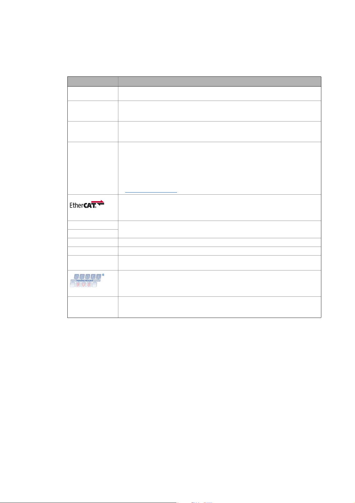
Term Meaning
Code Parameter for parameterising or monitoring the field device. The term is also referred to as
Controller The controller is the central component of the automation system which controls the Logic
Engineering PC The Engineering PC and the Engineering tools installed serve to configure and parameterise
Engineering tools Lenze software solutions for simply engineering in all phases:
Fieldbus stations Controller (PLC) and inverter integrated in the bus system (PROFIBUS)
Field device
GSD / GSE Device data base file (device description for PROFIBUS stations)
Inverter Generic term for Lenze frequency inverters, Servo Inverters
PLC Programmable Logic Controller
Subcode If a code contains several parameters, they are stored in so-called "subcodes".
"index" in common usage.
and Motion functionalities (by means of the runtime software).
The controller communicates with the field devices via the fieldbus.
the system.
The Engineering PC communicates with the controller via Ethernet.
•»EASY Starter«
• »Engineer«
•»PLC Designer«
•»WebConfig«
•»VisiWinNET®«
•»IPC Backup & Restore«
Lenze Engineering tools
EtherCAT® (Ethernet for Controller and Automation Technology) is an Ethernet-based
fieldbus system which meets the application profile for industrial real-time systems.
EtherCAT® is a registered trademark and patented technology, licensed by Beckhoff
Automation GmbH, Germany.
(German designation: SPS - Speicherprogrammierbare Steuerung)
PROFIBUS® (Process Fieldbus) is a common fieldbus system for the automation of machines
and production lines.
PROFIBUS® is a registered trademark and patented technology licensed by the PROFIBUS &
PROFINET International user organisation (PI).
This manual uses a slash "/" as a separator between code and subcode (e.g. "C00118/3").
In normal usage, the term is also referred to as "Subindex".
( 21)
8
Lenze · Controller-based Automation · PROFIBUS® Communication Manual · DMS 4.3 EN · 04/2014 · TD17
Page 9
1 About this documentation
1.4 Definition of the notes used
_ _ _ _ _ _ _ _ _ _ _ _ _ _ _ _ _ _ _ _ _ _ _ _ _ _ _ _ _ _ _ _ _ _ _ _ _ _ _ _ _ _ _ _ _ _ _ _ _ _ _ _ _ _ _ _ _ _ _ _ _ _ _ _
1.4 Definition of the notes used
The following signal words and symbols are used in this documentation to indicate dangers and
important information:
Safety instructions
Layout of the safety instructions:
Pictograph and signal word!
(characterises the type and severity of danger)
Note
(describes the danger and suggests how to prevent dangerous situations)
Pictograph Signal word Meaning
Danger! Danger of personal injury through dangerous electrical voltage
Danger! Danger of personal injury through a general source of danger
Stop! Danger of damage to material assets
Application notes
Refere nce to an i mmin ent d ange r tha t may resu lt in deat h or serio us pe rsonal in jury
if the corresponding measures are not taken.
Refere nce to an i mmin ent d ange r tha t may resu lt in deat h or serio us pe rsonal in jury
if the corresponding measures are not taken.
Reference to a possible danger that may result in damage to material assets if the
corresponding measures are not taken.
Pictograph Signal word Meaning
Note! Important note to ensure trouble-free operation
Tip! Useful tip for easy handling
Reference to other documentation
Lenze · Controller-based Automation · PROFIBUS® Communication Manual · DMS 4.3 EN · 04/2014 · TD17 9
Page 10

2 Safety instructions
_ _ _ _ _ _ _ _ _ _ _ _ _ _ _ _ _ _ _ _ _ _ _ _ _ _ _ _ _ _ _ _ _ _ _ _ _ _ _ _ _ _ _ _ _ _ _ _ _ _ _ _ _ _ _ _ _ _ _ _ _ _ _ _
2 Safety instructions
Observe the following safety instructions if you want to commission an inverter or a system with
the Lenze Controller.
Read the documentation supplied with the system components carefully before you
start commissioning the devices and the Lenze Controller!
The system manual contains safety instructions which must be observed!
Danger!
Risk of injury
There is risk of injury by ...
• unpredictable motor movements (e.g. an unintended direction of rotation, too high
speeds, or jerky movement);
• impermissible operating states during the parameterisation while there is an active
online connection to the device.
Possible consequences
Death or severe injuries
Protective measures
• If required, provide systems with installed inverters with additional monitoring and
protective devices according to the safety regulations valid in each case (e.g. law on
technical equipment, regulations for the prevention of accidents).
• During commissioning, maintain an adequate safety distance to the motor or the
machine parts driven by the motor.
Stop!
Damage or destruction of machine parts
Damage or destruction of machine parts can be caused by ...
• unpredictable motor movements (e.g. an unintended direction of rotation, too high
speeds, or jerky movement);
• impermissible operating states during the parameterisation while there is an active
online connection to the device.
Possible consequences
Damage or destruction of machine parts
Protective measures
If required, provide systems with installed inverters with additional monitoring and
protective devices according to the safety regulations valid in each case (e.g. law on
technical equipment, regulations for the prevention of accidents).
10 Lenze · Controller-based Automation · PROFIBUS® Communication Manual · DMS 4.3 EN · 04/2014 · TD17
Page 11
3 Controller-based Automation: Central motion control
_ _ _ _ _ _ _ _ _ _ _ _ _ _ _ _ _ _ _ _ _ _ _ _ _ _ _ _ _ _ _ _ _ _ _ _ _ _ _ _ _ _ _ _ _ _ _ _ _ _ _ _ _ _ _ _ _ _ _ _ _ _ _ _
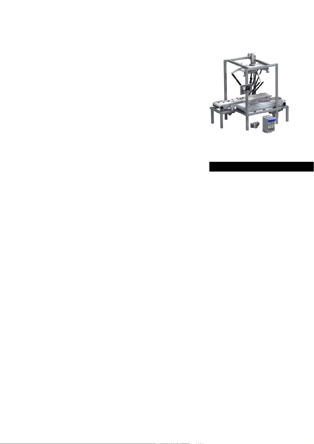
3 Controller-based Automation: Central motion control
The Lenze automation system "Controller-based Automation" serves to create complex automation
solutions with central motion control. Here, the Controller is the control centre of the system.
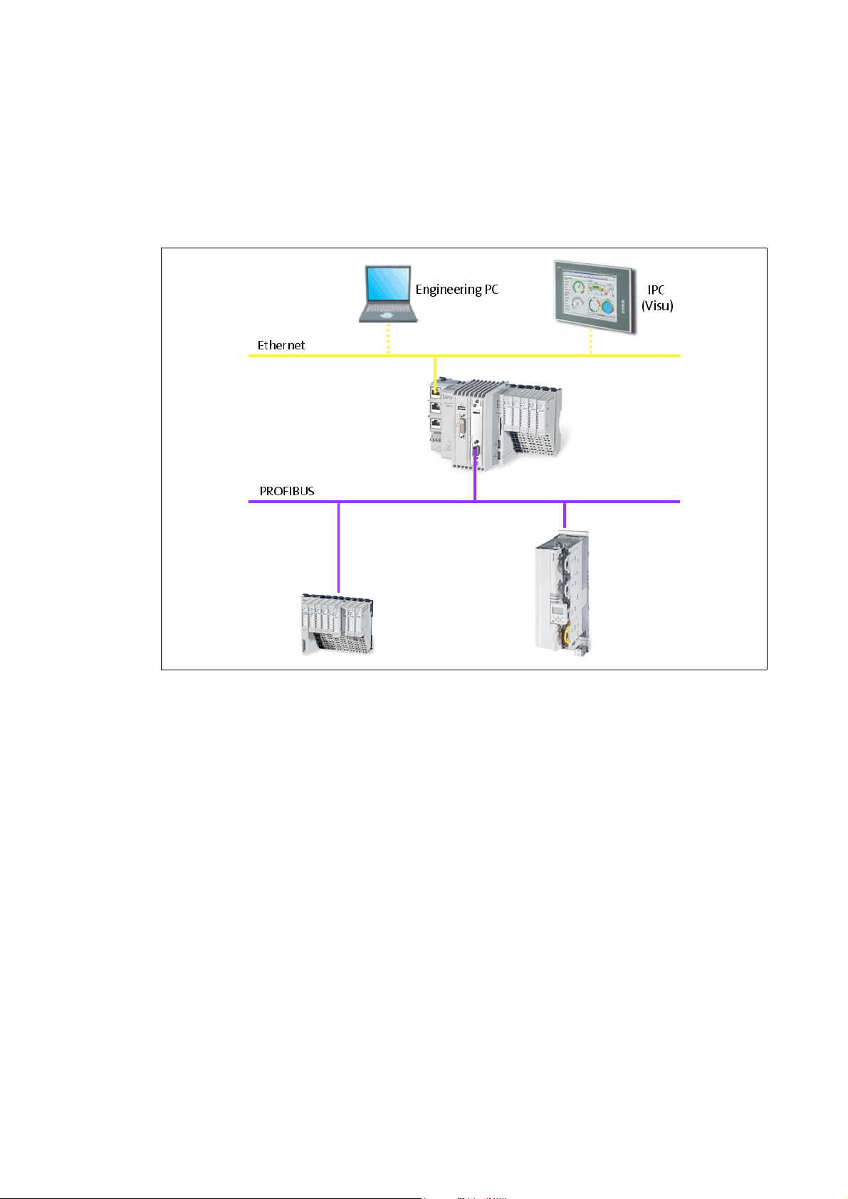
System structure of the Controller-based Automation: "All from one single source"
[3-1] Example: PROFIBUS with the 3231 C Lenze Controller (I/O system 1000 and Servo Drive 9400 as slaves)
Lenze · Controller-based Automation · PROFIBUS® Communication Manual · DMS 4.3 EN · 04/2014 · TD17 11
Page 12

3 Controller-based Automation: Central motion control
_ _ _ _ _ _ _ _ _ _ _ _ _ _ _ _ _ _ _ _ _ _ _ _ _ _ _ _ _ _ _ _ _ _ _ _ _ _ _ _ _ _ _ _ _ _ _ _ _ _ _ _ _ _ _ _ _ _ _ _ _ _ _ _
Lenze provides especially coordinated system components:
• Engineering software
The Lenze Engineering tools
to parameterise, configure and diagnose the system. The Engineering PC communicates with
the Controller via Ethernet.
•Controller
The Lenze Controller is available as Panel Controller with integrated touch display and as
Cabinet Controller in control cabinet design.
Cabinet Controllers provide a direct coupling of the I/O system 100 via the integrated backplane
bus.
The runtime software of the Lenze Controllers provides the control and/or visualisation of
motion sequences. The following software versions are available:
• "Logic": Sequence control in the Controller, motion control in the inverter
• "Motion": Sequence control and motion control in the Controller, inverter as actuating drive
• "Visu": Optional visualisation of the automation system, can be used separately or in addition
to "Logic" or "Motion"
An external monitor panel/display can be connected to the Cabinet Controller 3231 C/
3241 C.
• Without software: Controller as single component with operating system only
•Bus systems
EtherCAT is a standard "on board" bus system of the Controller-based Automation. EtherCAT
enables the control of all nodes (Motion/Logic) on one common fieldbus.
Optionally, CANopen, PROFIBUS and PROFINET can be used as extended topologies.
The Controllers c300/p300 have a CANopen interface "on board" as well (in addition to
EtherCAT).
• Inverter (e.g. Servo Inverter i700)
( 21) on your Engineering PC (Windows operating system ) serve
"Logic & Motion" runtime software
The "Controller-based Automation" system allows for the central control of devices for Logic and
Motion applications. The runtime software runs on the Controller.
In case of Logic applications, the sequence control is carried out in the Controller and the motion
control is carried out in the inverter.
In case of Motion applications , the sequence control and motion control are carried out in the
Controller. The inverter is used as actuating drive.
• Motion applications make special demands on the cycle time and real-time capability of the bus
system between the Controller and the subordinate fieldbus nodes.
• this is for instance the case if the field devices, for example, are to move in a synchronised way
or if position setpoints are to be transmitted.
12 Lenze · Controller-based Automation · PROFIBUS® Communication Manual · DMS 4.3 EN · 04/2014 · TD17
Page 13
3 Controller-based Automation: Central motion control
_ _ _ _ _ _ _ _ _ _ _ _ _ _ _ _ _ _ _ _ _ _ _ _ _ _ _ _ _ _ _ _ _ _ _ _ _ _ _ _ _ _ _ _ _ _ _ _ _ _ _ _ _ _ _ _ _ _ _ _ _ _ _ _
Fieldbus communication
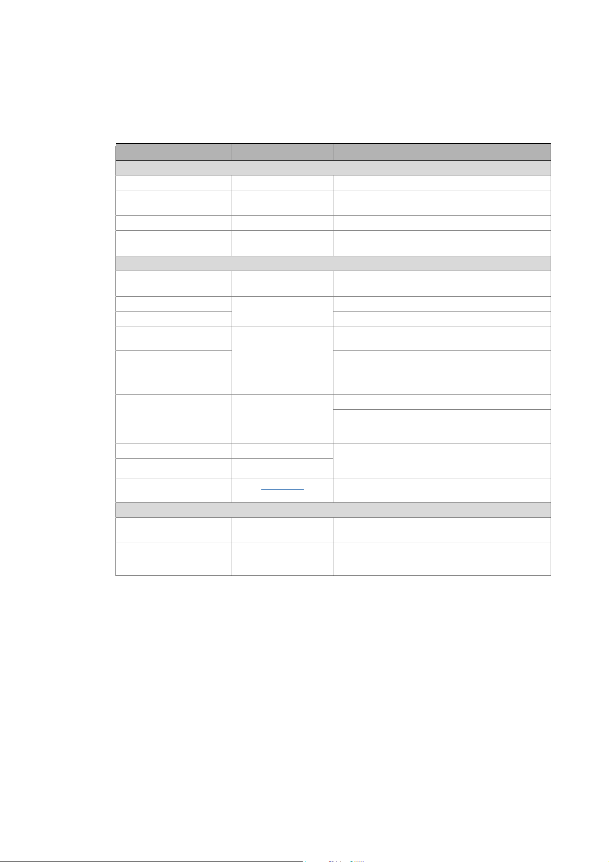
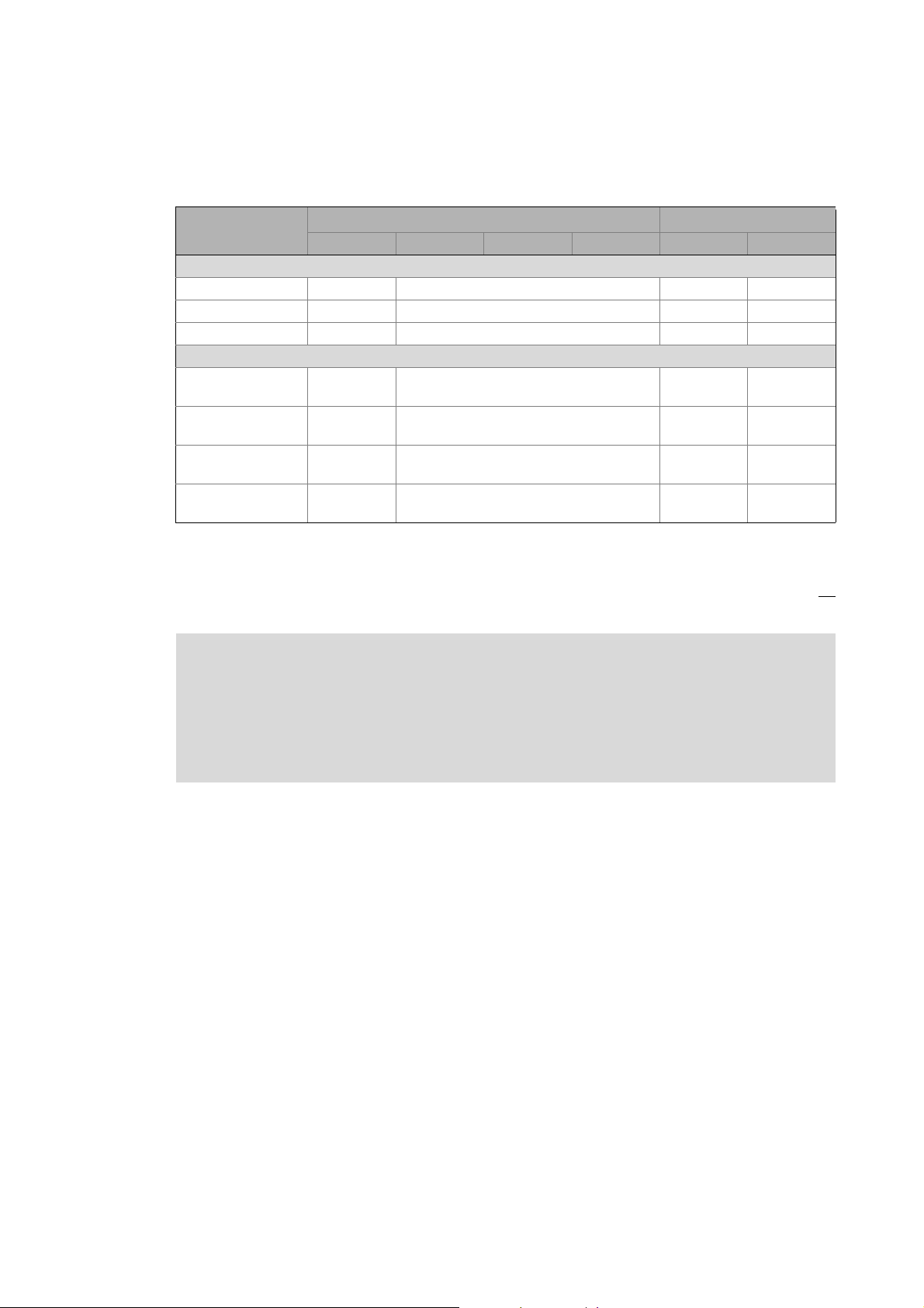
The Lenze Controllers have different interfaces for fieldbus communication:
Area Cabinet Controller Panel Controller
c300 3221 C 3231 C 3241 C p300 p500
Interfaces (on board)
Ethernet1212
EtherCAT 1
CANopen 1
Optional interfaces (communication cards)
CANopen
MC-CAN2
PROFIBUS master
MC-PBM
PROFIBUS slave
MC-PBS
PROFINET device
MC-PND
1)
2)
- -
- -
- -
- -
11
-1
1)
2)
1
-
1) In preparation
2) Only the CAN master functionality is supported.
The Ethernet interface serves to connect the Engineering PC or to create line topologies (no
integrated switch for Controller c300/p300).
More information on the bus systems and configuration can be found in the
communication manuals:
• Controller-based Automation EtherCAT®
• Controller-based Automation CANopen®
• Controller-based Automation PROFIBUS®
• Controller-based Automation PROFINET®
Lenze · Controller-based Automation · PROFIBUS® Communication Manual · DMS 4.3 EN · 04/2014 · TD17 13
Page 14

4 The Lenze automation system with PROFIBUS
4.1 Brief description of PROFIBUS
_ _ _ _ _ _ _ _ _ _ _ _ _ _ _ _ _ _ _ _ _ _ _ _ _ _ _ _ _ _ _ _ _ _ _ _ _ _ _ _ _ _ _ _ _ _ _ _ _ _ _ _ _ _ _ _ _ _ _ _ _ _ _ _
4 The Lenze automation system with PROFIBUS
Note!
In the Lenze automation system PROFIBUS is exclusively used as Logic bus.
The Motion functionality is not supported when PROFIBUS is used. Always use EtherCAT
to connect inverters to be controlled via the central motion functionality.
Mixed operation PROFIBUS with EtherCAT
This chapter provides basic information about ...
• the structure of the Lenze automation system using the PROFIBUS bus system;
• the Lenze Engineering tools required for commissioning;
• the interaction of the components.
4.1 Brief description of PROFIBUS
Today, PROFIBUS is the most commonly used fieldbus system. As it comes with the widest range of
various field devices, PROFIBUS is occasionally prioritised over more modern bus systems. Due to the
low bandwidth and synchronisation mechanisms, PROFIBUS is only provided as a logic bus as part
of the Lenze automation system.
We recommend using PROFIBUS for the following applications:
• Equipment and extension of system parts that have already been automated with PROFIBUS
before.
• Use of field devices that are not available for e.g. EtherCAT or CANopen.
• Combination of PROFIBUS as logic bus and EtherCAT as logic/motion bus
Tip!
Detailed information about PROFIBUS can be found on the website of the PROFIBUS &
PROFINET user organisation:
( 42)
14
www.profibus.com
Lenze · Controller-based Automation · PROFIBUS® Communication Manual · DMS 4.3 EN · 04/2014 · TD17
Page 15
4 The Lenze automation system with PROFIBUS
4.1 Brief description of PROFIBUS
_ _ _ _ _ _ _ _ _ _ _ _ _ _ _ _ _ _ _ _ _ _ _ _ _ _ _ _ _ _ _ _ _ _ _ _ _ _ _ _ _ _ _ _ _ _ _ _ _ _ _ _ _ _ _ _ _ _ _ _ _ _ _ _
4.1.1 Structure of the PROFIBUS system
[4-1] Example: PROFIBUS with the 3231 C Lenze Controller (I/O system 1000 and Servo Drive 9400 as slaves)
In the example (Fig. [4-1]), the 3231 C Lenze Controller is the PROFIBUS master. It can communicate
with one or several stations (slaves).
PROFIBUS has an internal line topology (without repeater) or a tree topology (with repeater).
Basic wiring of PROFIBUS
The PROFIBUS network must be terminated at the first and last station. The bus terminating resistor
is integrated into the bus connector and is activated by a switch.
Using the Lenze Controller as a PROFIBUS slave
Using the MC-PBS communication card, the Lenze Controllers can also be applied as PROFIBUS
slaves.
( 17)
Tip!
A sample project for operation of a 3200 C controller as PROFIBUS slave can be found in the
"Download" area at www.Lenze.com
Application Knowledge Base: All articles Application Ideas Pool Controller 3200 C
:
Lenze · Controller-based Automation · PROFIBUS® Communication Manual · DMS 4.3 EN · 04/2014 · TD17 15
Page 16

4 The Lenze automation system with PROFIBUS
4.1 Brief description of PROFIBUS
_ _ _ _ _ _ _ _ _ _ _ _ _ _ _ _ _ _ _ _ _ _ _ _ _ _ _ _ _ _ _ _ _ _ _ _ _ _ _ _ _ _ _ _ _ _ _ _ _ _ _ _ _ _ _ _ _ _ _ _ _ _ _ _
Parameter setting
The PROFIBUS stations can be parameterised in different ways.
If field devices are used the parameters of which are completely written to an GSD/GSE file,
PROFIBUS can only be configured with the »PLC Designer«:
• Import of the PROFIBUS slaves' GSD/GSE files into the »PLC Designer« project.
• Set-up of the control configuration and creation of the PLC program
If PROFIBUS configuration is only possible via a PROFIdrive parameter channel, the
parameterisation can also be done using the »Engineer«/»EASY Starter« – depending on the device
type via the following interfaces:
•Ethernet
•CAN
• Diagnostic interface
Note!
The "L-force Controller as gateway" function is not available in combination with
PROFIBUS. Therefore logging in with the »Engineer« via the controller as gateway is not
possible.
16
Lenze · Controller-based Automation · PROFIBUS® Communication Manual · DMS 4.3 EN · 04/2014 · TD17
Page 17
4 The Lenze automation system with PROFIBUS
M
Z
Z
S SS
1
M
Z
Z
S SS
Z
Z
Z
Z
1 23
R
S S
R
4.1 Brief description of PROFIBUS
_ _ _ _ _ _ _ _ _ _ _ _ _ _ _ _ _ _ _ _ _ _ _ _ _ _ _ _ _ _ _ _ _ _ _ _ _ _ _ _ _ _ _ _ _ _ _ _ _ _ _ _ _ _ _ _ _ _ _ _ _ _ _ _
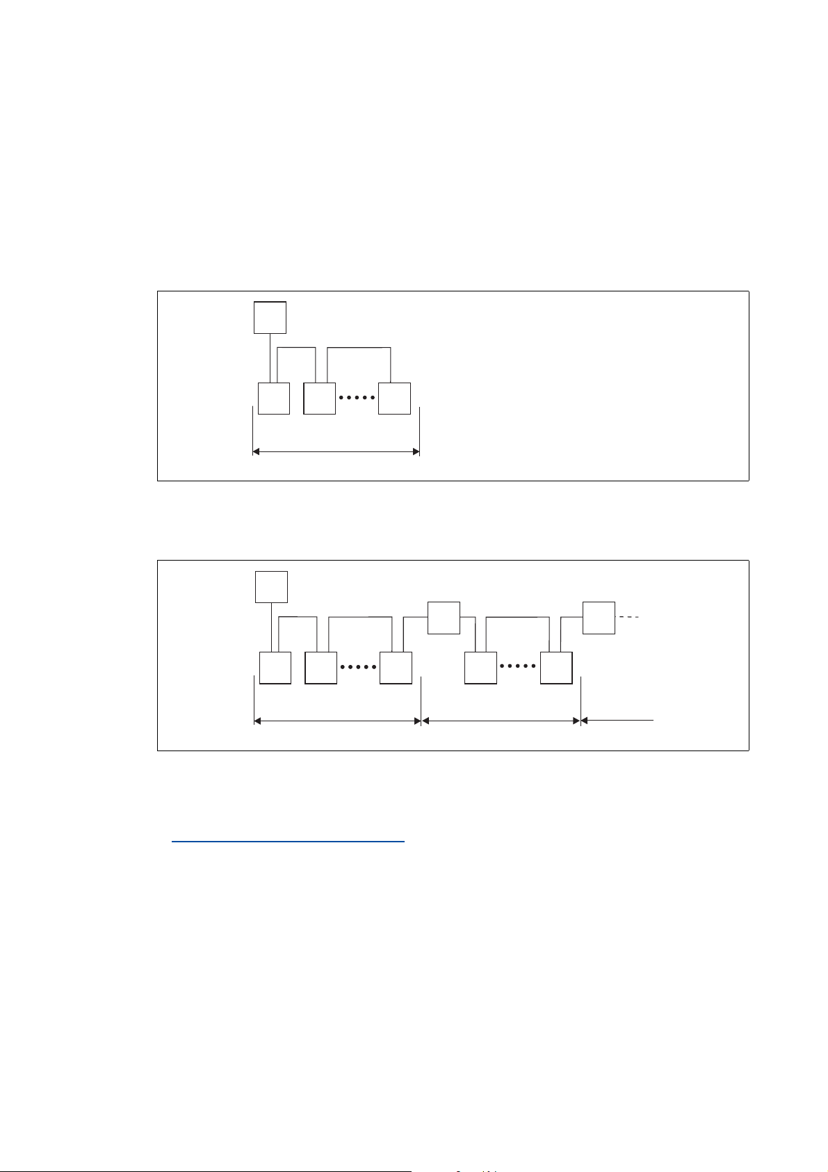
4.1.2 Basic wiring of PROFIBUS
Two simple RS485 networks are described in the following examples.
Each segment of the network must be terminated at both ends. The bus terminators of the
PROFIBUS are marked with a "Z" in each one of the following examples.
In the case of an RS485 network consisting of only one segment, the network starts at the PROFIBUS
master (M) with the integrated bus terminating resistor and ends at the last PROFIBUS station (S);
its bus terminating resistor in the bus connector must be activated.
[4-2] PROFIBUS network with one segment
A PROFIBUS network consisting of several segments contains repeaters (R) for connecting the
segments. The repeaters are provided with integrated bus terminating resistors.
[4-3] PROFIBUS network with repeaters
If you do not use a repeater at the end of the segment, the bus terminating resistor in the bus
connector of the last device must be activated.
Activating the bus terminating resistor
( 26)
E94YCPM012a
E94YCPM012b
Lenze · Controller-based Automation · PROFIBUS® Communication Manual · DMS 4.3 EN · 04/2014 · TD17 17
Page 18

4 The Lenze automation system with PROFIBUS
M
123
SS S S S
RR
4.1 Brief description of PROFIBUS
_ _ _ _ _ _ _ _ _ _ _ _ _ _ _ _ _ _ _ _ _ _ _ _ _ _ _ _ _ _ _ _ _ _ _ _ _ _ _ _ _ _ _ _ _ _ _ _ _ _ _ _ _ _ _ _ _ _ _ _ _ _ _ _
Number of nodes
2133PFB004
[4-4] Number of nodes
Segment Master (M) Slave (S) Repeater (R)
1131-
230-
2-301
3-301
Tip!
Repeaters do not have a station address. When calculating the maximum number of
stations, they reduce the number of stations by 1 on each side of the segment.
By means of repeaters, you can establish line or tree topologies. The maximum total
dimension of the bus system depends on ...
• the used baud rate;
• the number of repeaters.
18
Lenze · Controller-based Automation · PROFIBUS® Communication Manual · DMS 4.3 EN · 04/2014 · TD17
Page 19

4 The Lenze automation system with PROFIBUS
4.1 Brief description of PROFIBUS
_ _ _ _ _ _ _ _ _ _ _ _ _ _ _ _ _ _ _ _ _ _ _ _ _ _ _ _ _ _ _ _ _ _ _ _ _ _ _ _ _ _ _ _ _ _ _ _ _ _ _ _ _ _ _ _ _ _ _ _ _ _ _ _
4.1.3 Field devices
The Lenze automation system supports the following PROFIBUS-capable Logic components:
Logic field devices
Controller Controller 32xx C
Controller c300
Controller p300
Controller p500
Servo Drives 9400 1) HighLine
Highline with CiA402
PLC
Regenerative power supply module
Inverter Drives 8400 2) StateLine
HighLine
TopLine
I/O-System 1000 EPM-Sxxx
1) With PROFIBUS communication module E94AYCPM
2) With PROFIBUS communication module E84AYCPM
Field devices of other manufacturers can be implemented if corresponding device descriptions are
available.
Lenze · Controller-based Automation · PROFIBUS® Communication Manual · DMS 4.3 EN · 04/2014 · TD17 19
Page 20

4 The Lenze automation system with PROFIBUS
0
1
3
2
PROFIBUS
MC-PBx
SYS
ST0
ST1
ST2
5
4
4.2 PROFIBUS hardware for Lenze Controllers
_ _ _ _ _ _ _ _ _ _ _ _ _ _ _ _ _ _ _ _ _ _ _ _ _ _ _ _ _ _ _ _ _ _ _ _ _ _ _ _ _ _ _ _ _ _ _ _ _ _ _ _ _ _ _ _ _ _ _ _ _ _ _ _
4.2 PROFIBUS hardware for Lenze Controllers
MC-PBM / MC-PBS communication card
•The MC-PBM communication card serves to connect a Lenze Controller as PROFIBUS master to
a PROFIBUS network.
•The MC-PBS communication card serves to connect a Lenze Controller as PROFIBUS slave to a
PROFIBUS network.
Using the Lenze Controller as a PROFIBUS slave
( 15)
A Front panel
B Printed circuit board
C Coding
D Connection of Lenze Controller
E PROFIBUS connection
F LED status displays of the MC-PBM
communication card ( 47)
MC-PBx-001
[4-5] MC-PBM / MC-PBS communication card
Technical data of the MC-PBM / MC-PBS communication card ( 22)
Use
The MC-PBM / MC-PBS communication card is installed in the respective slot of the Lenze
Controller.
Example: Lenze Controller 3231 C with MC-PBM communication card
LED status displays of the MC-PBS
communication card ( 48)
( 23)
20
MC-PBM MC-PBM communication card
PBM1 PROFIBUS connection
( 23)
Lenze · Controller-based Automation · PROFIBUS® Communication Manual · DMS 4.3 EN · 04/2014 · TD17
Page 21

4 The Lenze automation system with PROFIBUS
4.3 Lenze Engineering tools
_ _ _ _ _ _ _ _ _ _ _ _ _ _ _ _ _ _ _ _ _ _ _ _ _ _ _ _ _ _ _ _ _ _ _ _ _ _ _ _ _ _ _ _ _ _ _ _ _ _ _ _ _ _ _ _ _ _ _ _ _ _ _ _
4.3 Lenze Engineering tools
The Lenze Engineering tools enable the configuration and operation of controller-based Lenze
automation systems according to individual requirements.
Use the corresponding Engineering tool applicable to the field device.
»EASY Navigator«
The »EASY Navigator« provides an overview of the Lenze Engineering software installed on the
Engineering PC.
The Lenze Engineering software consists of the Engineering tools optimised for the respective
application case.
The »EASY Navigator« ...
• simplifies orientation for selecting the suitable Engineering tool;
• allows for the simple start of the required Engineering tool (depending on the application):
What would you like to do? Button Engineering tool
Programming
• Parameterise the Lenze Controller
• Parameterise the i700 servo inverter
• Parameterise the I/O system 1000
Configuring the inverter
• Projecting the automation/drive system
• Parameterisation/configuration
• Inverter Drives 8400, 8400 motec/protec
• Servo Drives 9400
• I/O-System 1000
Visualising
• Visualising the automation system
• Creating the user interface
Online diagnostics
Easy online diagnostics of Lenze Controllers and
other Lenze field devices
»PLC Designer«
»Engineer«
»VisiWinNET«
»EASY Starter«
Online parameterisation
• Online parameterisation and commissioning
• Direct online parameterisation when the online
connection to the Lenze devices is active.
»EASY Starter«
Further Engineering tools that are not called via the »EASY Navigator« are:
• »WebConfig« (web-based parameterisation, configuration, and online diagnostics)
• »IPC Backup & Restore« (data backup, data recovery).
Lenze · Controller-based Automation · PROFIBUS® Communication Manual · DMS 4.3 EN · 04/2014 · TD17 21
Page 22

5Technical data
5.1 Technical data of the MC-PBM / MC-PBS communication card
_ _ _ _ _ _ _ _ _ _ _ _ _ _ _ _ _ _ _ _ _ _ _ _ _ _ _ _ _ _ _ _ _ _ _ _ _ _ _ _ _ _ _ _ _ _ _ _ _ _ _ _ _ _ _ _ _ _ _ _ _ _ _ _
5 Technical data
5.1 Technical data of the MC-PBM / MC-PBS communication card
Area Values
Protocol PROFIBUS-DP (V0, V1), ISO 7498
Communication medium RS485
Network topology • Line terminated on both sides (without repeater)
• Tree (with repeaters)
Type within the network • MC-PBM: Master
• MC-PBS: Slave
Baud rate See "Bus cable length
Bus length
Connection 9-pin Sub-D socket
" ( 24)
I/O data of MC-PBM (master)
Area Values
Number of DP-V0/DP-V1 slaves supported Max. 125
Cyclic output data Max. 3584 bytes
(status information is treated separately)
Total cyclic input data Max. 3584 bytes
Total cyclic output data Max. 3584 bytes
Cyclic input data per slave Max. 244 bytes/slave
Cyclic output data per slave Max. 244 bytes/slave
Configuration data Max. 244 bytes/slave
In the »PLC Designer« control configuration, a maximum of 125 PROFIBUS slaves (devices) can be
appended below a PROFIBUS master.
For each slave, a maximum of 244 input bytes and 244 output bytes, respectively, can be
transferred. Their data type is irrelevant in this context.
I/O data of MC-PBS (slave)
Area Values
Cyclic input data Max. 244 bytes
Cyclic output data Max. 244 bytes
Acyclic reading/writing Max. 240 bytes
Configuration data Max. 244 bytes
Application-specific parameter data 237 bytes
22
In the »PLC Designer« control configuration, a maximum of 24 I/O modules can be appended below
a PROFIBUS slave. It is irrelevant whether the modules in question are input or output modules, or
of which data type (BYTE, WORD) they are.
Lenze · Controller-based Automation · PROFIBUS® Communication Manual · DMS 4.3 EN · 04/2014 · TD17
Page 23

5Technical data
1
6
5
9
5.1 Technical data of the MC-PBM / MC-PBS communication card
_ _ _ _ _ _ _ _ _ _ _ _ _ _ _ _ _ _ _ _ _ _ _ _ _ _ _ _ _ _ _ _ _ _ _ _ _ _ _ _ _ _ _ _ _ _ _ _ _ _ _ _ _ _ _ _ _ _ _ _ _ _ _ _
PROFIBUS connection
By means of the 9-pin Sub-D socket you can connect the communication card with the bus system.
View Pin Assignment Description
1Not assigned-
2Not assigned-
3 RxD/TxD-P Data line B (received data/transmitted data, plus)
4 RTS Request To Send (received data/transmitted data, no
5 M5V2 Data ground (ground to 5 V)
6 P5V2 5 V DC / 30 mA (bus termination)
7Not assigned-
8 RxD/TxD-N Data line A (received data/transmitted data, minus)
9Not assigned-
differential signal)
Lenze · Controller-based Automation · PROFIBUS® Communication Manual · DMS 4.3 EN · 04/2014 · TD17 23
Page 24

5Technical data
5.2 Bus cable specification
_ _ _ _ _ _ _ _ _ _ _ _ _ _ _ _ _ _ _ _ _ _ _ _ _ _ _ _ _ _ _ _ _ _ _ _ _ _ _ _ _ _ _ _ _ _ _ _ _ _ _ _ _ _ _ _ _ _ _ _ _ _ _ _
5.2 Bus cable specification
Note!
Only use cables that comply with the specifications of the PROFIBUS user organisation.
Area Values
Cable resistance 135 ... 165 /km, (f = 3 ... 20 MHz)
Capacitance per unit length 30 nF/km
Loop resistance < 110 /km
Core diameter > 0.64 mm
Core cross-section > 0.34 mm
Cores Twisted in pairs, insulated and shielded
PROFIBUS cables with an integrated bus terminating resistor can be obtained from various cable
manufacturers.
2
Bus cable length
The length of the bus cable depends on the baud rate used:
Baud rate Length
9.6 ... 93.75 kbps 1200 m
187.5 kbps 1000 m
500 kbps 400 m
1500 kbps 200 m
3000 ... 12000 kbps 100 m
Note!
The baud rate depending on the data volume, cycle time and number of stations should
only be selected as high as required for the application.
24
Lenze · Controller-based Automation · PROFIBUS® Communication Manual · DMS 4.3 EN · 04/2014 · TD17
Page 25

6 Commissioning of PROFIBUS
6.1 Overview of the commissioning steps
_ _ _ _ _ _ _ _ _ _ _ _ _ _ _ _ _ _ _ _ _ _ _ _ _ _ _ _ _ _ _ _ _ _ _ _ _ _ _ _ _ _ _ _ _ _ _ _ _ _ _ _ _ _ _ _ _ _ _ _ _ _ _ _
6 Commissioning of PROFIBUS
Note!
Via PROFIBUS only Logic Field devices ( 19) can be operated in the Lenze automation
system.
Inverters which are to be controlled via the central Motion functionality must always be
connected via EtherCAT.
Mixed operation PROFIBUS with EtherCAT
This chapter provides information on how to commission the Lenze automation system with
PROFIBUS.
Depending on the field devices used, the following Lenze Engineering tools
• »EASY Starter«
• »Engineer«
•»PLC Designer«
6.1 Overview of the commissioning steps
The main commissioning steps are listed in the following table:
Step Activity Software to be used
1. Planning the bus topology
2. Installing field devices
3. Create a project folder
4. Commissioning the field devices
5. Creating a PLC program with a target system (Logic/Motion)
6. Configuring the communication parameters ( 30)
7. Importing missing devices / device description files
8. Creating a control configuration (adding field devices)
9. Configuration of the PROFIBUS master ( 37)
10. Configuring the PROFIBUS slave
11. Compiling the PLC program code
12. Logging in on the controller with the »PLC Designer«
With the log-in, the fieldbus configuration and the PLC program are
loaded into the Controller.
13. Starting the PLC program
( 26)
( 26)
( 27)
( 27) »Engineer« / »EASY Starter«
( 40)
( 41)
( 41)
( 42)
( 21) are required:
( 28) »PLC Designer«
( 32)
( 33)
( 41)
Lenze · Controller-based Automation · PROFIBUS® Communication Manual · DMS 4.3 EN · 04/2014 · TD17 25
Page 26

6 Commissioning of PROFIBUS
6.2 Detailed commissioning steps
_ _ _ _ _ _ _ _ _ _ _ _ _ _ _ _ _ _ _ _ _ _ _ _ _ _ _ _ _ _ _ _ _ _ _ _ _ _ _ _ _ _ _ _ _ _ _ _ _ _ _ _ _ _ _ _ _ _ _ _ _ _ _ _
6.2 Detailed commissioning steps
In the following sections, the individual commissioning steps are described.
Follow the instructions of these sections step by step in order to commission your system.
More detailed information about how to work with the Lenze Engineering tools can be
found in the corresponding manuals and online helps.
6.2.1 Planning the bus topology
Before installing a PROFIBUS network, make a diagram of the network.
Note!
Observe the connection between bus cable length and baud rate.
Bus cable length
How to plan the bus topology for your configuration
1. Create an overview of the planned PROFIBUS network with all field devices to be
integrated.
2. Start with the Lenze Controller (master).
3. Add the other field devices (slaves) below.
6.2.2 Installing field devices
For the installation of a field device, follow the mounting instructions for the respective device.
Activating the bus terminating resistor
PROFIBUS must be terminated at the first and last physical station by a bus terminating resistor.
The bus terminating resistor in the bus connector of the bus cable is activated by means of a switch.
PROFIBUS cables with an integrated bus terminating resistor can be obtained from various cable
manufacturers.
Note!
( 24)
26
If you want to disconnect individual bus stations, ensure that the bus terminators at the
cable ends remain active.
Please observe that the bus termination is not active any longer if ...
• the bus connector has been disconnected;
• the voltage supply of the field device has been disconnected.
Lenze · Controller-based Automation · PROFIBUS® Communication Manual · DMS 4.3 EN · 04/2014 · TD17
Page 27

6 Commissioning of PROFIBUS
6.2 Detailed commissioning steps
_ _ _ _ _ _ _ _ _ _ _ _ _ _ _ _ _ _ _ _ _ _ _ _ _ _ _ _ _ _ _ _ _ _ _ _ _ _ _ _ _ _ _ _ _ _ _ _ _ _ _ _ _ _ _ _ _ _ _ _ _ _ _ _
6.2.3 Create a project folder
Create a project folder on the Engineering PC.
Use this project folder to store the data generated in the following different project configuration
steps:
• Project data created in the »Engineer« or »EASY Starter«
• The project file created in the »PLC Designer«
Tip!
Create a separate project folder for every PROFIBUS configuration and store the project
files.
6.2.4 Commissioning the field devices
Parameterise the Lenze field devices connected to the PROFIBUS network by means of the
»Engineer« or »EASY Starter«.
PROFIBUS is exclusively configured using the »PLC Designer«.
PROFIBUS settings of the field devices which have possibly been carried out with the »Engineer«/
»EASY Starter« are overwritten.
Documentation of the Lenze field devices
Detailed information about the commissioning of the Lenze field devices is provided
here.
Tip!
We recommend to commission each field device individually and then integrate them into
the PLC program.
Lenze · Controller-based Automation · PROFIBUS® Communication Manual · DMS 4.3 EN · 04/2014 · TD17 27
Page 28

6 Commissioning of PROFIBUS
6.2 Detailed commissioning steps
_ _ _ _ _ _ _ _ _ _ _ _ _ _ _ _ _ _ _ _ _ _ _ _ _ _ _ _ _ _ _ _ _ _ _ _ _ _ _ _ _ _ _ _ _ _ _ _ _ _ _ _ _ _ _ _ _ _ _ _ _ _ _ _
6.2.5 Creating a PLC program with a target system (Logic/Motion)
By means of the »PLC Designer« you can map the network topology in the control configuration.
Tip!
In the »PLC Designer«, PROFIBUS stations and stations of other fieldbus systems can be
configured.
Mixed operation PROFIBUS with EtherCAT
( 42)
How to create a PLC program in the »PLC Designer«:
1. Use the menu command File New project to create a new »PLC Designer« project.
2. Select "Standard project" in the New project dialog box.
A "Standard project" simplifies the structure of a project in the »PLC Designer«; for instance,
a device tree structure with a target system, PLC logic, etc. is provided.
• Go to the Name input field and enter a name for your »PLC Designer« project.
• Select the previously created project folder as storage location in the Location
selection field.
Create a project folder
3. Confirm the entries by clicking OK.
( 27)
28
Lenze · Controller-based Automation · PROFIBUS® Communication Manual · DMS 4.3 EN · 04/2014 · TD17
Page 29

6 Commissioning of PROFIBUS
6.2 Detailed commissioning steps
_ _ _ _ _ _ _ _ _ _ _ _ _ _ _ _ _ _ _ _ _ _ _ _ _ _ _ _ _ _ _ _ _ _ _ _ _ _ _ _ _ _ _ _ _ _ _ _ _ _ _ _ _ _ _ _ _ _ _ _ _ _ _ _
4. Go to the Standard project dialog window and select the target system in the Device
selection field:
• Lenze Logic Controller
For actuating controllers that execute simple movements, have no Motion functionality,
or are controlled via pure PLC functionalities.
• Lenze Motion Controller
Only if an additional Motion bus with EtherCAT is used (see Mixed operation PROFIBUS
with EtherCAT ( 42))
Further optional project settings
Selection of the Lenze control technology release version
Selection of the compiler version
Selection of the programming language:
• Sequential function chart (SFC)
• Instruction list (IL)
• Continuous Function Chart (CFC)
• Function block diagram (FBD)
• Ladder diagram (LD)
• Structured text (ST)
5. Confirm the selection by clicking OK.
Lenze · Controller-based Automation · PROFIBUS® Communication Manual · DMS 4.3 EN · 04/2014 · TD17 29
Page 30

6 Commissioning of PROFIBUS
6.2 Detailed commissioning steps
_ _ _ _ _ _ _ _ _ _ _ _ _ _ _ _ _ _ _ _ _ _ _ _ _ _ _ _ _ _ _ _ _ _ _ _ _ _ _ _ _ _ _ _ _ _ _ _ _ _ _ _ _ _ _ _ _ _ _ _ _ _ _ _
6.2.6 Configuring the communication parameters
Set the communication parameters to establish an online connection to the Lenze Controller later
on.
How to configure the communication parameters
1. Go to the Communication settings tab of the target system (device, Lenze Controller ...) and
click the Add gateway button.
Then go to the Gateway dialog box and enter the IP address of the controller. (By
double-clicking the predefined value it can be overwritten.)
2. Confirm the entry by clicking OK.
30
Lenze · Controller-based Automation · PROFIBUS® Communication Manual · DMS 4.3 EN · 04/2014 · TD17
Page 31

6 Commissioning of PROFIBUS
6.2 Detailed commissioning steps
_ _ _ _ _ _ _ _ _ _ _ _ _ _ _ _ _ _ _ _ _ _ _ _ _ _ _ _ _ _ _ _ _ _ _ _ _ _ _ _ _ _ _ _ _ _ _ _ _ _ _ _ _ _ _ _ _ _ _ _ _ _ _ _
3. Click the Scan network button.
4. Select the suitable controller for the IP address entered under 2. and activate it by
means of the Set active path button (or by double-click).
5. Now you can carry out the following actions using the »PLC Designer«:
Logging in on the controller with the »PLC Designer«
( 41)
Lenze · Controller-based Automation · PROFIBUS® Communication Manual · DMS 4.3 EN · 04/2014 · TD17 31
Page 32

6 Commissioning of PROFIBUS
6.2 Detailed commissioning steps
_ _ _ _ _ _ _ _ _ _ _ _ _ _ _ _ _ _ _ _ _ _ _ _ _ _ _ _ _ _ _ _ _ _ _ _ _ _ _ _ _ _ _ _ _ _ _ _ _ _ _ _ _ _ _ _ _ _ _ _ _ _ _ _
6.2.7 Importing missing devices / device description files
The device description file contains the data of the fieldbus peripherals required for the master
control. This file is required to program the control system.
With the »PLC Designer«, device descriptions for the following Lenze device series are installed as
well:
• i700 servo inverter
• Servo Drives 9400
• Inverter Drives 8400
• I/O system 1000 (EPM-Sxxx)
• Fieldbus communication cards for Lenze Controllers
(EtherCAT, CANopen, PROFIBUS, PROFINET)
In order to furthermore integrate missing devices or devices of other manufacturers, the
corresponding device description files of the manufacturer are required.
In the »PLC Designer« you can import device description files of the *.XML, *.devdesc.XML, *.EDS,
*.DCF, and *.GSx type via the menu command Tools Device Repository....
Tip!
Current device description files for Lenze devices can be found in the "Download" area at:
www.lenze.com
32
Lenze · Controller-based Automation · PROFIBUS® Communication Manual · DMS 4.3 EN · 04/2014 · TD17
Page 33

6 Commissioning of PROFIBUS
6.2 Detailed commissioning steps
_ _ _ _ _ _ _ _ _ _ _ _ _ _ _ _ _ _ _ _ _ _ _ _ _ _ _ _ _ _ _ _ _ _ _ _ _ _ _ _ _ _ _ _ _ _ _ _ _ _ _ _ _ _ _ _ _ _ _ _ _ _ _ _
6.2.8 Creating a control configuration (adding field devices)
Note!
The configuration of a PROFIBUS network must be created in the »PLC Designer«, since,
during the start-up of the Lenze Controller, the complete configuration is written to the
slaves connected. Settings that have been made previously in the slaves will be
overwritten.
How to create the control configuration in the »PLC Designer«:
1. Go to the context menu of the target system (device, Lenze Controller ...) and use the
Add device command in order to extend the control configuration by the
PROFIBUS master (PROFIBUS MC-PBM).
Lenze · Controller-based Automation · PROFIBUS® Communication Manual · DMS 4.3 EN · 04/2014 · TD17 33
Page 34

6 Commissioning of PROFIBUS
6.2 Detailed commissioning steps
_ _ _ _ _ _ _ _ _ _ _ _ _ _ _ _ _ _ _ _ _ _ _ _ _ _ _ _ _ _ _ _ _ _ _ _ _ _ _ _ _ _ _ _ _ _ _ _ _ _ _ _ _ _ _ _ _ _ _ _ _ _ _ _
2. Go to the context menu of the PROFIBUS (master) and execute the Add device command.
34
Lenze · Controller-based Automation · PROFIBUS® Communication Manual · DMS 4.3 EN · 04/2014 · TD17
Page 35

6 Commissioning of PROFIBUS
6.2 Detailed commissioning steps
_ _ _ _ _ _ _ _ _ _ _ _ _ _ _ _ _ _ _ _ _ _ _ _ _ _ _ _ _ _ _ _ _ _ _ _ _ _ _ _ _ _ _ _ _ _ _ _ _ _ _ _ _ _ _ _ _ _ _ _ _ _ _ _
3. Go to the "Add device" dialog box, select the respective slave field device from the
selection list and use the Add device button to add it below the PROFIBUS master.
You can only select those devices the PROFIBUS device description file of which has been
imported in the »PLC Designer«.
Importing missing devices / device description files
4. Repeat the Add Device command until all slaves connected to the fieldbus are included
in the control configuration.
• In the control configuration, a maximum of 125 PROFIBUS slaves (devices) can be
appended below a PROFIBUS master.
• For each slave, a maximum of 244 input bytes and 244 output bytes, respectively, can be
transferred. Their data type is irrelevant in this context.
( 32)
Lenze · Controller-based Automation · PROFIBUS® Communication Manual · DMS 4.3 EN · 04/2014 · TD17 35
Page 36

6 Commissioning of PROFIBUS
6.2 Detailed commissioning steps
_ _ _ _ _ _ _ _ _ _ _ _ _ _ _ _ _ _ _ _ _ _ _ _ _ _ _ _ _ _ _ _ _ _ _ _ _ _ _ _ _ _ _ _ _ _ _ _ _ _ _ _ _ _ _ _ _ _ _ _ _ _ _ _
5. Assign appropriate names to the added slaves (e. g. "Drive_vertical_L9400_HighLine").
The names must …
• only contain the characters "A ... Z", "a ... z", "0 ... 9" or "_";
• not begin with a digit.
You can enter a name by clicking the element.
Example:
36
Lenze · Controller-based Automation · PROFIBUS® Communication Manual · DMS 4.3 EN · 04/2014 · TD17
Page 37

6 Commissioning of PROFIBUS
6.2 Detailed commissioning steps
_ _ _ _ _ _ _ _ _ _ _ _ _ _ _ _ _ _ _ _ _ _ _ _ _ _ _ _ _ _ _ _ _ _ _ _ _ _ _ _ _ _ _ _ _ _ _ _ _ _ _ _ _ _ _ _ _ _ _ _ _ _ _ _
6.2.9 Configuration of the PROFIBUS master
How to configure the PROFIBUS master:
1. Set the DP parameters for the PROFIBUS master (PROFIBUS MC-PBM).
Setting Description
Station address PROFIBUS master station address
• The standard setting is ’0’.
• Only change the setting if the address is not supposed to be ’0’. If
required, you must also manually adapt the station addresses of the
slaves.
• Each station address in a PROFIBUS network must be unique (it must only
appear once).
Highest station address The standard setting is ’125’.
(Max. number of PROFIBUS nodes = 126)
Baud rate Set the baud rate depending on the Bus cable length
Default setting By removing the checkmark you can manually change the parameter values
in the "Values" column of the table.
Groups This button serves to create up to eight device groups.
( 24).
Lenze · Controller-based Automation · PROFIBUS® Communication Manual · DMS 4.3 EN · 04/2014 · TD17 37
Page 38

6 Commissioning of PROFIBUS
6.2 Detailed commissioning steps
_ _ _ _ _ _ _ _ _ _ _ _ _ _ _ _ _ _ _ _ _ _ _ _ _ _ _ _ _ _ _ _ _ _ _ _ _ _ _ _ _ _ _ _ _ _ _ _ _ _ _ _ _ _ _ _ _ _ _ _ _ _ _ _
For each group, select whether it is supposed to be operated in the freeze mode and/or sync
mode. By assigning the slaves to different groups (on the DP Parameters tab of the DP
slaves, Groups... button), you can synchronise the data exchange from the master via a
global control command.
A freeze command causes a master, a slave, or a group, to "freeze" the input in the current
status and transfer these data in the next data exchange process.
A sync command causes the slaves to connect the data received by the master through to
the outputs synchronously regarding time with the next sync command.
In order to activate or deactivate the freeze and sync mode for one group, you can either set
a checkmark at the corresponding place in the table or remove it. Besides, you can change
the names of the groups here.
38
Lenze · Controller-based Automation · PROFIBUS® Communication Manual · DMS 4.3 EN · 04/2014 · TD17
Page 39

6 Commissioning of PROFIBUS
6.2 Detailed commissioning steps
_ _ _ _ _ _ _ _ _ _ _ _ _ _ _ _ _ _ _ _ _ _ _ _ _ _ _ _ _ _ _ _ _ _ _ _ _ _ _ _ _ _ _ _ _ _ _ _ _ _ _ _ _ _ _ _ _ _ _ _ _ _ _ _
2. Especially in the case of mixed operation with EtherCAT, we recommend selecting a special
bus cycle task on the Profibus DP I/O Mapping tab of the PROFIBUS master (PROFIBUS MCPBM).
The "Cycle settings of the higher-level bus" serve to use the bus cycle task set via the PLC
settings tab of the Lenze Controller (device):
Lenze · Controller-based Automation · PROFIBUS® Communication Manual · DMS 4.3 EN · 04/2014 · TD17 39
Page 40

6 Commissioning of PROFIBUS
6.2 Detailed commissioning steps
_ _ _ _ _ _ _ _ _ _ _ _ _ _ _ _ _ _ _ _ _ _ _ _ _ _ _ _ _ _ _ _ _ _ _ _ _ _ _ _ _ _ _ _ _ _ _ _ _ _ _ _ _ _ _ _ _ _ _ _ _ _ _ _
6.2.10 Configuring the PROFIBUS slave
Set the DP Parameters for the PROFIBUS slave.
• The PROFIBUS slave station address is automatically assigned after adding the slave to the
control configuration tree. The PROFIBUS master receives the station address ’0’, the first slave
the address ’1’, the second slave the address ’2’, and so on.
Do only change this setting if the station addresses shall deviate from the standard setting. If
required, you must manually adapt the station addresses of the other PROFIBUS stations, too.
Each station address in a PROFIBUS network must be unique (it must only appear once).
• You do not have to set a baud rate, as the slave automatically recognises the baud rate.
•By means of the Groups... button, you can assign the slave to one (or several) device
group(s).
• We recommend not to change the other standard settings.
40
Lenze · Controller-based Automation · PROFIBUS® Communication Manual · DMS 4.3 EN · 04/2014 · TD17
Page 41

6 Commissioning of PROFIBUS
6.2 Detailed commissioning steps
_ _ _ _ _ _ _ _ _ _ _ _ _ _ _ _ _ _ _ _ _ _ _ _ _ _ _ _ _ _ _ _ _ _ _ _ _ _ _ _ _ _ _ _ _ _ _ _ _ _ _ _ _ _ _ _ _ _ _ _ _ _ _ _
6.2.11 Compiling the PLC program code
In order to compile the PLC program code, select the menu command Build Build, or press
function key <F11>.
• If errors have occurred during the compilation process, you can locate and eliminate them by
means of the »PLC Designer« error messages.
Then re-translate the program code.
• If no errors have occurred during the compilation process, save the »PLC Designer« project in the
project folder.
6.2.12 Logging in on the controller with the »PLC Designer«
Use the menu command Online Login or <Alt>+<F8> to log in on the Lenze Controller.
• For this, the PLC program must be error-free.
• With the log-in, the fieldbus configuration and the PLC program are loaded to the controller.
Any possibly available configuration and PLC program are overwritten.
6.2.13 Starting the PLC program
Before the start, the PLC program must be loaded to the Lenze Controller using the menu command
Online Login.
Use the menu command Debug Start or function key <F5> to start the PLC program.
Note!
• The fieldbus starts even if not all stations of the bus are available.
• If the PLC program is stopped (<Shift>+<F8>), the cyclic data transfer continues until
a "reset origin" is carried out (menu command Online Reset origin).
Lenze · Controller-based Automation · PROFIBUS® Communication Manual · DMS 4.3 EN · 04/2014 · TD17 41
Page 42

7 Mixed operation PROFIBUS with EtherCAT
_ _ _ _ _ _ _ _ _ _ _ _ _ _ _ _ _ _ _ _ _ _ _ _ _ _ _ _ _ _ _ _ _ _ _ _ _ _ _ _ _ _ _ _ _ _ _ _ _ _ _ _ _ _ _ _ _ _ _ _ _ _ _ _
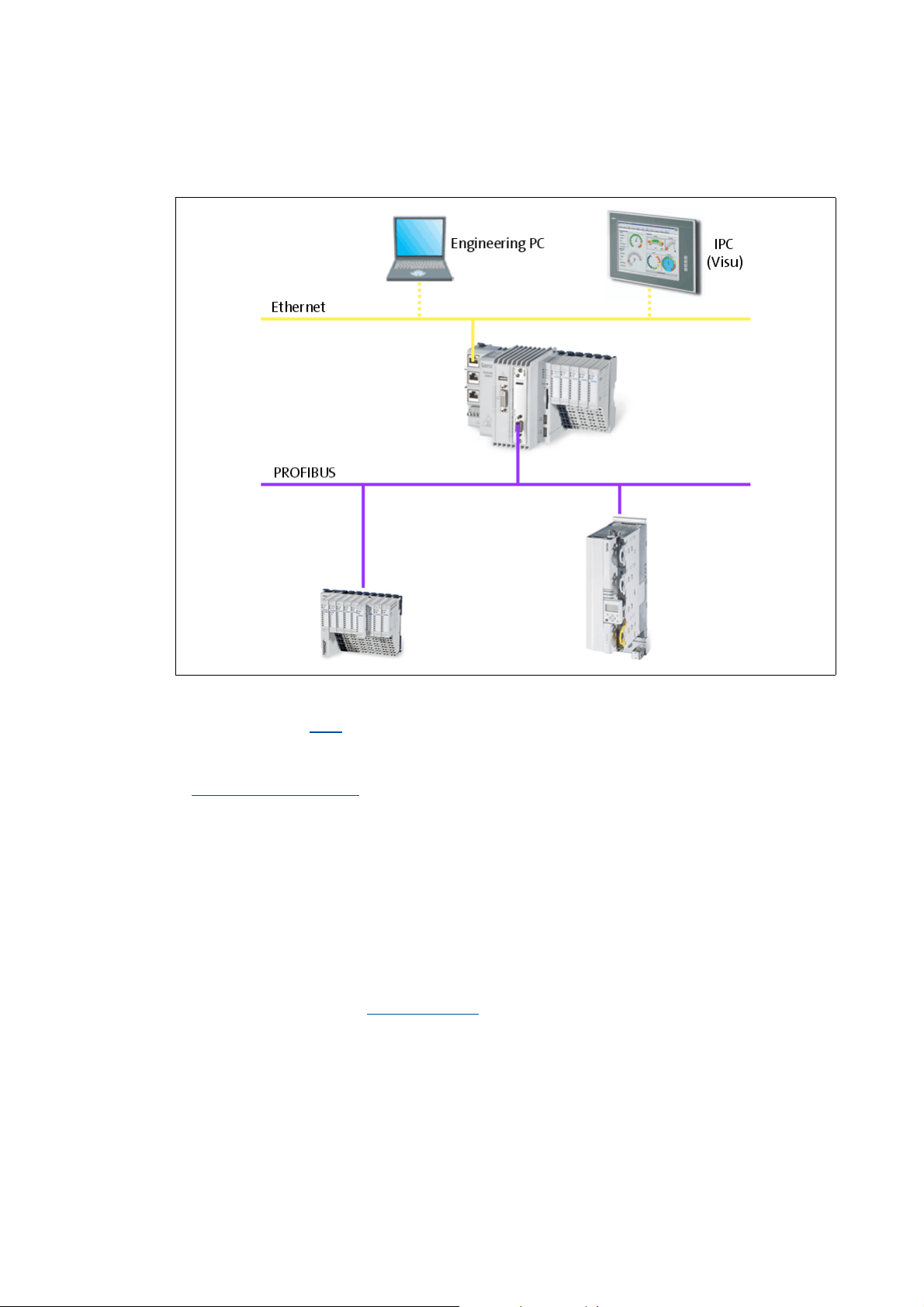
7 Mixed operation PROFIBUS with EtherCAT
[7-1] Example: Mixed operation of PROFIBUS with EtherCAT on the 3231 C Lenze Controller
Within the Lenze Controller-based Automation, PROFIBUS can be used in parallel to the EtherCAT
bus system. This is useful if not all field devices are available for the same bus system or if a Motion
bus (EtherCAT) is required in parallel to PROFIBUS.
The following combinations are permissible: PROFIBUS (Logic bus) and EtherCAT (Logic/Motion bus)
Controller-based Automation EtherCAT communication manual
Here you can find information on the commissioning of EtherCAT components.
42 Lenze · Controller-based Automation · PROFIBUS® Communication Manual · DMS 4.3 EN · 04/2014 · TD17
Page 43

8 Function libraries
8.1 CAA_Device_Diagnosis.lib function library
_ _ _ _ _ _ _ _ _ _ _ _ _ _ _ _ _ _ _ _ _ _ _ _ _ _ _ _ _ _ _ _ _ _ _ _ _ _ _ _ _ _ _ _ _ _ _ _ _ _ _ _ _ _ _ _ _ _ _ _ _ _ _ _
8 Function libraries
For configuring the PROFIBUS and for diagnostic purposes, the following function libraries are
available in the »PLC Designer«:
• CAA_Device_Diagnosis.lib
• IIoDrvDPV1C1.lib
8.1 CAA_Device_Diagnosis.lib function library
This library serves to query diagnostics information from the PROFIBUS master and the slaves.
Note!
The diagnostics information in the CAA_Device_Diagnosis.lib function library is
currently only partly available. You can only execute a diagnostics process if the node
works without errors or if there is a fault. Currently, the PLC does not provide any
detailed fault information.
8.2 IIoDrvDPV1C1.lib function library
The IIoDrvDPV1C1.lib function library supports the acyclic PROFIBUS DP-V1 - class 1 writing and
reading services for data transmission between the master and the slaves. The data are addressed
via slot and index within the slave nodes (see PROFIBUS-DP standard).
Codes or indexes can be read or written with the IoDrvDPV1_C1_M_Write and
IoDrvDPV1_C1_M_Read functions via DP-V1.
Lenze · Controller-based Automation · PROFIBUS® Communication Manual · DMS 4.3 EN · 04/2014 · TD17 43
Page 44

9 Defining the minimum cycle time of the PLC project
9.1 Determining the task utilisation of the application
_ _ _ _ _ _ _ _ _ _ _ _ _ _ _ _ _ _ _ _ _ _ _ _ _ _ _ _ _ _ _ _ _ _ _ _ _ _ _ _ _ _ _ _ _ _ _ _ _ _ _ _ _ _ _ _ _ _ _ _ _ _ _ _
9 Defining the minimum cycle time of the PLC project
This chapter provides information on how to ...
• Determining the task utilisation of the application
• Optimising the system
( 46)
9.1 Determining the task utilisation of the application
In the online mode, the Monitor tab of the Task Configuration shows current status details and
measurements of the cycles, cycle times, and jitters of the tasks contained.
( 44)
The values are updated in the same time interval as that used for monitoring the values from the
controller.
If the cursor is on a task nam e field, the values displayed can be reset to 0 by the Reset context menu
command (right-click the task name field).
44
Lenze · Controller-based Automation · PROFIBUS® Communication Manual · DMS 4.3 EN · 04/2014 · TD17
Page 45

9 Defining the minimum cycle time of the PLC project
9.1 Determining the task utilisation of the application
_ _ _ _ _ _ _ _ _ _ _ _ _ _ _ _ _ _ _ _ _ _ _ _ _ _ _ _ _ _ _ _ _ _ _ _ _ _ _ _ _ _ _ _ _ _ _ _ _ _ _ _ _ _ _ _ _ _ _ _ _ _ _ _
How to determine the task utilisation:
Initial situation: A complete project, e.g. with a PROFIBUS task and 2 lower priority tasks
has been created.
1. For a first measurement of the task utilisation, set the cycle times of all cyclic tasks
available in the PLC system "high" (e.g. PROFIBUS task = 10 ms, all other cyclic
tasks = 20 ms).
2. Use the menu command Online Login, or log in on the Lenze Controller with <Alt>+<F8>.
• For this, the PLC program must be error-free.
• With the log-in, the fieldbus configuration and the PLC program are loaded into the
Controller.
3. Reset the values displayed on the Monitor tab of the Task Configuration to 0 after the
complete run-up of the system.
Execute the Reset command from the context menu of the task name field.
4. Read the displayed maximum computing time of the task with the highest priority.
In the illustration above, the max. cycle time of the PROFIBUS task is 647 μs.
The minimum cycle time (T
Note!
A safety factor of 1.5 should be included in the calculation.
) for a system can be calculated by means of the formula:
min
T
= Task utilisation x safety factor
min
Lenze · Controller-based Automation · PROFIBUS® Communication Manual · DMS 4.3 EN · 04/2014 · TD17 45
Page 46

9 Defining the minimum cycle time of the PLC project
9.2 Optimising the system
_ _ _ _ _ _ _ _ _ _ _ _ _ _ _ _ _ _ _ _ _ _ _ _ _ _ _ _ _ _ _ _ _ _ _ _ _ _ _ _ _ _ _ _ _ _ _ _ _ _ _ _ _ _ _ _ _ _ _ _ _ _ _ _
9.2 Optimising the system
How to optimise the system:
1. Use the menu command Online Login, or log in on the Lenze Controller with <Alt>+<F8>.
• For this, the PLC program must be error-free.
• With the log-in, the fieldbus configuration and the PLC program are loaded into the
Controller.
2. Check the task processing times.
3. Optimising the cycle times:
• If technologically required, the cycle times of the remaining tasks with lower priorities
can be decreased.
• Condition: No task with a low priority must assign more than 60 percent of the
corresponding cycle time in its task utilisation.
46
Lenze · Controller-based Automation · PROFIBUS® Communication Manual · DMS 4.3 EN · 04/2014 · TD17
Page 47

10 Diagnostics
10.1 LED status displays of the MC-PBM communication card
_ _ _ _ _ _ _ _ _ _ _ _ _ _ _ _ _ _ _ _ _ _ _ _ _ _ _ _ _ _ _ _ _ _ _ _ _ _ _ _ _ _ _ _ _ _ _ _ _ _ _ _ _ _ _ _ _ _ _ _ _ _ _ _
10 Diagnostics
The PROFIBUS field devices, communication modules, and the MC-PBM and MC-PBS
communication cards have LED status displays for diagnostics.
Furthermore, the »PLC Designer« provides a function library for diagnosing PROFIBUS.
Documentation of the field devices / PROFIBUS communication modules
Here you'll find some detailed information on the LED status displays of the field devices
and communication modules.
10.1 LED status displays of the MC-PBM communication card
[10-1] LED status displays
LED Colour State Description
SYS Green On Communication active (cyclic data exchange with at least one
Yellow Blinking once per
- Off No voltage supply or hardware is defective.
ST0 - Off No function
ST1 - Off No function
ST2 Red On The device has a communication problem with at least one
Yellow On The device holds the PROFIBUS token and can transmit telegrams.
- Off No PROFIBUS communication
MC-PBx-001_LED
PROFIBUS station
Blinking 5 times per
second (5 Hz)
Blinking irregularly • Starting action: Missing or faulty configuration
second (1 Hz)
Blinking 5 times per
second (5 Hz)
Blinking irregularly A hardware or severe system error has been detected.
Blinking irregularly The device is part of the PROFIBUS network and shares the token
No error in the configuration:
Communication is stopped or the device is ready for communication.
However, there is no connection to a slave.
• Runtime: Host watchdog time error
The device is in bootstrap loader mode and is waiting for the
firmware download
The firmware download is executed.
PROFIBUS slave or has detected a short circuit.
with other PROFIBUS master devices.
Lenze · Controller-based Automation · PROFIBUS® Communication Manual · DMS 4.3 EN · 04/2014 · TD17 47
Page 48

10 Diagnostics
10.2 LED status displays of the MC-PBS communication card
_ _ _ _ _ _ _ _ _ _ _ _ _ _ _ _ _ _ _ _ _ _ _ _ _ _ _ _ _ _ _ _ _ _ _ _ _ _ _ _ _ _ _ _ _ _ _ _ _ _ _ _ _ _ _ _ _ _ _ _ _ _ _ _
10.2 LED status displays of the MC-PBS communication card
MC-PBx-001_LED
[10-2] LED status displays
LED Colour State Description
SYS Green On Communication active
(cyclic data exchange with the PROFIBUS master)
Blinking 5 times per
second (5 Hz)
Blinking irregularly • Starting action: Missing or faulty configuration
Yellow Blinking once per
- Off No voltage supply or hardware is defective.
ST0 - Off No function
ST1 - Off No function
ST2 Red On The application program (bus-synchronous/device-controlled
Yellow On The slave has received parameter/configuration data from the
- Off No PROFIBUS communication
second (1 Hz)
Blinking 5 times per
second (5 Hz)
Blinking irregularly A hardware or severe system error has been detected.
No communication
(no cyclic data exchange with the PROFIBUS master)
• Runtime: Host watchdog time error
The device is in bootstrap loader mode and is waiting for the
firmware download
The firmware download is executed.
communication mode) is no longer synchronous with the bus cycle.
PROFIBUS master and is in the "DataExchange" state".
("DataExchange" state not reached)
48
Lenze · Controller-based Automation · PROFIBUS® Communication Manual · DMS 4.3 EN · 04/2014 · TD17
Page 49

10 Diagnostics
10.3 Diagnostics in the »PLC Designer«
_ _ _ _ _ _ _ _ _ _ _ _ _ _ _ _ _ _ _ _ _ _ _ _ _ _ _ _ _ _ _ _ _ _ _ _ _ _ _ _ _ _ _ _ _ _ _ _ _ _ _ _ _ _ _ _ _ _ _ _ _ _ _ _
10.3 Diagnostics in the »PLC Designer«
For the diagnostics of PROFIBUS, the »PLC Designer« provides the CAA_Device_Diagnosis.lib
function library.
Note!
The diagnostics information in the CAA_Device_Diagnosis.lib function library is
currently only partly available. You can only execute a diagnostics process if the node
works without errors or if there is a fault. Currently, the PLC does not provide any
detailed fault information.
Lenze · Controller-based Automation · PROFIBUS® Communication Manual · DMS 4.3 EN · 04/2014 · TD17 49
Page 50

11 Parameter reference
_ _ _ _ _ _ _ _ _ _ _ _ _ _ _ _ _ _ _ _ _ _ _ _ _ _ _ _ _ _ _ _ _ _ _ _ _ _ _ _ _ _ _ _ _ _ _ _ _ _ _ _ _ _ _ _ _ _ _ _ _ _ _ _
11 Parameter reference
This chapter complements the parameter list in the online help of the Lenze Controller by the
parameters of the MC-PBM / MC-PBS communication card.
These parameters ...
• are for instance shown in the Lenze »WebConfig« (Engineering tool for web-based
parameterisation);
• are listed in numerically ascending order.
C1031
C1032
C1033
C1034
Parameter | Name:
C1031 | Device: type key
Identification of the card
Read access Write access CINH PLC-STOP No transfer
Parameter | Name:
C1032 | Device: type version
Version number of the card
Read access Write access CINH PLC-STOP No transfer
Parameter | Name:
C1033 | Device: name
Device name of the card
Read access Write access CINH PLC-STOP No transfer
Parameter | Name:
C1034 | Device: software revision
Software version of the card
Read access Write access CINH PLC-STOP No transfer
Data type: VISIBLE_STRING
Index: 23544 = 0x5BF8
Data type: VISIBLE_STRING
Index: 23543 = 0x5BF7
Data type: VISIBLE_STRING
Index: 23542 = 0x5BF6
Data type: VISIBLE_STRING
Index: 23541 = 0x5BF5
C1035
Parameter | Name:
C1035 | Device: hardware revision
Data type: VISIBLE_STRING
Index: 23540 = 0x5BF4
Hardware version of the card
Read access Write access CINH PLC-STOP No transfer
C1036
Parameter | Name:
C1036 | Device: serial number
Data type: VISIBLE_STRING
Index: 23539 = 0x5BF3
Serial number of the card
Read access Write access CINH PLC-STOP No transfer
50 Lenze · Controller-based Automation · PROFIBUS® Communication Manual · DMS 4.3 EN · 04/2014 · TD17
Page 51

11 Parameter reference
_ _ _ _ _ _ _ _ _ _ _ _ _ _ _ _ _ _ _ _ _ _ _ _ _ _ _ _ _ _ _ _ _ _ _ _ _ _ _ _ _ _ _ _ _ _ _ _ _ _ _ _ _ _ _ _ _ _ _ _ _ _ _ _
C1037
C1038
Parameter | Name:
C1037 | Device: manufacturer
Manufacturer of the card
Read access Write access CINH PLC-STOP No transfer
Parameter | Name:
C1038 | Device: manufacturing date
Manufacturing date of the card
Read access Write access CINH PLC-STOP No transfer
Data type: VISIBLE_STRING
Index: 23538 = 0x5BF2
Data type: VISIBLE_STRING
Index: 23537 = 0x5BF1
Lenze · Controller-based Automation · PROFIBUS® Communication Manual · DMS 4.3 EN · 04/2014 · TD17 51
Page 52

Index
Index
_ _ _ _ _ _ _ _ _ _ _ _ _ _ _ _ _ _ _ _ _ _ _ _ _ _ _ _ _ _ _ _ _ _ _ _ _ _ _ _ _ _ _ _ _ _ _ _ _ _ _ _ _ _ _ _ _ _ _ _ _ _ _ _
A
Activating the bus terminating resistor 26
Adding devices 33
Adding field devices 33
Application notes 9
B
Baud rate 24
Brief description of PROFIBUS 14
Bus cable length 24
C
C1031 | Device: Identification 50
C1032 | Device: Version 50
C1033 | Device: Name 50
C1034 | Device: Software version 50
C1035 | Device: Hardware version 50
C1036 | Device: Serial number 50
C1037 | Device: Manufacturer 51
C1038 | Device: Manufacturing date 51
CAA_Device_Diagnosis.lib 43
CAA_Device_Diagnosis.lib function library 43
Cable specification of bus cable 24
Codes 50
Commissioning of PROFIBUS 25
Commissioning the field devices 27
Communication medium 22
Communication Settings 30
Compiling the PLC program code 41
Configuration of the PROFIBUS master 37
Configuring the communication parameters 30
Configuring the PROFIBUS slave 40
Conventions used 7
Create a project folder 27
Creating a control configuration 33
Creating a PLC program with a target system (Logic/Motion) 28
Creating a target system (Logic/Motion) 28
E
EASY Navigator 21
E-mail to Lenze 54
Engineering software 21
Engineering tools 21
F
Feedback to Lenze 54
Field devices 19
Fieldbus communication (interfaces) 13
Function libraries 43
I
I/O data of MC-PBM (master) 22
I/O data of MC-PBS (slave) 22
IIoDrvDPV1C1.lib 43
IIoDrvDPV1C1.lib function library 43
Importing device description files 32
Importing missing devices 32
Installing field devices 26
Interfaces for fieldbus communication 13
L
Layout of the safety instructions 9
LED status displays of the MC-PBM communication card 47
LED status displays of the MC-PBS communication card 48
Lenze Engineering tools 21
Logging in on the controller 41
Logging in on the controller with the »PLC Designer« 41
M
MC-PBM Communication card 20
MC-PBM communication card 20
MC-PBM communication card, LED status displays 47
MC-PBS communication card 20
MC-PBS communication card, LED status displays 48
Mixed operation PROFIBUS with EtherCAT 42
D
Defining the minimum cycle time of the PLC project 44
Determining the task utilisation of the application 44
Device
Hardware version (C1035)
Identification (C1031) 50
Manufacturer (C1037) 51
Manufacturing date (C1038) 51
Name (C1033) 50
Serial number (C1036) 50
Software version (C1034) 50
Version (C1032) 50
Diagnostics 47
Diagnostics with the »PLC Designer« 49
DP Parameters 37, 40
50
N
Network topology 22
Number of nodes 18
O
Optimising the system 46
52 Lenze · Controller-based Automation · PROFIBUS® Communication Manual · DMS 4.3 EN · 04/2014 · TD17
Page 53

Index
_ _ _ _ _ _ _ _ _ _ _ _ _ _ _ _ _ _ _ _ _ _ _ _ _ _ _ _ _ _ _ _ _ _ _ _ _ _ _ _ _ _ _ _ _ _ _ _ _ _ _ _ _ _ _ _ _ _ _ _ _ _ _ _
P
Parameter reference 50
PROFIBUS 14
PROFIBUS connection 23
Profibus DP I/O mapping 39
PROFIBUS hardware for Lenze Controllers 20
PROFIBUS wiring 17
PROFIBUS with EtherCAT (mixed operation) 42
Protocol 22
S
Safety instructions 9, 10
Screenshots 5
Software 21
Starting the PLC program 41
Status displays of the MC-PBM communication card 47
Status displays of the MC-PBS communication card 48
Structure of the PROFIBUS system 15
Structure of the safety instructions 9
System structure of the Controller-based Automation 11
T
Target group 5
Task configuration 44
Technical data 22
Technical data of the MC-PBM / MC-PBS communication card
22
Terms 8
U
Use of repeaters 17
Using the control as a PROFIBUS slave 15
Using the controller as a PROFIBUS slave 15
Using the Lenze Controller as a PROFIBUS slave 15
Lenze · Controller-based Automation · PROFIBUS® Communication Manual · DMS 4.3 EN · 04/2014 · TD17 53
Page 54

Your opinion is important to us
)(('%$&.
These instructions were created to the best of our knowledge and
belief to give you the best possible support for handling our product.
Perhaps we have not succeeded in achieving this objective in every
respect. If you have suggestions for improvement, please e-mail us
to:
feedback-docu@lenze.com
Thank you very much for your support.
Your Lenze documentation team
54
Page 55

Controller-based Automation · PROFIBUS® Communication Manual · KHBPBPCBAUTO · 13462093 · DMS 4.3 EN · 04/2014 · TD17
Lenze Automation GmbH
Postfach 10 13 52, D-31763 Hameln
Hans-Lenze-Straße 1, D-31855 Aerzen
Germany
+49 5154 82-0
+49 5154 82-2800
lenze@lenze.com
www.lenze.com
Service
Lenze Service GmbH
Breslauer Straße 3, D-32699 Extertal
Germany
008000 24 46877 (24 h helpline)
+49 5154 82-1112
service@lenze.com
L
 Loading...