

Page 1

KHBPBPCBAUTO
13383678
Ä.GEoä
L-force Controls
Communication manual
PC-based Automation
PROFIBUS control technology
Commissioning & configuration
L
Page 2

2 L DMS 2.2 EN 07/2011 TD17
Page 3

Control technology | PROFIBUS communication manual
Contents
1 About this documentation . . . . . . . . . . . . . . . . . . . . . . . . . . . . . . . . . . . . . . . . . . . . . . . . . . . . . . . . . 5
1.1 Document history
1.2 Conventions used
1.3 Terminology used
1.4 Notes used
2 Safety instructions
3 The "PC-based automation" system
4 The Lenze control system with PROFIBUS
4.1 Brief description of PROFIBUS
4.1.1 Structure of the PROFIBUS system
4.1.2 Basic wiring of PROFIBUS
4.1.3 Combination with other bus systems
4.1.4 Field devices
4.2 PROFIBUS hardware for the industrial PC
5 Technical data
5.1 Technical data of the MC-PBM communication card
5.2 Bus cable specification
. . . . . . . . . . . . . . . . . . . . . . . . . . . . . . . . . . . . . . . . . . . . . . . . . . . . . . . . . . . . . . . . . . . . . . 10
. . . . . . . . . . . . . . . . . . . . . . . . . . . . . . . . . . . . . . . . . . . . . . . . . . . . . . . . . . . . . . . . . . . . 20
. . . . . . . . . . . . . . . . . . . . . . . . . . . . . . . . . . . . . . . . . . . . . . . . . . . . . . . . . . . . . . . 7
. . . . . . . . . . . . . . . . . . . . . . . . . . . . . . . . . . . . . . . . . . . . . . . . . . . . . . . . . . . . . . . 8
. . . . . . . . . . . . . . . . . . . . . . . . . . . . . . . . . . . . . . . . . . . . . . . . . . . . . . . . . . . . . . . 9
. . . . . . . . . . . . . . . . . . . . . . . . . . . . . . . . . . . . . . . . . . . . . . . . . . . . . . . . . . . . . . . .11
. . . . . . . . . . . . . . . . . . . . . . . . . . . . . . . . . . . . . . . . . . . . . . . . . 12
. . . . . . . . . . . . . . . . . . . . . . . . . . . . . . . . . . . . . . . . . . . . 14
. . . . . . . . . . . . . . . . . . . . . . . . . . . . . . . . . . . . . . . . . . . . . . . . . . . . 14
. . . . . . . . . . . . . . . . . . . . . . . . . . . . . . . . . . . . . . . . . . . . . . . . . 17
. . . . . . . . . . . . . . . . . . . . . . . . . . . . . . . . . . . . . . . . . . . . . . . . . . . . . . . . . . . . . 18
. . . . . . . . . . . . . . . . . . . . . . . . . . . . . . . . . . . . . . . . . . . . . . . . . . . . . . . . . . 21
. . . . . . . . . . . . . . . . . . . . . . . . . . . . . . . . . . . . . . . . 15
. . . . . . . . . . . . . . . . . . . . . . . . . . . . . . . . . . . . . 18
. . . . . . . . . . . . . . . . . . . . . . . . . . . . . . . . . . . . . . . . . 19
. . . . . . . . . . . . . . . . . . . . . . . . . . . . . . . 20
6 Commissioning of PROFIBUS
6.1 Overview of the commissioning steps
6.2 Detailed commissioning steps
6.2.1 Planning the bus topology
6.2.2 Installing field devices
6.2.3 Creating a project folder
6.2.4 Storing the device data base files (GSE)
6.2.5 Commissioning of field devices
6.2.6 Configuration in the »PLC Designer«
7 CANopen with PROFIBUS
. . . . . . . . . . . . . . . . . . . . . . . . . . . . . . . . . . . . . . . . . . . . . . . . . . . . . . . 22
. . . . . . . . . . . . . . . . . . . . . . . . . . . . . . . . . . . . . . . . . . . . . . . . . . . . . . . . . . 37
. . . . . . . . . . . . . . . . . . . . . . . . . . . . . . . . . . . . . . . . . . . . 22
. . . . . . . . . . . . . . . . . . . . . . . . . . . . . . . . . . . . . . . . . . . . . . . . . . . 23
. . . . . . . . . . . . . . . . . . . . . . . . . . . . . . . . . . . . . . . . . . . . . . . 23
. . . . . . . . . . . . . . . . . . . . . . . . . . . . . . . . . . . . . . . . . . . . . . . . . . . 23
. . . . . . . . . . . . . . . . . . . . . . . . . . . . . . . . . . . . . . . . . . . . . . . . . 24
. . . . . . . . . . . . . . . . . . . . . . . . . . . . . . . . . . . 24
. . . . . . . . . . . . . . . . . . . . . . . . . . . . . . . . . . . . . . . . . . . 25
. . . . . . . . . . . . . . . . . . . . . . . . . . . . . . . . . . . . . . 26
DMS 2.2 EN 07/2011 TD17 L 3
Page 4

Control technology | PROFIBUS communication manual
8 Function libraries . . . . . . . . . . . . . . . . . . . . . . . . . . . . . . . . . . . . . . . . . . . . . . . . . . . . . . . . . . . . . . . . . 38
8.1 BusDiag.lib function library
8.1.1 DiagGetBusState function block
8.1.2 DiagGetState function block
8.2 NetXPBInfo.lib function library
8.2.1 Structure of NETXGETPBINFOSTYP
8.2.2 NetXGetPBInfos function
8.3 HilscherNetX.lib function library
8.3.1 CIFX_PACKET structure
8.3.2 CIFX_PACKET_HEADER structure
8.3.3 CIFXGetChannelHandle function
8.3.4 CIFXPutPacket function
8.3.5 CIFXGetPacket function
8.4 SysLibDPV1Hilscher.lib function library
8.4.1 V1State structure
8.4.2 DPV1_Read / DPV1_ReadEx function block
8.4.3 DPV1_Write / DPV1_WriteEx function block
8.4.4 Telegram examples of the PROFIdrive parameter data channel (DP-V1)
9 Defining the minimum cycle time of the PLC project
. . . . . . . . . . . . . . . . . . . . . . . . . . . . . . . . . . . . . . . . . . . . . . . . . . . . . . 39
. . . . . . . . . . . . . . . . . . . . . . . . . . . . . . . . . . . . . . . . . . 39
. . . . . . . . . . . . . . . . . . . . . . . . . . . . . . . . . . . . . . . . . . . . . 41
. . . . . . . . . . . . . . . . . . . . . . . . . . . . . . . . . . . . . . . . . . . . . . . . . . . 44
. . . . . . . . . . . . . . . . . . . . . . . . . . . . . . . . . . . . . . . . 44
. . . . . . . . . . . . . . . . . . . . . . . . . . . . . . . . . . . . . . . . . . . . . . . . 45
. . . . . . . . . . . . . . . . . . . . . . . . . . . . . . . . . . . . . . . . . . . . . . . . . 46
. . . . . . . . . . . . . . . . . . . . . . . . . . . . . . . . . . . . . . . . . . . . . . . . . . 46
. . . . . . . . . . . . . . . . . . . . . . . . . . . . . . . . . . . . . . . . . 47
. . . . . . . . . . . . . . . . . . . . . . . . . . . . . . . . . . . . . . . . . 48
. . . . . . . . . . . . . . . . . . . . . . . . . . . . . . . . . . . . . . . . . . . . . . . . . . 48
. . . . . . . . . . . . . . . . . . . . . . . . . . . . . . . . . . . . . . . . . . . . . . . . . . 49
. . . . . . . . . . . . . . . . . . . . . . . . . . . . . . . . . . . . . . . . . . . 50
. . . . . . . . . . . . . . . . . . . . . . . . . . . . . . . . . . . . . . . . . . . . . . . . . . . . . . . . 50
. . . . . . . . . . . . . . . . . . . . . . . . . . . . . . . . 51
. . . . . . . . . . . . . . . . . . . . . . . . . . . . . . 52
. . . . . 53
. . . . . . . . . . . . . . . . . . . . . . . . . . . . . . . . . . 57
9.1 Calculating the total access time to the peripheral devices (T
9.2 Detecting the task utilisation of the application (T
9.2.1 Display of the system utilisation in the »PLC Designer« with the task editor
9.2.2 Detecting the task utilisation
9.3 Calculating the minimum cycle time
9.4 Optimising the system
10 Diagnostics
10.1 Diagnostics in the »PLC Designer«
10.2 Error messages if communication card MC-PBM is not available
10.3 LED status displays
11 Parameter reference
11.1 Parameters of the MC-PBM communication card in slot 1
11.2 Parameters of the MC-PBM communication card in slot 2
12 Index
. . . . . . . . . . . . . . . . . . . . . . . . . . . . . . . . . . . . . . . . . . . . . . . . . . . . . . . . . . . . . . . . . . . . . . . 62
. . . . . . . . . . . . . . . . . . . . . . . . . . . . . . . . . . . . . . . . . . . . . . . . . . . . . . . . . . . . . . . . . . . . . . . . . . . . 67
Correction
Task utilisation
. . . . . . . . . . . . . . . . . . . . . . . . . . . . . . . . . . . . . . . . . . . . . 59
. . . . . . . . . . . . . . . . . . . . . . . . . . . . . . . . . . . . . . . . . . . . . 60
. . . . . . . . . . . . . . . . . . . . . . . . . . . . . . . . . . . . . . . . . . . . . . . . . . . . . . . . . . 61
. . . . . . . . . . . . . . . . . . . . . . . . . . . . . . . . . . . . . . . . . . . . . . . . 62
. . . . . . . . . . . . . . . . . . . . . . . . . . . . . . . . . . . . . . . . . . . . . . . . . . . . . . . . . . . . . . 63
. . . . . . . . . . . . . . . . . . . . . . . . . . . . . . . . . . . . . . . . . . . . . . . . . . . . . . . . . . . . . . . 64
). . . . . . . . . . . . . . . . . . . . 58
. . . . . . . . . . . . . . . . . . . . . . . . . 65
. . . . . . . . . . . . . . . . . . . . . . . . . 66
) . . . . . . . . . . . . . 57
. 58
. . . . . . . . . . . . . . . . . . . 62
4 L DMS 2.2 EN 07/2011 TD17
Page 5

Control technology | PROFIBUS communication manual
1 About this documentation
This documentation ...
contains detailed information on how to commission, configure, and diagnose the
PROFIBUS bus system within the Lenze control technology.
belongs to the "PC-based Automation" manual collection which consists of the
following documentation:
Documentation Subject
System manuals
"PC-based automation"
Communication manuals
"PC-based automation"
(Software) Manual
"PC-based automation"
Operating Instructions
"Embedded Line Panel PC"
Operating Instructions
"Command Station"
Operating Instructions
"Control Cabinet PC"
Operating Instructions
"HMI EL 100"
Further software manuals • »Global Drive Control« (»GDC«)
• Control technology - System structure & configuration
• Control technology - System structure & components
• CANopen control technology
• PROFIBUS control technology
• EtherCAT control technology
• Industrial PC - Parameter setting & configuration
• EL x8xx - built-in panel PC with TFT display
• CS x8xx - stand-alone operator terminal
• CPC x8xx - control cabinet PC
• EL 1xx - HMI with Windows
• »Engineer«
• »PLC Designer« / »PLC Designer - SoftMotion« / »PLC Designer - CANopen
• »VisiWinNET® Smart«
About this documentation
® CE
–IPC as gateway - Parameter setting & configuration
for runtime systems«
DMS 2.2 EN 07/2011 TD17 L 5
Page 6

Control technology | PROFIBUS communication manual
About this documentation
Further technical documentations for Lenze components
More information about Lenze components that can be used together with "PC-based
automation" can be found in the following documents:
Mounting & wiring Legend:
MAs for Inverter Drives 8400 Printed documentation
MAs for Servo Drives 9400 Online help/PDF
MA EPM-Txxx (I/O system IP20) Abbreviations used:
MA EPM-Sxxx (I/O system 1000) SHB System Manual
MA 8200 vector BA Operating Instructions
Wiring according to EMC, 8200 vector MA Mounting Instructions
MAs for the ECS servo system SW Software manual
MA MC-CAN2 communication card KHB Communication manual
MA MC-ETC communication card
MA MC-ETH communication card
MA MC-PBM communication card
MA MC-PBS communication card
MA MC-MPI communication card
MAs for communication modules
Parameter setting, configuration, commissioning
SW Inverter Drive 8400
BaseLine / StateLine / HighLine / TopLine
SW Servo Drive 9400 HighLine / PLC
Commissioning guide 9400 HighLine
SHB I/O system IP20 (EPM-Txxx)
SHB I/O system 1000 (EPM-Sxxx)
SHB 8200 vector
BAs for the ECS servo system
KHBs for communication modules
Programming
SW 9400 function library
Creating a network
KHBs for communication modules
Tip!
Documentation and software updates for Lenze products can be found in the
Download area at:
http://www.Lenze.com
6 L DMS 2.2 EN 07/2011 TD17
Page 7

Target group
This documentation is intended for all persons who plan, install, commission, and
maintain the networking of devices in the field of control technology.
1.1 Document history
Material no. Version Description
13294525 1.0 05/2009 TD17 First edition
13319345 2.0 10/2009 TD17 General revision
13369327 2.1 01/2011 TD17 Update for control technology release 2.5
13383678 2.2 07/2011 TD17 Chapter Error messages if communication card MC-PBM is not
Your opinion is important to us!
Control technology | PROFIBUS communication manual
About this documentation
Document history
available ( 62) supplemented.
These instructions were created to the best of our knowledge and belief to give you the
best possible support for handling our product.
If you have suggestions for improvement, please e-mail us to:
feedback-docu@Lenze.de
Thank you for your support.
Your Lenze documentation team
DMS 2.2 EN 07/2011 TD17 L 7
Page 8

Control technology | PROFIBUS communication manual
About this documentation
Conventions used
1.2 Conventions used
This documentation uses the following conventions to distinguish between different types
of information:
Type of information Highlighting Examples/notes
Spelling of numbers
Decimal separator Point The decimal point is always used.
For example: 1234.56
Text
Version information Blue text colour Information that is only valid for or from a certain
Program name » « The Lenze PC software »Engineer«...
Window Italics The Message window... / The Options dialog box...
Variable identifier By setting bEnable to TRUE...
Control element Bold The OK button... / the Copy command... / the
Sequence of menu
commands
Shortcut <Bold> Use <F1> to open the online help.
Program code Courier
Keyword Courier bold
software version is indicated accordingly in this
documentation.
Example: This function extension is available from
software version V3.0!
Characteristics tab... / the Name input field...
If the execution of a function requires several
commands in a row, the individual commands are
separated by an arrow: Select File
If a key combination is required for a command, a "+"
is placed between the key identifiers: With
<Shift>+<ESC>...
IF var1 < var2 THEN
a = a + 1
END IF
Open to ...
Hyperlink Underlined
Symbols
Page reference ( 8) Optically highlighted reference to another page. It is
Step-by-step instructions
Optically highlighted reference to another topic. It is
activated with a mouse-click in this documentation.
activated with a mouse-click in this documentation.
Step-by-step instructions are indicated by a
pictograph.
8 L DMS 2.2 EN 07/2011 TD17
Page 9

1.3 Terminology used
Term Meaning
»Engineer« Lenze engineering tools supporting you during the entire life cycle of a machine
»Global Drive Control« / »GDC«
»PLC Designer«
Code "Container" for one or several parameters used for Lenze Servo Drives parameter
Subcode If a code contains several parameters, they are stored in "subcodes".
IPC Industrial PC
PLC Programmable Logic Controller
GSE Device data base file (device description for PROFIBUS devices)
Control technology | PROFIBUS communication manual
About this documentation
Terminology used
- from the planning phase to maintenance.
setting or monitoring.
In the documentation the diagonal slash "/" is used as a separator between the
designation of the code and subcode (e.g. "C00118/3").
DMS 2.2 EN 07/2011 TD17 L 9
Page 10

Control technology | PROFIBUS communication manual
About this documentation
Notes used
1.4 Notes used
The following signal words and symbols are used in this documentation to indicate
dangers and important information:
Safety instructions
Structure of safety instructions:
Pictograph and signal word!
(characterises the type and severity of danger)
Note
(describes the danger and gives information about how to prevent dangerous
situations)
Pictograph Signal word Meaning
Danger! Danger of personal injury through dangerous electrical voltage
Danger! Danger of personal injury through a general source of danger
Application notes
Pictograph Signal word Meaning
Stop! Danger of property damage
Note! Important note for trouble-free operation
Reference to an imminent danger that may result in death or serious
personal injury if the corresponding measures are not taken.
Reference to an imminent danger that may result in death or serious
personal injury if the corresponding measures are not taken.
Reference to a possible danger that may result in property damage if the
corresponding measures are not taken.
Tip! Useful tip for easy handling
Reference to another documentation
10 L DMS 2.2 EN 07/2011 TD17
Page 11

Control technology | PROFIBUS communication manual
2 Safety instructions
Please observe the following safety instructions when you want to commission a controller
or system using the industrial PC.
Read the documentation supplied with the system components thoroughly
before starting to commission the devices and the industrial PC!
The System Manual contains safety instructions which must be observed!
Danger!
According to our present level of knowledge it is not possible to ensure the
absolute freedom from errors of a software.
If necessary, systems with built-in controllers must be provided with additional
monitoring and protective equipment according to relevant safety regulations
(e.g. law on technical equipment, regulations for the prevention of accidents) so
that an impermissible operating status does not endanger persons or facilities.
Safety instructions
During commissioning persons must keep a safe distance from the motor or the
machine parts driven by the motor. Otherwise there would be a risk of injury by
the moving machine parts.
Stop!
If you change parameters in an engineering tool during an existing online
connection to a device, the changes are directly added to the device!
A wrong parameter setting can cause unpredictable motor movements. By
unintentional direction of rotation, too high speed, or jerky operation, the driven
machine parts may be damaged!
DMS 2.2 EN 07/2011 TD17 L 11
Page 12
Control technology | PROFIBUS communication manual
The "PC-based automation" system
3 The "PC-based automation" system
Industrial PCs (IPCs) become more and more important in the field of automation
technology. Due to their scaling options and various combinations of visualisation and
control on one device, industrial PCs provide clear advantages for many applications.
Lenze industrial PCs are available with the following software equipment:
Industrial PC as component (optional with operating system) without any further
software
Industrial PC as visualisation system
Industrial PC as control and visualisation system
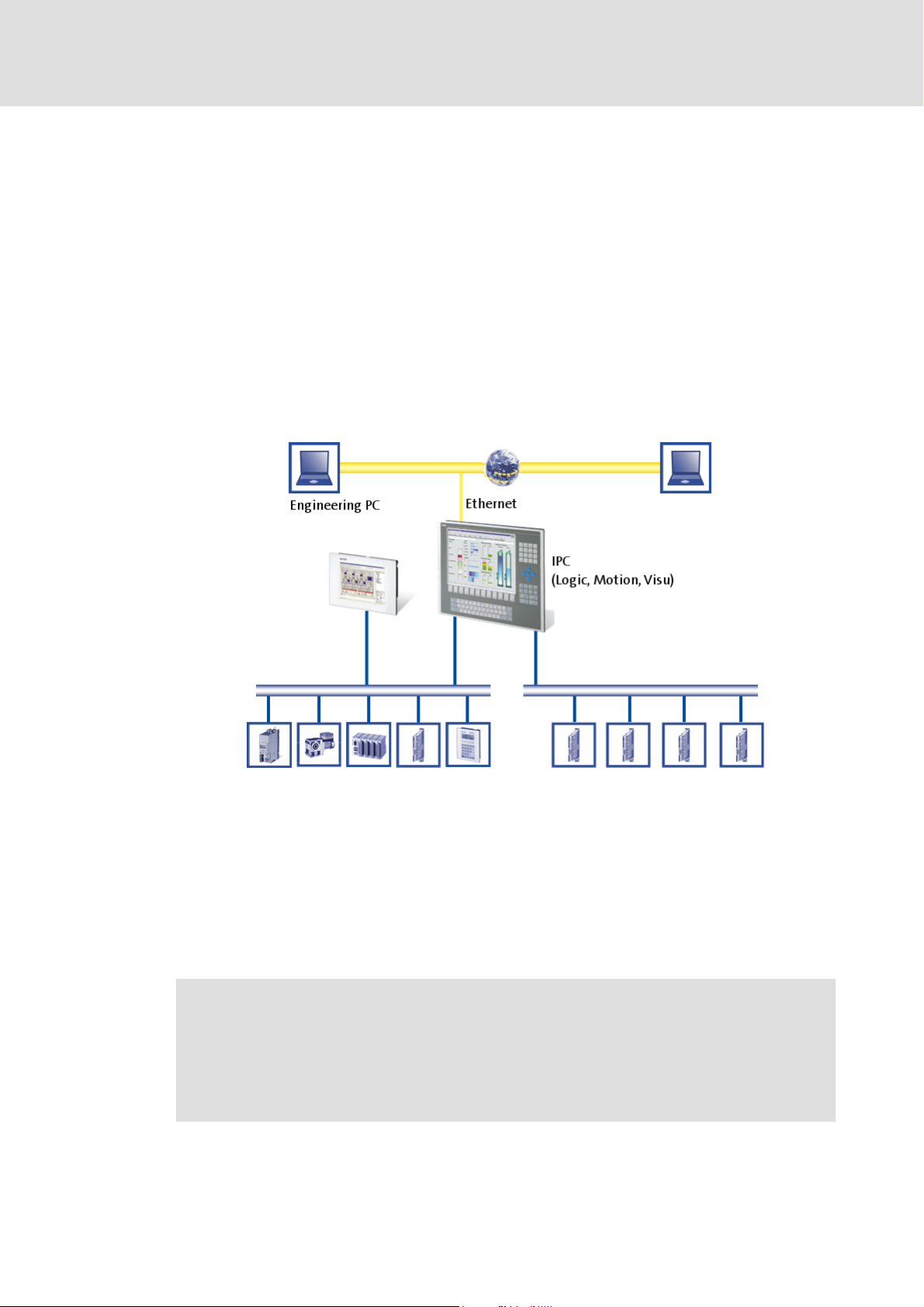
The "PC-based automation" system enables the central control of logic and motion
systems.
For this purpose, Lenze provides coordinated system components:
Industrial PCs as control and visualisation system
– The IPC is the central component of the PC-based automation which controls the
logic and motion functionalities by means of the runtime software.
– The IPC communicates with the field devices via the fieldbus.
– The IPCs are available in different designs.
Note!
Moreover, the HMI series Z EL 1xx PLC belongs to the "PC-based Automation"
system. These devices differ considerably from the industrial PCs in performance
and various other details. However, the devices of the HMI series EL 1xx PLC are
able to fulfil smaller control functions.
12 L DMS 2.2 EN 07/2011 TD17
Page 13

Control technology | PROFIBUS communication manual
The "PC-based automation" system
Engineering tools for the engineering PC
– The engineering PC communicates with the IPC via Ethernet.
– Different engineering tools
Fieldbuses
Field devices
( 22) serve to configure and parameterise the system.
DMS 2.2 EN 07/2011 TD17 L 13
Page 14

Control technology | PROFIBUS communication manual
The Lenze control system with PROFIBUS
Brief description of PROFIBUS
4 The Lenze control system with PROFIBUS
Note!
In the Lenze control system, only the PROFIBUS master functionality (logic bus)
is supported.
This chapter provides basic information about ...
the PROFIBUS bus system in the Lenze control system;
the structure of the Lenze control system with the PROFIBUS master;
the components required for PROFIBUS communication.
4.1 Brief description of PROFIBUS
Today, PROFIBUS is the most commonly used fieldbus system. Because it comes with the
widest range of various field devices, PROFIBUS is occasionally prioritised over more
modern bus systems. Due to the low bandwidth and synchronisation mechanisms,
PROFIBUS is only provided as logic bus within "PC-based Automation".
We recommend to use PROFIBUS for the following applications:
Control of system parts that have already been automated with PROFIBUS and another
control system.
Use of field devices that are not available for other bus systems (e.g. CANopen or
EtherCAT).
Combination of PROFIBUS as logic bus with CANopen as motion bus
( 18)
Tip!
Detailed information on PROFIBUS can be found on the internet page of the
PROFIBUS user organisation:
www.profibus.com
14 L DMS 2.2 EN 07/2011 TD17
Page 15
Control technology | PROFIBUS communication manual
4.1.1 Structure of the PROFIBUS system
Basic structure
The Lenze control system with PROFIBUS
Brief description of PROFIBUS
Physical structure
The industrial PC (IPC) is the PROFIBUS master. It can communicate with one or several
stations (slaves).
PROFIBUS has an internal line topology (without repeater) or a tree topology (with
repeater).
Basic wiring of PROFIBUS
The PROFIBUS network must be terminated at the first and last station. The bus
terminating resistor is integrated in the bus connector and is activated by a switch.
( 17)
DMS 2.2 EN 07/2011 TD17 L 15
Page 16

Control technology | PROFIBUS communication manual
The Lenze control system with PROFIBUS
Brief description of PROFIBUS
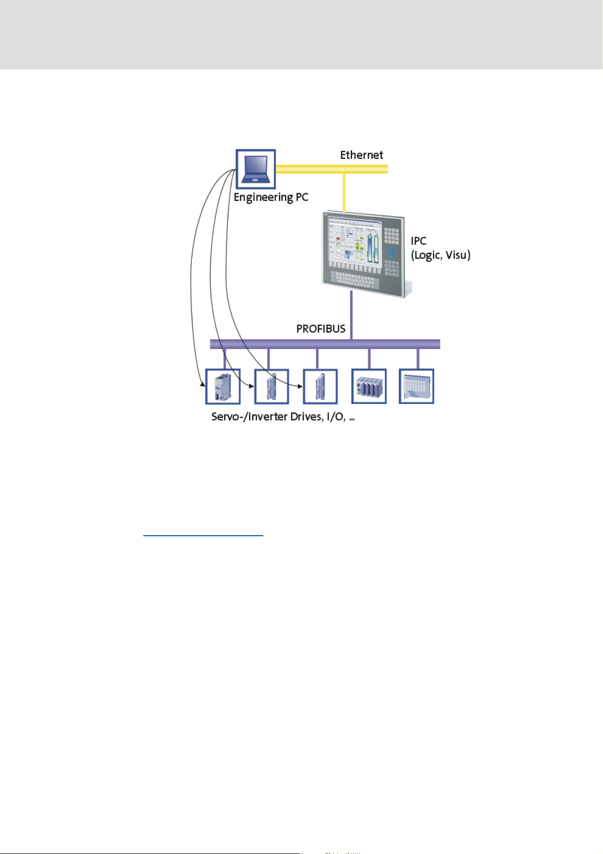
Parameter setting
The PROFIBUS stations can be parameterised in different ways:
Direct access of the engineering software (from the engineering PC) to the slave field
device. Depending on the device type, via the following interfaces:
–CAN
– Ethernet
– LECOM
– Diagnostic interface
Parameter transfer from the control (the parameter transfer must be programmed
manually)
– PROFIBUS is exclusively configured with the »PLC Designer«:
Structure of the control configuration and creation of the PLC program
– All PROFIBUS slaves can be switched on via device data base files (GSE files).
Note!
The "IPC as gateway" function is not available in connection with PROFIBUS.
Thus, "Going online" with the »Engineer« or the »GDC« via the IPC as gateway is
not possible.
16 L DMS 2.2 EN 07/2011 TD17
Page 17
Control technology | PROFIBUS communication manual
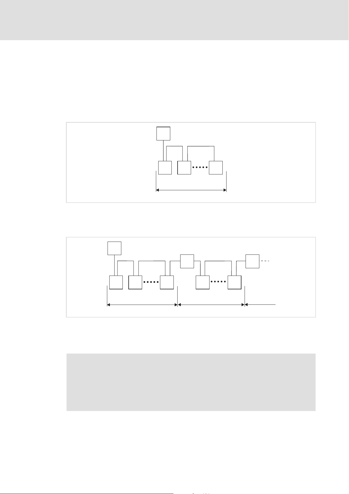
4.1.2 Basic wiring of PROFIBUS
The following examples show two simple PROFIBUS networks.
Each segment of the network must be terminated at both ends. The bus terminators of
PROFIBUS are marked with a "Z" in each of the following examples.
In a PROFIBUS network of only one segment, the PROFIBUS master (M) with an integrated
bus terminator starts the segment, and the connector of the last device (S) with the bus
terminator ends it.
The Lenze control system with PROFIBUS
Brief description of PROFIBUS
M
Z
Z
S SS
1
[4-1] PROFIBUS network with one segment
A PROFIBUS network consisting of several segments contains repeaters (R) for connecting
the segments. The repeaters are provided with integrated bus terminators.
M
Z
Z
Z
S SS
Z
R
S S
Z
R
Z
1 23
[4-2] PROFIBUS network with repeater
If no repeater is used at the end of the segment, the bus terminator in the plug of the last
device must be activated.
E94YCPM012a
E94YCPM012b
Note!
Repeaters do not have a station address. When calculating the maximum number
of stations, they reduce the number of stations by 1 on each side of the segment.
Repeaters can be used to build up line and tree topologies. The maximum total bus
system expansion depends on the baud rate used and the number of repeaters.
DMS 2.2 EN 07/2011 TD17 L 17
Page 18

Control technology | PROFIBUS communication manual
The Lenze control system with PROFIBUS
Brief description of PROFIBUS
4.1.3 Combination with other bus systems
The PROFIBUS bus system can be combined with CANopen. This makes sense if not all field
devices are available for the same bus system or a motion bus (CANopen) is required in
parallel to PROFIBUS (as logic bus). The bus systems are synchronised in the control system.
Note!
• Mixed operation is only possible with industrial PCs which have two
additional slots for communication cards. Mixed operation is not possible
with the "Command Station".
• In release 2.5, PROFIBUS cannot be combined with EtherCAT.
• In the control configuration the PROFIBUS master must be arranged in the
first position – in front of the CANopen motion stations.
4.1.4 Field devices
The Lenze control system supports the following logic components for PROFIBUS:
Standard devices PROFIBUS communication cards/modules
Industrial PCs EL x1xx PLC MC-PBM (PROFIBUS master)
EL x8xx
CS x8xx
Servo Drives 9400 HighLine E94AYCPM
Inverter Drives 8400 BaseLine E84AYCPM
I/O system IP20 EPM-T120
I/O system 1000 EPM-S120 (in preparation)
Frequency inverter 8200 vector E82ZAFPCxxx
ECS servo system ECSxE EMF2133IB
CPC x8xx
PLC
StateLine
HighLine
TopLine
EPM-T121
ECSXS (Speed & Torque)
ECSxP (Posi & Shaft)
ECSxA (Application)
18 L DMS 2.2 EN 07/2011 TD17
Page 19
Control technology | PROFIBUS communication manual
4.2 PROFIBUS hardware for the industrial PC
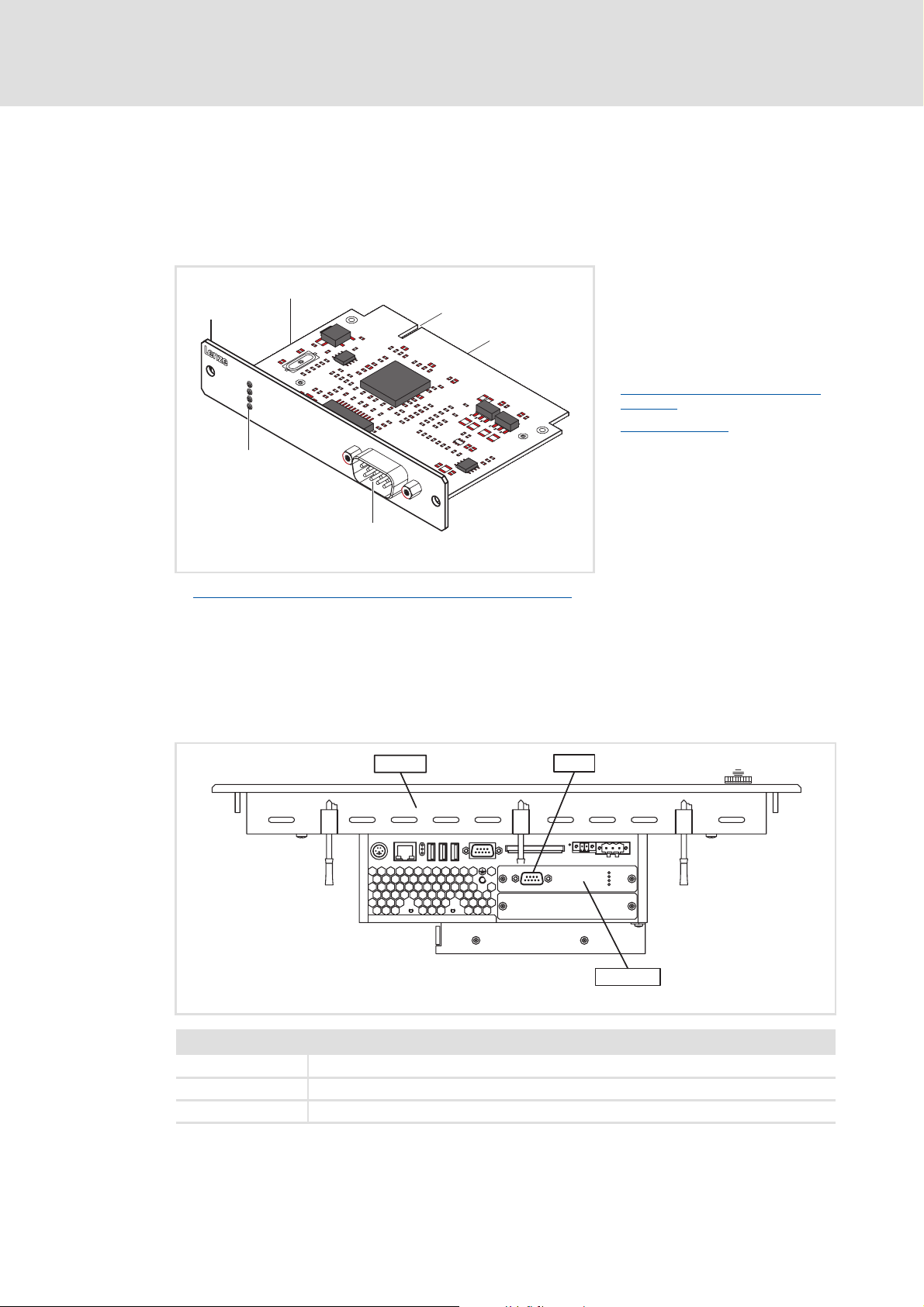
MC-PBM communication card
The MC-PBM communication card is a plug-in card for connecting an industrial PC as
PROFIBUS master to a PROFIBUS network.
The Lenze control system with PROFIBUS
PROFIBUS hardware for the industrial PC
0
MC-PNx
1
2
3
SYS
ST0
ST1
ST2
PROFIBUS
A Front panel
B Printed circuit board
C Coding
D Terminal for industrial PC
E Connection of PROFIBUS (SUB-D, 9-
pole plug) ( 20)
F LED status displays
( 63)
5
4
MC_PBx_001
Technical data of the MC-PBM communication card
Possible applications
The MC-PBM communication card can be plugged into slot 1 and slot 2 of the industrial PC.
Several PROFIBUS communication cards can be used for each industrial PC.
Example: Industrial PC EL x8xx with MC-PBM in slot 1
( 20)
EL x8xx
Legend
EL x8xx Industrial PC of the EL x8xx series
PBM1 PROFIBUS connection
MC-PBM PROFIBUS master communication card
PBM1
l
l
MC-PBM
MC-PBM_ELx8xx
DMS 2.2 EN 07/2011 TD17 L 19
Page 20
Control technology | PROFIBUS communication manual
Technical data
Technical data of the MC-PBM communication card
5 Technical data
5.1 Technical data of the MC-PBM communication card
Field Values
Protocol PROFIBUS-DP (V0, V1), ISO 7498
Communication medium RS485
Network topology Line terminated on both sides (without repeater) / tree (with
repeater)
• Termination with Sub-D plug
Type within the network Master
Max. number of stations per segment 63
Max. number of stations per network 128
Baud rate See chapter "Baud rate / bus cable length
Bus length
Connection SUB-D, 9-pole plug
" ( 21)
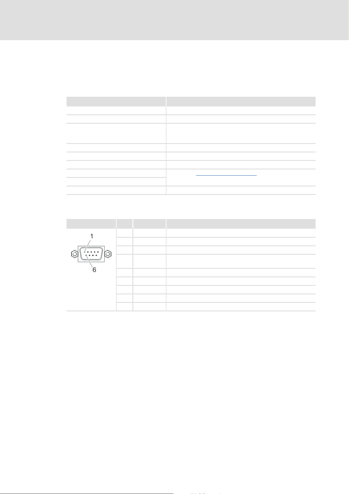
Connection of PROFIBUS (SUB-D, 9-pole plug)
View Pin Assignment Description
1free -
2free -
3 RxD/TxD-P Data line B (received data/transmitted data plus)
4 RTS Request To Send (received data / transmitted data, no differential
signal)
5 M5V2 Data ground (ground to 5 V)
6 P5V2 5 V DC / 30 mA (bus termination)
7free -
8 RxD/TxD-N Data line A (received data / transmitted data minus)
9free -
20 L DMS 2.2 EN 07/2011 TD17
Page 21

Control technology | PROFIBUS communication manual
5.2 Bus cable specification
Please follow the specifications of the PROFIBUS user organisation for bus cables.
Field Values
Cable resistance 135 ... 165 Ω/km, (f = 3 ... 20 MHz)
Capacitance per unit length ≤ 30 nF/km
Loop resistance < 110 Ω/km
Core diameter > 0.64 mm
Core cross-section > 0.34 mm
Cores Twisted in pairs, insulated and shielded
Baud rate / bus cable length
Adapt the baud rate to the length of the bus cable.
Baud rate [kbps] Max. bus length [m]
9.6 ... 93.75 1200
187.5 1000
500 200
1500 200
3000 ... 12000 100
Technical data
Bus cable specification
2
Note!
The baud rate depending of the data volume, cycle time, and number of stations
should only be selected as high as required for the application.
DMS 2.2 EN 07/2011 TD17 L 21
Page 22

Control technology | PROFIBUS communication manual
Commissioning of PROFIBUS
Overview of the commissioning steps
6 Commissioning of PROFIBUS
This chapter provides information about how to commission the Lenze control system
with PROFIBUS.
Depending on the field devices used, the following Lenze engineering tools are required:
»PLC Designer«
»Engineer«
»Global Drive Control« (GDC)
Tip!
For using other fieldbus systems, you may require further engineering software.
More information can be found in the corresponding communication manuals.
6.1 Overview of the commissioning steps
The main commissioning steps are listed in the following table:
Step Action Software to be used
1. Planning the bus topology
2. Installing field devices
3. Creating a project folder
4. Storing the device data base files (GSE)
5. Commissioning of field devices
6. Creating a PLC program
7. Configuring the PROFIBUS master
8. Configuring the PROFIBUS slave ( 33) »PLC Designer«
9. Compiling project data
10. Logging on to the control system with the »PLC Designer«
11. Loading and starting the PLC program ( 36) »PLC Designer«
( 23)
( 23)
( 24)
( 26) »PLC Designer«
( 36) »PLC Designer«
( 24)
( 25) »Engineer«
»GDC«
( 29) »PLC Designer«
( 36) »PLC Designer«
22 L DMS 2.2 EN 07/2011 TD17
Page 23

Control technology | PROFIBUS communication manual
6.2 Detailed commissioning steps
The individual commissioning steps are described in the following sections.
Follow the instructions step by step to commission your system.
More detailed information about how to work with the Lenze engineering tools
can be found in the corresponding manuals and online helps.
6.2.1 Planning the bus topology
Before you start to set up a PROFIBUS network, first create a plan of your network.
Note!
Observe the connection between the bus cable length and baud rate.
Commissioning of PROFIBUS
Detailed commissioning steps
Baud rate / bus cable length
How to plan the bus topology for your configuration:
1. Create an overview screen of the planned PROFIBUS network with all field devices
to be implemented.
2. Start with the industrial PC (master).
3. Add the other field devices (slaves) below.
6.2.2 Installing field devices
For the installation of a field device, follow the mounting instructions for the respective
device.
Activation of the bus terminating resistor
The PROFIBUS network must be terminated at the first and last station. The bus
terminating resistor is integrated in the bus connector and is activated by a switch.
Note!
( 21)
If you want to disconnect individual bus stations, ensure that the bus
terminators at the cable ends remain active.
The bus termination is not active anymore if e.g. in the event of service the plug
has been removed or the module supply has been switched off.
DMS 2.2 EN 07/2011 TD17 L 23
Page 24

Control technology | PROFIBUS communication manual
Commissioning of PROFIBUS
Detailed commissioning steps
6.2.3 Creating a project folder
Create a project folder on the engineering PC.
Use this project folder to store the below data generated in the different project
configuration steps:
Project data created in the »Engineer« or »GDC«
The project file created in the »PLC Designer«
Project data of other engineering tools
Tip!
Create a separate project folder for every PROFIBUS configuration for storing the
project files.
6.2.4 Storing the device data base files (GSE)
The data of the bus pheripherals required for the master control are stored in a GSE file.
This file is required for programming the control.
Current GSE files (e.g. for the I/O system IP20 or for Lenze PROFIBUS communication
modules) can be downloaded in the Download area at http://www.Lenze.com
Store the required GSE files in the »PLC Designer« target directory:
C:\...\Lenze\PlcDesigner\Targets\L-force_Logic_x800_V8\PlcConfPCMatic
C:\...\Lenze\PlcDesigner\Targets\L-force_Motion_x800_V8\PlcConfPCMaticMotion
Note!
PROFIBUS can be used in motion and logic systems. In the Lenze control system,
PROFIBUS is the logic bus. Only use PROFIBUS in a motion system if an additional
motion bus (e.g. CAN) is used.
CANopen with PROFIBUS
Tip!
The GSE files can also be stored via the »PLC Designer« with the menu command
ExtrasAdd configuration file.
.
( 37)
24 L DMS 2.2 EN 07/2011 TD17
Page 25

Control technology | PROFIBUS communication manual
6.2.5 Commissioning of field devices
Parameterise the Lenze field devices connected to PROFIBUS either with the »Engineer« or
with »GDC«, depending on the device.
PROFIBUS is exclusively configured with the »PLC Designer«.
Observe the information with regard to commissioning in the documentation
for the field devices.
Tip!
We recommend to commission each field device individually and then integrate
them into the PLC program.
Servo Drives 9400 HighLine
Commissioning of PROFIBUS
Detailed commissioning steps
During commissioning of a Servo Drive 9400 HighLine, the module parameter
DeactivateDPV1AutoSet must be set to the value "No":
DMS 2.2 EN 07/2011 TD17 L 25
Page 26

Control technology | PROFIBUS communication manual
Commissioning of PROFIBUS
Detailed commissioning steps
6.2.6 Configuration in the »PLC Designer«
The »PLC Designer« serves to map the field device topology in the control configuration.
Tip!
The »PLC Designer« serves to configure PROFIBUS stations and nodes on other
fieldbus systems.
CANopen with PROFIBUS
6.2.6.1 Creating a PLC program
How to create a PLC program in the »PLC Designer«:
1. Create a new »PLC Designer« project:
• Menu command: FileNew
2. Select the suitable target system from the Target Settings dialog box:
Target system Use with IPC series
L-force Logic x800 V8.xx.xx zzz -
L-force Logic EL1xx V1.xx ---z
( 37)
EL x8xx CS x8xx CPC x8xx EL 1xx PLC
The target systems of release 2.2/2.3 (L-force Logic x700) can also be used for
device series EL x8xx, CS x8xx, and CPC x8xx.
3. Confirm the configuration of the target system setting by clicking the OK button.
26 L DMS 2.2 EN 07/2011 TD17
Page 27

4. Create a block:
Note!
The block must contain at least one instruction to function properly.
Control technology | PROFIBUS communication manual
Commissioning of PROFIBUS
Detailed commissioning steps
DMS 2.2 EN 07/2011 TD17 L 27
Page 28

Control technology | PROFIBUS communication manual
Commissioning of PROFIBUS
Detailed commissioning steps
5. Create the control configuration:
•Open the Resources dialog box:
•Open the PLC Configuration dialog box:
Setting Description
Automatic calculation of addresses Every newly added module automatically gets an address which results from
Check for overlapping addresses During the compilation of the project, a check for address overlapping is
Save configuration files in project The data of the configuration file(s) *.cfg and device files on which the
the address of the module integrated before and the size of this module. If a
module is removed from the configuration, the addresses of the subsequent
modules are adapted automatically.
The ExtrasCalculate addresses menu command serves to recalculate the
addresses starting with the currently selected node (module).
carried out and overlapping addresses are indicated.
current control configuration is based are stored in the project.
Note!
We recommend to keep the standard setting. In the case of a manual address
allocation, you must ensure that each object address is non-ambiguous in the
entire control configuration.
Detailed information on this can be found in the documentation/online help of
the »PLC Designer«.
28 L DMS 2.2 EN 07/2011 TD17
Page 29

Control technology | PROFIBUS communication manual
6.2.6.2 Configuring the PROFIBUS master
How to configure the PROFIBUS master:
1. Add the bus interface to the PLC configuration:
The "ProfibusMaster" subelement represents the PROFIBUS interface of the IPC to
which the logic bus is connected.
Commissioning of PROFIBUS
Detailed commissioning steps
2. Set DP parameters for the PROFIBUS master:
• The standard setting of the PROFIBUS master station address is ’1’. Only change
the setting if the address is to deviate from ’1’.
• The "highest station address" is incremented automatically with each added
slave. Thus the value should not be changed manually.
•The GSE file... button serves to open and inspect the device-related GSE file.
•The Groups... button leads to the Group properties dialog. The group properties
refer to the slaves assigned to the master.
DMS 2.2 EN 07/2011 TD17 L 29
Page 30

Control technology | PROFIBUS communication manual
Commissioning of PROFIBUS
Detailed commissioning steps
Up to eight groups can be arranged. Set for each group whether they are to be
operated in freeze mode and/or sync mode. By assigning the slaves (see "Properties
of the DP slave", "Group assignment") to different groups, the data exchange from
the master via a global control command can be synchronised.
A freeze command causes a master, a slave, or a group, to "freeze" the input in the
current status and transfer these data in the next data exchange process.
A sync command causes the slaves to connect the data received by the master
through to the outputs synchronously regarding time with the next sync
command.
In order to switch on/off the freeze and sync option for one group, left-click the
corresponding position in the table to place/remove an 'X' at the requested option
or right-click it to activate/deactivate the option via a context menu. Moreover you
can edit the group names here.
30 L DMS 2.2 EN 07/2011 TD17
Page 31

Control technology | PROFIBUS communication manual
Commissioning of PROFIBUS
Detailed commissioning steps
3. Go to the Bus parameters tab to set the baud rate for PROFIBUS:
4. Go to the Module parameters tab to set the "Byteorder wordmodules motorola"
parameter:
The "Byteorder wordmodules motorola" parameter determines how the data are
copied from PROFIBUS to the process image.
Setting Description
No Standard setting:
The data are received by the bus in Motorola format (Big Endian) and copied into the Intel format
(Little Endian). The user sees a correct integer value (INT) (example: ’0x1234’ ’0x1234’).
We recommend to keep this setting. Like this, the slave data are correctly transferred to the
process image.
Yes The data are copied without being transposed from the bus to the process image. The user sees
a transposed integer value (INT) (example: ’0x1234’ ’0x3412’).
• Compatibility with other projects from the version 1.5
DMS 2.2 EN 07/2011 TD17 L 31
Page 32

Control technology | PROFIBUS communication manual
Commissioning of PROFIBUS
Detailed commissioning steps
5. Attach PROFIBUS slave:
The GSE file of the PROFIBUS slave must be stored in the »PLC Designer« target
directory.
Storing the device data base files (GSE)
( 24)
32 L DMS 2.2 EN 07/2011 TD17
Page 33

Control technology | PROFIBUS communication manual
6.2.6.3 Configuring the PROFIBUS slave
How to configure the PROFIBUS slave:
1. Set DP parameters for the PROFIBUS slave:
Commissioning of PROFIBUS
Detailed commissioning steps
• Enter the station address of the PROFIBUS slave here.
• A baud rate does not need to be set since the slave recognises the baud rate
automatically.
•The GSE file... button serves to open and inspect the device-related GSE file.
DMS 2.2 EN 07/2011 TD17 L 33
Page 34

Control technology | PROFIBUS communication manual
Commissioning of PROFIBUS
Detailed commissioning steps
2. Via the Input/Output tab, configure the input and output objects for the slaves.
Note!
The input and output objects must be configured in the same sequence as they
are arranged physically at the bus.
• In the left window, the dialog lists all input and output modules, process data
objects (PCD) and DRIVECOM parameter objects (e.g. for Servo Drives 9400)
which are available in the GSE file of the slave.
• The right window contains the configuration of the inputs and outputs
currently selected for this device.
• This type of selection is not possible with non-modular slaves. These cause a
closed representation of their inputs and outputs in the right window.
•The Properties button leads to the Module properties dialog of the input or
output object currently selected in the left or right list.
34 L DMS 2.2 EN 07/2011 TD17
Page 35

Control technology | PROFIBUS communication manual
Commissioning of PROFIBUS
Detailed commissioning steps
3. Assign for each address of the input and output objects (e.g. %IB0, %QB0, ...) a
symbolic name which is non-ambiguous in the entire control configuration in
accordance with the IEC 61131 syntax (no blanks and leading digits in the variable
name):
• Symbolic names can be entered by a mouse-click in front of ’AT %... ;’.
Note!
When symbolic names are entered, corresponding system variables are created
for the PLC program.
Always use the system variables within the PLC program in order to access the
input and output objects or assign values to them.
The <F2> function key serves to open the input assistance in the »PLC Designer«.
DMS 2.2 EN 07/2011 TD17 L 35
Page 36

Control technology | PROFIBUS communication manual
Commissioning of PROFIBUS
Detailed commissioning steps
6.2.6.4 Compiling project data
To compile the project data, select the ProjectBuild menu command or press the <F11>
function key.
If errors occurred during the compilation process, you can locate and eliminate them by
means of the »PLC Designer« error messages. Then compile the project data again.
If no errors occurred during the compilation process, save the »PLC Designer« project to
the project folder.
6.2.6.5 Logging on to the control system with the »PLC Designer«
To log the »PLC Designer« on to the control system, select the menu command
OnlineLogin.
For this, the PLC program must be error-free.
Confirm the appearing query dialog whether the new program is to be loaded with Yes.
6.2.6.6 Loading and starting the PLC program
How to load and start the PLC program on the IPC:
1. Select the OnlineDownload menu command.
2. Select the required file in the appearing dialog window.
3. Confirm the selection by clicking the Open button.
• The file is loaded onto the IPC and saved there under the same name.
• The PROFIBUS is initialised.
4. Select the OnlineRun menu command.
• The PLC program is executed.
• The cyclic data transfer starts.
Note!
• The bus starts even if not all stations at the bus are available.
• When the PLC program is stopped, (menu command OnlineStop) the cyclic
data transfer continues to run until a reset source is executed (Menu
command OnlineReset (original)).
Tip!
The menu command OnlineRead file from PLC can be used to reload a file from
the IPC into the »PLC Designer« project.
36 L DMS 2.2 EN 07/2011 TD17
Page 37

Control technology | PROFIBUS communication manual
7 CANopen with PROFIBUS
The PROFIBUS bus system can be combined with CANopen. This makes sense if not all field
devices are available for the same bus system or a motion bus (CANopen) is required in
parallel to PROFIBUS (as logic bus). The bus systems are synchronised in the control system.
Note!
• Mixed operation is only possible with industrial PCs which have two
additional slots for communcation cards. Mixed operation is not possible
with the "Command Station".
• In release 2.5, PROFIBUS cannot be combined with EtherCAT.
• In the control configuration the PROFIBUS master must be arranged in the
first position – in front of the CANopen motion stations.
CANopen with PROFIBUS
"CANopen control technology" communication manual
Here you can find detailed information on how to commission CANopen
components.
Addressing the CANopen and PROFIBUS stations
The addresses for input and output objects of the PROFIBUS and CANopen stations are
automatically allocated in the »PLC Designer« (standard setting):
Note!
We recommend to keep the standard setting. In the case of a manual address
allocation, you must ensure that each object address is non-ambiguous in the
entire control configuration.
Detailed information on this can be found in the documentation of the »PLC
Designer«.
DMS 2.2 EN 07/2011 TD17 L 37
Page 38

Control technology | PROFIBUS communication manual
Function libraries
8 Function libraries
For configuring PROFIBUS and for diagnostic purposes, the following function libraries are
available in the »PLC Designer«:
Function libraries Application
BusDiag.lib function library
NetXPBInfo.lib function library
HilscherNetX.lib function library
SysLibDPV1Hilscher.lib function library
( 39) This library serves to query diagnostics information from
the PROFIBUS master and the slaves.
( 44) This library serves to query various information of the
PROFIBUS master (e.g. error counter, bus cycle counter).
( 46) This library enables direct access to the package interface
of the PROFIBUS communication card.
( 50) This library supports the acyclic PROFIBUS DPV1 - class 1
write and read services for data transfer between the
master and the slaves. (For this see PROFIBUS-DP
standard.)
More information on the function libraries can be found in the documentation/
online help of the »PLC Designer«.
38 L DMS 2.2 EN 07/2011 TD17
Page 39

Control technology | PROFIBUS communication manual
8.1 BusDiag.lib function library
The BusDiag.lib function library contains the following function blocks for diagnostics:
Function libraries
BusDiag.lib function library
DiagGetBusState function block
DiagGetState function block ( 41)
8.1.1 DiagGetBusState function block
This block serves to display the current bus status.
DiagGetBusState must be set via AT %MByy to the diagnostics address of the PROFIBUS
station to be diagnosed. The status is updated in the background. Thus, the input variables
(VAR_INPUT) do not need to be pre-assigned.
( 39)
DMS 2.2 EN 07/2011 TD17 L 39
Page 40

Control technology | PROFIBUS communication manual
Function libraries
BusDiag.lib function library
Inputs (VAR_INPUT)
The status is updated in the background. Thus, the input variables do not need to be preassigned.
Identifier/data type Meaning/possible settings
ENABLE
DRIVERNAME
POINTER TO
STRING
DEVICENUMBER
The function block is activated in an edge-controlled manner:
BOOL
• Positive edge (TRUE) = diagnostics information is detected and READY is set to
TRUE.
Name of the driver (address of the name) to which the diagnostics order is to be
transmitted.
• If a ’0’ is entered here, the diagnostics order is passed to all available drivers.
Identification of the bus which is managed by this module (driver).
INT
• The instance results from the PLC configuration. The first node attached
corresponds to instance 0, the second one to the instance 1 and so on.
• For a second MC-PBM communication card, you must create a second
GetBusState instance with another %MByy address. In order to obtain the
extended diagnostics with the DiagGetState function block
the block with Instance := 1.
( 41), you must call
Outputs (VAR_OUTPUT)
Identifier/data type Meaning/possible settings
READY
STATE
EXTENDEDINFO
ARRAY [0...129]
OF BYTE
Always TRUE: Processing of the diagnostics order is completed.
BOOL
When READY = TRUE, STATE indicates the current status of the block by one of the
following values. These values are assigned to global constants. The constants are
INT
stored in the BusDiag.lib function library.
Value = 1 The bus is ok, no error.
• Constant BUSSTATE_BUSOK
Value = 2 A bus error has occurred.
• Constant BUSSTATE_BUSFAULT
Value = 3 There is no PROFIBUS communication or communication has been
Value = 4 The PROFIBUS is set to STOPPED.
1:1 relation between the ARRAY index and the station number of the slave.
Only the first three bits of the byte are used:
aborted.
• Constant BUSSTATE_BUSNOTCOMMUNICATING
• Constant BUSSTATE_BUSSTOPPED
Bit 0 The PROFIBUS station is configured.
Bit 1 The PROFIBUS station is active at the bus.
Bit 2 The PROFIBUS station sends an error message.
• Detailed information can be obtained via the DiagGetState
function block ( 41).
Note!
After the bus is activated, the slaves set the Error-Flag (bit 2) so that the master
first reads out the diagnostics information. If the diagnostics information for the
corresponding slave is read out via the DiagGetState function block
Error-Flag is reset.
40 L DMS 2.2 EN 07/2011 TD17
( 41), the
Page 41

Control technology | PROFIBUS communication manual
8.1.2 DiagGetState function block
If a station available on the bus reports an error, its specific diagnostics information can be
read with the DiagGetState block.
DiagGetState must be called explicitly with the device number and the bus member ID
(station address).
Inputs (VAR_INPUT)
Identifier/data type Meaning/possible settings
ENABLE
DRIVERNAME
POINTER TO
STRING
DEVICENUMBER
BUSMEMBERID
DWORD
The function block is activated in an edge-controlled manner:
BOOL
• Positive edge (TRUE) = diagnostics information is detected and READY is set to
TRUE.
Always set to ’0’: The diagnostics order is passed to all available drivers.
Identification of the bus which is managed by this module (driver).
INT
• The instance results from the PLC configuration. The first PROFIBUS station
attached corresponds to the instance 0, the second to the instance 1 etc.
• For a second MC-PBM communication card, for instance, there is a second
GetBusState instance with another %MByy address. In order to obtain extended
diagnostics with the DiagGetState function block
with Instance := 1.
Station address of the PROFIBUS station for which the diagnostics information is to
be requested.
Function libraries
BusDiag.lib function library
( 41), you must call the block
Outputs (VAR_OUTPUT)
Identifier/data type Meaning/possible settings
READY
STATE
FALSE: The diagnostics order is processed.
BOOL
TRUE: Processing of the diagnostics order is completed.
When READY = TRUE, STATE indicates the current status of the block by one of the
following values. These values are assigned to global constants. The constants are
INT
stored in the BusDiag.lib function library.
Value = -1 Invalid input parameter
• Constant NDSTATE_INVALID_INPUTPARAM
Value = 0 Diagnostics information is not released.
• Constant NDSTATE_NOTENABLED
Value = 1 Diagnostics information is requested.
• Constant NDSTATE_GETDIAG_INFO
Value = 2 Diagnostics information is available.
• Constant NDSTATE_DIAGINFO_AVAILABLE
Value = 3 No diagnostics information available (error when reading data).
• Constant NDSTATE_DIAGINFO_NOTAVAILABLE
DMS 2.2 EN 07/2011 TD17 L 41
Page 42

Control technology | PROFIBUS communication manual
Function libraries
BusDiag.lib function library
Identifier/data type Meaning/possible settings
EXTENDEDINFO
ARRAY [0...129]
OF BYTE
Example: Diagnostics information of Servo Drives 9400 in ’EXTENDEDINFO’
Contains the slave-specific diagnostics information.
Byte 0 Station status 1
Byte 1 Station status 2
Byte 2 Station status 3
Byte 3 Master station number
Byte 4 Manufacturer's identification mark (high byte)
Byte 5 Manufacturer's identification mark (low byte)
Byte 6 ... n Slave-specific diagnostics information (see documentation of the
slave)
Byte in
EXTENDEDINFO
6 Bit 0: Station does not exist (set by the master).
7 Bit 0: Slave has to be parameterised again.
8 Bit 7: Diagnostics overflow - amount of diagnostics data present in the slave is too large to fit
9 Bits 0 ... 7: Master address after parameter setting ("0xFF" without parameterisation)
10 Bits 0 ... 7: ID number (high byte)
11 Bits 0 ... 7: ID number (low byte)
12 Header
13 Status_Type
14 Slot_Number
15 Specifier
16 PROFIsafe, error number of the safety module
17
Meaning
Bit 1: Slave is not ready for data exchange.
Bit 2: Configuration data do not match each other.
Bit 3: Slave has extended diagnostic data.
Bit 4: Requested service is not supported by the slave.
Bit 5: Slave response is invalid (set by the master)
Bit 6: Incorrect parameter setting
Bit 7: Slave is parameterised by another master (set by the master).
Bit 1: Static diagnostics
Bit 2: Fixedly set to "1".
Bit 3: Watchdog active
Bit 4: Freeze command received.
Bit 5: Sync command received.
Bit 6: Reserved
Bit 7: Slave is deactivated (set by the master).
into one telegram.
• The header contains the block length of extended diagnostics and the header byte.
• In this case, the value of the entry is "0x0A" (bytes 6 ... 15 = 10 bytes).
• The value of this entry is fixed. For the following bit assignment it is "0x81":
–Bit 7 = 1: "status"
–Bit 0 = 1: "status message"
–Values of all other bits = 0
• Value of the slot number: "0x00"
• A detected error is entered in the specifier with the identification "0x0" (status coming).
• An eliminated error is entered in the specifier with the identification "0x02" (status going).
• If no errors are indicated, the entry in the specifier has the value "0x00" (no further
differentiation).
• If an error occurs in the safety module, byte 10 (low byte) and byte 11 (high byte) contain the
corresponding error number.
• More information can be found in the documentation of the corresponding safety module.
42 L DMS 2.2 EN 07/2011 TD17
Page 43

Control technology | PROFIBUS communication manual
Function libraries
BusDiag.lib function library
Byte in
EXTENDEDINFO
18 ... 21 Error code of the PROFIBUS station
Meaning
• More information can be found in the documentation of the corresponding PROFIBUS
station.
DMS 2.2 EN 07/2011 TD17 L 43
Page 44

Control technology | PROFIBUS communication manual
Function libraries
NetXPBInfo.lib function library
8.2 NetXPBInfo.lib function library
The NetXPBInfo.lib function library serves to query various information on the PROFIBUS
master (e.g. error counter, bus cycle counter).
8.2.1 Structure of NETXGETPBINFOSTYP
TYPE NETXGETPBINFOSTYP :
STRUCT
iDev : INT;
iDummy : INT;
ulLastCycleTime : DWORD;
ulCycleStarts : DWORD;
ulCycleEnds : DWORD;
usBus_error_cnt : WORD;
usMsg_Timeout : WORD;
usRX_Overflow : WORD;
usBus_Off_cnt : WORD;
ucErrNumber : BYTE;
ucErrStationAdr: BYTE;
END_STRUCT
END_TYPE
Description of the components
Identifier/data type Meaning/possible settings
iDev
iDummy
ulLastCycleTime
DWORD
ulCycleStarts
DWORD
ulCycleEnds
DWORD
usBus_error_cnt
WORD
usMsg_Timeout
WORD
usRX_Overflow
WORD
usBus_Off_cnt
WORD
ucErrNumber
POINTER TO
ucErrStationAdr
POINTER TO
Device number of the PROFIBUS master
INT
Not used
INT
The time measured last to start the bus cycle.
Number of the bus cycles started
Number of the bus cycles completed
Number of the bus error events
Number of the bus message errors
Number of the transmit overflow events
Number of the Bus_OFF events
General error counter
BYTE
Last faulty slave address
BYTE
44 L DMS 2.2 EN 07/2011 TD17
Page 45

Control technology | PROFIBUS communication manual
8.2.2 NetXGetPBInfos function
This function serves to request various information on the NetX PROFIBUS master. The
information is entered into the memory transferred. The return value contains the error
code. ’0’ indicates an error, a value unequal ’0’ indicates a successful query.
Inputs (VAR_INPUT)
Identifier/data type Meaning/possible settings
pAddress
POINTER TO
NETXGETPBINFOSTYP
Function libraries
NetXPBInfo.lib function library
Pointer to an instance of the NETXGETPBINFOSTYP structure. The data are entered
into this structure.
DMS 2.2 EN 07/2011 TD17 L 45
Page 46

Control technology | PROFIBUS communication manual
Function libraries
HilscherNetX.lib function library
8.3 HilscherNetX.lib function library
The HilscherNetX.lib function library enables direct access to the package interface of the
PROFIBUS communication card.
In order to use the functions of the library, you must be provided with the
corresponding documentation of the respective NetX Hilscher firmware. The
documentation can be procured from the Lenze service.
8.3.1 CIFX_PACKET structure
TYPE CIFX_PACKET
STRUCT
tHeader : CIFX_PACKET_HEADER;
abData : ARRAY [0..1559] OF BYTE;
END_STRUCT
END_TYPE
Description of the components
Identifier/data type Meaning/possible settings
tHeader
POINTER TO
CIFX_PACKET_HEADER
abData
ARRAY [0...1559]
OF BYTE
Command and management data of the package.
Data to be sent or received
46 L DMS 2.2 EN 07/2011 TD17
Page 47

Control technology | PROFIBUS communication manual
8.3.2 CIFX_PACKET_HEADER structure
TYPE CIFX_PACKET_HEADER :
STRUCT
ulDest : UDINT;
ulSrc : UDINT;
ulDestId : UDINT;
ulSrcId : UDINT;
ulLen : UDINT;
ulId : UDINT;
ulState : UDINT;
ulCmd : UDINT;
ulExt : UDINT;
ulRout : UDINT;
END_STRUCT
END_TYPE
Description of the components
Function libraries
HilscherNetX.lib function library
Identifier/data type Meaning/possible settings
ulDest
UDINT
ulSrc
UDINT
ulDestId
UDINT
ulSrcId
UDINT
ulLen
UDINT
ulId
UDINT
ulState
UDINT
ulCmd
UDINT
ulExt
UDINT
ulRout
UDINT
Target of the package in the process flow
Source of the package in the process flow
Target reference of the package
Source reference of the package
Length of the package without header
Identification handle of the transmitter
Status of the order
Package command
• See NetX documentation for detailed information.
Extension
• Is not used (value = ’0’)
Routing
• Is not used (value = ’0’)
DMS 2.2 EN 07/2011 TD17 L 47
Page 48

Control technology | PROFIBUS communication manual
Function libraries
HilscherNetX.lib function library
8.3.3 CIFXGetChannelHandle function
This function provides the handle of the NetX channel as return value. This handle can be
used to request the CIFXGetPacket functions and CIFXPutPacket. In the event of an error,
’0’ is returned.
Inputs (VAR_INPUT)
Identifier/data type Meaning/possible settings
iDevice
8.3.4 CIFXPutPacket function
This functions transmits a package to the NetX channel. A package of the CIFX_PACKET
type must be transmitted. When it is sent, the ulSrcId value is written by the driver. This is
important to retrieve the response to the request. The return value is the error code. ’0’
means error-free, unequal ’0’ is the error case. The Hilscher firmware documentation
describes the error codes in detail.
Device number of the NetX station
INT
Inputs (VAR_INPUT)
Identifier/data type Meaning/possible settings
hChannel
pPacket
ulTimeout
UDINT
POINTER TO
CIFX_PACKET
UDINT
Handle of the channel which can be queried via CIFXGetChannelHandle.
Pointer to the package which is to be transmitted.
Transmit time-out which is waited for.
48 L DMS 2.2 EN 07/2011 TD17
Page 49

Control technology | PROFIBUS communication manual
8.3.5 CIFXGetPacket function
This function retrieves the response to a package transmitted before. For this, the
management data of the transmitted package must be accepted unchanged. It is
important that the ulSrcId value changed by the driver is transferred. The return value is the
error code. ’0’ means error-free, unequal ’0’ is the error case. The Hilscher firmware
documentation describes the error codes in detail.
Inputs (VAR_INPUT)
Identifier/data type Meaning/possible settings
hChannel
UDINT
udiSize
UDINT
pPacket
POINTER TO
CIFX_PACKET
ulTimeout
UDINT
ulRemAddress
UDINT
Function libraries
HilscherNetX.lib function library
Handle of the channel which can be queried via CIFXGetChannelHandle.
Size of the memory area which is transferred together with pPacket.
Pointer to the package which is to be transmitted.
Receipt time-out which is waited for.
Set to ’0’.
DMS 2.2 EN 07/2011 TD17 L 49
Page 50

Control technology | PROFIBUS communication manual
Function libraries
SysLibDPV1Hilscher.lib function library
8.4 SysLibDPV1Hilscher.lib function library
The SysLibDPV1Hilscher.lib function library supports the acyclic PROFIBUS DPV1 - class 1
write and read services for data transfer between the master and the slaves. The data is
addressed within the slave stations via slot and index (for this see the PROFIBUS-DP
standard).
If the target system is supported, the following function blocks are available:
DPV1_Read / DPV1_ReadEx function block
DPV1_Write / DPV1_WriteEx function block ( 52)
8.4.1 V1State structure
This structure is used by the blocks of the SysLibDPV1Hilscher.lib library with the State
output variable. It describes the status of the order.
TYPE V1State :
(NotEnabled := 0, InvalidParam, Started, Done, DoneWithError );
END_TYPE
Description of the components
Identifier/data type Meaning/possible settings
NotEnabled := 0 The function block is not active.
InvalidParam Invalid input parameter
Started The function block has started processing.
Done The function block has completed processing.
( 51)
DoneWithError The function block has aborted processing with an error.
50 L DMS 2.2 EN 07/2011 TD17
Page 51

Control technology | PROFIBUS communication manual
8.4.2 DPV1_Read / DPV1_ReadEx function block
This function block serves to read data.
Inputs (VAR_INPUT)
Identifier/data type Meaning/possible settings
ENABLE
Device
StationAddr
Slot
Index
Len
buffer
DWORD
The function block is activated in an edge-controlled manner:
BOOL
• Positive edge (TRUE) = diagnostics information is detected and READY is set to
TRUE.
Index of the Hilscher card to which the order is transferred.
INT
Station address of the slave in PROFIBUS.
INT
Data slot for identifying the data in the slave.
INT
Data index for identifying the data in the slave.
INT
Length of the data to be read/written in bytes.
INT
• Here, the maximum length of the buffer data buffer is transferred.
The local address of the data (created with ADR()).
Function libraries
SysLibDPV1Hilscher.lib function library
Outputs (VAR_OUTPUT)
Identifier/data type Meaning/possible settings
READY
STATE
POINTER TO
V1State
Size
Error
ARRAY [0 ... 7]
OF BYTE
FALSE: The read request is processed.
BOOL
TRUE: The read request is completed.
Information on the status of the order
• See V1State structure
Length of the actually read/written data when executed successfully.
INT
Information on errors occurred
• Only contained in DPV1_ReadEx function block.
Byte 1 Hilscher error code
• See documentation of Hilscher PROFIBUS cards "Protocol
Interface Manual Profibus DP" for detailed information.
Byte 2 Error class code
• See PROFIBUS standard for detailed information.
Byte 3 + 4 Index 2 + 3: Slave-specific error information
• See documentation of the slave for detailed information.
( 50)
DMS 2.2 EN 07/2011 TD17 L 51
Page 52

Control technology | PROFIBUS communication manual
Function libraries
SysLibDPV1Hilscher.lib function library
8.4.3 DPV1_Write / DPV1_WriteEx function block
This function block serves to write data.
Inputs (VAR_INPUT)
Identifier/data type Meaning/possible settings
ENABLE
Device
StationAddr
Slot
Index
Len
buffer
DWORD
The function block is activated in an edge-controlled manner:
BOOL
• Positive edge (TRUE) = diagnostics information is detected and READY is set to
TRUE.
Index of the Hilscher card to which the order is transferred.
INT
Station address of the slave in PROFIBUS.
INT
Data slot for identifying the data in the slave.
INT
Data index for identifying the data in the slave.
INT
Length of the data to be read/written in bytes.
INT
• Here, the maximum length of the buffer data buffer is transferred.
The local address of the data (created with ADR()).
Outputs (VAR_OUTPUT)
Identifier/data type Meaning/possible settings
READY
STATE
POINTER TO
V1State
Size
Error
ARRAY [0 ... 7]
OF BYTE
FALSE: The read request is processed.
BOOL
TRUE: The read request is completed.
Information on the status of the order
• See V1State structure
Length of the actually read/written data when executed successfully.
INT
Information on errors occurred
• Only contained in DPV1_WriteEx function block.
Byte 1 Hilscher error code
• See documentation of Hilscher PROFIBUS cards "Protocol
Interface Manual Profibus DP" for detailed information.
Byte 2 Error class code
• See PROFIBUS standard for detailed information.
Byte 3 + 4 Index 2 + 3: Slave-specific error information
• See documentation of the slave for detailed information.
( 50)
52 L DMS 2.2 EN 07/2011 TD17
Page 53

Control technology | PROFIBUS communication manual
SysLibDPV1Hilscher.lib function library
8.4.4 Telegram examples of the PROFIdrive parameter data channel (DP-V1)
In the following, a parameter read order and a parameter write order for a Servo Drive 9400
are described.
8.4.4.1 Example of read request: Query heatsink temperature
The heatsink temperature of the Servo Drive 9400 is to be read.
Code to be read: C00061
Heatsink temperature: 43 °C
Parameter request
Byte 1 Byte 2 Byte 3 Byte 4
Job reference Job identification Axis Number of indexes
0xXX 0x01 0x00 0x01
Request parameter for reading
Function libraries
Byte 5 Byte 6
Attribute Number of subindexes
0x10 0x00
Value No subindex
Byte 7 Byte 8 Byte 9 Byte 10
Index Subindex
High byte Low byte High byte Low byte
0x5F 0xC2 0x00 0x00
Index = 24575 - code no. = 24575 - 61 = 24514 = 0x5F C2 No subindex
Parameter response to a correctly executed read request
Byte 1 Byte 2 Byte 3 Byte 4
Job reference Response identification Axis Number of indexes
0xXX 0x01 0x00 0x01
(Mirrored) Parameter read (Mirrored)
Byte 5 Byte 6
Format Number of values
0x43 0x01
Double word 1 value
Byte 7 Byte 8 Byte 9 Byte 10
Value
High word: high byte High word: low byte Low word: high byte Low word: low byte
0x00 0x00 0x00 0x2B
Value read = 0x00 00 00 2B = 43 x 1 (internal factor) = 43 [°C]
DMS 2.2 EN 07/2011 TD17 L 53
Page 54

Control technology | PROFIBUS communication manual
Function libraries
SysLibDPV1Hilscher.lib function library
Parameter response to a read error
Byte 1 Byte 2 Byte 3 Byte 4
Job reference Response identification Axis Number of indexes
0xXX 0x81 0x00 0x01
(Mirrored) Parameter not read (Mirrored)
Byte 5 Byte 6
Format Number of values
0x44 0x01
Error Error code without additional
Byte 7 Byte 8
Error code
High byte Low byte
See documentation of the PROFIBUS station.
information
54 L DMS 2.2 EN 07/2011 TD17
Page 55

Control technology | PROFIBUS communication manual
SysLibDPV1Hilscher.lib function library
8.4.4.2 Example of write request: Set deceleration time for quick stop
In the Servo Drive 9400, the ramp time for quick stop is to be set to 50 ms.
Code to be written to: C00105
Parameter request
Byte 1 Byte 2 Byte 3 Byte 4
Job reference Job identification Axis Number of indexes
0xXX 0x02 0x00 0x01
Write parameter Axis 0 1 index
Byte 5 Byte 6
Attribute Number of subindexes
0x10 0x00
Value No subindex
Function libraries
Byte 7 Byte 8 Byte 9 Byte 10
Index Subindex
High byte Low byte High byte Low byte
0x5F 0x96 0x00 0x00
Index = 24575 - code no. = 24575 - 105 = 24470 = 0x5F 96 No subindex
Byte 11 Byte 12
Format Number of values
0x43 0x01
Double word 1 value
Byte 13 Byte 14 Byte 15 Byte 16
Value
High word: high byte High word: low byte Low word: high byte Low word: low byte
0x00 0x00 0x00 0x32
Value to be written = 0.05 [s] x 1000 (internal factor) = 50 = 0x00 00 00 32
Parameter response to a correctly executed write request
Byte 1 Byte 2 Byte 3 Byte 4
Job reference Response identification Axis Number of indexes
0xXX 0x02 0x00 0x01
(Mirrored) Parameter written (Mirrored) 1 index
DMS 2.2 EN 07/2011 TD17 L 55
Page 56

Control technology | PROFIBUS communication manual
Function libraries
SysLibDPV1Hilscher.lib function library
Parameter response to a read error
Byte 1 Byte 2 Byte 3 Byte 4
Job reference Response identification Axis Number of indexes
0xXX 0x82 0x00 0x01
(Mirrored) Parameter not written (Mirrored) 1 index
Byte 5 Byte 6
Format Number of values
0x44 0x01
Error Error code without additional
Byte 7 Byte 8
Error code
High byte Low byte
See documentation of the PROFIBUS station.
information
56 L DMS 2.2 EN 07/2011 TD17
Page 57

Control technology | PROFIBUS communication manual
Defining the minimum cycle time of the PLC project
Calculating the total access time to the peripheral devices (T
9 Defining the minimum cycle time of the PLC project
This chapter will inform you on how the minimum cycle time of the PLC project can be
defined.
The calculation of the minimum cycle time comprises the following steps:
Correction
)
1. Calculating the total access time T
Correction
to the peripheral devices.
Calculating the total access time to the peripheral devices (T
2. Determining the task utilisation T
Task utilisation
Detecting the task utilisation of the application (T
of the application during operation.
Task utilisation
3. Calculating the minimum cycle time.
Calculating the minimum cycle time
( 60)
4. Optimising the system.
Optimising the system
( 61)
9.1 Calculating the total access time to the peripheral devices (T
The cycle times depend on the number of configured field devices and the IPC hardware
used.
Configuration Access time with processor
1 PROFIBUS master (logic) 140 μs
1. axis
(16 input words and 16 output words)
For each further axis
(16 input words and 16 output words)
Correction
) ( 58)
Correction
ATOM 1.6 GHz
)
40 μs
10 μs
) ( 57)
Example
Access times for an industrial PC (ATOM 1.6 GHz) with 3 axes
Access time of PROFIBUS master
+ access time of 1. axis
+ access time for 2 further axes
= total access time 200 μs
140 μs
40 μs
20 μs
DMS 2.2 EN 07/2011 TD17 L 57
Page 58

Control technology | PROFIBUS communication manual
Defining the minimum cycle time of the PLC project
Detecting the task utilisation of the application (T
Task utilisation
)
9.2 Detecting the task utilisation of the application (T
The time T
this the system is commissioned on the basis of cycle times that are sufficiently long, and
afterwards it is optimised.
In order to detect the task utilisation, use the task editor in the »PLC Designer«.
9.2.1 Display of the system utilisation in the »PLC Designer« with the task editor
Task utilisation
cannot be calculated. It is determined in the running system. For
Task utilisation
)
Note!
In order to be able to display the utilisation for all tasks, the IEC 61131
SysTaskInfo library has to be included in the project.
The task editor contains a dialog window consisting of two parts.
The left part represents the tasks in a configuration tree.
If the Task configuration entry is highlighted, the utilisation for all tasks is shown in bar
diagrams in the right dialog window.
How to display the system utilisation:
1. Select the Resources tab:
2. Open the Task configuration in the online mode of the »PLC Designer«:
58 L DMS 2.2 EN 07/2011 TD17
Page 59

Control technology | PROFIBUS communication manual
Detecting the task utilisation of the application (T
9.2.2 Detecting the task utilisation
Initial situation
A project with, for instance, a motion task and two 2 tasks of a lower priority is created
completely.
Defining the minimum cycle time of the PLC project
Task utilisation
)
How to detect the task utilisation T
1. For a first measurement of T
system are set to 'long'.
• Example: Motion task = 10 ms, all other cyclic tasks = 20 ms
2. Log in and load project.
3. After the system has started up completely, press the Reset button on the Task
processing tab.
• The displayed task runtimes are reset.
4. Read the maximum computing time of the task with the highest priority that is
shown in the task configuration (T
Task utilisation
Task utilisation
the cycle times of all cyclic tasks in the PLC
Task utilisation
:
).
DMS 2.2 EN 07/2011 TD17 L 59
Page 60

Control technology | PROFIBUS communication manual
Defining the minimum cycle time of the PLC project
Calculating the minimum cycle time
9.3 Calculating the minimum cycle time
Note!
For calculating the minimum cycle time, a safety factor of 1.5 is included.
The minimum cycle time T
for a system results from the sum of the times detected
min
before, multiplied by the safety factor:
T
> safety factor x ( T
min
Task utilisation
+ T
Correction
)
Example
Configuration: Industrial PC (ATOM 1.6 GHz) with 3 axes
Access time determined Result
Calculated correction value T
Value read from task configuration: T
Actual required computing time 700 μs
Minimum cycle time including a safety factor of 1.5 T
Actual cycle time 2000 μs
Correction
Task utilisation
min
200 μs
(140 μs + 40 μs +(2 x 10 μs))
500 μs
1050 μs
60 L DMS 2.2 EN 07/2011 TD17
Page 61

Control technology | PROFIBUS communication manual
9.4 Optimising the system
How to optimise the system:
1. Log in and load project.
2. Check the task processing times.
3. Optimising the cycle times:
• If required technologically, the cycle times of the remaining tasks with lower
priorities can be decreased.
• Condition: No task with a low priority must assign more than 60 percent of the
corresponding cycle time in its task utilisation.
Defining the minimum cycle time of the PLC project
Optimising the system
DMS 2.2 EN 07/2011 TD17 L 61
Page 62

Control technology | PROFIBUS communication manual
Diagnostics
Diagnostics in the »PLC Designer«
10 Diagnostics
PROFIBUS can be diagnosed in the »PLC Designer« by means of specific diagnostics
function blocks.
Moreover, the field devices, PROFIBUS communication modules, and the MC-PBM
communication card are provided with LED status displays for diagnostics.
10.1 Diagnostics in the »PLC Designer«
For the diagnostics of PROFIBUS in the »PLC Designer«, the BusDiag.lib function library
( 39) provides two function blocks:
DiagGetBusState function block
– Shows the current bus status.
DiagGetState function block
– If a station available on the bus reports an error, its specific diagnostics information
can be read.
10.2 Error messages if communication card MC-PBM is not available
If no communication card MC-PBM has been inserted into the industrial PC, error messages
occur during the download of the »PLC Designer« project.
Remedy: Insert the communication card MC-PBM into the industrial PC.
( 39):
( 41)
62 L DMS 2.2 EN 07/2011 TD17
Page 63

10.3 LED status displays
The LED status displays of the field devices, PROFIBUS communication modules, and the
MC-PBM communication card provide information on the device and communication
states.
Detailed information on the LED status displays of the field devices and
PROFIBUS communication modules can be found in the corresponding
documentation.
LED status displays of the MC-PBM communication card
LED Colour Status Description
SYS Green On Communication is active:
Yellow Blinking once per
- Off No voltage supply or hardware is defective.
ST0 - Off No function
ST1 - Off No function
ST2 Red On The device has a communication problem with at least one
Yellow On The devices holds the PROFIBUS token and can transmit telegrams.
- Off There is a connection to PROFIBUS.
Control technology | PROFIBUS communication manual
Diagnostics
LED status displays
The device has established at least one connection to a configured
station.
Blinking 5 times per
second (5 Hz)
Blinking irregularly • Starting action: Missing or faulty configuration
second (1 Hz)
Blinking 5 times per
second (5 Hz)
Blinking irregularly A hardware or severe system error has been detected.
Blinking irregularly The device is in the PROFIBUS network and shares the token with
No error in the configuration:
Communication is stopped or the device is ready for communication.
However, there is no connection to a slave.
• Runtime: Host watchdog time error
The device is in bootstrap loader mode and is waiting for the
firmware download
The firmware download is executed.
PROFIBUS slave or has detected a short circuit.
other PROFIBUS master devices.
DMS 2.2 EN 07/2011 TD17 L 63
Page 64

Control technology | PROFIBUS communication manual
Parameter reference
11 Parameter reference
This chapter supplements the parameter list provided in the online documentation for the
industrial PC by the parameters of the MC-PBM communication card:
Parameters of the MC-PBM communication card in slot 1
Parameters of the MC-PBM communication card in slot 2 ( 66)
( 65)
Note!
• Several MC_PBM communication cards can be used per industrial PC. The
name of the card in the »WebConfig« is MC-PBM.
• Depending on the slot used, the code numbers differ by an offset of ’500’. To
obtain the code numbers for a communication card inserted in slot 2, an
offset of ’500’ must be added to the code numbers of a card inserted in slot 1.
Tip!
For general information about parameters please see the online documentation
for the industrial PC.
64 L DMS 2.2 EN 07/2011 TD17
Page 65

Control technology | PROFIBUS communication manual
Parameters of the MC-PBM communication card in slot 1
11.1 Parameters of the MC-PBM communication card in slot 1
The parameters are listed in numerically ascending order.
Parameter reference
C1031
C1032
C1033
C1034
C1035
Parameter | Name:
C1031 | Device: type key
Identification of the card
; Read access Write access CINH PLC STOP No transfer
Parameter | Name:
C1032 | Device: type version
Version number of the card
; Read access Write access CINH PLC STOP No transfer
Parameter | Name:
C1033 | Device: Name
Device name of the card
; Read access Write access CINH PLC STOP No transfer
Parameter | Name:
C1034 | Device: Software version
Software version of the card
; Read access Write access CINH PLC STOP No transfer
Parameter | Name:
C1035 | Device: Hardware version
Hardware version of the card
; Read access Write access CINH PLC STOP No transfer
Data type: VISIBLE_STRING
Index: 23544
Data type: VISIBLE_STRING
Index: 23543
Data type: VISIBLE_STRING
Index: 23542
Data type: VISIBLE_STRING
Index: 23541
Data type: VISIBLE_STRING
Index: 23540
= 5BF8
d
= 5BF7
d
= 5BF6
d
= 5BF5
d
= 5BF4
d
h
h
h
h
h
C1036
C1037
C1038
Parameter | Name:
C1036 | Device: Serial number
Serial number of the card
; Read access Write access CINH PLC STOP No transfer
Parameter | Name:
C1037 | Device: Manufacturer
Manufacturer of the card
; Read access Write access CINH PLC STOP No transfer
Parameter | Name:
C1038 | Device: Manufacturing date
Manufacturing date of the card
; Read access Write access CINH PLC STOP No transfer
Data type: VISIBLE_STRING
Index: 23539
Data type: VISIBLE_STRING
Index: 23538
Data type: VISIBLE_STRING
Index: 23537
= 5BF3
d
= 5BF2
d
= 5BF1
d
h
h
h
DMS 2.2 EN 07/2011 TD17 L 65
Page 66

Control technology | PROFIBUS communication manual
Parameter reference
Parameters of the MC-PBM communication card in slot 2
11.2 Parameters of the MC-PBM communication card in slot 2
The parameters are listed in numerically ascending order.
C1531
C1532
C1533
C1534
C1535
Parameter | Name:
C1531 | Device: type key
Identification of the card
; Read access Write access CINH PLC STOP No transfer
Parameter | Name:
C1532 | Device: type version
Version number of the card
; Read access Write access CINH PLC STOP No transfer
Parameter | Name:
C1533 | Device: Name
Device name of the card
; Read access Write access CINH PLC STOP No transfer
Parameter | Name:
C1534 | Device: Software version
Software version of the card
; Read access Write access CINH PLC STOP No transfer
Parameter | Name:
C1535 | Device: Hardware version
Hardware version of the card
; Read access Write access CINH PLC STOP No transfer
Data type: VISIBLE_STRING
Index: 23044
Data type: VISIBLE_STRING
Index: 23043
Data type: VISIBLE_STRING
Index: 23042
Data type: VISIBLE_STRING
Index: 23041
Data type: VISIBLE_STRING
Index: 23040
= 5A04
d
= 5A03
d
= 5A02
d
= 5A01
d
= 5A00
d
h
h
h
h
h
C1536
C1537
C1538
Parameter | Name:
C1536 | Device: Serial number
Serial number of the card
; Read access Write access CINH PLC STOP No transfer
Parameter | Name:
C1537 | Device: Manufacturer
Manufacturer of the card
; Read access Write access CINH PLC STOP No transfer
Parameter | Name:
C1538 | Device: Manufacturing date
Manufacturing date of the card
; Read access Write access CINH PLC STOP No transfer
Data type: VISIBLE_STRING
Index: 23039
Data type: VISIBLE_STRING
Index: 23038
Data type: VISIBLE_STRING
Index: 23037
= 59FF
d
= 59FE
d
= 59FD
d
h
h
h
66 L DMS 2.2 EN 07/2011 TD17
Page 67

12 Index
Control technology | PROFIBUS communication manual
Index
A
Addressing the CANopen and PROFIBUS stations 37
Application notes (representation) 10
B
Baud rate 21
Brief description of PROFIBUS 14
Bus cable length 21
Bus terminating resistor 23
BusDiag.lib 39
BusDiag.lib function library 39
C
C1031 | Device - type key 65
C1032 | Device - type version 65
C1033 | Device - name 65
C1034 | Device - software version 65
C1035 | Device - hardware version 65
C1036 | Device - serial number 65
C1037 | Device - manufacturer 65
C1038 | Device - manufacturing date 65
C1531 | Device - type key 66
C1532 | Device - type version 66
C1533 | Device - name 66
C1534 | Device - software version 66
C1535 | Device - hardware version 66
C1536 | Device - serial number 66
C1537 | Device - manufacturer 66
C1538 | Device - manufacturing date 66
Cable specification of bus cable 21
Calculating the minimum cycle time 60
Calculating the total access time to the peripheral
devices
57
CANopen with PROFIBUS 37
CIFX_PACKET 46
CIFX_PACKET structure 46
CIFX_PACKET_HEADER 47
CIFX_PACKET_HEADER structure 47
CIFXGetChannelHandle 48
CIFXGetChannelHandle function 48
CIFXGetPacket 49
CIFXGetPacket function 49
CIFXPutPacket 48
CIFXPutPacket function 48
Codes 64
Combination with other bus systems 18
Commissioning of field devices 25
Commissioning of PROFIBUS 22
Communication medium 20
Compiling project data 36
Configuring input/output objects 34
Configuring the PROFIBUS master 29
Configuring the PROFIBUS slave 33
Connection of PROFIBUS (SUB-D, 9-pole plug) 20
Conventions used 8
Copyright 2
Creating a PLC program 26
Creating a project folder 24
D
Defining the minimum cycle time of the PLC project 57
Detecting the task utilisation 59
Detecting the task utilisation of the application 58
Device
Hardware revision (C1035)
hardware version (C1535) 66
identification (C1531) 66
Manufacturer (C1037) 65
manufacturer (C1537) 66
Manufacturing date (C1038) 65
manufacturing date (C1538) 66
Name (C1033) 65
name (C1533) 66
Serial number (C1036) 65
serial number (C1536) 66
Software revision (C1034) 65
software version (C1534) 66
Type key (C1031) 65
Type version (C1032) 65
version (C1532) 66
DiagGetBusState 39
DiagGetBusState function block 39
DiagGetState 41
DiagGetState function block 41
Diagnostics 62
Diagnostics in the »PLC Designer« 62
Diagnostics information of Servo Drives 9400
(example)
Display of the system utilisation in the »PLC Designer«
with the task editor
Document history 7
DPV1_Read / DPV1_ReadEx 51
DPV1_Read / DPV1_ReadEx function block 51
DPV1_Write / DPV1_WriteEx 52
DPV1_Write / DPV1_WriteEx function block 52
42
58
65
E
Engineering tools 22
F
Field devices 18
DMS 2.2 EN 07/2011 TD17 L 67
Page 68

Control technology | PROFIBUS communication manual
Index
H
HilscherNetX.lib 46
HilscherNetX.lib function library 46
I
Installing field devices 23
L
LED status displays 63
Loading and starting the PLC program 36
Logging on to the control system with the »PLC
Designer«
36
M
MC-PBM communication card 19
Mixed operation (CANopen with PROFIBUS) 37
N
Network topology 20
NetXGetPBInfos 45
NetXGetPBInfos function 45
NETXGETPBINFOSTYP 44
NetXPBInfo.lib 44
NetXPBInfo.lib function library 44
Notes used 10
T
Target group 7
Technical data 20
Technical data of the MC-PBM communication card 20
Terms 9
U
Use of a repeater 17
V
V1State 50
V1State structure 50
Optimising the system 61
P
O
Parameter reference 64
Parameters of the MC-PBM communication card in
slot 1
65
Parameters of the MC-PBM communication card in
slot 2
66
PROFIBUS 14
PROFIBUS hardware for the industrial PC 19
PROFIBUS wiring 17
PROFIBUS with CANopen 37
Protocol 20
S
Safety 11
Safety instructions (representation) 10
Stations per network 20
Stations per segment 20
Storing the device data base files (GSE) 24
Structure of NETXGETPBINFOSTYP 44
Structure of the PROFIBUS system 15
Symbolic names 35
SysLibDPV1Hilscher.lib 50
SysLibDPV1Hilscher.lib function library 50
68 L DMS 2.2 EN 07/2011 TD17
Page 69

)
¬
|
Þ
© 07/2011
Lenze Automation GmbH
Grünstraße 36
D-40667 Meerbusch
Germany
+49 (0)21 32 / 99 04-0
+49 (0)21 32 / 7 21 90
Lenze@Lenze.de
www.Lenze.com
Service Lenze Service GmbH
Breslauer Straße 3
D-32699 Extertal
Germany
¬
|
00 80 00 / 24 4 68 77 (24 h helpline)
+49 (0)51 54 / 82-11 12
Service@Lenze.de
KHBPBPCBAUTO 13383678 EN 2.2 TD17
109 87654321
 Loading...