

Page 1
PositionServo with MVOB
Users Manual
Valid for Hardware Version 2
Page 2

Copyright ©2013 - 2010 by Lenze AC Tech Corporation.
All rights reserved. No part of this manual may be reproduced or transmitted in any form without written
permission from Lenze AC Tech Corporation. The information and technical data in this manual are
subject to change without notice. Lenze AC Tech makes no warranty of any kind with respect to this
material, including, but not limited to, the implied warranties of its merchantability and fitness for a given
purpose. Lenze AC Tech assumes no responsibility for any errors that may appear in this manual and
makes no commitment to update or to keep current the information in this manual.
MotionView®, PositionServo®, and all related indicia are either registered trademarks or trademarks
of Lenze AG in the United States and other countries.
Windows™ and all related indicia are registered trademarks of Microsoft Corporation.
Java™ and all related indicia are registered trademarks of Sun Microsystems, Incorporated.
CANopen® is a registered trademark of ‘CAN in Automation (CiA)’.
DeviceNet™, EtherNet/IP™, and all related indicia are trademarks of ODVA (Open Device Vendors
Association).
PROFIBUS DP™ is a registered trademark of PROFIBUS International.
Page 3

S94H201E_13426446_EN L 1
Contents
1 Introduction......................................................................5
1.1 Safety Information ...........................................................5
1.2 Legal Regulations............................................................ 5
1.3 General Drive Information......................................................6
1.3.1 Mains Configuration ...................................................6
1.3.2 Operating Modes...................................................... 6
1.3.3 Feedback ...........................................................7
1.3.4 Software ............................................................7
1.4 Part Number Designation ......................................................8
1.4.1 Drive Part Number..................................................... 8
1.4.2 Filter Part Number.....................................................8
1.4.3 Option Part Number.................................................... 9
2 Technical Data ..................................................................10
2.1 Electrical Characteristics .....................................................10
2.2 Power Ratings .............................................................11
2.3 Fuse Recommendations ...................................................... 12
2.4 Digital and Analog I/O Ratings .................................................12
2.5 Environment............................................................... 12
2.6 Operating Modes ...........................................................12
2.7 Connections and I/O ......................................................... 13
2.8 PositionServo Dimensions ....................................................14
2.9 Clearance for Cooling Air Circulation............................................. 15
3 Installation .....................................................................16
3.1 Wiring ...................................................................17
3.2 Shielding and Grounding .....................................................17
3.2.1 General Guidelines ...................................................17
3.2.2 EMI Protection....................................................... 18
3.2.3 Enclosure ..........................................................18
3.3 Line Filtering ..............................................................18
3.4 Heat Sinking............................................................... 19
3.5 Line (Mains) Fusing .........................................................19
4 Interface .......................................................................20
4.1 External Connectors .........................................................20
4.1.1 P1 & P7 - Input Power and Output Power Connections ........................20
4.1.2 P2 - Ethernet Communications Port....................................... 21
4.1.3 P3 - Controller I/O ....................................................22
4.1.4 P4 - Motor Feedback.................................................. 23
4.1.5 P5 - 24 VDC Back-up Power Input........................................ 24
4.1.6 P6 - Braking Resistor and DC Bus ........................................24
4.1.7 Connector and Wiring Notes ............................................25
4.1.8 P8 - ISO 13849-1 Safety Circuit (option) ...................................26
4.2 Digital I/O Details ...........................................................31
4.2.1 Step & Direction/Master Encoder Inputs (P3, pins 1-4) ........................31
4.2.2 Buffered Encoder Output (P3, pins 7-12) ...................................32
4.2.3 Digital Outputs ......................................................32
4.2.4 Digital Inputs........................................................33
4.3 Analog I/O Details........................................................... 34
4.3.1 Analog Reference Input ................................................ 34
4.3.2 Analog Output .......................................................35
4.4 Communication Interfaces ....................................................35
4.4.1 Ethernet Interface (standard) ............................................ 35
4.4.2 RS485 Interface (option) ...............................................35
4.4.3 Modbus RTU Support .................................................36
4.4.4 CANopen Interface ...................................................36
4.4.5 DeviceNet Interface...................................................36
4.4.6 PROFIBUS DP Interface ................................................37
4.5 Motor Selection ............................................................37
4.5.1 Motor Connection ....................................................37
4.5.2 Motor Over-Temperature Protection ......................................37
Page 4

2 L S94H201E_13426446_EN
Contents
5 Parameters ..................................................................... 38
5.1 Drive Identification ..........................................................39
5.1.1 Drive Name ......................................................... 39
5.1.2 Group ID ...........................................................39
5.2 Motor .................................................................... 40
5.2.1 Motor Setup ........................................................40
5.2.2 Using a Custom Motor.................................................41
5.2.3 Creating Custom Motor Parameters....................................... 41
5.2.4 Autophasing ........................................................42
5.2.5 Custom Motor Data Entry ..............................................43
5.3 Parameters ...............................................................47
5.3.1 Drive Mode . . . . . . . . . . . . . . . . . . . . . . . . . . . . . . . . . . . . . . . . . . . . . . . . . . . . . . . . . 48
5.3.2 Reference .......................................................... 48
5.3.3 Drive PWM Frequency ................................................. 49
5.3.4 Current Limit........................................................49
5.3.5 To Change Current Limits ..............................................49
5.3.6 Peak Current Limit (8 kHz and 16 kHz) ....................................49
5.3.7 Accel/Decel Limits (velocity mode only)....................................49
5.3.8 Fault Reset .........................................................49
5.3.9 Motor Temperature Sensor .............................................50
5.3.10 Motor PTC Cutoff Resistance ............................................ 50
5.3.11 Regen Duty Cycle ....................................................50
5.3.12 Master Encoder Input Type (position mode only) .............................51
5.3.13 Master Encoder - System to Master Ratio ..................................51
5.3.14 Autoboot ........................................................... 51
5.3.15 User Units ..........................................................51
5.3.16 Rotation Direction ....................................................51
5.3.17 Resolver Tracks......................................................51
5.4 Communication ............................................................52
5.4.1 Ethernet ...........................................................52
5.4.2 RS-485 ............................................................52
5.4.3 CAN ..............................................................52
5.4.4 PROFIBUS .......................................................... 52
5.5 Analog I/O ................................................................53
5.5.1 Analog Output .......................................................53
5.5.2 Analog Output Current Scale (Volt/Amps)................................... 53
5.5.3 Analog Output Velocity Scale (mV/RPM).................................... 53
5.5.4 Analog Input Current Scale (Amps/Volt) ....................................53
5.5.5 Analog Input Velocity Scale (RPM/Volt).....................................53
5.5.6 Analog Input Dead Band ...............................................54
5.5.7 Analog Input Offset ...................................................54
5.6 Digital I/O ................................................................. 54
5.6.1 Digital Output .......................................................54
5.6.2 Digital Input De-bounce Time ...........................................54
5.6.3 Hard Limit Switch Action ............................................... 54
5.6.4 Enable Switch Function ................................................ 54
5.6.5 Brake Release Delay ..................................................55
5.7 Velocity Limits .............................................................55
5.7.1 Zero Speed . . . . . . . . . . . . . . . . . . . . . . . . . . . . . . . . . . . . . . . . . . . . . . . . . . . . . . . . . 55
5.7.2 Speed Window ......................................................55
5.7.3 At Speed ........................................................... 55
5.8 Position Limits .............................................................56
5.8.1 Position Error .......................................................56
5.8.2 Max Error Time ......................................................56
5.8.3 Soft Limits.......................................................... 56
Page 5

S94H201E_13426446_EN L 3
Contents
5.9 Compensation .............................................................56
5.9.1 Velocity P-gain (proportional)............................................ 56
5.9.2 Velocity I-gain (integral)................................................ 56
5.9.3 Position P-gain (proportional) ...........................................57
5.9.4 Position I-gain (integral) ...............................................57
5.9.5 Position D-gain (differential) ............................................57
5.9.6 Position I-limit.......................................................57
5.9.7 Gain Scaling Window.................................................. 57
5.9.8 Disable High Performance Mode . . . . . . . . . . . . . . . . . . . . . . . . . . . . . . . . . . . . . . . . . 57
5.9.9 Auto Tuning.........................................................57
5.9.10 Set Default Gains.....................................................58
5.9.11 Feedback and Loop Filters..............................................58
5.10 Tools ....................................................................59
5.10.1 Oscilloscope ........................................................59
5.10.2 Parameter & I/O View .................................................60
5.11 Faults....................................................................61
5.12 Monitor ..................................................................62
6 Operation ......................................................................63
6.1 Minimum Connections .......................................................63
6.2 Ethernet Connection ......................................................... 63
6.2.1 PositionServo Ethernet Port Configuration ..................................64
6.2.2 Configuring the PC IP Address (Windows XP) ................................ 66
6.2.3 Initial Connection to the Drive ...........................................69
6.2.4 Launching MotionView & Communicating to the PS Drive ......................70
6.3 Parameter Storage and EPM Operation........................................... 73
6.3.1 Parameter Storage ...................................................73
6.3.2 EPM Operation ......................................................73
6.3.3 EPM Fault ..........................................................73
6.4 Configuration of the PositionServo ..............................................74
6.5 Position Mode Operation (gearing) ..............................................75
6.6 Enabling the PositionServo ....................................................75
6.7 Drive Tuning............................................................... 76
6.7.1 Auto Tuning the Drive .................................................76
6.7.2 Manually Tuning the Drive in Velocity Mode................................. 77
6.7.3 Manually Tuning the Drive in Position Mode ................................82
6.8 Upgrading Firmware......................................................... 87
7 Quick Start Reference ............................................................. 88
7.1 Quick Start - External Torque Mode .............................................88
7.2 Quick Start - External Velocity Mode............................................. 89
7.3 Quick Start - External Positioning Mode ..........................................91
8 Diagnostics.....................................................................93
8.1 Diagnostic Display ..........................................................93
8.2 Diagnostic LEDs ............................................................ 94
8.3 Stop/Reset ................................................................ 94
8.4 Faults....................................................................95
8.4.1 Fault Codes.........................................................95
8.4.2 Fault Event .........................................................97
8.4.3 Fault Reset .........................................................97
8.4 Troubleshooting ............................................................ 97
Page 6
4 L S94H201E_13426446_EN
About These Instructions
This documentation pertains to the PositionServo drive with Hardware Version 2. This documentation contains
important technical data regarding the installation, operation and commissioning of the drive. Observe all
safety instructions. Read this document in its entirety before operating or servicing a PositionServo drive.
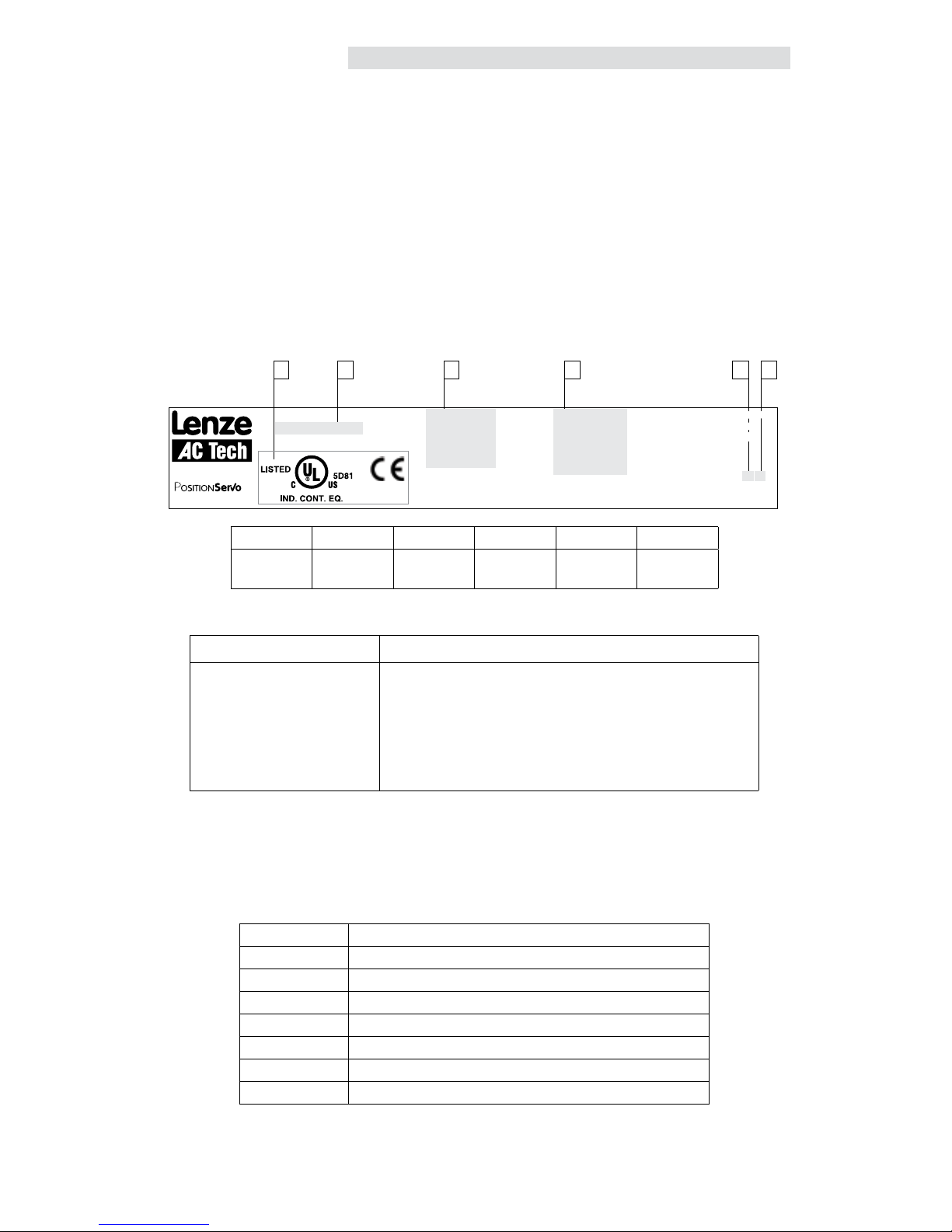
Drive Hardware Version
For hardware version 2, the drive dataplate (identification label) displays “2” in the fourth to last digit of the
drive indentification number. Refer to “E” designation in the drive identification label. Upon power-up the
drive LED display will read “9402” to indicate 940 PositionServo, hardware version 2.
If upon power-up the drive LED reads “940”, the drive has hardware version 1. Refer to User Manual
S94PM01 for hardware version 1 drives.
Drive Identification Label
C A B D E F
Type:
E94P120Y2NES
ID-No: 13014745
INPUT:
1(3)/PE
120/240 V
24.0 (13.9) A
50-60 HZ
OUTPUT:
3/PE
0 - 230 V
12.0 A
For detailed information
refer to instruction
Manual: S94H201
SN: 13014745012345678
E94P120Y2NES0XX2###
Made in USA
Model 940
13014745012345678
A B C D E F
Certifications Model
Number
Input
Ratings
Output
Ratings
Hardware
Version
Software
Version
Package Contents
Scope of Supply Important
1 Model PositionServo:
Type E94P or E94R
1 Mounting Instructions (English)
1 MotionView CD ROM including:
- configuration software
- documentation
After reception of the delivery, immediately check whether the scope
of supply matches the accompanying papers. Lenze- AC Tech does
not accept any liability for deficiencies claimed subsequently.
Claim:
- visible transport damage immediately to the forwarder
- visible deficiencies / incompleteness immediately to your Lenze
representative.
Related Documents
The documentation listed herein contains information relevant to the operation of the PositionServo and
MotionView OnBoard. To obtain the latest documentation, visit the Technical Documentation section of
http://www.lenze.com.
Table 1: Reference Documentation
Document # Description
P94MI01 PositionServo (with MVOB) Mounting Instructions
PM94H201 PositionServo (with MVOB) Programming Manual
P94MOD01 Position Servo ModBus RTU over RS485 ; Modbus TCP/IP
P94CAN01 PositionServo CANopen Communications Reference Guide
P94DVN01 PositionServo DeviceNet Communications Reference Guide
P94ETH01 PositionServo EtherNet/IP Communications Reference Guide
P94PFB01 PositionServo PROFIBUS Communications Reference Guide
Page 7
S94H201E_13426446_EN L 5
Introduction
1 Introduction
1.1 Safety Information
The safety information provided in this documentation has the layout shown herein.
Signal Word! (Characteristics the severity of the danger)
Note (describes the danger and informs on how to proceed)
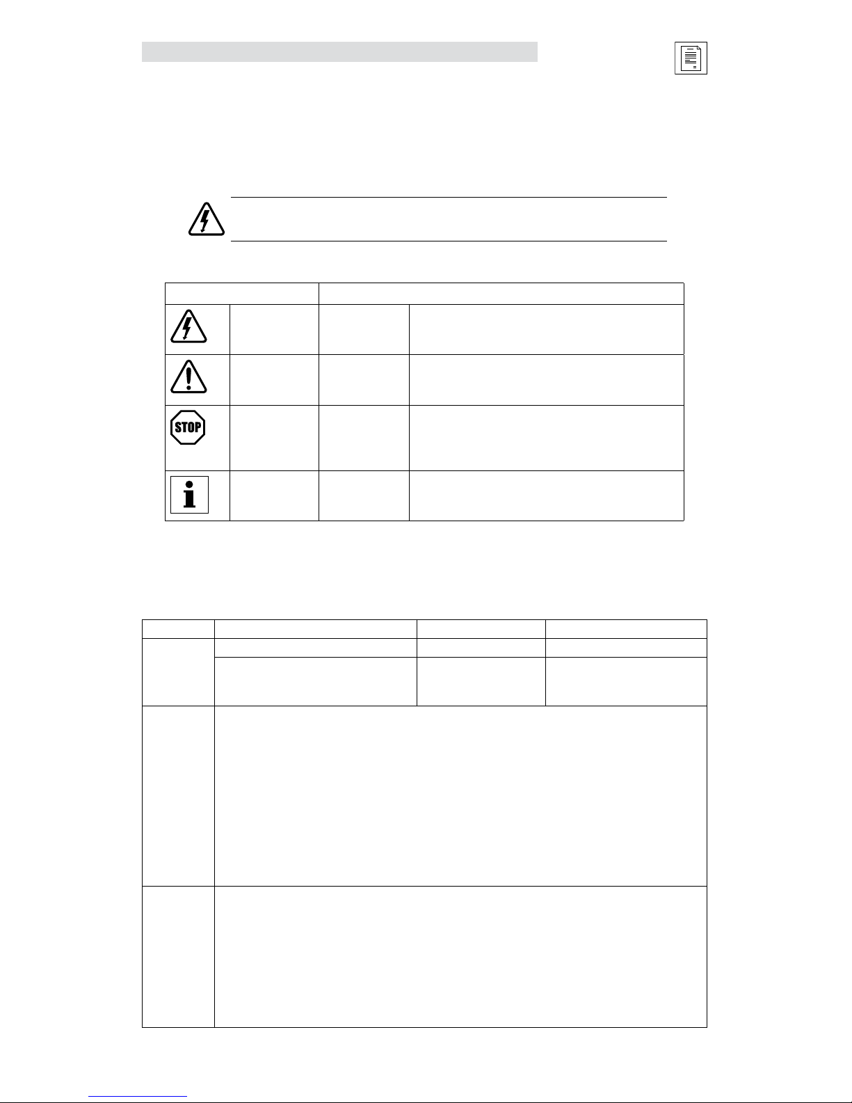
Table 2: Pictographs used in these Instructions
Icon Signal Words
Warning of
hazardous
electrical voltage
DANGER!
Warns of impending danger.
Consequences if disregarded:
Death or severe injuries.
Warning of a
general danger
WARNING!
Warns of potential, very hazardous situations.
Consequences if disregarded:
Death or severe injuries.
Warning of
damage to
equipment
STOP!
Warns of potential damage to material and
equipment.
Consequences if disregarded:
Damage to the controller/drive or its environment.
Information
NOTE
Designates a general, useful note.
If you observe it, handling the controller/drive system is
made easier.
1.2 Legal Regulations
Table 2 lists the identification, application, liability, warranty and disposal information for the PositionServo
drive.
Table 3: Legal Disclaimers
Claim Description
Identification
Nameplate CE Identification Manufacturer
Lenze controllers are unambiguously
designated by the contents of the
nameplate
In compliance with the EC
Low-Voltage Directive
Lenze AC Tech Corporation
630 Douglas Street
Uxbridge, MA 01569 USA
Application
as directed
E94P or E94R servo controller
• must only be operated under the conditions prescribed in these Instructions.
• are components for:
- Closed loop control of Velocity, Torque, or Positioning applications with AC synchronous motors.
- installation in a machine.
- assembly with other components to form a machine.
• are electric units for installation in control cabinets or similarly enclosed housing.
• comply with the requirements of the Low-Voltage Directive.
• are not machines for the purpose of the Machinery Directive.
• are not to be used as domestic appliances, but only for industrial purposes.
Application
as directed
Drive systems with E94P or E94R servo inverters
• comply with the EMC Directive if they are installed according to the guidelines of CE-typical drive
systems.
• can be used for:
- for operation on public and non-public mains
- for operation in industrial premises and residential areas.
• The user is responsible for the compliance of his application with the EC directives.
Any other use shall be deemed as inappropriate!
Note: Table 3 continued on next page.
Page 8

6 L S94H201E_13426446_EN
Introduction
Claim Description
Liability
•Theinformation,data,andnotesintheseinstructionsmetthelatestdesignandimplementationofthe
drive at the time of publication. Claims on modifications referring to controllers that have already been
supplied cannot be derived from the information, illustrations, and descriptions.
•Thespecications,processesandcircuitrydescribedintheseinstructionsareforguidanceonlyand
must be adapted to your own specific application. Lenze does not take responsibility for the suitability
of the process and circuit proposals.
•ThespecicationsintheseInstructionsdescribetheproductfeatureswithoutguaranteeingthem.
•Lenzedoesnotacceptanyliabilityfordamageandoperatinginterferencecausedby:
- Disregarding the operating instructions
- Unauthorized modifications to the controller
- Operating errors
- Improper working on and with the controller
Warranty
•Warrantyconditions:refertoLenzeACTechTermsandConditionsofSale,documentTD03.
Disposal Material Recycle Dispose
Metal • -
Plastic • -
Assembled PCB’s - •
1.3 General Drive Information
1.3.1 Mains Configuration
The PositionServo is available in four mains (input power) configurations:
1. 120/240V Single Phase (Voltage Doubler) Units
When wired for Doubler mode (L1-N), the input is for 120V nominal only and can range from 70 VAC to
132 VAC and the maximum output voltage is double the input voltage. When wired to terminals L1-L2/N,
the input can range from 80 VAC to 264 VAC and the maximum output voltage is equal to the input
voltage.
2. 120/240V Single Phase (Filtered) Units
120/240V (nominal) single phase input with integrated input mains (line) filter. Actual input voltage range:
80VAC to 264VAC. The maximum output voltage is approximately equal to the input voltage.
3. 120/240V Single or Three Phase Units
120V or 240V (nominal) single or three phase input. Actual input voltage range: 80VAC to 264VAC. The
maximum output voltage is approximately equal to the input voltage. An external input mains (line) filter is
available.
4. 400/480V Three phase Units
400/480V (nominal) three phase input. An external input mains (line) filter is available. Actual voltage
range: 320 - 528 VAC.
1.3.2 Operating Modes
The PositionServo drive can operate in one of three mode settings, torque (current), velocity, or positioning. The
drive’s command or reference signal can come from one of three sources. The first is an external reference. An
external reference can be an analog input signal, a step and direction input or an input from a master encoder.
The second reference is an internal reference. An internal reference is when the commanded reference is
derived from the drive’s user program. The third reference is when the commanded reference is given by a
host device over a communications network. This Host device can be an external motion controller, PLC, HMI
or PC. The communication network can be over, RS485 (Point-to-Point or Modbus RTU), Modbus over TCP/IP,
CANopen (DS301), EtherNet/IP, DeviceNet or PROFIBUS DP.
Page 9

S94H201E_13426446_EN L 7
Introduction
1.3.3 Feedback
Depending on the primary feedback, there are two types of drives: the Model 940 PositionServo encoderbased drive which accepts an incremental encoder with Hall channel inputs and the Model 941 PositionServo
resolver-based drive which accepts resolver inputs. The feedback signal is brought back to the P4 connector
on the drive. This connector will be a 15 pin D-sub for the encoder version and a 9 pin D-sub for the resolver
version.
1.3.4 Software
MotionView software is the setup and management tool for the PositionServo drive. All parameters can be
set and monitored via this software tool. It has a real-time oscilloscope tool for analysis and optimum tuning.
The users program, written with SimpleMotion Programming Language (SML), can be utilized to command
motion and handle the drive’s analog and digital I/O (inputs and outputs). The programming language is a
Basic-like language designed to be very intuitive and easy to implement. For programming details, refer to the
PositionServo Programming Manual. All PositionServo related manuals can be downloaded from the Technical
Documentation section on the Lenze website (http://www.lenze.com).
On each PositionServo drive, there is an Electronic Programming Module (EPM), which stores all drive setup
and tuning gain settings. This module can be removed from the drive and reinstalled into another drive, making
the field replacement of the drive extremely easy. This also makes it easy to duplicate the settings for several
drives.
The PositionServo drive supports a variety of communication protocols, including Point-to-Point (PPP), Modbus
RTU over RS485, Ethernet TCP/IP, Modbus over TCP/IP, CANopen (DS301), EtherNet/IP, DeviceNet and
PROFIBUS DP.
Page 10
8 L S94H201E_13426446_EN
Introduction
1.4 Part Number Designation
The table herein describes the part number designation for the PositionServo drive. The available filter and
communication options are detailed in separate tables.
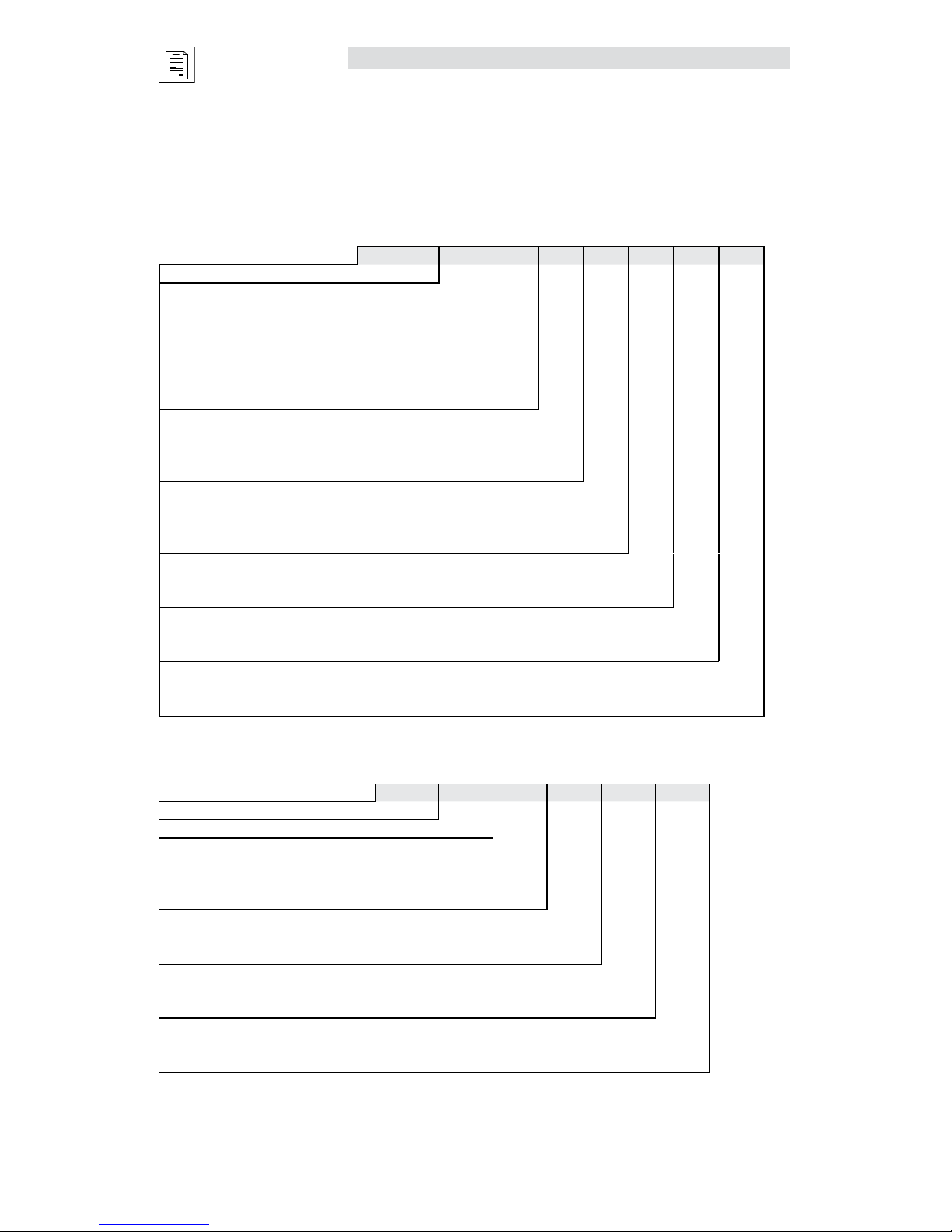
1.4.1 Drive Part Number
E94
P 020 S 1 N E M
Electrical Products in the 94x Series
P = PositionServo Model 940 with Encoder Feedback
R = PositionServo Model 941 with Resolver Feedback
Drive Rating in Amps:
020 = 2 Amps 090 = 9 Amps
040 = 4 Amps 100 = 10 Amps
060 = 6 Amps 120 = 12 Amps
080 = 8 Amps 180 = 18 Amps
Input Phase:
S = Single Phase Input only
Y = Single or Three Phase Input
T = Three Phase Input only
Input Voltage:
1 = 120 VAC Doubler (120V, 1~ in/ 240V, 3~ out)
2 = 200/240 VAC
4 = 400/480 VAC
Line Filter:
N = No Line Filter*
F = Integrated Line Filter
Secondary Feedback:
E = Incremental Encoder
R = Standard Resolver
Safety Option:
M = MotionView OnBoard, no ISO 13849-1 safety compliance
S = MotionView OnBoard, with ISO 13849-1 safety compliance
* For 3-phase EMC installation, model 940 EMC footprint/side mount filters are required.
1.4.2 Filter Part Number
E94Z
F 4 T 4
A1
Electrical Option in the 94x Series
F = EMC Filter
Filter Current Rating in Amps:
04 = 4.4 Amps 12 = 12 Amps
07 = 6.9 Amps 15 = 15 Amps
10 = 10 Amps 24 = 24 Amps
Input Phase:
S = Single Phase
T = Three Phase
Max Voltage:
2 = 240 VAC
4 = 400/480 VAC
Degree of Filtering/Variation
A1 = Industrial/1st Variation
A2 = Industrial/2nd Variation
Page 11

S94H201E_13426446_EN L 9
Introduction
1.4.3 Option Part Number
E94Z A
CAN 1
Electrical Option in the 94x Series
A = Communication or Breakout Module
Module Type:
Communication: Breakout:
CAN = CANopen COMM Module HBK = Motor Brake Terminal Module
RS4 = RS485 COMM Module TBO = Terminal Block I/O Module
DVN = DeviceNet COMM Module SCA = Panel Saver I/O Module
PFB = PROFIBUS COMM Module
Variations
1 = 1st Variation
2 = 2nd Variation
3 = 3rd Variation
Page 12

10 L S94H201E_13426446_EN
Technical Data
2 Technical Data
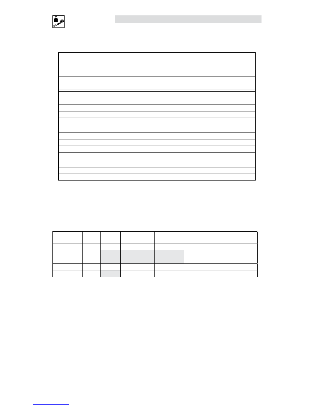
2.1 Electrical Characteristics
Single-Phase Models
Type
(1)
Mains Voltage
(2)
1~ Mains
Current
(doubler)
1~ Mains
Current
(Std.)
Rated
Output
Current
(5)
Peak
Output
Current
(6)
E94_020S1N_~
120V
(3)
or 240V
(4)
9.7 5.0 2.0 6
E94_040S1N_~ 15 8.6 4.0 12
E94_020S2F_~
120 / 240V
(4)
(80 V -0%...264 V +0%)
-- 5.0 2.0 6
E94_040S2F_~ -- 8.6 4.0 12
E94_080S2F_~ -- 15.0 8.0 24
E94_100S2F_~ -- 18.8 10.0 30
Single/Three-Phase Models
Type
(1)
Mains Voltage
(2)
1~
Mains
Current
3~
Mains
Current
Rated
Output
Current
(5)
Peak
Output
Current
(6)
E94_020Y2N_~
120 / 240V
(4)
1~ or 3~
(80 V -0%...264 V +0%)
5.0 3.0 2.0 6
E94_040Y2N_~ 8.6 5.0 4.0 12
E94_080Y2N_~ 15.0 8.7 8.0 24
E94_100Y2N_~ 18.8 10.9 10.0 30
E94_120Y2N_~ 24.0 13.9 12.0 36
E94_180T2N_~
240V 3~
(180 V -0%...264 V +0%)
-- 19.6 18.0 54
E94_020T4N_~
400 / 480V
3~
(320 V -0%...528 V +0%)
-- 2.7 2.0 6
E94_040T4N_~ -- 5.5 4.0 12
E94_060T4N_~ -- 7.9 6.0 18
E94_090T4N_~ -- 12.0 9.0 27
(1) The first “_” equals “P” for the 940 encoder based drive or “R” for the 941 resolver based drive.
The second “_” equals “E” for incremental encoder (must have E94P drive) or “R” for the standard resolver (must have E94R drive).
The last digit “~” equals “M” for MV OnBoard and no ISO 13849-1 circuit or “S” for MV OnBoard plus the ISO 13849-1 circuit.
(2)
Mains voltage for operation on 50/60 Hz AC supplies (48 Hz -0% … 62Hz +0%).
(3) Connection of 120VAC (70 V … 132 V) to input power terminals L1 and N on these models doubles the voltage on motor output
terminals U-V-W for use with 230VAC motors.
(4)
Connection of 240VAC or 120VAC to input power terminals L1 and L2 on these models delivers an equal voltage as maximum to motor
output terminals U-V-W allowing operation with either 120VAC or 230VAC motors.
(5)
Drive rated at 8kHz Carrier Frequency. Derate Continuous current by 17% at 16kHz.
(6)
Peak RMS current allowed for up to 2 seconds. Peak current rated at 8kHz. Derate by 17% at 16kHz.
(7)
Derate rated output current and peak output current by 2.5% for every ºC above 40ºC up to 55ºC maximum.
Page 13

S94H201E_13426446_EN L 11
Technical Data
Electrical Specifications applicable to all models:
Acceleration Time Range (Zero to Max Speed) 0.1 … 5x10
6
RPM/sec
Deceleration Time Range (Max Speed to Zero) 0.1 … 5x10
6
RPM/sec
Speed Regulation (typical) ± 1 RPM
Input Impedance (AIN+ to COM and AIN+ to AIN-) 47 kΩ
Power Device Carrier Frequency (sinusoidal commutation) 8, 16 kHz
Power Supply (max) +5 VDC @ 300 mA
Maximum Encoder Feedback Frequency 2.1 MHz (per channel)
Maximum Output Frequency (to motor) 400 Hz
Resolver Carrier Frequency 4.5 - 5.5kHz (5kHz nom)
Resolver Turns Ratio: Reference to SIN/COS signal 2:1
Resolver Voltage 10V peak to peak
Maximum Resolver Feedback Speed 6500 rpm
2.2 Power Ratings
Type
(1)
Output Power
at Rated Output
Current (8kHz)
(2)
Leakage Current
Power Loss at
Rated Output
Current
(8kHz)
Power Loss at
Rated Output
Current
(16 kHz)
(3)
Units kVA mA Watts Watts
E94_020S1N_~ 0.8
Typically >3.5 mA.
Consult factory for
applications requiring
<3.5 mA.
19 21
E94_040S1N_~ 1.7 29 30
E94_020S2F_~ 0.8 19 21
E94_040S2F_~ 1.7 29 30
E94_080S2F_~ 3.3 61 63
E94_100S2F_~ 4.2 80 85
E94_020Y2N_~ 0.8 19 21
E94_040Y2N_~ 1.7 29 30
E94_080Y2N_~ 3.3 61 63
E94_120Y2N_~ 5.0 114 129
E94_180T2N_~ 7.5 171 195
E94_020T4N_~ 1.7 31 41
E94_040T4N_~ 3.3 50 73
E94_060T4N_~ 5.0 93 122
E94_090T4N_~ 7.5 138 182
(1) The first “_” equals “P” for the Model 940 encoder based drive or “R” for the Model 941 resolver based drive.
The second “_” equals “E” for incremental encoder (must have E94P drive) or “R” for the standard resolver (must have E94R drive).
The last digit “~” equals “M” for MV OnBoard and no ISO 13849-1 circuit or “S” for MV OnBoard plus the ISO 13849-1 circuit.
(2) At 240 VAC line input for drives with suffixes “S1N”, “S2F”, “Y2N”. At 480 VAC line input for drives with suffixes “T4N”.
a. The output power is calculated from the formula: output kVA = [(3) x ULL x I
rated
] / 1000
b. The actual output power (kW) depends on the motor in use due to variations in motor rated voltage, rated speed and power factor, as well as actual max
operating speed and desired overload capacity.
c. Typical max continuous power (kW) for PM servo motors run 50-70% of the kVA ratings listed.
(3) At 16 kHz, de-rate continuous current by 17%
Page 14
12 L S94H201E_13426446_EN
Technical Data
2.3 Fuse Recommendations
Type
(1)
AC Line
Input Fuse
(1ø/3ø)
Miniature
Circuit Breaker
(4)
(1ø/3ø)
AC Line Input Fuse
or Breaker
(5) (6)
(N. America)
DC Bus Input
Fuse
(7)
Amp Ratings
E94_020S1N_~ M20/M10 C20/C10 20/10 10
E94_040S1N_~ M32/M20 C32/C20 30/20 20
E94_020S2F_~ M20 C20 20 15
E94_040S2F_~ M20 C20 20 20
E94_080S2F_~ M32 C32 32 40
E94_100S2F_~ M40 C40 40 45
E94_020Y2N_~ M20/M16 C20/C16 20/15 15
E94_040Y2N_~ M20/M16 C20/C16 20/15 20
E94_080Y2N_~ M32/M20 C32/C20 30/20 40
E94_120Y2N_~ M50/M32 C50/C32 50/30 55
E94_180T2N_~ M40 C40 40 80
E94_020T4N_~ M10 C10 10 10
E94_040T4N_~ M10 C10 10 20
E94_060T4N_~ M20 C20 20 30
E94_090T4N_~ M25 C25 25 40
(1) The first “_” equals “P” for the Model 940 encoder based drive or “R” for the Model 941 resolver based drive.
The second “_” equals “E” for incremental encoder (must have E94P drive) or “R” for the standard resolver (must have E94R drive).
The last digit “~” equals M” for MV OnBoard and no ISO 13849-1 circuit or “S” for MV OnBoard plus the ISO 13849-1 circuit.
(4) Installations with high fault current due to large supply mains may require a type D circuit breaker.
(5) UL Class CC or T fast-acting current-limiting type fuses, 200,000 AIC, preferred. Bussman KTK-R, JJN, JJS or equivalent.
(6) Thermal-magnetic type breakers preferred.
(7) DC-rated fuses, rated for the applied voltage. Examples Bussman KTM or JJN as appropriate.
2.4 Digital and Analog I/O Ratings
I/O Scan
Times
Linearity Temperature Drift Offset Current Input
Impedance
Voltage
Range
Units
ms % % % mA Ohm VDC
Digital Inputs
(1)
512 Depend on load 2.4 k
(2)
5-24
Digital Outputs
512 100 max N/A 30 max
Analog Inputs
512 ± 0.013 0.1% per °C rise ± 0 adjustable Depend on load 47 k ± 10
Analog Outputs
512 0.1% per °C rise ± 0 adjustable 10 max N/A ± 10
(1) Inputs do not have scan time. Their values are read directly by indexer program statement.
De-bounce time is programmable and can be set as low as 0. Propagation delay is typical 20 us
(2) Input Impedance is 1.2kΩ for drive with Hardware Revision 2A.
2.5 Environment
Vibration 2 g (10 - 2000 Hz)
Ambient Operating Temperature Range 0 to 40ºC (Derate rated output current and peak output current by 2.5% for
every ºC above 40ºC up to 55ºC)
Ambient Storage Temperature Range -10 to 70ºC
Temperature Drift 0.1% per ºC rise
Humidity 5 - 90% non-condensing
Altitude 1500m/5000ft [derate by 1% per 300m (1000 ft) above 1500m (5000 ft)]
2.6 Operating Modes
Torque
Reference ± 10 VDC 12-bit; scalable
Torque Range 100:1
Current-Loop Bandwidth Up to 1.5 kHz*
Page 15
S94H201E_13426446_EN L 13
Technical Data
Velocity
Reference ± 10 VDC or 0…10 VDC; 12-bit; scalable
Regulation ± 1 RPM
Velocity-Loop Bandwidth Up to 200 Hz*
Speed Range 5000:1 with 5000 ppr encoder
Position
Reference 0…2 MHz Step & Direction or 2 channels quadrature input; scalable
Minimum Pulse Width 500 nanoseconds
Loop Bandwidth Up to 150 Hz*
Accuracy ±1 encoder count for encoder feedabck
±1.32 arc-minutes for resolver feedback (14-bit resolution)
* = motor and application dependent
2.7 Connections and I/O
Mains Power 3-pin or 4-pin removable terminal block (P1)
Ethernet Port Standard RJ45 Connector (P2)
I/O Connector Standard 50-pin SCSI (P3)
- Buffered Encoder Output A, B, & Z channels with compliments (5V @ 20mA) (P3)
- Digital Inputs 11 programmable plus 1 dedicated (5-24V) (P3)
- Digital Outputs 4 programmable plus 1 dedicated (5-24V @ 100mA) (P3)
- Analog Input 2 differential; ±10 VDC (12-bits each) (P3)
- Analog Output 1 single ended; ±10 VDC (10-bit) (P3)
- Position Reference Input Step & Direction or Master Encoder (TTL) (P3)
Encoder Feedback (E94P drive) Feedback connector, 15-pin D-shell (P4)
Resolver Feedback (E94R drive) Feedback connector, 9-pin D-shell (P4)
24VDC Power “Keep Alive” 2-pin removable terminal block (P5)
Regen and Bus Power 5-pin removable terminal block (P6)
Motor Power 6-pin pin removable terminal block (P7)
ISO 13849-1 Safety Circuit (option) 6-pin quick connect terminal block (P8)
RS485 Option Module 3-pin terminal block (installed in Option Bay 1) (P21)
CAN Option Module 3-pin terminal block (installed in Option Bay 1) (P21)
DeviceNet Option Module 5-pin terminal block (installed in Option Bay 1) (P23)
PROFIBUS Option Module 9-pin D-shell connector (installed in Option Bay 1) (P24)
MotionView OnBoard Embedded Software (Java-based)
Maximum Servo Cable Length 20 meters (10m if EN55011 compliance required, see 3.2.1)
P2
P3
P1
P4
P5
P6
P7
EPM
W
V
U
T2
T1
9
4
0
2
8
d
i
S
P8
Ground Lug
Ground Lug
L3
L2
L1
1
2
3
4
5
6
Page 16
14 L S94H201E_13426446_EN
Technical Data
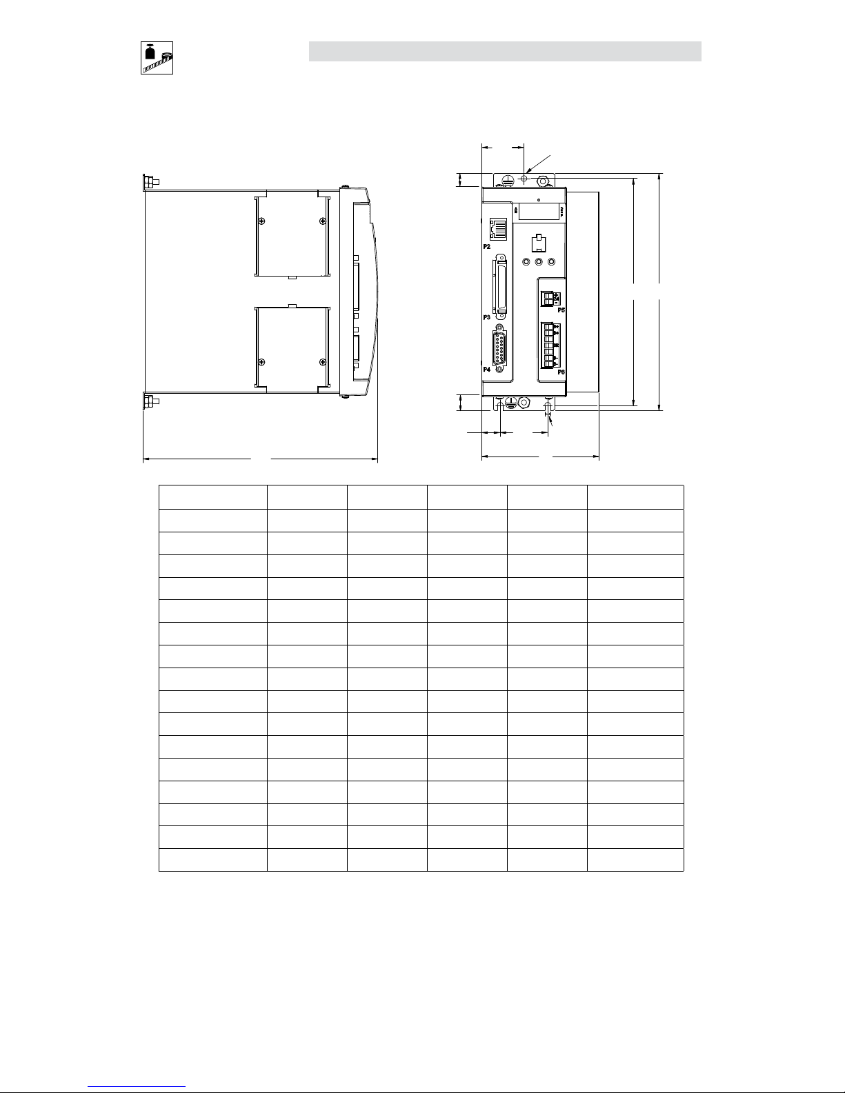
2.8 PositionServo Dimensions
C
15
12
12
A
38
D B
34
dia = 4.57
4.57
Dimensions in mm
S923
Type
(1)
A (mm) B (mm) C (mm) D (mm) Weight (kg)
E94_020S1N_~ 68 190 190 182 1.1
E94_040S1N_~ 69 190 190 182 1.2
E94_020S2F_~ 68 190 235 182 1.3
E94_040S2F_~ 69 190 235 182 1.5
E94_080S2F_~ 87 190 235 182 1.9
E94_100S2F_~ 102 190 235 182 2.2
E94_020Y2N_~ 68 190 190 182 1.3
E94_040Y2N_~ 69 190 190 182 1.5
E94_080Y2N_~ 95 190 190 182 1.9
E94_100Y2N_~ 114 190 190 182 2.2
E94_120Y2N_~ 68 190 235 182 1.5
E94_180T2N_~ 68 242 235 233 2.0
E94_020T4N_~ 68 190 190 182 1.5
E94_040T4N_~ 95 190 190 182 1.9
E94_060T4N_~ 68 190 235 182 1.4
E94_090T4N_~ 68 242 235 233 2.0
(1) The first “_” equals “P” for the Model 940 encoder based drive or “R” for the Model 941 resolver based drive.
The second “_” equals “E” for incremental encoder (must have E94P drive) or “R” for the standard resolver (must have E94R drive).
The last digit “~” equals M” for MV OnBoard and no ISO 13849-1 circuit or “S” for MV OnBoard plus the ISO 13849-1 circuit.
Page 17
S94H201E_13426446_EN L 15
Technical Data
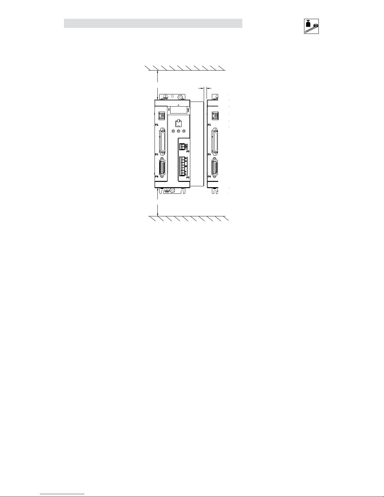
2.9 Clearance for Cooling Air Circulation
>25mm
>3mm
>25mm
S924
Page 18
16 L S94H201E_13426446_EN
Installation
3 Installation
Perform the minimum system connection. Refer to section 6.1 for minimum connection requirements.
Observe the rules and warnings below carefully:
DANGER!
Hazard of electrical shock! Circuit potentials are up to 480 VAC above earth ground. Avoid
direct contact with the printed circuit board or with circuit elements to prevent the risk of
serious injury or fatality. Disconnect incoming power and wait 60 seconds before servicing
drive. Capacitors retain charge after power is removed.
STOP!
• The PositionServo must be mounted vertically for safe operation and to ensure
enough cooling air circulation.
• Printed circuit board components are sensitive to electrostatic fields. Avoid contact
with the printed circuit board directly. Hold the PositionServo by its case only.
• Protect the drive from dirt, filings, airborne particles, moisture, and accidental
contact. Provide sufficient room for access to the terminal block.
• Mount the drive away from any and all heat sources. Operate within the specified
ambient operating temperature range. Additional cooling with an external fan may
be required in certain applications.
• Avoid excessive vibration to prevent intermittent connections
• DO NOT connect incoming (mains) power to the output motor terminals (U, V, W)!
Severe damage to the drive will result.
• Do not disconnect any of the motor leads from the PositionServo drive unless
(mains) power is removed. Opening any one motor lead may cause failure.
• Control Terminals provide basic isolation (insulation per EN 61800-5-1). Protection
against contact can only be ensured by additional measures, e.g., supplemental
insulation.
• Do not cycle mains power more than once every 2 minutes. Otherwise damage to
the drive may result.
WARNING!
For compliance with EN 61800-5-1, the following warning applies.
This product can cause a d.c. current in the protective earthing conductor. Where
a residual current-operated protective (RCD) or monitoring (RCM) device is used for
protection in case of direct or indirect contact, only an RCD or RCM of Type B is
allowed on the supply side of this product.
UL INSTALLATION INFORMATION
• Suitable for use on a circuit capable of delivering not more than 200,000
rms symmetrical amperes, at the maximum voltage rating marked on the
drive.
• Use Class 1 wiring with minimum of 75ºC copper wire only.
• Shall be installed in a pollution degree 2 macro-environment.
• The PositionServo does not provide motor over-temperature protection. The
user may connect a KTY motor thermal sensor to the drive as detailed in
section 4.1.1 and 4.5.2 if necessary to satisfy NEC requirements.
Page 19
S94H201E_13426446_EN L 17
Installation
3.1 Wiring
DANGER!
Hazard of electrical shock! Circuit potentials are up to 480 VAC above earth ground. Avoid
direct contact with the printed circuit board or with circuit elements to prevent the risk of
serious injury or fatality. Disconnect incoming power and wait 60 seconds before servicing
the drive. Capacitors retain charge after power is removed.
WARNING!
Leakage current may exceed 3.5mA AC. Minimum size of the protective earth conductor
shall comply with local safety regulations for high leakage current equipment.
STOP!
Under no circumstances should power and control wiring be bundled together. Induced
voltage can cause unpredictable behavior in any electronic device, including motor controls.
WARNING!
The PositionServo drive runs on phase-to-phase voltage. For the standard drive, either a
delta or wye transformer may be used for 3-phase input. However, for reinforced insulation
of user accessible I/O circuits, each phase voltage to ground must be less than or equal to
300VAC rms. This means that the power system must use center grounded wye secondary
configuration for 400/480VAC mains.
Refer to section 4.1.1 for Power wiring specifications.
3.2 Shielding and Grounding
3.2.1 General Guidelines
Lenze recommends the use of single-point grounding (SPG) for panel-mounted controls. Serial grounding
(a “daisy chain”) is not recommended. The SPG for all enclosures must be tied to earth ground at the same
point. The system ground and equipment grounds for all panel-mounted enclosures must be individually
connected to the SPG for that panel using 14 AWG (2.5 mm2) or larger wire.
In order to minimize EMI, the chassis must be grounded to the mounting. Use 14 AWG (2.5 mm
2
) or larger
wire to join the enclosure to earth ground. A lock washer must be installed between the enclosure and
ground terminal. To ensure maximum contact between the terminal and enclosure, remove paint in a
minimum radius of 0.25 in (6 mm) around the screw hole of the enclosure.
Lenze recommends the use of the special PositionServo drive cables provided by Lenze. If you specify cables
other than those provided by Lenze, please make certain all cables are shielded and properly grounded.
It may be necessary to earth ground the shielded cable. Ground the shield at both the drive end and at the
motor end.
If the PositionServo drive continues to pick up noise after grounding the shield, it may be necessary to add
an AC line filtering device and/or an output filter (between the drive and servo motor).
Page 20
18 L S94H201E_13426446_EN
Installation
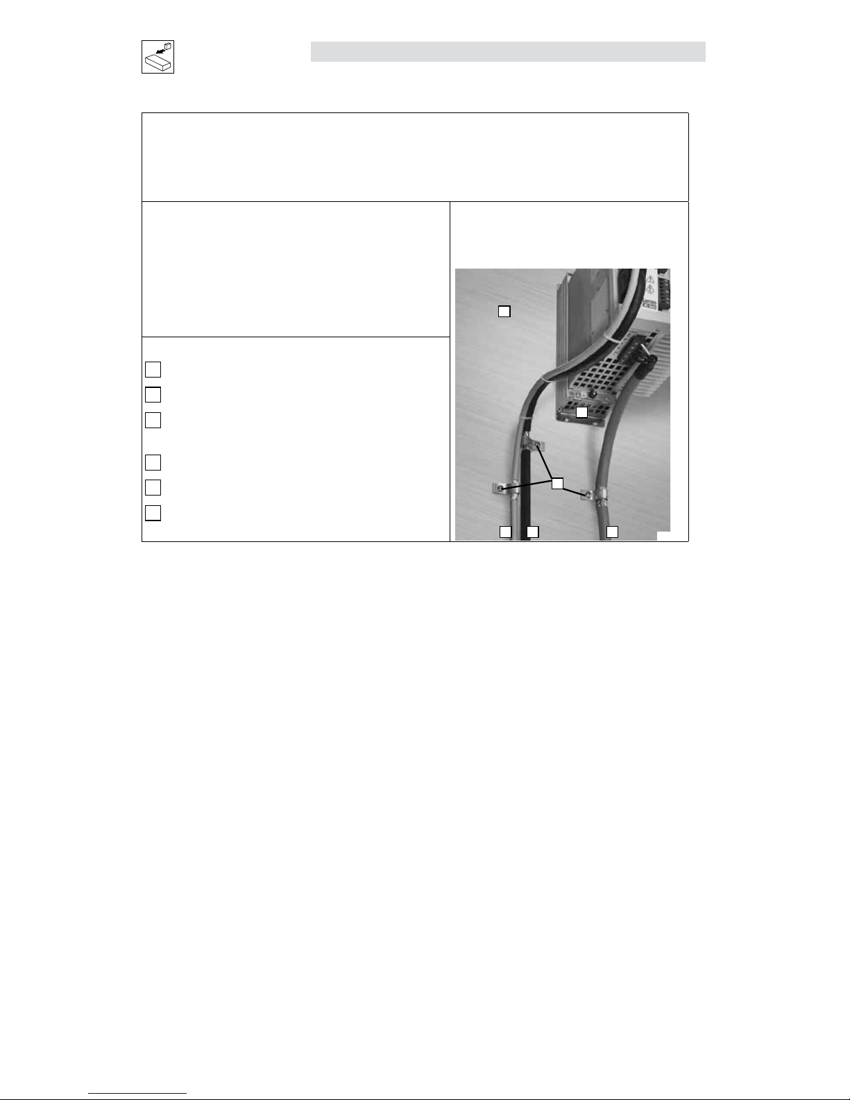
EMC
Compliance with EN 61800-3:2004
In a domestic environment this product may cause radio interference. The user may be required to
take adequate measures
Noise emission
Drive Models ending in the suffix “2F” are in compliance
with class A limits according to EN 55011 if installed
in a control cabinet and the motor cable length does
not exceed 10m. Models ending in “N” will require an
appropriate line filter.
Installation according to EMC
Requirements
E
D
B C
A
F
S930
A
Screen clamps
B
Control cable
C
Low-capacitance motor cable
(core/core < 75 pF/m, core/screen < 150 pF/m)
D
Earth grounded conductive mounting plate
E
Encoder/Resolver Feedback Cable
F
Footprint or Sidemount Filter (optional)
3.2.2 EMI Protection
Electromagnetic interference (EMI) is an important concern for users of digital servo control systems. EMI
will cause control systems to behave in unexpected and sometimes dangerous ways. Therefore, reducing
EMI is of primary concern not only for servo control manufacturers such as Lenze, but the user as well.
Proper shielding, grounding and installation practices are critical to EMI reduction.
3.2.3 Enclosure
The panel in which the PositionServo is mounted must be made of metal, and must be grounded using the
SPG method outlined in section 3.2.1.
Proper wire routing inside the panel is critical; power and logic leads must be routed in different avenues
inside the panel.
You must ensure that the panel contains sufficient clearance around the drive. Refer to section 2.9
suggested cooling air clearance.
3.3 Line Filtering
In addition to EMI/RFI safeguards inherent in the PositionServo design, external filtering may be required. High
frequency energy can be coupled between the circuits via radiation or conduction. The AC power wiring is
one of the most important paths for both types of coupling mechanisms. In order to comply with IEC 618003:2004, an appropriate filter must be installed within 20cm of the drive power inputs.
Line filters should be placed inside the shielded panel. Connect the filter to the incoming power lines
immediately after the safety mains and before any critical control components. Wire the AC line filter as
close as possible to the PositionServo drive.
Page 21

S94H201E_13426446_EN L 19
Installation
NOTE
The ground connection from the filter must be wired to solid earth ground, not machine
ground.
If the end-user is using a CE-approved motor, the AC filter combined with the recommended motor and
encoder feedback cables (maximum cable length of 10m), is all that is necessary to meet the EMC directives
listed herein. The end user must use the compatible filter to comply with CE specifications. The OEM may
choose to provide alternative filtering that encompasses the PositionServo drive and other electronics within
the same panel. The OEM has this liberty because CE requirements are for the total system.
3.4 Heat Sinking
The PositionServo drive contains sufficient heat sinking within the specified ambient operating temperature
in its basic configuration. There is no need for additional heat sinking. However, the user must ensure that
there is sufficient clearance for proper air circulation. As a minimum, an air gap of 25 mm above and below
the drive is necessary.
3.5 Line (Mains) Fusing
External line fuses must be installed on all PositionServo drives. Connect the external line fuse in series with
the AC line voltage input. Use fast-acting fuses rated for 250 VAC or 600 VAC (depending on model), and
approximately 200% of the maximum RMS phase current. Refer to section 2.3 for fuse recommendations.
Page 22
20 L S94H201E_13426446_EN
Interface
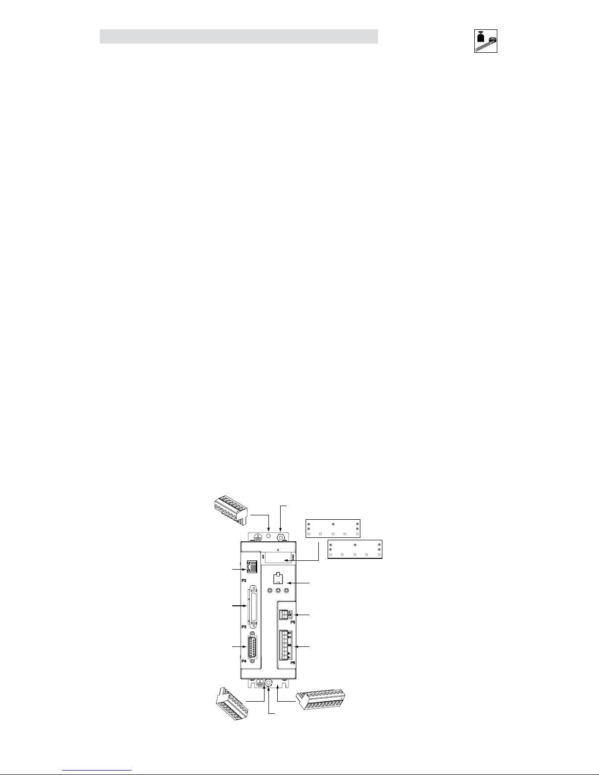
4 Interface
The standard PositionServo drive is equipped with seven connectors including: four quick-connect terminal
blocks, one SCSI connector, one subminiature type “D” connector and one ethernet RJ45 connector. These
connectors provide communications from a PLC or host controller, power to the drive, and feedback from
the motor. Prefabricated cable assemblies may be purchased from Lenze to facilitate wiring the drive, motor
and host computer. Contact your Lenze Sales Representative for assistance.
As this manual makes reference to specific pins on specific connectors, the convention PX.Y is used, where
X is the connector number and Y is the pin number.
4.1 External Connectors
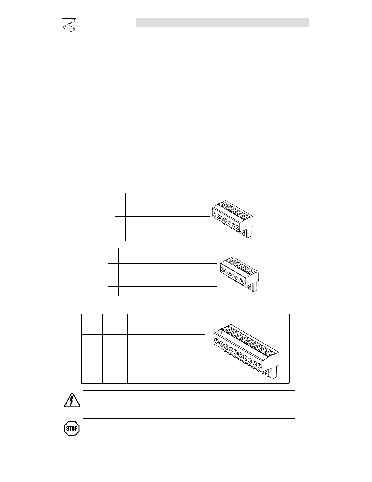
4.1.1 P1 & P7 - Input Power and Output Power Connections
Located on the top of the drive, P1 is a 3 or 4-pin quick-connect terminal block used for input (mains) power.
Located on the bottom of the drive, P7 is a 6-pin quick-connect terminal block used for output power to the
motor. P7 also has a thermistor (PTC) input for motor over-temperature protection (refer to paragraph 4.5.2).
The P1 and P7 connector pin assignments are listed in the tables herein.
P1 Pin Assignments (Input Power)
Standard Models
1
2
3
4
L3
L2
L1
PE
Pin Name Function
1 PE Protective Earth (Ground)
2 L1 AC Power in
3 L2 AC Power in
4 L3 AC Power in (3~ models only)
Doubler Models
1
2
3
4
L2/N
L1
N
PE
Pin Name Function
1 PE Protective Earth (Ground)
2 N AC Power Neutral (120V Doubler only)
3 L1 AC Power in
4 L2/N AC Power in (non-doubler operation)
P7 Pin Assignments (Output Power)
Pin Terminal Function
1
2
3
4
5
W
V
U
6
T2
T1
1 T1 Thermistor (PTC) Input
2 T2 Thermistor (PTC) Input
3 U Motor Power Out
4 V Motor Power Out
5 W Motor Power Out
6 PE Protective Earth (Chassis Ground)
DANGER!
Hazard of electrical shock! Circuit potentials are up to 480 VAC above earth ground. Avoid direct contact with
the printed circuit board or with circuit elements to prevent the risk of serious injury or fatality. Disconnect
incoming power and wait 60 seconds before servicing drive. Capacitors retain charge after power is removed.
STOP!
DO NOT connect incoming power to the output motor terminals (U, V, W)! Severe damage to the PositionServo
will result.
Check phase wiring (U, V, W) and thermal input (T1, T2) before powering up drive. If miswired, severe damage
to the PositionServo will result.
Page 23
S94H201E_13426446_EN L 21
Interface
All conductors must be enclosed in one shield with a jacket around them. The shield on the drive end of the
motor power cable should be terminated to the conductive machine panel using screen clamps as shown in
section 3.2. The other end should be properly terminated at the motor shield. Feedback cable shields should
be terminated in a like manner. Lenze recommends Lenze cables for both the motor power and feedback.
These are available with appropriate connectors and in various lengths. Contact your Lenze representative
for assistance.
Wire Size
Current
A (rms)
Terminal
Torque (lb-in)
Wire Size
I<8 4.5 16 AWG (1.5mm2) or 14 AWG (2.5mm2)
8<I<12 4.5 14 AWG (2.5mm2) or 12 AWG (4.0mm2)
12<I<15 4.5 12 AWG (4.0mm2)
15<I<20 5.0 - 7.0 10 AWG (6.0mm2)
20<I<24 11.0 - 15.0 10 AWG (6.0mm2)
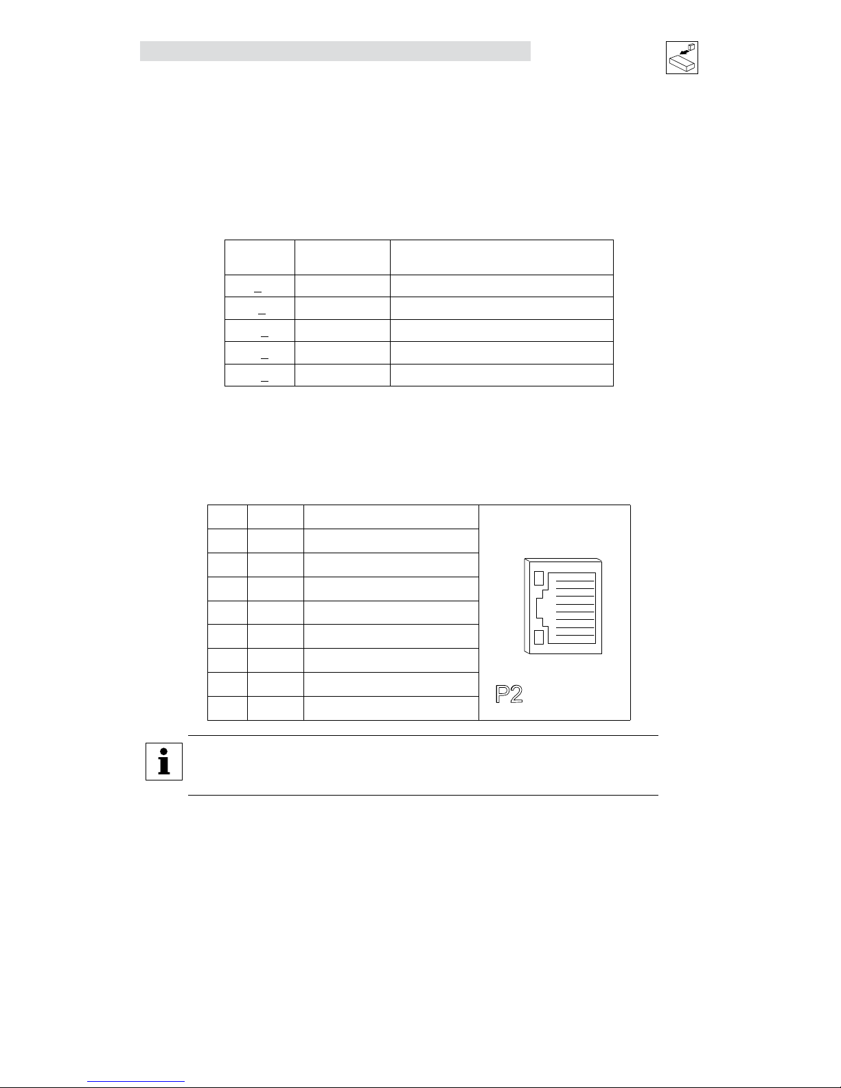
4.1.2 P2 - Ethernet Communications Port
P2 is a RJ45 Standard Ethernet connector that is used to communicate with a host computer via Ethernet
TCP/IP.
P2 Pin Assignments (Communications)
Pin Name Function
ETHERNET
1
8
P2
1 + TX Transmit Port (+) Data Terminal
2 - TX Transmit Port (-) Data Terminal
3 + RX Receive Port (+) Data Terminal
4 N.C.
5 N.C.
6 - RX Receive Port (-) Data Terminal
7 N.C.
8 N.C.
NOTE
To communicate from the PC directly to the drive a crossover cable is recommended. If
using a hub or switch, use a regular patch cable.
Page 24
22 L S94H201E_13426446_EN
Interface
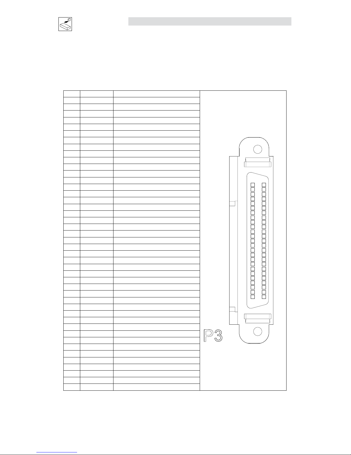
4.1.3 P3 - Controller I/O
P3 is a 50-pin SCSI connector to interface with the front-end of the controller. It is strongly recommended
that OEM cables be used to aid in satisfying CE requirements. Contact your Lenze representative for
assistance.
P3 Pin Assignments (Controller Interface)
Pin Name Function
CONTROLLER I/O
1
25
P3
50
26
1 MA+ Master Encoder A+ / Step+ input
(2)
2 MA- Master Encoder A- / Step- input
(2)
3 MB+ Master Encoder B+ / Direction+ input
(2)
4 MB- Master Encoder B- / Direction- input
(2)
5 GND Drive Logic Common
6 5+ +5V output (max 100mA)
7 BA+ Buffered Encoder Output: Channel A+
(1)
8 BA- Buffered Encoder Output: Channel A-
(1)
9 BB+ Buffered Encoder Output: Channel B+
(1)
10 BB- Buffered Encoder Output: Channel B-
(1)
11 BZ+ Buffered Encoder Output: Channel Z+
(1)
12 BZ- Buffered Encoder Output: Channel Z-
(1)
13-19 Empty
20 AIN2+ Positive (+) of Analog signal input
21 AIN2- Negative (-) of Analog signal input
22 ACOM Analog common
23 AO Analog output (max 10 mA)
24 AIN1+ Positive (+) of Analog signal input
25 AIN1 - Negative (-) of Analog signal input
26 IN_A_COM Digital input group ACOM terminal
(3)
27 IN_A1 Digital input A1
28 IN_A2 Digital input A2
29 IN_A3 Digital input A3
(3)
30 IN_A4 Digital input A4
31 IN_B_COM Digital input group BCOM terminal
32 IN_B1 Digital input B1
33 IN_B2 Digital input B2
34 IN_B3 Digital input B3
35 IN_B4 Digital input B4
36 IN_C_COM Digital input group CCOM terminal
37 IN_C1 Digital input C1
38 IN_C2 Digital input C2
39 IN_C3 Digital input C3
40 IN_C4 Digital input C4
41 RDY+ Ready output Collector
42 RDY- Ready output Emitter
43 OUT1-C Programmable output #1 Collector
44 OUT1-E Programmable output #1 Emitter
45 OUT2-C Programmable output #2 Collector
46 OUT2-E Programmable output #2 Emitter
47 OUT3-C Programmable output #3 Collector
48 OUT3-E Programmable output #3 Emitter
49 OUT4-C Programmable output #4 Collector
50 OUT4-E Programmable output #4 Emitter
(1) Refer to Note 1, Section 4.1.7 - Connector and Wiring Notes
(2) Refer to Note 2, Section 4.1.7 - Connector and Wiring Notes
(3) Refer to Note 3, Section 4.1.7 - Connector and Wiring Notes
Page 25
S94H201E_13426446_EN L 23
Interface
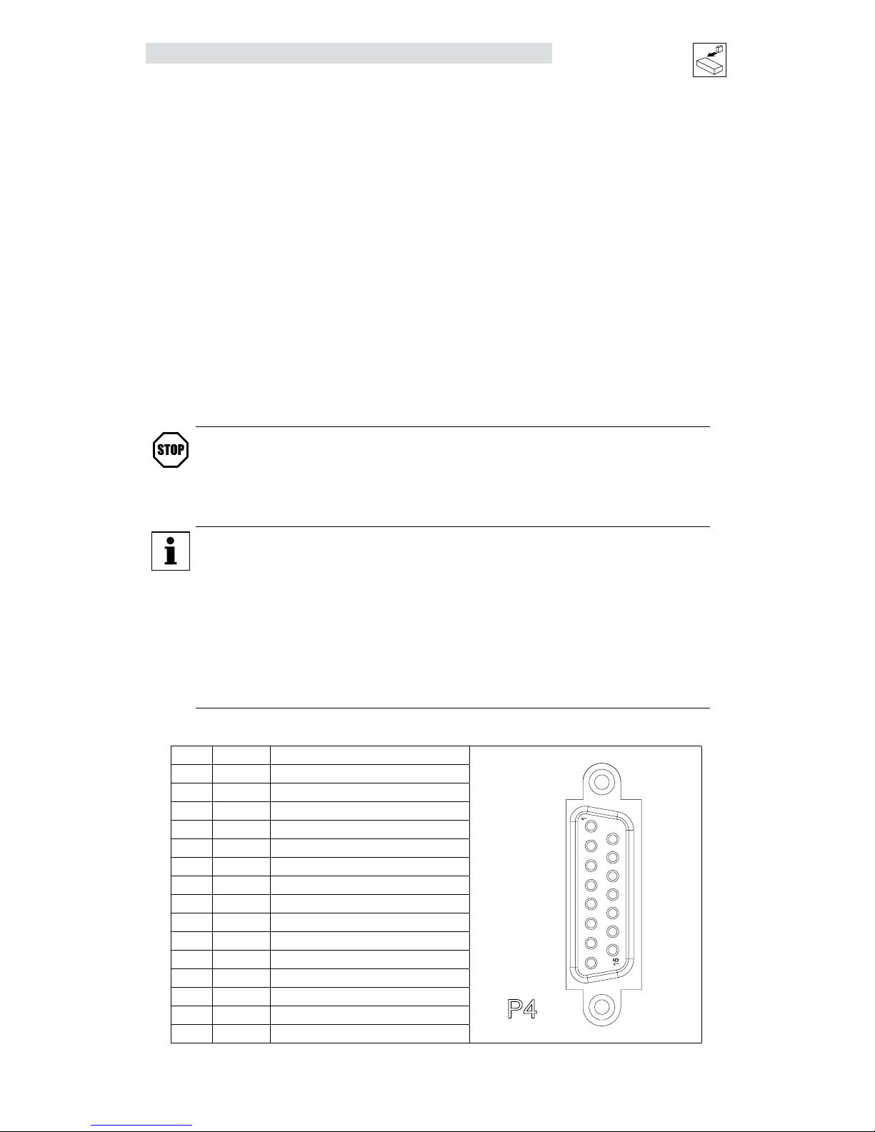
4.1.4 P4 - Motor Feedback
For encoder-based 940 drives, P4 is a 15-pin DB connector that contains connections for an incremental
encoder with Hall emulation tracks or Hall sensors. For synchronous servo motors, Hall sensors or Hall
emulation tracks are necessary for commutation. For pin assignments, refer to the Table P4A. Encoder
inputs on P4 have 26LS32 or compatible differential receivers for increased noise immunity. Inputs have all
necessary filtering and line balancing components so no external noise suppression networks are needed.
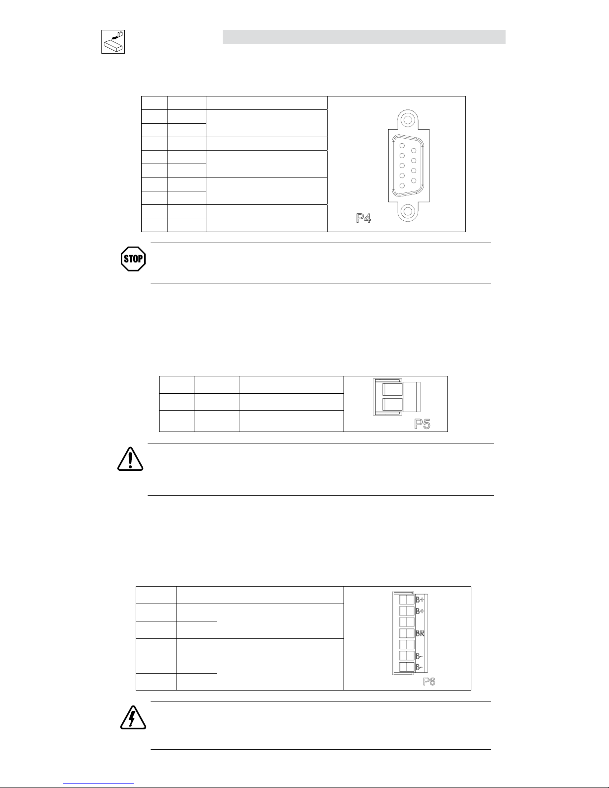
For resolver-based 941 drives, P4 is a 9-pin DB connector for connecting resolver feedback and thermal
sensor. For pin assignments, refer to the Table P4B. The resolver feedback is translated to 65,536 counts
per revolution.
All conductors must be enclosed in one shield with a jacket around them. Lenze recommends that each and
every pair (for example, EA+ and EA-) be twisted. In order to satisfy CE requirements, use of an OEM cable
is recommended. Contact your Lenze representative for assistance.
The PositionServo buffers encoder/resolver feedback from P4 to P3. For example, when encoder feedback
is used, channel A on P4, is Buffered Encoder Output channel A on P3. For more information on this refer to
section 4.2.2 “Buffered Encoder Outputs”.
STOP!
Use only +5 VDC encoders. Do not connect any other type of encoder to the PositionServo
reference voltage terminals. When using a front-end controller, it is critical that the +5 VDC
supply on the front-end controller NOT be connected to the PositionServo’s +5 VDC supply,
as this will result in damage to the PositionServo.
NOTE
• The PositionServo encoder inputs are designed to accept differentially driven hall signals.
Single-ended or open-collector type hall signals are also acceptable by connecting
“HA+”, “HB+”, “HC+” and leaving “HA-,HB-,HC-” inputs unconnected. The user does
not need to supply pull-up resistors for open-collector hall sensors. The necessary pullup circuits are already provided.
• Encoder connections (A, B and Z) must be full differential. The PositionServo does not
support single-ended or open-collector type outputs from the encoder.
• An encoder resolution of 2000 PPR (pre-quadrature) or higher is recommended.
P4A Pin Assignments (Encoder Feedback - E94P Drives)
Pin Name Function
ENCODER
1
8
P4
15
9
1 EA+ Encoder Channel A+ Input
(1)
2 EA- Encoder Channel A- Input
(1)
3 EB+ Encoder Channel B+ Input
(1)
4 EB- Encoder Channel B- Input
(1)
5 EZ+ Encoder Channel Z+ Input
(1)
6 EZ- Encoder Channel Z- Input
(1)
7 GND Drive Logic Common/Encoder Ground
8 SHLD Shield
9 PWR Encoder supply (+5VDC)
10 HA- Hall Sensor A- Input
(2)
11 HA+ Hall Sensor A+ Input
(2)
12 HB+ Hall Sensor B+ Input
(2)
13 HC+ Hall Sensor C+ Input
(2)
14 HB- Hall Sensor B- Input
(2)
15 HC- Hall Sensor C- Input
(2)
(1) Refer to Note 1, Section 4.1.7 - Connector and Wiring Notes
(2) For asynchronous servo motor, an incremental encoder without Hall effect sensors (commutation tracks) can be used.
Page 26
24 L S94H201E_13426446_EN
Interface
P4B Pin Assignments (Resolver Feedback - E94R Drives)
Pin Name Function
RESOLVER
1
5
P4
9
6
1 Ref +
Resolver reference connection
2 Ref -
3 N/C No Connection
4 Cos+
Resolver Cosine connections
5 Cos-
6 Sin+
Resolver Sine connections
7 Sin-
8 PTC+
Motor PTC Temperature Sensor
9 PTC-
STOP!
Use only 10 V (peak to peak) or less resolvers. Use of higher voltage resolvers may result
in feedback failure and damage to the drive.
4.1.5 P5 - 24 VDC Back-up Power Input
P5 is a 2-pin quick-connect terminal block that can be used with an external 24 VDC (500mA) power supply
to provide “Keep Alive” capability: during a power loss, the logic and communications will remain active.
Applied voltage must be greater than 20VDC.
P5 Pin Assignments (Back-up Power)
Pin Name Function
+
-
+
-
24
1 +24 VDC Positive 24 VDC Input
2 Return 24V power supply return
WARNING!
Hazard of unintended operation! When the enable input remains asserted, the “Keep Alive”
circuit will restart the motor upon restoration of mains power. If this action is not desired,
then remove the enable input prior to re-application of input power.
4.1.6 P6 - Braking Resistor and DC Bus
P6 is a 5-pin quick-connect terminal block that can be used with an external braking resistor (the
PositionServo has the regen circuitry built-in). The Brake Resistor connects between the Positive DC Bus
(either P6.1 or 2) and P6.3.
P6 Terminal Assignments (Brake Resistor and DC Bus)
Pin Terminal Function
B+
B-
BR
B-
B+
1 B+
Positive DC Bus / Brake Resistor
2 B+
3 BR Brake Resistor
4 B-
Negative DC Bus
5 B-
DANGER!
Hazard of electrical shock! Voltage up to 480 VAC above earth ground is possible. Avoid direct contact
with live terminals and circuit elements. Disconnect incoming power and wait 60 seconds before
opening or servicing the drive. Capacitors retain charge after power is removed.
Page 27
S94H201E_13426446_EN L 25
Interface
4.1.7 Connector and Wiring Notes
Note 1 - Buffered Encoder Outputs
Each of the encoder output pins on P3 is a buffered pass-through of the corresponding input signal on P4,
Refer to section 4.2.2 “Buffered Encoder Outputs”. This can be either from a motor mounted encoder or
an encoder emulation of the resolver. The parameter “Resolver Tracks” configures the resolution of the
encoder emulation (refer to 5.3.17).
Note 2 - Master Encoder Inputs or Step/Direction Inputs
An external pulse train signal (“step”) supplied by an external device, such as a PLC or stepper indexer, can
control the speed and position of the servomotor. The speed of the motor is controlled by the frequency of
the “step” signal, while the number of pulses that are supplied to the PositionServo determines the position
of the servomotor. Direction input controls direction of the motion.
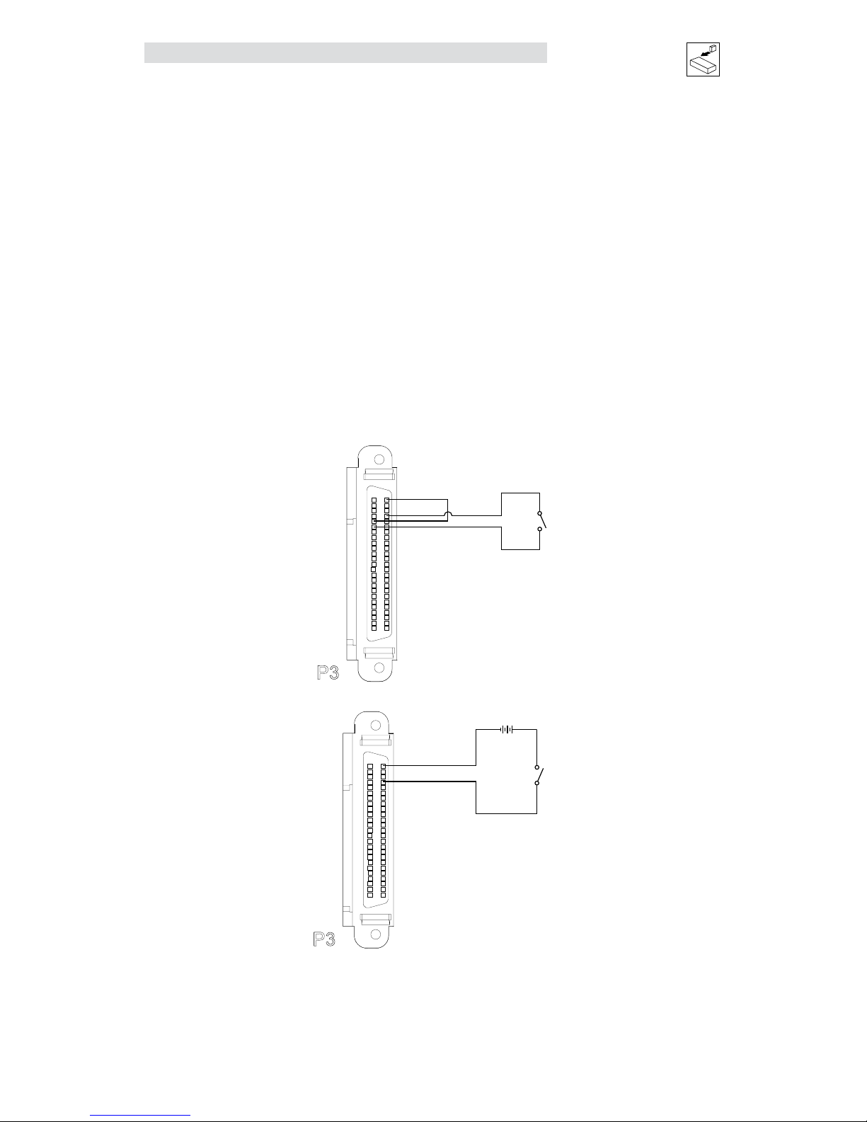
Note 3 - Digital Input A3
For the drive to function, an ENABLE input must be wired to the drive, and should be connected to IN_A3,
(P3.29), which is, by the default the ENABLE input on the drive. This triggering mechanism can either be
a switch or an input from an external PLC or motion controller. The input can be wired either sinking or
sourcing (section 4.2.3). The Enable circuit will accept 5-24V control voltage.
Wiring the ENABLE Switch:
Pin 6 +5V
Pin 5 GND
Pin 26 IN_A_COM
Pin 29 IN-A3
CONTROLLER I/O
1
25
P3
50
26
Power Supply
Pin 26 IN_A_COM
Pin 29 IN-A3
-
+
CONTROLLER I/O
1
25
P3
50
26
Page 28
26 L S94H201E_13426446_EN
Interface
4.1.8 P8 - ISO 13849-1 Safety Circuit (option)
If installed, the ISO 13849-1 Safety Circuit connector, P8, is located on the bottom of the PositionServo. P8,
a 6-pin quick-connect terminal block.
P8 Pin Assignments (ISO 13849-1 Safety Function)
Pin Name Function
1
4
3
1
5
2
2
3
4
5
6
6
1 Bypass Voltage ISO 13849-1Bypass Voltage (+24VDC)
2 Bypass COM ISO 13849-1 Bypass Common
3 Safety Status ISO 13849-1 Safety Status
4 Safety Input1 ISO 13849-1 Safety Input 1 (+24VDC to Enable)
5 Safety COM ISO 13849-1 Safety Common
6 Safety Input2 ISO 13849-1 Safety Input 2 (+24VDC to Enable)
WARNING!
The drive is supplied from the factory with the ISO 13849-1 safety circuit enabled. The drive is not operational until +24V
is present at terminals 4 and 6. For the proper safety connections, refer to the “Connection of Two Safety Circuits with
External +24V Supply” diagram. Under certain applications when safety connections are not required the drive may be
operated with the safety circuit disabled. The diagram below illustrates how to bypass the safety circuit.
Wiring Diagram to Bypass ISO 13849-1 Safety Circuit
Pin Name Function
P1
P2
P3
P4
P5
P6
1 Bypass Voltage ISO 13849-1 Bypass Voltage (+24VDC)
*1
2 Bypass COM ISO 13849-1 Bypass Common
*1
3 Safety Status ISO 13849-1 Safety Status
4 Safety Input1 ISO 13849-1 Safety Input 1 (+24VDC to Enable)
*2, *3
5 Safety COM ISO 13849-1 Safety Common
*2, *3
6 Safety Input2 ISO 13849-1 Safety Input 2 (+24VDC to Enable)
*2, *3
*1 – This voltage must under no circumstances be used to supply the ISO 13849-1 Safety circuits (terminals 3 to 6). This voltage is intended only for use
in bypassing (disabling) the ISO 13849-1 circuits should they not be required.
*2 – A Separate +24VDC supply providing reinforced isolation (SELV or PELV), must be supplied to operate these inputs. This supply should not be floating
but should be referenced within 20V peak of PE at the drive.
*3 – Unsnubbed inductive loads must NOT be used on the 24VDC safety circuit wiring.
PositionServo drives with the following “S” designation in the model number have been fitted with the
optional ISO 13849-1 Safe Torque Off function.
Drive Model Number: E94 P 020 S 1 N E
S
The last “S” denotes ISO 13849-1
option fitted to drive at manufacturer.
This option can only be fitted at the factory at the time of unit manufacturer.
This option provides additional methods (Inputs) to disable the drive output so that the drive cannot cause
torque to be generated in the motor. This safety function is often referred to as the “Safe Torque Off”
function and meets the requirements of the following standard: ISO 13849-1 Safety of Machinery, Safetyrelated Parts of Control Systems, Category (Cat.) 3, Performance Level (PL) d and Safety Integrity Level (SIL)
2, per EN 61800-5-2 2007.
WARNING!
It is required that all information contained within this ISO 13849-1 standard be observed
when implementing any part of this safety circuit functionality with the PositionServo drive.
Page 29
S94H201E_13426446_EN L 27
Interface
Operation of the ISO 13849-1 Safety Circuit
ISO 13849-1 Cat 3, PL d designates that the enable function of the drive be designed in such a way that
a single fault in any of the parts of this enable circuit cannot lead to a loss of this safety function. The ISO
13849-1 safe torque off function has been designed and certified as meeting the requirements of this
standard.
PositionServo drives equipped with the ISO 13849-1 safety circuit option can be used in application
requiring conformance to this standard, and also in safety-related applications or in other applications
where the integrity of the enable / disable function is paramount to the safety of personnel and machinery.
The ISO 13849-1 safety circuit can interrupt the power supply to the motor without the AC line input to the
drive being removed. However, for the purposes of maintenance and mechanical work on the drive system
it is recommended that the AC (work swap) Line input be removed and the drives internal bus voltages
allowed to discharge before any such work is attempted. The ISO 13849-1 category 3 standard does not
provide for electrical safety of all components within the drive system.
For normal operation (enable) of the PositionServo drive, both the Safety Input 1 and Safety Input 2 are
required to be active. These inputs act as a Inhibit function, preventing the drive from being enabled until
both are active, and causing the drive to disable once either one or both of the inputs are removed. The
activation of both inputs will not automatically cause the drive to enable but will allow enable through the
standard methods provided for enable of the drive.
If an attempt is made to enable the drive by executing the program statement “ENABLE” or from activating
the input IN_A3 with the ISO 13849-1 safety inputs not being present then the drive will generate an ISO
13849-1 Safety Fault (F_EF).
When the drive is disabled through the ISO 13849-1 safety inputs (by removing the +24VDC assertion
level to either Safety Input 1 or Safety Input 2 or both while the drive is enabled) the drive output is turned
off and further torque cannot be produced by the drive in the motor. The drive will go to the “F_EF” fault
condition to indicate disable of the drive was by means of the safety circuits. With the drive output disabled
the motor will perform an uncontrolled stop or free-wheel deceleration to stand-still (unless driven by the
load). Rotation of the motor will not stop immediately and the time to reach standstill will depend on the
inertia contained within the system.
WARNING!
Ensure motion has stopped and the machine is in a safe condition before approaching the application.
If the system is required to be brought to zero speed on loss of the safety circuit function then a motor with
a fail-safe mechanical brake should be used and the necessary mechanism implemented.
Due to ISO 13849-1 regulations, a separate +24VDC external dedicated safety power supply must be
provided to the drive Safety circuits. The bypass +24V supply is intended for bypass purposes only and
must not be used as the control voltage to these circuits.
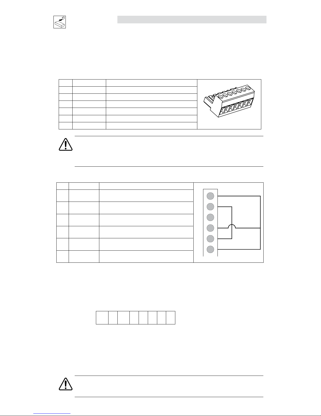
Installation and Connection
Connection of Two Safety Circuits with External +24V Supply
Pin Name Function
+
P1
P2
P3
P4
P5
P6
-
External
+24VDC
Safety Circuit
Input 1
Safety Circuit
Input 2
1 Bypass Voltage ISO 13849-1 Bypass Voltage (+24VDC)
2 Bypass COM ISO 13849-1 Bypass Common
3 Safety Status ISO 13849-1 Safety Status * 100mA max.
4 Safety Input1 ISO 13849-1 Safety Input 1 (+24VDC to Enable)
5 Safety COM ISO 13849-1 Safety Common
6 Safety Input2 ISO 13849-1 Safety Input 2 (+24VDC to Enable)
Page 30
28 L S94H201E_13426446_EN
Interface
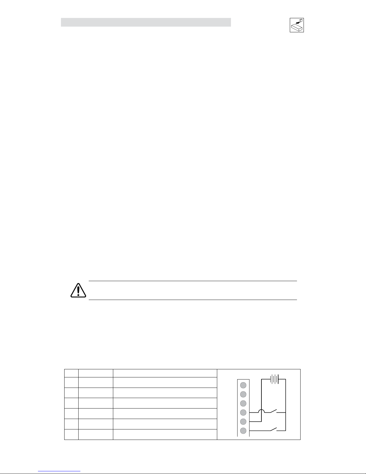
Evaluation and Testing of the ISO 13849-1 Safety Circuit
As part of the regulations for ISO 13849-1 safety circuit provision must be made for the user to periodically
test the safety circuits and that testing should be capable of identifying a single fault. The PositionServo
drive uses the safety status output (Pin 3) in conjunction with the display of the drive to allow the testing of
the safety circuits.
The safety status output becomes active to indicate partial or full enable of the safety input circuits 1 and
2. If safety input 1 or safety input 2 or both inputs are on then the safety status output will become active.
The safety status output must be connected to some visible indication for the operator to reference during
test of the circuit.
As well as being used to test the correct operation of the safety circuits the safety status output can be used
as an indicator that the drive has been placed in the fully shut down condition (all safety circuits off). For
example, if both Safety Inputs have been Deactivated, the Safety Status is also Deactivated. If one of the
Safety Inputs signals failed to call for a shutdown, or if one of the Safety Circuits failed to shut down, the
Safety Status signal remains Asserted to alert the operator to the problem.
The procedure for testing the ISO 13849-1 safety circuit and the identification of a single fault on the system
is given below. The safety status output should be connected to a visible indicator (such as a lamp or LED)
so the operator can interpret its condition.
NOTE
Customer must size load so as not to pull more than 100mA.
Safety Status Output Indication
Pin Name Function
P1
P2
P3
P4
P5
P6
Safety Output
Status Indication
+
-
External
+24VDC
Safety Circuit
Input 1
Safety Circuit
Input 2
1 Bypass Voltage ISO 13849-1 Bypass Voltage (+24VDC)
2 Bypass COM ISO 13849-1 Bypass Common
3 Safety Status ISO 13849-1 Safety Status *100mA max
4 Safety Input1 ISO 13849-1 Safety Input 1 (+24VDC to Enable)
5 Safety COM ISO 13849-1 Safety Common
6 Safety Input2 ISO 13849-1 Safety Input 2 (+24VDC to Enable)
Setting up the Drive in a Maintenance Mode:
WARNING!
During test of the ISO 13849-1 circuit, as laid out in this documentation the drive will
go to run (enabled) condition and motion from the motor may be generated. It is the
responsibility of the system designer to ensure the system remains in a safe condition
during the enclosed maintenance procedure.
Page 31

S94H201E_13426446_EN L 29
Interface
Guidance of setting up the drive to allow testing on the ISO 13849-1 circuit:
External Reference:
If the drive is getting its command signal from an external reference then Parameters should be set
accordingly.
From the Parameter Folder:
From the Digital IO Folder:
In this mode your external analog input will command movement. For safety purposes, measures should be
made to sure that velocity is at a minimum. From here you can proceed to the ISO 13849-1 Test Procedure.
Internal Reference:
If an Indexer program is used to operate the drive then it must contain a means of placing the drive into a
maintenance mode so that the ISO 13849-1 safety circuit can be safely tested. Responsibility lies with the
programmer on the safe implementation of a maintenance mode within the indexer program.
WARNING!
If no maintenance mode has been incorporated into the Indexer program then the Indexer
program must be erased prior to testing the ISO 13849-1 circuit. Save any code that is
required but has not previously been saved and then delete all code from the indexer
folder. Press the [Load W Source] button on the program toolbar to remove any residual
code from the drive memory.
The following truth table shows logical conditions for ISO 13849-1 circuits.
Safety Input 1 Safety Input 2 Safety Status Output Drive Display
*1
1 1 1 Run
1 0 1 F_EF
0 1 1 F_EF
0 0 0 F_EF
*1 – Drive display will change to condition shown on enable of the drive (Input A3 Enable)
Place Input A3, hardware enable in the deactivated state.
Test Procedure for ISO 13849-1 Safety Circuit:
Test
Step
Action Drive Display
Indication
Safety Status Output
Indication
Failed Test
Indication
1 Activate both safety
circuit inputs 1 & 2. Set
Input A3 to Enable
‘Run’ ‘Activated’ Trip on display (F_EF) = one of the safety inputs failed to
activate.
Status Output Deactivated = Both Safety Inputs Failed to
activate
2 Set Input A3 to Disable ‘Dis’ ‘Activated’ Status Output Deactivated = Both Safety Inputs Failed to
activate
3 Deactivate Safety
Input 1. Set Input A3
to Enable
’F EF’ ‘Activated’ No Trip on display (F_EF) = Safety Input 1 failed to deactivate.
Status Output Deactivated = Safety Input 2 Failed to activate
4 Activate Safety Input 1.
Set Input A3 to disable
‘Dis’ ‘Activated’ Status Output Deactivated = Both Safety Inputs Failed to
activate
Page 32

30 L S94H201E_13426446_EN
Interface
Test
Step
Action Drive Display
Indication
Safety Status Output
Indication
Failed Test
Indication
5 Deactivate Safety
Input 2. Set Input A3
to Enable
‘F EF’ ‘Activated’ No Trip on display (F_EF) = Safety Input 2 failed to deactivate.
Status Output Deactivated = Safety Input 1 Failed to activate
6 Set Input A3 to disable ‘Dis’ ‘Activated’ Status Output Deactivated = Both Safety Inputs Failed to
activate
7 Deactivate Safety
Input 1. Set Input A3
to Enable
‘F EF’ ‘Deactivated’ No Trip on display (F_EF) = Safety Inputs 1 & 2 failed to
deactivate.
Status Output Activated = Safety Input 1 or Safety Input 2
Failed to deactivate
This procedure will evaluate the following conditions:
a. All Circuits (safety inputs 1 & 2) working Correctly
b. Safety Input 1 failing to activate
c. Safety Input 1 failing to deactivate
d. Safety Input 2 failing to activate
e. Safety Input 2 failing to deactivate
f. Both Safety input 1 and 2 failing to activate
g. Both Safety input 1 and 2 failing to deactivate
Electrical Characteristics
Safety Input1, Safety Input2 and Safety Status are fully isolated from the rest of the drive circuits as shown
in the following diagram.
Safety Inputs Insulated, compatible with single-ended output (+24VDC)
Enable voltage range: 18 to 30VDC
Disable voltage range: 0 to 1.0 VDC
Input Impedance 6.8 kΩ
Safety Status Isolated Open Collector (Grounded Emitter)
Output Load Capability 100mA
Output Max Voltage 30VDC (Collector-Emitter)
Safety Status
Safety Input
2
Safety Input
1
Safety COM
SAFETY COM
SAFETY COM
SAFETY COM
6.8kΩ
6.8kΩ
1
1
1
2
2
2
3
3
3
4
4
4
A
A
A
C
C
C
E
E
E
K
K
K
Page 33

S94H201E_13426446_EN L 31
Interface
4.2 Digital I/O Details
4.2.1 Step & Direction/Master Encoder Inputs (P3, pins 1-4)
A master encoder with quadrature outputs or a step and direction pair of signals can be connected to the
PositionServo to control position in the external positioning operating mode. These inputs are optically
isolated from the rest of the drive circuits and from each other. Both inputs can operate from any voltage
source in the range of 5 to 24 VDC and do not require additional series resistors for normal operation.
CCW
CW
DIRECTION
STEP
S904
Timing Diagram for Step & Direction Signals
CCWCW
A
B
S905
Timing Diagram for Master Encoder Signals
Input type/output compatibility Insulated, compatible with single-ended or differential outputs
(5-24 VDC)
Max frequency (per input) 2 MHz
Min pulse width (negative or positive) 500nS
Input impedance 700 Ω (approx)
MA+/STEP+
MB+/DIR+
MA-/STEP-
MB-/DIR-
600
Ω
100
Ω
5.6V
S906
Master Encoder Step & Direction Input Circuit
Differential signal inputs are preferred when using Step and Direction. Single ended inputs can be used but
are not recommended. Sinking or sourcing outputs may also be connected to these inputs. The function of
these inputs “Master Encoder” or “Step and Direction” is software selectable. Use the MotionView set up
program to choose the desirable function.
Page 34

32 L S94H201E_13426446_EN
Interface
4.2.2 Buffered Encoder Output (P3, pins 7-12)
There are many applications where it is desired to close the feedback loop to an external device. This
feature is built into the PositionServo drive and is referred to as the “Buffer Encoder Output”. If a motor with
encoder feedback is being used, the A+, A-, B+, B-, Z+ and Z- signals are directly passed through the drive
through pins 7-12 with no delays, up to a speed of 2MHz. If a motor with resolver feedback is being used
a minimal encoder feedback is transmitted. The default resolution of the simulated encoder is 1024 pulses
per revolution, pre-quad. If a different resolution is desired refer to section 5.3.19 “Resolver Tracks”. There
is a small additional delay when using a resolver. With Encoder pass through the delay is approximately
100nS; with Resolver pass through, the delay is approximately 62uS. Refer to Note 1 in section 4.1.7.
4.2.3 Digital Outputs
There are a total of five digital outputs (“OUT1” - “OUT4” and “RDY”) available on the PositionServo drive.
These outputs are accessible from the P3 connector. Outputs are open collector/emitter and are fully
isolated from the rest of the drive circuits as shown in the figures below. These outputs can be used by the
drive’s internal User Program or they can be configured as Special Purpose outputs. When used as Special
Purpose, each output (OUT1-OUT4) can be assigned to one of the following functions:
• Not assigned
• Zero speed
• In-speed window
• Current limit
• Run-time fault
• Ready
• Brake (motor brake release)
Note that if an output is assigned as a Special Purpose Output then that output can not be utilized by the
User Program. The “RDY” Output has a fixed function, “ENABLE”, that will become active when the drive is
enabled and the output power transistors become energized.
Digital outputs electrical characteristics
Circuit type Isolated open collector/emitter
Digital outputs load capability 100mA
Digital outputs Collector-Emitter max voltage 30V
The digital outputs have a typical 1 volt leakage. Apply the appropriate relays based on the application. The
outputs on the drive can be wired as either sinking (NPN) or sourcing (PNP), as illustrated herein.
NPN Sinking
OUT 1-C
Gnd
+24V
43
44
45
46
OUT 1-E
OUT 2-C
OUT 2-E
PNP Sourcing
OUT 1-C
Gnd
+24V
43
44
45
46
OUT 1-E
OUT 2-C
OUT 2-E
mb101 mb102
Page 35

S94H201E_13426446_EN L 33
Interface
4.2.4 Digital Inputs
IN_Ax, IN_Bx, IN_Cx (P3.26-30, P3.31-35, P3.36-40)
The PositionServo drive has 12 optically isolated inputs. These inputs are compatible with a 5 - 24V voltage
source. No additional series resistors are needed for circuit operation. The 12 inputs are segmented into
three groups of 4, Inputs A1 - A4, Inputs B1 - B4, and Inputs C1 - C4. Each group, (A, B and C) have their
own corresponding shared COM terminal, (ACOM, BCOM and CCOM). Each group or bank can be wired as
sinking or sourcing. Refer to the PNP Sourcing and NPN Sinking wiring examples herein. All inputs have a
separate software adjustable de-bounce time. Some of the inputs can be set up as Special Purpose Inputs.
For example, inputs A1 and A2 can be configured as hardware limit switch inputs, input A3 is always set up
as an Enable input and input C3 can be used as a registration input. Refer to the PositionServo Programming
Manual for more detail.
For the registration input (C3), the registration time is 3µs for an encoder and 7µs for a resolver.
PNP Sourcing
Digital inputs circuit.
Gnd
+24V
27
IN_A1
26
28
IN_A2
IN_A_COM
2.4 k
2.4 k
mb103
NPN Sinking
Digital inputs circuit.
Gnd
+24V
27
IN_A1
26
28
IN_A2
IN_A_COM
2.4 k
2.4 k
mb104
Page 36

34 L S94H201E_13426446_EN
Interface
4.3 Analog I/O Details
4.3.1 Analog Reference Input
AIN1+, AIN1- (P3.24 and P3.25)
The analog reference input can accept up to a ±10V analog signal across AIN1+ and AIN1-. The maximum
limit with respect to analog common (ACOM) on each input is ±18VDC. The analog signal will be converted
to a digital value with 12 bit resolution (11-bit plus sign). This input is used to control speed or torque of the
motor in velocity or torque mode. The total reference voltage as seen by the drive is the voltage difference
between AIN1+ and AIN1-. If used in single-ended mode, one of the inputs must be connected to a voltage
source while the other one must be connected to Analog Common (ACOM). If used in differential mode, the
voltage source is connected across AIN1+ and AIN1- and the driving circuit common (if any) needs to be
connected to the drive Analog Common (ACOM) terminal. Refer to the External Reference and Single-Ended
Configuration wiring examples below.
Reference as seen by drive: Vref = (AIN1+) - (AIN1-) and -10V < Vref < +10V
External Reference
(Dierential Conguration)
ACOM
Analog Command Output
Analog Command Return
ACOM
P3.24
P3.25
P3.22
AIN-
AIN+
PostionServo
Drive
940 Servo Drive
+
-
Analog input +
Analog input -
Analog Input
Motion
Controller
mb105
Single-ended Configuration
ACOM
AOut
P3.20
P3.21
P3.22
AIN-
AIN+
PositionServo
Drive
ACOM
As the dancer arm goes up and down
a 0 - 10 volt signal is transmitted
to the PositionServo Drive.
+
-
mb106
AIN2+, AIN2- (P3.20 and P3.21)
The analog reference input can accept up to a ±10V analog signal across AIN2+ and AIN2-. The maximum
limit with respect to analog common (ACOM) on each input is ±18VDC. The analog signal will be converted
to a digital value with 12 bit resolution (11-bit plus sign). This input is available to the User’s program. This
input does not have a predefined function.
Page 37

S94H201E_13426446_EN L 35
Interface
4.3.2 Analog Output
AO (P3.23)
The analog output is a single-ended signal (with reference to Analog Common (ACOM) which can represent
the following motor data:
• Not Assigned • Phase R Current • Iq Current
• RMS Phase Current • Phase S Current • Id Current
• Peak Phase Current • Phase T Current
• Motor Velocity
Motor phase U, V and W correspond to R, S and T respectively.
MotionView Setup program can be used to select the signal source for the analog output as well as its
scaling.
If the output function is set to “Not Assigned” then the output can be controlled directly from user’s program.
Refer to the PositionServo Programming Manual for details.
STOP!
Upon application of power to the PositionServo, the Analog Output supplies -10VDC
until bootup is complete. Once bootup is complete, the Analog Output will supply the
commanded voltage.
4.4 Communication Interfaces
4.4.1 Ethernet Interface (standard)
Programming and diagnostics of the drive are performed over the standard Ethernet communication port.
The drive’s IP address is addressable from the drive’s front panel display. The interface supports both 100
BASE-TX as well as 10 BASE-T. This configuration allows the user to monitor and program multiple drives
from MotionView. Refer to section 5.4.1 for PC configuration information.
4.4.2 RS485 Interface (option)
PositionServo drives can be equipped with an RS485 communication interface option module (E94ZARS41)
that is optically isolated from the rest of the drive’s circuitry. The option module can be used for
communications to the drive as a Modbus RTU slave or over UPPP protocol. The PositionServo drive
supports 7 different baud rates from 2400 to 115200. As a Modbus RTU slave, drives are addressable at
up to 247 addresses (repeaters are required above 31 devices on the network). The factory setting for the
baud rate is 38,400 with a node address of “1”. The drive’s address and baud rate can be set from the front
panel of the drive or in MotionView.
RS485 Interface Pin Assignments
Pin Name Function
1
2
3
TXA
TXB
ICOM
1
2
3
1 ICOM Isolated Common
2 TXB Transmit B(+)
3 TXA Transmit A(-)
Page 38

36 L S94H201E_13426446_EN
Interface
4.4.3 Modbus RTU Support
The RS485 interface is configured through the MotionView program. When configured for Modbus operation,
the baud rate for RS485 is set using the parameter “RS485 baud rate”. Modbus RTU requires 8 data
bits. The Modbus RTU slave interface protocol definitions can be found on the MotionView CD in “Product
Manuals”, P94MOD01.
NOTE
Only one communication option module (RS485, CANopen, DeviceNet or PROFIBUS DP)
can be installed in the Option Bay 1 at a time. The COMM modules can be exchanged out
and replaced with another of a different type. The Ethernet interface supports Modbus
TCP/IP and EtherNet/IP.
4.4.4 CANopen Interface
An optional CANopen communication module (E94ZACAN1) is available for the PositionServo drive. Installed
in Option Bay 1 as P21, the CANopen module is optically isolated from the rest of the drive’s circuitry. The
3-pin CANopen module is for HW/SW 1A10 and the 5-pin CANopen module is for HW/SW 1B10 or higher.
Refer to the PS CANopen Reference Guide (P94CAN01) for more information.
CANopen Interface Pin Assignments
Pin Name Function Pin Name Function
1 ICOM Isolated Common 1 NC No connection
2 CAN L CAN Bus Low 2 CAN L CAN Bus Low
3 CAN H CAN Bus High 3 Shield
4 CAN H CAN Bus High
5 NC No connection
1
2
3
CAN H
CAN L
ICOM
1
2
3
NC
CAN L
Shield
CAN H
NC
1
2
3
4
5
4.4.5 DeviceNet Interface
An optional DeviceNet communication module (E94ZADVN1) is available for the PositionServo drive. Installed
in Option Bay 1 as P23, the DeviceNet module is optically isolated from the rest of the drive’s circuitry. The
DeviceNet module is a 5-pin quick connect terminal block. Refer to the PS DeviceNet Communications
Reference Guide (P94DVN01) for detailed information.
DeviceNet Interface Pin Assignments
Pin Name Function
V-
CAN Lo
w
Shield
CAN High
V+
1
2
3
4
5
1 V- 0V
2 CAN L CAN Bus Low (Negative data line)
3 Shield
4 CAN H CAN Bus High (Positive data line)
5 V+ 11-25VDC power supply
Page 39

S94H201E_13426446_EN L 37
Interface
4.4.6 PROFIBUS DP Interface
An optional PROFIBUS DP communication module (E94ZAPFB1) is available for the PositionServo drive.
Installed in Option Bay 1 as P24, the PROFIBUS DP module is optically isolated from the rest of the drive’s
circuitry. The PROFIBUS module is a female DB-9 connector. Refer to the PS PROFIBUS Communications
Reference Guide (P94PFB01) for detailed information.
Pin Name Function
1
5
9
6
1 Shield Cable Shield Connection
2 N/C No Connection
3 RxD/TxD-P Data Line B (Red)
4 N/C No Connection
5 DGND Data Ground
6 +5V 5V Output Supply
7 N/C No Connection
8 RxD/TxD-N Data Line A (Green)
9 N/C No Connection
4.5 Motor Selection
The PositionServo drive is compatible with many 3-phase AC synchronous servo motors. MotionView
OnBoard is equipped with a motor database that contains hundreds of motors for use with the PositionServo
drive. If the desired motor is in the database, no data is needed to set it up. Just select the motor and click
“OK”. However, if the motor is not in the database, it can still be used, but some electrical and mechanical
data must be provided to create a custom motor profile. The auto-phasing feature of the PositionServo drive
allows the user to correctly determine the relationship between phase voltage and hall sensor signals or
resolver offset, eliminating the need to determine feedback orientation by other means.
4.5.1 Motor Connection
Motor phase U, V, W (or R, S, T) are connected to terminal P7. It is very important that motor cable shield is
connected to Earth ground terminal (PE) or the drive’s case. The motor’s encoder/resolver feedback cable
must be connected to terminal P4.
4.5.2 Motor Over-Temperature Protection
NOTE
The PositionServo does not provide motor over-temperature protection. The user may
connect a KTY motor thermal sensor to the drive as detailed in section 4.1.1 and this
paragraph, 4.5.2, if necessary to satisfy NEC requirements.
If using a motor equipped with an encoder and PTC thermal sensor, the encoder feedback cable will have
flying leads exiting the P4 connector to be wired to the P7.1 (T1) and P7.2 (T2) terminals. If using a motor
equipped with a Resolver and a PTC sensor, the thermal feedback is passed directly to the drive via the
resolver 9-pin D shell connector.
Use parameter “Motor PTC cut-off resistance” (section 5.3.10) to set the resistance that corresponds to
maximum motor allowed temperature. The parameter “Motor temperature sensor” must also be set to
ENABLE. If the motor doesn’t have a PTC sensor, set this parameter to DISABLE. This input will also work
with N.C. thermal switches which have only two states; Open or Closed. In this case “Motor PTC cut-off
resistance” parameter can be set to the default value.
Page 40

38 L S94H201E_13426446_EN
Parameters
5 Parameters
The PositionServo drive has many programmable features accessible via the universal software MotionView.
This chapter covers the drive’s programmable features and parameters in the order they appear in the
Parameter Tree of MotionView. Programmable parameters are divided into folders. Each folder contains one
or more user adjustable parameters.
Parameter (Node) Tree
All drives can execute a User Program in parallel with motion. Motion can be specified by variety of sources
and in three different modes:
Torque Velocity Position
In Torque and Velocity mode the reference can be taken from Analog Input AIN1 or from the User Program
by setting a particular variable (digital reference). In Position mode, the reference can be taken from MA/MB
master encoder/step and directions inputs (available in terminal P3) or from trajectory generator. Access to
the trajectory generator is provided through the User Program’s motion statements, MOVEx and MDV. Refer
to the PositionServo Programming Manual for details on programming. Whether the reference comes from
an external device, (AIN1 or MA/MB ) or from the drives internal variables (digital reference and trajectory
generator) will depend on the parameter settings.
Page 41

S94H201E_13426446_EN L 39
Parameters
5.1 Drive Identification
At the top of the Node Tree, click the Drive name [E94P 240V 04Amp ...]. The drive ID string, device
family, firmware revision, vector processor revision, hardware revision, MotionView OnBoard revision, motor
database revision, indexer compiler revision, serial number, drive name and group ID are displayed as
illustrated herein. With the exception of the Drive Name and Group ID, the drive identification parameters
are fixed and provided for information only.
The drive identifier (E94P 240V 04Amp [192.168.124.120] : STOPPED) in the node tree consists of three
segments: the drive’s name, the drive’s IP address and the status of the Indexer Program.
Drive name: E94P 240V 04Amp
Drive IP address: 192.168.124.120
Indexer program status: STOPPED (indexer program is stopped)
RUNNING (indexer program is running)
The drive identifier also indicates the status of the drive. When the drive identifier in the node tree is
highlighted in green, the drive is enabled. When the drive identifier is gray, the drive is disabled.
5.1.1 Drive Name
To assign a name to the drive click in the box adjacent to Drive Name. A alpha-numeric name may be
entered to identify the drive.
5.1.2 Group ID
The Group ID feature allows the user to group PositionServo drives together via an Ethernet network. When
used with the SEND and SENDTO command, drives in the same group can share and update variables. Group
ID Numbers can be set between 0 and 32767. See statements SEND and SENDTO for further explanations.
Page 42

40 L S94H201E_13426446_EN
Parameters
5.2 Motor
The motor folder displays the data for the currently selected motor. A motor may be selected from the
database or a custom motor may be configured.
5.2.1 Motor Setup
Select the [Motor] folder in the right-hand “Parameter View Window”. To select a new motor click the
[Change Motor] button. When [Change Motor] is selected, the Motor Database dialog box will open. Select
the Motor Type from the node tree in the left-hand window.
NOTE: The drive must be is DISABLED (display: “diS”) to setup a new motor.
To make a new motor selection:
• Click [Change Motor] in the Parameter View Window.
• Select motor Vendor and Motor Model from the pull down menus.
• Click [Update Drive] to complete the motor selection, dismiss the dialog box and return to MotionView
OnBoard’s main program.
• If using a motor not listed in the current motor database, select [Create Custom] and refer to section
5.2.2 “Using a Custom Motor”.
Page 43

S94H201E_13426446_EN L 41
Parameters
NOTE
To help prevent the motor from drawing to much current and possibly overheating it is recommended that
the drive’s “Current Limit” be checked against the motors “Nominal Phase Current” and set accordingly.
5.2.2 Using a Custom Motor
Follow these instructions to load a custom motor from a file or create a new custom motor. From the
Parameter tree select the [Motor] folder. From the Parameter view window select [Change Motor].
• With the Motor Database dialog box open, Click [Custom Motor] under the Motor Type from the lefthand window: Synchronous or Induction/Asynchronous.
• Input the Motor data manually or from a previously saved motor file. To load motor data from a file
click [Open file], select file path and click [OK] to open.
• To add this new custom file to your computer’s hard drive, click [Save File], select file path and click
[OK] to save.
• To load this file to the drive, click [Update Drive].
• When selecting [OK] for a custom motor, a dialog box will appear prompting for a decision to
perform/not perform “Autophasing” (refer to section 5.2.4).
5.2.3 Creating Custom Motor Parameters
STOP!
Use extreme caution when entering custom parameters! Incorrect settings may damage the drive or
motor! If unsure of the settings, refer to the materials distributed with the motor, or contact the motor
manufacturer for assistance.
1. Enter custom motor data in the Motor Parameters dialog fields. Complete all sections of dialog:
Electrical, Mechanical, Feedback and Motor Gain Scaling.
NOTE
If unsure of the motor halls order and encoder channels A and B relationship, leave “B leads A for
CW”, “Halls order” and “inverted” fields as they are. Use Autophasing (section 5.2.4) to set them
correctly.
2. Enter motor model and vendor in the top edit boxes. Motor ID cannot be entered, this is set to
0 for custom motors. Likewise, if unsure of resolver offset and direction of rotation leave at
default and correct using the Autophasing.
3. Click [Save File] button and enter filename without extension. The default extension .cmt will be
given when you click OK on file dialog box.
Page 44

42 L S94H201E_13426446_EN
Parameters
NOTE
Save the file even if the autophasing feature will be used and some of the final parameters are not
known. After autophasing is completed, the corrected motor file can be updated before loading it to
memory.
4. Click [Close] to exit from the Motor Parameters dialog.
5. MotionView will prompt to autophase/not autophase the custom motor. Answer [No] to cancel
without applying the changes made in the Motor database window. Answer [Yes] and the motor
dialog will be dismissed and the drive will start the autophasing sequence. Refer to section
5.2.4, Autophasing.
6. If [Yes] is selected, the same motor selection dialog box will be displayed after autophasing is
complete. For motors with incremental encoders, the fields “B leads A for CW”, “Halls order”
and “inverted” will be assigned correct values. For motors with resolvers, the fields “Offset in
degree” and “CW for positive” will be assigned correct values.
7. Click [Save File] to save the custom motor file and then click [Update Drive] to exit the dialog
box and load the data to the drive.
5.2.4 Autophasing
The Autophasing feature determines important motor parameters when using a motor that is not in
MotionView’s database. For motors equipped with incremental encoders, Autophasing will determine the
Hall order sequence, Hall sensor polarity and encoder channel relationship (B leads A or A leads B for CW
rotation). For motors equipped with resolvers, Autophasing will determine resolver angle offset and angle
increment direction (“CW for positive”).
To perform autophasing:
1. Complete the steps in “Creating custom motor parameters”. If the motor file to be autophased
already exists, simply load it as described under “Using a custom motor”.
2. Make sure that the motor’s shaft is not connected to any mechanical load and can freely rotate.
STOP!
Autophasing will energize the motor and will rotate the shaft. Make sure that the motor’s shaft is not
connected to any mechanical load and can freely and safely rotate.
3. Make sure that the drive is not enabled.
4. For Encoder it is not necessary to edit the field “Hall order” and check boxes “inverted” and “B
leads A for CW” as these values are ignored for autophasing. For Resolver it is not necessary to set
“Offset in degree” and “CW for positive”.
5. Click [Update Drive] to dismiss motor selection dialog. MotionView responds with the question “Do
you want to perform autophasing?”
6. Click [OK]. A safety reminder dialog appears. Verify that it is safe to run the motor then click [Yes]
and wait until autophasing is completed.
NOTE
If a problem occurs with the motor, hall sensor or resolver connections, MotionView will send an error
message. The source of the error is commonly the power, shield and ground terminations or the use
of an improper cable. Correct the wiring problem(s) and repeat steps 1 - 6.
If the error message repeats, exchange motor phases U and V (R and S) and repeat. If problems
persist, contact the factory.
7. If autophasing is completed with no error then MotionView will return to the motor dialog box. For
motors with incremental encoders, the parameter field “Hall order” and the check boxes “inverted”,
“B leads A for CW” will be filled in with correct values. For resolver equipped motors, fields “Offset ”
and “CW for positive” will be correctly set.
Page 45

S94H201E_13426446_EN L 43
Parameters
8. Click [Save File] to save the completed motor file (use same filename as the initial data in step 1).
Click [Update Drive] to load the motor data to the drive.
5.2.5 Custom Motor Data Entry
A Custom Motor file is created by entering motor data into the “Motor Parameters” dialog box. This box
is divided up into four sections: Electrical constants, Mechanical constants, Feedback and Gain Scaling.
Parameter Type Synchronous Motor Asynchronous (Induction) Motor
Identification Vendor, Motor Model, ID Vendor, Motor Model, ID
Electrical Kt, Ke, Lm, Rm, I
RMS
, Nominal V
BUS
,
# of poles
Cos f, f
Base
, Lm, Rm, I
RMS
, Nominal V
BUS
,
# of poles
Feedback Primary feedback, Resolver Offset Resolver FB, Encoder PPR before quad,
B leads A CW
Motor Gain Scaling Velocity P-gain, Velocity I-gain,
Gain Scaling
Velocity P-gain, Velocity I-gain,
Gain Scaling
Mechanical Jm, Vel
MAX
Jm, Vel
NOMINAL
, Vel
MAX
When creating a custom motor, input the value of all parameters listed for the specific motor type. All
entries are mandatory except motor inertia (Jm). Enter a value of 0 for the motor inertia if the actual value
is unknown.
5.2.5.1 Electrical & Mechanical Constants
Motor Torque Constant (Kt)
Enter the value and select proper units from the drop-down list.
NOTE
Round the calculated result to 3 significant places.
Motor Voltage Constant (Ke)
The program expects Ke to be entered as a phase-to-phase Peak voltage. If you have Ke as an RMS value,
multiply this value by 1.414 for the correct Ke Peak value.
Phase-to-phase winding Inductance (Lm)
This must be set in millihenries (mH). The phase-to-phase winding Inductance (L) will typically be between
0.1 and 200.0 mH.
NOTE
If the units for the phase-to-phase winding Inductance (L) are given in micro-henries
(µH), then divide by 1000 to get mH.
Phase-to-phase winding Resistance (Rm) in Ohms
This is also listed as the terminal resistance (Rt). The phase-to-phase winding Resistance (R) will typically
be between 0.05 and 200 Ohms.
Nominal phase current (RMS Amps)
Nominal continuous phase current rating (In) in Amps RMS. Do not use the peak current rating.
Page 46

44 L S94H201E_13426446_EN
Parameters
NOTE
If the phase current rating is not given, use this equation to obtain the nominal continuous
phase-to-phase winding current:
In = Continuous Stall Torque / Motor Torque Constant (Kt)
The same force x distance units must be used in the numerator and denominator in the equation above. If
torque (T) is expressed in units of pound-inches (lb-in), then Kt must be expressed in pound-inches per Amp
(lb-in/A). Likewise, if T is expressed in units of Newton-meters (N-m), then units for Kt must be expressed
in Newton-meters per Amp (N-m/A).
Example:
Suppose that the nominal continuous phase to phase winding current (In) is not given. Instead, we
look up and obtain the following:
Continuous stall torque T = 3.0 lb-in
Motor torque constant Kt = 0.69 lb-in/A
Dividing, we obtain:
In = 3.0 lb-in / 0.69 lb-in/A =4.35 (A)
Our entry for (In) would be 4.35.
Note that the torque (lb-in) units are cancelled in the equation above leaving just Amps (A). We would
have to use another conversion factor if the numerator and denominator had different force x distance
units.
Nominal Bus Voltage (Vbus)
The Nominal Bus Voltage can be calculated by multiplying the Nominal AC mains voltage supplied by 1.41.
When using a model with the suffix “S1N” where the mains are wired to the “Doubler” connection, the
Nominal Bus Voltage will be doubled.
Example:
If the mains voltage is 230VAC, Vbus = 230 x 1.41 = 325V
This value is the initial voltage for the drive and the correct voltage will be calculated dynamically
depending on the drive’s incoming voltage value.
Number of Poles
This is a positive integer number that represents the number of motor poles, normally 2, 4, 6 or 8.
Rotor Moment of Inertia (Jm)
From motor manufacturer or nameplate.
NOTE
Round the calculated result to 3 significant places.
5.2.5.2 For Incremental Encoder - Equipped Motors Only
Encoder Line Count
The encoders for servomotors normally have line counts of 1000, 1024, 2000, 2048, 4000, or 4096. The
Encoder Line Count is pre-quadrature and a positive integer.
Halls Order
Each hall signal is in phase with one of the three phase-phase voltages from the motor windings. Hall order
number defines which hall sensor matches which phase-phase voltage. Motor phases are usually called
R-S-T or U-V-W or A-B-C. Phase-Phase voltages are called Vrs, Vst, Vtr. Halls are usually called HALL-A,
HALL-B, HALL-C or just Halls 1, 2, 3. A motor’s phase diagram is supplied by motor vendor and usually
can be found in the motor data sheet or by making a request to the motor manufacturer. A sample phase
diagram is illustrated in Figure S912.
Page 47

S94H201E_13426446_EN L 45
Parameters
S912
The Halls Order is obtained as follows:
1. Look at the “Vrs” Output Voltage and determine the Hall Voltage that is lined up with (or in phase
with) this voltage. To determine which Hall Voltage is in phase with the Vrs Output Voltage draw
vertical lines at those points where it crosses the horizontal line (zero). The dashed lines at the zero
crossings (above) indicate that Hall B output is lined up with (and in phase with) the Vrs Output
Voltage.
2. Look at the “Vst” Output Voltage. Determine which Hall Voltage is in phase with this Voltage. Per
Figure S912, the Hall C output is in phase with the Vst Output Voltage.
3. Look at the “Vtr” Output Voltage. Determine which Hall Voltage is in phase with this Voltage. Per
Figure S912, the Hall A output is in phase with the Vtr Output Voltage.
NOTE
If hall sensors are in phase with the corresponding phase voltage but are inverted 180
degrees (hall sensor waveform edge aligns with the phase-phase voltage waveform
but the positive hall sensor cycle matches the negative phase-phase waveform or visaversa), you must check the “Inverted” check box.
4. The phases that correspond to the Vrs, Vst and Vtr voltages are Hall B then Hall C then Hall A or
Halls number 2 then 3 then 1. Referring to the following table, we find that 2-3-1 sequence is Halls
Order number 3. We would then enter 3 for the Halls Order field in the motor dialog box.
Hall Order Numbers for Different Hall Sequences
Halls Order Hall Sequence
0 1-2-3
1 1-3-2
2 2-1-3
3 2-3-1
4 3-1-2
5 3-2-1
NOTE
Each Hall Voltage is in phase with one and only one Output Voltage.
Page 48

46 L S94H201E_13426446_EN
Parameters
B leads A for CW
This is the encoder phase relationship for CW/CCW shaft rotation. When you obtain the diagram for your
motor phasing similar to shown above, it’s assumed by the software that the motor shaft rotates CW when
looking at the rear of the motor. For that rotation Encoder phase A must lead phase B. If it does, leave the
check box unchecked. Otherwise (if B leads A), check B leads A in the CW box.
NOTE
The reference for direction of rotation is from the rear of the motor.
NOTE
This parameter does not reverse the direction of motor rotation. It is used to setup the
motor commutation. See “Rotation Direction” in the Parameters menu to reverse the
direction of forward rotation.
5.2.5.3 For Resolver Equipped Motors Only
If parameter “Resolver” is checked, following parameters appear on the form:
Offset in degree (electrical)
This parameter represents offset between resolver’s “0 degree” and motor’s windings “0 degree”.
CW for positive
This parameter sets the direction for positive angle increment.
“Offset in degree” and “CW for positive” will be set during Auto-Phasing of the motor.
Page 49

S94H201E_13426446_EN L 47
Parameters
5.3 Parameters
Parameters List - Top
Parameters List - Bottom
Page 50

48 L S94H201E_13426446_EN
Parameters
5.3.1 Drive Mode
The PositionServo has 3 operating mode selections: Torque, Velocity and Position.
For Torque and Velocity modes the drive will accept an analog input voltage on the AIN1+ and AIN1- pins
of P3 (refer to section 4.3.1). This voltage is used to provide a torque or speed reference.
For Position mode the drive will accept step and direction logic signals or a quadrature pulse train on pins
P3.1- P3.4.
5.3.1.1 Torque Mode
In torque mode, the servo control provides a current output proportional to the analog input signal at input
AIN1, if parameter “Reference” is set to “External”. Otherwise the reference is taken from the drive’s
internal variable. (Refer to the PositionServo Programming Manual for details)
For analog reference “Set Current”, (current the drive will try to provide), is calculated using the following
formula:
Set Current(A) = Vinput(Volt) X Iscale (A/Volt)
where:
• Vinput is the voltage at analog input
• Iscale is the current scale factor (input sensitivity) set by the Analog input
(Current Scale) parameter (section 5.5.4).
5.3.1.2 Velocity Mode
In velocity mode, the servo controller regulates motor shaft speed (velocity) proportional to the analog input
voltage at input AIN1, if parameter “Reference” is set to “External”. Otherwise the reference is taken from
the drive’s internal variable. Refer to the PositionServo Programming Manual for details.
For analog reference, Target speed (set speed) is calculated using the following formula:
Set Velocity (RPM) = Vinput (Volt) x Vscale (RPM/Volt)
where:
• Vinput is the voltage at analog input (AIN1+ and AIN1-)
• Vscale is the velocity scale factor (input sensitivity) set by the Analog input
(Velocity scale) parameter (section 5.5.5).
5.3.1.3 Position Mode
In this mode the drive reference is a pulse-train applied to P3.1-4 terminals, if the parameter “Reference”
is set to “External”. Otherwise the reference is taken from the drive’s internal motion commands. (Refer to
the PositionServo Programming Manual for details).
P3.1-4 inputs can be configured for two types of signals: step and direction and Master encoder quadrature
signal. Refer to section 4.2.1 for details on these inputs connections. Refer to section 6.4 for details about
positioning and gearing.
When the Reference is set to Internal, the drives reference position, (theoretical or Target position), is
generated by trajectory generator. Access to the trajectory generator is provided by motion statements,
MOVEx and MDV, from the User Program. Refer to the PositionServo Programming Manual for details.
5.3.2 Reference
The REFERENCE setting selects the reference signal being used by the drive. This reference signal can be
either External or Internal. An External Reference can be one of three types, an Analog Input signal, a Step
and Direction Input or an Input from a external Master Encoder. The Analog Input reference is used when the
drive is either in torque or velocity mode. The Master Encoder and Step and Direction reference is used when
the drive is in position mode. An Internal Reference is used when the motion being generated is derived from
drive’s internal variable(s), i.e., User Program. Refer to the PositionServo Programming Manual.
Page 51

S94H201E_13426446_EN L 49
Parameters
5.3.3 Drive PWM Frequency
This parameter sets the PWM carrier frequency. Frequency can be changed only when the drive is disabled.
Maximum overload current is 300% of the drive rated current when the carrier is set to 8kHz. It is limited
to 250% at 16kHz.
5.3.4 Current Limit
The Current Limit setting determines the nominal currents, in amps RMS per phase, that output to the motor
phases. To prevent the motor from overloading, this parameter is usually set equal to the motor nominal (or
rated) phase current. The Current Limit is set equal to the nominal motor phase current by default when a
motor model is selected.
5.3.5 To Change Current Limits
To modify/overwrite the Current Limit place a checkmark in the box. If this box is checked, the parameters
“Current limit”, “8 kHz peak current limit” and “16 kHz peak current limit” can be overwritten. To prevent
the motor from overloading, the “current Limit”, “8 kHz peak current limit” and “16 kHz peak current limit”
shall be set to values no higher than the corresponding current limits of the motor in use.
5.3.6 Peak Current Limit (8 kHz and 16 kHz)
Peak Current Limit sets the motor RMS phase current that is allowed for up to 2 seconds. After this two
second limit, the drive output current to motor will be reduced to the value set by the Current Limit parameter.
When the motor current drops below nominal current for two seconds, the drive will automatically re-enable
the peak current level. This technique allows for high peak torque on demanding fast moves and fast start/
stop operations with high regulation bandwidth. If 8 kHz is used for Drive PWM frequency, use the parameter
8 kHz Peak Current Limit, otherwise, use 16 kHz Peak Current Limit.
The Peak Current Limit is set equal to 2.5 times the nominal motor phase current by default when a motor
model is selected. The maximum of 3 times nominal motor phase current can be obtained at 8kHz. To
prevent motor from overloading, the Peak Current Limit shall be set no higher than the maximum motor
current. Otherwise, the motor may be damaged due to overheating. To modify this limit, refer to section
5.3.5.
5.3.7 Accel/Decel Limits (velocity mode only)
The Accel setting determines the time the motor takes to ramp to a higher speed. The Decel setting
determines the time the motor takes to ramp to a lower speed. If the Enable Accel/Decel Limits is set to
[Disable], the drive will automatically accelerate and decelerate at maximum acceleration limited only by the
current limit established by the Peak Current Limit and Current Limit settings. This parameter is only utilized
when the drive is set to Velocity mode (refer to 5.3.1).
5.3.8 Fault Reset
Fault Reset selects the type of action required to reset the drive after a FAULT condition has been generated
by the drive. On Disable clears the fault when the drive is disabled. This is useful if you have a single drive
and motor connected in a single drive system. The On Enable option clears the fault when the drive is
re-enabled. Choose On Enable if you have a complex servo system with multiple drives connected to an
external controller. This makes troubleshooting easier since the fault will not be reset until the drive is reenabled. Thus, a technician can more easily determine which component of a complex servo system has
caused the fault.
Page 52

50 L S94H201E_13426446_EN
Parameters
5.3.9 Motor Temperature Sensor
This parameter enables / disables motor over-temperature detection. It must be disabled if the motor PTC
sensor is not wired to either P7.1-2 or to the resolver feedback input (P4 or P11).
5.3.10 Motor PTC Cutoff Resistance
This parameter sets the cut-off resistance of the PTC that defines when the motor reaches the maximum
allowable temperature. Refer to section 4.5.2 for details on how to connect the motor’s PTC.
5.3.11 Regen Duty Cycle
This parameter sets the maximum duty cycle for the brake (regeneration) resistor. This parameter can be
used to prevent brake resistor overload. Use the following formula to calculate the maximum value for this
parameter. If this parameter is set equal to the calculated value, the regeneration resistor is most effective
without overload. One may set this parameter with a value smaller than the calculated one if the drive will
not experience over voltage fault during regeneration.
D = P * R / (Umax)
2
* (1/D
application
) * 100%
Where:
D (%) regeneration duty cycle
Umax (VDC) bus voltage at regeneration conditions
U
max
= 390 VDC for 120/240 VAC drives and 770 VDC for 400/480 VAC drives.
R (Ohm) regeneration resistor value
P (W) regeneration resistor rated power
D
application
(%) application duty cycle. For the continuous regeneration applications, use Dapplication = 1. For
the intermittent regeneration applications, use Dapplication = t/T, where t is the duration when
regeneration is needed and T is the time interval between two regenerations. Both t and T must use
the same time unit, e.g., seconds
t, regeneration
T-t, regeneration
is not needed
T
If calculation of D is greater than 100% set it to 100% value. If calculation of D is less than 10% then
resistor power rating is too low. For more information refer to the PositionServo Dynamic Braking Manual
(G94BR01).
Minimum Required Dynamic Braking Resistance
Drive Model DB Minimum Resistance (Ω)
E94_180T2N~~ 15
E94_080S2F~~, E94_080Y2N~~,
E94_100S2F~~, E94_100Y2N~~
20
E94_120Y2N 30
E94_020S1N~~, E94_020S2F~~,
E94_020Y2N~~, E94_040S1N~~,
E94_040S2F~~, E94_040Y2N~~
40
E94_090T4N~~ 45
E94_040T4N~~, E94_050T4N~~, E94_060T4N~~ 75
E94_020T4N~~ 150
Page 53

S94H201E_13426446_EN L 51
Parameters
5.3.12 Master Encoder Input Type (position mode only)
This parameter sets the type of input for position reference the drive expects to see. Signal type can be step
and direction [Step & Direction] type or quadrature pulse-train [Master Encoder]. Refer to section 4.2.1 for
details on these inputs.
5.3.13 Master Encoder - System to Master Ratio
This parameter is used to set the scale between the reference pulse train (when operating in position mode)
and the system feedback device. The system feedback device is the motor encoder or resolver.
5.3.14 Autoboot
When set to “Enabled” the drive will start to execute the user’s program immediately after cold boot (reset).
Otherwise the user program has to be started from MotionView or from the Host interface.
5.3.15 User Units
This parameter sets up the relationship between User Units and motor revolutions. From here you can
determine how many User Units there is in one motor revolution. This parameter allows the user to scale
motion moves to represent a desired unit of measure, (inches, meters, in/sec, meters/sec, etc).
User Units Example: A linear actuator allows a displacement of 2.5” with every revolution of the motor’s
shaft.
Units = Units / Revolutions
Units = 2.5 Inches / Revolution
Units = 2.5
5.3.16 Rotation Direction
This parameter sets up the direction of foward (positive) rotation. To reverse the direction of positive rotation
for a specific installation, change Rotation Direction from “Normal” to “Reversed”.
5.3.17 Resolver Tracks
The Resolver Tracks parameter is used in conjunction with the resolver motors and Buffered Encoder
Outputs (Section 4.2.2). If a motor with resolver feedback is being used a simulated encoder feedback is
transmitted out the Buffered Encoder Outputs, P3.7 to P3.12. The default resolution of this feedback is 1024
pulses per revolution, pre quad. If a different resolution is required then the Resolver Tracks parameter is
utilized. The number entered into this field, 0-15, correlates to a specific encoder resolution.
Resolver Tracks Configuration
Resolver
Track
Resolution
Before Quad
Resolver Track Resolution Before
Quad
0 1024 8 1000
1 256 9 1024
2 360 10 2000
3 400 11 2048
4 500 12 2500
5 512 13 2880
6 720 14 250
7 800 15 4096
Page 54

52 L S94H201E_13426446_EN
Parameters
5.4 Communication
The Communication folder contains four sub-folders: Ethernet, RS-485, CAN and PROFIBUS plus sub-sub
folders to program the parameters specific to the communication type. Select the Fieldbus used from the
pull-down menu (None, CANOpen Simple 301, DeviceNet or PROFIBUS).
NOTE
Ethernet is always enabled regardless of the fieldbus selected. Gatewaying is not
supported between fieldbus and Ethernet.
5.4.1 Ethernet
Refer to section 6.2 on setting an IP address. The Ethernet folder displays the IP Address, Subnet Mask and
Default Gateway for the drive selected in the Node Tree. The TCP Reply Delay can be set in 1 millisecond
increments from 0 to 15ms. To obtain the IP address via DHCP, check the box adjacent to [Obtain IP address
using DHCP].
The Ethernet folder contains the sub-folders: Modbus TCP and EtherNet/IP. Defined by the Ethernet
hardware settings, no further settings are necessary to communicate via ModBus TCP. Also defined by the
Ethernet hardware settings, the EtherNet/IP folder contains the configuration parameters for the EtherNet/
IP (Industrial Protocol). In general, there is no need to change parameters for multicast operations. Consult
your IT administrator for these settings as their configuration is very network-specific.
5.4.2 RS-485
To configure the RS485 interface, option module E94ZARS41, set the following parameters: RS485
Configuration, RS485 Baud Rate, RS485 Parity, RS485 Stop Bits and RS485 Address. The RS485 interface
can be configured for UPPP operation or as a Modbus RTU slave.
The RS-485 folder contains one sub-folder: Modbus RTU. The Modbus RTU folder contains the Modbus
Reply Delay parameter which sets the time delay between the drive’s reply to the Modbus RTU master. This
delay is needed for some types of Modbus masters to function correctly.
5.4.3 CAN
The CAN baud rate and CAN address are set in the main CAN folder. The main CAN folder contains two subfolders: CANOpen and DeviceNet. In the CANOpen sub-folder, the CAN Bootup Mode, CAN Bootup Delay and
CAN Heart Beat Time parameters are set. Mapping of the CAN process data objects (PDO) is also carried out
from this folder. In the DeviceNet folder, the DeviceNet Poll I/O Scaling parameter is set.
5.4.4 PROFIBUS
These parameters are set in the PROFIBUS folder: PROFIBUS Address, Acyclic Mode, Data Exchange
Timeout plus the IN/OUT Data Size, Parameter ID Number and Mapping Type.
Page 55

S94H201E_13426446_EN L 53
Parameters
5.5 Analog I/O
5.5.1 Analog Output
The PositionServo has one analog output with 10-bit resolution on P3 pin 23. The signal is scaled to ±10V.
The analog output can be assigned to the following functions:
• Not Assigned
• Phase current RMS
• Phase current Peak
• Motor Velocity
• Phase R current
• Phase S current
• Phase T current
• Iq current (Torque component)
• Id current (Direct component)
5.5.2 Analog Output Current Scale (Volt/Amps)
Applies scaling to all functions representing CURRENT values.
5.5.3 Analog Output Velocity Scale (mV/RPM)
Applies scaling to all functions representing VELOCITY values. (Note: that mV/RPM scaling units are
numerically equivalent to volts/kRPM)
5.5.4 Analog Input Current Scale (Amps/Volt)
This parameter sets the analog input sensitivity for current reference used when the drive operates in torque
mode. Units for this parameter are A/Volt. To calculate this value use the following formula:
Iscale = Imax / Vin max
Imax maximum desired output current (motor phase current RMS)
Vin max max voltage fed to analog input at Imax
Example: Imax = 5A (phase RMS)
Vin max = 10V
Iscale = Imax / Vin max
= 5A / 10V = 0.5 A / Volt (value to enter)
5.5.5 Analog Input Velocity Scale (RPM/Volt)
This parameter sets the analog input sensitivity for the velocity reference used when the drive operates
in velocity mode. Units for this parameter are RPM/Volt. To calculate this value use the following formula:
Vscale = VELOCITYmax / Vin max
VELOCITYmax maximum desired velocity in RPM
Vin max max voltage fed to analog input at Velocity
max
Example: VELOCITYmax = 2000 RPM
Vin max = 10V
Vscale = VELOCITYmax / Vin max
= 2000 / 10V
= 200 RPM / Volt (value to enter)
Page 56

54 L S94H201E_13426446_EN
Parameters
5.5.6 Analog Input Dead Band
Allows the setting of a voltage window (in mV) at the reference input AIN1+ and AIN1- (P3 pins 24 and
25) such that any voltage within that window will be treated as zero volts. This is useful if the analog input
voltage drifts resulting in motor rotation when commanded to zero.
5.5.7 Analog Input Offset
This function allows the drive to automatically adjust the analog input voltage offset. To use it, command
the external reference source input at AIN1+ and AIN1- (P3 pins 24 and 25) to zero volts and then click the
[<<] button adjacent to the [Analog Input Offset] box. Any offset voltage at the analog input will be adjusted
out and the adjustment value will be stored in the [Analog input offset] parameter.
5.6 Digital I/O
5.6.1 Digital Output
The PositionServo has four programmable digital outputs. These outputs can be assigned to one of the
following functions, or used by the drive’s internal User Program.
Not Assigned No function assigned. Output can be used by the User program.
Zero Speed Output activated when drive is at zero speed, refer to “Velocity Limits Group” (section 5.7) for
settings.
In Speed Window Output activated when drive is in set speed window, refer to “Velocity Limits Group” (section
5.7) for settings.
Current Limit Output activated when drive detects current limit.
Run Time Fault A fault has occurred. Refer to section 7.3 for details on faults.
Ready Drive is enabled.
Brake Output is active for the time programmed by the Brake Release Delay parameter after the
drive is enabled and deactivates after the drive is disabled for control of a motor mechanical
brake.
In position Position mode only. Refer to the PS Programming Manual.
5.6.2 Digital Input De-bounce Time
Sets de-bounce time for the digital inputs to compensate for bouncing of the switch or relay contacts. This
is the time following an input transition when any further transitions will be ignored (not recognized by the
drive).
5.6.3 Hard Limit Switch Action
Digital inputs IN_A1 and IN_A2 can be used as limit switches if their function is set to “Fault” or “Stop and
Fault”. Activation of these inputs while the drive is enabled will cause the drive to Disable and go to a Fault
state. The “Stop and Fault” action is available only in Position mode when the “Reference” parameter is
set to “Internal”, i.e., when the source for the motion is the Trajectory generator. Refer to the PositionServo
Programming Manual for details on “Stop and Fault” behavior.
5.6.4 Enable Switch Function
The Enable input (IN_A3) on PositionServo can be set to function as either a ‘Run’ Input or an ‘Inhibit’ Input.
The run function allows input A3 control of switching the drive between enable and disable states (Enabling
or disabling output to the motor). The Run function is typically used in centralized systems where a PLC or
Motion Control output is required to control the enable/disable of the drive.
When input A3 becomes active the drive will go immediately to an enable state, and when it becomes
inactive the drive will go immediately to a disabled state.
Page 57

S94H201E_13426446_EN L 55
Parameters
The inhibit function allows input A3 to inhibit (prevent) power being applied to the motor but does not provide
the enable or disable command for the drive. This function is typically used in a centralized system where
the drive’s internal programming determines when the drive should enable or disable (these statements are
executed within the drive programming). In the inhibit mode Input A3 acts as a hardware level inhibit, only
allowing the drive to go to an enable state (when instructed from the internal programming) providing the
input A3 is active. Attempting to enable from the internal user program while input A3 is inactive will cause
the drive to trip (Fault F_36) as will removal of input A3 while the drive is in an enabled state.
Input A3 cannot be bypassed, it must be present to obtain any power to the motor or motion.
5.6.5 Brake Release Delay
The Brake Release Delay controls the amount of time an output configured as “brake” waits after the drive
enables to activate the brake output. The range for Brake Release Delay is 0-2000 milliseconds and the
default value is 0ms.
5.7 Velocity Limits
In the Velocity Limits folder are 3 programmable parameters: Zero Speed, Speed Window and At Speed.
These parameters are active in Velocity Mode Only.
5.7.1 Zero Speed
Specifies the upper threshold for motor zero speed in RPM. When the motor shaft speed is at or below
the specified value, the zero speed condition is set to true in the internal controller logic. The zero speed
condition can also trigger a programmable digital output, if selected. The Zero Speed range is 0 to 100 RPM
and the default value is 10 RPM.
5.7.2 Speed Window
Speed Window specifies the width used with the “In speed window” output. The Speed Window range is 10
to 10,000 RPM and the default value is 100 RPM.
5.7.3 At Speed
At Speed specifies the speed window center used with the “In speed window” output. The At Speed range
is -10000 to 10000 RPM and the default value is 1000 RPM.
Speed Window and At Speed specify speed limits. If motor shaft speed is within these limits then the
condition AT SPEED is set to TRUE in the internal controller logic. The AT SPEED condition can also trigger a
programmable digital output, if selected.
For example if “AT SPEED” is set for 1000 RPM, and the “SPEED WINDOW” is set for 100, then “AT SPEED”
will be true when the motor velocity is between 950 -1050 RPM.
Page 58

56 L S94H201E_13426446_EN
Parameters
5.8 Position Limits
5.8.1 Position Error
Specifies the maximum allowable position error in the primary (motor mounted) feedback device before
enabling the “Max error time” clock. When using an encoder, the position error is in post-quadrature
encoder counts. When using a resolver, position error is measured at a fixed resolution of 65,536 counts
per motor revolution.
STOP!
If Position Error is set to 0, position error checking is disabled. Carefully evaluate the
application for safety aspects before disabling position error checking.
5.8.2 Max Error Time
Specifies maximum allowable time (in mS) during which a position error can exceed the value set for the
“Position error” parameter before a Position Error Excess fault is generated. If the Position Error is set to
the max setting then the drive will trip and not use the Error time when the error exceeds the above setting.
5.8.3 Soft Limits
Enables/disables the usage of a software defined limit. Do not enable this feature until after the drive is
homed for the specific application. Like all parameters, this setting can be set/reset logically within the
Indexer program.
Positive Limit Soft limit switch location in User Units
Negative Limit Soft limit switch location in User Units
5.9 Compensation
5.9.1 Velocity P-gain (proportional)
Proportional gain adjusts the system’s overall response to a velocity error. The velocity error is the difference
between the commanded velocity of a motor shaft and the actual shaft velocity as measured by the primary
feedback device. By adjusting the proportional gain, the bandwidth of the drive is more closely matched to
the bandwidth of the control signal, ensuring more precise response of the servo loop to the input signal.
5.9.2 Velocity I-gain (integral)
The output of the velocity integral gain compensator is proportional to the accumulative error over cycle
time, with I-gain controlling how fast the error accumulates. Integral gain also increases the overall loop
gain at the lower frequencies, minimizing total error. Thus, its greatest effect is on a system running at low
speed, or in a steady state without rapid or frequent changes in velocity.
NOTE
The following 4 position gain settings are only active if the drive is operating in Position
mode. They have no effect in Velocity or Torque modes.
Page 59

S94H201E_13426446_EN L 57
Parameters
5.9.3 Position P-gain (proportional)
Position P-gain adjusts the system’s overall response to position error. Position error is the difference
between the commanded position of the motor shaft and the actual shaft position. By adjusting the
proportional gain, the bandwidth of the drive is more closely matched to the bandwidth of the control signal,
ensuring more precise response of the servo loop to the input signal.
5.9.4 Position I-gain (integral)
The output of the Position I-gain compensator is proportional to accumulative error over cycle time, with
I-gain controlling how fast the error accumulates. Integral gain also increases overall loop gain at the lower
frequencies, minimizing total error. Thus, its greatest effect is on a system running at low speed, or in a
steady state without rapid or frequent changes in position.
5.9.5 Position D-gain (differential)
The output of the Position D-gain compensator is proportional to the difference between the current position
error and the position error measured in the previous servo cycle. D-gain decreases the bandwidth and
increases the overall system stability. It is responsible for removing oscillations caused by load inertia.
5.9.6 Position I-limit
The Position I-limit will clamp the Position I-gain compensator to prevent excessive torque overshooting
caused by an over accumulation of the I-gain. It is defined in terms of RPM. This is especially helpful when
position error is integrated over a long period of time.
5.9.7 Gain Scaling Window
Sets the total velocity loop gain multiplier (2n) where n is the velocity regulation window. If, during motor
tuning, the velocity gains become too small or too large, this parameter is used to adjust loop sensitivity. If
the velocity gains are too small, decrease the total loop gain value, by deceasing this parameter. If gains are
at their maximum setting and you need to increase them even more, use a larger value for this parameter.
5.9.8 Disable High Performance Mode
If the box is checked, the drive uses the gain modeling algorithm from hardware revision 1 of the PositionServo.
This setting is enabled by default to facilitate the replacement of legacy platform 940/941(hardware revision
1) installations without re-tuning. This setting should be de-selected for best results with Auto Tuning.
5.9.9 Auto Tuning
Click the [Autotuning] button to access the Auto Tuning parameter. this parameter auto tunes the
compensation gains for the motor/load applied.
NOTE
For best results, de-select [Disable High Performance Mode] prior to auto tuning.
Page 60

58 L S94H201E_13426446_EN
Parameters
5.9.10 Set Default Gains
Click the [Set Default Gains] button to access the Default Gains parameter. Selecting [Set Default Gains] will
reset the gains to the default values in the motor file.
5.9.11 Feedback and Loop Filters
Hardware Version 2 provides for the use of 1 feedback filter and 2 cascaded loop filters. Loop filters are
identical in structure and operation.
The feedback filter is a low-pass first order filter used primarily to filter noise from the feedback device.
The time constant of the filter is settable and from 2mS and up. Values of 2 – 8mS are generally adequate
for most applications.
The Loop filter can be configured as a Low-Pass, Notch or Resonant type filter.
The Low pass filter is used to lower noise in the system produced by control and feedback signal disturbances
and quantization noise. The Low-pass cut off frequency is usually set at 5-10 times the desired velocity
loop bandwidth.
If enabled, the loop filter is installed between the velocity and current loop.
The Loop filter can be configured as a Notch or Resonant type filter. Both configurations implement
band-stop filtering for solving certain mechanical compliance problems. A common problem is torsional
resonance due to mechanical compliance between load inertia and motor inertia. Consider a motor coupled
with a long load shaft with an inert load at the opposite end. Such a system will have a resonant frequency of
f
r =
π2
1
J
p
Ks
[Hz]
where
JL = load inertia [kgm^2]
JM = motor inertia [kgm^2]
Ks = total stiffness of coupling and shaft [Nm/rad]
Jp = (JL * JM) / (JL + JM)
p = 3.1416
Applying the loop filter at this frequency in the configuration “Resonant Filter” will cancel the resonant pole
effectively allowing higher overall loop gain without losing stability.
The Resonant filter setting allows the user to set the resonant frequency, the bandwidth of the filter as well
as maximum attenuation gain in dB.
The Notch filter serves a similar purpose as the resonant filter. It has programmable bandwidth and center
frequency. The Gain in the center frequency point is not programmable and depends on the bandwidth of
the filter which is programmable. The resonant filter is a second order bi-quad filter with -20dB/dec roll-off.
This resonant filter is good for applications where resonances have a wide bandwidth rather than in those
that have a big amplitude and narrow bandwith.
Page 61

S94H201E_13426446_EN L 59
Parameters
5.10 Tools
The [Tools] folder contains two action buttons: Oscilloscope and Parameter I/O View. These tools allow the
user to perform real-time diagnostics.
5.10.1 Oscilloscope
The Oscilloscope tool provides a real-time display of the different electrical signals inside the PositionServo
drive. The signals in the following table can be observed on the two channels of the Oscilloscope tool. Click
on the [Oscilloscope] tool to open the Oscilloscope in a separate window.
Oscilloscope Parameters
Signal Description
Phase Current RMS Motor phase (RMS) current
Phase Current Peak Motor phase peak current
Iq Current Motor Iq (torque producing) current
Motor Velocity Actual motor speed in RPM
Command Velocity Desired motor speed in RPM (Velocity mode only)
Velocity Error Difference in RPM between actual and commanded motor speed
Position Error Difference between actual and commanded position (Step & Direction mode only)
Bus Voltage DC bus voltage
Analog Input Voltage at the drive’s analog input AIN1
Target Position Requested position
Target Position Pulses Requested position expressed in pulses of the primary feedback device
Absolute Position Absolute position (actual position)
Absolute Position Pulses Absolute position expressed in pulses of the primary feedback device
Position Increment Commanded position increment
Oscilloscope Display
Page 62

60 L S94H201E_13426446_EN
Parameters
Signal Name
The user can customize the information presented on the Scope tool by choosing the drop-down box in each
channel. The set of available signals depends on the drive mode. Refer to the Oscilloscope Parameters table
for the list of the signals.
Scale
Scale sets the sensitivity of the display. Each division is considered one unit of the selected scale. A scale
of 100 RPM/div, for example, means that the signal will rise (or descend) by one vertical division for every
change of 100 RPM in the signal level. Thus, a 500-RPM signal would deflect the signal by five vertical
divisions from the central reference line.
Offset
Offset sets the vertical distance from the central base line to the signal trace. This is useful if you want to
compare two signals. For example, if you wish to compare the actual vs. commanded motor velocity, you
would enter an offset that would move the two signals to alternate sides of the central reference line.
Time Base
Time base sets the number of milliseconds displayed per horizontal division. Higher frequencies have a
shorter time base than lower frequencies. If you wanted to display one cycle of a particular signal, your time
base setting would therefore be lower for high-frequency signals than for low-frequency signals.
Trigger/Trigger Level
Trigger level specifies the signal level after which the scope starts acquiring data. You can also specify
which channel will be a source for the trigger. The oscilloscope display will continue to run while the signal
level crosses the specified level (above if the trigger is set for rising or leading edge, or below if the trigger
is set for falling or trailing edge).
Single
Also called one-shot trigger. If Single Sweep is selected, data acquisition will be stopped after the scope
buffer is filled and data displayed on the screen (frozen data). To repeat data acquisition, you will need to
click the Single button again.
Run / Stop
Select [Run] for a continuous trigger. Select [Stop] to disable the trigger.
Set on Top
Select this button to display the oscilloscope window on top of all other windows.
5.10.2 Parameter & I/O View
The [Parameter & IO View] tool permits the user to access the list of variables. Click on the [Parameter &
IO View] button to open the diagnostic tool in a separate window. Click on the box adjacent to [Set on Top]
to keep this window on top. Also known as the Debug Tool, the Parameter and I/O View permits the user to
view the values of the drive’s variables plus the I/O status.
To add a variable to the View List, click on [Add] then browse to [Variable Name] in the pop-up window,
then click on the left arrow button. To remove a variable from this View List, click on the variable name in
the View list and then click on the right arrow button. To save the variable list, click [Save]. To load the
variable list, click [Load].
Page 63

S94H201E_13426446_EN L 61
Parameters
To edit a parameter’s value, double click the [Decimal] field of the parameter. When the text is doubleclicked, the background color will change. The parameter value will stop updating allowing you to change
the value. However, if the interface device or user’s program manipulates the value of the parameter, then
your change will be overwritten in a concurrent manner.
Parameter I/O View with Variables
NOTE
By clicking [#], the variables can be automatically sorted in descending or ascending order. They can
also be sorted alphabetically by clicking [Variable Name] and/or [Short Name].
NOTE
Write-only variables may not contain valid data in the “Parameter and I/O” view screen as all writeonly variables in the drive use a common display buffer.
5.11 Faults
The [Faults] folder contains three action buttons upon opening and displays the most recent fault. [Load
Faults] permits the user to load the entire stored fault history of the drive onto the computer. The sixteen
most recent faults are displayed with the newer faults replacing the older faults in a first-in, first-out
manner. In all cases, the fault on top of the list is the most recent fault. [Clear Faults] clears the fault history
of the drive from within the MotionView program. The device time of the fault is the time from last power up
(Power-up time = 00:00). Each fault has its code and explanation of the fault. Refer to section 8.4 for details
on faults. [Clear Fault/Reset] clears the active fault and resets the drive.
Page 64

62 L S94H201E_13426446_EN
Parameters
NOTE
The [Clear Faults] operation will disrupt motion and the program being executed. It is recommended
not to clear faults while running an application.
5.12 Monitor
The Monitor window displays common diagnostic information for the drive’s status. Click the [Set on Top]
box to keep the Monitor displayed while manipulating other screens in MotionView.
Page 65

S94H201E_13426446_EN L 63
Operation
6 Operation
This section offers guidance on configuring the PositionServo drive for operations in torque, velocity or
position modes without requiring a user program. To use advanced programming features of PositionServo
please perform all steps below and then refer to the PositionServo Programming Manual for details on how
to write motion programs.
6.1 Minimum Connections
For the most basic operation, connect the PositionServo to mains (line) power at terminal P1, the servomotor
power at P7 and the motor feedback as appropriate.
DANGER!
Hazard of electrical shock! Circuit potentials are up to 480 VAC above earth ground. Avoid direct
contact with the printed circuit board or with circuit elements to prevent the risk of serious injury or
fatality. Disconnect incoming power and wait at least 60 seconds before servicing drive. Capacitors
retain charge after power is removed.
As a minimum these connections must be made:
• Connect an Ethernet crossover cable between PositionServo’s P2 and your PC’s Ethernet port. A
straight patch cable can be used if using a hub or switch.
• Connect mains power to terminal P1. Mains power must be as defined on the drive’s data label
(Refer to label in ‘About These Instructions’ section).
• When connecting to an encoder-based drive, take the encoder feedback cable and connect it to
the15 pin D-sub connector located at P4. When connecting to a resolver-based drive, take the
resolver feedback cable and connect it to the 9 pin D-sub connector located at P4.
• Connect motor windings U, V, W (a.k.a. R, S, T) to terminal P7 as shown in section 4.1.1. Make
sure the motor cable shield is connected as in section 3.2.
• Provide an Enable switch according to Section 6.6.
• Perform drive configuration as described in the next section.
NOTE
To run MotionView OnBoard on a Mac OS, run the PC emulation tool first
.
NOTE
The recommended screen setting size for the PC is 1680 x 1050.
6.2 Ethernet Connection
Configuration, Programming and diagnostics of the PositionServo drive are typically performed over the
standard 10/100 Mbps Ethernet communication port using the ‘MotionView OnBoard’ software contained
within the drive itself.
To access the MotionView OnBoard software and configure the drive the PositionServo drive and PC must
be configured to operate on the same Ethernet network. The IP addresses of the PositionServo drive, the
PC, or both drive and PC may be required to be configured to enable Ethernet communications between
the two devices.
NOTE
Any changes made to the Ethernet communication settings on the PositionServo do not take effect
until the drive is powered off and powered on again. Until this time the drive will continue to use its
previous settings.
Page 66

64 L S94H201E_13426446_EN
Operation
NOTE
For any PC that will need regular configuration to communicate with a PositionServo Drive and if the
default PC Ethernet port on your computer is already being used for another purpose (such as email,
web browsing, etc,) then it may be more convenient for the operator to add an additional Ethernet
port to the PC.
The most common and cost effective way to do this is by using a USB / Ethernet dongle or a PCMCIA
Ethernet card. The additional port can be configured for communication to the PositionServo drive
without effecting the operation of other PC functions.
6.2.1 PositionServo Ethernet Port Configuration
The IP address of the PositionServo drive is composed of four sub-octets that are separated by three dots
to conform to the Class C Subnet structure. Each sub-octet can be configured with number between 1 and
254. As shipped from the factory the default IP address of a drive is:
192.168.124.120.
There are two methods of changing the current IP address. An address can be assigned to the drive
automatically (dynamic IP address) when the drive is connected to a DHCP (Dynamic Host Configuration
Protocol) enabled server, or the drive can have an IP address assigned to it manually be the user (static IP
address). Both methods of configuring the drive’s IP address are detailed herein.
6.2.1.1 Obtaining the PositionServo’s Current Ethernet Settings
The current Ethernet setting and IP address of the PositionServo drive can be obtained from the drive display
and keypad. Press the recessed ‘mode’ button (
) on the display and use the “UP” and “DOWN” buttons
(p q) to access parameters IP_1, IP_2, IP_3 and IP_4. Each of these parameters contain one sub-octet of
the full IP address, for example in the case of the drive default (factory set) address parameters:
IP_1 = 192
IP_2 = 168
IP_3 = 124
IP_4 = 120
By accessing these four parameters the full IP address on the drive can be obtained.
If parameters IP_1, IP_2, IP_3 and IP_4 all contain ‘----‘ rather than a numerical values it means that the
drive has DHCP enabled and the DHCP server is yet to assign the drive its dynamic IP address. As soon
as an IP address is assigned by the server the address assigned will be display by the drive in the above
parameters. See section on obtaining IP addresses through DHCP.
6.2.1.2 Configuring the IP Address Manually (Static Address)
When connecting directly from PositionServo drive to the PC without a server or when connecting to a
private network (where all devices have static IP addresses) the IP address of the PositionServo drive will
need to be assigned manually.
To assign the address manually, the drive must have its DHCP mode disabled. This can be done using
the drive keypad and display. Press the recessed ‘mode’ button (
) on the display and use the “UP” and
“DOWN” buttons (p q) to access parameter ‘DHCP’. Check this parameter is set to a value of ‘0’. If the
DHCP parameter is set to ‘1’ then use the ‘mode’ (
) and down (q) arrows to set to ‘0’ and then cycle
power to the drive in order for this change to take effect. When DHCP is disabled and power cycled to the
drive, it will revert back to its previous static IP address.
Page 67

S94H201E_13426446_EN L 65
Operation
It is most common for the PositionServo drive IP address to be left at its default value (192.168.124.120)
and to configure the PC Ethernet port to communicate on this subnet. If more than one drive needs to be
connected to the PC at any one time then the IP_4 parameter can be accessed via the keypad and changed
to provide a unique IP address on the network for each drive. Note that IP_4 is the only octet that can be
changed (IP_1, IP2, and IP_3 are read-only) and that power must be cycled to the drive for any changes to
take effect.
If the PositionServo drive(s) needs to be configured for a specific subnet with different values to default (for
IP_1, IP_2, and IP_3, and IP_4) then this needs to be performed with the MotionView configuration tool.
First establish communications using the default drive address or with an address that was established by
changing IP_4 parameters via the drive keypad. Follow the rest of these instructions in order to establish
communications and launch MotionView using this address. Once within the MotionView software a full IP
address can be assigned.
From the Node tree within MotionView select the [Communications] folder and then the [Ethernet] sub-folder
as shown herein. The settings reflect those that will appear in the software parameter view window.
The IP address, subnet mask, and default gateway address can all be edited in this screen. If the text in any
of these boxes turns red once it has been entered then this means that the values or format used is invalid
and the values will not be applied.
To enable DHCP, click the box adjacent to [Obtain IP Address using DHCP] to place a check mark in this box
R. To disable DHCP, click the box again. Power must be cycled for any changes to [Configure IP Address] to
take effect. On changing any ethernet parameter value, the following dialog box will appear. Click [Ok] and
cycle power for changes to take effect.
Page 68

66 L S94H201E_13426446_EN
Operation
6.2.1.3 Configuring the IP Address Automatically (Dynamic Address)
When connecting a PositionServo drive onto a network domain with a DHCP enabled server (where all
devices have dynamic IP addresses assigned by the server) the IP address of the PositionServo drive can
also be assigned automatically by the server.
To have the address assigned automatically the drive must have its DHCP mode enabled. This can be done
by using the drive keypad and display. Press the ‘mode’ button on the display and use the “UP” and “DOWN”
buttons to access parameter ‘DHCP’. Check this parameter is set to a value of ‘1’. If the DHCP parameter is
set to ‘0’ then use the ‘mode’ and up arrow to set to ‘1’ and then cycle power to the drive in order for this
change to take effect.
When the PositionServo drive is waiting for an IP address to be assigned to it by the server it will display
‘----‘ in each of the four octet parameters (IP_1, IP_2, IP_3, and IP_4) on its display. Once the address is
assigned by the server it will appear in these parameters. If this parameters continue to display ‘----‘ then
it is likely that a connection between the drive and server has not been established, or the server is not
DHCP enabled.
DHCP can be enabled through the MotionView software for convenience should the operator wish to
configure the drive using a manual (static) IP address and switch over to an automatic (dynamic) address
once configuration is complete. See section 6.2.1.1 for information on enabling DHCP from within the
MotionView software.
NOTE
A useful feature of the MotionView software and communications interface to the
PositionServo drive is the ability to assign the drive a name (text string). This name can
then be used to discover the drive’s IP address and is useful when the drive has its IP
address assigned automatically by the server for easy connection. Refer to section on
MotionView connection window, below.
6.2.2 Configuring the PC IP Address (Windows XP)
NOTE
This section of the manual gives some guidance on how to configure the Ethernet
communications setting on a PC to communicate with a PositionServo drive. Additional
material for other operating systems/platforms may be available from the website or
as an appendix to existing drive documentation. If the drive and PC are both assigned
automatic IP addresses from a DHCP enabled server then configuration of the PC port
should not be necessary.
The following is a step by step guide to configure the PC IP address in Windows XP using either the classic
or category viewing mode.
To access the network settings on a Windows XP based PC:
Category (Default) View: Classic View:
[Start] [Start]
[Control Panel] [Settings]
[Network & Internet Connections] [Control Panel]
[Network Connections] [Network Connections]
Page 69

S94H201E_13426446_EN L 67
Operation
Start Menus - Windows XP
Category (Default) View Classic View
One of the following screens will be displayed, depending on the user’s configuration of Windows XP
software.
Control Panel Displays - Windows XP
Category (Default) View Classic View
Page 70

68 L S94H201E_13426446_EN
Operation
Regardless of the Windows XP viewing mode the following [Network Connections] screen will appear.
Hereafter all configuration screens are the same regardless of selected Windows XP viewing mode.
Select the connection you wish configure. [Local Area Connection] is typically the standard or local Ethernet
port on the PC (the port supplied with the PC), with any additional hardwire ports displayed as [Local Area
Connection x] (with x being a numerical value). Double-click the icon for the port you wish to configure. The
[Local Area Connection Properties] screen will appear.
Use the vertical scroll bar on the right hand side of the screen to scroll down to the [Internet Protocol (TCP/
IP)] option in the selection window. Select this option and click the [Properties] button. The [Internet Protocol
(TCP/IP) Properties] screen will appear.
Page 71

S94H201E_13426446_EN L 69
Operation
Select [Use the following IP address]. The IP address and Subnet mask text boxes can now be edited.
Enter an IP address for the PC. This IP address will need to be unique to the PC (different to any other device
on the network) but still allow communication on the same subnet that the drive is set to. To set up the PC
IP address in this way enter the first three values of the IP address box to be identical to those set in IP_1,
IP_2, and IP_3 parameters on the PositionServo drive. For the last value (IP_4) pick a unique value different
to any other device on that network.
If the drive IP address has been left at its factory (default) value then a logical IP address to assign to the
PC might be 192.168.124.1
When exiting the IP address box the value in the subnet mask text box should default to 255.255.255.0.
This value tells the PC that all other devices on the network share the same values for the first 3 Octets of
their IP addresses with the last octet beginning unique to those devices. Typically the default value can be
left unchanged unless a larger network needs to be specified.
NOTE
If the PC and drive need to obtain an IP address from a DHCP enabled server then the [Obtain an IP
address automatically] option should remain ticked and no values should be present for either the IP
address or subnet mask.
6.2.3 Initial Connection to the Drive
Before connecting to the PositionServo drive and attempting to run the MotionView software check the PC
has the following features installed:
• Java Run Time Environment 1.4 or higher
(download latest version at http://www.java.com)
• Web Browser (Internet Explorer, Mozilla Firefox, Netscape, etc)
Page 72

70 L S94H201E_13426446_EN
Operation
Physically connect the Drive to the PC:
To connect directly between a PC and a PositionServo drive it is recommended that a CAT 5e crossover
cable be connected between the P2 port on the PositionServo drive and the Ethernet port on the PC.
Ethernet Port
Drive
PC/Laptop
P2
P3
P4
P6
P5
CAT 5e cable
To Connect from a PC to a PositionServo drive via an Ethernet switch or hub it is recommended that a CAT
5e straight through cable be connected from both the drive and PC directly to the Hub or switch.
PC/Laptop
PositionServo Drives
Switch 1
Non crossover cable
Non crossover cable
(PC to Switch)
(Drives to Switch)
PositionServo Drives
Switch 2
Non crossover cable
(Drives to Switch)
Non crossover or crossover cable depends on switch
(Switch to Switch)
6.2.4 Launching MotionView & Communicating to the PS Drive
Open your PC’s web browser.
Enter the drive’s default IP address [192.168.124.120] in the browser’s Address window.
The authentication screen may be displayed if the PC does not have Java RTE version 1.4 or higher. To
remedy this situation, download the latest Java RTE from http://www.java.com.
Java Authentication Java Splash Screen
When MotionView has finished installing, a Java icon entitled [MotionView OnBoard] will appear on your
desktop and the MVOB splash screen is displayed. Click [Run] to enter the MotionView program.
Page 73

S94H201E_13426446_EN L 71
Operation
MotionView OnBoard Splash Screen
WARNING Statement on Initial MotionView Display
Once MotionView has launched, verify motor is safe to operate, click [YES, I have] then select [Connect]
from the Main toolbar (top left).
Initial MotionView Display
Page 74

72 L S94H201E_13426446_EN
Operation
The Connection dialog box will appear.
Connection Dialog Box
Select [Discover] to find the drive(s) on the network available for connection.
NOTE
[Discover] may fail to find the drive’s IP address on a computer with both a wireless network card and
a wired network card. If this happens, try one of these remedies:
• Disable the wireless network card and then use [Discover].
• Type in the drive’s IP address manually at the box [IP Address].
Then click [Connect].
Highlight the drive (or drives) to be connected and click [Connect] in the dialog box.
Connection Box with Discovered Drive
In the lower left of the MotionView display, the Message WIndow will contain the connection status message.
The message “Successfully connected to drive B04402200450_192.168.124.120” indicates that the drive
B04402200450 with IP address 192.168.124.120 is connected.
Sequentially connecting 2 Ethernet-based Drives
If when trying to sequentially commission several Ethernet-based drives with the same PC, MotionView
discovers the IP address, but then reports that the drive cannot be connected; open the Command window
on your PC and run the command “arp -d” just before connecting MotionView to another drive.
ARP is the Address Resolution Protocol. Each PositionServo drive has two addresses, one MAC address and
one IP address. ARP links these two addresses together. Each PositionServo drive has the same factory
default IP address, but a different MAC address. After connecting the first drive, the Ethernet hub will cache
its IP and MAC address for about 2 minutes. When another drive with the same IP address and different
MAC address is connected to the network, ARP will observe the mismatching between the IP address and
MAC address.
Page 75

S94H201E_13426446_EN L 73
Operation
6.3 Parameter Storage and EPM Operation
6.3.1 Parameter Storage
All settable parameters are stored in the drive’s internal non-volatile memory. Parameters are saved
automatically when they are changed. In addition, parameters are copied to the EPM memory module
located on the drive’s front panel. In the unlikely event of drive failure, the EPM can be removed and inserted
into the replacement drive, thus making an exact copy of the drive being replaced. This shortens down time
by eliminating the configuration procedure. The EPM can also be used for replication of the drive’s settings.
6.3.2 EPM Operation
When the drive is powered up, a comparison is made between the drive’s internal memory and the EPM. If
a correctly formatted EPM is inserted, the EPM will over-ride the internal memory with the settings of the
new EPM. This allows the user to replace/clone existing drives. If the drive being cloned is of a lower power
rating than the original drive and the current settings exceed the max settings of the new drive, then the
current settings will default to the max settings.
STOP!
Never install or remove the EPM module while the drive is powered.
Most Lenze-AC Tech products use the EPM for memory storage on the drive. The memory size of the EPM
is denoted by its color and drive format structure. The PositionServo drive uses a white EPM module. When
the drive is powered up it checks the format style of the EPM in the EPM port. If the EPM Port is empty, or
a different color EPM is inserted, the drive will display “
-EP-”” and no further operation is possible until
a white EPM is inserted. If a white EPM with an older format or a new/blank EPM is inserted, the drive will
display “FEP?” (format EPM). The drive is asking the user if he wants to reformat the EPM. To reformat the
EPM, press the recessed carriage return button [ ] on the front of the drive. If you do not wish to reformat,
power down the drive and remove the EPM from the drive.
STOP!
If the EPM contains any data from an existing drive, that data will be overwritten during
this procedure. During the reformatting process, some of the data from the internal
memory will be written to the EPM and some of the settings will be set to default. Check
all parameters.
6.3.3 EPM Fault
If the EPM fails during operation or the EPM is removed from the EPM Port, the drive will generate a fault
and display “-EP-””. The fault is logged to the drive’s fault history. The fault log will list fault code 38, EPM
Failure. Further operation is not possible until the EPM is replaced (inserted) and the drive’s power is cycled.
Page 76

74 L S94H201E_13426446_EN
Operation
6.4 Configuration of the PositionServo
Regardless of the mode in which the user wishes to operate, he must first configure the PositionServo for
his particular motor, mode of operation, and additional features if used. Drive configuration consists of
following steps:
• Motor Selection
• Mode of operation selection
• Reference source selection (Very Important)
• Drive parameters (i.e. current limit, acceleration / deceleration) setup
• Operational limits (velocity or position limits) setup
• Input / Output (I/O) setup
• Velocity / position compensator (gains) setup (Auto Tuning)
• Optionally store drive settings in a PC file and exit the MotionView program.
To configure drive:
1. Ensure that the control is properly installed and mounted. Refer to section 3 for installation
instructions.
2. Perform wiring to the motor and external equipment suitable for desired operating mode and your
system requirements.
3. Connect the Ethernet port P2 on the drive to your PC Ethernet port. If connecting directly to the drive
from the PC, a crossover cable is required.
4. Make sure that the drive is disabled.
5. Apply power to the drive and wait until “
diS” shows on the display. For anything other than this,
refer to the chart below before proceeding.
Drive Display Fault Remedy
-EP-
EPM missing Insert EPM
FEP?
Format EPM Reformatting EPM
- - - - No valid firmware Update firmware
6. Confirm that the PC and the drive have the correct IP setting. (Section 6.2.2)
7. Launch MotionView software on your computer.
8. From the main toolbar select [Connect].
9. In the Connect dialog box, click [Discover] to ping the network for any drives. If a drive is located the
address will appear in the dialog box. If no address appears then you can type the IP address in. The
default address for the drive is 192.168.124.120. Click [Connect] to connect to the drive.
10. Once connected, the drive name and identifier are displayed in the upper left-hand corner of the
Parameter Tree Window.
11. Select the [Motor] to be used (section 4.5).
12. Click on [Parameters] and set the following:
[Drive Mode]: Torque, Velocity or Position (Refer to section 6.3.1)
[Current limit]: enter current limit (in A RMS per phase) i.a.w. the motor.
[Peak current limit]: peak current limit (in A RMS per phase i.a.w. the motor
[Drive PWM frequency]: 8kHz or 16kHz
Set up additional parameters suitable for the drive mode selected above.
13. After drive is configured, tune the drive if operating in “Velocity”, or “Position” mode. “Torque”
mode doesn’t require additional tuning or calibration. Refer to section 6.8 for details on tuning.
Page 77

S94H201E_13426446_EN L 75
Operation
6.5 Position Mode Operation (gearing)
In position mode the drive will follow the master reference signals at the 1-4 inputs of P3. The distance the
motor shaft rotates per each master pulse is established by the ratio of the master signal pulses to motor
encoder pulses (in single loop configuration). The ratio is set by “System to Master ratio” parameter (see
section 5.3.16).
Example 1
Problem: Setup the drive to follow a master encoder output where 1 revolution of the master
encoder results in 1 revolution of the motor
Given: Master encoder: 4000 pulses / revolution (post quadrature)
Motor encoder: 8000 pulses / revolution (post quadrature)
Solution: Ratio of System (motor encoder) to Master Encoder is 8000/4000 = 2/1
Set parameter “System to master ratio” to 2:1
Example 2
Problem: Setup drive so motor can follow a master encoder wheel where 1 revolution of the
master encoder results in 3 revolutions of the motor
Given: Motor encoder: 4000 pulses / revolution (post quadrature)
Master encoder: 1000 pulses / revolution (post quadrature).
Desired “gear ratio” is 3:1
Solution: Ratio = (motor encoder PPR / master encoder PPR) x the “gear ratio”:
(Motor PPR / Master PPR)*(3/1) => (4000/1000)*(3/1) => 12/1
Set parameter “System to master ratio” to 12:1
6.6 Enabling the PositionServo
Regardless of the selected operating mode, the PositionServo must be enabled before it can operate. A
voltage in the range of 5-24 VDC connected between P3 pins 26 and 29 (input IN_A3) is used to enable
the drive (section 4.1.7, note 3). There is a difference in the behavior of input IN_A3 depending on how
the “Enable switch function” is set. TIP! If using the onboard +5VDC power supply for this purpose, wire
your switch between pins P3.6 and P3.29. Jumper P3.5 to P3.26. If doing this, all inputs in group must be
powered by P3.6.
When the “Enable switch function” is set to “RUN”:
IN_A3 acts as positive logic ENABLE or negative logic INHIBIT input depending on:
If user program is not running: Activating IN_A3 enables the drive
If user program is running: Activating IN_A3 acts as negative logic
“Inhibit” and operates exactly as if parameter
“Enable switch function” set to “Inhibit”
When the “Enable switch function’ set to “Inhibit”:
IN_A3 acts as negative logic INHIBIT input regardless of mode or program status.
Activating input IN_A3 doesn’t enables the drive. The drive can be enabled from the user’s program or
interface only when IN_A3 is active. Attempt to enable drive by executing the program statement “ENABLE”
or from interface will cause the drive to generate a fault, F_36. Regardless of the mode of operation, if the
input is deactivated while the drive is enabled, the drive will be disabled and will generate a fault, F_36.
WARNING!
Enabling the drive allows the motor to operate depending on the reference command.
Before enabling the drive, make sure that the motor and machine are safe to operate and
that moving elements are appropriately guarded.
Failure to comply could result in damage to equipment and/or injury to personnel!
Page 78

76 L S94H201E_13426446_EN
Operation
6.7 Drive Tuning
The PositionServo Drive will likely require some tuning of its gains parameters in order to achieve best
performance in the application in which it is being applied. Only when the drive is placed in Torque Mode are
the gain values not required to be tuned. The table herein lists the gains parameters that should be adjusted
for each of the drive operating modes. These parameters are found within the ‘Compensation’ folder.
MotionView Parameter Torque Mode Velocity Mode Positioning Mode
Velocity P Gain No Yes Yes
Velocity I Gain No Yes Yes
Position P Gain No No Yes
Position I Gain No No Yes
Position D Gain No No Yes
Position I-Limit No No Yes
Gain Scaling No Yes Yes
Before using the tuning procedures detailed in the next sections, ensure that the system is in a safe condition
for tuning to be carried out. It is often beneficial to first tune the motor off-load to obtain approximate gains
setting before fine tuning in the application.
Check that the drive output to the motor is disabled (via Input A3) and that the drive is powered up. Save any
user program code previously entered into the [Indexer Program] folder in MotionView prior to tuning so it
can be recalled after tuning is complete.
WARNING!
During both the Velocity and Position tuning procedures the PositionServo drive will perform rotation
(motion) of the motor shaft in the forward and reverse directions at velocities based on the user
settings. Ensure that the motor and associated mechanics of the system are safe to operate in the
way specified during these procedures.
6.7.1 Auto Tuning the Drive
PositionServo drives with hardware revision 2 and higher feature Auto Tuning. To Auto Tune the drive,
disable the drive. Ensure that the Indexer program is not running. Select the {Compensation] folder in the
navigation tree. De-select [Disable High Performance Mode] and select [Auto Tuning]. The velocity and
position loops can be tuned either individually or together.
Page 79

S94H201E_13426446_EN L 77
Operation
6.7.2 Manually Tuning the Drive in Velocity Mode
The PositionServo drive may also be tuned manually. Follow the procedure in this paragraph to tune the
drive in Velocity mode.
1) Parameter Setup
Set up the motor as per the instructions given in the relevant section of this manual. The motor must be
configured correctly prior to tuning taking place.
The parameters Drive Mode, Reference and Enable Switch Function are configured automatically by the
velocity tuning program. They are not required to be set at this stage.
2) Importing the Velocity Tuning Program
Before importing the Velocity Tuning Program, the example programs must be installed from the
Documentation CD that shipped with the drive. If this has not been done then please do so now.
To load the TuneV program file to the drive, select [Indexer Program] in the MotionView Parameter Tree.
Select [Import] on main toolbar. Navigate to [C:\Lenze-ACTech\MVOB\Programming_Examples]. If during
the installation of the Documentation CD files a different default directory was selected, then navigate to
that directory. Click on the [TuneV.txt] file and select [Open].
3) Editing the Velocity Tuning Program
The Tune Velocity Program creates a step velocity demand in the forward and reverse directions that the
drive will attempt to follow (based on its velocity gain settings). The drive will run for a set time in the
forward direction and then reverse the reference and run for the same set time in the reverse direction,
showing the acceleration, deceleration and steady state performance.
The speed and period (time for one complete cycle - forward and reverse) is set in the Indexer program with
the following statements:
; Motion Parameters
Define SpeedReference 5 ; speed reference in Rps
Define Period 500 ; time in millisec
Adjust these parameters to values suitable to the application in which the drive is used before going to the
next step.
4) Compile and Download Indexer Program to Drive
In the [Indexer program] folder in MotionView, select the [Load W Source] button on the program toolbar.
The TuneV program will be compiled and sent to the drive. Click [Run] on the program toolbar to run the
TuneV program. Do NOT enable the drive (via input A3) at this stage.
Page 80

78 L S94H201E_13426446_EN
Operation
5) Oscilloscope Settings
Open the [Tools] folder in MotionView and select the [Oscilloscope] tool. Click the [Set on Top] box to place
a checkmark in it and keep the scope on top.
In the Scope Tool Window make the following settings:
Channel 1: Signal = “Commanded Velocity”
Scale = appropriate to “SpeedReference” value set in Indexer Program
Channel 2: Signal = “Motor Velocity”
Scale = appropriate to “SpeedReference” value set in Indexer Program
Timebase: = as appropriate to “Period” value of Indexer Program
Trigger: = Channel 1, Rising Edge
Level: = 10 RPM
For better resolution, adjust these scaling factors during the tuning procedure.
6) Compensation Folder
In MotionView, open the [Compensation] folder for the drive. Set [Gain Scaling] to a relatively low value, e.g.
-6 for Encoder motor and -8 for a Resolver Motor. Set the [Velocity P-gain] to a mid-value (16000) and set
the [Velocity I-Gain] to 0.
7) Gain Tuning
The system should now be ready to start tuning the velocity gains. Start the Oscilloscope by clicking [Run].
Apply the Enable input to Input A3 to enable the drive. At this point of the procedure it is desirable to have
little to no motion until we start to increase the gain settings. If the motor vibrates uncontrollably disable the
drive, lower the Gain Scaling parameter value and repeat the input enable.
Step 1: Setting the Gain Scaling Parameter
The gain scaling parameter is a ‘course adjustment’ of the other gain’s parameter values. Steadily increase
the value of the gain scaling parameter until a reasonable response is obtained from the motor (motor
velocity starts to resemble the commanded velocity).
Gain Scaling set too LOW
Motor Velocity significantly different than
Commanded Velocity.
Page 81

S94H201E_13426446_EN L 79
Operation
Gain Scaling set OK
Motor Velocity resembles Commanded
Velocity. Motor Velocity is reasonably close
with a slight overshoot.
Gain Scaling set too HIGH
Motor Velocity shows significant overshoot
following the acceleration periods.
Gain Scaling set significantly too HIGH
Motor Velocity exhibits instability throughout
the steady state Commanded Velocity.
Depending on the system begin tuned, the motor may go from stable operation (little to no overshoot
with stable steady state velocity) to instability (continuous and pronounced oscillations during steady state
command) very quickly as gains scaling is increased. The bandwidth for allowing some overshoot with a
quick settle time may be very small and may only be achieved through adjustment of the Velocity P-Gain, as
described in Step 2. Set the gain scaling parameter to the value preceding that where significant overshoot
or continuous instability occurs. With the Gain scaling parameter set move onto tuning the velocity P and
I gains.
Page 82

80 L S94H201E_13426446_EN
Operation
Step 2: Fine Tuning the Velocity P-Gain
Slowly alter the Velocity P-Gain (increase and decrease) and observe the motor velocity waveform on the
oscilloscope. As the P-Gain increases the gradient of the velocity during acceleration and deceleration will
also increase as will the final steady state velocity that is achieved. The application of too much P-Gain will
eventually result in an overshoot in the motor velocity, and further increases will result in larger overshooting
to the point that instability (continuous oscillation) occurs.
Increase the velocity P-gain until some overshoot occurs. Some overshoot is generally ok, and the objective
is typically to achieve the shortest possible settle time (steady state velocity). When the system appears
to have reached the shortest possible settle time, with acceptable overshoot, cease from increasing the
P-Gain.
Scope traces will be similar to those shown in Step 1, however the P-gain will now be given a more precise
adjustment in order to obtain the best possible tuning.
Good Fine Tuning of the P-Gain
Small overshoot with excellent settle time and
steady state velocity regulation.
Step 3: Setting the Velocity I-Gain
The purpose of the velocity I-gain is to correct any error that is present between the commanded velocity
and the steady state velocity that could not be rectified by adjustment of the velocity P-gain. Adjustment of
the velocity I-gain can also reduce the steady state ripple that may occur in the velocity waveform. Lastly,
velocity I-gain has a positive effect on the holding torque produced by the motor.
Slowly increase the “Velocity I-Gain” and check for correction of the steady state error in the velocity
waveform. Continuing to increase the velocity I-gain will eventually result in increased overshoot and
instability in the motor velocity waveform. Stop increasing the I-Gain when additional overshoot or instability
starts to occur.
I-Gain set too LOW
Error exists between Commanded steady
state velocity and Actual steady state velocity
Page 83

S94H201E_13426446_EN L 81
Operation
I-Gain set OK
No error between Commanded steady state
velocity and Actual steady state velocity with
excellent stability.
I-Gain set too HIGH
Additional overshoot and oscillations are
starting to occur. Steady state velocity
regulation
Step 4: Check Motor Currents
Finally check the motor currents on the Oscilloscope. Make the following settings to the oscilloscope.
Channel 1:
Signal = “Phase Current RMS”
Scale = as appropriate to peak current limit set in drive parameters (MotionView)
Timebase: = as appropriate to “Period” value of Indexer Program
Trigger: = Channel 2, Rising Edge
Level: = 10 RPM
Observe the waveforms to insure there are no significant oscillations. Reduce the gains values if necessary.
The current waveform should be showing spikes of current during acceleration / deceleration and steady
state current during any steady state velocity. The maximum value (peak value) of the current waveform
is shown at the top of the oscilloscope screen. This maximum value can be compared to the drive nominal
current and peak current settings to check how much of the motors potential performance is being used and
if optimum performance is being achieved.
Page 84

82 L S94H201E_13426446_EN
Operation
Good Current Trace
Uniform current pulses during accel/
deceleration and stable current during steady
state velocity.
Instability in Drive Output Current
(Note: Channel 2 trace has been removed for
clarity).
8) End Velocity Tuning
Remove the Enable Input from input A3 (disable the drive). In MotionView, click on the [Indexer] folder for
the drive. Click [Reset] on the program toolbar. If the drive is to be run in just velocity mode then tuning
is now complete. If the drive is to be used in Positioning mode continue with ‘Tuning the Drive in Position
Mode’, section 6.8.3.
6.7.3 Manually Tuning the Drive in Position Mode
The Position Loop can also be manually tuned. Manual Velocity Tuning should be carried out prior to the
manual tuning of the position loop. Refer to the Velocity Tuning section, 6.7.2.
1) Parameter Set up
In MotionView, open the [Limits] folder and then the [Position Limits] sub-folder. Set the [Position Error]
and [Max Error Time] parameters to their maximum values to effectively disable the position error trip while
tuning takes place. Ensure the system is safe to operate in this manner.
Position Error = 32767
Max Error Time = 8000
The Drive Mode, Reference and Enable Switch Function parameters are automatically configured by the
velocity tuning program. They do not require setting at this stage.
2) Importing the Position Tuning Program
Before importing the Position Tuning Program, the example programs must be installed from the
Documentation CD that shipped with the drive. If this has not been done then please do so now.
To load the TuneP program file to the drive, select [Indexer Program] in MotionView. Select [Import] on
main toolbar. Navigate to [C:\Lenze-ACTech\MVOB\Programming_Examples]. If during the installation of
the Documentation CD files a different default directory was selected, then navigate to that directory. Click
on the [TuneP.txt] file and select [Open].
Page 85

S94H201E_13426446_EN L 83
Operation
3) Editing the Position Tuning Program
The Tune Position Program performs trapezoidal moves in the forward and reverse direction separated by
a defined pause (or time delay).
The Accel, Decel, and MaxV variables within the TuneP program define the ramps and steady state velocity
that will be used to execute the motion commands.
ACCEL = 500 ;500 rps*s Accel = Acceleration speed
DECEL = 500 ;500 rps*s Decel = Deceleration speed
MAXV = 20 ;20 Rps MaxV = Maximum
The size of each move and the pause between the moves is defined in the following lines of code. There are
two moves and pauses for the forward and reverse moves to be performed.
MOVED 0.25 ;move 1 rev MoveD = Move distance
wait time 200 ;wait time to analyze ‘standstill’ stability wait time = Delay period
MOVED -0.25 ;move opposite direction 1 rev
wait time 200 ;wait time to analyze ‘standstill’ stability
Adjust these parameters if required to best suit the application before going to the next step.
4) Compile and Download Indexer Program to Drive
In the [Indexer Program] folder in MotionView, select the [Load W Source] button at the program toolbar. The
TuneP program will be compiled and sent to the drive. Click [Run] on the program toolbar to run the TuneP
program. Do NOT enable the drive (via input A3) at this stage.
5) Oscilloscope Settings
Open the [Tools] folder]in MotionView and select the [Oscilloscope] tool. Click the [Set on Top] box to place
a checkmark in it and keep the scope on top.
In the Scope Tool Window, make the following settings:
Channel 1:
Signal = “Position Error”
Scale = as appropriate to the Error that results once the TuneP program is run.
Channel 2:
Signal = “Target Position”
Scale = as appropriate to the position move generated by the Tunep program
Timebase: = as appropriate to the “Period” of the moves being generated.
Trigger: = Channel 1, Rising Edge.
Level: = 10 Pulses
Page 86

84 L S94H201E_13426446_EN
Operation
6) Compensation Folder
Open the [Compensation] folder in MotionView.
Leave the Velocity P-Gain and Velocity I Gain unchanged, as they should already have been setup during
velocity tuning. Do not adjust the Gain Scaling Parameter during this procedure.
Set the [Position P-gain] to a low value (e.g. 100) and set the [Position I-Gain] and [Position D-Gain] to 0.
7) Gain Tuning
The system should now be ready to start tuning the position loop. Start the Oscilloscope by clicking [Run].
Apply the Enable input A3 to enable the drive.
The general goal in tuning the position loop is to achieve the minimum position error while maintaining
system stability. Some experimentation with gain values will be required to achieve the best performance
for the application.
Step 1: Setting the Position P-Gain
Slowly increase the Position P-Gain while watching the position error waveform on oscilloscope Channel 1.
It is important to watch both the Max Error as well as the Average Error. While increasing Position P-gain, it
should be apparent that both the Max Error as well as the Average Error decrease.
Position P-Gain set too LOW
Large Position Error occuring and large error
in final positioning achieved
Increased Position P-Gain
Shows improvement to the maximum error
and the final positioning accuracy
At some point while increasing the P-Gain, additional oscillations (Average Error) will start to appear on the
position error waveform.
Page 87

S94H201E_13426446_EN L 85
Operation
Further Increased Position P-Gain
Shows very good reduction to the maximum
error but with additional oscillations starting
to occur.
Step 2: Setting the Position D-Gain
Slowly increase the D-Gain while watching the position error waveform on oscilloscope Channel 1. As the
D-Gain is increased, the position error oscillation caused by the P-Gain, should start to decrease. Continue
to increase the D-Gain until oscillation is gone or until D-Gain is no longer having any apparent effect.
Adjustment of Position D-Gain
in conjunction with the P-Gain dampens
out additional oscillations while improving
position error.
For optimum tuning, it is sometimes required to repeat the process of increasing the P-Gain until a slight
oscillation occurs and then increase the D-Gain to suppress that oscillation. This procedure can be repeated
until the increasing of D-Gain has negligible effect on the position error waveform.
Step 3: Setting the Position I-Gain and Position I-Gain Limit
The objective here is to minimize the position error during steady state operation and improve positioning
accuracy. Start to increase the Position I-gain. Increasing the I-gain will increase the drive’s reaction
time while the I-Limit will set the maximum influence that the I-Gain can have on the Integral loop. When
adjusting the I-gain start with a very small value for the I-gain (e.g. 1) then increase the I-gain parameter
value until stand-still error is compensated and positioning accuracy is satisfactory. Remember that large
values of Position I-limit can cause a large instability in the control loop and unsettled oscillation of the
system mechanics.
Position Error trace following the tuning of
Position P-, I- and D-Gains
Page 88

86 L S94H201E_13426446_EN
Operation
Step 4: Check Motor Currents
Set the oscilloscope channel 2 to ‘Phase Current RMS’
Channel 2:
Signal = “Phase Current RMS”
Scale = as appropriate to peak current limit set in drive parameters (MotionView)
Timebase: = as appropriate to the “Period” of the moves being generated
Trigger: = Ch1 Rising Edge
Level: = 10 Pulses
Observe the Current waveform to make sure that there are no significant oscillations during the steady state
sections of the position profile (times when target position is not changing). If so then decrease the gains
values until the oscillations are either removed or reduced to an acceptable level.
Minimal oscillation when motor positioned to
target position.
8) Setting the Position Error Limits
Look at the position error waveform on the oscilloscope. Note the maximum time that position errors exist
(from the time axis of the scope) and the maximum peak errors being seen (from the value at the top of
the screen). Use this values to set the position error limits to provide suitable position error protection for
the application.
Open the ‘Limits’ folder and ‘Position Limits’ sub-folder within the MotionView node tree and set suitable
values for the ‘Position Error’ and ‘Max Error Time’ parameters.
Maximum error and time period for error
existing.
Page 89

S94H201E_13426446_EN L 87
Operation
In this particular example maximum error in pulses is 95.0. The time this peak error occurs can be read from
the oscilloscope at approximately ½ of a division with each division equal to 100ms, hence the error pulse
lasts approximately 50mS. Suitable settings for position error within this application might be as follows,
although looser or tighter limits could be applied depending on the requirements of the application.
Description Value
Position Error 100
Max Error Time 50
9) End Tuning
Remove the Enable Input from input A3 (disable the drive).
Click on the [Indexer Program] folder in MotionView. Click the [Reset” button at the top of the indexer
programming screen.
Tuning is now complete.
6.8 Upgrading Firmware
Starting with hardware revision 2 and higher, MotionView OnBoard (MVOB) features an [Upgrade] action
button located in the top right-hand corner. The [Upgrade] selection launches a firmware loading utility to
easily upgrade the drive’s firmware revision. Browse to the firmware “.lar” file on your local PC and follow
the prompts.
After upgrading the firmware re-download MVOB from the drive as the firmware may contain a newer
version. If the drive displays “FEP?”, the new firmware contains additional parameter data from the
previously installed firmware. Press and hold the drive’s [-->] button until the drive display reads “bUSY”.
Release the button and the drive will format the EPM to the new firmware revision.
Upgrade Pop-up Window
Page 90

88 L S94H201E_13426446_EN
Quick Start Reference
7 Quick Start Reference
This section provides instructions for External Control, Minimum Connections and Parameter Settings to
quickly setup a PositionServo drive for External Torque, Velocity or Positioning Modes. The sections are NOT
a substitute for reading the entire PositionServo User Manual. Observe all safety notices in this manual.
7.1 Quick Start - External Torque Mode
Mandatory Signals:
These signals are required in order to achieve motion from the motor.
Connector - Pin Input Name Description
P3-22 ACOM Analog Common Reference from Controller
P3-24 AIN1+ Analog Torque Reference from Controller – Positive
P3-25 AIN1- Analog Torque Reference from Controller – Negative
P3-26 IN_A_COM Common Input for Enable Input
P3-29 IN_A3 Enable Input to Controller or switch
Optional Signals:
These signals may be required dependant on the control system being implemented.
Connector - Pin Input Name Description
P3-6 +5V +5V Output for Enable Input (If required)
P3-7 A+ Buffered Encoder Output
P3-8 A- Buffered Encoder Output
P3-9 B+ Buffered Encoder Output
P3-10 B- Buffered Encoder Output
P3-11 Z+ Buffered Encoder Output
P3-12 Z= Buffered Encoder Output
P3-23 AO Analog Output
P3-41 RDY+ Ready output Collector
P3-42 RDY- Ready output Emitter
P3-43 OUT1-C Programmable output #1 Collector
P3-44 OUT1-E Programmable output #1 Emitter
P3-45 OUT2-C Programmable output #2 Collector
P3-46 OUT2-E Programmable output #1 Emitter
P3-47 OUT3-C Programmable output #3 Collector
P3-48 OUT3-E Programmable output #1 Emitter
P3-49 OUT4-C Programmable output #4 Collector
P3-50 OUT4-E Programmable output #1 Emitter
Mandatory Parameter Settings:
These Parameters are required to be set prior to running the drive
Folder / Sub-Folder Parameter Name Description
Parameters Drive Mode Set to [Torque]
Reference Set to [External]
IO / Analog IO Analog Input (Current Scale) Set to required current per 1V input from controller
Analog Input Dead band Set zero torque Dead band in mV
Analog Input Offset Set Analog Offset for Torque Reference
IO / Digital IO Enable Switch Function Set to [Run]
Page 91

S94H201E_13426446_EN L 89
Quick Start Reference
Optional Parameter Settings:
These parameters may require setting depending on the control system implemented.
Folder / Sub-Folder Parameter Name Description
Parameters Resolver Track PPR for simulated encoder on 941 Resolver drive
IO / Digital IO Output 1 Function Set to any pre-defined function required
Output 2 Function Set to any pre-defined function required
Output 3 Function Set to any pre-defined function required
Output 4 Function Set to any pre-defined function required
IO / Analog IO Adjust Analog Input Tool that can be used to learn analog input level
Analog Output Set to any pre-defined function required
Analog Output Current Scale Set to scale analog output if current value is selected
Analog Output Velocity Scale Set to scale analog output if velocity value is selected
Limits / Velocity Limits Zero Speed Set bandwidth for activation of a Zero Speed Output
At Speed Set Target Speed for activation of a At Speed Output
Speed Window Set bandwidth for activation of a At Speed Output
7.2 Quick Start - External Velocity Mode
Mandatory Signals:
These signals are required in order to achieve motion from the motor.
Connector - Pin Input Name Description
P3-22 ACOM Analog Common Reference from Controller
P3-24 AIN1+ Analog Velocity Reference from Controller – Positive
P3-25 AIN1- Analog Velocity Reference from Controller – Negative
P3-26 IN_A_COM Common Input for Enable Input
P3-29 IN_A3 Enable Input to Controller or switch
Optional Signals:
These signals may be required dependant on the control system being implemented.
Connector - Pin Input Name Description
P3-6 +5V +5V Output for Enable Input (If required)
P3-7 A+ Buffered Encoder Output
P3-8 A- Buffered Encoder Output
P3-9 B+ Buffered Encoder Output
P3-10 B- Buffered Encoder Output
P3-11 Z+ Buffered Encoder Output
P3-12 Z= Buffered Encoder Output
P3-23 AO Analog Output
P3-41 RDY+ Ready output Collector
P3-42 RDY- Ready output Emitter
P3-43 OUT1-C Programmable output #1 Collector
P3-44 OUT1-E Programmable output #1 Emitter
P3-45 OUT2-C Programmable output #2 Collector
P3-46 OUT2-E Programmable output #1 Emitter
P3-47 OUT3-C Programmable output #3 Collector
P3-48 OUT3-E Programmable output #1 Emitter
P3-49 OUT4-C Programmable output #4 Collector
P3-50 OUT4-E Programmable output #1 Emitter
Page 92

90 L S94H201E_13426446_EN
Quick Start Reference
Mandatory Parameter Settings:
These parameters are required to be set prior to running the drive.
Folder / Sub-Folder Parameter Name Description
Parameters Drive Mode Set to [Velocity]
Reference Set to [External]
Enable Velocity Accel / Decel Limits Enable Ramp rates for Velocity Mode
Velocity Accel Limit Set required Acceleration Limit for Velocity command
Velocity Decel Limit Set required Deceleration Limit for Velocity command
IO / Analog IO Analog Input (Velocity Scale) Set to required velocity per 1 volt input from controller
Analog Input Dead band Set zero velocity Dead band in mV
Analog Input Offset Set Analog Offset for velocity Reference
IO / Digital IO Enable Switch Function Set to [Run]
Compensation Velocity P-Gain Set P-Gain for Velocity loop
(see tuning section) Velocity I_Gain Set I-Gain for Velocity loop
Gain Scaling Set Gain Scaling Parameter
Optional Parameter Settings:
These parameters may require setting depending on the control system implemented.
Folder / Sub-Folder Parameter Name Description
Parameters Resolver Track PPR for simulated encoder on 941 Resolver drive
IO / Digital IO Output 1 Function Set to any pre-defined function required
Output 2 Function Set to any pre-defined function required
Output 3 Function Set to any pre-defined function required
Output 4 Function Set to any pre-defined function required
IO / Analog IO Adjust Analog Input Tool that can be used to learn analog input level
Analog Output Set to any pre-defined function required
Analog Output Current Scale Set to scale analog output if current value is selected
Analog Output Velocity Scale Set to scale analog output if velocity value is selected
Limits / Velocity Limits Zero Speed Set bandwidth for activation of Zero Speed Output
At Speed Set Target Speed for activation of At Speed Output
Speed Window Set bandwidth for activation of At Speed Output
Page 93

S94H201E_13426446_EN L 91
Quick Start Reference
7.3 Quick Start - External Positioning Mode
Mandatory Signals:
These signals are required in order to achieve motion from the motor.
Connector-Pin Input Name Description
P3-1 MA+ Position Reference Input for Master Encoder / Step-Direction Input
P3-2 MA- Position Reference Input for Master Encoder / Step-Direction Input
P3-3 MB+ Position Reference Input for Master Encoder / Step-Direction Input
P3-4 MB- Position Reference Input for Master Encoder / Step-Direction Input
P3-26 IN_A_COM Common Input for Enable Input
P3-29 IN_A3 Enable Input to Controller or switch
Optional Signals:
These signals may be required dependant on the control system being implemented.
Connector - Pin Input Name Description
P3-6 +5V +5V Output for Enable Input (If required)
P3-7 A+ Buffered Encoder Output
P3-8 A- Buffered Encoder Output
P3-9 B+ Buffered Encoder Output
P3-10 B- Buffered Encoder Output
P3-11 Z+ Buffered Encoder Output
P3-12 Z= Buffered Encoder Output
P3-22 ACOM Analog Common Reference from Controller
P3-23 AO Analog Output
P3-27 IN_A1 Positive Limit Switch: Required if Limit Switch Function is used
P3-28 IN_A2 Negative Limit Switch: Required if Limit Switch Function is used
P3-41 RDY+ Ready output Collector
P3-42 RDY- Ready output Emitter
P3-43 OUT1-C Programmable output #1 Collector
P3-44 OUT1-E Programmable output #1 Emitter
P3-45 OUT2-C Programmable output #2 Collector
P3-46 OUT2-E Programmable output #1 Emitter
P3-47 OUT3-C Programmable output #3 Collector
P3-48 OUT3-E Programmable output #1 Emitter
P3-49 OUT4-C Programmable output #4 Collector
P3-50 OUT4-E Programmable output #1 Emitter
Page 94

92 L S94H201E_13426446_EN
Quick Start Reference
Mandatory Parameter Settings:
These parameters are required to be set prior to running the drive
Folder / Sub-Folder Parameter Name Description
Parameters Drive Mode Set to [Position]
Reference Set to [External]
Step Input Type Set to [S/D] or [Master Encoder]. (S/D = Step + Direction)
System to Master Ratio
Set ‘Master’ and ‘Slave’ values to gear position input pulses
to pulse revolution of the motor shaft
IO / Digital IO Enable Switch Function Set to [Run]
Limits / Position Limits Position Error Set Position Error Limit specific to application
Max Error Time Set Position Error Time specific to application
Compensation Velocity P-Gain Set P-Gain for Velocity loop
(see tuning section) Velocity I_Gain Set I-Gain for Velocity loop
Position P-Gain Set P-Gain for Position Loop
Position I-Gain Set I-Gain for Position Loop
Position D-Gain Set D-Gain for Position Loop
Position I-Limit Set I-Limit for Position Loop
Gain Scaling Set Gain Scaling Parameter
Optional Parameter Settings:
These parameters may require setting depending on the control system implemented.
Folder / Sub-Folder Parameter Name Description
Parameters Resolver Track PPR for simulated encoder on 941 Resolver drive
IO / Digital IO Output 1 Function Set to any pre-defined function required
Output 2 Function Set to any pre-defined function required
Output 3 Function Set to any pre-defined function required
Output 4 Function Set to any pre-defined function required
Hard Limit Switch Actions Set if Hard Limit Switches used in Application
IO / Analog IO Adjust Analog Input Tool that can be used to learn analog input level
Analog Output Set to any pre-defined function required
Analog Output Current Scale Set to scale analog output if current value is selected
Analog Output Velocity Scale Set to scale analog output if velocity value is selected
Limits / Velocity Limits Zero Speed Set bandwidth for activation of a Zero Speed Output
At Speed Set Target Speed for activation of a At Speed Output
Speed Window Set bandwidth for activation of a At Speed Output
Page 95

S94H201E_13426446_EN L 93
Diagnostics
8 Diagnostics
8.1 Diagnostic Display
Apply power to the drive and wait until “diS” shows on the display. For anything other than “diS”, refer
to the chart below before proceeding.
Drive Display Fault Remedy
-EP-
EPM missing Insert EPM
FEP?
Format EPM Reformatting EPM
- - - - No valid firmware Update firmware
PositionServo drives are equipped with a diagnostic LED display and three push buttons to select displayed
information and to edit a limited set of parameter values.
Parameters can be scrolled by using the “UP” and “DOWN” (
) buttons. To view a value, press “Enter”(
). To return back to scroll mode press “Enter” again. After pressing the ”Enter” button on editable
parameters, the yellow LED “C” will blink indicating that parameter value can be changed. Use “UP” and
“DOWN” buttons to change the value. Press “Enter” to store new setting and return back to scroll mode.
Display Description
StAt
current drive status -
to view:
run - drive running
diS - drive disabled
F_XX - drive fault. Where XX is the fault code (section 8.4.1)
Hx.xx
Hardware revision (e.g. H2.00)
Fx.xx
Firmware revision (e.g. F2.06)
bAUd
RS232/RS485(normal mode) baud rate -
to set
selects from 2400 to 115200 baudrates
Adr
Drive’s address -
to set
sets 0 - 31 drive’s address
FLtS
Stored fault’s history -
to view
scroll through stored faults F0XX - F7XX, “XX” is the fault code (section 8.4.1)
Ht
Heatsink temperature -
to view
Shows heatsink temperature in ºC if greater than 40ºC. Otherwise shows “LO” (low).
EnC
Encoder activity -
to view
Shows primary encoder counts for encoder diagnostics activity
HALL
Displays motor’s hall sensor states -
to view
Shows motor hall states in form XXX , where X is 1 or 0 - sensor logic states.
boot
0 = Autoboot disabled 1 = Autoboot enabled (Feature available in FW 3.50 or higher)
buS
Displays drive DC bus voltage -
to view
Shows DC bus voltage value
Curr
Displays motor’s phase current (RMS)
Shows current value if drive is enabled, otherwise shows “DiS”
CAnb
CAN Baudrate
CAnA
CAN Address
CAno
CAN Operational Mode
CAnd
CAN Delay
CAnE
CAN Enable/disable
Page 96

94 L S94H201E_13426446_EN
Diagnostics
Display Description
dHCP
Ehternet DHCP Configuration: 0=”dHCP” is disabled; 1=”dHCP is enabled.
IP_4
IP Adress Octet 4
IP_3
IP Adress Octet 3
IP_2
IP Adress Octet 2
IP_1
IP Adress Octet 1
ptc
Displays the motor ptc resistance in ohms
ain1
Displays the voltage on Drive Analog Input 1 (Ain1)
ain2
Displays the voltage on Drive Analog Input 2 (Ain2)
8.2 Diagnostic LEDs
The PositionServo has five diagnostic LEDs located around the periphery of the front panel display as shown
in the drawing below. These LEDs are designed to help monitor system status and activity as well as
troubleshoot any faults.
S913
LED Function Description
A Enable Orange LED indicates that the drive is ENABLED (running).
B Regen Yellow LED indicates the drive is in regeneration mode.
C Data Entry Yellow LED will flash when changing.
D Comm Fault Red LED illuminates upon a communication fault. (in CANbus only)
E Comm Activity Green LED flashes to indicate communication activity.
8.3 Stop/Reset
With hardware version 2 and higher, MotionView OnBoard (MVOB) features a [Stop/Reset] action dutton in
the top right-hand corner. Pressing the red [Stop/Reset] button causes all motion to stop and resets the
drive.
Stop/Reset Button
Page 97

S94H201E_13426446_EN L 95
Diagnostics
8.4 Faults
8.4.1 Fault Codes
Faults in the drive are immediately shown on the drive display. The fault condition is also recorded to the
drive trip log and the DFaults register inside the drive. The various trip conditions, as they appear on the
display of the drive are listed in the table below.
Fault Codes as Displayed on the Drive
Fault Code
(Display) Fault Description
F_OU
Over voltage Drive bus voltage reached the maximum level, typically due to motor regeneration
F_FB
Feedback error Invalid Hall sensors code (DFAULT = 2); or Resolver signal lost (DFAULT = 11).
F_OC
Over current
Drive exceeded peak current limit. Software incapable of regulating current within 15%
for more than 20mS. Usually results in wrong motor data or poor tuning.
F_Ot
Over temperature
Drive heatsink temperature has reached maximum rating.
Trip Point = 100°C for all drives except 480V 6A & 9A drives
Trip Point = 108°C for 480V 6A & 9A drives
F_EF
ISO13849-1 fault The drive is disabled by the ISO13849-1 Safety Function
F_OS
Over speed Motor has reached velocity above its specified limit
F_PE
Position Error Excess Position error has exceeded maximum value.
F_bd
Bad motor data Motor profile data is invalid or no motor is selected.
F_EP
EPM failure EPM failure on power up
-EP-
EPM missing EPM not recognized (connected) on power up
F_09
Motor over temperature
Motor over temperature switch activated; Optional motor temperature sensor (PTC)
indicates that the motor windings have reached maximum temperature
F_10
Subprocessor failure
Error in data exchange between processors. Usually occurs when EMI level is high due to
poor shielding and grounding.
F_13
Current feedback error Current sensor offset is too big (usually noise related).
F_14
Under voltage
(Applies to drive’s with hardware version 1). Occurs when the bus voltage level drops
below 50% of nominal bus voltage while drive is operating. An attempt to enable the drive
with low bus voltage will also result in this fault.
F_15
Hardware overload
protection
Occurs when the phase current becomes higher than 400% of total drive’s current
capability for more then 5ms.
F_16
Internal Error
Associated with noise. Troubleshoot grounding. If error persists contact factory for
technical support.
F_17
Internal Error
Associated with noise. Troubleshoot grounding. If error persists contact factory for
technical support.
F_18
Arithmetic Error
Division by zero
Statement executed within the Indexer Program results in a division by 0 being
performed. Drive programming error (error in drive source code).
F_19
Arithmetic Error
Register overflow
Statement executed within the Indexer Program results in a value being generated that
is too big to be stored in the requested register. Drive programming error (error in drive
source code).
F_20
Subroutine stack
overflow
Exceeded 32 levels subroutines stack depth. Caused by executing excessive subroutine
calls without a RETURN statement. Drive programming error (error in drive source code).
F_21
Subroutine stack
underflow
Executing RETURN statement without preceding call to subroutine. Drive programming error
(error in drive source code).
F_22
Arithmetic stack
overflow
Variable evaluation stack overflow. Expression too complicated for compiler to process.
Drive programming error (error in drive source code).
F_23
Motion Queue overflow 32 levels depth exceeded. Drive programming error (in drive source code).
F_24
Motion Queue underflow
Relates to the MDV statements in the Indexer Program. Drive programming error (error in
drive source code).
F_25
Unknown
opcode
Byte code interpreter error; May occur when program is missing the closing END
statement; when subroutine has no RETURN statement; or if data in EPM is corrupted at
run-time
Page 98

96 L S94H201E_13426446_EN
Diagnostics
Fault Code
(Display) Fault Description
F_26
Unknown
byte code
Byte code interpreter error; May occur when program is missing the closing END
statement; when subroutine has no RETURN statement; or if data in EPM is corrupted at
run-time
F_27
Drive disabled
Attempt to execute motion while drive is disabled. Drive programming error (error in drive
source code).
F_28
Accel too high
Motion statement parameters calculate an Accel value above the system capability. Drive
programming error (error in drive source code).
F_29
Accel too low
Motion statement parameters calculate an Accel value below the system capability. Drive
programming error (error in drive source code).
F_30
Velocity too high
Motion statement parameters calculate a velocity above the system capability. Drive
programming error (error in drive source code).
F_31
Velocity too low
Motion statement parameters calculate a velocity below the system capability. Drive
programming error (error in drive source code).
F_32
Positive Limit Switch
Positive limit switch is activated.
(Only available while drive is in position mode)
F_33
Negative Limit Switch
Negative limit switch is activated.
(Only available while drive is in position mode)
F_34
Positive motion w/ Pos
Lim Sw ON
Attempt at positive motion with engaged positive limit switch
F_35
Negative motion w/ Neg
Lim Sw ON
Attempt at negative motion with engaged negative limit switch
F_36
Drive Disabled by User
at Enable Input
The drive is disabled while operating or an attempt is made to enable the drive without
deactivating “Inhibit input”. “Inhibit” input has reverse polarity
F_37
Under voltage
(Applies to drive’s with hardware version 2 and higher). Occurs when the bus voltage
level drops below 50% of nominal bus voltage while drive is operating. An attempt to
enable the drive with low bus voltage will also result in this fault.
F_38
EPM Loss EPM Failure
F_39
Positive soft limit
reached
Programmed (Soft) absolute limits reached during motion
F_40
Negative soft limit
reached
Programmed (Soft) absolute limits reached during motion
F_41
Unknown Variable ID
Attempt to use variable with unknown ID from user program. Drive programming error
(error in drive source code).
F_42
Missing Hardware Ethernet port failure.
F_43
DeviceNet Module Error DeviceNet module configured but not detected.
F_44
Bad Memory Index Memory index out of limits when writing user variables to RAM.
F_45
2nd Encoder Position
Error
Secondary encoder position error limit has exceeded maximum value (applies to
hardware version 1)
F_46
PFB module error PROFIBUS module configured but not detected.
F_47
PFB monitor timeout PROFIBUS network monitor timeout error.
F_48
PFB exchange timeout PROFIBUS data exchange timeout error.
F_49
Illegal manipulation
of APOS
The APOS variable cannot be manipulated while a MOVE is being executed
F_51
Unspecified DSP fault General internal fault.
F_52
Drive disabled-motion Drive disabled while in motion.
Page 99

S94H201E_13426446_EN L 97
Diagnostics
8.4.2 Fault Event
When the drive encounters any fault, the following events occur:
• Drive is disabled
• Internal status is set to “Fault”
• Fault number is logged in the drive’s internal memory for later interrogation
• Digital output(s), if configured for “Run Time Fault”, are asserted
• Digital output(s), if configured for READY, are de-asserted
• If the display is in the default status mode, the LEDs display F0XX where XX is current fault code.
• “Enable” LED turns OFF
8.4.3 Fault Reset
Fault reset is accomplished by disabling or re-enabling the drive depending on the setting of the [Fault
Reset] parameter (section 5.3.8).
If [On Disable] is selected, the fault is cleared when the drive is disabled.
If [On Enable] is selected, the fault is cleared when the drive is re-enabled.
8.4 Troubleshooting
DANGER!
Hazard of electrical shock! Circuit potentials are up to 480 VAC above earth ground.
Avoid direct contact with the printed circuit board or with circuit elements to prevent the
risk of serious injury or fatality. Disconnect incoming power and wait at least 60 seconds
before servicing drive. Capacitors retain charge after power is removed.
Before troubleshooting
Perform the following steps before starting any procedure in this section:
• Disconnect AC or DC voltage input from the PositionServo. Wait at least 60 seconds for the power
to discharge.
• Check the PositionServo closely for damaged components.
• Check that no foreign material has fallen or become lodged in the PositionServo.
• Verify that every connection is correct and in good condition.
• Verify that there are no short circuits or grounded connections.
• Check that the drive’s rated phase current and RMS voltage are consistent with the motor
ratings.
For additional assistance, contact your local PositionServo authorized distributor.
Problem
External line fuse blows
Possible Cause
Line fuses are the wrong size
Motor leads or incoming power leads are shorted to ground.
Nuisance tripping caused by EMI noise spikes caused by poor grounding and/or
shielding.
Suggested Solution
• Check that line fuses are properly sized for the motor being used.
• Check motor cable and incoming power for shorts.
• Check that you follow recommendation for shielding and grounding listed in section
“shielding and grounding” early in this manual.
Page 100

98 L S94H201E_13426446_EN
Diagnostics
Problem
Ready LED is on but motor does not run.
Suggested Solution If in Torque or Velocity mode:
Reference voltage input signal is not applied.
Reference signal is not connected to the PositionServo input properly; connections
are open.
In MotionView program check <Parameters> <Reference> set to <External>
For Velocity mode only:
In MotionView check <Parameters> <Compensation><Velocity loop filter> P-gain
must be set to value more then 0 in order to run. Without load motor will run with
P-gain set as low as 20 but under load might not. If P-gain is set to 0 motor will not
run at all.
In Position mode with master encoder motion source (no program)
Reference voltage input signal source is not properly selected.
In MotionView program check <Parameters> <Reference> set to <External>
In Position mode using indexing program
Variables ACCEL, DECEL,MAXV, UNITS are not set or set to 0. Before attempting the
move set values of motion parameters ACCEL, DECEL,MAXV, UNITS
Problem
In velocity mode, the motor runs away.
Possible Cause
• Hall sensors or encoder mis-wired.
• PositionServo not programmed for motor connected.
Suggested Solution
• Check Hall sensor and encoder connections.
• Check that the proper motor is selected.
Problem
Cannot connect second drive when sequentially connecting 2 Ethernet-based Drives
Possible Cause
If when trying to sequentially commission several Ethernet-based drives with the same
PC, MotionView discovers the IP address, but then reports that the drive cannot be
connected. Due to the fact that the PS drives are shipped with the same factory default
IP address.
Suggested Solution
After the first drive is connected, open the Command window on your PC and run the
command “arp -d” just before connecting MotionView to another drive.
ARP is the Address Resolution Protocol. Each PositionServo drive has two addresses,
one MAC address and one IP address. ARP links these two addresses together. Each
PositionServo drive has the same factory default IP address, but a different MAC
address. After connecting the first drive, the Ethernet hub will cache its IP and MAC
address for about 2 minutes. When another drive with the same IP address and different
MAC address is connected to the network, ARP will observe the mismatching between
the IP address and MAC address.
 Loading...