

Page 1
***************************** HEADER ***************************************
;Title: Pick and Place example program
;Author: Lenze - AC Technology
;Description: This is a sample program showing a simple sequence that
; picks up a part, moves to a set position and drops the part
;**************************** I/O List ************************************
; Input A1 - not used
; Input A2 - not used
; Input A3 - Enable Input
; Input A4 - not used
; Input B1 - not used
; Input B2 - not used
; Input B3 - not used
; Input B4 - not used
; Input C1 - not used
; Input C2 - not used
; Input C3 - not used
; Input C4 - not used
; Output 1 - Pick Arm
; Output 2 - Gripper
; Output 3 - not used
; Output 4 - not used
;********************** Initialize and Set Variabl
UNITS = 1
ACCEL = 75
DECEL =75
MAXV = 10
;V1 =
;V2 =
;********************** Events *******************
;Set Events handling here
;********************** Main Program ************
RESET_DRIVE: ;Place holder fo
WAIT UNTIL IN_A3: ;Make sure tha
continuing
ENABLE
PROGRAM_START:
MOVEP 0 ;Move to Pick po
OUT1 = 1 ;Turn on output
WAIT TIME 1000 ;Delay 1 sec to
OUT2 = 1 ;Turn on output
WAIT TIME 1000 ;Delay 1 sec to
OUT1 = 0 ;Turn off output
MOVED -10 ;Move 10 REVs to
OUT1 = 1 ;Turn on output
WAIT TIME 1000 ;Delay 1 sec to
OUT2 = 0 ;Turn off output
WAIT TIME 1000 ;Delay 1 sec to
OUT1 = 0 ;Retract Pick ar
GOTO PROGRAM_START
END
;********************** Sub-Routines ***************
Enter Sub-Routine code here
;********************** Fault Handler Routine ***************
; Enter Fault Handler code here
ON FAULT
ENDFAULT
PositionServo
Programming Manual for PC-based MotionView
Page 2

Copyright ©2005 by AC Technology Corporation.
All rights reserved. No part of this manual may be reproduced or transmitted in any form without written permission from
AC Technology Corporation. The information and technical data in this manual are subject to change without notice.
AC Technology makes no warranty of any kind with respect to this material, including, but not limited to, the implied
warranties of its merchantability and fitness for a given purpose. AC Technology assumes no responsibility for any
errors that may appear in this manual and makes no commitment to update or to keep current the information in this
manual.
MotionView®, PositionServo®, and all related indicia are either registered trademarks or trademarks of Lenze AG in the
United States and other countries.
Page 3

Contents
1. Introduction ............................................................................................................................. 4
1.1 Definitions ..................................................................................................................................................4
1.2 Programming Flowchart .............................................................................................................................5
1.3 MotionView / MotionView Studio ...............................................................................................................6
1.3.1 Main Toolbar ............................................................................................................................6
1.3.2 Program Toolbar ......................................................................................................................8
1.3.3 MotionView Studio - Indexer Program .....................................................................................9
1.4 Programming Basics ................................................................................................................................10
1.5 Using Advanced Debugging Features .....................................................................................................17
1.6 Inputs and Outputs ..................................................................................................................................17
1.7 Events ...................................................................................................................................................... 22
1.8 Variables and Define Statement ..............................................................................................................23
1.9 IF/ELSE Statements ................................................................................................................................24
1.10 Motion ......................................................................................................................................................25
1.10.1 Drive Operating Modes ..........................................................................................................26
1.10.2 Point To Point Moves .............................................................................................................26
1.10.3 Segment Moves .....................................................................................................................27
1.10.4 Registration ............................................................................................................................28
1.10.5 S-Curve Acceleration ............................................................................................................. 29
1.10.6 Motion Queue ........................................................................................................................29
1.11 Subroutines and Loops ............................................................................................................................30
1.11.1 Subroutines ............................................................................................................................30
1.11.2 Loops .....................................................................................................................................31
2. Programming ........................................................................................................................ 32
2.1 Program Structure ...................................................................................................................................32
2.2 Variables .................................................................................................................................................. 34
2.3 Arithmetic Expressions ............................................................................................................................36
2.4 Logical Expressions and Operators ......................................................................................................... 36
2.4.1 Bitwise Operators ..................................................................................................................36
2.4.2 Boolean Operators ................................................................................................................. 37
2.5 Comparison Operators ............................................................................................................................37
2.6 System Variables and Flags ....................................................................................................................38
2.7 System Variables Storage Organization ..................................................................................................38
2.7.1 RAM File for User’s Data Storage .........................................................................................38
2.7.2 Memory Access Through Special System Variables .............................................................39
2.7.3 Memory Access Through MEMSET, MEMGET Statements .................................................40
2.8 System Variables and Flags Summary ....................................................................................................41
2.8.1 System Variables ...................................................................................................................41
2.8.2 System Flags .........................................................................................................................42
2.9 Control Structures .................................................................................................................................... 43
2.9.1 DO/UNTIL Structure ..............................................................................................................43
2.9.2 WHILE Structure ....................................................................................................................43
2.9.3 Subroutines ............................................................................................................................44
2.9.4 IF Structure ............................................................................................................................45
2.9.5 IF/ELSE Structure ..................................................................................................................45
2.9.6 WAIT Statement ....................................................................................................................46
2.9.7 GOTO Statement & Labels ....................................................................................................46
2.10 Scanned Event Statements ..................................................................................................................... 46
PM94P01C 1
Page 4

Contents
2.11 Motion ......................................................................................................................................................48
2.11.1 How Moves Work ...................................................................................................................48
2.11.2 Incremental (MOVED) and Absolute (MOVEP) Motion .........................................................48
2.11.3 Incremental (MOVED) Motion ................................................................................................49
2.11.4 Absolute (MOVEP) Move .......................................................................................................49
2.11.5 Registration (MOVEDR MOVEPR) Moves ............................................................................50
2.11.6 Segment Moves .....................................................................................................................50
2.11.7 MDV Segments ......................................................................................................................50
2.11.8 S-curve Acceleration ..............................................................................................................52
2.11.9 Motion SUSPEND/RESUME .................................................................................................52
2.11.10 Conditional Moves (MOVE WHILE/UNTIL) ...........................................................................52
2.11.11 Motion Queue and Statement Execution while in Motion ...................................................... 53
2.12 System Status Register (DSTATUS register) ..........................................................................................55
2.13 Fault Codes (DFAULTS register) ............................................................................................................. 56
2.14 Limitations and Restrictions .....................................................................................................................57
2.15 Homing ....................................................................................................................................................58
2.15.1 What is Homing? ................................................................................................................... 58
2.15.2 The Homing Function ............................................................................................................ 58
2.15.3 Home Offset ...........................................................................................................................59
2.15.4 Homing Velocity .....................................................................................................................59
2.15.5 Homing Acceleration ..............................................................................................................59
2.15.6 Homing Switch .......................................................................................................................59
2.15.7 Homing Start ..........................................................................................................................59
2.15.8 Homing Method ..................................................................................................................... 60
2.15.9 Homing Methods ....................................................................................................................61
2.15.9.1 Homing Method 1: Homing on the Negative Limit Switch ......................................................62
2.15.9.2 Homing Method 2: Homing on the Positive Limit Switch .......................................................62
2.15.9.3 Homing Method 3: Homing on the Positive Home Switch & Index Pulse ..............................63
2.15.9.4 Homing Method 4: Homing on the Positive Home Switch & Index Pulse ..............................63
2.15.9.5 Homing Method 5: Homing on the Negative Home Switch & Index Pulse ............................64
2.15.9.6 Homing Method 6: Homing on the Negative Home Switch & Index Pulse ............................64
2.15.9.7 Homing Method 7: Homing on the Home Switch & Index Pulse ............................................65
2.15.9.8 Homing Method 8: Homing on the Home Switch & Index Pulse ............................................66
2.15.9.9 Homing Method 9: Homing on the Home Switch & Index Pulse ............................................67
2.15.9.10 Homing Method 10: Homing on the Home Switch & Index Pulse .......................................... 68
2.15.9.11 Homing Method 11: Homing on the Home Switch & Index Pulse .......................................... 69
2.15.9.12 Homing Method 12: Homing on the Home Switch & Index Pulse .......................................... 70
2.15.9.13 Homing Method 13: Homing on the Home Switch & Index Pulse .......................................... 71
2.15.9.14 Homing Method 14: Homing on the Home Switch & Index Pulse .......................................... 72
2.15.9.15 Homing Method 17: Homing without an Index Pulse .............................................................73
2.15.9.16 Homing Method 18: Homing without an Index Pulse .............................................................74
2.15.9.17 Homing Method 19: Homing without an Index Pulse .............................................................75
2.15.9.18 Homing Method 21: Homing without an Index Pulse .............................................................76
2.15.9.19 Homing Method 23: Homing without an Index Pulse .............................................................77
2.15.9.20 Homing Method 25: Homing without an Index Pulse .............................................................78
2.15.9.21 Homing Method 27: Homing without an Index Pulse .............................................................79
2.15.9.22 Homing Method 29: Homing without an Index Pulse .............................................................80
2.15.9.23 Homing Method 33: Homing to an Index Pulse ..................................................................... 81
2.15.9.24 Homing Method 34: Homing to an Index Pulse ..................................................................... 81
2.15.9.25 Homing Method 35: Using Current Position as Home ...........................................................81
2.15.10 Homing Mode Operation example .........................................................................................82
3. Reference ............................................................................................................................. 83
3.1 Program Statement Glossary ..................................................................................................................83
3.2 Variable List ...........................................................................................................................................103
3.3 Quick Start Examples ............................................................................................................................117
3.3.1 Quick Start - External Torque/Velocity ................................................................................. 117
3.3.2 Quick Start - External Positioning ........................................................................................119
3.3.3 Quick Start - Internal Torque/Velocity ..................................................................................121
3.3.4 Quick Start - Internal Positioning ......................................................................................... 123
3.4 PositionServo Reference Diagrams .......................................................................................................124
PM94P01C2
Page 5
About These Instructions
This documentation applies to the programming of the PositionServo drive with model numbers ending in “EX”
and “RX”. This documentation should be used in conjunction with the PositionServo User Manual (Document
S94P01) that shipped with the drive. These documents should be read in their entirety as they contain important
technical data and describe the installation and operation of the drive.
Safety Warnings
Take note of these safety warnings and those in the PositionServo User Manual and related documentation.
WARNING! Hazard of unexpected motor starting!
When using MotionView, or otherwise remotely operating the PositionServo drive, the motor may
start unexpectedly, which may result in damage to equipment and/or injury to personnel. Make sure
the equipment is free to operate and that all guards and covers are in place to protect personnel.
All safety information contained in these Programming Instructions is formatted with this layout including an icon,
signal word and description:
Signal Word! (Characterizes the severity of the danger)
Safety Information (describes the danger and informs on how to proceed)
Table 1: Pictographs used in these Instructions
Icon
Warning of hazardous
electrical voltage
Warning of a general
danger
Warning of damage to
equipment
Signal Words
DANGER!
WARNING!
STOP!
Warns of impending danger.
Consequences if disregarded: Death or severe injuries.
Warns of potential, very hazardous situations.
Consequences if disregarded: Death or severe injuries.
Warns of potential damage to material and equipment.
Consequences if disregarded: Damage to the controller/
drive or its environment.
Information
NOTE
Designates a general, useful note.
If the note is observed then handling the controller/drive
system is made easier.
Related Documents
The documentation listed herein contains information relevant to the operation and programming of the Position
Servo drive with model numbers ending in “EX” and “RX”. To obtain the latest documentation, visit the Technical
Library at http://www.lenze-actech.com.
Table 2: Reference Documentation
Document # Description
S94P01 PositionServo User Manual
PM94P01 PositionServo Programming Manual
P94MOD01 Position Servo ModBus RTU over RS485, ModBus TCP/IP
P94CAN01 PositionServo CANopen Communications Reference Guide
PM94P01C 3
Page 6

Introduction
1. Introduction
1.1 Definitions
Included herein are definitions of several terms used throughout this programming manual and the PositionServo user
manual.
PositionServo: The PositionServo is a programmable digital drive/motion controller, that can be configured as a
stand alone programmable motion controller, or as a high performance torque and velocity drive for centralized control
systems. The PositionServo family of drives includes the 940 Encoder-based drive and the 941 Resolver-based drive.
MotionView: MotionView is a universal communication and configuration software that is utilized by the PositionServo
drive family. MotionView has an automatic self-configuration mechanism that recognizes what drive it is connected
to and configures the tool set accordingly. The MotionView platform is divided up into three sections or windows, the
“Parameter Tree Window”, the “Parameter View Window” and the “Message Window”. Refer to Section 1.3 for more
detail.
SimpleMotion Language (SML): SML is the programming language utilized by MotionView. The SML software provides
a very flexible development environment for creating solutions to motion applications. The software allows you to create
complex and intelligent motion moves, process I/O, perform complex logic decision making, do program branching,
utilize timed event processes, as well as a number of other functions found in PLC’s and high end motion controllers.
User Program (or Indexer Program): This is the SML program, developed by the user to describe the programmatic
behavior of the PositionServo drive. The User Program can be stored in a text file on your PC or in the PositionServo’s
EPM memory. The User Program needs to be compiled (translated) into binary form with the aid of the MotionView
Studio tools before the PositionServo can execute it.
MotionView Studio: MotionView Studio is the front end interface of the MotionView platform. It is a tool suite containing
all the software tools needed to program and debug a PositionServo. These tools include a full-screen text editor, a
program compiler, status and monitor utilities, an online oscilloscope and a debugger function that allows the user to
step through the program during program development.
WARNING!
• Hazard of unexpected motor starting! When using the MotionView software, or otherwise
remotely operating the PositionServo drive, the motor may start unexpectedly, which may result
in damage to equipment and/or injury to personnel. Make sure the equipment is free to operate
in this manner, and that all guards and covers are in place to protect personnel.
• Hazard of electrical shock! Circuit potentials are up to 480 VAC above earth ground. Avoid direct
contact with the printed circuit board or with circuit elements to prevent the risk of serious injury or
fatality. Disconnect incoming power and wait 60 seconds before servicing drive. Capacitors retain
charge after power is removed.
PM94P01C4
Page 7
Introduction
1.2 Programming Flowchart
MotionView utilizes a BASIC-like programming structure referred to as SimpleMotion Programming Language (SML).
SML is a quick and easy way to create powerful motion applications.
With SML the programmer describes his system’s logistics, motion, I/O processing and user interaction using the SML
structured code. The program structure includes a full set of arithmetic and logical operator programming statements,
that allow the user to command motion, process I/O and control program flow.
Before the PositionServo drive can execute the user’s program, the program must first be compiled (translated) into
binary machine code, and downloaded to the drive. Compiling the program is done by selecting the [Compile] button
from the toolbar. The user can also compile and download the program at the same time by selecting the [Compile
and Load] button from the toolbar. Once downloaded, the compiled program is stored in both the PositionServo’s EPM
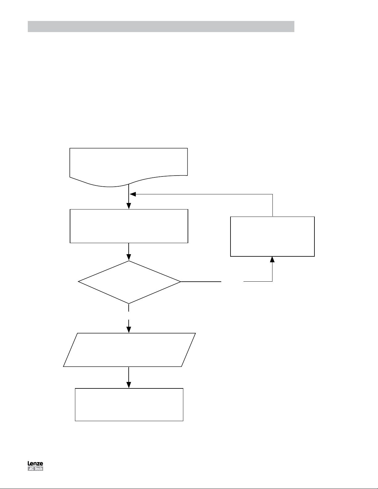
memory and the internal flash memory. Figure 1 illustrates the flow of the program preparation process.
Prepare User Program
COMPILER
Any Error?
NO
Load compiled program
to PositionServo drive
Start Execution in
debugger environment
or at next power up
Fix program errors
YES
Figure 1: Program Preparation
PM94P01C 5
Page 8
Introduction
1.3 MotionView / MotionView Studio
There are two versions of MotionView Software: one which resides inside the drive’s memory, referred to as “MotionView
on Board” (MVOB); and one supplied as a PC-installed software package, referred to simply as MotionView. This
manual describes the PC-installed MotionView software for PositionServo drives with P/N ending in EX or RX. The
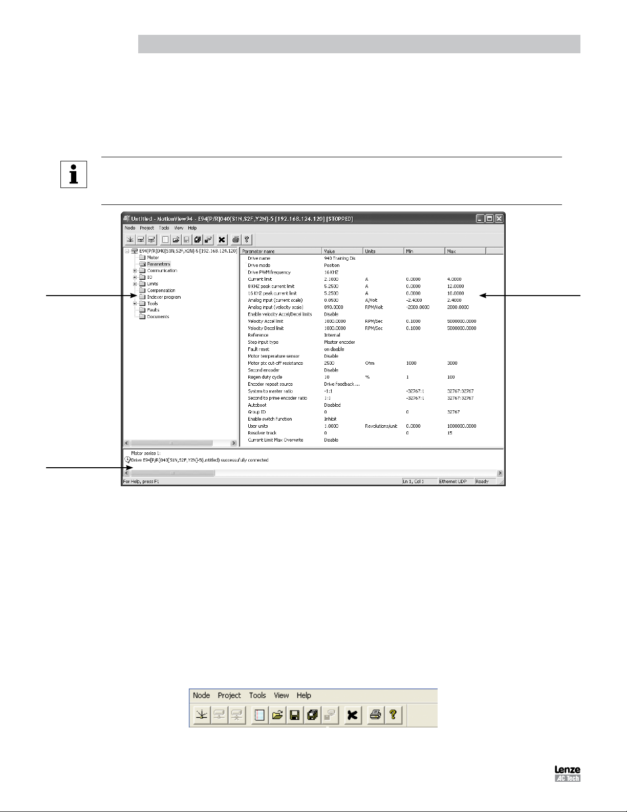
MotionView display is illustrated in Figure 2.
NOTE
For MotionView OnBoard (MVOB), refer to “PositionServo with MVOB Programming Manual”
document number PM94M01
Parameter Tree
Window
Message
Window
Figure 2: MotionView Parameters Display
MotionView is the universal programming software used to communicate with and configure the PositionServo drive. The
MotionView platform is segmented into three windows. The first window is the “Parameter Tree Window”. This window
is used much like Windows Explorer. The various parameter groups for the drive are represented here as folders or files.
Once the desired parameter group file is selected, all of the corresponding parameters within that parameter group will
appear in the second window, the “Parameter View Window”. The user can then enable, disable or edit drive features
or parameters in the Parameter View window. The third window is the “Message Window”. This window is located at the
bottom of the screen and will display communication status and errors.
Parameter View
Window
1.3.1 Main Toolbar
The functions of MotionView are accessible via the Main Toolbar as illustrated in Figure 3. If a function in a pull-down
menu or an icon is greyed out that denotes the function is unavailable. A function may be unavailable because a drive
is not physically connected to the network or the present set-up and operation of the drive prohibits access to that
function.
Figure 3: Main Menu and Toolbar
PM94P01C6
Page 9
Introduction
Table 3a: Main Menu Text Pull-Down Folders
Main Menu
Node Project Tools View Help
New configuration file New project Browse motor database Toolbar MotionView help
Open configuration file Open project Clear output window Status Bar Product manuals
Save configuration file Close project About MotionView
Load configuration file Save project Time stamp
Set all parameters to default Save all configuration files
Connect drive Options
Disconnect all coneected drives Connection setup
Remove node from project Recent file
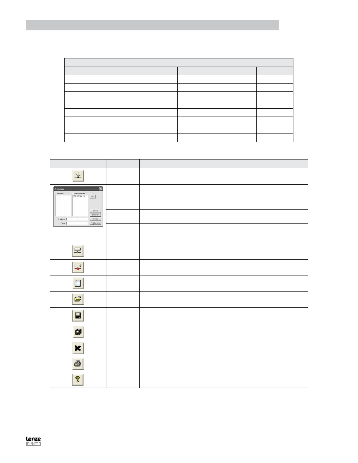
Table 3b: Main Menu Icon Functions
Icon Function Description
Connect Build a connection list of the drive(s) to communicate with on the network. Build the
connection list by using any one of these three methods:
Discover [Discover] button discovers all drives on the network that are available for connectivity. Once
Connect If the IP address on the drive is known, enter it in the IP address dialog box and then select
Find by name If a drive has been assigned a specified “Drive Name”, enter this name in the Name dialog box
Connected Drive is connected as a node on the network.
Disconnect Terminate connection to the drive selected (backlit) in the Node Tree.
Add File Import a configuration file to the drive
Open File Recall & open any previously saved configuration files and connection parameters.
Save Save the configuration file and the connection parameters of the drive selected in Node Tree.
Save As Save the configuration file and the connection parameters of the drive selected in Node Tree.
Remove Node Remove a node from the network
drives have been discovered they are listed in the ‘Connect to drive’ list box. To connect one
or a number of drives highlight their IP address in this window and press the [Connect] button.
The ‘Ctrl’ key on your keyboard can be used to select multiple drives for connection.
[Connect] to access the drive.
and then select [Find by name]. The IP address should then appear in the “Connect To Drive”
list. The drive can now be connected by highlighting and pressing the [Connect] button.
Print Print a report for the currently selected drive, containing all parameter set-up and
Help Open MotionView Help folder (from original installation CD)
programming information.
PM94P01C 7
Page 10
Introduction
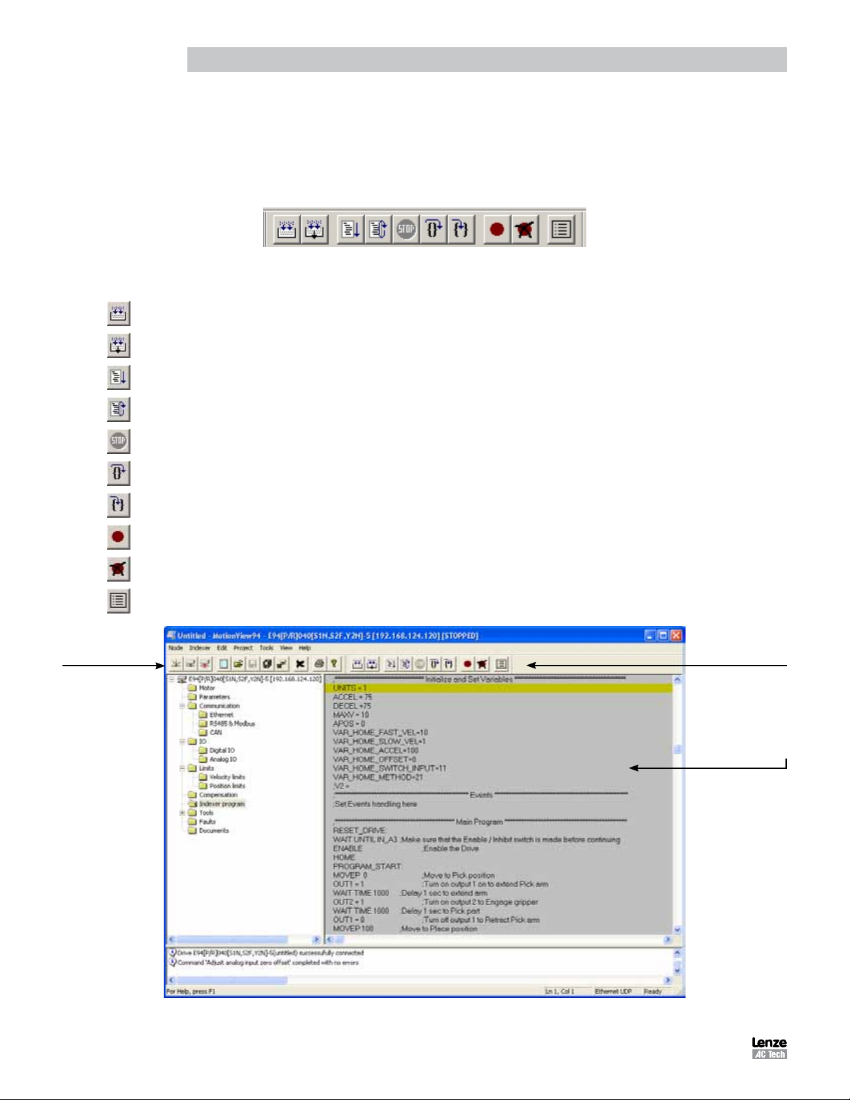
1.3.2 Program Toolbar
To view the Program Toolbar, click on the [Indexer Program] folder in the Node Tree. Click anywhere inside the gray
Indexer program in the right-hand parameter window to bring up the program toolbar. This paragraph contains a brief
description of the programming tools: Compile, Load with Source, Run, Reset, Stop, Step Over, Step Into, Set Breakpoint
and Remove Breakpoint. For detailed descriptions of the program toolbar functions refer to paragraphs 1.3.3 and 1.4.
Figure 4: Program Toolbar
Icon Function Description
Compile Check compilation of the indexer program currently in the List View window.
Compile & Load w/ Source Load program including source code to the PositionServo drive listed in Node Tree.
Run Start / Continue program execution.
Main
Toolbar
Reset
Stop
Step Over Execute each line of code in the program sequentially on each press on the [Step Over] button excluding subroutines.
Step Into Execute each line of code in the program sequentially on each press on the [Step Into] button, including subroutines.
Set Breakpoint Set breakpoint at current location of cursor in Indexer program.
Remove Breakpoint Remove breakpoint from current location of cursor in Indexer program.
Watch Window Display Parameter I/O window
Reset Drive. Disable drive, stop program execution, and return program processing to the beginning. Program will not
restart program execution automatically.
Stop program execution on completion of the current statement being executed. WARNING: Stop button does not
place the drive in a disable state or prevent execution of motion commands waiting on the motion stack.
Program
Toolbar
Program
User
Area
Figure 5: MotionView - Indexer Program Display
PM94P01C8
Page 11

Introduction
1.3.3 MotionView Studio - Indexer Program
The MotionView Studio provides a tool suite used by MotionView to enter, compile, load and debug the user program.
To view and develop the user program, select the [Indexer Program] folder in the Parameter (Node) Tree window. Once
selected the program toolbar is displayed. The program displayed in the View window is uploaded from the drive when
the connection is made between MotionView and the drive. This upload is always performed regardless of program
running state. Click anywhere in the Parameter View Window to edit the Indexer program.
Common Programming Actions
Load User program from the PC to MotionView
- Select [Indexer Program] in the Node Tree.
- Select [Import] on the program toolbar.
Select the program to import from the PC folder where it is located. This procedure loads the program from the
file to the editor window. It doesn’t load the program to the drive’s memory.
Compile program and Load to the drive
- Select [Indexer Program] in the Node Tree.
- Select [Compile & Load W Source] on the program toolbar to to compile the program and load the source
code and the compiled binary file to the PositionServo drive. The original source code contained in the drive can
be viewed whenever the drive is accessed through MotionView and the Indexer Program folder is opened.
- Select [Compile] to check syntax errors without loading the program to drive. If the compiler finds any syntax
error, compilation stops. Errors are reported in bottom portion of the screen in Message window.
Save User program from MotionView to PC.
- Select [Indexer Program] in the Node Tree.
- Select [Export] ] on the program toolbar.
The program will be saved to the Windows “My Documents” folder by default.
Run User program in drive.
- Select [Indexer Program] in the Node Tree.
- Select [Run] on the program toolbar.
If the program is already running, then first select [Reset] or [Stop] to stop the program.
Step Through the User program.
- Select [Indexer Program] in the Node Tree.
- Select [Step] or [Step over] on the program toolbar.
If [Step] is selected, the drive will execute the program one step at a time including subroutines. If [Step Over] is
selected, the drive will execute the program one step at a time excluding subroutines. The program statement
under execution will be highlighted. If the program is running, it will have to be either stopped or reset.
Set Breakpoint(s) in the program
- Select [Indexer Program] in the Node Tree.
- Place the cursor at the point in the program where the program will stop.
- Select [Set Breakpoint] or [Remove Breakpoint] on the program toolbar.
A convenient way to debug a user program is to insert breakpoints at critical junctions throughout the program.
These breakpoints stop the drive from executing the program, but do not disable the drive and the position
variables. Once the program has stopped, the user can continue to run the program, step through the program
or reset the program.
PM94P01C 9
Page 12

Introduction
Stop program execution
- Select [Indexer Program] in the Node Tree.
- Select [Stop] on the program toolbar.
The program will stop after completing the current statement. Select [Run] to resume the program from the
same point.
IMPORTANT!
The [Stop] button only stops the execution of the program code.
It does not stop motion or disable the drive.
Restart Program execution
- Select [Indexer Program] in the Node Tree.
- Select [Reset] on the program toolbar.
The program will be reset and the drive will be disabled. Variables within the drive are not cleared (reset) when
program execution is reset. It is important that any variables used by the programmer are set to safe values at
the start of the user program.
1.4 Programming Basics
The user program consists of statements which when executed will not only initiate motion moves but also process
the drives I/O and make decisions based on drive parameters. Before motion can be initiated, certain drive and I/O
parameters must be configured. To configure these parameters perform the following procedure.
Parameter setup
Select [Parameter] folder in the Node Tree window and set the following parameters.
Set the “Drive” to “Position”:
- Select [Drive mode] from the Parameter View Window.
- Select [Position], [Velocity], or [Torque] from the drop down menu depending on the mode the drive is to be
operated in. In order to execute the examples contained in this section of the manual the drive will need to be
in [Position] mode.
Set the [Reference] to [Internal]:
- Select [Reference] from the Parameter View Window.
- Select [Internal] from the pull down menu to select the user program as the source of the Torque, Velocity, or
Position Reference.
Set the [Enable switch function] to [Inhibit]:
- Select [Enable switch function] from the Parameter View Window.
- Select [Inhibit] from the menu to allow the user program control of the enable / disable status of the drive.
Input A3 will now act as a hardware inhibit.
I/O Configuration
Input A3 is the Inhibit/Enable special purpose input. Refer to the PS User Manual (S94P01) for more information. Before
executing any motion related statements, the drive must be enabled by executing “ENABLE” statement. “ENABLE”
statement can only be accepted if input A3 is made. If at any time while drive is enabled A3 deactivates then the fault
“F36” (“Drive Disabled”) will result. This is a hardware safety feature.
PM94P01C10
Page 13
Introduction
Basic Motion Program
Select [Indexer program] from the Node Tree. The Parameter View window will display the current User Program stored in the
drive. Note that if there is no valid program in the drive’s memory the program area will be empty.
WARNING!
This program will cause motion. The motor should be disconnected from the application (free to rotate)
or if a motor is connected, the shaft must be free to spin 10 revs forward and reverse from the location of
the shaft at power up. Also, the machine must be capable of 10 RPS and an accel / decel of 5 RPSS.
In the program area, clear any existing program and replace it with the following program:
UNITS=1
ACCEL = 5
DECEL = 5
MAXV = 10
ENABLE
MOVED 10
MOVEDISTANCE -10
END
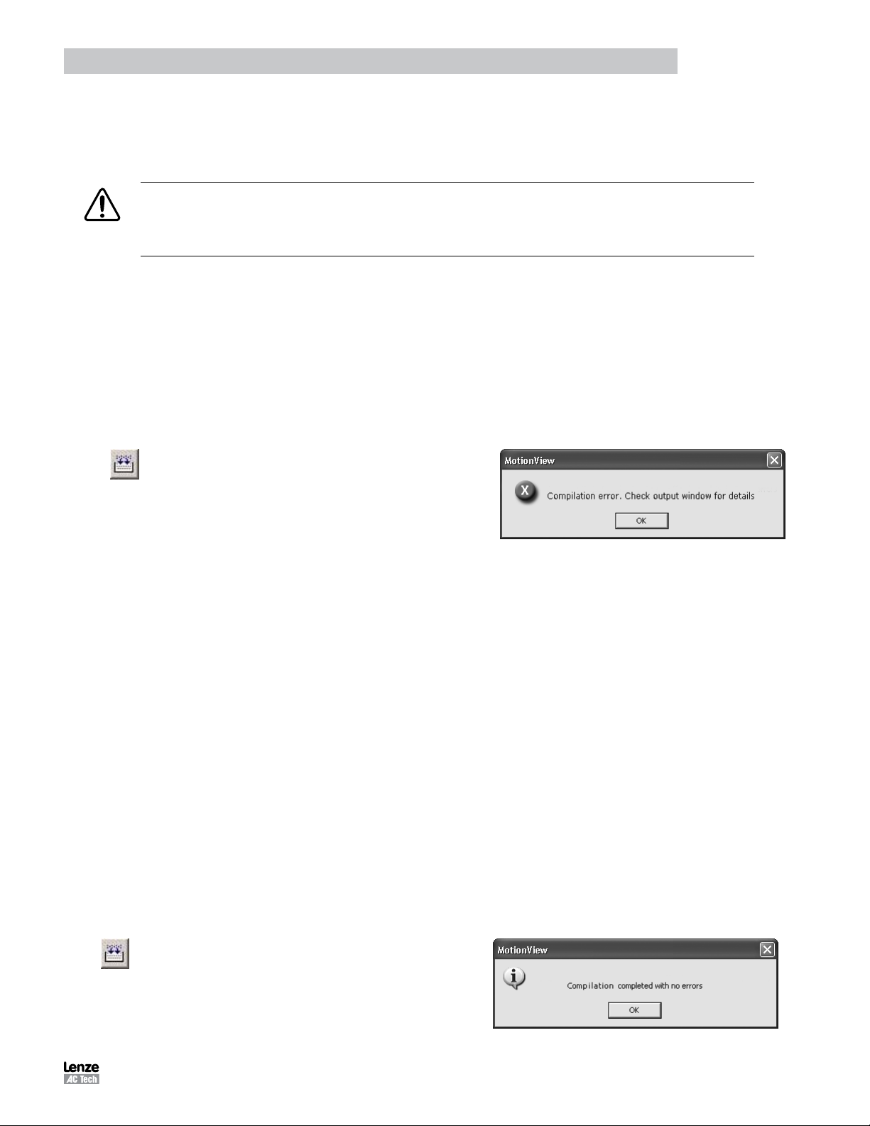
After the text has been entered into the program
area, select the [Compile] icon from the toolbar. After
compilation is done, a “Compilation Error” message
should appear:
Click [OK] to dismiss the “Compliation error” dialog box. The cause of the compilation error will be displayed in the
Message window, located at the bottom of the MotionView OnBoard window. MotionView will also highlight the program
line where the error occurred.
UNITS=1
ACCEL = 5
DECEL = 5
MAXV = 10 ;
ENABLE
MOVED 10 ;
MOVEDISTANCE -10
END
The problem in this example is that “MOVEDISTANCE” is not a valid command. Change the text “MOVEDISTANCE”
to “MOVED”.
UNITS=1
ACCEL = 5
DECEL = 5
ENABLE
MOVED 10
MOVED -10
END
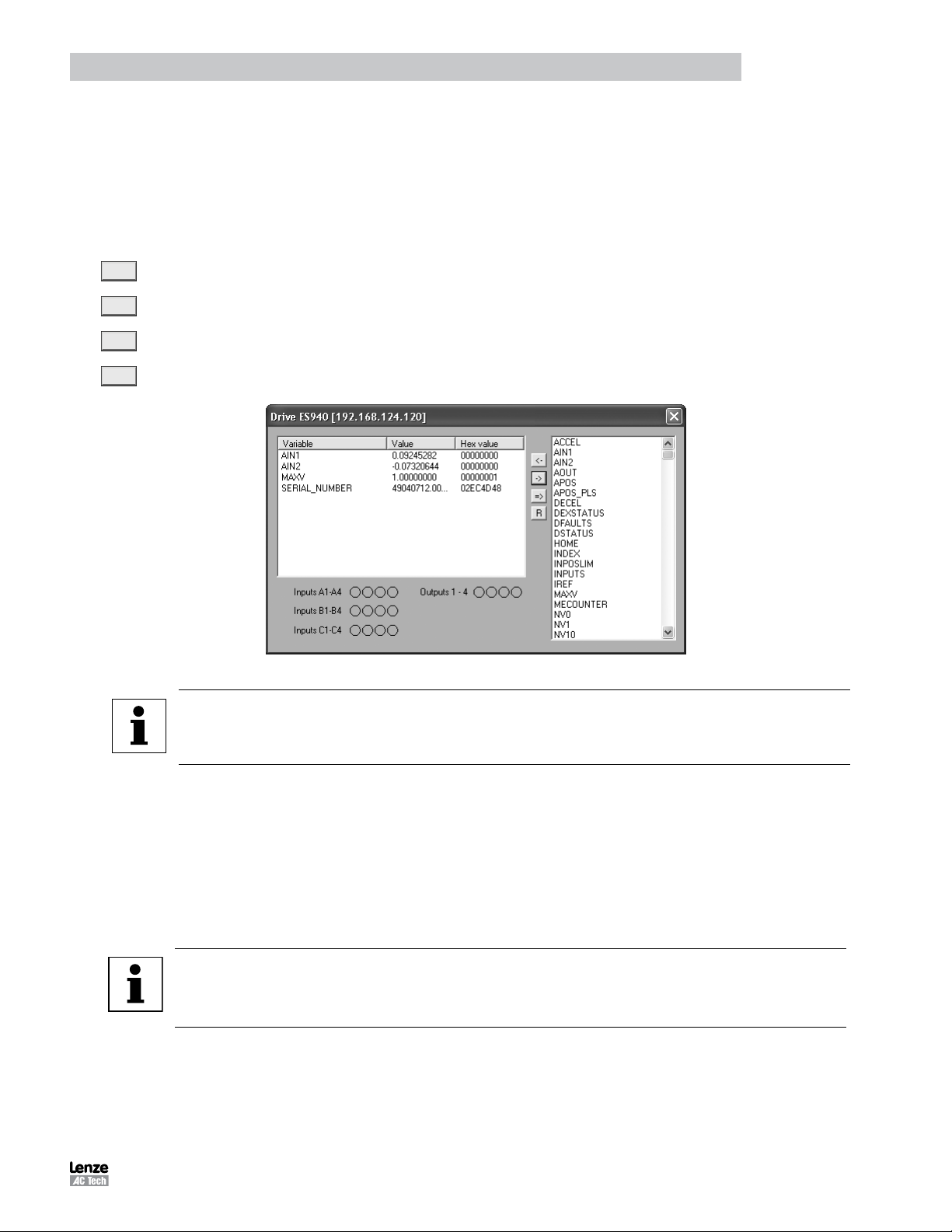
After editing the program, select the [Compile]
icon from the program toolbar. After compilation
is done, the “Compilation Complete” message box
should appear.
PM94P01C 11
Page 14

Introduction
The program has now been compiled without errors. Select [Compile & Load W Source] to load the program to the
drive’s memory. Click [OK] to dismiss the dialog box.
To Run the program, input A3 must be active to remove the hardware inhibit. Select the [Run] icon
on the program toolbar. The drive will start to execute the User Program. The motor will spin 10
revolutions in the CCW direction and then 10 revolutions in the CW direction. After all the code has
been executed, the program will stop and the drive will stay enabled.
To Restart the program, select the [Reset] icon on the program toolbar. This will disable the drive
and reset the program to execute from the start. The program does not run itself automatically. To
run the program again, select the [Run] icon on the toolbar.
Program Layout
When developing a program, structure is very important. It is recommended that the program be divided up into the
following 7 segments:
Header: The header defines the title of the program, who wrote the program and description of what
the program does. It may also include a date and revision number.
I/O List: The I/O list describes what the inputs and outputs of the drive are used for. For example input A1
might be used as a Start Switch.
Init & Set Var: Initialize and Set Variables defines the drives settings and system variables. For example
here is where acceleration, deceleration and max speed might be set.
Events: An Event is a small program that runs independently of the main program. This section is
used to define the Events.
Main Program: The Main Program is the area where the process of the drive is defined.
Sub-Routines: This is the area where any and all sub-routines should reside. These routines will be called
out from the Main Program with a GOSUB command.
Fault Handler: This is the area where the Fault Handler code resides. If the Fault handler is utilized this code
will be executed when the drive generates a fault.
The following is an example of a Pick and Place program divided up into the above segments.
***************************** HEADER **************************************
;Title: Pick and Place example program
;Author: Lenze - AC Technology
;Description: This is a sample program showing a simple sequence that
; picks up a part, moves to a set position and places the part
;**************************** I/O List ************************************
; Input A1 - not used
; Input A2 - not used
; Input A3 - Enable Input
; Input A4 - not used
; Input B1 - not used
; Input B2 - not used
; Input B3 - not used
; Input B4 - not used
; Input C1 - not used
; Input C2 - not used
; Input C3 - not used
; Input C4 - not used
; Output 1 - Pick Arm
; Output 2 - Gripper
; Output 3 - not used
; Output 4 - not used
PM94P01C12
Page 15

Introduction
;********************** Initialize and Set Variables ***********************
UNITS = 1
ACCEL = 75
DECEL =75
MAXV = 10
;V1 =
;V2 =
;********************** Events *********************************************
;Set Events handling here
;No events are currently defined in this program
;********************** Main Program **************************************
RESET_DRIVE: ;Place holder for Fault Handler Routine
WAIT UNTIL IN_A3: ;Make sure that the Enable input is made before continuing
ENABLE ;Enable output from drive to motor
PROGRAM_START: ;Place holder for main program loop
MOVEP 0 ;Move to Pick position
OUT1 = 1 ;Turn on output 1 to extend Pick arm
WAIT TIME 1000 ;Delay 1 sec to extend arm
OUT2 = 1 ;Turn on output 2 to Engage gripper
WAIT TIME 1000 ;Delay 1 sec to Pick part
OUT1 = 0 ;Turn off output 1 to Retract Pick arm
MOVED -10 ;Move 10 REVs to Place position
OUT1 = 1 ;Turn on output 1 to extend Pick arm
WAIT TIME 1000 ;Delay 1 sec to extend arm
OUT2 = 0 ;Turn off output 2 to Disengage gripper
WAIT TIME 1000 ;Delay 1 sec to Place part
OUT1 = 0 ;Retract Pick arm
GOTO PROGRAM_START ;Loop back and continuous execute main program loop
END
;********************** Sub-Routines ***************************************
;Enter Sub-Routine code here
;********************** Fault Handler Routine ********************
;Enter Fault Handler code here
ON FAULT
;No Fault Handler is currently defined in this program
ENDFAULT
Saving Configuration File to PC
The “Configuration File” consists of all the parameter settings for the drive, as well as the User Program. Once you are
done setting up the drive’s parameters and have written your User Program, you can save these setting to your computer.
To save the settings, select [Save All] from the Main toolbar. Then simply assign your program a name, (e.g. Basic
Motion), and click [Save] in the dialog box. The configuration file has a “.dcf” extension and by default will be saved to the
“My Documents” folder.
Loading Configuration File to the Drive
There are times when it is desired to import (or export) the program to another drive. Other times the program was
prepared off-line. In both scenarios, the program or configuration file needs to be loaded from the PC to the drive. To
load the configuration file to the drive, select [Load Configuration] from the Main toolbar. Then simply select the
program you want to load and click [Open] in the dialog box. MotionView will first compile the selected program. Once
compiled, the [Compilation Complete] dialog box should appear. Click [OK] to dismiss this dialog box. MotionView will
then load the selected file to the drive. When done, a “Parameters Successfully Loaded” or similar message will be
displayed in the Message Window.
PM94P01C 13
Page 16

Introduction
Motion source (Reference)
The PositionServo can be set up to operate in one of three modes: Torque, Velocity, or Position. The drive must
be given a command before it can initiate any motion. The source for commanding this motion is referred to as the
“Reference”. With the PositionServo you have two ways of commanding motion, or two types of References. When
the drive’s command signal is from an external source, for example a PLC or Motion Controller, it is referred to as an
External Reference. When the drive is being given its command from the User program or through one of the system
variables it is referred to as an Internal Reference.
Table 4: Setting the Reference
“Reference” Parameter Setting
Mode External Internal
Torque
Velocity
Position
User Program (Trajectory generator output)
Units
All motion statements in the drive work with User units. The statement on the first line of the test program, UNITS=1,
sets the relationship between User units and motor revolutions. For example, if UNITS=0.5 the motor will turn 1/2 of
a revolution when commanded to move 1 Unit. When the UNITS variable is set to zero, the motor will operate with
encoder counts as User units.
Analog input AIN1 System variable “IREF”
Analog input AIN1 System variable “IREF”
Step/Direction Inputs
Master Encoder Pulse Train Inputs
User Program/Interface
(Trajectory generator)
Time base
Time base is always in seconds i.e. all time-related values are set in USER UNITS/SEC.
Enable/Disable/Inhibit drive
Set “Enable switch function” to “Run”.
When the “Enable switch function” parameter is set to Run, and the Input A3 is made, the drive will be enabled. Likewise,
toggling input A3 to the off state will disable the drive.
- Select “Parameter” from the Parameter Tree Window.
- Select “Enable switch function” from the Parameter View Window.
- Select “Run” from the popup menu. This setting is primarily used when operating without any user’s program
in torque or velocity mode or as position follower with Step&Direction/Master Encoder reference.
Set “Enable switch function” to “Inhibit”.
In the example of the Enable switch function being set to Run the decision on when to enable and disable the drive is
determined by an external device, PLC or motion controller. The PositionServo’s User Program allows the programmer
to take that decision and incorporate it into the drive’s program. The drive will execute the User Program whether the
drive is enabled or disabled, however if a motion statement is executed while the drive is disabled, the F36 fault will
occur. When the “Enable switch function” parameter is set to Inhibit, and Input A3 is on, the drive will be disabled and
remain disabled until the ENABLE statement is executed by the User Program.
- Select “Parameter” from the Parameter Tree Window.
- Select “Enable switch function” from the Parameter View Window.
- Select “Inhibit” from the popup menu.
PM94P01C14
Page 17

Introduction
Faults
When a fault condition has been detected by the drive, the following actions will occur:
- Drive will Immediately be placed in a Disabled Condition.
- Motion Stack will be flushed of any Motion Commands
- Execution of the user program will be terminated and program control will be handed over to the Fault Handler
section. If no Fault handler is described then program execution will terminate. See fault handler section.
- A fault code defining the nature of the drive trip will be written to the DFAULTS system variable and can be
accessed by the fault handler. Refer to section 2.13 for a list of fault codes.
- The fault code will will be displayed on the drive display.
- Dedicated “Ready” output will turn off.
- Any Output with assigned special function “Fault” will turn on.
- Any Output with assigned special function “ready/enabled” will turn off.
- The “enable” status indicator on the drive display will turn off indicating drive in disabled state.
Clearing a fault condition can be done in one of the following ways:
- Select the [Reset] button from the toolbar.
- Execute the RESUME statement at the end of the Fault Handler routine (see Fault Handler
example).
- Send “Reset” command over the Host Interface.
- Cycle power (hard reset).
Fault Handler
The Fault Handler is a code segment that will be executed when the drive is experiencing a fault. The fault handler allows
the programmer to analyze the type of fault and define a recovery process for the drive and permits the continuation of
program execution. While the drive is executing the Fault Handler Routine the drive is disabled and therefore will not
be able to detect any additional faults that might occur. Fault handler code should be treated as the drive’s first reaction
on fault. While it executes, the drive will not respond to any I/O, interface commands etc. Therefore the user should
use the fault handler to manipulate time critical and safety related I/O and variables and then exit the Fault Handler
Routine by executing a “RESUME” statement for a full stop after statement. The Resume statement permits program
execution to leave the fault handler and resume back in the main program section of the user code. Use the Resume
statement to jump back to a section of the main program that designates the recovery process for the fault. Waiting
in Fault handler for I/O state change or for interface command is not allowed. Do that in the code where you point the
“RESUME” statement.
Without Fault Handler
To simulate a fault, restart the Pick and Place example program. While the program is running, switch the ENABLE
input IN_A3 to the off state. This will cause the drive to generate an F_36 fault (Drive Disabled) and put the drive
into Fault Mode. While the drive is in Fault Mode, any digital output currently active will remain active and any output
deactivated will remain deactivated, excluding the dedicated ready output and any output that has been assigned
special functionality. The program execution will stop and any motion moves will be terminated. In this example the Pick
and Place arm may not be in a desired location when the program goes into the fault mode.
PM94P01C 15
Page 18

Introduction
With Fault Handler
Add the following code to the end of your sample program. While the program is running, switch the ENABLE input
IN_A3, to the off state. This will cause the drive to generate an F_36 fault (Drive Disabled) and put the drive into a Fault
Mode. From this point the Fault Handler Routine will take over.
F_PROCESS:
WAIT UNTIL IN_A4==1 ;Wait until reset switch is made
WAIT UNTIL IN_A4==0 ;and then released before
GOTO RESET_DRIVE ;returning to the beginning of the program
END
;*********************** Sub-Routines **************************************
Enter Sub-Routines here;
;*********************** Fault Handler Routine *****************************
ON FAULT ;Statement starts fault handler routine
;Motion stopped, drive disabled, and events no longer
;scanned while executing the fault handler routine.
OUT2 = 0 ;Output 1 off to Disengage gripper.
;This will drop the part in the gripper
OUT1 = 0 ;Retract Pick arm to make sure it is up and out of the way
RESUME F_PROCESS ;program restarts from label F_PROCESS
ENDFAULT ;fault handler MUST end with this statement
NOTE
The following statements can not be used inside the Fault Handler Routine:
- ENABLE
- WAIT
- MOVE
- MOVED
- MOVEP
- MOVEDR
- MOVEPR
- MDV
- MOTION SUSPEND
- MOTION RESUME
- GOTO, GOSUB
- JUMP
- ENABLE
- VELOCITY ON/OFF
Refer to section 2.1 for additional details and the Language Reference section for the statement
“ON FAULT/ENDFAULT”.
PM94P01C16
Page 19
Introduction
1.5 Using Advanced Debugging Features
To debug a program or view the I/O, open the Diagnostic window by clicking on the [Tools] in the Parmeter (Node)
Tree list then click on the [Parameter & I/O View] button. The Diagnostic window will open. This window allows the
programmer to monitor and set variables, and to view status of drive digital inputs and outputs.
Click on a variable in the variable list on the right-hand side to select that parameter
< -
- >
= >
R
Use the left arrow button to add variables after selecting a variable.
Use the right arrow button to remove variables after selecting a variable.
Use the double right arrow button to remove all variables in left-hand Diagnostic window.
Use the [R] (Refresh) button to refresh variable values.
Figure 6: Variable Diagnostic Display
NOTE
Write-only variables cannot be read. Attempts to either display a write-only variable in the diagnostic
window or to read a write-only variable via network communications can show erroneous data.
1.6 Inputs and Outputs
Analog Input and Output
- The PositionServo has two analog inputs. These analog inputs are utilized by the drive as System Variables and
are labeled “AIN1” and “AIN2”. Their values can be directly read by the User Program or via a Host Interface.
Their value can range from -10 to +10 and correlates to ±10 volts analog input.
- The PositionServo has one analog output. This analog output is utilized by the drive as a System Variable and
is labeled “AOUT”. It can be directly written by the User Program or via a Host Interface. Its value can range
from -10 to +10 which correlates to ± 10 volts analog input.
NOTE
If an analog output is assigned to any special function from MotionView, writing to AOUT from the
User Program will not change its value. If an analog output is set to “Not assigned” then it can be
controlled by writing to the AOUT variable.
PM94P01C 17
Page 20

Introduction
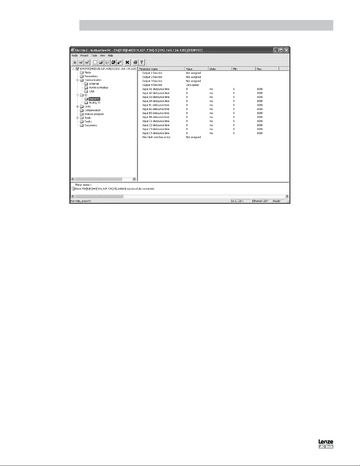
Digital Inputs
- The PositionServo has twelve digital inputs that are utilized by the drive for decision making in the User Program.
Example uses: travel limit switches, proximity sensors, push buttons and hand shaking with other devices.
- Each input can be assigned an individual debounce time via MotionView. From the Parameter Tree, select [IO].
Then select the [Digital Input] folder. The debounce times will be displayed in the Parameter View Window.
Debounce times can be set between 0 and 1000 ms (1ms = 0.001 sec). Debounce times can also be set via
variables in the user program.
- The twelve inputs are separated into three groups: A, B and C. Each group has four inputs and share one
common: Acom, Bcom and Ccom respectfully. The inputs are labeled individually as IN_A1 - IN_A4, IN_B1
- IN_B4 and IN_C1 - IN_C4.
- In addition to monitoring each input individually, the status of all twelve inputs can be represented as one binary
number. Each input corresponds to 1 bit in the INPUTS system variable. Use the following format:
System
Variable
INPUTS
Bit # 11 10 9 8 7 6 5 4 3 2 1 0
Input
Name
C4 C3 C2 C1 B4 B3 B2 B1 A4 A3 A2 A1
- Some inputs can have additional special functionality such as Travel Limit switch, Enable input, and Registration
input. Configuration of these inputs is done from MotionView or through variables in the user program. Input
special functionality is summarized in the table below and in the following sections. The current status of the
drive’s inputs is available to the programmer through dedicated System Flags or as bits of the System Variable
INPUTS. Table 5 summarizes the special functions for the inputs.
Table 5: Input Functions
Input Special Function
Input A1 negative limit switch
Input A2 positive limit switch
Input A3 Inhibit/Enable input
Input A4 N/A
Input B1 N/A
Input B2 N/A
Input B3 N/A
Input B4 N/A
Input C1 N/A
Input C2 N/A
Input C3 Registration sensor input
Input C4 N/A
PM94P01C18
Page 21

Introduction
Read Digital Inputs
The Pick and Place example program has been modified below to utilize the “WAIT UNTIL” inputs statements in place
of the “WAIT TIME” statements. IN_A1 and IN_A4 will be used as proximity sensors to detect when the pick and place
arm is extended and when it is retracted. When the arm is extended, IN_A1 will be in an ON state and will equal “1”.
When the arm is retracted, IN_A4 will be in an ON state and will equal “1”.
;********************* Main Program ****************************************
RESET_DRIVE: ;Place holder for Fault Handler Routine
WAIT UNTIL IN_A3 ;Make sure that the Enable input is made before continuing
ENABLE
PROGRAM_START:
WAIT UNTIL IN_A4==1 ;Make sure Arm is retracted
MOVEP 0 ;Move to Pick position
OUT1 = 1 ;Turn on output 1 to extend Pick arm
WAIT UNTIL IN_A1==1 ; Arm extend
OUT2 = 1 ;Turn on output 2 to Engage gripper
WAIT TIME 1000 ;Delay 1 sec to Pick part
OUT1 = 0 ;Turn off output 1 to Retract Pick arm
WAIT UNTIL IN_A4==1 ;Make sure Arm is retracted
MOVED -10 ;Move 10 REVs to Place position
OUT1 = 1 ;Turn on output 1 on to extend Pick arm
WAIT UNTIL IN_A1==1 ; Arm is extended
OUT2 = 0 ;Turn off output 2 to Disengage gripper
WAIT TIME 1000 ;Delay 1 sec to Place part
OUT1 = 0 ;Retract Pick arm
WAIT UNTIL IN_A4==1 ;Arm is retracted
GOTO PROGRAM_START
END
Once the above modifications have been made, export the program to file and save it as “Pick and Place with I/O”, then
compile, download and test the program.
ASSIGN & INDEX - Using inputs to generate predefined indexes
“INDEX” is a variable on the drive that can be configured to represent a certain group of inputs as a binary number.
“ASSIGN” is the command that designates which inputs are utilized and how they are configured.
Below the Pick and Place program has been modified to utilize this “INDEX” function. The previous example program
simply picked up a part and moved it to a place location. For demonstration purposes we will add seven different place
locations. These locations will be referred to as Bins. What Bin the part is placed in will be determined by the state of
three inputs, B1, B2 and B3.
Bin 1 - Input B1 is made
Bin 2 - Input B2 is made
Bin 3 - Inputs B1 and B2 are made
Bin 4 - Input B3 is made
Bin 5 - Inputs B1 and B3 are made
Bin 6 - Inputs B2 and B3 are made
Bin 7 - Inputs B1, B2 and B3 are made
The “ASSIGN” command is used to assign the individual input to a bit in the “INDEX” variable. ASSIGN INPUT <input
name> AS BIT <bit #>
;*********************** Initialize and Set Variables *******************
ASSIGN INPUT IN_B1 AS BIT 0 ;Assign the Variable INDEX to equal 1 when IN_B1 is made
ASSIGN INPUT IN_B2 AS BIT 1 ;Assign the Variable INDEX to equal 2 when IN_B2 is made
ASSIGN INPUT IN_B3 AS BIT 2 ;Assign the Variable INDEX to equal 4 when IN_B4 is made
PM94P01C 19
Page 22

Introduction
Table 6: Bin Location, Inputs & Index Values
Bin Location Input State INDEX Value
Bin 1 Input B1 is made 1
Bin 2 Input B2 is made 2
Bin 3 Inputs B1 and B2 are made 3
Bin 4 Input B3 is made 4
Bin 5 Inputs B1 and B3 are made 5
Bin 6 Inputs B2 and B3 are made 6
Bin 7 Inputs B1, B2 and B3 are made 7
The Main program has been modified to change the end place position based on the value of the “INDEX” variable.
;************************** Main Program **********************************
ENABLE
PROGRAM_START:
WAIT UNTIL IN_A4==1 ;Make sure Arm is retracted
MOVEP 0 ;Move to (ABS) to Pick position
OUT1 = 1 ;Turn on output 1 to extend Pick arm
WAIT UNTIL IN_A1==1 ;Arm extends
OUT2 = 1 ;Turn on output 2 to Engage gripper
WAIT TIME 1000 ;Delay 1 sec to Pick part
OUT1 = 0 ;Turn off output 1 to Retract Pick arm
WAIT UNTIL IN_A4==0 ;Make sure Arm is retracted
IF INDEX==1 ;In this area we use the If statement to
GOTO BIN_1 ;check and see what state inputs B1, B2 & B3
ENDIF ;are in.
IF INDEX==2 ; INDEX = 1 when input B1 is made
GOTO BIN_2 ; INDEX = 2 when input B2 is made
ENDIF ; INDEX = 3 when input B1 & B2 are made.
. ; INDEX = 4 when input B3 is made
. ; INDEX = 5 when input B1 & B3 are made.
. ; INDEX = 6 when input B2 & B3 are made.
IF INDEX==7 ; INDEX = 7 when input B1, B2 & B3 are made
GOTO BIN_7 ;We can now direct the program to one of seven
ENDIF ;locations based on three inputs.
BIN_1: ;Set up for Bin 1
MOVEP 10 ;Move to Bin 1 location
GOTO PLACE_PART ;Jump to place part routine
BIN_2: ;Set up for Bin 2
MOVEP 20 ;Move to Bin 2 location
GOTO PLACE_PART ;Jump to place part routine
BIN_7: ;Set up for Bin 7
MOVEP 70 ;Move to Bin 7 location
GOTO PLACE_PART ;Jump to place part routine
PLACE_PART:
OUT1 = 1 ;Turn on output 1 to extend Pick arm
WAIT UNTIL IN_A4 == 1 ;Arm extends
OUT2 = 0 ;Turn off output 2 to Disengage gripper
WAIT TIME 1000 ;Delay 1 sec to Place part
OUT1 = 0 ;Retract Pick arm
WAIT UNTIL IN_A4 == 0 ;Arm is retracted
GOTO PROGRAM_START
END
PM94P01C20
Page 23

Introduction
NOTE
Any one of the 12 inputs can be assigned as a bit position within the INDEX variable. Only bits 0
through 7 can be used with the INDEX variable. Bits 8-31 are not used and are always set to 0.
Unassigned bits in the INDEX variable are set to 0.
BITS 8-31 (not used) A1 0 A2 A4 0 0 0 0
Limit Switch Input Functions
Inputs A1 and A2 can be configured as special purpose inputs from the [Digital IO] folder in MotionView. They can be set to
one of three settings:
- The “Not assigned” setting designates the inputs as general purpose inputs which can be utilized by the User
Program.
- The “Fault” setting will configure A1 and A2 as Hard Limit Switches. When either input is made the drive will
be disabled, the motor will come to an uncontrolled stop, and the drive will generate a fault. If the negative limit
switch is activated, the drive will display an F-33 fault. If the positive limit switch is activated the drive will display
an F32 fault.
- The “Stop and fault” setting will configure A1 and A2 as End of Travel limit switches. When either input is
made the drive will initiate a rapid stop before disabling the drive and generating an F34 or F35 fault (refer to
section 2.15 for details). The speed of the deceleration will be set by the value stored in the “QDECEL” System
Variable.
NOTE
The “Stop and Fault” function is available in position mode only, (“Drive mode” is set to “Position”).
In all other cases, the Stop and Fault function will act the same as the Fault function.
To set this parameter, select the [IO] folder from the Parameter Tree. Then select the [Digital IO] folder. From the
Parameter View Window, use the pull-down menu next to [Hard Limit Switches Action] to select the status: Not
Assigned, Fault or Stop and Fault.
Digital Outputs Control
- The PositionServo has 5 digital outputs. The “RDY” or READY output is dedicated and will only come on when
the drive is enabled, i.e. in RUN mode. The other outputs are labeled OUT1 - OUT4.
- Outputs can be configured as Special Purpose Outputs. If an output is configured as a Special Purpose Output
it will activate when the state assigned to it becomes true. For example, if an output is assigned the function
“Zero speed”, the assigned output will come on when the motor is not in motion. To configure an output as a
Special Purpose Output, select the [IO] folder from the Parameter Tree. Then select the [Digital IO] folder. From
the Parameter View Window, select the “Output function” parameter you wish to set (1, 2, 3 or 4).
- Outputs that are configured as “Not assigned” can be activated either via the User Program or from a host
interface. If an output is assigned as a Special Purpose Output, neither the user program nor the host interface
can overwrite its status.
- The Systems Variable “OUTPUTS” is a read/write variable that allows the User Program, or host interface,
to monitor and set the status of all four outputs. Each output allocates 1 bit in the OUTPUTS variable. For
example, if you set this variable equal to 15 in the User Program,i.e. 1111 in binary format, then all 4 outputs
will be turned on.
- The example below summarizes the output functions and corresponding System Flags. To set the output, write
any non-0 value (TRUE) to its flag. To clear the output, write a 0 value (FALSE) to its flag. You can also use
flags in an expression. If an expression is evaluated as TRUE then the output will be turned ON. Otherwise, it
will be turned OFF.
OUT1 = 1 ;turn OUT1 ON
OUT2 = 10 ;any value but 0 turns output ON
OUT3 = 0 ;turn OUT3 OFF
OUT2 = APOS>3 && APOS<10 ;ON when position within window, otherwise OFF
PM94P01C 21
Page 24
Introduction
Figure 7: Digital IO Folder
1.7 Events
A Scanned Event is a small program that runs independently of the main program. An event statement establishes a
condition that is scanned on a regular basis. Once established, the scanned event can be enabled and disabled in the
main program. If condition becomes true and EVENT is enabled, the code placed between EVENT and ENDEVENT
executes. Scanned events are used to trigger the actions independently of the main program.
In the following example the Event “SPRAY_GUNS_ON” will be setup to turn Output 3 on when the drive’s position
becomes greater than 25. Note: the event will be triggered only at the instant when the drive position becomes greater
than 25. It will not continue to execute while the position is greater than 25. (i.e. the event is triggered by the transition
in logic from false to true). Note also that main program doesn’t need to be interrupted to perform this action.
;*********************** EVENT SETUP ***************************************
EVENT SPRAY_GUNS_ON APOS>25 ;Event will trigger as position passes 25 in pos dir.
OUT3=1 ;Turn on the spray guns (out 3 on)
ENDEVENT ;End event
;***************************************************************************
Enter the Event code in the EVENT SETUP section of the program. To Setup an Event, the “EVENT” command must
be entered. This is followed by the Event Name “SPRAY_GUNS_ON” and the triggering mechanism, “APOS>25”.
After that a sequence of programming statements can be entered once the event is triggered. In our case, we will turn
on output 3. To end the Event, the “ENDEVENT” command must be used. Events can be activated (turned on) and
deactivated (turned off) throughout the program. To turn on an Event, the “EVENT” command is entered, followed by the
Event Name “SPRAY_GUNS_ON”. This is completed by the desired state of the Event, “ON” or “OFF”. Refer to Section
2.10 for more on Scanned Events.
;***************************************************************************
EVENT SPRAY_GUNS_ON ON ;Enable ‘spray guns on’ event
;***************************************************************************
Two Scanned Events have been added to the Pick and Place program below to trigger a spray gun on and off. The
Event will be triggered after the part has been picked up and is passing in front of the spray guns (position greater than
25). Once the part is in position, output 3 is turned on to activate the spray guns. When the part has passed by the spray
guns, (position greater than 75), output 3 is turned off, deactivating the spray guns.
PM94P01C22
Page 25

Introduction
;*********************** Events ********************************************
EVENT SPRAY_GUNS_ON APOS>25 ;Event will trigger as position passes 25 in pos dir.
OUT3=1 ;Turn on the spray guns (out 3 on)
ENDEVENT ;End event
EVENT SPRAY_GUNS_OFF APOS>75 ;Event will trigger as position passes 75 in pos dir.
OUT3=0 ;Turn off the spray guns (out 3 off)
ENDEVENT ;End event
;*********************** Main Program **************************************
PROGRAM_START: ;Place holder for main program loop
ENABLE ;Enable output from drive to motor
EVENT SPRAY_GUNS_ON ON ;Enable ‘spray guns on’ event
EVENT SPRAY_GUNS_OFF ON ;Enable ‘spray guns off’ event
WAIT UNTIL IN_A4==1 ;Make sure Arm is retracted
MOVEP 0 ;Move to Pick position
OUT1 = 1 ;Turn on output 1 to extend Pick arm
WAIT UNTIL IN_A1==1 ;Arm extends
OUT2 = 1 ;Turn on output 2 to Engage gripper
WAIT TIME 1000 ;Delay 1 sec to Pick part
OUT1 = 0 ;Turn off output 1 to Retract Pick arm
WAIT UNTIL IN_A4==1 ;Make sure Arm is retracted
MOVEP 100 ;Move to Place position
OUT1 = 1 ;Turn on output 1 to extend Pick arm
WAIT UNTIL IN_A1==1 ;Arm extends
OUT2 = 0 ;Turn off output 2 to Disengage gripper
WAIT TIME 1000 ;Delay 1 sec to Place part
OUT1 = 0 ;Retract Pick arm
WAIT UNTIL IN_A4==1 ;Arm is retracted
GOTO PROGRAM_START ;Loop back and continuously execute main program loop
END
1.8 Variables and Define Statement
In the previous program for the pick and place machine constants were used for position limits to trigger the event and
turn the spray gun ON and OFF. If limits must be calculated based on some parameters unknown before the program
runs (like home origin, material width, etc.), then use the User Variables. The PositionServo provides 32 User Variables
V0-V31 and 32 User Network Variables NV0-NV31. In the program below, the limit APOS (actual position) is compared
to V1 for an ON event and V2 for an OFF event. The necessary limit values could be calculated earlier in the program
or supplied by an HMI or host PC.
The DEFINE statement can be used to assign a name to a constant, variable or drive Input/Output. In the program below,
constants 1 and 0 are defined as Output_On and Output_Off. DEFINE is a pseudo statement, i.e it is not executed by
the program interpreter, but rather substitutes expressions in the subsequent program at the time of compilation.
DEFINE Value2 2
DEFINE Value10 10
V1 = Value2+Value10 ; result is 12
V1 = 2+10 ; does exactly same as above, the result is 12
PM94P01C 23
Page 26

Introduction
;*********************** Initialize and Set Variables **********************
UNITS = 1 ;Define units for program, 1=revolution of motor shaft
ACCEL = 5 ;Set acceleration rate for motion command
DECEL = 5 ;Set deceleration rate for motion command
MAXV = 10 ;Maximum velocity for motion commands
V1 = 25 ;Set Variable V1 equal to 25
V2 = 75 ;Set Variable V2 equal to 75
DEFINE Output_On 1 ;Define Name for output On
DEFINE Output_Off 0 ;Define Name for output Off
;*********************** EVENTS *******************************************
EVENT SPRAY_GUNS_ON APOS > V1 ;Event will trigger as position passes 25 in pos dir.
OUT3= Output_On ;Turn on the spray guns (out 3 on)
ENDEVENT ;End event
EVENT SPRAY_GUNS_OFF APOS > V2 ;Event will trigger as position passes 75 in pos dir.
OUT3= Output_Off ;Turn off the spray guns (out 3 off)
ENDEVENT ;End even
;*********************** Main Program *************************************
PROGRAM_START: ;Place holder for main program loop
ENABLE ;Enable output from drive to motor
EVENT SPRAY_GUNS_ON ON ;Enable the ‘spray guns on’ event
EVENT SPRAY_GUNS_OFF ON ;Enable the ‘spray guns off’ event
WAIT UNTIL IN_A4==1 ;Ensure Arm is retracted before running the program
MOVEP 0 ;Move to position 0 to pick part
OUT1 = Output_On ;Turn on output 1 to extend Pick arm
WAIT UNTIL IN_A1==1 ;Check input to make sure Arm is extended
OUT2 = Output_On ;Turn on output 2 to Engage gripper
WAIT TIME 1000 ;Delay 1 sec to Pick part
OUT1 = Output_Off ;Turn off output 1 to Retract Pick arm
WAIT UNTIL IN_A4==1 ;Check input to make sure Arm is retracted
MOVED 100 ;Move to Place position
OUT1 = Output_On ;Turn on output 1 to extend Pick arm
WAIT UNTIL IN_A1==1 ;Check input to make sure Arm is extended
OUT2 = Output_Off ;Turn off output 2 to Disengage gripper
WAIT TIME 1000 ;Delay 1 sec to Place part
OUT1 = Output_Off ;Retract Pick arm
WAIT UNTIL IN_A4==1 ;Check input to make sure Arm is retracted
GOTO PROGRAM_START ;Loop back and continuously execute main program loop
END
1.9 IF/ELSE Statements
An IF/ELSE statement allows the user to execute one or more statements conditionally. The programmer can use an
IF or IF/ELSE construct:
Single IF example:
This example increments a counter, Variable “V1”, until the Variable, “V1”, is greater than 10.
Again:
V1=V1+1
IF V1>10
V1=0
ENDIF
GOTO Again
END
PM94P01C24
Page 27
Introduction
Position Feedback
IF/ELSE example:
This example checks the value of Variable V1. If V1 is greater than 3, then V2 is set to 1. If V1 is not greater than 3,
then V2 is set to 0.
IF V1>3
V2=1
ELSE
V2=0
ENDIF
Whether you are using an IF or IF/ELSE statement the construct must end with ENDIF keyword.
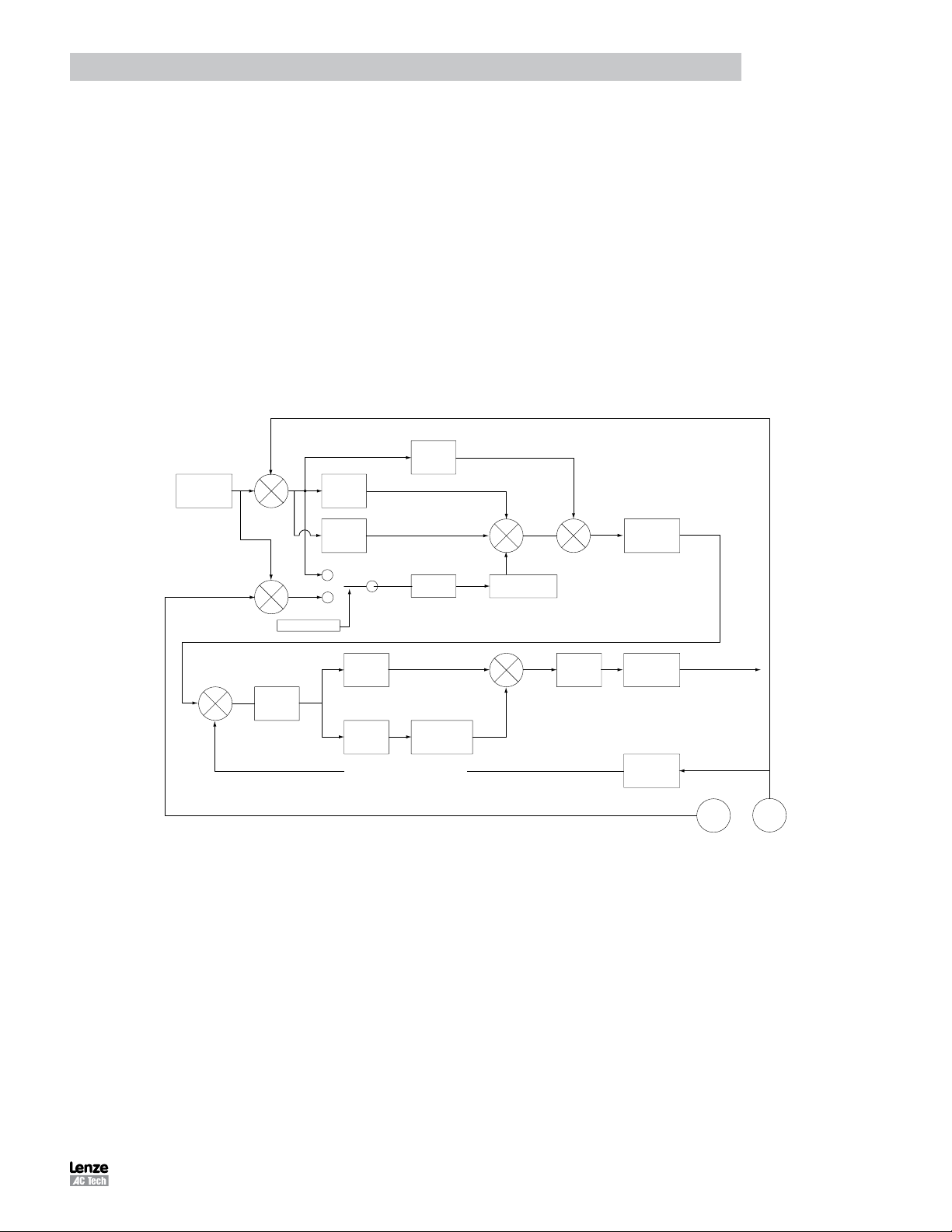
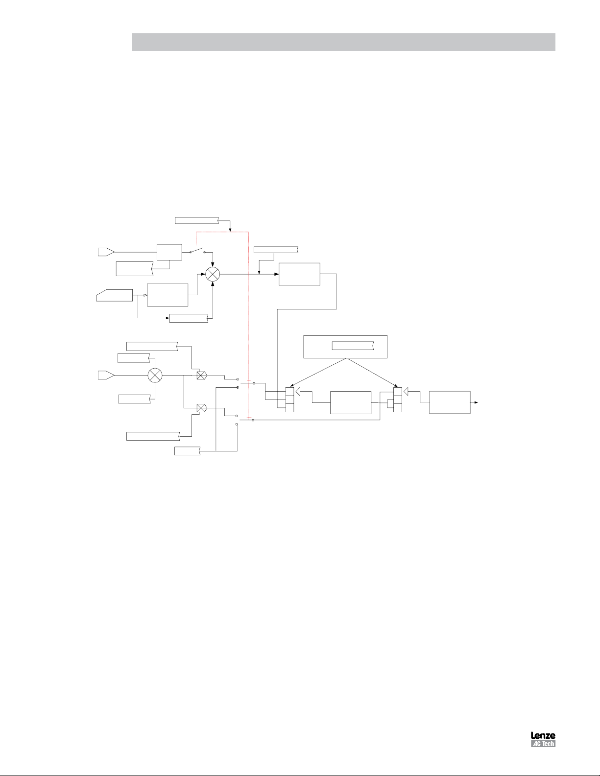
1.10 Motion
Figure 8 illustrates the Position and Velocity regulator of the PositionServo drive.
Kff is automatically calculated
Kff term
I term
+
+
I term Limit and
unti wind-up
+
+
+
Biquad
Convergence
Filter
Position
Command
+
+
-
-
P term
D term
=0
=1
#41 Second Encoder
To Torque Amplifier
Current Command
Secondary
Encoder
Primary
Encoder
Velocity Command
+
-
Velocity
Window
P term
D term
Mechanical Velocity Feedback
I term Limit and
unti wind-up
+
+
Current
Limiter
Biquad
Convergence
Filter
Velocity
Estimator
Figure 8: PositionServo Position and Velocity Regulator’s Diagram
The “Position Command”, as shown in the regulator’s diagram (Figure 9), is produced by a Trajectory Generator.
The Trajectory Generator processes the motion commands produced by the User’s program to calculate the position
increment or decrement, also referred to as the “index” value, for every servo loop. This calculated target (or theoretical)
position is then supplied to the Regulator input.
The main purpose of the Regulator is to set the motors position to match the target position created by the Trajectory
Generator. This is done by comparing the input from the Trajectory Generator with the position feedback from the
encoder or resolver, to control the torque and velocity of the motor. Of course there will always be some error in the
position following. Such error is referred to as “Position Error” and is expressed as follows:
Position Error = Target Position - Actual Position
When the actual Position Error exceeds a certain threshold value a “Position Error limit”, fault (F_PE) will be generated.
The Position Error limit and Position Error time can be set under the Node Tree “Limits”/ “Position Limits” in MotionView.
The Position Error time specifies how long the actual position error can exceed the Position Error limit before the fault
is generated.
PM94P01C 25
Page 28
Introduction
T
1.10.1 Drive Operating Modes
There are three modes of operation for the PositionServo: Torque, Velocity and Position. Torque and Velocity modes
are generally used when the command reference is from an external device, (Ain). Position mode is used when the
command comes from the drives User Program, or from an external device, encoder or a step and direction pulse.
Setting the drive’s mode is done from the [Parameter] folder in MotionView. To command motion from the user program
the drive must be configured to internal reference mode. When the drive is in position mode, it can be placed into a
velocity mode without the need to change operating mode to ‘Velocity’. Velocity profiling from Positioning mode can
be turned on and off from the User Program. Executing the VELOCITY ON statement is used to activate this mode
while VELOCITY OFF will deactivate this mode. This mode is used for special case indexing moves. Velocity mode is
the mode when the target position is constantly advanced with a rate set in the VEL system variable. The Reference
arrangements for the different modes of operation are illustrated in Figure 9.
#37, Reference
IREF
"INTERNAL"
+
+
+
"INTERNAL"
"INTERNAL"
#214,#189 TPOS
REGULATOR
POSITION
1
2
3
0 Torque
1 Velocity
2 Position
#34, DRIVEMODE
VELOCITY
REGULATOR
1
2
3
CURRENT
REGULATOR
TO MODULA
MA/MB inputs
User's program
Analog input #1
#79,#80
Master to System
ratio
#35,VELOCITY
#89
Dead Band
#90, Offset
#36,CURRENT SCALE
Gearing
Trajectory
Generator
SCALE
Phase Correction
Figure 9: Reference Arrangement Diagram
1.10.2 Point To Point Moves
The PositionServo supports two types of moves: absolute and incremental. The statement MOVEP (Move to Position)
is used to make an absolute move. When executing an absolute move, the motor is instructed to move to a known
position. The move to this known position is always referenced from the motor’s “home” or “zero” location. For example,
the statement (MOVEP 0) will cause the motor to move to its zero or home position, regardless of where the motor is
located at the beginning of the move. The statement MOVED (Move Distance) makes incremental, (or relative), moves
from its current position. For example, MOVED 10, will cause the motor to move forward 10 user units from it current
location.
MOVEP and MOVED statements generate what is called a trapezoidal point to point motion profile. A trapezoidal
move is when the motor accelerates, using the current acceleration setting, (ACCEL), to a default top speed, (MAXV),
it then maintains that speed for a period of time before decelerating to the end position using the deceleration setting,
(DECEL). If the distance to be moved is fairly small, a triangular move profile will be used. A triangular move is a move
that starts to accelerate toward the Max Velocity setting but has to decelerate before ever achieving the max velocity in
order to reach the desired end point.
PM94P01C26
Page 29
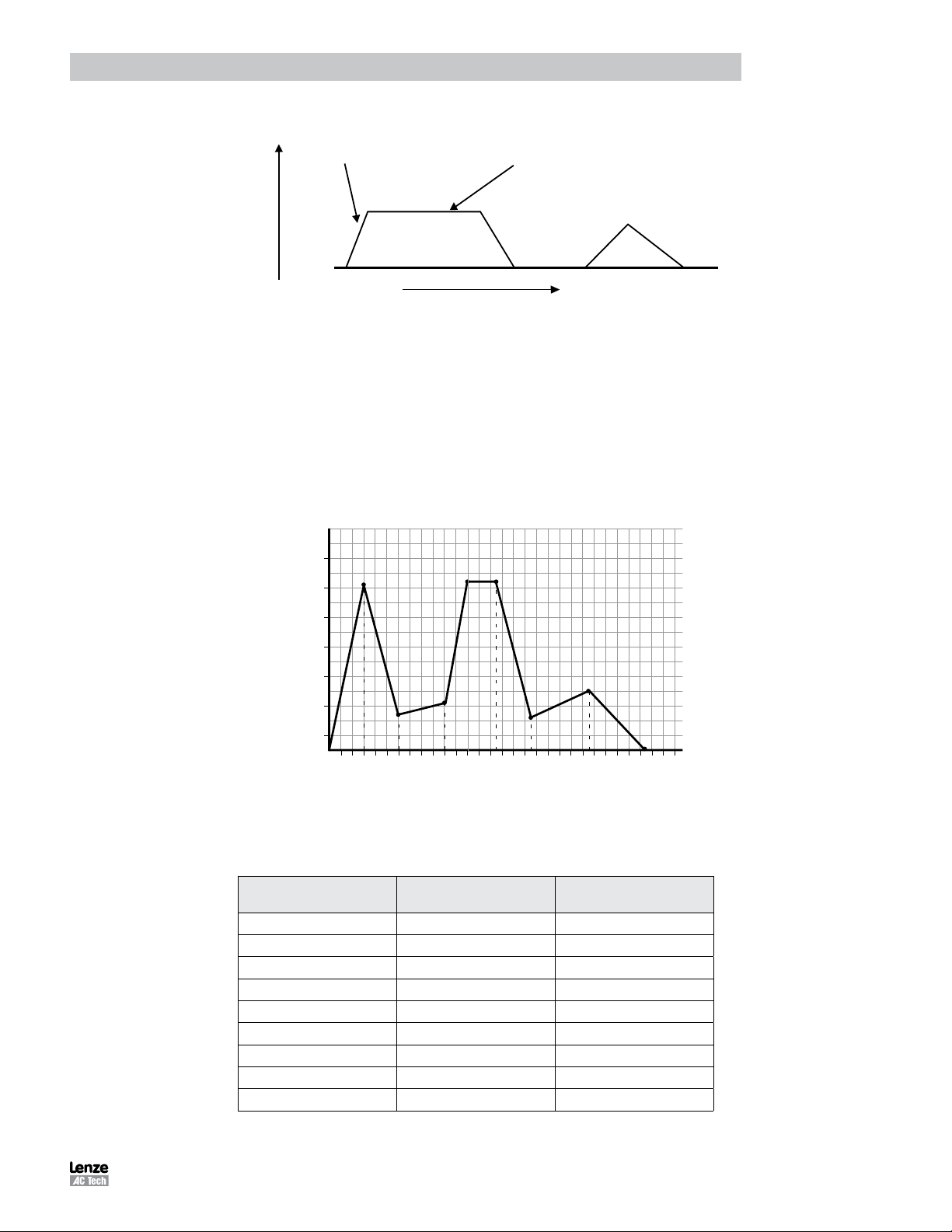
Introduction
Trapezoidal Move Profile
Velocity (RPS)
Current accel value
Velocity
Top Velocity
Triangular Move Profile
Time
Figure 10: Trapezoidal Move
1.10.3 Segment Moves
MOVED and MOVEP commands facilitate simple motion to be commanded, but if the required move profile is more
complex than a simple trapezoidal move, then the segment move MDV can be used.
The profile shown in Figure 11 is divided into 8 segments or 8 MDV moves. An MDV move (Move Distance Velocity) has
two arguments. The first argument is the distance moved in that segment. This distance is referenced from the motor’s
current position in User Units. The second argument is the desired target velocity for the end of the segment move. That
is the velocity at which the motor will run at the moment when the specified distance in this segment is completed.
70
60
Segment Number
50
40
30
20
10
Segment
1
Segment
2
Segment
3
5
Segment
5
Segment
4
10 15
Segment
6
Segment
Segment
7
20 25
8
Distance (User Units)
Figure 11: Segment Move
Table 7: Segment Move
Distance moved
during segment
1 3 56
2 3 12
3 4 16
4 2 57
5 2.5 57
6 3 11
7 5 20
8 5 0
- - -
Velocity at the end of
segment
30
PM94P01C 27
Page 30
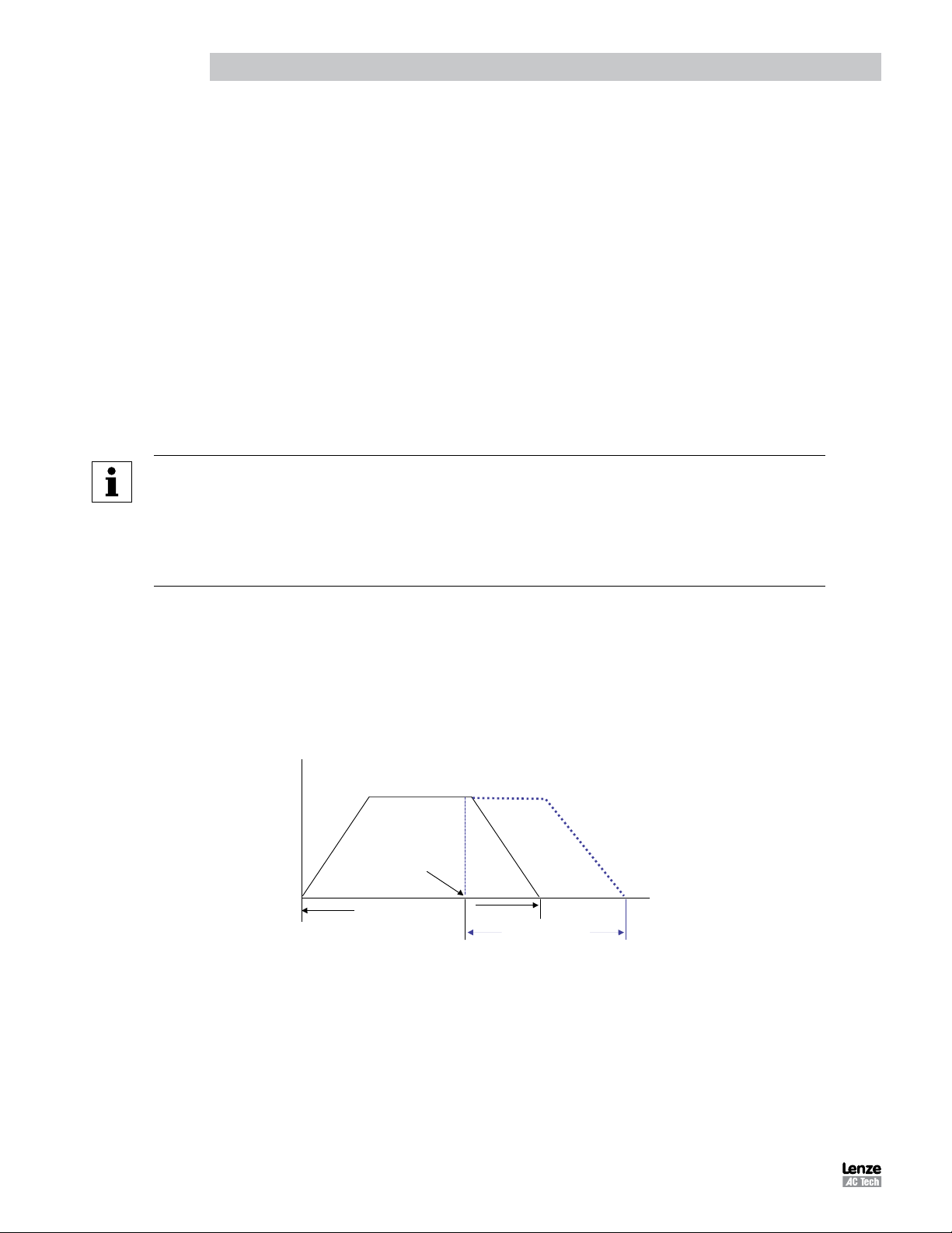
Introduction
Registration Move
Here is the user program for the segment move example. The last segment move must have a “0” for the end velocity,
(MDV 5 , 0). Otherwise, fault F_24 (Motion Queue Underflow), will occur.
;Segment moves
LOOP:
WAIT UNTIL IN_A4==0 ;Wait until input A4 is off before starting the move
MDV 3 , 56 ;Move 3 units accelerating to 56 User Units per sec
MDV 3 , 12 ;Move 3 units decelerating to 12 User Units per sec
MDV 4 , 16 ;Move 4 units accelerating to 16 User Units per sec
MDV 2 , 57 ;Move 2 units accelerating to 57 User Units per sec
MDV 2.5 , 57 ;Move 2.5 units maintaining 57 User Units per sec
MDV 3 , 11 ;Move 3 units decelerating to 11 User Units per sec
MDV 5 , 20 ;Move 5 units accelerating to 20 User Units per sec
MDV 5 , 0 ;Move 5 units decelerating to 0 User Units per sec
WAIT UNTIL IN_A4==1 ;Wait until input A4 is on before looping
GOTO LOOP
END
NOTE
When an MDV move is executed, the segment moves are stored to a Motion Queue. If the program
loops on itself, then the queue will become full and an F_23 Fault Motion Queue Overflow will
occur.
Since the MDV moves utilize a Motion Queue, the [Step] or [Step Over] debugging features can
not be used.
1.10.4 Registration
Both absolute and incremental moves can be used for registration moves. The statements associated with these moves
are MOVEPR and MOVEDR. These statements have two arguments. The first argument specifies the commanded
move distance or position. The second argument specifies the move made after the registration input is seen. If the
registration move is an absolute move, for MovePR, the first argument is absolute (referenced to the 0 position), the
second argument is relative to the registration position. For MoveDR, both arguments are relative. The first is relative to
the shaft position when motion is started and the second is relative to the registration position.
Position Registration
Input is made
Commanded
Move
Figure 12: Registration Move
Registration
Move
PM94P01C28
Page 31

Introduction
Velocity (RMS)
1.10.5 S-Curve Acceleration
Very often it is important for acceleration and deceleration of the motor to be as smooth as possible. For example,
using a smooth acceleration/deceleration profile could minimize the wear and tear on a machine tool, smoothing the
transition from accel/decel to steady state velocity. To perform smooth motion profiles, the PositionServo supports Scurve acceleration.
With normal straight line acceleration, the axis is accelerated to the target velocity in a linear fashion. With S-curve
acceleration, the motor accelerates slowly at the first, then twice as fast as the middle straight line area, and then slowly
stops accelerating as it reaches the target velocity. With straight line acceleration, the acceleration changes are abrupt
at the beginning of the acceleration and again once the motor reaches the target velocity. With S-curve acceleration,
the acceleration gradually builds to the peak value then gradually decreases to no acceleration. The disadvantage
with S-curve acceleration is that for the same acceleration distance the peak acceleration is twice that of straight line
acceleration, which often requires twice the peak torque. Note that the axis will arrive at the target position at the same
time regardless of which acceleration method is used.
T1
2
T
T1
2
T
Distance (Units)
Figure 13: Sequential Move
To use S-curve acceleration in a MOVED, MOVEP or MDV statement requires only the additional “,S” at the end of the
statement.
Examples:
MOVED 10 , S
MOVEP 10 , S
MDV 10,20,S
MDV 10,0,S
1.10.6 Motion Queue
The PositionServo drive executes the User Program one statement at a time. When a move statement (MOVED or
MOVEP) is executed, the move profile is stored to the Motion Queue. The program will, by default, wait on that statement
until the Motion Queue has executed the move. Once the move is completed, the next statement in the program will be
executed. By default motion commands (other than MDV statements) effectively suspend the program until the motion
is complete.
A standard move (MOVED or MOVEP) is only followed by one argument. This argument references the distance or
position to move the motor to. By adding the second argument “C”, (MOVEP 0,C) or (MOVED 100,C), the drive is
allowed to continue executing the user program during the move. At this point, multiple move profiles can be stored to
the queue. The Motion Queue can hold up to 32 profiles. The Continue “C” argument is very useful when it is necessary
to trigger an action, e.g. handle I/O, while the motor is in motion. Below the Pick and Place Example Program has been
modified to utilize the Continue, “C”, argument.
PM94P01C 29
Page 32

Introduction
;**************************** Main Program ********************************
PROGRAM_START: ;Place holder for main program loop
ENABLE ;Enable output from drive to motor
WAIT UNTIL IN_A4==1 ;Make sure Arm is retracted before starting the program
MOVEP 0 ;Move to position 0 to pick part
OUT1 = 1 ;Turn on output 1 to extend Pick arm
WAIT UNTIL IN_A1==1 ;Check input to make sure Arm is extended
OUT2 = 1 ;Turn on output 2 to Engage gripper
WAIT TIME 1000 ;Delay 1 sec to Pick part
OUT1 = 0 ;Turn off output 1 to Retract Pick arm
WAIT UNTIL IN_A4==1 ;Check input to make sure Arm is retracted
MOVED 100,C ;Move to Place position and continue code execution
WAIT UNTIL APOS >25 ;Wait until pos is greater than 25
OUT3 = 1 ;Turn on output 3 to spray part
WAIT UNTIL APOS >=75 ;Wait until pos is greater than or equal to 75
OUT3 = 0 ;Turn off output 3 to shut off spray guns
WAIT UNTIL APOS >=95 ;Wait until move is almost done before extending arm
OUT1 = 1 ;Turn on output 1 to extend Pick arm
WAIT UNTIL IN_A1==1 ;Check input to make sure Arm is extended
OUT2 =0 ;Turn off output 2 to Disengage gripper
WAIT TIME 1000 ;Delay 1 sec to Place part
OUT1 = 0 ;Retract Pick arm
WAIT UNTIL IN_A4==1 ;Check input to make sure Arm is retracted
GOTO PROGRAM_START ;Loop back and continuously execute main program loop
END
When the “C” argument is added to the standard MOVED and MOVEP statements, program execution is not interrupted by
the execution of the motion command. NOTE: With an MDV move the execution of the program is never suspended.
The generated motion profiles are stored directly to the Motion Queue and are then executed in sequence. If the
MOVED and MOVEP statements don’t have the “C” modifier, then the motion profiles generated by these statements
go to the motion stack and the program is suspended until each profile has been executed.
1.11 Subroutines and Loops
1.11.1 Subroutines
Often it is necessary to repeat a series of program statements in several places in a program. Subroutines can be useful
in such situations. The syntax of a subroutine is simple. Subroutines must be placed after the main program, i.e. after
the END statement, and must start with the subname: label (where subname is the name of subroutine), and must end
with a statement RETURN.
Note that there can be more than one RETURN statement in a subroutine. Subroutines are called using the GOSUB
statement.
PM94P01C30
Page 33

Introduction
1.11.2 Loops
SML language supports WHILE/ENDWHILE block statement which can be used to create conditional loops. Note that
IF-GOTO statements can also be used to create loops.
The following example illustrates calling subroutines as well as how to implement looping by utilizing WHILE / ENDWHILE
statements.
;*************************** Initialize and Set Variables ******************
UNITS = 1 ;Units in Revolutions (R)
ACCEL = 15 ;15 Rev per second per second (RPSS)
DECEL = 15 ;15 Rev per second per second (RPSS)
MAXV = 100 ;100 Rev per second (RPS)/6000RPM
APOS = 0 ;Set current position to 0 (absolute zero position)
DEFINE LOOPCOUNT V1
DEFINE LOOPS 10
DEFINE DIST V2
DEFINE REPETITIONS V3
REPETITIONS = 0
;******************************* Main Program ********************************
PROGRAM_START: ;Place holder for main program loop
ENABLE ;Enable output from drive to motor
MAINLOOP:
LOOPCOUNT=LOOPS ;Set up the loopcount to loop 10 times
DIST=10 ;Set distance to 10
WHILE LOOPCOUNT ;Loop while loopcount is greater than zero
DIST=DIST/2 ;decrease dist by 1/2
GOSUB MDS ;Call to subroutine
WAIT TIME 100 ;Delay executes after returned from the subroutine
LOOPCOUNT=LOOPCOUNT-1 ;decrement loop counter
ENDWHILE
REPETITIONS=REPETITIONS+1 ;outer loop
IF REPETITIONS < 5
GOTO MAINLOOP
Wait Motioncomplete ;Wait for MDV segments to be completed
ENDIF
END
;****************************** Sub-Routines ******************************
MDS:
V4=dist/3
MDV V4,10
MDV V4,10
MDV V4,0
RETURN
NOTE
Running this code as is will most likely result in F_23. There are 3 MDV statements that are
executed 10 times = 30 moves. Then the condition set on the repetitions variable makes the
program execute the above another 4 times. 4 x 30 = 120. The 120 moves, with no waits anywhere
in the program will most likely produce an F_23 fault (Motion Queue overflow).
PM94P01C 31
Page 34

Introduction
2. Programming
2.1 Program Structure
One of the most important aspects of programming is developing the program’s structure. Before writing a program, first
develop a plan for that program. What tasks must be performed? And in what order? What things can be done to make
the program easy to understand and allow it to be maintained by others? Are there any repetitive procedures?
Most programs are not a simple linear list of instructions where every instruction is executed in exactly the same order
each time the program runs. Programs need to do different things in response to external events and operator input.
SML contains program control structure instructions and scanned event functions that may be used to control the flow
of execution in an application program. Control structure instructions are the instructions that cause the program to
change the path of execution. Scanned events are instructions that execute at the same time as the main body of the
application program.
Header - Enter in program description and title information
;********************************* HEADER *********************************
;Title: Pick and Place example program
;Author: Lenze - AC Technology
;Description: This is a sample program showing a simple sequence that
; picks up a part, moves to a set position and places the part
I/O List - Define what I/O will be used
;********************************* I/O List ******************************
; Input A1 - not used
; Input A2 - not used
; Input A3 - Enable Input
; Input A4 - not used
; Input B1 - not used
; Input B2 - not used
; Input B3 - not used
; Input B4 - not used
; Input C1 - not used
; Input C2 - not used
; Input C3 - not used
; Input C4 - not used
;
; Output 1 - Pick Arm
; Output 2 - Gripper
; Output 3 - not used
; Output 4 - not used
Initialize and Set Variables - Define and assign variable values
;**************************** Initialize and Set Variables *****************
UNITS = 1
ACCEL = 75
DECEL =75
MAXV = 10
;V1 =
;V2 =
DEFINE Output_on 1
DEFINE Output_off 0
PM94P01C32
Page 35

Introduction
Events - Define Event name, Trigger and Program Statements
;***************************** Events **************************************
EVENT SPRAY_GUNS_ON APOS > V1 ;Event will trigger as position passes 25 in pos dir.
OUT3= Output_On ;Turn on the spray guns (out 3 on)
ENDEVENT ;End event
EVENT SPRAY_GUNS_OFF APOS > V2 ;Event will trigger as position passes 75 in pos dir.
OUT3= Output_Off ;Turn off the spray guns (out 3 off)
ENDEVENT ;End even
Main Program - Define the motion and I/O handling of the machine
;***************************** Main Program ********************************
RESET_DRIVE: ;Place holder for Fault Handler Routine
WAIT UNTIL IN_A3 ;Make sure that the ENABLE input is made before continuing
ENABLE ;Enable output from drive to motor
PROGRAM_START: ;Place holder for main program loop
EVENT SPRAY_GUNS_ON ON ;Enable the ‘spray guns on’ event
EVENT SPRAY_GUNS_OFF ON ;Enable the ‘spray guns off’ event
WAIT UNTIL IN_A4==1 ;Make sure Arm is retracted before starting the program
MOVEP 0 ;Move to position 0 to pick part
OUT1 = Output_On ;Turn on output 1 to extend Pick arm
WAIT UNTIL IN_A1==1 ;Check input to make sure Arm is extended
OUT2 = Output_On ;Turn on output 2 to Engage gripper
WAIT TIME 1000 ;Delay 1 sec to Pick part
OUT1 = Output_Off ;Turn off output 1 to Retract Pick arm
WAIT UNTIL IN_A4==1 ;Check input to make sure Arm is retracted
MOVED 100 ;Move to Place position
OUT1 = Output_On ;Turn on output 1 to extend Pick arm
WAIT UNTIL IN_A1==1 ;Check input to make sure Arm is extended
OUT2 = Output_Off ;Turn off output 2 to Disengage gripper
WAIT TIME 1000 ;Delay 1 sec to Place part
OUT1 = Output_Off ;Retract Pick arm
WAIT UNTIL IN_A4==1 ;Check input to make sure Arm is retracted
GOTO PROGRAM_START ;Loop back and continuously execute main program loop
END
Sub-Routine - Any and all Sub-Routine code should reside here
;************************* Sub-Routines ***********************************
; Enter Sub-Routine code here
Fault Handler - Define what the program should do when a fault is detected
;************************* Fault Handler Routine **************************
; Enter Fault Handler code here
ON FAULT
ENDFAULT
The header section of the program contains description information, program name, version number, description of
process and programmers name. The I/O List section of the program contains a listing of all the I/O used within the
application. The Initialize and Set Variables section of the program defines the names for the user variables and
constants used in the program and provides initial setting of these and other variables.
PM94P01C 33
Page 36

Programming
The Events section contains all scanned events. Remember to execute the EVENT <eventname> ON statement in
the main program to enable the events. Please note that not all of the SML statements are executable from within the
EVENT body. For more detail, reference “EVENT” and “ENDEVENT” in Section 3 of the manual. The GOTO statement
can not be executed from within the Event body. However, the JUMP statement can be used to jump to code in the main
program body. This technique allows the program flow to change based on the execution of an event. For more detail,
reference “JUMP”, in Section 3.1 (Program Statement Glossary) of this manual.
The main program body of the program contains the main part of the program, which can include all motion and math
statements, labels, I/O commands and subroutine calls. The main body should be finished with an END statement,
however if the program loops indefinitely then the END statement can be omitted.
Subroutines are routines that are called from the main body of the program. When a subroutine is called, (GOSUB), the
program’s execution is transferred from the main program to the called subroutine. It will then process the subroutine
until a RETURN statement occurs. Once a RETURN statement is executed, the program’s execution will return back to
the main program to the line of code immediately following the GOSUB statement.
Fault handler is a section of code that is executed when the drive detects a fault. This section of code begins with the
“ON FAULT” statement and ends with an “ENDFAULT” statement. When a fault occurs, the normal program flow is
interrupted, motion is stopped, the drive is disabled, Event scanning is stopped and the statements in the Fault Handler
are executed, until the program exits the fault handler. The Fault handler can be exited in two ways:
- The “RESUME” statement will cause the program to end the Fault Handler routine and resume the execution of the main program. The location (label) called out in the “RESUME” command will determine where the
program will commence.
- The “ENDFAULT” statement will cause the user program to be terminated.
While the Fault Handler is being executed, Events are not being processed and detection of
additional faults is not possible. Because of this, the Fault Handler code should be kept as
short as possible.
If extensive code must be written to process the fault, then this code should be placed in the
main program and the “RESUME” statement should be utilized. Not all of SML statements
can be utilized by the Fault Handler. For more details reference “ON FAULT/ENDFAULT”,
in Section 3.1 (Program Statement Glossary) of this manual.
Comments are allowed in any section of the program and are preceded by a semicolon. They may occur on the
same line as an instruction or on a line by themselves. Any text following a semicolon in a line will be ignored by the
compiler.
2.2 Variables
Variables can be System or User. User variables do not have a predefined meaning and are available to the user
to store any valid numeric value. System variables have a predefined meaning and are used to configure, control or
monitor the operations of the PositionServo. (Refer to paragraph 2.6 for more information on System Variables).
All variables can be used in valid arithmetic expressions. All variables have their own corresponding index or identification
number. Any variable can be accessed by their identification number from the User’s program or from a Host Interface.
In addition to numbers some of the variables have predefined names and can be accessed by that name from the User’s
program.
The following syntax is used when accessing variables by their identification number:
@102 = 20 ; set variable #102 to 20
@88=@100 ; copy value of variable #100 to variable #88
Variable @102 has the variable name ‘V2”; variable @88 has the variable name ‘VAR_AOUT’ and variable @100 has
the variable name ‘V0’. Hence the program statements above could be written as:
V2 = 20
VAR_AOUT = V0
PM94P01C34
Page 37

Programming
There are two types of variables in the PositionServo drive - User Variables and System Variables.
User Variables are a fixed set of variables that the programmer can use to store data and perform arithmetic
manipulations. All variables are of a single type. Single type variables, i.e. typeless variables, relieve the programmer of
the task of remembering to apply conversion rules between types, thus greatly simplifying programming.
User Variables
V0-V31 User defined variables. Variables can hold any numeric value including logic (Boolean 0 - FALSE and
non 0 - TRUE) values. They can be used in any valid arithmetic or logical expressions.
NV0-NV31 User defined network variables. Variables can hold any numeric value including logic (Boolean 0
- FALSE and non 0 - TRUE) values. They can be used in any valid arithmetic or logical expressions.
Variables can be shared across Ethernet network with use of statements SEND and SENDTO.
Since SML is a typeless language, there is no special type for Boolean type variables (variables that can be only 0 or
1). Regular variables are used to facilitate Boolean variables. Assigning a variable a “FALSE” state is done by setting it
equal to “0”. Assigning a variable a “TRUE” state is done by assigning it any value other than “0”.
Scope
SML variables are accessible from several sources. Each of the variables can be read and set from any user program
or Host communications interface at any time. There is no provision to protect a variable from change. This is referred
to as global scope.
Volatility
User variables are volatile i.e. they don’t maintain their values after the drive is powered down. After power up the values
of the user variables are set to 0. Loading or resetting the program doesn’t change variables values.
In addition to the user variables, system variables are also provided. System variables are dedicated variables that
contain specific information relative to the setup and operation of the drive. For example, APOS variable holds actual
position of the motor shaft. For more details refer to Section 2.9.
Flags, Resolution and Accuracy
Any variable can be used as a flag in a logical expression and as a condition in a conditional expression. Flags are often
used to indicate that some event has occurred, logic state of an input has changed or that the program has executed to
a particular point. Variables with non ‘0’ values are evaluated as “TRUE” and variables with a “0” values are evaluated
as “FALSE”.
Variables are stored internally as 4 bytes (double word) for integer portion and 4 bytes (double word) for fractional
portion. Every variable in the system is stored as 64 bit in 32.32 fixed point format. Maximum number can be represented
by this format is +/- 2,147,483,648. Variable resolution in this format is 2.3E-10.
PM94P01C 35
Page 38

Programming
2.3 Arithmetic Expressions
Table 8 lists the four arithmetic functions supported by the Indexer program. Constants as well as User and System
variables can be part of the arithmetic expressions.
Examples.
V1 = V1+V2 ;Add two user variables
V1 = V1-1 ;Subtract constant from variable
V2 = V1+APOS ;Add User and System (actual position) variables
APOS = 20 ;Set System variable
V5 = V1*(V2+V3*5/2+1) ;Complicated expression
Table 8: Supported Arithmetic Expressions
Operator Symbol
Addition +
Subtraction -
Multiplication *
Division /
Result overflow for “*” and “/” operations will cause arithmetic overflow fault F_19. Result overflow/underflow for “+” and
“-” operations does not cause an arithmetic fault.
2.4 Logical Expressions and Operators
Bitwise, Boolean, and comparison operators are considered as Logical Operators. They operate on logical values of the
operands. There are two possible values for logical operand: TRUE and FALSE. Any value contained in a User variable,
System variable or flag is treated as TRUE or FALSE with these types of the operators. If a variable value equals “0”, it
is considered FALSE. All other values (non-0) including negative numbers are considered TRUE.
2.4.1 Bitwise Operators
Table 9 lists the bitwise operators supported by the Indexer program.
Table 9: Supported Bitwise Operators
Operator Symbol
AND &
OR |
XOR ^
NOT !
Both User or System variables can be used with these operators. In order to perform a bitwise (Boolean) operation, the
value must be referenced in hexadecimal format. Example: bit 22 alone would be referenced as 0x400000.
Examples:
V1 = V2 & 0xF ;clear all bits but lowest 4
IF (INPUTS & 0x3) ;check inputs 0 and 1
V1 = V1 | 0xff ;set lowest 8 bits
V1 = INPUTS ^ 0xF ;invert inputs 0-3
V1 = !IN_A1 ;invert input A1
PM94P01C36
Page 39

Programming
2.4.2 Boolean Operators
Table 10 lists the boolean operators supported by the Indexer program. Boolean operators are used in logical
expressions.
Table 10: Supported Boolean Operators
Operator Symbol
AND &&
OR ||
NOT !
Examples:
IF APOS >2 && APOS <6 || APOS >10 && APOS <20
{statements if true}
ENDIF
The above example checks if APOS (actual position) is within one of two windows; 2 to 6 units or 10 to 20 units.
In other words:
If (APOS is more than 2 AND less than 6)
OR
If (APOS is more than 10 AND less then 20)
THEN the logical expression is evaluated to TRUE. Otherwise it is FALSE
2.5 Comparison Operators
Table 11 lists the comparison operators supported by the Indexer program.
Table 11: Supported Comparison Operators
Operator Symbol
More >
Less <
Equal or more >=
Equal or less =<
Not Equal <>
Equal ==
Examples:
IF APOS <=10 ; If Actual Position equal or less than 10
IF APOS > 20 ; If Actual Position greater than 20
IF V0 ==5 ; If V0 equal to 5
IF V1<2 && V2 <>4 ; If V1 less than 2 and V2 doesn’t equal 4
PM94P01C 37
Page 40

Programming
2.6 System Variables and Flags
System variables are variables that have a predefined meaning. They give the programmer/user access to drive
parameters and functions. Some of these variables can also be set via the parameters in MotionView. In most cases
the value of these variables can be read and set in your program or via a Host Interface. Variables are either read only,
write only or read and write. Read only variables can only be read and can’t be set. For example, INPUTS = 5, is an
illegal action because you can not set an input. Conversely, write-only variables cannot be read. Reading a write-only
variable by either the variable watch window or network communications can result in erroneous data.
System Flags are System Variables that can only have values of 0 or 1. For example, IN_A1 is the system flag that
reflects the state of digital input A1. Since inputs can only be ON or OFF, then the value of IN_A1 can only be 0 or 1.
2.7 System Variables Storage Organization
All system variables are located in drive’s RAM memory and therefore are volatile. However, values for some of these
system variables are also stored in EPM. When a system variable is changed in MotionView, its value changes in both
RAM and EPM. When a system variable is changed from the user’s program, its value is changed in RAM only and will
be lost on power down.
Host interfaces have the capability to change the variable value in both the EPM and RAM. The user has a choice in
memory to change a variable in RAM and EPM or in RAM only.
2.7.1 RAM File for User’s Data Storage
In addition to the standard user variables (V0-V31 & NV0-NV31) PositionServo drives have a section of RAM memory
(256k) allocated as data storage space and available to the programmer for storage of program data.
The RAM file data storage is often required in systems where it is desirable to store large amounts of data prepared by
a host controller ( PLC, HMI, PC, etc). This data might represent more complex Pick and Place coordinates, complicated
trajectory coordinates, or sets of gains/limits specific for given motion segments.
RAM memory is also utilized in applications that require data collection during system operation. At the end of a period
of time the collected data can be acquired by the host controller for analysis. For example, position errors and phase
currents collected during the move are then analyzed by the host PLC/PC to qualify system tolerance to error free
operation.
Implementation
There are 256K (262,144) bytes provided as RAM file for data storage. Since the basic data type in the drive is 64 bit
(8 bytes) 32,768 data elements can be stored in the RAM file. The file is accessible from within the User’s program
or through any external communications interface (Ethernet, ModBUs, CAN etc.). Two statements and three system
variables are provided for accessing the RAM file memory. The RAM file is volatile storage and is intended for “per
session” usage. The data saved in the RAM file will be lost when the drive is powered off.
The three system variables provided to support file access are:
VAR_MEM_VALUE (PID = 4)
VAR_MEM_INDEX (PID = 5)
VAR_MEM_INDEX_INCREMENT (PID = 6)
In addition, two statements are provided to to allow access and storage to the RAM file direct from convenient statements
within the user program. The statements MEMSET, MEMGET are described in paragraph 2.7.3 and Tables 44 & 45.
PM94P01C38
Page 41

Programming
2.7.2 Memory Access Through Special System Variables
MEM_INDEX holds the value that will be read or written to the RAM file. MEM_INDEX points to the position in the RAM
file (0 to 32767) and MEM_INDEX_INCREMENT holds the value that MEM_INDEX is going to modify after the read or
write operation is completed.
The RAM memory access is illustrated with the example program herein.
;--------------------------------------------------------------------------;User’s program to read/write to RAM file.
;Advance index after writing/reading by 1
;Record position error to RAM file every 100 ms for 10 seconds. 10/0.1 = 100
;locations are needed
;---------------------------------------------------------------------------
#DEFINE IndexStart 0
#DEFINE MemIncrement 1
#DEFINE RecordLength 100
#DEFINE PElimit 0.1 ;0.1 user unit
VAR_MEM_INDEX = IndexStart ;set start position
VAR_MEM_INDEX_INCREMENT=MemIncrement ;set increment
;--------------------------------------------------------------------------EVENT StorePE TIME 100
VAR_MEM_VALUE = VAR_POSERROR ;store in RAM file.
ENDEVENT
PROGRAMSTART:
EVENT StorePE ON
{
Start some motion activity….
}
;wait for data collection is over
WHILE VAR_MEM_INDEX < (IndexStart+RecordLength)
ENDWHILE
EVENT StorePE Off ;turn off storage
;Analyze data collected. If PE > PElimit then signal system has low performance…
VAR_MEM_INDEX= IndexStart
WHILE VAR_MEM_INDEX < (IndexStart+RecordLength)
IF (VAR_MEM_VALUE > PElimit)
GOTO Label_SignalBad
ENDIF
ENDWHILE
LabelSignalBad:
{
Signal that PE out of limits
…
}
END
PM94P01C 39
Page 42

Programming
In the RAM memory access program example, the values of PE (position error) are stored sequentially in the RAM
file every 100ms for 10 seconds. (100 samples). After collection is done the data is read from the file one by one and
compared with limit.
Variable VAR_MEM_INDEX is incremented every read or write by the value stored in VAR_MEM_INDEX_INCREMENT.
That value could be any value from -32767 to 32767. This way backwards reading is also possible. If the value is 0
(zero) no increment/decrement is produced. VAR_MEM_INDEX wraps around its min/max values. I.e. if the next read
or write will result in a value more (less) than 32767 (-32767), the index will be adjusted by modulo 32767. This allows
for the creation of circular arrays. This feature can be used for diagnostics when certain parameter(s) are stored in the
memory continuously and then if the system fails the data array can be examined to simplify diagnostics.
2.7.3 Memory Access Through MEMSET, MEMGET Statements
The memory access statements MEMSET and MEMGET are provided for simplified storage of data in the RAM memory
to/from the user variables V0-V31. Using these statements any combinations of variables V0-V31 can be stored/retrieved
with a single statement. This allows for efficient access to the RAM memory area. For example, in reading 10 variables
of the user’s program. Indeed for reading 10 variables V0-V10 it would normally require 10 read statements (Vx=VAR_
MEM_VALUE). With the MEMGET statement all V0-V10 can be read in one step. The format of MEMSET/MEMGET is
as follows:
MEMSET <offset> [ <varlist>]
MEMGET <offset> [ <varlist>]
<offset> any valid expression that evaluates to a number between -32767 to 32767
It specifies the offset in the RAM file where data will be stored or retrieved.
<varlist> any combinations of variables V0-V31
Examples for <offset> expression
5 constant
10+23+1 constant expression
V0 variable Must hold values in -32767 to 32767 range
V0+V1+3 expression Must evaluate to -32767 to 32767 range
Example: <offset> =5
RAM file memory
0 1 2 3 4 5 6 ... address increase
data data data data data data data
Examples for <varlist> instruction
[V0] single variable will be stored/retreived
[V0,V3,V2] variables V0,V3,V2 will be stored/retrieved
[V3-V7] variables V3 to V7 inclusively will be stored
[V0,V2,V4-V8] variables V0,V2, V4 through V8 will be stored
Storage/Retrieval order with MEMSET/MEMGET
Variables in the list are always stored in order: the variable with smallest index first and the variables with highest index
last regardless of the order they appear in the <varlist> instruction.
Example: [V0,V3, V5-V7] will be stored in memory in the order of increasing memory index as follows:
RAM file memory
V0 V3 V5 V6 V7 ... ... ... index increase
For comparison: [V5-V7, V0, V3] will have the same storage order as the above list regardless of the order in which the
variables are listed.
PM94P01C40
Page 43

Programming
When retrieving data with MEMGET statements memory locations will be sequentially copied to variables starting from
the one with smallest index in the list to the last with biggest index. Consider the list for the MEMGET statement:
[V2,V3,V5-V7]
RAM file memory
Data1 Data2 Data3 Data4 Data5 Data6 ... ... index increase
Here is how the data will be assigned to variables:
V2 <- Data1
V3 <- Data2
V5 <- Data3
V6 <- Data4
V7 <- Data5
2.8 System Variables and Flags Summary
2.8.1 System Variables
Section 3.2 provides a complete list of the system variables. Every aspect of the PositionServo can be controlled by
the manipulation of the values stored in the System Variables. All System Variables start with a “VAR_” followed by the
variable name. Alternatively, System Variables can be addressed as an @NUMBER where the number is the variable
Index. The most frequently used variables also have alternate names listed in Table 12.
Table 12: System Variables
Index Variable Access Variable Description Units
181 ACCEL R/W Acceleration for motion commands User Units/Sec
71 AIN1 R Analog input. Scaled in volts. Range from -10 to +10 volts V(olt)
72 AIN2 R Analog input 2. Scaled in Volts. Range from -10 to +10 volts V(olt)
(2)
88 AOUT R/W Analog output. Value in Volts. Valid range from -10 to +10 (V)
215 APOS R/W Actual motor position User Units
190 APOS_PLS R/W Actual Motor Position Encoder Counts
182 DECEL R/W Deceleration for motion commands User Units/Sec
83 DEXSTATUS R Drive Extended Status Word -
54 DSTATUS R Status flags register -
DFAULTS R Fault code register -
245 HOME W Start Homing (pre-defined homing) -
INDEX R Lower 8 bits are used. See ASSIGN statement for details. -
184 INPOSLIM R/W Maximum deviation of position for INPOSITION Flag to remain set User Units
65 INPUTS R Digital Inputs states. The first 12 bits correspond to the 12 drive inputs -
139 IREF W Internal Reference: Velocity / Torque RPS/A
187 MECOUNTER R Master Encoder Counts (Master Encoder Input) Encoder Counts
180 MAXV R/W Maximum velocity for motion commands User Units/Sec
140-
171
66 OUTPUTS R/W Digital outputs. Bits #0 to #4 represent outputs 1 through 5 -
216 PERROR R Position Error Feedback Pls
191 PERROR_PLS R Position Error User Units
48 PGAIN_D R/W Position loop D-gain -
47 PGAIN_I R/W Position loop I-gain -
49 PGAIN_ILIM R/W Position loop I gain limit -
46 PGAIN_P R/W Position loop P-gain -
NV0 - NV31 R/W User Network Variables -
V(olt)
2
2
PM94P01C 41
Page 44

Programming
Index Variable Access Variable Description Units
188 PHCUR R Motor phase current A(mpere)
183 QDECEL R/W Quick Deceleration for STOP MOTION QUICK statement User Units/Sec
213 RPOS R Registration position. Valid when system flag F_REGISTRATION set User Units
212 RPOS_PLS R Registration position Feedback Pls
218 TA R Commanded acceleration User units/Sec
214 TPOS R/W Theoretical/commanded position User Units
219 TPOS_ADV W Theoretical/commanded position advance Feedback Pls
189 TPOS_PLS R/W Theoretical/commanded position Feedback Pls
217 TV R Commanded velocity in User Units/Sec
(1)
186 UNITS R/W User Units scale.
185 VEL R/W Set Velocity when in velocity mode User Units/Sec
44 VGAIN_P R/W Velocity loop P-gain -
45 VGAIN_I R/W Velocity loop I-gain -
100-
131
(1)
When a “0”, (Zero), value is assigned to the variable “UNITS”, then “USER UNITS” is set to QUAD ENCODER COUNTS. This is the default setting
at the start of the program before UNITS=<value> is executed.
(2)
Any value outside +/- 10 range assigned to AOUT will be automatically trimmed to that range
V0 - V31 R/W User Variables
UserUnits/Rev
2
2
Example:
AOUT=100 , AOUT will be assigned value of 10.
V0=236
VOUT=V0, VOUT will be assigned 10 and V0 will be unchanged.
2.8.2 System Flags
Flags don’t have an Index number assigned to them. They are the product of a BIT mask applied to a particular system
variable by the drive and are available to the user only from the User’s program. Table 13 lists the System Flags with
access rights and description.
Table 13: System Flags
Name Access Description
IN_A1-4, IN_B1-4, IN_C1-4 R Digital inputs . TRUE if input active, FALSE otherwise
OUT1, OUT2, OUT3, OUT4, OUT5 W Digital outputs OUTPUT1- OUTPUT5
F_ICONTROL OFF R Interface Control Status (ON/OFF) #27 in DSTATUS register
F_IN_POSITION R
F_ENABLED R Set when drive is enabled
F_EVENTS OFF R Events Disabled Status (ON/OFF) #30 in DSTATUS register
F_MCOMPLETE R
F_MQUEUE_FULL R Motion Queue full
F_MQUEUE_EMPTY R Motion Queue empty
F_FAULT R Set if any fault detected
F_ARITHMETIC_FLT R Arithmetic fault
F_REGISTRATION R
F_MSUSPENDED R Set if motion suspended by statement MOTION SUSPEND
TRUE when Actual Position (APOS) is within limits set by
INPOSLIM variable and motion completed
Set when motion is completed and there is no motion commands
waiting in the Motion Queue
Set when registration mark was detected. Content RPOS variable is
valid when this flag is active. Flag resets by any registration moves
MOVEPR,MOVEDR or by command REGISTRATION ON
PM94P01C42
Page 45

Programming
Flag logic is shown herein.
IF
TPOS-INPOSLIM < APOS < TPOS+INPOSLIM && F_MCOMPLETE && F_MQUEUE_EMPTY
F_IN_POSITION = TRUE
ELSE
F_IN_POSITION = FALSE
ENDIF
For VELOCITY mode F_MCOMPLETE and F_MQUEUE_EMPTY flags are ignored and assumed TRUE.
2.9 Control Structures
Control structures allow the user to control the flow of the program’s execution. Most of the power and utility of any
programming language comes from its ability to change statement order with structure and loops.
2.9.1 DO/UNTIL Structure
This statement is used to execute a block of code one time and then continue executing that block until a condition
becomes true (satisfied). The difference between DO/UNTIL and WHILE statements is that the DO/UNTIL instruction
tests the condition after the block is executed so the conditional statements are always executed at least one time. The
syntax for DO/UNTIL statement is:
DO
…statements
UNTIL <condition>
The flowchart and code segment in Figure 14 illustrate the use of the DO/UNTIL statement.
Start
… statements
Move DIstance 3
units. Delay 2
seconds
NO
DO
MOVED 3
WAIT TIME 2000
UNTIL IN_A3
Is input A3 ON?
…statements
YES
End
Figure 14: DO/UNTIL Code and Flowchart
2.9.2 WHILE Structure
This statement is used if you want a block of code to execute while a condition is true.
WHILE <condition>
…statements
ENDWHILE
PM94P01C 43
Page 46

Programming
The flowchart and code segment in Figure 15 illustrate the syntax for the WHILE instruction.
WHILE <condition>
Start
…statements
ENDWHILE
NO
Is input A3 ON?
…statements
WHILE IN_A3
MOVED 3
WAIT TIME 2000
ENDWHILE
…statements
Move DIstance 3
YES
units. Delay 2
seconds
End
Figure 15: WHILE Code and Flowchart
2.9.3 Subroutines
A subroutine is a group of SML statements that is located at the end of the main body of the program. It starts with a
label which is used by the GOSUB statement to call the subroutine and ends with a RETURN statement. The subroutine
is executed by using the GOSUB statement in the main body of the program. Subroutines can not be called from an
EVENT or from the FAULT handlers.
When a GOSUB statement is executed, execution is transferred to the first line of the subroutine. The subroutine is
then executed until a RETURN statement is met. When the RETURN statement is executed, the program’s execution
returns to the program line, in the main program, following the GOSUB statement. Subroutines may have more than
one RETURN statement in its body.
Subroutines may be nested up to 32 times. Only the main body of the program and subroutines may contain a GOSUB
statement. Refer to Section 3.1 for more detailed information on the GOSUB and RETURN statements. The flowchart
and code segment in Figure 16 illustrate the use of subroutines.
…statements
GOSUB CalcMotionParam
Start
MOVED V1
OUT2=1
…statements
Main Program
END
;Subs usually located after END
GOSUB
;statement of main program
;
Label
CalcMotionParam:
V1 = (V3*2)/V4
RETURN
RETURN
End
Figure 16: GOSUB Code and Flowchart
PM94P01C44
Page 47

Programming
2.9.4 IF Structure
The “IF” statement is used to execute an instruction or block of instructions one time if a condition is true. The simplified
syntax for the IF statement is:
IF condition
…statement(s)
ENDIF
The flowchart and code segment in Figure 17 illustrate the use of the IF statement.
Start
…statements
IF IN_A2
OUT2 = 1
MOVED 3
ENDIF
Input A2 ON?
NO
Yes
Set Output 2 ON
Move Distance 3
units
..statements
End
Figure 17: IF Code and Flowchart
2.9.5 IF/ELSE Structure
The IF/ELSE statement is used to execute a statement or a block of statements one time if a condition is true and a
different statement or block of statements if condition is false.
The simplified syntax for the IF/ELSE statement is:
IF <condition>
…statement(s)
ELSE
…statement(s)
ENDIF
The flowchart and code segment in Figure 18 illustrate the use of the IF/ELSE instruction.
…statements
IF IN_A2
OUT2=1
MOVED 3
ELSE
OUT2=0
MOVED 5
ENDIF
..statements
Figure 18: IF/ELSE Code and Flowchart
Start
Input A2 ON?
No
Set Output 2 OFF
Move Distance 5
units
End
PM94P01C 45
Yes
Set Output 2 ON
Move Distance 3
units
Page 48

Programming
2.9.6 WAIT Statement
The WAIT statement is used to suspend program execution until or while a condition is true, for a specified time period
(delay) or until motion has been completed. The simplified syntax for the WAIT statement is:
WAIT UNTIL <condition>
WAIT WHILE <condition>
WAIT TIME <time>
WAIT MOTION COMPLETE
2.9.7 GOTO Statement & Labels
The GOTO statement can be used to transfer program execution to a new point marked by a label. This statement is
often used as the action of an IF statement. The destination label may be above or below the GOTO statement in the
application program.
Labels may be any alphanumeric string 64 characters in length beginning with a letter and ending with a colon “:”.
GOTO TestInputs
…statements
TestInputs:
…statements
IF (IN_A1) GOTO TestInputs
Table 14 provides a short description of the instructions used for program branching.
Table 14: Program Branching Instructions
Name Description
GOTO Transfer code execution to a new line marked by a label
DO/UNTIL Do once and keep doing until conditions becomes true
IF and IF/ELSE Execute if condition is true
RETURN Return from subroutine
WAIT Wait fixed time or until condition is true
WHILE Execute while a condition is true
GOSUB Go to subroutine
2.10 Scanned Event Statements
A Scanned Event is a small program that runs independently of the main program. SCANNED EVENTS are very useful
when it is necessary to trigger an action , i.e. handle I/O, while the motor is in motion. When setting up Events, the first
step is to define both the action that will trigger the event as well as the sequence of statements to be executed once the
event has been triggered. Events are scanned every 512µs. Before an Event can be scanned however it must first be
enabled. Events can be enabled or disabled from the user program, from another event or from itself (see explanations
below). Once the Event is defined and enabled, the Event will be constantly scanned until the trigger condition is met,
this scan rate is independent of the main program’s timing. Once the trigger condition is met, the Event statements will
be executed independently of the user program.
Scanned events are used to record events and perform actions independent of the main body of the program. For
example, if you want output 3 to come ON when the position is greater than 4 units, or if you need to turn output 4 ON
whenever input 2 and 3 are ON, you may use the following scanned event statements.
EVENT PositionIndicator APOS > 4
OUT3=1
ENDEVENT
EVENT Inputs3and4 IN_A4 & IN_B1
OUT4=1
ENDEVENT
PM94P01C46
Page 49

Programming
Scanned events may also be used with a timer to perform an action on the periodic time basis.
The program statements contained in the action portion of the scanned event can be any legal program statement except
the following statements: Subroutine calls (GOSUB), DO/WHILE, WHILE, WAIT, GOTO and also motion commands:
MOVED,MOVEP, MDV, STOP, MOTION SUSPEND/RESUME.
EVENT <name> INPUT <inputname> RISE
This scanned event statement is used to execute a block of code each time a specified input <inputname> changes its
state from low to high.
EVENT <name> INPUT <inputname> FALL
This scanned event statement is used to execute a block of code each time a specified input <inputname> changes its
state from high to low.
EVENT <name> TIME <timeout>
This scanned event statement is used to execute a block of code with a repetition rate specified by the <timeout>
argument. The range for “timeout” is 0 - 50,000ms (milliseconds). Specifying a timeout period of 0 ms will result in the
event running every event cycle (256ms).
EVENT <name> expression
This scanned event statement is used to execute a block of code when the expression evaluates as true.
EVENT <name> ON/OFF
This statement is used to enable/disable a scanned event. Statement can be used within event’s block of code.
Scanned Event Statements Summary
Table 15 contains a summary of instructions that relate to scanned events. Refer to Section 3 “Language Reference”
for more detailed information.
Table 15: Scanned Events Instructions
Name Description
EVENT <name> ON/OFF enable / disable event
EVENT <name> INPUT <inputname> RISE Scanned event when <input name> goes low to high
EVENT <name> INPUT <inputname> FALL Scanned event when <input name> goes high to low
EVENT <name> TIME <value> Periodic event with <input name> repetition rate.
EVENT <name> expression Scanned event on expression = true
PM94P01C 47
Page 50

Programming
2.11 Motion
2.11.1 How Moves Work
The position command that causes motion to be generated comes from the profile generator or profiler for short.
The profile generator is used by the MOVE, MOVED, MOVEP, MOVEPR, MOVEDR and MDV statements. MOVE
commands generate motion in a positive or negative direction, while or until certain conditions are met. For example
you can specify a motion while a specific input remains ON (or OFF). MOVEP generates a move to specific absolute
position. MOVED generates incremental distance moves, i.e. move some distance from its current position. MOVEPR
and MOVEDR are registration moves. MDV commands are used to generate complicated profiles. Profiles generated
by these commands are put into the motion stack which is 32 levels deep. By default when one of these statements
(except for MDV) is executed, the execution of the main User Program is suspended until the generated motion is
completed. Motion requests generated by an MDV statement or MOVE statement with the “C” modifier do not suspend
the program. All motion statements are put into the motion stack and executed by the profiler in the order in which they
where loaded. The Motion Stack can hold up to 32 moves. The SML language allows the programmer to load moves
into the stack and continue on with the program. It is the responsibility of the programmer to check the motion stack
to make sure there is room available before loading new moves. This is done by checking the appropriate bits in the
System status register or the appropriate system flag.
2.11.2 Incremental (MOVED) and Absolute (MOVEP) Motion
MOVED and MOVEP statements are used to create incremental and absolute moves respectively. The motion that
results from these commands is by default a trapezoidal velocity move or an S-curved velocity move if the “,S” modifier
is used with the statement,
For example:
MOVEP 10 ;will result in a trapezoidal move
But
MOVEP 10,S ;will result in an S-curved move
In the above example, (MOVEP 10), the length of the move is determined by the argument following the MOVEP
command, (10). This argument can be a number, a variable or any valid arithmetic expression. The maximum velocity
of the move is determined by setting the system variable MAXV. The acceleration and deceleration are determined by
setting the system variables ACCEL and DECEL respectively.
If values for velocity, acceleration and deceleration, for a specified distance, are such that there is not enough time to
accelerate to the specified velocity, the motion profile will result in triangular or double S profile as illustrated in Figure
19.
PM94P01C48
Page 51

Programming
MOVE 1 MOVE 2
Velocity
Velocity = 20
Move1- 4 units
Time
Velocity
max velocity < 20
Move2 - 1.5 units
Time
Trapezoidal moves
MOVE 3 MOVE 4
Velocity
Velocity = 20
Move3- 4 units
Time
Velocity
max velocity < 20
Move4 - 1.5 units
Time
S-curve moves
Figure 19: Move Illustration
ACCEL = 200
DECEL = 200
MAXV = 20
MOVED 4 ;Move 1
MOVED 1.5 ;Move 2
MOVED 4 , S ;Move 3
MOVED 1.5 , S ;Move 4
All four of the moves shown in Figure 19 have the same Acceleration, Deceleration and Max Velocity values. Moves 1
and 3 have a larger value for the move distance than Moves 2 and 4. In Moves 1 and 3 the distance is long enough to
allow the motor to accelerate to the profiled max velocity and maintain that velocity before decelerating down to a stop.
In Moves 2 and 4 the distance is so small that while the motor is accelerating towards the profiled Max Velocity it has to
decelerate to a stop before it can ever obtain the profiled Max Velocity.
2.11.3 Incremental (MOVED) Motion
Incremental motion is defined as a move of some distance from the current position. ‘Move four revolutions from the
current position’ is an example of an incremental move.
MOVED is the statement used to create incremental moves. The simplified syntax is:
MOVED <+/-distance>
+/- sign will tell the motor shaft what direction to move.
2.11.4 Absolute (MOVEP) Move
Absolute motion is defined as a motion to some fixed position from the current position. The fixed position is defined
as a position relative to a fixed zero point. The zero point for a system is normally established during the homing cycle,
typically performed immediately after power-up.
During a homing cycle, the motor will make incremental moves while checking for a physical input, index mark, or
both.
PM94P01C 49
Page 52

Programming
2.11.5 Registration (MOVEDR MOVEPR) Moves
MOVEPR and MOVEDR are used to move to position or distance respectively just like MOVEP and MOVED. The
difference is that while the statements are being executed they are looking for a registration signal or registration input
(C3). If during the motion a registration signal is detected, then a new end position is generated. With both the MoveDR
and MovePR statements the drive will increment the distance called out in the registration argument. This increment will
be referenced from the position where the registration input has seen.
Example:
MOVEDR 5, 1 ;Statement move a distance of 5 user units or registration position +
;1 user units if registration input is activated during motion.
There are two exceptions to this behavior:
Exception one:
The move will not be modified to “Registration position +displacement” if the registration was detected while system was decelerating to complete the motion.
Exception two:
Once the registration input is seen, there must be enough room for the motor to decelerate to a stop using the
profiled Decel Value. If the new registration move is smaller than the distance necessary to come to a stop, then
the motor will overshoot the new registration position.
2.11.6 Segment Moves
In addition to the simple moves that can be generated by MOVED and MOVEP statements, complex profiles can be
generated using segment moves. A segment move represents one portion of a complete move. A complete move is
constructed out of two or more segments, starting and ending at zero velocity.
2.11.7 MDV Segments
Segments are created using a sequence of MDV statements. The simplified syntax for the MDV (Move Distance with
Velocity) statement is:
MDV <distance>,<velocity>
The <distance> is the length of the segment move. The <velocity> is the final velocity for the segment move. The
starting velocity is either zero or the final velocity of the previous segment. The final segment in a complete move must
have a velocity of zero. If the final segment has a final velocity other than zero, a motion stack underflow fault will occur
(F_24).
The profile shown in Figure 20 can be broken up into 8 MDV moves. The first segment defines the distance between
point 1 and point 2 and the velocity at point 2. So, if the distance between point 1 and 2 was 3 units and the velocity at
point 2 was 56 Units/S, the command would be: MDV 3 , 56. The second segment gives the distance between point 2
and 3 and the velocity at point 3, and so on.
PM94P01C50
Page 53

Programming
65
55
Point
2
Po nt
5
Point
45
35
25
15
5
Point
1
5
Point
3
Point
4
10 15
Distance (units)
Figure 20: MDV Segment Example
Table 16 lists the supporting data for the graph in Figure 20.
Table 16: MDV Segment Example
Segment Number Distance moved during segment Velocity at the end of segment
1 3 56
2 3 12
3 4 16
4 2 57
5 2.5 57
6 3 11
7 5 20
8 5 0
- - -
6
Point
8
Point
7
Point
9
20 25
30
S824
;Segment moves
MDV 3 , 56
MDV 3 , 12
MDV 4 , 16
MDV 2 , 57
MDV 2.5 , 57
MDV 3 , 11
MDV 5 , 20
MDV 5 , 0
END
The following equation can be used to calculate the acceleration/deceleration that results from a segment move.
2
Accel = (V
f
- V
2
) / [2*D]
0
Vf = Final velocity
V0 = Starting velocity
D = Distance
PM94P01C 51
Page 54

Programming
2.11.8 S-curve Acceleration
Instead of using a linear acceleration, the motion created using segment moves (MDV statements) can use S-curve
acceleration. The syntax for MDV move with S-curve acceleration is:
MDV <distance>,<velocity>,S
Segment moves using S-curve acceleration will take the same amount of time as linear acceleration segment moves.
S-curve acceleration is useful because it is much smoother at the beginning and end of the segment, however, the peak
acceleration of the segment will be twice as high as the acceleration used in the linear acceleration segment.
2.11.9 Motion SUSPEND/RESUME
At times it is necessary to control the motion by preloading the motion stack with motion profiles. Then, based on the
User Program, execute those motion profiles at some predetermined instance. The statement “MOTION SUSPEND”
will suspend motion until the statement “MOTION RESUME” is executed. While motion is suspended, any motion
statement executed by the User Program will be loaded into the motion stack. When the “MOTION RESUME” statement
is executed, the preloaded motion profiles will be executed in the order that they were loaded.
Example:
MOTION SUSPEND
MDV 10,2 ;placed in stack
MDV 20,2 ;placed in stack
MDV 2,0 ;placed in stack
MOVED 3,C ;must use “,C “modifier. Otherwise program will hang.
MOTION RESUME
Caution should be taken when using MOVED,MOVEP and MOVE statements. If any of the MOVE instructions are
written without the “C” modifier, the program will hang or lock up. The “MOTION SUSPEND” command effectively halts
all execution of motion. In the example, as the program executes the “MDV” and “MOVED” statements, those move
profiles are loaded into the motion stack. If the final “MOVED” is missing the “C” modifier then the User Program will wait
until that move profile is complete before continuing on. Because motion has been suspended, the move will never be
complete and the program will hang on this instruction.
2.11.10 Conditional Moves (MOVE WHILE/UNTIL)
The statements “MOVE UNTIL <expression>” and “MOVE WHILE <expression>” will both start their motion profiles
based on their acceleration and max velocity profile settings. The “MOVE UNTIL <expression> statement will continue
the move until the <expression> becomes true. The “MOVE WHILE <expression>” will also continue its move while it’s
<expression> is true. Expression can be any valid arithmetic or logical expressions or their combination.
Examples:
MOVE WHILE APOS<20 ;Move while the position is less then 20, then
;stop with current deceleration rate.
MOVE UNTIL APOS>V1 ;Move positive until the position is greater than
;the value in variable V1
MOVE BACK UNTIL APOS<V1 ;Move negative until the position is less than the
;value in variable V1
MOVE WHILE IN_A1 ;Move positive while input A1 is activated.
MOVE WHILE !IN_A1 ;Move positive while input A1 is not activated.
;The exclamation mark (!) in front of IN_A1 inverts
;(or negates) the value of IN_A1.
This last example is a convenient way to find a sensor or switch.
PM94P01C52
Page 55

Programming
2.11.11 Motion Queue and Statement Execution while in Motion
By default when the program executes a MOVE, MOVED or MOVEP statement, it waits until the motion is complete
before going on to the next statement. This effectively will suspend the program until the requested motion is done. Note
that “EVENTS” are not suspended however and continue executing in parallel with the User Program. The Continue “C”
argument is very useful when it is necessary to trigger an action (handle I/O) while the motor is in motion. Below is an
example of the Continue “C” argument.
;This program monitors I/O in parallel with motion:
START:
MOVED 100,C ;start moving max 100 revs
WHILE F_MCOMPLETE=0 ;while moving
IF IN_A2 == 1 ;if sensor detected
OUT1=1 ;turn ON output
WAIT TIME 500 ;500 mS
OUT1=0 ;turn output OFF
WAIT TIME 500 ;wait 500 ms
ENDIF
ENDWHILE
MOVED -100 ;Return back
WAIT TIME 1000 ;wait time
GOTO START ;and start all over
END
This program starts a motion of 100 revolutions. While the motor is in motion, input A2 is monitored. If Input A2 is
made during the move, then output 1 is turned on for 500ms and then turned off. The program will continue to loop in
the WHILE statement, monitoring input A2, until the move is completed. If input 2 remains ON, or made, during the
move, then Output 1 will continue to toggle On and Off every 500ms until the move is complete. If input A2 is only
made while the motion passes by a sensor wired to the input, then output 1 will stay on for 500ms only. By adding the
“Continue” argument “C” to the MOVE statement, the program is able to monitor the input while executing the motion
profile. Without this modifier the program would be suspended until all motion is done making it impossible to look for
the input during the move. After the motor has traveled the full distance it then returns back to its initial position and the
process repeats. This program could be used for a simple paint mechanism which turns ON a paint spray gun as soon
as the part’s edge (or part guide) crosses the sensor(s) because delays, such as the one created by the ‘Wait Time 500’
statement are not allowed in an events task, this processor needs to be executed from the main program with the ‘,C’
modifier on the move statement as shown.
Figure 21 illustrates the structure and operation of the Motion Queue. All moves are loaded into the Motion Queue
before they are executed. If the move is a standard move, “MOVEP 10” or “MOVED 10”, then the move will be loaded
into the queue and the execution of the User Program will be suspended until the move is completed. If the move has
the continue argument, e.g. “MOVEP 10,C” or “MOVED 10,C”, or if it is an “MDV” move, then the moves will be loaded
into Motion Queue and executed simultaneously with the User Program.
PM94P01C 53
Page 56

Programming
To Motion Profiler
Queue
Empty flag
Queue locations
1
MOVED 20
User Program
{...Statements}
......
MOVED 20,C
MDV 10,5
MDV 20,5
MDV 10,0
MOVEP 0,C
.......
{statements}
2
3
Queue IN PUT pointer
6
Pointer alwayes positions to next
avalable location
31
32
Queue Full
flag
Figure 21: Motion Queue
MDV 10,5
MDV 20,5
MDV 10,0 4
MOVEP 0 5
EMPTY
EMPTY
EMPTY
The Motion Queue can hold a maximum of 32 motion profiles. The System Status Register contains bit values that
indicate the state of the Motion Queue. Additionally, system flags (representing individual bits of the status register)
are available for ease of programming. If the possibility of overflow exists, the programmer should check the Motion
Queue full flag before executing any MOVE statements, especially in programs where MOVE statements are executed
in a looped fashion. Attempts to execute a motion statement while the Motion Queue is full will result in fault #23. MDV
statements don’t have the “C” option and therefore the program is never suspended by these statements. If last MDV
statement in the Queue doesn’t specify a 0 velocity Motion, a Stack Underflow fault #24 will occur.
The “MOTION SUSPEND” and “MOTION RESUME” statements can be utilized to help manage the User Program
and the Motion Queue. If the motion profiles loaded into the queue are not managed correctly, the Motion Queue can
become overloaded which will cause the drive to fault.
PM94P01C54
Page 57

Programming
2.12 System Status Register (DSTATUS register)
System Status Register, (DSTATUS), is a Read Only register. Its bits indicate the various states of the PositionServo’s
subsystems as listed in Table 17. Some of the flags are available as System Flag Variables and summarized in
Table13.
Table 17: DSTATUS Register
Bit in register Description
0 Set when drive enabled
1 Set if DSP subsystem at any fault
2 Set if drive has a valid program
3 Set if byte-code or system or DSP at any fault
4 Set if drive has a valid source code
5 Set if motion completed and target position is within specified limits
6 Set when scope is triggered and data collected
7 Set if motion stack is full
8 Set if motion stack is empty
9 Set if byte-code halted
10 Set if byte-code is running
11 Set if byte-code is set to run in step mode
12 Set if byte-code is reached the end of program
13 Set if current limit is reached
14 Set if byte-code at fault
15 Set if no valid motor selected
16 Set if byte-code at arithmetic fault
17 Set if byte-code at user fault
18 Set if DSP initialization completed
19 Set if registration has been triggered
20 Set if registration variable was updated from DSP after last trigger
21 Set if motion module at fault
22 Set if motion suspended
23 Set if program requested to suspend motion
24 Set if system waits completion of motion
25 Set if motion command completed and motion Queue is empty
26 Set if byte-code task requested reset
27 If set interface control is disabled. This flag is set/clear by ICONTROL ON/OFF statement.
28 Set if positive limit switch reached
29 Set if negative limit switch reached
30
Events disabled. All events disabled when this flag is set. After executing EVENTS ON all events
previously enabled by EVENT EventName ON statements become enabled again
PositionServo variable #83 provides Extended Status Bits, the encoding of which is listed in Table 18.
PM94P01C 55
Page 58

Programming
Table 18: Encoding for Extended Status Bits (Variable #83 EXSTATUS):
Bit # Function Comment
0 Reserved
1 Velocity in specified window Velocity in limits as per parameter #59: VAR_VLIMIT_SPEEDWND
2-4 Reserved
5 Velocity at 0 (zero) Velocity 0: Zero defined by parameter #58: VAR_VLIMIT_ZEROSPEED
6,7 Reserved
8 Bus voltage below under-voltage limit Utilized to indicate drive is operating from +24V keep alive and a valid DC
bus voltage level is not present.
9,10 Reserved
11 Regen circuit is on Drive regeneration circuit is active. Drive will be dissipating power through
the braking resistor (if fitted).
12-20 Reserved
21 Set if homing operation in progress Drive executing Pre-defined homing function (see section 2.15).
22 Set if system homed Drive completed Pre-defined homing function (see section 2.15).
23 If set then last fault will remain on the
display until re-enabled.
24 Set if EIP IO exclusive owner
connection is established. Cleared if
closed.
25 Set if EIP IO exclusive owner
connection times out. Cleared if exc.
owner conn exsists.
26-31 Reserved
User can set this bit to retain fault code on the display until re-enabled. It is
useful if there is a fault handler routine. When the fault handler is exited, the
fault number on the display will be replaced by current status (usually DiS if
bit #24 is not set). Setting bit #24 retains diagnostics on the display.
Checks if drive is controlled by EthernetIP master. Use bit #24 and bit #25 to
process “lost of connection” condition (if needed ) in the user’s program
Checks if connection with Ethernet/IP master is lost. Use bit #24 and bit #25
to process “lost of connection” condition (if needed) in the user’s program
2.13 Fault Codes (DFAULTS register)
Whenever a fault occurs in the drive, a record of that fault is recorded in the Fault Register (DFAULTS). In addition,
specific flags in the System Status Register will be set helping to indicate what class of fault the current fault belongs to.
Table 19 summarizes the possible fault codes. Codes from 1 to 16 are used for DSP subsystem errors. Codes above
that range are generated by various subsystems of the PositionServo.
Table 19: DFAULTS Register
Fault IDAssociated flags
in status register
1 1, 3 Over voltage
2 1, 3 Invalid Hall sensors code
3 1, 3 Over current
4 1, 3 Over temperature
5 1, 3 The drive is disabled by the EN954-1 Safety Function
6 1, 3 Over speed. (Over speed limit set by motor capability in motor file)
7 1, 3 Position error excess.
8 1, 3 Attempt to enable while motor data array invalid or motor was not selected.
9 1,3 Motor over temperature switch activated
10 1,3 Sub processor error
11-13 - Reserved
14 1,3 Under voltage
15 1,3 Hardware current trip protection
16 - Reserved
17 3 Unrecoverable error.
18 16 Division by zero
19 16 Arithmetic overflow
Description
PM94P01C56
Page 59

Programming
Fault IDAssociated flags
in status register
20 3 Subroutine stack overflow. Exceeded 16 levels subroutines stack depth.
21 3 Subroutine stack underflow. Executing RETURN statement without preceding call to subroutine.
22 3 Variable evaluation stack overflow. Expression too complicated for compiler to process.
23 21 Motion Queue overflow. 32 levels depth exceeded
24 21 Motion Queue underflow. Last queued MDV statement has non 0 target velocity
25 3 Unknown opcode. Byte code interpreter error
26 3 Unknown byte code. Byte code interpreter error
27 21 Drive disabled. Attempt to execute motion while drive is disabled.
28 16, 21 Accel too high. Motion statement parameters calculate an Accel value above the system capability.
29 16, 21 Accel too low. Motion statement parameters calculate an Accel value below the system capability.
30 16, 21 Velocity too high. Motion statement parameters calculate a velocity above the system capability.
31 16, 21 Velocity too low. Motion statement parameters calculate a velocity below the system capability.
32 3,21 Positive limit switch engaged
33 3,21 Negative limit switch engaged
34 3,21 Attempt at positive motion with engaged positive limit switch
35 3,21 Attempt at negative motion with engaged negative limit switch
36 3 Hardware disable (enable input not active when attempting to enable drive from program or interface)
37 3 Undervoltage
38 3 EPM loss
39 3,21 Positive soft limit reached
40 3,21 Negative soft limit reached
41 3 Attempt to use variable with unknown ID from user program
45 1,3 Secondary encoder position error excess
Description
2.14 Limitations and Restrictions
Communication Interfaces Usage Restrictions
Simultaneous connection to the RS485 port is allowed for retransmitting (conversion) between interfaces.
WARNING!
Usage of the RS485 simultaneously with Ethernet may lead to unpredictable behavior since the drive
will attempt to perform commands from both interfaces concurrently.
Motion Parameters Limitation
Due to a finite precision in the calculations there are some restrictions for acceleration/deceleration and max velocity
for a move. If you receive arithmetic faults during your programs execution, it is likely due to these limitations. Min/Max
values are expressed in counts or counts/sample, where the sample is a position loop sample interval (512msec).
Table 20: Motion Parameter Limits
Parameter MIN MAX Units
Accel / Decel 65/(2^32) 512 counts/sample^2
MaxV (maximum velocity) 0 2048 counts/sample
Max move distance 0 +/- 2^31 counts
Stacks and Queues Depth Limitations
Table 21: Stack Depth Limit
Stack/Queue Motion Queue Subroutines Stack Number of Events
Depth
32 32 32
PM94P01C 57
Page 60

Programming
2.15 Homing
2.15.1 What is Homing?
Predefined (firmware based) homing functionality is available on PositionServo drives with firmware 3.03 or later.
In addition custom homing functionality can be created by the programmer within the user program by utilizing the
programming command set available.
Examples of custom homing routine creation as well as user program code to replicate each of the predefined homing
routines is available from technical support.
Homing is the method by which a drive seeks the home position (also called the datum, reference point, or zero point).
There are various methods of achieving this using:
• limit switches at the ends of travel, or
• a dedicated home switch, or
• an Index Pulse or zero reference from the motor feedback device, or
• a combination of the above.
In order to use home methods involving Motor Index Pulse (zero pulse), the index pulse of the motor MUST be connected
to the drive registration input (C3). For encoder motors this connection can be made directly. Connect the 0V ref for the
encoder to P3-36 (IN_C_COM) and the Z+ line from the encoder to P3-39 (IN_C3).
For convenience of wiring and for Resolver motors the Z pulse output from the simulated encoder can be looped back
into the C3 registration input. Connect P3-36 (IN_C_COM) to the digital ground terminal P3-5 and P3-39 (IN_C3) to P311 (BZ+). For Resolver motors the Z Pulse is created by the simulated encoder at 0 degrees of the motor shaft.
Establish the time period that the Z pulse must be present on the input in order for it to be reliably detected (back thru
C3), by calculating the maximum homing speed for the specific application. A 1kW pull-up resistor is available for those
with issues picking up the index pulse.
2.15.2 The Homing Function
The homing function provides a set of trajectory parameters to the position loop, as shown in Figure 22. They are
calculated based on user supplied variable values such as:
VAR_HOME_OFFSET
VAR_HOME_METHOD
VAR_HOME_SWITCH_INPUT
VAR_HOME_FAST_VEL
VAR_HOME_SLOW_VEL
VAR_HOME_ACCEL
VAR_START_HOMING
Home Offset
Homing Method
Homing Speeds
Home Velocity Fast/Slow
Homing Acceleration
Homing
Function
Trajectory
Parameter
Trajectory
Generator
Position
Demand
Position
Loop
Figure: 22: Homing Function
Homing Function Monitoring:
The extended drive status variable (#83 EXSTATUS variable) contains bit values for monitoring the homing function
over the communications interface.
Bit 21 of #83 indicates homing procedure in progress and is set to logic 1 while homing is being executed.
Bit 22 of #83 indicates homing complete. It is set to 1 upon the successful completion of the homing routine.
PM94P01C58
Page 61

Programming
2.15.3 Home Offset
The home offset is the difference between the zero position for the application and the machine home position (found
during homing). During homing the home position is found and once the homing is completed the zero position is offset
from the home position by adding the home offset to the home position. All subsequent absolute moves shall be taken
relative to this new zero position. This is illustrated in Figure 23. Offset can either be set in User Units (UU) by writing
to variable #240, or in encoder counts by writing to variable #241. Setting a value for either variable #240 or #241 will
result in the value being automatically calculated for the respective variable.
VAR_HOME_OFFSET (#240)
VAR_HOME_OFFSET_PULSES (#241)
Home
Position
home_offset
Zero
Position
Figure 23: Home Offset
2.15.4 Homing Velocity
There are two homing velocities: fast and slow. These velocity variables are used to find the home switch and to find the
index pulse. Which velocity (fast or slow) is used to locate the home switch and the index pulse depends on the homing
routine selected.
VAR_HOME_FAST_VEL (#242)
VAR_HOME_SLOW_VEL (#243)
2.15.5 Homing Acceleration
Homing acceleration establishes the velocity ramp rate to be used for all accelerations and decelerations within the
standard homing modes. Note that in homing, it is not possible to program a separate deceleration rate.
VAR_HOME_ACCEL (#239)
2.15.6 Homing Switch
The homing switch variable enables the user to select the PositionServo input used for the Home Switch connection.
The Homing Switch Input Assignment range is 0 - 11. Inputs A1-A4 are assigned 0 to 3, respectively; inputs B1-B4 are
assigned 4 to 7, respectively; and inputs C1-C4 are assigned 8 to 11, respectively.
VAR_HOME_SWITCH_INPUT (#246)
WARNING!
• Setting inputs A1 and A2 as the home switch in methods that do NOT use limit switches can cause the drive to behave in an unexpected manner.
• Input A3 is a dedicated hardware enable input and should never be assigned as the homing switch input.
• Input C3 can be used as the homing switch input only in methods that do not home to an index pulse from an encoder. Methods that use an index
pulse automatically use Input C3 for capture of the index pulse, as described previously.
2.15.7 Homing Start
The homing operation is initiated using the home start variable. Start Homing range is: 0 or 1. When set to 0, no action
occurs. When set to 1, the homing operation is started. it is recommended to directly write to VAR_START_HOMING
solely via network communications.
VAR_START_HOMING (#245)
‘HOME’ is the logical command to set VAR_START_HOMING. Writing the word ‘HOME’ within the user program will
result in the homing operation commencing. After initiating the HOME command with firmware 3.60 (and later) the user
program will not execute subsequent lines of code until after homing is completed (similar to MOVE P). If either using
firmware prior to 3.60 or if user initiates homing in the indexer program via the statement VAR_START_HOMING=1,
then it is recommended to immediately follow that statement with the following code:
WAIT UNTIL VAR_EXSTATUS & 0x400000 == 0x400000.
Doing this ensures no further lines of code will be executed until homing is complete.
PM94P01C 59
Page 62

Programming
2.15.8 Homing Method
VAR_HOME_METHOD (#244)
The Home Method establishes the method that will be used for homing. All supported methods are summarized in
Table 22 and described in sections 2.15.9.1 through 2.15.9.25. These homing methods define the location of the home
position. The zero position is always the home position adjusted by the homing offset.
Table 22: Homing Methods
Method Home Position
0 No operation/reserved. An attempt to execute 0 will result in execution of method 1.
1 Location of first encoder index pulse is on the positive side of the negative limit switch.
2 Location of first encoder index pulse is on the negative side of the positive limit switch.
3 Location of first index pulse is on the negative side of a positive home switch.
4 Location of first index pulse is on the positive side of a positive home switch.
5 Location of first index pulse is on the positive side of a negative home switch.2
6 Location of first index pulse is on the negative side of a negative home switch.
7 Location of first index pulse is on the negative side of the negative edge of an intermittent home switch.
8 Location of first index pulse is on the positive side of the negative edge of an intermittent home switch.
9 Location of first index pulse is on the negative side of the positive edge of an intermittent home switch.
10 Location of first index pulse is on the positive side of the positive edge of an intermittent home switch.3
11 Location of first index pulse is on the positive side of the positive edge of an intermittent home switch.
12 Location of first index pulse is on the negative side of the positive edge of an intermittent home switch.
13 Location of first index pulse is on the positive side of the negative edge of an intermittent home switch.
14 Location of first index pulse is on the negative side of the negative edge of an intermittent home switch.
15 Reserved for future use.
16 Reserved for future use
17 The edge of a negative limit switch.
18 The edge of a positive limit switch.
19 The edge of a positive home switch.
20 Reserved for future use.
21 The edge of a negative home switch.
22 Reserved for future use.
23 Positive edge of an intermittent home switch.
24 Reserved for future use.
25 The negative edge of an intermittent home switch.
26 Reserved for future use.
27 Negative edge of an intermittent home switch.
28 Reserved for future use.
29 The positive edge of an intermittent home switch.
30 Reserved for future use.
31 Reserved for future use.
32 Reserved for future use.
33 The first index pulse on the negative side of the current position.
34 The first index pulse on the positive side of the current position.
35
1 - A positive home switch is one that goes active at some position, and remains active for all positions greater than that one.
2 - A negative home switch is one that goes active at some position, and remains active for all positions less than that one.
3 - An intermittent home switch is one that is only active for a limited range of travel.
Current position becomes home position. Home offset is also active and will be added to current position to
form the final value.
1
1
2
3
3
3
3
3
3
3
PM94P01C60
Page 63

Programming
2.15.9 Homing Methods
There are several types of homing methods but each method establishes the:
• Homing signal (positive limit switch, negative limit switch, home switch ,or index pulse)
• Direction of actuation and, where appropriate, the direction of the index pulse.
The homing method descriptions and diagrams in this manual are based on those in the CANopen Profile for Drives
and Motion Control (DSP 402). As illustrated in Figure 24, each homing method diagram shows the motor in the starting
position on a mechanical stage. The arrow line indicates direction of motion and the circled number indicates the homing
method (the mode selected by the Homing Method variable).
The location of the circled method number indicates the home position reached with that method. The text designators
(A, B) indicate the logical transition required for the homing function to complete it’s current phase of motion. Dashed
lines overlay these transitions and reference them to the relevant transitions of limit switches, homing sensors, or index
pulses.
Definitions
Positive home switch: goes active at some position, and remains active for all positions greater than that one.
Negative home switch: goes active at some position, and remains active for all positions less than that one.
Intermittent home switch: is one that is only active for a limited range of travel.
Index Pulse Positions
Negative Limit Switch
Switch active (high)
NOTE
In the homing method descriptions, negative motion is leftward and positive motion is rightward
BLUE lines indicate fast velocity moves
GREEN lines indicate slow velocity moves
RED lines indicate slow velocity/100 moves
Mechanical Stage Limits
A
B
Switch transition
1
Switch inactive (low)
Direction of Motion
Figure 24: Homing Terms
Starting Position
Number = Homing Method Number.
1
Refers to Homing Method Object 0x6098
Position of the number indicates the home position
PM94P01C 61
Page 64

Programming
2.15.9.1 Homing Method 1: Homing on the Negative Limit Switch
Using this method, the initial direction of movement is negative if the negative limit switch is inactive (here shown as
low). The home position is at the first index pulse to the positive of the position where the negative limit switch becomes
active.
Axis will accelerate to fast homing velocity in the negative direction and continue until Negative Limit Switch (A1) is
activated (rising edge) shown at position A. Axis then decelerates to zero velocity. If the negative limit switch is already
active when the homing routine commences then this initial move is not executed. Axis will then accelerate to slow
homing velocity in the positive direction. Motion will continue until first the falling edge of the negative limit switch is
detected (position B) and then the rising edge of the first index pulse (position 1) is detected.
A
B
1
Index Pulse
(via Input C3)
Negative Limit Switch
(Input A1)
Figure 25: Homing Method 1
2.15.9.2 Homing Method 2: Homing on the Positive Limit Switch
Using this method the initial direction of movement is positive if the positive limit switch is inactive (here shown as low).
The position of home is at the first index pulse to the negative of the position where the positive limit switch becomes
active.
Axis will accelerate to fast homing velocity in the positive direction and continue until Positive Limit Switch (A2) is
activated (rising edge) shown at position A. Axis then decelerates to zero velocity. If the positive limit switch is already
active when the homing routine commences then this initial move is not executed. Axis will then accelerate to slow
homing velocity in the negative direction. Motion will continue until first the falling edge of the positive limit switch is
detected (position B) and then the rising edge of the first index pulse (position 2) is detected.
A
B
2
Index Pulse
(via Input C3)
Positive Limit Switch
(Input A2)
Figure 26: Homing Method 2
PM94P01C62
Page 65

Programming
2.15.9.3 Homing Method 3: Homing on the Positive Home Switch & Index Pulse
Using this method the initial direction of movement is positive (if the homing switch is inactive). The home position is the
first index pulse to the negative of the position where the homing switch becomes active.
Axis will accelerate to fast homing velocity in the positive direction and continue until Homing Switch (selectable via
Var_Home_Switch_Input Variable) is activated (rising edge) shown at position A. Axis then decelerates to zero velocity.
If the homing switch is already active when the homing routine commences then this initial move is not executed. Axis
will then accelerate to fast homing velocity in negative direction. Motion will continue until first the falling edge of the
Homing switch is detected (position B) and then the rising edge of the first index pulse (position 3) is detected.
A
B
3
B
3
Index Pulse
(via Input C3)
Homing Switch
(Var_Home_Switch_Input)
Figure 27: Homing Method 3
2.15.9.4 Homing Method 4: Homing on the Positive Home Switch & Index Pulse
Using this method the initial direction of movement is negative (if the homing switch is active). The home position is the
first index pulse to the positive of the position where the homing switch becomes inactive.
Axis will accelerate to fast homing velocity in the negative direction and continue until Homing Switch (selectable via
Var_Home_Switch_Input Variable) is deactivated (falling edge) shown at position A. Axis then decelerates to zero
velocity. If the homing switch is already inactive when the homing routine commences then this initial move is not
executed. Axis will then accelerate to fast homing velocity in positive direction. Motion will continue until first the rising
edge of the Homing switch is detected (position B) and then the rising edge of the first index pulse (position 4) is
detected.
A
B
4
B
4
Index Pulse
(via Input C3)
Homing Switch
(Var_Home_Switch_Input)
Figure 28: Homing Method 4
PM94P01C 63
Page 66

Programming
2.15.9.5 Homing Method 5: Homing on the Negative Home Switch & Index Pulse
Using this method the initial direction of movement is negative (if the homing switch is inactive). The home position is
the first index pulse to the positive of the position where the homing switch becomes active.
Axis will accelerate to fast homing velocity in the negative direction and continue until Homing Switch (selectable via
Var_Home_Switch_Input Variable) is activated (rising edge) shown at position A. Axis then decelerates to zero velocity.
If the homing switch is already active when the homing routine commences then this initial move is not executed. Axis
will then accelerate to fast homing velocity in positive direction. Motion will continue until first the falling edge of the
Homing switch is detected (position B) and then the rising edge of the first index pulse (position 5) is detected.
A
B
5
B
5
Index Pulse
(via Input C3)
Homing Switch
(Var_Home_Switch_Input)
Figure 29: Homing Method 5
2.15.9.6 Homing Method 6: Homing on the Negative Home Switch & Index Pulse
Using this method the initial direction of movement is positive (if the homing switch is active). The home position is the
first index pulse to the negative of the position where the homing switch becomes inactive.
Axis will accelerate to fast homing velocity in the positive direction and continue until Homing Switch (selectable via Var_
Home_Switch_Input Variable) is deactivated (falling edge) shown at position A. Axis then decelerates to zero velocity.
If the homing switch is already inactive when the homing routine commences then this initial move is not executed. Axis
will then accelerate to fast homing velocity in negative direction. Motion will continue until first the rising edge of the
Homing switch is detected (position B) and then the rising edge of the first index pulse (position 6) is detected.
A
B
6
B
6
Index Pulse
(via Input C3)
Homing Switch
(Var_Home_Switch_Input)
Figure 30: Homing Method 6
PM94P01C64
Page 67

Programming
2.15.9.7 Homing Method 7: Homing on the Home Switch & Index Pulse
Using this method the initial direction of movement is positive (if the homing switch is inactive). The home position is the
first index pulse to the negative of the position where the homing switch becomes active.
Axis will accelerate to fast homing velocity in the positive direction and continue until Homing Switch (selectable via
Var_Home_Switch_Input Variable) is activated (rising edge) shown at position A. Axis then decelerates to zero velocity.
If the homing switch is already active when the homing routine commences then this initial move is not executed.
Axis will then accelerate to fast homing velocity in negative direction. Motion will continue until first the falling edge of
the Homing switch is detected (position B) and then the rising edge of the first index pulse (position 7) is detected.
NOTE: if the axis is on the wrong side of the homing switch when homing is started then the axis will move positive until
it contacts the positive limit switch (A2). Upon activating the positive limit switch the axis will change direction (negative)
following the procedure as detailed above, but moving negative instead of positive and without stopping on detection
of the homing switch rising edge.
A
Index Pulse
(via Input C3)
Homing Switch
(Var_Home_Switch_Input)
Figure 31: Homing Method 7
B
7
B
7
PM94P01C 65
Page 68

Programming
2.15.9.8 Homing Method 8: Homing on the Home Switch & Index Pulse
Using this method the initial direction of movement is negative (if the homing switch is active). The home position is the
first index pulse to the positive of the position where the homing switch becomes inactive.
Axis will accelerate to fast homing velocity in the negative direction and continue until Homing Switch (selectable via
Var_Home_Switch_Input Variable) is deactivated (falling edge) shown at position A. Axis then decelerates to zero
velocity.
If the homing switch is already inactive when the homing routine commences then this initial move is not executed.
Axis will then accelerate to fast homing velocity in positive direction. Motion will continue until first the rising edge of the
Homing switch is detected (position B) and then the rising edge of the first index pulse (position 8) is detected.
NOTE: if the axis is on the wrong side of the homing switch when homing is started then the axis will move positive until
it contacts the positive limit switch (A2). Upon activating the positive limit switch the axis will change direction (negative)
following the procedure as detailed above.
A
Index Pulse
(via Input C3)
Homing Switch
(Var_Home_Switch_Input)
Figure 32: Homing Method 8
B
8
B
8
PM94P01C66
Page 69

Programming
2.15.9.9 Homing Method 9: Homing on the Home Switch & Index Pulse
Using this method the initial direction of movement is positive. The home position is the first index pulse to the negative
of the position where the homing switch becomes inactive on its negative edge.
Axis will accelerate to fast homing velocity in the positive direction and continue until Homing Switch (selectable via
Var_Home_Switch_Input Variable) is deactivated (falling edge) shown at position A. Axis then decelerates to zero
velocity.
If the homing switch is already active when the homing routine commences then this does not effect this mode of
homing as the procedure is searching for falling edge of homing switch in both cases.
Axis will then accelerate to fast homing velocity in negative direction. Motion will continue until first the rising edge of the
Homing switch is detected (position B) and then the rising edge of the first index pulse (position 9) is detected.
NOTE: if the axis is on the wrong side of the homing switch when homing is started then the axis will move positive until
it contacts the positive limit switch (A2). Upon activating the positive limit switch the axis will change direction (negative)
following the procedure as detailed above but ignoring the initial move in the positive direction.
A
Index Pulse
(via Input C3)
Homing Switch
(Var_Home_Switch_Input)
Figure 33: Homing Method 9
B
9
A
B
9
PM94P01C 67
Page 70

Programming
2.15.9.10 Homing Method 10: Homing on the Home Switch & Index Pulse
Using this method the initial direction of movement is positive. The home position is the first index pulse to the positive
of the position where the homing switch becomes inactive.
Axis will accelerate to fast homing velocity in the positive direction and continue until Homing Switch (selectable via
Var_Home_Switch_Input Variable) is deactivated (falling edge) shown at position A.
If the homing switch is already active when the homing routine commences then this does not effect this mode of
homing as the procedure is searching for falling edge of homing switch in both cases.
Axis will continue running at fast homing velocity in positive direction until the rising edge of the first index pulse
(position 10) is detected.
NOTE: if the axis is on the wrong side of the homing switch when homing is started then the axis will move positive until
it contacts the positive limit switch (A2). Upon activating the positive limit switch the axis will change direction (negative)
continuing motion until it sees the rising edge of the homing switch. The axis will then stop and follow the procedure as
detailed above.
A
1 0
Index Pulse
(via Input C3)
Homing Switch
(Var_Home_Switch_Input)
Figure 34: Homing Method 10
A
1 0
PM94P01C68
Page 71

Programming
2.15.9.11 Homing Method 11: Homing on the Home Switch & Index Pulse
Using this method the initial direction of movement is negative (if the homing switch is inactive). The home position is
the first index pulse to the positive of the position where the homing switch becomes active.
Axis will accelerate to fast homing velocity in the negative direction and continue until Homing Switch (selectable via
Var_Home_Switch_Input Variable) is activated (rising edge) shown at position A. Axis then decelerates to zero velocity.
If the homing switch is already active when the homing routine commences then this initial move is not executed.
Axis will then accelerate to fast homing velocity in positive direction. Motion will continue until first the falling edge of the
Homing switch is detected (position B) and then the rising edge of the first index pulse (position 11) is detected.
NOTE: if the axis is on the wrong side of the homing switch when homing is started then the axis will move negative until
it contacts the negative limit switch (A1). Upon activating the negative limit switch the axis will change direction (positive)
following the procedure as detailed above, but moving positive instead of negative and without stopping on detection
of the homing switch rising edge.
A
Index Pulse
(via Input C3)
Homing Switch
(Var_Home_Switch_Input)
B
B
Figure 35: Homing Method 11
1 1
1 1
PM94P01C 69
Page 72

Programming
2.15.9.12 Homing Method 12: Homing on the Home Switch & Index Pulse
Using this method the initial direction of movement is positive (if the homing switch is active). The home position is the
first index pulse to the negative of the position where the homing switch becomes inactive.
Axis will accelerate to fast homing velocity in the positive direction and continue until Homing Switch (selectable via
Var_Home_Switch_Input Variable) is deactivated (falling edge) shown at position A. Axis then decelerates to zero
velocity.
If the homing switch is already inactive when the homing routine commences then this initial move is not executed.
Axis will then accelerate to fast homing velocity in negative direction. Motion will continue until first the rising edge of
the Homing switch is detected (position B) and then the rising edge of the first index pulse (position 12) is detected.
NOTE: if it the axis is on the wrong side of the homing switch when homing is started then the axis will move negative
until it contacts the negative limit switch (A1). Upon activating the negative limit switch the axis will change direction
(positive) following the procedure as detailed above.
A
Index Pulse
(via Input C3)
Homing Switch
(Var_Home_Switch_Input)
B
1 2
B
1 2
Figure 36: Homing Method 12
PM94P01C70
Page 73
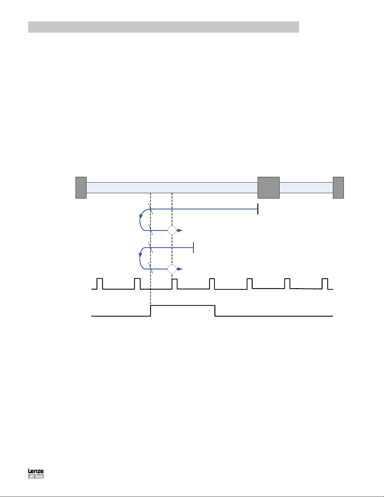
Programming
2.15.9.13 Homing Method 13: Homing on the Home Switch & Index Pulse
Using this method the initial direction of movement is negative. The home position is the first index pulse to the positive
of the position where the homing switch becomes inactive on its positive edge.
Axis will accelerate to fast homing velocity in the negative direction and continue until Homing Switch (selectable via
Var_Home_Switch_Input Variable) is deactivated (falling edge) shown at position A. Axis then decelerates to zero
velocity.
If the homing switch is already active when the homing routine commences then this does not effect this mode of
homing as the procedure is searching for falling edge of homing switch in both cases.
Axis will then accelerate to fast homing velocity in positive direction. Motion will continue until first the rising edge of the
Homing switch is detected (position B) and then the rising edge of the first index pulse (position 13) is detected.
NOTE: if the axis is on the wrong side of the homing switch when homing is started then the axis will move negative until
it contacts the negative limit switch (A1). Upon activating the negative limit switch the axis will change direction (positive)
following the procedure as detailed above but ignoring the initial move in the negative direction.
A
Index Pulse
(via Input C3)
Homing Switch
(Var_Home_Switch_Input)
B
1 3
A
B
1 3
Figure 37: Homing Method 13
PM94P01C 71
Page 74

Programming
2.15.9.14 Homing Method 14: Homing on the Home Switch & Index Pulse
Using this method the initial direction of movement is negative. The home position is the first index pulse to the negative
of the position where the homing switch becomes inactive.
Axis will accelerate to fast homing velocity in the negative direction and continue until Homing Switch (selectable via
Var_Home_Switch_Input Variable) is deactivated (falling edge) shown at position A.
If the homing switch is already active when the homing routine commences then this does not effect this mode of
homing as the procedure is searching for falling edge of homing switch in both cases.
Axis will continue running at fast homing velocity in negative direction until the rising edge of the first index pulse
(position 14) is detected.
NOTE: if the axis is on the wrong side of the homing switch when homing is started then the axis will move negative until
it contacts the negative limit switch (A1). Upon activating the negative limit switch the axis will change direction (positive)
continuing motion until it sees the rising edge of the homing switch. The axis will then stop and follow the procedure as
detailed above.
Index Pulse
(via Input C3)
Homing Switch
(Var_Home_Switch_Input)
1 4
1 4
A
A
Figure 38: Homing Method 14
PM94P01C72
Page 75

Programming
2.15.9.15 Homing Method 17: Homing without an Index Pulse
Method 17 is similar to method 1, except that the home position is not dependent on the index pulse but only on the
negative limit switch translation.
Using this method the initial direction of movement is negative. The home position is the leading edge of the Negative
limit switch.
Axis will accelerate to fast homing velocity in the negative direction and continue until Negative Limit Switch (A1) is
activated (rising edge) shown at position A. Axis then decelerates to zero velocity.
If the negative limit switch is already active when the homing routine commences then this initial move is not
executed.
Axis will then accelerate to fast homing velocity in the positive direction. Motion will continue until the falling edge of the
negative limit switch is detected (position B), where the axis will decelerate to 0 velocity.
Axis will then accelerate to slow homing velocity in the negative direction. Motion will continue until the rising edge of
the negative limit switch is detected (position C), where the axis will decelerate to 0 velocity.
Axis will then accelerate to slow homing velocity divided by 100 in the positive direction. Motion will continue until the
falling edge of the negative limit switch is detected (position 17). This is the home position (excluding offset).
Negative Limit Switch
(Input A1)
A
B
C
1 7
Figure 39: Homing Method 17
PM94P01C 73
Page 76
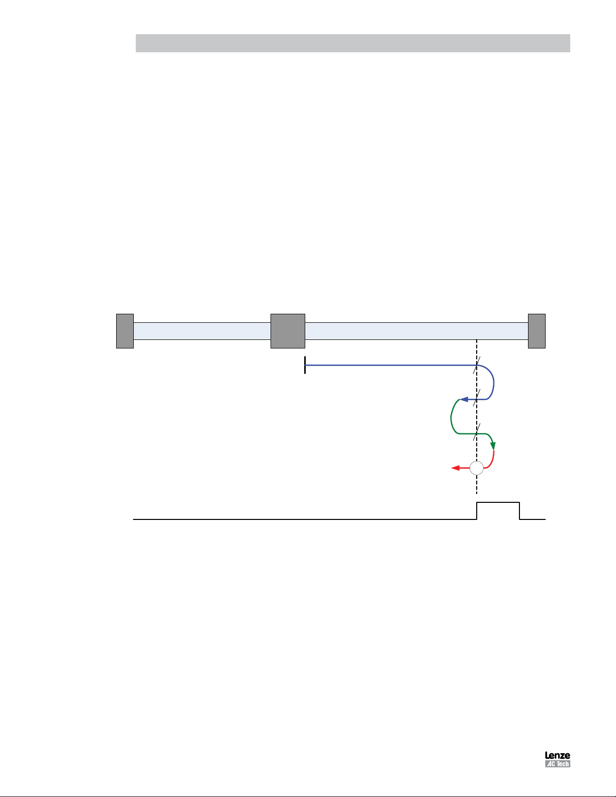
Programming
2.15.9.16 Homing Method 18: Homing without an Index Pulse
Method 18 is similar to method 2, except that the home position is not dependent on the index pulse but only on the
Positive limit switch translation.
Using this method the initial direction of movement is positive. The home position is the leading edge of the Positive
limit switch.
Axis will accelerate to fast homing velocity in the positive direction and continue until Positive Limit Switch (A2) is
activated (rising edge) shown at position A. Axis then decelerates to zero velocity.
If the positive limit switch is already active when the homing routine commences then this initial move is not executed.
Axis will then accelerate to fast homing velocity in the negative direction. Motion will continue until the falling edge of
the positive limit switch is detected (position B), where the axis will decelerate to 0 velocity.
Axis will then accelerate to slow homing velocity in the positive direction. Motion will continue until the rising edge of the
positive limit switch is detected (position C), where the axis will decelerate to 0 velocity.
Axis will then accelerate to slow homing velocity divided by 100 in the negative direction. Motion will continue until the
falling edge of the positive limit switch is detected (position 18). This is the home position (excluding offset).
Positive Limit Switch
(Input A2)
A
B
C
1 8
Figure 40: Homing Method 18
PM94P01C74
Page 77

Programming
2.15.9.17 Homing Method 19: Homing without an Index Pulse
Using this method the initial direction of movement is positive (if the homing switch is inactive). The home position is the
leading edge of the homing switch.
Axis will accelerate to fast homing velocity in the positive direction and continue until the homing switch is activated
(rising edge) shown at position A. Axis then decelerates to zero velocity.
If the homing switch is already active when the homing routine commences then this initial move is not executed.
Axis will then accelerate to fast homing velocity in the negative direction. Motion will continue until the falling edge of
the homing switch is detected (position B), where the axis will decelerate to 0 velocity.
Axis will then accelerate to slow homing velocity in the positive direction. Motion will continue until the rising edge of the
homing switch is detected (position C), where the axis will decelerate to 0 velocity.
Axis will then accelerate to slow homing velocity in the negative direction. Motion will continue until the falling edge of
the homing switch is detected (position 19). This is the home position (excluding offset).
A
Homing Switch
(Var_Home_Switch_Input)
B
C
1 9
Figure 41: Homing Method 19
PM94P01C 75
Page 78

Programming
2.15.9.18 Homing Method 21: Homing without an Index Pulse
Using this method the initial direction of movement is negative (if the homing switch is inactive). The home position is
the leading edge of the homing switch.
Axis will accelerate to fast homing velocity in the negative direction and continue until the homing switch is activated
(rising edge) shown at position A. Axis then decelerates to zero velocity.
If the homing switch is already active when the homing routine commences then this initial move is not executed.
Axis will then accelerate to fast homing velocity in the positive direction. Motion will continue until the falling edge of the
homing switch is detected (position B), where the axis will decelerate to 0 velocity.
Axis will then accelerate to slow homing velocity in the negative direction. Motion will continue until the rising edge of
the homing switch is detected (position C), where the axis will decelerate to 0 velocity.
Axis will then accelerate to slow homing velocity in the positive direction. Motion will continue until the falling edge of
the homing switch is detected (position 21). This is the home position (excluding offset).
A
Homing Switch
(Var_Home_Switch_Input)
B
C
2 1
Figure 42: Homing Method 21
PM94P01C76
Page 79

Programming
2.15.9.19 Homing Method 23: Homing without an Index Pulse
Using this method the initial direction of movement is positive (if the homing switch is inactive). The home position is the
leading edge of the homing switch.
Axis will accelerate to fast homing velocity in the positive direction and continue until the homing switch (selectable via
Var_Home_Switch_Input Variable) is activated (rising edge) shown at position A. Axis then decelerates to zero velocity.
If the homing switch is already active when the homing routine commences then this initial move is not executed.
Axis will then accelerate to fast homing velocity in the negative direction. Motion will continue until the falling edge of
the homing switch is detected (position B), where the axis will decelerate to 0 velocity.
Axis will then accelerate to slow homing velocity in the positive direction. Motion will continue until the rising edge of the
homing switch is detected (position C), where the axis will decelerate to 0 velocity.
Axis will then accelerate to slow homing velocity in the negative direction. Motion will continue until the falling edge of
the homing switch is detected (position 23). This is the home position (excluding offset).
NOTE: if the axis is on the wrong side of the homing switch when homing is started then the axis will move positive until
it contacts the positive limit switch (A2). Upon activating the positive limit switch the axis will change direction (negative)
following the procedure as detailed above but ignoring the initial move in the positive direction.
Homing Switch
(Var_Home_Switch_Input)
A
B
C
2 3
B
C
2 3
Figure 43: Homing Method 23
PM94P01C 77
Page 80

Programming
2.15.9.20 Homing Method 25: Homing without an Index Pulse
Using this method the initial direction of movement is positive. The home position is the negative edge of the homing
switch.
Axis will accelerate to fast homing velocity in the positive direction and continue until Homing Switch (selectable via
Var_Home_Switch_Input Variable) is deactivated (falling edge) shown at position A. Axis then decelerates to zero
velocity.
If the homing switch is already active when the homing routine commences then this does not effect this mode of
homing as the procedure is searching for falling edge of homing switch in both cases.
Axis will then accelerate to slow homing velocity in the negative direction. Motion will continue until the rising edge of
the homing switch is detected (position B), where the axis will decelerate to 0 velocity.
Axis will then accelerate to slow homing velocity in the positive direction. Motion will continue until the falling edge of
the homing switch is detected (position 25). This is the home position (excluding offset).
NOTE: if the axis is on the wrong side of the homing switch when homing is started then the axis will move positive until
it contacts the positive limit switch (A2). Upon activating the positive limit switch the axis will change direction (negative)
continuing motion until it sees the rising edge of the homing switch. The axis will then stop and follow the procedure as
detailed above.
Homing Switch
(Var_Home_Switch_Input)
A
B
2 5
A
B
2 5
Figure 44: Homing Method 25
PM94P01C78
Page 81

Programming
2.15.9.21 Homing Method 27: Homing without an Index Pulse
Using this method the initial direction of movement is negative. The home position is the negative edge of the homing
switch.
Axis will accelerate to fast homing velocity in the negative direction and continue until Homing Switch (selectable via
Var_Home_Switch_Input Variable) is deactivated (falling edge) shown at position A. Axis then decelerates to zero
velocity.
If the homing switch is already active when the homing routine commences then this does not effect this mode of
homing as the procedure is searching for falling edge of homing switch in both cases.
Axis will then accelerate to slow homing velocity in the positive direction. Motion will continue until the rising edge of the
homing switch is detected (position B), where the axis will decelerate to 0 velocity.
Axis will then accelerate to slow homing velocity in the negative direction. Motion will continue until the falling edge of
the homing switch is detected (position 27). This is the home position (excluding offset).
NOTE: if the axis is on the wrong side of the homing switch when homing is started then the axis will move negative until
it contacts the negative limit switch (A1). Upon activating the negative limit switch the axis will change direction (positive)
continuing motion until it sees the rising edge of the homing switch. The axis will then stop and follow the procedure as
detailed above.
Homing Switch
(Var_Home_Switch_Input)
A
B
2 7
A
B
2 7
Figure 45: Homing Method 27
PM94P01C 79
Page 82

Programming
2.15.9.22 Homing Method 29: Homing without an Index Pulse
Using this method the initial direction of movement is negative (if the homing switch is inactive). The home position is
the leading edge of the homing switch.
Axis will accelerate to fast homing velocity in the negative direction and continue until the homing switch (selectable via
Var_Home_Switch_Input Variable) is activated (rising edge) shown at position A. Axis then decelerates to zero velocity.
If the homing switch is already active when the homing routine commences then this initial move is not executed.
Axis will then accelerate to fast homing velocity in the positive direction. Motion will continue until the falling edge of the
homing switch is detected (position B), where the axis will decelerate to 0 velocity.
Axis will then accelerate to slow homing velocity in the negative direction. Motion will continue until the rising edge of
the homing switch is detected (position C), where the axis will decelerate to 0 velocity.
Axis will then accelerate to slow homing velocity in the positive direction. Motion will continue until the falling edge of
the homing switch is detected (position 29). This is the home position (excluding offset).
NOTE: if the axis is on the wrong side of the homing switch when homing is started then the axis will move negative until
it contacts the negative limit switch (A1). Upon activating the negative limit switch the axis will change direction (positive)
following the procedure as detailed above but ignoring the initial move in the negative direction.
Homing Switch
(Var_Home_Switch_Input)
A
B
C
2 9
B
C
2 9
Figure 46: Homing Method 29
PM94P01C80
Page 83
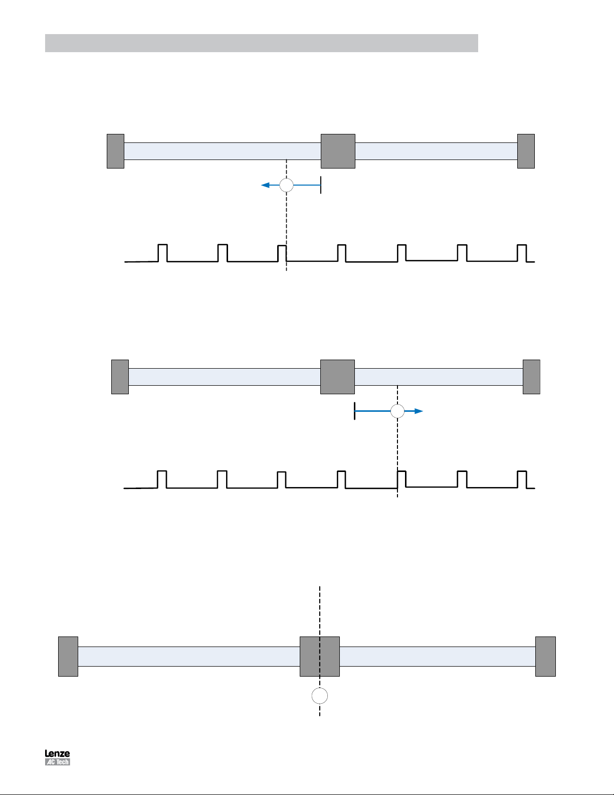
Programming
2.15.9.23 Homing Method 33: Homing to an Index Pulse
Using this method the initial direction of movement is negative. The home position is the first index pulse to the negative
of the shaft starting Position. Axis will accelerate to fast homing velocity in the negative direction and continue until the
rising edge of the first index pulse (position 33) is detected.
3 3
Index Pulse
(via Input C3)
Figure 47: Homing Method 33
2.15.9.24 Homing Method 34: Homing to an Index Pulse
Using this method the initial direction of movement is positive. The home position is the first index pulse to the positive
of the shaft starting Position. Axis will accelerate to fast homing velocity in the positive direction and continue until the
rising edge of the first index pulse (position 34) is detected.
3 4
Index Pulse
(via Input C3)
Figure 48: Homing Method 34
2.15.9.25 Homing Method 35: Using Current Position as Home
Using this method the current position of the axis is taken as the home position. There is no motion of the motor
shaft during this procedure. Any offset specified (via the Var_Home_Offset Variable) will be added to the stored home
position.
3 5
Figure 49: Homing Method 35
PM94P01C 81
Page 84

Programming
2.15.10 Homing Mode Operation example
The following steps are needed to execute the homing operation from the user program or under interface control.
1. Set Fast homing speed: Variable #242
2. Set Slow homing speed: Variable #243
3. Set Homing accel/decel: Variable #239
4. Set home offset:
a. In User Units Variable #240
b. In encoder pulses Variable #241
5. Set Home Switch Input Variable #246
6. Select Home Method Variable #244
‘HOME’ is the logical command to set VAR_START_HOMING. Writing the word ‘HOME’ within the user program will
result in the homing operation commencing. After initiating the HOME command with firmware 3.60 (and later) the user
program will not execute subsequent lines of code until after homing is completed (similar to MOVE P). If either using
firmware prior to 3.60 or if user initiates homing in the indexer program via the statement VAR_START_HOMING=1,
then it is recommended to immediately follow that statement with the following code:
WAIT UNTIL VAR_EXSTATUS & 0x400000 == 0x400000.
Doing this ensures no further lines of code will be executed until homing is complete.
;Program start------------------------------------------------------------------;
;
UNITS=1 ;rps
Accel=1000
Decel=1000
MaxV =20
;some program statements…
;
;
;Homing specific set up..
VAR_HOME_FAST_VEL= 10 ;rps
VAR_HOME_SLOW_VEL= 1 ;rps
VAR_HOME_ACCEL= 100 ;rps/sec^2
VAR_HOME_OFFSET= 0 ;no offset from sensor
VAR_HOME_SWITCH_INPUT= 4 ;input B1 (0-A1, 1-A2…3-A4,4-B1,…11-C4)
VAR_HOME_METHOD= 4 ;see table 22
ENABLE
HOME ;starts homing sequence
WAIT UNTIL VAR_EXSTATUS & 0x400000 == 0x400000 ;wait for homing complete
;Drive homed
;Program statements…
END
PM94P01C82
Page 85

Reference
3. Reference
3.1 Program Statement Glossary
Each statement, system variable or operand is documented using the tabular format shown in Tables 23 and 24. The
field label is still shown even if there is no information for a particular field. The individual program statements are listed
in this section in alphabetical order with detailed descriptions in Tables 25 through 60.
Table 23: Language Format
KEYWORD Long Name Type
Purpose
Syntax
Remarks
See Also
Example
Field Descriptions
KEYWORD:
Description:
Type:
Purpose:
Syntax:
Arguments:
Remarks:
See Also:
Example:
Reference
KEYWORD <ARGUMEMTS> ,[MODIFIERS]
Table 24: Field Descriptions
The KEYWORD is the name of the programming statement as it would appear in a program.
The description is an interpretation of the keyword. For example: MOVEP is the keyword and Move
to Position would be a description. The description is provided only as an aid to the reader and may
not be used in a program.
The type field will identify the Keyword as either a Statement or a Pseudo statement.
Statements are actual instructions converted to machine code by the compiler and form executable
commands within the drive programming.
Pseudo statements add convenience to the programmer but do not form instructions in their own
right. They are therefore not executable code and are effectively removed when the program is
compiled to it’s native state by the compiler.
Purpose or Function of the Keyword (Programming Statement).
This field shows proper usage of the keyword. Arguments will be written in < > brackets. Optional
arguments will be contained within [ ] brackets.
The data that is supplied with a statement that modifies the behavior of the statement. For example,
MOVED=100. MOVED is the statement and 100 is the argument.
The remark field contains additional information about the use of the statement.
This field contains a list of statements that are related to the purpose of the keyword.
The example field contains a code segment that illustrates the usage of the keyword
PM94P01C 83
Page 86

Reference
Table 25: ASSIGN
ASSIGN Assign Input As Index Bit Statement
Purpose
Syntax
Remarks
See Also
Example:
ASSIGN INPUT IN_B1 AS BIT 0 ;index bit 0 state matches state of input B1
ASSIGN INPUT IN_B2 AS BIT 1 ;index bit 1 state matches state of input B2
Program Start:
; <statements>
If Index == 0 ; If neither IN_B1 or IN_B2 is on
MoveP 0 ; Move to Absolute Position 0
Endif
Assign keyword causes a specified input to be assigned to a particular bit of system variable INDEX.
Up to 8 digital inputs can be assigned to the first eight bits (bits 0 - 7) of the INDEX system variable in
any order or combination. The purpose of the Assign Keyword and INDEX system Variable is to allow
the creation of a custom input word for inclusion in the user program. Good examples of it’s use are
for implementing easy selection of preset torque, velocity or position values within the user program.
ASSIGN INPUT <input name> AS BIT <bit #>
Input name (IN_A1..IN_A2 etc.)
Bit# INDEX variable bit number from 0 to 7
Assign statements typically appear at the start of the program (Initialize and set Variables section) but
can be included in other code sections with the exception of Events and the Fault Handler.
VAR_IOINDEX Variable (#220)
If Index == 1 ; If IN_B1 is on and IN_B2 is off
MoveP 10 ; Move to Absolute Position 10
Endif
; If Index == 2 .....
PM94P01C84
Page 87

Reference
Table 26: DEFINE
DEFINE Define name Pseudo-statement
Purpose
Syntax
Remarks:
See Also
Example:
Define Start_Button IN_B1 ; Define a Digital Input
Define System_Stop Out2 ; Define a Digital Output
Define Loop_Counter V5 ; Define a User Variable
Define Loop_Increment 1 ; Define a Constant Value
Program_Start: ; Label Program Start
If Start_Button == 0 ; If input B1 is off
Disable ; Disable Servo
System_Stop = 1 ; Turn on Output 2
Else ; Otherwise
System_Stop = 0 ; Turn off Output 2
Enable ; Enable Servo
MoveD 10 ; Move (increment) Distance
10
Loop_Counter = Loop_Counter + Loop_Increment ; Increment Variable V5 by 1
Endif
Goto Program_Start ; Goto Label Program_Start
DEFINE is used to define symbolic names for User Variables, constants, and Digital I/O for
programming convenience. Define statements greatly enhance program understanding by allowing
the user to program using symbolic strings (names)relevant to their application. DEFINE can be used
also to substitute a symbolic string.
DEFINE <name> <string>
name any symbolic string
string User Variable, constant, or Digital I/O Flag that symbolic string will represent
DEFINE statements can be located anywhere within the user program (with the exception of events
and the fault handler). Normally practice however is to place definitions at the start of the program
prior to any executable code.
Table 27: DISABLE
DISABLE Disables the drive Statement
Purpose
Syntax
Remarks
See Also
Example:
DISABLE turns OFF the power to the motor. Drive shows ‘Dis’ on display when in a disabled state.
DISABLE
Once the DISABLE statement is executed, the power to the motor is turned off and the motor can
move freely. When disabled the drive will continue to monitor feedback and the actual position
variable (APOS) will continue to update with the current position of the motor. The target position
variable (TPOS) will be updated with the value of the actual position variable (APOS) on Enable to
prevent unexpected motion from the motor shaft.
ENABLE
If Start_Button == 0 ; If input B1 is off
Disable ; Disable Servo
Else ; Otherwise
Enable ; Enable Servo
MoveD 10 ; Move (increment) Distance 10
Endif
PM94P01C 85
Page 88

Reference
Table 28: DO UNTIL
DO UNTIL Do/Until Statement
Purpose
Syntax
Remarks
See Also
Example:
V0 = 0 ; Set V0 to Value 0
; Create Loop to perform Move command 12 times
DO ; Start of Do Loop
V0 = V0 + 1 ; Add 1 to Variable V0
Moved 5 ; Move (incremental) distance 5
Until V0 == 12 ; Loop back to DO Statement, Repeat Until Logic True
The DO / UNTIL statement is used to execute a statement or set of statements repeatedly until a
logical condition becomes true. The Do / Until statements enclose the program code to be repeatedly
executed with the UNTIL statement containing the logical statement for exit of the loop.
DO
{statement(s)}…
UNTIL <condition>
{statement(s)} any valid statement(s)
<condition> The condition to be tested.
The loop statement or statements contained within a DO / UNTIL loop will always be executed at least
once because the logical condition to be tested is contained within the UNTIL statement in the last
statement of the loop.
WHILE, IF
Table 29: ENABLE
ENABLE Enables the drive Statement
Purpose
Syntax
Remarks
See Also
Example:
Enable turns on power to the motor. Drive shows ‘Run’ on display when in the enabled state.
ENABLE
Once a drive is enabled motion can be commanded from the user program. Commanding motion
while the drive is disabled will result in fault trip (F_27).
DISABLE
If Start_Button == 0 ; If input B1 is off
Disable ; Disable Servo
Else ; Otherwise
Enable ; Enable Servo
MoveD 10 ; Move (increment) Distance 10
Endif
Table 30: END
END END program Statement
Purpose
Syntax
Remarks
See Also
Example:
This statement is used to terminate (finish) user program and its events.
END
END can be used anywhere in program
DISABLE
END ;end user program
PM94P01C86
Page 89

Reference
Table 31: EVENT
EVENT Starts Event handler Statement
Purpose
Syntax
Remarks
For syntax 1 and 2:
The Event will occur when the input with the <name/number> transition from L(Low) to H (High), for syntax 1 (RISE) and
from H (High) to L(Low) for syntax 2 (FALL).
For syntax 3:
The Event will occur when the specified , <period>, period of time has expired. This event can be used as periodic event to
check for some conditions.
For syntax 4
The Event will occur when the expression, <expression>, evaluates to be true. The expression can be any valid arithmetic
or logical expression or combination of the two. This event can be used when implementing soft limit switches or when
changing the program flow based on some conditions. Any variable, (user and system), or constants can be used in the
expression. The event will only trigger when the logic transitions from False to True. Further occurrence of the event will not
occur while the condition remains true.
See Also
Example:
EVENT InEvent IN_A1 RISE
V0 = V0+1 ;V0 increments by 1 each time IN_A1 transitions from low to high
ENDEVENT
EVENT period TIME 1000 ;1000 ms = 1Sec
V3=V0-V1 ;Event subtracts V1 from V0 and stores result in V3 every second (1000mS)
ENDEVENT
;----------------------------------------------------------------------------- EVENT InEvent ON
EVENT period ON
{program statements}
END
EVENT keyword is used to create scanned events within the user program.
Statement also sets one of 4 possible types of events.
Any one of the 4 syntax examples herein may be used:
1. EVENT <name> INPUT <inputname> RISE
2. EVENT <name> INPUT <inputname> FALL
3. EVENT <name> TIME <period>
4. EVENT <name> <expression>
name any valid alphanumeric string
inputname any valid input “IN_A1 - IN_C4”
period any integer number. Expressed in ms
expression any arithmetic or logical expression
The following statements can not be used within event’s handler:
MOVE,MOVED,MOVEP,MOVEDR,MOVEPR,MDV
MOTION SUSPEND
MOTION RESUME
STOP MOTION
DO UNTIL
GOTO
GOSUB
HALT
VELOCITY ON/OFF
WAIT
WHILE
While GOTO or GOSUB are restricted, a special JUMP statement can be used for program flow change from
within event handler. See JUMP statement description in Language Reference section.
ENDEVENT, EVENT ON, EVENT OFF
PM94P01C 87
Page 90

Reference
Table 32: ENDEVENT
ENDEVENT END of Event handler Statement
Purpose
Syntax
Remarks
See Also
Example:
EVENT ON/OFF Turn events on or off Statement
Purpose
Syntax
Remarks
See Also
Example:
EVENT InputRise ON
EVENT InputRise OFF
Indicates end of the scanned event code
ENDEVENT
EVENT, EVENT ON, EVENT OFF
EVENT InputRise IN_B4 RISE
V0=V0+1
ENDEVENT
Table 33: EVENT ON/OFF
Turns ON or OFF events created by an EVENT handler statement
EVENT <name> ON
EVENT <name> OFF
<name> Event handler name
EVENT
PM94P01C88
Page 91

Reference
Table 34: EVENTS ON/OFF
EVENTS OFF/ON Globally Disables/enables events Statement
Purpose
Syntax
Remarks
See Also
Example:
********************************************************************************
EVENT SKIPOUT IN_B4 RISE ;check for rising edge of input B4
JUMP TOGGLE ;redirect code execution to TOGGLE
ENDEVENT ;end the event
EVENT OVERSHOOT IN_B3 RISE ;check for rising edge of input B3
JUMP SHUTDOWN ;redirect code execution to SHUTDOWN
ENDEVENT ;end the event
********************************************************************************
EVENT SKIPOUT ON
EVENT OVERSHOOOT ON
********************************************************************************
……….…User code……………..
EVENTS OFF ;turns off all events
EVENTS OFF command when executed will disable any events currently enabled (running). EVENTS
ON Command re-enables any events previously disabled through the events off command. EVENTS
ON is not a global enable of all declared events. Events status is indicated through bit #30 of the
DSTATUS register or by system flag ‘F_EVENTSOFF’. EVENTS OFF/ON allows for easy disable and
re-activation of events in sections of the main program or subroutines that the programmer doesn’t
want interrupted by event code.
EVENTS OFF Disables execution of all events
EVENTS ON Restores execution of previously enabled events.
Events are globally disabled after a reset is made. Events are re-enable by executing the individual
EVENT <name> ON statement.
EVENT
……….…User code……………..
EVENTS ON ;turns on any event previously activated
Table 35: FAULT
FAULT User generated fault Statement
Purpose
Syntax
Remarks
See Also
Example:
Allows the user program to set a custom system fault. This is useful when the programmer needs to
define a fault code and fault process for custom conditions like data supplied by interface out of range
etc. Custom fault numbers must be in region of 128 to 240 (decimal)
FAULT FaultNumber Sets system fault.
Faultnumber - constant in range 128-240
Variables are not allowed in this statement.
Custom fault will be processed as any regular fault. There will be a record in the fault log.
ON FAULT
FAULT 200 ;Sets fault #200
V0=200
FAULT V0 ;Not valid. Variables are not allowed here
PM94P01C 89
Page 92

Reference
Table 36: GOSUB
GOSUB Go To subroutine Statement
Purpose
Syntax
Remarks
See Also
Example:
DO
GOSUB CALCMOVE ;Go to CALCMOVE Subroutine
MOVED V1 ;Move distance calculated in Subroutine
UNTIL INA1
END
SUB CALCMOVE:
V1=(V2+V3)/2 ;Subroutine statement, Calculates value for V1
RETURN ;Return to main program execution
GOSUB transfers control to subroutine.
GOSUB <subname>
<subname> a valid subroutine name
After return from subroutine program resumes from next statement after GOSUB
GOTO, JUMP, RETURN
Table 37: GOTO
GOTO Go To Statement
Purpose
Syntax
Remarks
See Also
Example:
Transfer program execution to label following the GOTO instruction.
GOTO <label>
GOSUB, JUMP
GOTO Label2
{Statements…}
Label2:
{Statements…}
Table 38: HALT
HALT Halt the program execution Statement
Purpose
Syntax
Remarks
See Also
Example:
Used to halt main program execution. Events are not halted by the HALT statement. Execution will be
resumed by the RESET statement or by executing a JUMP to code from the EVENT handler.
HALT
This statement is convenient when writing event driven programs.
RESET
{Statements…}
HALT ;halt main program execution and wait for event
PM94P01C90
Page 93

Reference
Table 39: HOME
HOME Execute homing routine Statement
Purpose
Syntax
Remarks
See Also
Example:
{Statements…}
HOME ;initiate homing routine
ICONTROL
ON/OFF Enables interface control Statement
Purpose
Syntax
Remarks
See Also
Example:
EVENT LimitSwitch IN_A1 RISE ;limit switch event
Jump LimitSwitchHandler ;jump to process limit switch
ENDEVENT
V0=0 ;V0 will be used to indicate fault condition
EVENT LimitSwitch ON ;Turn on event to detect limit switch activation
Again:
HALT ;system controlled by interface
LimitSwitchHandler:
EVENTS OFF ;turn off all events
ICONTROL OFF ;disable interface control
STOP MOTION QUICK
DISABLE ;DISABLE
V0=1 ;indicate fault condition to the interface
ICONTROL ON ;Enable Interface Control
EVENTS ON ;turn on events turned off by ‘EVENTS OFF’
GOTO AGAIN
Used to initiate homing.
HOME
This statement is convenient when writing event driven programs.
Table 40: ICONTROL ON/OFF
Enables/Disables interface control. Effects bit #27 in DSTATUS register and system flag F_ICONTROLOFF.
All interface motion commands and commands changing any outputs will be disabled. See Host interface
commands manual for details. This command is useful when the program is processing critical states
(example limit switches) and can’t be disturbed by the interface.
ICONTROL ON
ICONTROL OFF
After reset interface control is enabled by default.
Enables Interface control
Disables interface control
PM94P01C 91
Page 94

Reference
Table 41: IF
IF IF/ENDIF Statement
Purpose
Syntax
Remarks
See Also
Example:
IF APOS > 4 ;If actual position is greater than 4 units
V0=2
ELSE ;otherwise... (actual position equal or less than 4)
V0=0
ENDIF
;----------------------------------------------------------
If V1 <> V2 && V3>V4 ;If V1 doesn’t equal V2 AND V3 if greater than V4
V2=9
ENDIF
The IF statement tests for a condition and then executes the specific action(s) between the IF and
ENDIF statements if the condition is found to be true. If the condition is false, no action is taken and
the instructions following the ENDIF statement are executed. Optionally, using the ELSE statement, a
second series of statements may be specified to be executed if the condition is false.
IF <condition>
{statements 1}
ELSE
{statements 2}
ENDIF
WHILE, DO
Table 42: JUMP
JUMP Jump to label from Event handler Statement
Purpose
Syntax
Remarks
See Also
Example:
This is a special purpose statement to be used only in the Event Handler code. When the EVENT is
triggered and this statement is processed, execution of the main program is transferred to the <label>
argument called out in the “JUMP” statement. The Jump statement is useful when there is a need for
the program’s flow to change based on some event(s). Transfer program execution to the instruction
following the label.
JUMP <label>
<label> is any valid program label
Can be used in EVENT handler only.
EVENT
EVENT ExternalFault INPUT IN_A4 RISE ;activate Event when IN_A4 goes high
JUMP ExecuteStop ;redirect program to <ExecuteStop>
ENDEVENT
StartMotion:
EVENT ExternalFault ON
ENABLE
MOVED 20
MOVED -100
{statements}
END
ExecuteStop:
STOP MOTION ;Motion stopped here
DISABLE ;drive disabled
Wait Until !IN_A4 ;Wait Until Input A4 goes low
GOTO StartMotion
PM94P01C92
Page 95

Reference
Table 43: MDV
MDV Segment Move Statement
Purpose
Syntax
See Also
Example:
{Statements…}
MDV 5, 10 ;Move 5 user units and accelerate to a velocity of 10
MDV 10,10 ;Move 10 user units and maintain a velocity of 10
MDV 10,5 ;Move 10 user units and decelerate to velocity of 5
MDV 5,;0 ;Move 5 user units and decelerate to velocity 0.
;The last MDV must have a final velocity of 0.
{Statements…}
MDV defines individual motion segment by specifying distance and final velocity (for each segment) in
User Units. Acceleration (or deceleration) is calculated automatically based on these two parameters.
This technique allows complicated moves to be created that consist of many segments. Each MDV
sequence (series of MDV segments) starts and ends with a velocity of 0. Based on this an MDV
sequence must have at least two segments. The MDV statement doesn’t suspend execution of
the main program. Each segment is loaded into the Motion Queue and the sequence executed
immediately. If the last segment in the Motion Queue doesn’t have a final velocity of 0, the drive will
generate a “Motion Queue Empty” fault #24. If the “S” modifier is used in the statement, then the
velocity acceleration/deceleration will be S-curved as opposed to be linear.
MDV <[-]segment distance>,<segment final velocity> [,S]
S[-curve] optional modifier specifies S-curve acceleration / deceleration.
MOVE, MOVEP, MOVEPR, MOVED, MOVEDR, MOTION SUSPEND, MOTION RESUME
Table 44: MEMGET
MEMGET Memory access statements MEMGET Statement
Purpose
Syntax
MEMGET provides command for simplified retrieval of data from the drives RAM memory file through
transfer of data to the variables V0-V31. Using this statement any combinations of variables V0-V31
can be retrieved from the RAM file with a single statement.
MEMGET <offset> [ <varlist>]
<offset> It specifies offset in RAM file where data will be retrieved.
Range: -32767 to 32767
<varlist> any combinations of variables V0-V31
See Also
Example:
MEMSET
MEMGET 5 [V0] ;single variable will be retrieved from location 5
MEMGET V1 [V0,V3,V2] ;variables V0,V3,V2 will be retrieved from
;memory location starting at value held in V1
MEMGET 10 [V3-V7] ;variables V3 to V7 inclusively will be retrieved
MEMGET V1 [V0,V2,V4-V8] ;variables V0,V2, V4 through V8 will be retrieved
PM94P01C 93
Page 96

Reference
Table 45: MEMSET
MEMSET Memory access statements MEMSET Statement
Purpose
Syntax
See Also
Example:
MEMSET 5 [V0] ;single variable will be stored in location 5
MEMSET V1 [V0,V3,V2] ;variables V0,V3,V2 will be stored in memory
;location starting at value held in V1
MEMSET 10 [V3-V7] ;variables V3 to V7 inclusively will be stored
MEMSET V1 [V0,V2,V4-V8] ;variables V0,V2, V4 through V8 will be stored.
MEMSET provides command for simplified storage of data to the drives RAM memory file through
transfer of data from variables V0-V31. Using this statement any combinations of variables V0-V31
can be stored in the RAM file with a single statement.
MEMSET <offset> [ <varlist>]
<offset> It specifies offset in RAM file where data will be stored.
Range: -32767 to 32767
<varlist> any combinations of variables V0-V31
MEMGET
Table 46: MOTION RESUME
MOTION RESUME Resume Motion Statement
Purpose
Syntax
See Also
Example:
Statement resumes motion previously suspended by MOTION SUSPEND. If motion was not
previously suspended, this has no effect on operation.
MOTION RESUME
MOVE, MOVEP, MOVEDR, MOVED, MOVEPR ,MDV, MOTION SUSPEND
…{statements}
MOTION RESUME ;Motion is resumed from first command in motion Queue (if any)
…{statements}
Table 47: MOTION SUSPEND
MOTION SUSPEND Suspend Statement
Purpose
Syntax
Remarks
See Also
Example:
This statement is used to temporarily suspend motion without flushing the Motion Queue’s contents.
If this statement is executed while a motion profile is being processed, then the motion will not be
suspended until after the completion of the move. If executing a series of segment moves, motion
will not be suspended until after all the MDV segments have been processed. If the Motion Queue is
empty then any subsequent motion statement will be loaded into the queue and will remain there until
the “Motion Resume” statement is executed. Any motion statements without the “C” modifier (except
MDV statements) will lock-up the User Program.
MOTION SUSPEND
Performing any MOVEx commands without “C” modifier will lock-up the user program. You will be
able to unlock it only by performing a Reset or Host Interface command “Motion Resume”
MOVE, MOVEP, MOVEDR, MOVED, MOVEPR ,MDV, MOTION RESUME
…{statements}
MOTION SUSPEND ;Motion will be suspended after current motion
;command is finished.
…{statements}
PM94P01C94
Page 97

Reference
Table 48: MOVE
MOVE Move Statement
Purpose
Syntax
Remarks
See Also
Example:
{Statements…}
MOVE UNTIL V0<3 ;Move until V0 is less than 3
MOVE BACK UNTIL V0>4 ;Move back until V0 is greater than 4
MOVE WHILE V0<3 ;Move While V0 is less than 3
MOVE BACK WHILE V0>4 ;Move While V0 is greater than 4
MOVE WHILE V0<3,C ;Move While V0 < 3, continue program execution
MOVE UNTIL performs motion until condition becomes TRUE. MOVE WHILE performs motion while
conditions stays TRUE. The statement suspends the programs execution until the motion is completed,
unless the statement is used with C modifier.
MOVE [BACK] UNTIL <condition> [,C]
MOVE [BACK] WHILE <condition> [,C]
BACK Changes direction of the move.
C (optional) C[ontinue] - modifier allows the program to continue while motion is being performed.
If a second motion profile is executed while the first profile is still in motion, the second
profile will be loaded into the Motion Stack. The Motion Stack is 32 entries deep. The
programmer should check the “F_MQUEUE_FULL” system flag to make sure that there
is available space in the queue. If the queue becomes full, or overflows, then the drive
will generate a fault.
<condition>
MOVEP, MOVED, MOVEPR, MOVEDR, MDV, MOTION SUSPEND, MOTION RESUME
The condition to be tested. The condition may be a comparison, an input being TRUE or
FALSE (H or L) system flag or a variable is used as flag (if 0 - false, else - true ).
Table 49: MOVED
MOVED Move Distance Statement
Purpose
Syntax
See Also
Example:
MOVED performs incremental motion (distance) specified in User Units. The commanded distance
can range from -231 to 231. This statement will suspend the programs execution until the motion is
completed, unless the statement is used with the “C” modifier. If the “S” modifier is used then S-curve
accel is performed during the move.
MOVED <distance>[,S] [,C]
C[ontinue] The “C” argument is an optional modifier which allows the program to continue executing
while the motion profile is being executed. If the drive is in the process of executing a
previous motion profile the new motion profile will be loaded into the Motion Stack. The
Motion Stack is 32 entries deep. The programmer should check the “F_MQUEUE_FULL”
system flag to make sure that there is available space in the queue. If the queue becomes
full, or overflows, then the drive will generate a fault.
S[-curve] optional modifier specifies S-curve acceleration/deceleration.
MOVE, MOVEP, MOVEPR, MOVEDR, MDV, MOTION SUSPEND, MOTION RESUME
{Statements…}
MOVED 3 ;moves 3 user units forward
MOVED BACK 3 ;moves 3 user units backward
{Statements…}
PM94P01C 95
Page 98

Reference
Table 50: MOVEDR
MOVEDR Registered Distance Move Statement
Purpose
Syntax
See Also
Example:
{Statements…}
MOVEDR 3, 2
{Statements…}
MOVEDR performs incremental motion, specified in User Units. If during the move the registration
input becomes activated (goes high) then the current position is recorded, and the displacement
value (the second argument in the MOVEDR statement) is added to this position to form a new target
position. The end of the move is then altered to this new target position. This statement suspends
execution of the program until the move is completed, unless the statement is used with the “C”
modifier.
MOVEDR <distance>,<displacement> [,S] [,C]
C[ontinue] The “C” argument is an optional modifier which allows the program to continue
executing the User Program while a motion profile is being processed. If a new motion
profile is requested while the drive is processing a move the new motion profile will be
loaded into the Motion Stack. The Motion Stack is 32 entries deep. The programmer
should check the “F_MQUEUE_FULL” system flag to make sure that there is available
space in the queue. If the queue becomes full, or overflows, then the drive will generate
a fault.
S[-curve] optional modifier specifies S-curve acceleration/deceleration.
MOVE, MOVEP, MOVEPR, MOVED, MDV, MOTION SUSPEND, MOTION RESUME
This example moves the motor 3 user units and checks for the registration input.
If registration isn’t detected then the move is completed.
If registration is detected, the registration position is recorded and a displacement value
of 2 is added to the recorded registration position to calculate the new end position.
Table 51: MOVEP
MOVEP Move to Position Statement
Purpose
Syntax
See Also
Example:
MOVEP performs motion to a specified absolute position in User Units. The command range for an
Absolute move is from -2
until the motion is completed unless the statement is used with the “C” modifier. If the “S” modifier is
used then an S-curve accel is performed during the move.
MOVEP <absolute position>[,S] [,C]
C[ontinue] The “C” argument is an optional modifier which allows the program to continue
executing while the motion profile is being executed. If the drive is in the process of
executing a previous motion profile the new motion profile will be loaded into the Motion
Stack. The Motion Stack is 32 entries deep. The programmer should check the “F_
MQUEUE_FULL” system flag to make sure that there is available space in the queue. If
the queue becomes full, or overflows, then the drive will generate a fault.
S[-curve] optional modifier specifies S-curve acceleration/deceleration.
MOVE, MOVED, MOVEPR, MOVEDR, MDV, MOTION SUSPEND, MOTION RESUME
31
to 231 User Units. This statement will suspend the program’s execution
{Statements…}
MOVEP 3 ;moves to 3 user units absolute position
{Statements…}
PM94P01C96
Page 99

Reference
Table 52: MOVEPR
MOVEPR Registered Distance Move Statement
Purpose
Syntax
See Also
Example:
{Statements…}
MOVEPR 3, 2
{Statements…}
MOVEPR performs absolute position moves specified in User Units. If during a move the registration
input becomes activated, i.e., goes high, then the end position of the move is altered to a new target
position. The new position is generated from the second argument in the MOVEPR statement,
(displacement). This statement suspends the execution of the program until the move is completed,
unless the statement is used with the C modifier.
MOVEPR <distance>,<displacement> [,S] [,C]
C[ontinue] The “C” argument is an optional modifier which allows the program to continue
executing the User Program while a motion profile is being processed. If a new motion
profile is requested while the drive is processing a move the new motion profile will be
loaded into the Motion Stack. The Motion Stack is 32 entries deep. The programmer
should check the “F_MQUEUE_FULL” system flag to make sure that there is available
space in the queue. If the queue becomes full, or overflows, then the drive will generate
a fault.
S[-curve] optional modifier specifies S-curve acceleration/deceleration.
MOVE, MOVEP, MOVEDR, MOVED, MDV, MOTION SUSPEND, MOTION RESUME
This example moves the motor to the absolute position of 3 user units while checking for
the registration input.
If registration isn’t detected, then the move is completed .
If registration is detected, the registration position is recorded and a displacement value
of 2 is added to the recorded registration position to calculate the new end position.
PM94P01C 97
Page 100

Reference
Table 53: ON FAULT/ENDFAULT
ON FAULT/
ENDFAULT Defines Fault Handler Statement
Purpose
Syntax
See Also
Example:
…{statements} ;User program
FaultRecovery: ;Recovery procedure
This statement initiates the Fault Handler section of the User Program. The Fault Handler is a piece
of code which is executed when a fault occurs in the drive. The Fault Handler program must begin
with the “ON FAULT” statement and end with the “ENDFAULT” statement. If a Fault Handler routine
is not defined, then the User Program will be terminated and the drive disabled upon the drive
detecting a fault. Subsequently, if a Fault Handler is defined and a fault is detected, the drive will be
disabled, all scanned events will be disabled, and the Fault Handler routine will be executed. The
RESUME statement can be used to redirect the program execution from the Fault Handler back to the
main program. If this statement is not utilized then the program will terminate once the ENDFAULT
statement is executed.
The following statements can’t be used in fault handler:
MOVE, MOVED, MOVEP,MOVEDR, MOVEPR, MDV, MOTION SUSPEND, MOTION RESUME,
GOTO, GOSUB, JUMP, ENABLE, WAIT and VELOCITY ON/OFF
ON FAULT
{…statements}
ENDFAULT
RESUME
…{statements}
END
ON FAULT ;Once fault occurs program is directed here
…{statements} ;Any code to deal with fault
RESUME FaultRecovery ;Execution of RESUME ends Fault Handler and directs
;execution back to User Program.
ENDFAULT ;If RESUME is omitted the program will terminate here
Fault routine must end with a ENDFAULT statement
Table 54: REGISTRATION ON
REGISTRATION ON Registration On Statement
Purpose
Syntax
See Also
Example:
This statement arms the registration input, (input IN_C3). When the registration input is activated,
the Flag Variable “F_REGISTRATION” is set and the current position is captured and stored
to the “RPOS” System Variable. Both of these variables are available to the User Program for
decision making purposes. The “REGISTRATION ON” statement, when executed will reset the “F_
REGISTRATION” flag ready for detection of the next registration input.
REGISTRATION ON Flag “F_REGISTRATION” is reset and
registration input is armed
MOVEDR, MOVEPR
; Moves until input is activated and then come back to the sensor position.
…{statements}
REGISTRATION ON ;Arm registration input
MOVE UNTIL F_REGISTRATION ;Move until input is activated, (sensor hit)
MOVEP RPOS ;Absolute move to the position of the sensor
…{statements}
PM94P01C98
 Loading...