

Page 1

EDKRBM220W
Show/Hide Bookmarks
00468360
Modulwiderstände
8200 motec
10/03
Diese Anleitung
enthält die wesentlichen Technischen Daten und beschreibt die Installation der Modulwiderstände.
ist nur gültig
- für ERBM470R110W und ERBM240R220W
- zusammen mit der Betriebsanleitung des Grundgerätes.
Lesen Sie die Dokumentation zum Grundgerät und beachten Sie die
dortigen Sicherheitshinweise, bevor Sie mit den Arbeiten beginnen.
Einsatzbereich
Die Modulwiderstände mit Leistungen von 110 W und 220 W werden als Lastwiderstände an einem
Frequenzumrichter 8200 motec eingesetzt.
Die Oberflächentemperatur kann bei Nennbelastung ca. 150 °C erreichen!
l
Lenze Drive Systems GmbH, Postfach 10 13 52, D-31763 Hameln
( +49 (0) 5154 82-0, Fax Service: +49 (0) 5154 82-1112
EDKRBM220W
2.0
Page 2

Installation
Show/Hide Bookmarks
Mechanische Installation
Widerstände mit untenliegender Zuleitung montieren
Einbaufreiraum um die Modulwiderstände unbedingt einhalten (siehe Skizze; alle Maße in [mm])
Elektrische Installation
Bremswiderstand an Klemmen BR1 und BR2 des motec anschließen. Dazu die Brücke von BR1 nach
BR0 entfernen.
Leitung 3 und 4 (Temperaturüberwachung) in die Selbsthaltung des jeweiligen Netzschützes der
Versorgung einbinden.
Maximale Belastbarkeit des Temperaturschalters (Öffner):
250 VAC / 0,5 A
Schaltungsbeispiele siehe Dokumentation des motec.
Anschlußleitung
- Länge 2 m
-5x1,5mm
Anschlußbelegung
- 1, 2 = Widerstand
- 3, 4 = Temperaturschalter
-ye/gr=PE
2
(AWG 15)
l
-2-
EDKRBM220W
2.0
Page 3
Installation
Show/Hide Bookmarks
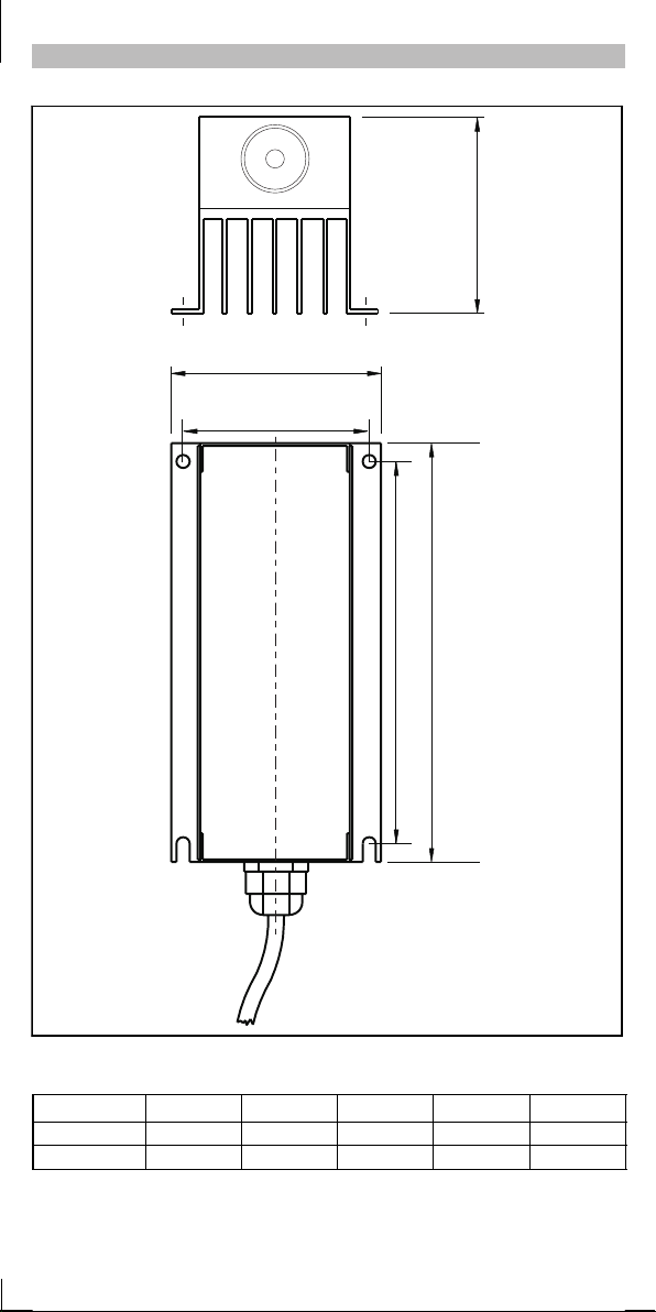
a
a1
b1
e
b
Abmessungen [mm]
Typ a
ERBM470R110W 80 70 160 145 75
ERBM240R220W 80 70 340 325 75
l
a1 b b1 e
-3-
EDKRBM220W
2.0
Page 4

Technische Daten
Typ
Show/Hide Bookmarks
R Leistung max. Spannung Masse
Typ Dauer Spitze (15 s)
[W
W] [W] [kW] [V
WW
ERBM470R110W 470 110 1,3 780 1,4
ERBM240R220W 240 220 2,5 780 2,3
] [kg]
DC
l
-4-
EDKRBM220W
2.0
Page 5

EDKRBM220W
Show/Hide Bookmarks
00468360
Module resistors
8200 motec
10/03
These Instructions
contain the important Technical Data and describe the installation of the module resistors.
are only valid
- for ERBM470R110W and ERBM240R220W
- together with the Operating Instructions of the basic device.
Please read the document ation acc omp anying the b asic device and
observe the safety notes listed before beginning your work.
Range of application
Module resistors with powers of 110 W and 220 W are used as load resistors on a 8200 motec frequency
inverter.
With rated load the surfac e temperat ure may reach ap prox. 150 °C!
l
Lenze Drive Systems GmbH, Postfach 10 13 52, D-31763 Hameln
( +49 (0) 5154 82-0, Fax Service: +49 (0) 5154 82-1112
EDKRBM220W
2.0
Page 6

Installation
Show/Hide Bookmarks
Mechanical Installation
Install resistors vertically with the feeder cable at the bottom
Ensure a free space around the module resistor (see sketch; all dimensions in [mm])
Electrical Installation
Connect brake resistor to the terminals of the motec BR1 and BR2. For this, remove the bridge from
BR1 to BR0.
Interconnect cable 3 and 4 (temperature surveillance) into the locking of the correspondingmains
contactor of the supply.
Maximum capacity of the temperature switch (normally-closed contact):
250 VAC / 0.5 A
For possible connections see documentation of the motec.
Connecting cable
- Length 2 m
-5x1.5mm
Terminal assignment
-1,2=Resistor
- 3, 4 = Temperature switch
-ye/gr=PE
2
(AWG 15)
l
-2-
EDKRBM220W
2.0
Page 7

Installation
Show/Hide Bookmarks
a
a1
b1
e
b
Dimensions [mm]
Typ e a
ERBM470R110W 80 70 160 145 75
ERBM240R220W 80 70 340 325 75
l
a1 b b1 e
-3-
EDKRBM220W
2.0
Page 8

Technical data
Typ
e
Show/Hide Bookmarks
R Power Max. Voltage Mass
Typ e permanent peak (15 s)
[W
W] [W] [kW] [V
WW
ERBM470R110W 470 110 1.3 780 1.4
ERBM240R220W 240 220 2.5 780 2.3
] [kg]
DC
l
-4-
EDKRBM220W
2.0
Page 9

EDKRBM220W
Show/Hide Bookmarks
00468360
Modules de résistance
8200 motec
10/03
Le présent document
contient les principales caractéristiques des modules de résistance et décrit leur installation.
n’est valable que
- pour ERBM470R110W et ERBM240R220W ;
- conjointement avec les instructions de montage de l’appareil de base.
Lire la documentation de l’appareil de base et respecter les consignes de
sécurité comprises d ans la d oc umentation avant t out e act ion.
Domaine d’utilisation
Offrant des puissances de 110 W et 220 W,les modules de résistance sont utilisés comme résistances de
freinage sur le convertisseur de fréquence 8200 motec.
A charge nominale, la t emp érature de surface peut atteindre env. 150 °C!
l
Lenze Drive Systems GmbH, Postfach 10 13 52, D-31763 Hameln
( +49 (0) 5154 82-0, Fax Service: +49 (0) 5154 82-1112
EDKRBM220W
2.0
Page 10

Installation
Show/Hide Bookmarks
Installation mécanique
Monter les résistances avec sortie câble positionnée ver s le bas.
Respecter impérativement un espace libre de montage autours des résistances (voir croquis ; cotes
en [mm])
Installation électrique
Raccorder la résistance de freinage aux bornes BR1 et BR2 du motec. Pour ce faire, enlever le pont
reliant BR1 et BR0.
Relier le câble 3 et 4 (surveillance de température) dans l’auto-maintien de chaque contacteur
réseau.
Charge maxi du contact thermique (contact à ouverture) :
250 VCA / 0,5 A
Exemple de câblage voir documentation du motec.
Câble de raccordement
- Longueur 2 m
-5x1,5mm
Affectation des bornes
-1,2=résistance
- 3, 4 = contact thermique
-ye/gr=PE
2
(AWG 15)
l
-2-
EDKRBM220W
2.0
Page 11

Installation
Show/Hide Bookmarks
a
a1
b1
e
b
Encombrements [mm]
Typ e a
ERBM470R110W 80 70 160 145 75
ERBM240R220W 80 70 340 325 75
l
a1 b b1 e
-3-
EDKRBM220W
2.0
Page 12

Spécifications techniques
Typ
e
Show/Hide Bookmarks
R Puissance Tens ion ma xi Poids
Typ e permanente crête (15 s)
[W
W] [W] [kW] [V
WW
ERBM470R110W 470 110 1,3 780 1,4
ERBM240R220W 240 220 2,5 780 2,3
] [kg]
DC
l
-4-
EDKRBM220W
2.0
 Loading...