

Page 1

EDKCSZS000
.Aöh
Montageanleitung
Mounting Instructions
Instructions de montage
ECS
Ä.Aöhä
ECSZS000X0B
Schirmbefestigung ECSxA
Shield connection ECSxA
Fixation de blindage ECSxA
Page 2

Bevor Sie beginnen
Die Montageanleitung
0Abb.0Tab. 0
Die Montageanleitung
ƒ beschreibt die Montage der Schirmbefestigung ECSZS000X0B,
ƒ enthält die wichtigsten technischen Daten der Schirmbefestigung ECSZS000X0B,
ƒ ist nur gültig zusammen mit der Betriebsanleitung des Achsmoduls ECSxA oder des
Versorgungsmoduls E CSxE.
Lieferumfang
ecs070
Verwendung der Schirmbefestigung
ECSxA ECSxE
Schirmblech Motorleitung Netzleitung oder Leitung externer Brems-
Klemmbügel
Schirmauflage
Klemmbügel
Schirmauflage
Klemmbügel
Schirmauflage
Motorleitung Netzleitung oder Leitung externer Brems-
Steuer-, Systembusleitung Steuer-, Systembusleitung
Bremsenansteuerung –
widerstand
z Beim Einsatz von Netzleitungen
> 0,25 m und eines externen Bremswiderstandes sind 2 Schirmbefestigungen erforderlich.
widerstand
EDKCSZS000 DE/EN/FR 4.1
2
Page 3

EMV-gerechte Verdrahtung
Verdrahtungsbeispiel
Verdrahtungsbeispiel
ECSxA ECSxA
EDKCSZS000 DE/EN/FR 4.1
ecs085 ecs086
3
Page 4

Abmessungen und Bohrlöcher ECSxA und ECSxE
Abmessungen
AbmessungenundBohrlöcherECSxAundECSxE
ecs072 ecs073 ecs074
[mm] a a1 a2 b b1
Standardmontage 19.5
Durchstoßtechnik 18 39 57 28.5 112
Cold-Plate 5.5 39 57 42.5 132
39
57 25.5 112
Abmessungen und Bohrlöcher ECSxE
ecs071 ecs076 ecs091
[mm] a a1 a2 b b1
Standardmontage 19.5
Durchstoßtechnik 18 39 57 28.5 112
Cold-Plate 25.5 39 57 42.5 132
EDKCSZS000 DE/EN/FR 4.1
4
39
57 25.5 112
Page 5

Vorbereitende Arbeiten
Leistungskabel vorbereiten
Leistungskabel vorbereiten
ECSxA
ECSxE
Netzanschluss
[mm] a b c d e f a b c e
Standardmontage 490 380 80 90 6 50 240 90 80 6
Durchstoßtechnik 490 380 80 90 6 50 240 90 80 6
Cold-Plate 450 380 80 90 6 50 200 90 80 6
ECSxE
Anschluss externer Bremswiderstand
ecs090 ecs092
ECSxA ECSxE
ecs075
Steuerkabel vorbereiten
[mm] a b c
Steuerleitung 140 20 6
Systembusleitung 120 20 6
EDKCSZS000 DE/EN/FR 4.1
5
ecs080
Page 6

Montage Achsmodul ECSxA
Motorleitung/Bremsenansteuerung
Motorleitung/Bremsenansteuerung
Schirmblech montieren
Schrauben M6 durch Langlöcher stecken und Schirmblech befestigen
Klemmbügel für Schirmauflage Bremsenansteuerung mit 3 mm Innensechskantschlüssel auf
Schirmblech befestigen
Schirm der Motorleitung auflegen Schirm der Bremsenansteuerung auflegen
ecs077
ecs078 ecs079
Klemmbügelfür Schirmauflage Motorleitung
auf Kabel aufstecken und herunterdrücken.
In Richtung Achsmodul bewegen, bis der
Klemmbügel im Schirmblech einrastet.
Kabelbinderum Motorleitung legen.
Leitung am Schirmblech befestigen.
EDKCSZS000 DE/EN/FR 4.1
Klemmbügel für Schirmauflage
Bremsenansteuerung mit Schraubendreher
(3-mm-Klinge) herunterdrücken.
Leitung unter Klemmbügel legen.
Schraubendreher wieder entfernen.
6
Page 7
Montage Achsmodul ECSxA
Steuerleitung/Systembusleitung
Steuerleitung/Systembusleitung
Klemmbügel montieren Schirm auflegen
5
ecs081 ecs082
Klemmbügel für Schirmauflagen
Steuerleitung und Systembusleitung mit
3 mm Innensechskantschlüssel auf
Achsmodul festschrauben.
Klemmbügel für Schirmauflagen
Steuerleitung und Systembusleitung mit
Schraubendreher (3-mm-Klinge)
herunterdrücken.
Leitungen unter Klemmbügel legen.
Schraubendreher wieder entfernen.
6
EDKCSZS000 DE/EN/FR 4.1
7
Page 8

Montage Versorgungsmodul ECSxE
Externer Bremswiderstand/Netzanschluss
Externer Bremswiderstand/Netzanschluss
Das Schirmblech Netzleitung ist nur erforderlich, wenn die Netzleitung > 0,25 m ist.
Zuleitung externer Bremswiderstand Netzleitung
ecs089 ecs088
Schrauben M6 durch Langlöcher stecken und
Schirmblech befestigen.
Klemmbügelfür Schirmauflage Leitung
externer Bremswiderstand auf Kabel
aufstecken
Herunterdrücken und in In Richtung
Versorgungsmodul bewegen bis der
Klemmbügel im Schirmblech einrastet.
Kabelbinderum Leitung externer
Bremswiderstand legen.
Leitung am Schirmblech befestigen
EDKCSZS000 DE/EN/FR 4.1
Schrauben M6 durch Langlöcher stecken und
Schirmblech befestigen.
Klemmbügel für Schirmauflage Netzleitung
auf Kabel aufstecken.
Herunterdrücken und in Richtung
Versorgungsmodul bewegen bis der
Klemmbügel im Schirmblech einrastet.
Kabelbinderum Netzleitung legen.
Leitung am Schirmblech befestigen.
8
Page 9

Montage Versorgungsmodul ECSxE
Steuerleitung/Systembusleitung
Steuerleitung/Systembusleitung
Klemmbügel montieren Schirm auflegen
6
ecs083 ecs084
Klemmbügel für Schirmauflagen
Steuerleitung und Systembusleitung mit
3 mm Innensechskantschlüssel auf
Versorgungsmodul festschrauben
Klemmbügel für Schirmauflagen
Steuerleitung und Systembusleitung mit
Schraubendreher (3-mm-Klinge)
herunterdrücken.
Leitungen unter Klemmbügel legen.
Schraubendreher wieder entfernen
7
EDKCSZS000 DE/EN/FR 4.1
9
Page 10

Before you start
The Mounting Instructions
0Fig.0Tab. 0
The Mounting Instructions
ƒ describe how to install the ECSZS000X0B shield connection,
ƒ contain the most important technical data of the ECSZS000X0B shield connection,
ƒ are only valid in conjunction with the Operating Instructions of the axis module
ECSxA or the supply module ECSxE.
Scope of supply
ecs070
Application of the shield connection
ECSxA ECSxE
Shield sheet Motor cable Mains cable or cable of external brake
Wire clamp for
shield connection
Wire clamp for
shield connection
Wire clamp for
shield connection
Motor cable Mains cable or cable of external brake
Control cable, system bus
cable
Brake control –
resistor
z If mains cables > 0.25 m and an
external brake resistor are used,
2 shield connections are required.
resistor
Control cable, system bus cable
EDKCSZS000 DE/EN/FR 4.1
10
Page 11

Wiring according to EMC
Wiring example
Wiring example
ECSxA ECSxA
EDKCSZS000 DE/EN/FR 4.1
ecs085 ecs086
11
Page 12

Dimensions and bores ECSxA and ECSxE
Dimensions
Dimensions and bores ECSxA and ECSxE
ecs072 ecs073 ecs074
[mm] a a1 a2 b b1
Standard mounting 19.5
Push-through technique 18 39 57 28.5 112
Cold plate 5.5 39 57 42.5 132
39
57 25.5 112
Dimensions and bores ECSxE
ecs071 ecs076 ecs091
[mm] a a1 a2 b b1
Standard mounting 19.5
Push-through technique 18 39 57 28.5 112
Cold plate 25.5 39 57 42.5 132
EDKCSZS000 DE/EN/FR 4.1
12
39
57 25.5 112
Page 13

Preliminary works
Preparing the power cable
Preparing the power cable
ECSxA
ECSxE
Mains connection
[mm] a b c d e f a b c e
Standard mounting 490 380 80 90 6 50 240 90 80 6
Push-through technique 490 380 80 90 6 50 240 90 80 6
Cold plate 450 380 80 90 6 50 200 90 80 6
ECSxE
Connection of external brake resistor
ecs090 ecs092
ECSxA ECSxE
ecs075
Preparing the control cable
[mm] a b c
Control cable 140 20 6
System bus cable 120 20 6
EDKCSZS000 DE/EN/FR 4.1
13
ecs080
Page 14

Mounting ECSxA axis module
Motor cable/Brake control
Motor cable/Brake control
Mounting the shield sheet
ecs077
Insert the M6 screws into the elongated holes and attach the shield sheet
Attach the wire clamp for the shield connection of the brake control to the shield sheet using a
3 mm Allen key
Connecting the shield of the motor cable Connecting the shield of the brake control
Put the wire clamp for the shield connection
onto the motor cable and press it down.
Move it towards the axis module until the
wire clamp snaps into place.
Put a cable tie around the motor cable.
Fasten the cable to the shield sheet.
EDKCSZS000 DE/EN/FR 4.1
ecs078 ecs079
Pressthe wire clamp for the shield
connection of the brake control down using a
screw driver (3 mm blade).
Place the cable under the wire clamp.
Remove the screw driver.
14
Page 15

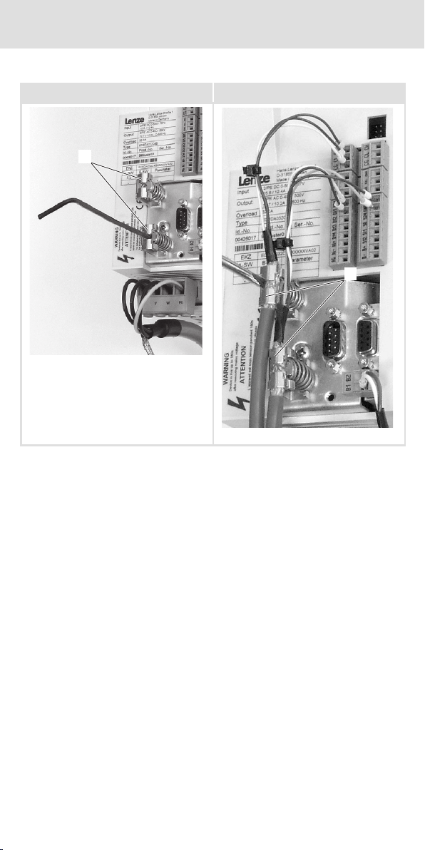
Mounting ECSxA axis module
Control cable/system bus cable
Control cable/system bus cable
Mounting the wire clamps Connecting the shield
5
ecs081 ecs082
Screw the wire clamps for the shield
connections of the control cable and the
system bus cable tightly onto the axis
module using a 3 mm Allan key.
Pressthe wire clamps for the shield
connections of the control cable and the
system bus cable down using a screw driver
(3 mm blade).
Place the cables under the wire clamps.
Remove the screw driver
6
EDKCSZS000 DE/EN/FR 4.1
15
Page 16

Mounting supply module ECSxE
External brake resistor/mains connection
External brake resistor/mains connection
The shield sheet for the mains cable is only required if the mains cable > 0.25 m.
Cable of the external brake resistor Mains cable
Insertthe M6 screws into the elongated
holes and attach the shield sheet.
Put the wire clamp for the shield connection
onto the cable of the external brake resistor
and press it down.
Move it towards the supply module until the
wire clamp snaps into place.
Puta cable tie around the cable of the
external brake resistor.
Fasten the cable to the shield sheet.
EDKCSZS000 DE/EN/FR 4.1
ecs089 ecs088
Insertthe M6 screws into the elongated
holes and attach the shield sheet
Put the wire clamp for the shield connection
onto the mains cable and press it down.
Move it towards the supply module until the
wire clamp snaps into place.
Puta cable tie around the mains cable.
Fasten the cable to the shield sheet.
16
Page 17

Mounting supply module ECSxE
Control cable/system bus cable
Control cable/system bus cable
Mounting the wire clamps Connecting the shield
6
ecs083 ecs084
Screw the wire clamps for the shield
connections of the control cable and the
system bus cable tightly onto the supply
module using a 3 mm Allan key.
Pressthe wire clamps for the shield
connections of the control cable and the
system bus cable down using a screw driver
(3 mm blade).
Place the cables under the wire clamps.
Remove the screw driver.
7
EDKCSZS000 DE/EN/FR 4.1
17
Page 18

Avant la mise en service
Ces instructions de montage
0Fig.0Tab. 0
Ces instructions de montage
ƒ décrivent le montage de la fixation de blindage ECSZS000X0B ;
ƒ contiennent les principales spécifications techniques relatives à la fixation de
blindage ECSZS000X0B ;
ƒ ne s’appliquent que conjointement avec les instructions de mise en service du
module d’axe ECSxA ou du module d’alimentation ECSxE.
Equipement livré
Utilisation de la fixation de blindage
ECSxA ECSxE
Tôle de blindage Câble moteur Câble réseau ou câble de la résistance de
Etrier de serrage
pour la reprise du
blindage
Etrier de serrage
pour la reprise du
blindage
Etrier de serrage
pour la reprise du
blindage
Câble moteur Câble réseau ou câble de la résistance de
Câble de commande, câble du
Bus Système
Pilotage du frein –
freinage externe
z En cas d’utilisation de câbles réseau
> 0,25 m et d’une résistance de
freinage externe, deux fixations de
blindage sont nécessaires.
freinage externe
Câble de commande, câble du Bus
Système
ecs070
EDKCSZS000 DE/EN/FR 4.1
18
Page 19

Câblage conforme CEM
Exempledecâblage
Exempledecâblage
ECSxA ECSxA
EDKCSZS000 DE/EN/FR 4.1
ecs085 ecs086
19
Page 20

Dimensions et alésages ECSxA et ECSxE
Encombrements
Dimensions et alésages ECSxA et ECSxE
ecs072 ecs073 ecs074
[mm] a a1 a2 b b1
Montage standard 19.5
Montage traversant le fond de l’armoire 18 39 57 28.5 112
Montage sur semelle de refroidissement 5.5 39 57 42.5 132
39
57 25.5 112
Dimensions et alésages ECSxE
ecs071 ecs076 ecs091
[mm] a a1 a2 b b1
Montage standard 19.5
Montage traversant le fond de l’armoire 18 39 57 28.5 112
Montage sur semelle de refroidissement 25.5 39 57 42.5 132
EDKCSZS000 DE/EN/FR 4.1
20
39
57 25.5 112
Page 21

Préparatifs
Préparer le câble de puissance
Préparer le câble de puissance
ECSxA
ECSxE
Raccordement au réseau
[mm] a b c d e f a b c e
Montage standard 490 380 80 90 6 50 240 90 80 6
Montage traversant le fond de
l’armoire
Montage sur semelle de
refroidissement
490 380 80 90 6 50 240 90 80 6
450 380 80 90 6 50 200 90 80 6
ECSxE
Raccordement de la résistance de freinage
externe
ecs090 ecs092
ECSxA ECSxE
ecs075
Préparer le câble de commande
[mm] a b c
Câble de commande 140 20 6
Câble du Bus Système 120 20 6
EDKCSZS000 DE/EN/FR 4.1
21
ecs080
Page 22

Montage module d’axe ECSxA
Câble moteur/”pilotage du frein”
Câble moteur/”pilotage du frein”
Monter la tôle de blindage
Insérer les vis M6 et fixer la tôle de blindage.
Fixer l’étrier de serrage pour la reprise du blindage ”pilotage du fr ein” à la tôle de blindage à
l’aide d’une clé pour vis à six pans creux de 3 mm.
Poser le blindage du câble moteur Poser le blindage ”pilotage du frein”
ecs077
Poserl’étrier de serrage pour la reprise du
blindage du câble moteur sur le câble,
l’enfoncer.
Déplacer en direction du module d’axe
jusqu’à ce qu’il s’emboîte dans la tôle de
blindage.
Enroulerle serre-câbles autour du câble
moteur.
Fixer ce dernier à la tôle de blindage.
EDKCSZS000 DE/EN/FR 4.1
ecs078 ecs079
Enfoncerl’étrier de serrage pour la reprise du
blindage ”pilotage du frein” à l’aide d’un
tournevis (3 mm).
Glisser le câble sous l’étrier de serrage.
Retirer le tournevis.
22
Page 23

Montage module d’axe ECSxA
Câbledecommande/câbleduBusSystème
Câbledecommande/câbleduBusSystème
Monter les étriers de serrage Poser le blindage
5
ecs081 ecs082
Visserles étriers de serrage pour la reprise du
blindage du câble de commande et du câble
du Bus Système sur le module d’axe à l’aide
d’une clé pour vis à six pans creux de 3 mm.
Enfoncerles étriers de serrage pour la reprise
du blindage du câble de commande et du
câble du Bus Système à l’aide d’un tournevis
(3 mm).
Glisser les câbles sous les étriers de serrage.
Retirer le tournevis.
6
EDKCSZS000 DE/EN/FR 4.1
23
Page 24

Montage module d’alimentation ECSxE
Résistance de freinage externe/raccordement au réseau
Résistance de freinage externe/raccordement au réseau
La tôle de blindage du câble réseau est uniquement nécessaire lorsque la longueur du câble
réseau>0,25m.
Câbledelarésistancedefreinageexterne Câble réseau
ecs089 ecs088
Insérerles vis M6 et fixer la tôle de blindage. Insérer les vis M6 et fixer la tôle de blindage.
Poserl’étrier de serrage pour la reprise du
blindage du câble de la résistance de freinage
externe sur le câble, l’enfoncer.
Déplacer en direction du module
d’alimentation jusqu’à ce qu’il s’emboîte
dans la tôle de blindage.
Enroulerle serre-câbles autour du câble de la
résistance de freinage externe.
Fixer le câble à la tôle de blindage.
EDKCSZS000 DE/EN/FR 4.1
Poserl’étrier de serrage pour la reprise du
blindage du câble réseau sur le câble,
l’enfoncer.
Déplacer en direction du module
d’alimentation jusqu’à ce qu’il s’emboîte
dans la tôle de blindage.
Enroulerle serre-câbles autour du câble
réseau.
Fixer le câble à la tôle de blindage.
24
Page 25

Montage module d’alimentation ECSxE
Câbledecommande/câbleduBusSystème
Câbledecommande/câbleduBusSystème
Monter les étriers de serrage Poser le blindage
6
ecs083 ecs084
Visserles étriers de serrage pour la reprise du
blindage du câble de commande et du câble
du Bus Système à l’aide d’une clé pour vis à
six pans creux de 3 mm sur le module
d’alimentation.
Enfoncerles étriers de serrage pour la reprise
du blindage du câble de commande et du
câble du Bus Système à l’aide d’un tournevis
(3 mm).
Glisser les câbles sous les étriers de serrage.
Retirer le tournevis.
7
EDKCSZS000 DE/EN/FR 4.1
25
Page 26

© 04/2010
Lenze Automation GmbH
)
Hans-Lenze-Str. 1
D-31855 Aerzen
Germany
+49 (0)51 54 / 82-0
¬
+49(0)5154/82-2800
|
Lenze@Lenze.de
Þ
www.Lenze.com
Service Lenze Service GmbH
Breslauer Straße 3
D-32699 Extertal
Germany
00 80 00 / 24 4 68 77 (24 h helpline)
¬
+49 (0)51 54 / 82-11 12
|
Service@Lenze.de
EDKCSZS000.AöhDE/EN/FR4.1TD00
10987654321
 Loading...