

Page 1
EDKCSEK002
.Cka
Ä.Ckaä
Montageanleitung
Mounting Instructions
Instructions de montage
ECS
ECSEKxxx
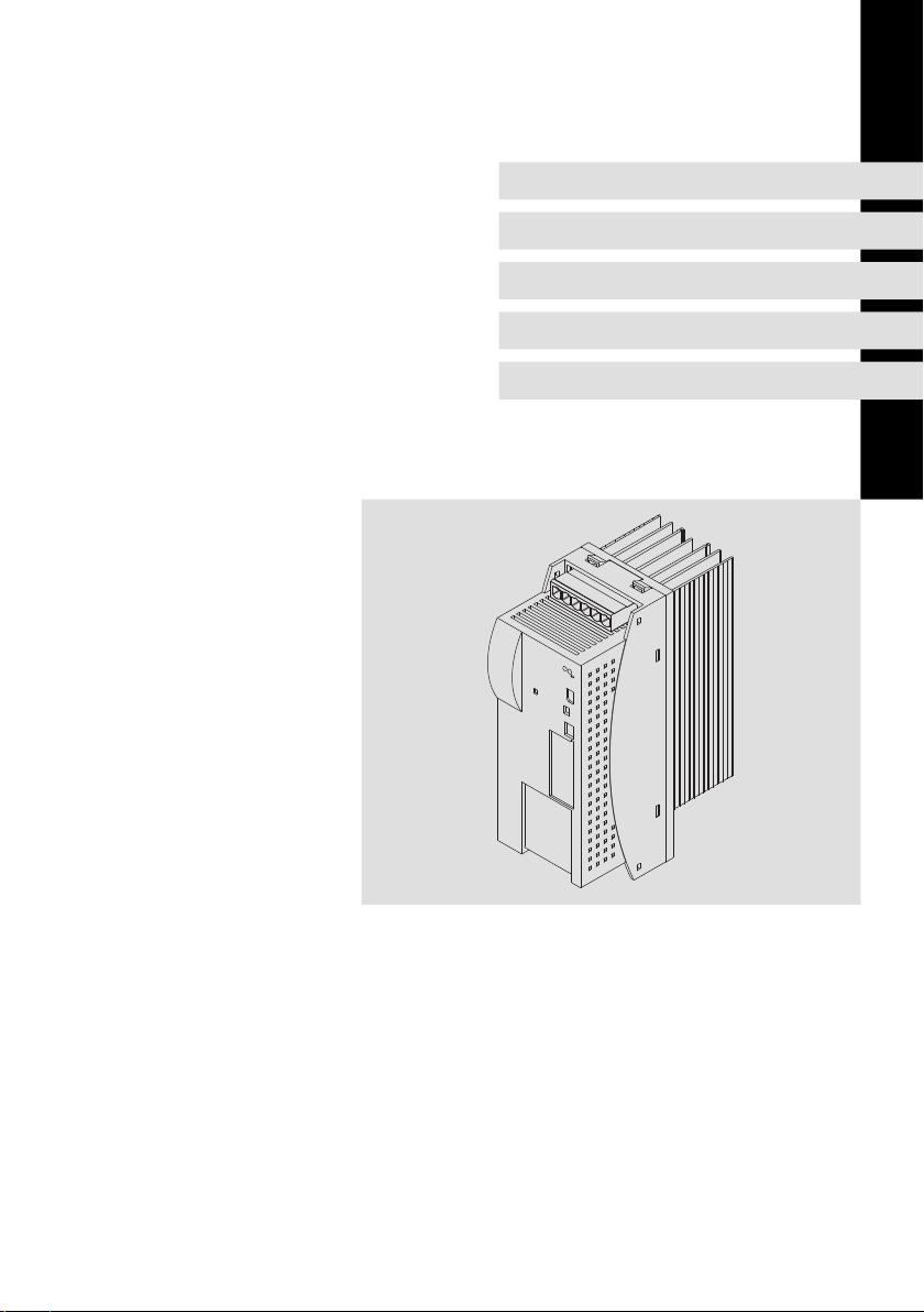
Kondensatormodul ”Einbaugerät”
Panel-mounted capacitor module
Module condensateur en montage sur panneau
Page 2

Lesen Sie zuerst diese Anleitung, bevor Sie mit den Arbeiten beginnen!
Beachten Sie die enthaltenen Sicherheitshinweise.
Please read these instructions before you start working!
Follow the enclosed safety instructions.
Veuillez lire attentivement cette documentation avant toute action !
Les consignes de sécurité doivent impérativement être respectées.
Page 3

ECSEK_001A
Page 4

0Abb.0Tab. 0
Lieferumfang
Position Beschreibung Anzahl
Kondensatormodul ECSEKxxx 1
Beipack mit Befestigungsmaterial 1
Montageanleitung 1
Bohrschablone 1
Hinweis!
Die Steckverbinder ECSZK000X0B müssen gesondert bezogen werden.
Anschlüsse und Schnittstellen
Position Beschreibung ausführliche
X23 Anschlüsse
X26 Steueranschluss
Zwischenkreisspannung
PE
Überbrückung der Ladestrombegrenzung
Informationen
23
26
4
EDKCSEK002 DE/EN/FR 2.0
Page 5

Diese Anleitung ist gültig für Kondensatormodule ECSEKxxx ab dem Gerätestand:
ECS E K xxx X 4 B xxx 1A
Gerätetyp
Bauform
E = Einbaugerät IP20
D = Durchstoßtechnik (thermische Separierung)
C = Cold-Plate-Technik
Kapazität
001 = 705 µF (±20 %)
002 = 1410 µF (±20 %)
Spannungsklasse
4 = 400 V/480 V
Technische Ausführung
B = Standard
Variante
Stand Hardware
1A oder höher
Tipp!
Informationen und Hilfsmittel rund um die Lenze-Produkte finden Sie im
Download-Bereich unter
http://www.Lenze.com
0Abb.0Tab. 0
EDKCSEK002 DE/EN/FR 2.0
5
Page 6

Inhalti
1 Sicherheitshinweise 7. . . . . . . . . . . . . . . . . . . . . . . . . . . . . . . . . . . . . . . . . . . . . . .
1.1 Allgemeine Sicherheits- und Anwendungshinweise für
Lenze-Kondensatormodule 7. . . . . . . . . . . . . . . . . . . . . . . . . . . . . . . . . . .
1.2 Restgefahren 10. . . . . . . . . . . . . . . . . . . . . . . . . . . . . . . . . . . . . . . . . . . . . .
1.3 Sicherheitshinweise für die Installation nach UL oder UR 11. . . . . . . . . .
1.4 Verwendete Hinweise 12. . . . . . . . . . . . . . . . . . . . . . . . . . . . . . . . . . . . . . .
2 Technische Daten 14. . . . . . . . . . . . . . . . . . . . . . . . . . . . . . . . . . . . . . . . . . . . . . . . .
2.1 Allgemeine Daten und Einsatzbedingungen 14. . . . . . . . . . . . . . . . . . . .
2.2 Bemessungsdaten 16. . . . . . . . . . . . . . . . . . . . . . . . . . . . . . . . . . . . . . . . . .
3 Mechanische Installation 17. . . . . . . . . . . . . . . . . . . . . . . . . . . . . . . . . . . . . . . . . . .
3.1 Wichtige Hinweise 17. . . . . . . . . . . . . . . . . . . . . . . . . . . . . . . . . . . . . . . . . .
3.2 Montage mit Befestigungsschienen (Standard-Einbau) 18. . . . . . . . . . . .
3.2.1 Abmessungen 18. . . . . . . . . . . . . . . . . . . . . . . . . . . . . . . . . . . .
3.2.2 Montageschritte 19. . . . . . . . . . . . . . . . . . . . . . . . . . . . . . . . . .
4 Elektrische Installation 20. . . . . . . . . . . . . . . . . . . . . . . . . . . . . . . . . . . . . . . . . . . . .
4.1 EMV-gerechte Installation
(Aufbau des CE-typischen Antriebssystems) 20. . . . . . . . . . . . . . . . . . . . .
4.2 Leistungsanschlüsse 23. . . . . . . . . . . . . . . . . . . . . . . . . . . . . . . . . . . . . . . .
4.2.1 Anschluss an den DC-Zwischenkreis (+UG, -UG) 25. . . . . . . . .
4.3 Steueranschluss X26 26. . . . . . . . . . . . . . . . . . . . . . . . . . . . . . . . . . . . . . . .
4.4 Verdrahtung 27. . . . . . . . . . . . . . . . . . . . . . . . . . . . . . . . . . . . . . . . . . . . . . .
4.4.1 Betrieb mit Versorgungsmodul ECSxE 27. . . . . . . . . . . . . . . . .
4.4.2 Betrieb mit anderem Versorger 29. . . . . . . . . . . . . . . . . . . . . .
5 Installation überprüfen 30. . . . . . . . . . . . . . . . . . . . . . . . . . . . . . . . . . . . . . . . . . . .
6
EDKCSEK0 02 DE/E N/FR 2 .0
Page 7

Sicherheitshinweise
Allgemeine Sicherheits- und Anwendungshinweise
1 Sicherheitshinweise
1.1 Allgemeine Sicherheits- und Anwendungshinweise für
Lenze-Kondensatormodule
(gemäß Niederspannungsrichtlinie 73/23/EWG)
Allgemein
Lenze-Kondensatormodule können während desBetriebs - ihrer Schutzart entsprechend - spannungsführende Teile haben. Oberflächen können heiß sein.
Bei unzulässigem Entfernen der erforderlichen Abdeckung, bei unsachgemäßem Einsatz, bei falscher Installation oder Bedienung besteht die Gefahr von
schweren Personen- oder Sachschäden.
Weitere Informationen entnehmen Sie der Dokumentation.
Alle Arbeiten zum Transport, zur Installation, zur Inbetriebnahme und zur In-
standhaltung darf nur qualifiziertesFachpersonal ausführen(IE 364 bzw.CENELEC HD 384 oder DIN VDE 0100 undIEC-Report 664 oder DIN VDE 0110 und nationale Unfallverhütungsvorschriften beachten).
Qualifiziertes Fachpersonal im Sinne dieser grundsätzlichen Sicherheitshinweise sind Personen, die mit Aufstellung, Montage, Inbetriebsetzung und Betrieb desProdukts vertrautsind unddie überdie ihrer Tätigkeitentsprechenden
Qualifikationen verfügen.
1
EDKCSEK002 DE/EN/FR 2.0
7
Page 8

1
Sicherheitshinweise
Allgemeine Sicherheits- und Anwendungshinweise
Bestimmungsgemäße Verwendung
Kondensatormodule sindKomponenten, diezum Einbauin elektrische Anlagen
oder Maschinen bestimmt sind. Sie sind keine Haushaltsgeräte, sondern als
Komponenten ausschließlich für die Verwendung zur gewerblichen Nutzung
bzw. professionellen Nutzung im Sinne derEN 61000-3-2 bestimmt. Die Dokumentation enthält Hinweise zur Einhaltung der Grenzwerte nach
EN 61000-3-2.
Bei Einbau der Kondensatormodule in Maschinen ist die Inbetriebnahme (d. h.
die Aufnahme des bestimmungsgemäßen Betriebs) solangeuntersagt, bisfestgestellt wurde, dass die Maschine den Bestimmungen der EG-Richtlinie
98/37/EG (Maschinenrichtlinie) entspricht; EN 60204 beachten.
Die Inbetriebnahme (d. h. die Aufnahme des bestimmungsgemäßen Betriebs)
ist nur bei Einhaltung der EMV-Richtlinie (89/336/EWG) erlaubt.
Die Kondensatormodule erfüllen die Anforderungen der Niederspannungsrichtlinie 73/23/EWG. Die harmonisierten Normen der Reihe EN 61800-5-1 /
DIN VDE 0160 werden für die Kondensatormodule angewendet.
Die technischenDaten unddie Angabenzu Anschlussbedingungen entnehmen
Sie dem Leistungsschild und der Dokumentation. Halten Sie diese unbedingt
ein.
Warnung: Die Kondensatormodule sind Produkte mit eingeschränkter Erhältlichkeit nachEN 61800-3. DieseProdukte können im WohnbereichFunkstörungen verursachen.In diesem Fall kann es für den Betreiber erforderlich sein, entsprechende Maßnahmen durchzuführen.
Transport, Einlagerung
Beachten Sie die Hinweise für Transport, Lagerung und sachgemäße Handhabung.
Halten Sie die klimatischen Bedingungen gemäß den technischen Daten ein.
Aufstellung
Sie müssen dieKondensatormodule nachden Vorschriftender zugehörigenDokumentation aufstellen und kühlen.
SorgenSie fürsorgfältige Handhabungund vermeiden Siemechanische Überlastung. Verbiegen Siebei Transport und Handhabung weder Bauelemente noch
ändern Sie Isolationsabstände.Berühren Siekeine elektronischenBauelemente
und Kontakte.
Kondensatormodule enthalten elektrostatisch gefährdete Bauelemente, die
Sie durch unsachgemäße Handhabung leicht beschädigen können. Beschädigen oder zerstörenSie keineelektrischen Komponenten,da Siedadurch IhreGesundheit gefährden können!
8
EDKCSEK002 DE/EN/FR 2.0
Page 9

Sicherheitshinweise
Allgemeine Sicherheits- und Anwendungshinweise
Elektrischer Anschluss
Beachten Siebei Arbeiten an unter Spannungstehenden Kondensatormodulen
die geltenden nationalen Unfallverhütungsvorschriften (z. B. VBG 4).
Führen Sie die elektrische Installation nach den einschlägigen Vorschriften
durch (z. B. Leitungsquerschnitte, Absicherungen, Schutzleiteranbindung). Zusätzliche Hinweise enthält die Dokumentation.
Die Dokumentation enthält Hinweise für die EMV-gerechte Installation (Schirmung, Erdung, Anordnungvon Filtern und Verlegung der Leitungen). Beachten
Sie dieseHinweise ebensobei CE-gekennzeichnetenKondensatormodulen. Der
Hersteller der Anlage oder Maschine ist verantwortlich für die Einhaltung der
durch die EMV-Gesetzgebung geforderten Grenzwerte.
Betrieb
Sie müssen Anlagen mit eingebauten Kondensatormodulen ggf. mit zusätzlichen Überwachungs- undSchutzeinrichtungen gemäß denjeweils gültigen Sicherheitsbestimmungen ausrüsten (z. B. Gesetzüber technische Arbeitsmittel,
Unfallverhütungsvorschriften). Sie dürfen die Kondensatormodule an Ihre Anwendung anpassen. Beachten Sie dazu die Hinweise in der Dokumentation.
Nachdem das Kondensatormodul von der Versorgungsspannung getrennt ist,
dürfen Sie spannungsführende Geräteteile und Leistungsanschlüsse nicht sofort berühren, weil Kondensatoren aufgeladen sein können. Beachten Sie dazu
die entsprechenden Hinweisschilder auf dem Kondensatormodul.
Halten Sie während des Betriebs alle Schutzabdeckungen und Türen geschlossen.
Hinweis für UL-approbierte Anlagen mit eingebauten Kondensatormodulen:
UL warnings sind Hinweise, die nurfür UL-Anlagen gelten. Die Dokumentation
enthält spezielle Hinweise zu UL.
Wartung und Instandhaltung
Die Kondensatormodule sind wartungsfrei, wenn die vorgeschriebenen Einsatzbedingungen eingehalten werden.
Bei verunreinigter Umgebungsluft können die Kühlflächen des Kondensatormoduls verschmutzen oder Kühlöffnungen verstopft werden. Bei diesen Betriebsbedingungen deshalb regelmäßig die Kühlflächen und Kühlöffnungen
reinigen. Dazu niemals scharfe oder spitze Gegenstände verwenden!
Entsorgung
Metalle und Kunststoffe zur Wiederverwertung geben. Bestückte Leiterplatten
fachgerecht entsorgen.
Beachten Sie unbedingt die produktspezifischen Sicherheits- und
Anwendungshinweise in dieser Anleitung!
1
EDKCSEK002 DE/EN/FR 2.0
9
Page 10

1
1.2 Restgefahren
Sicherheitshinweise
Restgefahren
Personenschutz
ƒ
Überprüfen Sie vor Arbeiten am Kondensatormodul, ob alle
Leistungsklemmen spannungslos sind, denn
–
nach dem Abschalten der Netzspannung am Versorgungsmodul führen
die Leistungsklemmen +UG und -UG noch mindestens 3 Minuten
gefährliche Spannung.
–
bei gestopptem Motor führen die Leistungsklemmen +UG und -UG
gefährliche Spannung.
ƒ
Im Fehlerfall (Körper- oder Erdschluss) kann ein Fehler-Gleichstrom im
Schutzleiter verursacht werden. Wird für den Schutz im Falle einer direkten
oder indirekten Berührung ein Fehlerstrom-Schutzschalter
(Differenzstromgerät) verwendet, ist auf der Stromversorgungsseite nur
ein Fehlerstrom-Schutzschalter vom Typ B zulässig. Anderenfalls muss eine
andere Schutzmaßnahme angewendet werden, wie z. B. Trennung von der
Umgebung durch doppelte oder verstärkte Isolierung oder Trennung vom
Versorgungsnetz durch einen Transformator.
Geräteschutz
ƒ
Alle steckbaren Anschlussklemmen nur im spannungslosen Zustand
aufstecken oder abziehen.
ƒ
Polarität der Leistungsklemmen +UG, -UG und PE beim Verdrahten
beachten.
ƒ
Erst wenn das Versorgungsmodul im Leistungsverbund betriebsbereit ist
und die Ladestrombegrenzung überbrückt ist, darf Leistung umgewandelt
werden. Sonst kann die Ladestrombegrenzung zerstört werden.
ƒ
Bei aktiver Ladestrombegrenzung kann zyklisches Ein- und Ausschalten der
Netzspannung am Versorgungsmodul das Kondensatormodul überlasten
und zerstören. Deshalb müssen bei zyklischem Netzschalten über einen
längeren Zeitraum zwischen zwei Einschaltvorgängen mindestens
3 Minuten vergehen.
10
EDKCSEK0 02 DE/E N/FR 2 .0
Page 11

Sicherheitshinweise
Sicherheitshinweise für die Installation nach ULoder U
1
R
1.3 Sicherheitshinweise für die Installation nach ULoder U
Warnings!
General markings:
ƒ
Use 60/75 °C or 75 °C copper wire only.
ƒ
Maximum ambient temperature 55 °C, with reduced output
current.
Terminal tightening torque of lb-in (Nm)
Terminal lb-in Nm
X 23 10.6 ... 13.3 1.2 ... 1.5
X 26 4.4 ... 7.1 0.5 ... 0.8
Wiring diagram AWG
Terminal AWG
X 23 12 ... 8
X 26 24 ... 12
R
EDKCSEK0 02 DE/EN/FR 2.0
11
Page 12

1
1.4 Verwendete Hinweise
Sicherheitshinweise
Verwendete Hinweise
Um auf Gefahren und wichtige Informationen hinzuweisen, werden in dieser
Dokumentation folgende Piktogramme und Signalwörter verwendet:
Sicherheitshinweise
Aufbau der Sicherheitshinweise:
Gefahr!
(kennzeichnet die Art und die Schwere der Gefahr)
Hinweistext
(beschreibt die Gefahr und gibt Hinweise, wie sie vermieden werden
kann)
Piktogramm und Signalwort Bedeutung
Gefahr!
Gefahr!
Stop!
Anwendungshinweise
Gefahr von Personenschäden durch gefährliche elektrische Spannung
Hinweis auf eine unmittelbar drohendeGefahr, die den
Tod oder schwere Verletzungen zur Folge haben kann,
wenn nicht die entsprechendenMaßnahmen getroffen
werden.
Gefahr von Personenschäden durch eine allgemeine
Gefahrenquelle
Hinweis auf eine unmittelbar drohendeGefahr, die den
Tod oder schwere Verletzungen zur Folge haben kann,
wenn nicht die entsprechendenMaßnahmen getroffen
werden.
Gefahr von Sachschäden
Hinweis auf eine mögliche Gefahr, die Sachschäden zur
Folge haben kann, wenn nicht die entsprechenden Maßnahmen getroffen werden.
12
Piktogramm und Signalwort Bedeutung
Hinweis!
Tipp!
Wichtiger Hinweis für die störungsfreie Funktion
Nützlicher Tipp für die einfache Handhabung
Verweis auf andere Dokumentation
EDKCSEK002 DE/EN/FR 2.0
Page 13

Sicherheitshinweise
Verwendete Hinweise
Spezielle Sicherheitshinweise und Anwendungshinweise für UL und UR
Piktogramm und Signalwort Bedeutung
Sicherheitshinweis oder Anwendungshinweis für den
Betrieb eines UL-approbierten Geräts in UL-approbier-
Warnings!
Warnings!
ten Anlagen.
Möglicherweise wird das Antriebssystem nicht UL-gerecht betrieben, wenn nicht die entsprechenden Maßnahmen getroffen werden.
Sicherheitshinweis oder Anwendungshinweis für den
Betrieb eines UR-approbierten Geräts in UL-approbierten Anlagen.
Möglicherweise wird das Antriebssystem nicht UL-gerecht betrieben, wenn nicht die entsprechenden Maßnahmen getroffen werden.
1
EDKCSEK002 DE/EN/FR 2.0
13
Page 14

2
Technische Daten
Allgemeine Daten und Einsatzbedingungen
2 Technische Daten
2.1 Allgemeine Daten und Einsatzbedingungen
Normen und Einsatzbedingungen
Konformität CE Niederspannungsrichtlinie (2006/95/EG)
Approbationen UL 508C Power Conversion Equipment
Verpackung (DIN 4180) Versandverpackung
Einbau Einbau in Schaltschrank
Einbaulage senkrechthängend
Einbaufreiräume
Umweltbedingungen
Klima 3k3 nach IEC/EN 60721-3-3
Lagerung IEC/EN 60721-3-1 1K3 (-25 ... + 55 °C)
Transport IEC/EN 60721-3-2 2K3 (-25 ... +70 °C)
Betrieb IEC/EN 60721-3-3 3K3 (0 ... + 55 °C)
Aufstellhöhe 0 ... 4000 m üNN
Verschmutzung VDE 0110 Teil 2 Verschmutzungsgrad 2
Vibrationsfestigkeit Beschleunigungsfest bis 0,7 g (Germanischer Lloyd, allgemeine Bedingungen)
oberhalb
unterhalb
seitlich ohne Abstand anreihbar
Betauung, Spritzwasser und Eisbildung
nicht zulässig.
≥
65 mm
≥
65 mm
mit Schirmbefestigungs-Set ECSZS000X0B: > 195 mm
Underwriter Laboratories (File No. E132659)
für USA und Kanada
Luftdruck: 86 ... 106 kPa
Über +40 °C: Ausgangs-Bemessungsstrom um 2 %/°C reduzieren.
Über 1000 m üNN: Ausgangs-Bemessungsstrom um 5 %/1000 m reduzieren.
Über 2000 m üNN: Einsatz nur erlaubt in Umgebungen mit Überspannungskategorie II
14
EDKCSEK002 DE/EN/FR 2.0
Page 15

Technische Daten
Allgemeine Daten und Einsatzbedingungen
Allgemeine elektrische Daten
EMV Einhaltung der Anforderungen nach EN 61800-3
Störaussendung Einhaltung der Grenzwertklasse A nach EN 55011
Störfestigkeit
Isolationsfestigkeit Überspannungskategorie III nach VDE 0110
Schutzart IP 20 (NEMA 250 Typ 1) bei
Schutzisolierung von Steuerschaltkreisen Schutztrennung vom Netz
1)
Die Störfestigkeit in den genannten Schärfegraden muss durch den Schaltschrank
gewährleistet sein! Der Anwender muss die Einhaltung der genannten Schärfegrade
prüfen!
(erreicht mit anwendungstypischem Summenfilter)
Anforderungen nach EN 61800-3
Anforderung Norm Schärfegrade
1)
ESD
leitungsgeführte Hochfrequenz
HF-Einstrahlung (Gehäuse)
Burst EN 61000-4-4 3/4, d. h. 2 kV/5 kHz
Surge (Stoßspannung
auf Netzleitung)
Standardmontage (Einbaugerät)
Montage in Cold-Plate-Technik
Montage mit thermischer Separierung (Durchstoß-Technik), IP54
auf der Kühlkörperseite
Doppelte/Verstärkte Isolierung nach EN 61800-5-1
Bemessungs-Isolationsspannung 300 V x√2
EN 61000-4-2 3, d. h.
EN 61000-4-6 10 V; 0.15 ... 80 MHz
EN 61000-4-3 3, d. h. 10 V/m;
80 ... 1000 MHz
EN 61000-4-5 3, d. h. 1.2/50µs
8 kV bei Luftentladung
6 kV bei Kontaktentladung
1 kV Phase-Phase
2 kV Phase-PE
2
EDKCSEK002 DE/EN/FR 2.0
15
Page 16

2
Technische Daten
Bemessungsdaten
2.2 Bemessungsdaten
Bemessungsdaten Typ ECSxK001xxx ECSxK002xxx
Daten für Betrieb mit vorgeschaltetem
Versorgungsmodul an Netzspannung
Zwischenkreisspannung UZK[V] 0 ... 770
AC-Bemessungsstrom IN[A] 17,5 35
Bemessungsleistung PB[kW] 10 20
Bemessungsleistung mit Netzdrossel PBN[kW] 14 28
Kapazität C [µF] 705 (±20 %) 1410 (±20 %)
Zeitkonstante zum Aufladen der Kondensatoren
Ladezeit der Kondensatoren nach Netzeinschalten
Gewicht
Abmessungen
ECSEKxxx m [kg] 2,1 3,2
ECSDKxxx m [kg] 2,1 3,2
ECSCKxxx m [kg] 2,4 3,4
ECSEKxxx (B x H x T) [mm] 88,5 x 247 x 176 132 x 247 x 176
ECSDKxxx (B x H x T) [mm] 88,5 x 247 x 176 132 x 247 x 176
ECSCKxxx (B x H x T) [mm] 88,5 x 282 x 123 132 x 282 x 123
U
[V] 400 480 400 480
Netz
τ
[ms]
t
[s] 1
K_laden
150
16
EDKCSEK002 DE/EN/FR 2.0
Page 17

3 Mechanische Installation
3.1 Wichtige Hinweise
ƒ
Kondensatormodule der Reihe ECS verfügen über die Schutzart IP20 und
sind daher nur für den Einbau in Schaltschränken bestimmt.
ƒ
Bei verunreinigter Kühlluft (Staub, Flusen, Fette, aggressive Gase):
–
Ausreichende Gegenmaßnahmen treffen, z. B. separate Luftführung,
Einbau von Filtern, regelmäßige Reinigung.
ƒ
Mögliche Einbaulagen:
–
Senkrecht an der Montageplatte
–
Zwischenkreisanschlüsse (X23) oben
–
Anschluss zur Überbrückung der Ladestrombegrenzung (X26) unten
ƒ
Halten Sie die angegebenen Einbaufreiräume oberhalb und unterhalb zu
anderen Installationen ein!
–
Bei Verwendung des Schirmbefestigungs-Set ECSZS000X0B ist ein
zusätzlicher Freiraum erforderlich.
–
Achten Sie auf ungehinderten Zutritt der Kühlluft und ungehinderten
Austritt der Abluft.
–
Sie können mehrere Module der Reihe ECS im Schaltschrank ohne
Zwischenraum nebeneinander befestigen.
ƒ
Die Montageplatte des Schaltschranks muss elektrisch leitfähig sein.
ƒ
Bei dauerhaften Schwingungen oder Erschütterungen den Einsatz von
Schwingungsdämpfern prüfen.
Mechanische Installation
Wichtige Hinweise
3
EDKCSEK002 DE/EN/FR 2.0
17
Page 18

3
h
h
a
g
g
a
d1
d
g
g
³ 65mm
e
³ 65mm
d1
d
b
b
0
1
Mechanische Installation
Montage mit Befestigungsschienen (Standard-Einbau)
Abmessungen
3.2 Montage mit Befestigungsschienen (Standard-Einbau)
3.2.1 Abmessungen
Hinweis!
Montage mit Schirmbefestigung ECSZS000X0B:
ƒ
Einbaufreiraum unterhalb des Moduls > 195 mm
18
Abb. 3-1 Abmessungen bei Bauform ”Einbaugerät”
Kondensatormodul Maße [mm]
Typ Bau-
ECSEK001
ECSEK002
größe
a b d d1 e g h
88,5
131
240 276 260 176
ECSXK005
6,5
(M6)
EDKCSEK002 DE/EN/FR 2.0
10
Page 19

Montage mit Befestigungsschienen (Standard-Einbau)
3.2.2 Montageschritte
So montieren Sie das Kondensatormodul:
1. Befestigungsbohrungen auf Montagefläche vorbereiten.
–
Dazu Bohrschablone anlegen.
2. Entnehmen Sie die Befestigungsschienen dem Beipack im Karton.
3. Schieben Sie die Schienen in die Nuten des Kühlkörpers:
–
von oben: lange Seite einschieben.
–
von unten: kurze Seite einschieben.
4. Kondensatormodul auf der Montageplatte befestigen.
Mechanische Installation
Montageschritte
3
EDKCSEK002 DE/EN/FR 2.0
19
Page 20

4
Elektrische Installation
EMV-gerechte Installation (Aufbau des CE-typischen Antriebssystems)
4 Elektrische Installation
4.1 EMV-gerechte Installation (Aufbau des CE-typischen Antriebssystems)
Allgemeine Hinweise
ƒ
Die elektromagnetische Verträglichkeit einer Maschine ist abhängig von
der Art und Sorgfalt der Installation. Beachten Sie besonders:
–
Aufbau
–
Filterung
–
Schirmung
–
Erdung
ƒ
Bei abweichender Installation ist für die Bewertung der Konformität zur
EMV-Richtlinie die Überprüfung der Maschine oder Anlage auf Einhaltung
der EMV-Grenzwerte erforderlich. Dies gilt z. B. bei:
–
Verwendung ungeschirmter Leitungen
–
Verwendung von Sammel-Entstörfiltern anstelle der zugeordneten
Funk-Entstörfilter
–
Betrieb ohne Funk-Entstörfilter
ƒ
Die Verantwortung für die Einhaltung der EMV-Richtlinie in der
Maschinenanwendung liegt beim Weiterverwender.
–
Wenn Sie die folgenden Maßnahmen beachten, können Sie davon
ausgehen, dass beim Betrieb der Maschine keine vom Antriebssystem
verursachten EMV-Probleme auftreten und die EMV-Richtlinie bzw. das
EMV-Gesetz erfüllt ist.
–
Werden in der Nähe der ECS-Module Geräte betrieben, die der
CE-Anforderung hinsichtlich der Störfestigkeit EN 61000-6-2 nicht
genügen, können diese Geräte durch die ECS-Module
elektromagnetisch beeinträchtigt werden.
20
EDKCSEK002 DE/EN/FR 2.0
Page 21

Elektrische Installation
EMV-gerechte Installation (Aufbau des CE-typischen Antriebssystems)
Aufbau
ƒ
ECS-Module, Funk-Entstörfilter und Netzdrossel großflächig mit geerdeter
Montageplatte verbinden:
–
Montageplatten mit elektrisch leitender Oberfläche (verzinkt oder
rostfreier Stahl) erlauben eine dauerhafte Verbindung.
–
Lackierte Platten sind nicht geeignet für die EMV-gerechte Installation.
ƒ
Verwendung des Kondensatormoduls ECSxK...:
–
Installieren Sie das Kondensatormodul zwischen dem
Versorgungsmodul und dem/den Achsmodul(en).
–
Ist die Gesamtleitungslänge im Zwischenkreisverbund > 5 m,
installieren Sie das Kondensatormodul möglichst nah am Achsmodul
mit der größten Leistung.
ƒ
Verwendung mehrerer Montageplatten:
–
Montageplatten großflächig leitend miteinander verbinden (z. B. mit
Kupferbändern).
ƒ
Beim Verlegen der Leitungen auf räumliche Trennung der Motorleitung
von Signal- und Netzleitungen achten.
ƒ
Eine gemeinsame Klemmen-/Steckerleiste für Netzeingang und
Motorausgang vermeiden.
ƒ
Leitungsführung möglichst dicht am Bezugspotenzial. Frei schwebende
Leitungen wirken wie Antennen.
Filterung
Verwenden Sie nurdie denVersorgungssmodulen zugeordneten Funk-Entstörfilter und Netzdrosseln:
ƒ
Funk-Entstörfilter reduzieren unzulässige hochfrequente Störgrößen auf
ein zulässiges Maß.
ƒ
Netzdrosseln reduzieren niederfrequente Störgrößen, die insbesondere
durch die Motorleitungen bedingt werden und von deren Länge abhängig
sind.
4
EDKCSEK002 DE/EN/FR 2.0
21
Page 22

4
Elektrische Installation
EMV-gerechte Installation (Aufbau des CE-typischen Antriebssystems)
Schirmung
ƒ
Am Achsmodul den Schirm der Motorleitung
–
mit der Schirmbefestigung ECSZS000X0B auflegen.
–
großflächig mit der Montageplatte unterhalb des Achsmoduls
verbinden.
–
Empfehlung: Schirm mit Erdungsschellen auf metallisch blanken
Montageflächen ausführen.
ƒ
Bei Schützen, Motorschutzschalter oder Klemmen in der Motorleitung:
–
Die Schirme der dort angeschlossenen Leitungen miteinander
verbinden und ebenfalls großflächig mit der Montageplatte
kontaktieren.
ƒ
Im Klemmenkasten des Motors oder am Motorgehäuse den Schirm
großflächig mit PE verbinden:
–
Metallische Kabelverschraubungen am Motorklemmkasten
gewährleisten eine großflächige Verbindung des Schirms mit dem
Motorgehäuse.
ƒ
UG-Leitungen und Steuerleitungen ab 0,3 m Länge abschirmen:
–
Schirme digitaler Steuerleitungen beidseitig auflegen.
–
Schirme analoger Steuerleitungen einseitig auflegen.
–
Schirme auf kürzestem Weg mit den Schirmanschlüssen am Achsmodul
verbinden.
ƒ
Einsatz der ECS-Module in Wohngebieten:
–
Zur Begrenzung der Störstrahlung zusätzliche Schirmdämpfung ≥ 10 dB
vorsehen. Diese wird in der Regel durch Einbau in handelsübliche,
geschlossene, metallische und geerdete Schaltschränke oder -kästen
erreicht.
Erdung
ƒ
Alle metallisch leitfähigen Komponenten (z. B. ECS-Module,
Funk-Entstörfilter, Motorfilter, Netzdrosseln) durch entsprechende
Leitungen von einem zentralen Erdungspunkt (PE-Schiene) erden.
ƒ
Die in den Sicherheitsvorschriften definierten Mindestquerschnitte
einhalten:
–
Für die EMV ist nicht der Leitungsquerschnitt, sondern die Oberfläche
der Leitung und der flächigen Kontaktierung entscheidend.
22
EDKCSEK002 DE/EN/FR 2.0
Page 23

4.2 Leistungsanschlüsse
Stop!
Kein Geräteschutz gegen zu hohe Netzspannung
Der Netzeingang ist intern nicht abgesichert.
Mögliche Folgen:
ƒ
Zerstörung des Gerätes bei zu hoher Netzspannung.
Schutzmaßnahmen:
ƒ
Beachten Sie die maximal zulässige Netzspannung.
ƒ
Sichern Sie das Gerät netzseitig fachgerecht gegen
Netzschwankungen und Spannungsspitzen ab.
Stop!
Das Kondensatormodul ist ausschließlich für den Betrieb an
symmetrischen Netzen zugelassen. Ein Betrieb an
Außenleiter-geerdeten Netzen ist nicht zulässig.
ƒ
Alle Leistungsanschlüsse sind steckbar ausgeführt und kodiert. Die
Steckverbinder für Kondensatormodule ECSZK000X0B müssen gesondert
bezogen werden.
ƒ
Installation der Leitungen nach EN 60204-1.
ƒ
Die verwendeten Leitungen müssen den geforderten Approbationen am
Einsatzort entsprechen (z. B. VDE, UL usw.).
Klemmenbelegung
Elektrische Installation
Leistungsanschlüsse
4
Klemme Funktion Elektrische Daten
X23 Anschluss Zwischenkreisspannung
X23/+UG
X23/+UG
X23/-UG
X23/-UG
X23/PE
X23/PE
EDKCSEK002 DE/EN/FR 2.0
positive Einspeisung Zwischenkreisspannung
negative Einspeisung Zwischenkreisspannung
Anschluss Erde
anwendungs- und typabhängig
0 ... 770 V
bis 24,5 A (16)
23
Page 24

4
Elektrische Installation
Leistungsanschlüsse
Leitungsquerschnitte und Schraubenanzugsmomente
Leitungstyp
Klemmenleiste X23
starr -
flexibel
Aderendhülse mögliche Leitungs-
ohne Aderendhülse
mit Aderendhülse
mit TWIN-Aderendhülse
querschnitte
0,2 ... 10 mm
(AWG 24 ... 8)
0,2 ... 10 mm
(AWG 24 ... 8)
0,25 ... 6 mm
(AWG 22 ... 10)
0,25 ... 4 mm
(AWG 22 ... 12)
2
2
2
2
Anzugsmoment Abisolierlänge
1,2 ... 1,5 Nm
(10.6 ... 13.3 lb-in)
5 mm
Geschirmte Leitungen
Folgende Faktoren bestimmen maßgeblich die Wirkung der geschirmten Leitungen:
ƒ
Gute Schirmanbindung
–
Schirm großflächig auflegen
ƒ
Niedriger Schirmwiderstand
–
Nur Schirme mit verzinntem oder vernickeltem Kupfergeflecht
verwenden (Schirme aus Stahlgeflecht sind ungeeignet).
ƒ
Hoher Überdeckungsgrad des Schirmgeflechts
–
Mindestens 70 ... 80 % mit 90° Überdeckungswinkel
Klemmbügel und Schirmblech enthält die Schirmbefestigung ECSZS000X0B.
24
EDKCSEK002 DE/EN/FR 2.0
Page 25

Elektrische Installation
Anschluss an den DC-Zwischenkreis (+UG, -UG)
4.2.1 Anschluss an den DC-Zwischenkreis (+UG, -UG)
ƒ
Bei einer Gesamtleitungslänge > 20 m installieren Sie ein Achsmodul oder
ein Kondensatormodul direkt am Versorgungsmodul.
ƒ
±UG-Leitungen verdrillt und möglichst kurz ausführen. Auf
kurzschlusssichere Verlegung achten!
ƒ
Leitungslänge (Modul ↔ Modul) > 30 cm: ±U
verlegen.
Sicherungen
ƒ
Eine Absicherung der DC-Zwischenkreisversorgung ist bei Verwendung
netzseitig abgesicherter Versorgungsmodule der Reihe ECSxE nicht
erforderlich.
ƒ
Bei Versorgung von ECS-Achsmodulen durch Geräte der Reihen 82xx oder
93xx, die einen Dauerstrom > 40 A liefern können, setzen Sie zwischen
dem versorgenden Gerät und den ECS-Geräten folgende Sicherungen ein:
Schmelzsicherung Halterung
Wert [A] Lenze-Typ Lenze-Typ
50 EFSGR0500ANIN EFH20007
Warnings!
ƒ
Nur UL-approbierte Leitungen, Sicherungen und Sicherungshalter
verwenden.
ƒ
UL-Sicherung:
– Spannung 500 ... 600 V
– Auslösecharakteristik ”H”, ”K5” oder ”CC”
Leitungsquerschnitt
Leistungsanschlüsse
-Leitungen geschirmt
G
4
Leitungslänge (Modul-Modul)
bis 20 m
> 20 m
EDKCSEK002 DE/EN/FR 2.0
Aderendhülse Leitungsquer-
ohne Aderendhülse
mit Aderendhülse
isoliert
ohne Aderendhülse
mit Aderendhülse
isoliert
Bei Verdrahtung
Stiftkabelschuhe
verwenden!
schnitt
(AWG 10)
10 mm
(AWG 8)
6 mm
2
Anzugsmoment Abisolierlänge
1,2 ... 1,5 Nm
(10.6 ... 13.3 lb-in)
2
5 mm bei Schraubanschluss
10 mm bei Federkraftanschluss
25
Page 26

4
Elektrische Installation
Steueranschluss X26
4.3 Steueranschluss X26
Klemmenbelegung
Klemme Funktion Elektrische Daten
X26
ƒ
Die Ladestrombegrenzung wird überbrückt, wenn X26 = HIGH (24 V DC).
ƒ
Die Polarität hat keinen Einfluss auf die Funktion der
Anschluss zur Überbrückung der Ladestrombegrenzung
Ladestrombegrenzung.
Leitungsquerschnitte und Schraubenanzugsmomente
21,8 ... 30 V DC,
max. 1,5 A
Leitungstyp
flexibel ohne Aderendhülse
Aderendhülse mögliche Leitungs-
querschnitte
0,2 ... 2,5 mm
(AWG 24 ... 12)
2
Anzugsmoment Abisolierlänge
0,5 ... 0,8 Nm
(4.4 ... 7.1 lb-in)
5 mm
Wir empfehlen für die Steuerleitungen einen Leitungsquerschnitt von
0,25 mm2!
26
EDKCSEK002 DE/EN/FR 2.0
Page 27

Betrieb mit Versorgungsmodul ECSxE
t [s]
HIGH(1)
LOW(0)
ECSx : X6/SI1ü
ECSxE: X6/DO1
t [s]
100%
0%
t [s]
HIGH(1)
LOW(0)
ECSxK: X26 (24 V DC)
ECSxE: X6/DI1
ECSxE: X6/DI2
t [s]
HIGH(1)
LOW(0)
K1
U
ZK
4.4 Verdrahtung
Installieren Sie das Kondensatormodul zwischen dem Versorgungsmodul und
dem/den Achsmodul(en).
Ist die Gesamtleitungslänge im Zwischenkreisverbund > 5 m, installieren Sie
das Kondensatormodul möglichst naham Achsmodulmit dergrößten Leistung.
4.4.1 Betrieb mit Versorgungsmodul ECSxE
Stop!
ƒ
Die Ladestrombegrenzung (X26) des Kondensatormoduls
dauerhaft überbrücken (X26 = HIGH).
ƒ
Antriebsregler erst freigeben (X6/SI1 = HIGH), wenn das
Versorgungsmodul ECSxE ”Betriebsbereitschaft” meldet
(X6/DO1 = HIGH).
Elektrische Installation
Verdrahtung
4
EDKCSEK002 DE/EN/FR 2.0
Abb. 4-1 Pegel-Zeit-Diagramme bei Betrieb mit Versorgungsmodul ECSxE
ECSx
ECSxE Versorgungsmodul der Reihe ECS
U
ECSxK Kondensatormodul der Reihe ECS
K1 Netzschütz
Achsmodul der Reihe ECS
DC-Zwischenkreisspannung
ZK
ECSXK010
27
Page 28

4
L3
N
L1
L2
F4
K1
ECSxK...
K1
K1
L1 L2
L3
ECSxE...
PE
X21
+UG
+UG
+UG
+UG
+UG
-UG
-UG
-UG
-UG
-UG
PE
PE
PE
PE
PE
X22
X23
Off
On
+UG
BR1
X26
BR0
X23
T1
T2
X6
DI1
DI2
DO1
D24
+24V
GND
GND
24VDC
+
-
2
1
0
M
3~
R
J
2
6
U V
W
PE
X24
BD1 BD2
X25
X7
+
"
"
"
"
F1...F3
Z1
"
"
"
"
ECSxS/P/M/A...
Elektrische Installation
Verdrahtung
Betrieb mit Versorgungsmodul ECSxE
ECSXX004
Abb. 4-2 Verdrahtung Kondensatormodul ECSxK...
HF-Schirmabschluss durch großflächige Anbindung an Funktionserde (siehe
Montageanleitung Schirmbefestigung ECSZS000X0B)
verdrillte Leitungen
28
K1 Netzschütz
F1 ... F4 Sicherung
Z1 Netzdrossel / Netzfilter, optional
Hilfsschütz
Systemleitung – Rückführung
Klemme X6/SI1 der angeschlossenen Achsmodule (Reglerfreigabe/-sperre)
EDKCSEK002 DE/EN/FR 2.0
Page 29

4.4.2 Betrieb mit anderem Versorger
t [s]
HIGH(1)
LOW(0)
ECSx : X6/SI1ü
t [s]
100%
0%
t [s]
HIGH(1)
LOW(0)
ECSxK: X26 (24 V DC)
t [s]
HIGH(1)
LOW(0)
K1
U
ZK
1
Stop!
ƒ
Frühestens 1 Sekunde nach dem Netzeinschalten darf die
Ladestrombegrenzung überbrückt werden (X26 = HIGH).
ƒ
Antriebsregler erst freigeben (X6/SI1 = HIGH), wenn die
Ladestrombegrenzung überbrückt ist.
Elektrische Installation
Verdrahtung
Betrieb mit anderem Versorger
4
EDKCSEK002 DE/EN/FR 2.0
Abb. 4-3 Pegel-Zeit-Diagramme bei Betrieb mit anderem Versorger
ECSx
U
ECSxK Kondensatormodul der Reihe ECS
K1 Netzschütz
Achsmodul der Reihe ECS
DC-Zwischenkreisspannung
ZK
ECSXK011
29
Page 30

Installation überprüfen5
5 Installation überprüfen
Überprüfen Sie nach Abschluss der Installation ...
ƒ
die Verdrahtung auf Vollständigkeit, Kurzschluss und Erdschluss.
ƒ
den Leistungsanschluss (X23):
–
Polung der Einspeisung der DC-Zwischenkreisspannung über Klemmen
+UG, -UG
ƒ
den Steueranschluss (X26):
–
Überbrückung der Ladestrombegrenzung je nach angeschlossenem
Versorgungsmodul.
Hinweis!
Der nächste Schritt ist die Inbetriebnahme des Antriebssystems.
Informationen dazu finden Sie in den ausführlichen
Dokumentationen der angeschlossenen Versorgungs- und
Achsmodule.
30
EDKCSEK002 DE/EN/FR 2.0
Page 31

Installation überprüfen 5
EDKCSEK002 DE/EN/FR 2.0
31
Page 32

0Fig.0Tab. 0
Scope of supply
Position Description Number
Capacitor module ECSEKxxx 1
Accessory kit with fixing material 1
Mounting instructions 1
Drilling jig 1
Note!
The ECSZK000X0B connectors must be ordered separately.
Connections and interfaces
Position Description Detailed
X23 Connections
X26 Control connection
DC-bus voltage
PE
Bridging of the charging current limitation
information
51
54
32
EDKCSEK002 DE/EN/FR 2.0
Page 33
These Operating Instructions are valid for ECSEKxxx capacitors modules as of version:
ECS E K xxx x 4 B xxx 1A
Type
Design
E = Built-in unit IP20
D = Push-through technique (thermal
separation)
C = Cold-plate technique
Capacity
001 = 705 mF (±20 %)
002 = 1410 mF (±20 %)
Voltage class
4 = 400 V/480 V
Technical version
B = Standard
Variant
Hardware version
1A or higher
Tip!
Information and auxiliary devices around the Lenze products can be found in
the download area at
http://www.Lenze.com
0Fig.0Tab. 0
EDKCSEK002 DE/EN/FR 2.0
33
Page 34

Contentsi
1 Safety instructions 35. . . . . . . . . . . . . . . . . . . . . . . . . . . . . . . . . . . . . . . . . . . . . . . .
1.1 General safety and application information for
Lenze capacitor modules 35. . . . . . . . . . . . . . . . . . . . . . . . . . . . . . . . . . . . .
1.2 Residual hazards 38. . . . . . . . . . . . . . . . . . . . . . . . . . . . . . . . . . . . . . . . . . .
1.3 Safety instructions for the installation according to UL oder UR 39. . . . .
1.4 Notes used 40. . . . . . . . . . . . . . . . . . . . . . . . . . . . . . . . . . . . . . . . . . . . . . . .
2 Technical data 42. . . . . . . . . . . . . . . . . . . . . . . . . . . . . . . . . . . . . . . . . . . . . . . . . . . .
2.1 General data and operating conditions 42. . . . . . . . . . . . . . . . . . . . . . . .
2.2 Rated data 44. . . . . . . . . . . . . . . . . . . . . . . . . . . . . . . . . . . . . . . . . . . . . . . .
3 Mechanical installation 45. . . . . . . . . . . . . . . . . . . . . . . . . . . . . . . . . . . . . . . . . . . .
3.1 Important notes 45. . . . . . . . . . . . . . . . . . . . . . . . . . . . . . . . . . . . . . . . . . . .
3.2 Mounting with fixing rails (standard installation) 46. . . . . . . . . . . . . . . .
3.2.1 Dimensions 46. . . . . . . . . . . . . . . . . . . . . . . . . . . . . . . . . . . . . .
3.2.2 Mounting steps 47. . . . . . . . . . . . . . . . . . . . . . . . . . . . . . . . . . .
4 Electrical installation 48. . . . . . . . . . . . . . . . . . . . . . . . . . . . . . . . . . . . . . . . . . . . . .
4.1 Installation according to EMC
(installation of a CE-typical drive system) 48. . . . . . . . . . . . . . . . . . . . . . .
4.2 Power terminals 51. . . . . . . . . . . . . . . . . . . . . . . . . . . . . . . . . . . . . . . . . . . .
4.2.1 Connection to the DC bus (+UG, -UG) 53. . . . . . . . . . . . . . . . .
4.3 Control connection X26 54. . . . . . . . . . . . . . . . . . . . . . . . . . . . . . . . . . . . . .
4.4 Wiring 55. . . . . . . . . . . . . . . . . . . . . . . . . . . . . . . . . . . . . . . . . . . . . . . . . . . .
4.4.1 Operation with ECSxE power supply module 55. . . . . . . . . . .
4.4.2 Operation with another supplier 57. . . . . . . . . . . . . . . . . . . . .
5 Installation check 58. . . . . . . . . . . . . . . . . . . . . . . . . . . . . . . . . . . . . . . . . . . . . . . . .
34
EDKCSEK0 02 DE/E N/FR 2 .0
Page 35

Safety instructions
General safety and application information
1 Safety instructions
1.1 General safety and application information for Lenze capacitor modules
(according to Low-Voltage Directive 73/23/EWG)
General
During operation,Lenze capacitormodules caninclude live parts,depending on
their type of protection. Surfaces can be hot.
Non-authorised removal of the required cover, inappropriate use, incorrect
installation oroperation create the risk ofsevere injuryto personsor damage to
material assets.
For more information, please see the documentation.
All operations concerning transport, installation,and commissioning as well as
maintenance must be carried out by qualified, skilled personnel (IEC 364 and
CENELEC HD 384 or DIN VDE 0100 and IEC report 664 or DIN VDE 0110 and
national regulations for the prevention of accidents must be observed).
According to the basic safety information, qualified, skilled personnel are
persons who are familiar with the assembly, installation, commissioning, and
operation of the product and who have the qualifications necessary for their
occupation.
Application as directed
Capacitor modulesare components which aredesigned forthe installation into
electrical systemsor machinery.They arenot to be usedas domesticappliances,
but only for industrial purposes in accordance with EN 61000-3-2. The
documentation contains information about the compliance with the limit
values to EN 61000-3-2.
When installing capacitor modules into machines, commissioning of the drive
controllers (i.e. the starting of operation as directed) is prohibited until it is
proven that the machine corresponds to the regulations of the EC Directive
98/37/EC (Machinery Directive); EN 60204 (VDE 0113) must be observed.
Commissioning (i.e. starting of operation as directed) is only allowed when
there is compliance with the EMC Directive (89/336/EEC).
The capacitor modules meet the requirements of the Low-Voltage Directive
73/23/EEC. The harmonised standards of EN 61800 -5-1 / DIN VDE 0160 apply
to the capacitor modules.
The technical data and supply conditions can be obtained from the nameplate
and the documentation. They must be strictly observed.
Warning: The capacitor modules are products with restricted availability in
accordance with EN 61800-3. These products can cause interferences in
residential areas. If capacitor modules are used in residential areas,
corresponding measures are required.
1
EDKCSEK002 DE/EN/FR 2.0
35
Page 36

1
Safety instructions
General safety and application information
Transport, storage
Please observe the notes on transport, storage, and appropriate handling.
Observe the climatic conditions according to the technical data.
Installation
The capacitor modules must be installed and cooled according to the
regulations given in the corresponding instructions.
Ensure properhandling andavoid excessivemechanical stress. Donot bendany
components and do not change any insulation distances during transport or
handling. Do not touch any electronic components and contacts.
Capacitor modules contain electrostatic sensitive devices which can easily be
damaged by inappropriate handling. Do not damage or destroy any electrical
components since this means hazards for your health!
Electrical connection
When working on live capacitor modules, the valid national regulations for the
prevention of accidents (e. g. VBG 4) must be observed.
The electrical installation must be carried out according to the appropriate
regulations (e.g. cable cross-sections, fuses, PE connection). Additional
information can be obtained from the documentation.
The documentation contains notes for EMC-compliant installation (shielding,
earthing, filters and cable routing). These notes must also be observed when
using CE-marked capacitor modules. The manufacturer of the system or
machine isresponsible for thecompliance withthelimit values requiredby EMC
legislation.
Operation
If necessary, systems including capacitor modules must be equipped with
additional monitoring and protection devices according to the corresponding
safety regulations (e. g. law on technical equipment, regulations for the
prevention of accidents). The capacitor module can be adapted to your
application. Please observe the corresponding information given in the
documentation.
After thecapacitor module hasbeen disconnected from thesupply voltage, live
components and powerconnections mustnot betouched immediatelybecause
capacitors can be charged. Please observe the corresponding labels on the
capacitor module.
All protection covers and doors must be shut during operation.
Note for UL-approved systems with integrated capacitor modules: UL warnings
are notesthat onlyapply toUL systems. The documentationcontains special UL
notes.
36
EDKCSEK002 DE/EN/FR 2.0
Page 37

Safety instructions
General safety and application information
Maintenance and servicing
The capacitor modules are free of maintenance if the prescribed operating
conditions are observed.
In operating areas with polluted ambient air, the cooling surfaces of the
capacitor module can get dirty or the cooling openings can get blocked. Under
theseconditions a regularcleaning ofthe coolingsurfaces and coolingopenings
is essential. Do not use sharp or pointed objects for this purpose!
Disposal
Recycle metals and plastics. Dispose of printed circuit board assemblies
according to the state of the art.
The product-specific safety and application notes given in these Operating
Instructions must be observed!
1
EDKCSEK002 DE/EN/FR 2.0
37
Page 38

1
1.2 Residual hazards
Safety instructions
Residual hazards
Protection of persons
ƒ
Before working on the capacitor module, check that no voltage is applied
to the power terminals,
–
because the power terminals +UG and -UG at the supply module
remain live for at least 3 minutes after mains switch-off.
–
because the power terminals +UG and -UG remain live when the motor
is stopped.
ƒ
If an error occurs (short circuit to frame or earth fault), a DC residual
current may occur in the PE conductor. If an earth-leakage circuit breaker
(residual current device) is used for protection against direct or indirect
contact, only the use of an earth-leakage circuit breaker of type B is
permissible on the current supply side. Otherwise another protective
measure is to be used, as for example separation from the environment
by double or reinforced insulation, or separation from the mains by using
a transformer.
Device protection
ƒ
All pluggable connection terminals must only be connected or
disconnected when no voltage is applied.
ƒ
Observe polarity of the power terminals +UG, -UG, and PE during wiring.
ƒ
The power may only be converted if the power supply module in the
power system is ready for operation and the charging current limitation is
short-circuited. Otherwise the charging current limitation can be
destroyed.
ƒ
If the charging current limitation is active, a cyclic switching of the mains
voltage at the power supply module can overload and destroy the
capacitor. Therefore, at least three minutes have to pass between two
starting operations in the case of cyclic mains switching over a longer
period of time.
38
EDKCSEK002 DE/EN/FR 2.0
Page 39

Safety instructions
Safety instructions for the installation according to UL oder UR
1
1.3 Safety instructions for the installation according to ULoder U
Warnings!
General markings:
ƒ
Use 60/75 °C or 75 °C copper wire only.
ƒ
Maximum ambient temperature 55 °C, with reduced output
current.
Terminal tightening torque of lb-in (Nm)
Terminal lb-in Nm
X 23 10.6 ... 13.3 1.2 ... 1.5
X 26 4.4 ... 7.1 0.5 ... 0.8
Wiring diagram AWG
Terminal AWG
X 23 12 ... 8
X 26 24 ... 12
R
EDKCSEK002 DE/EN/FR 2.0
39
Page 40

1
1.4 Notes used
Safety instructions
Notes used
The following pictographs and signal words are used in this documentation to
indicate dangers and important information:
Safety instructions
Structure of safety instructions:
Danger!
(characterises the type and severity of danger)
Note
(describes the danger and gives information about how to prevent
dangerous situations)
Pictograph and signal word Meaning
Danger!
Danger!
Stop!
Application notes
Danger of personal injury through dangerous electrical
voltage.
Reference to an imminent danger that may result in
death or serious personal injury if the corresponding
measures are not taken.
Danger of personal injury through a general source of
danger.
Reference to an imminent danger that may result in
death or serious personal injury if the corresponding
measures are not taken.
Danger of property damage.
Reference to a possible danger that may result in
property damage if the corresponding measures are not
taken.
40
Pictograph and signal word Meaning
Note!
Tip!
Important note to ensure troublefree operation
Useful tip for simple handling
Reference to another documentation
EDKCSEK002 DE/EN/FR 2.0
Page 41

Safety instructions
Notes used
Special safety instructions and application notes for UL and UR
Pictograph and signal word Meaning
Safety or application note for the operation of a
Warnings!
Warnings!
UL-approved device in UL-approved systems.
Possibly the drive system is not operated in compliance
with UL if the corresponding measures are not taken.
Safety or application note for the operation of a
UR-approved device in UL-approved systems.
Possibly the drive system is not operated in compliance
with UL if the corresponding measures are not taken.
1
EDKCSEK002 DE/EN/FR 2.0
41
Page 42
2
Technical data
General data and operating conditions
2 Technical data
2.1 General data and operating conditions
Standards and operating conditions
Conformity CE Low-Voltage Directive (2006/95/EC)
Approvals UL 508C Power Conversion Equipment
Packaging (DIN 4180) Shipping package
Installation Installation in control cabinet
Mounting position Vertically suspended
Free space
Environmental conditions
Climate 3k3 in accordance with IEC/EN
Storage IEC/EN 60721-3-1 1K3 (-25 ... + 55 °C)
Transport IEC/EN 60721-3-2 2K3 (-25 ... +70 °C)
Operation IEC/EN 60721-3-3 3K3 (0 ... + 55 °C)
Site altitude 0 ... 4000 m amsl
Pollution VDE 0110 part 2 pollution degree 2
Vibration resistance Accelerational stability up to 0.7 g (Germanischer Lloyd, general conditions)
above
below
to the sides Can be mounted directly side by side without any clearance
60721-3-3
Condensation, splash water and ice
formation not permissible.
≥
65 mm
≥
65 mm
With ECSZS000X0B shield mounting kit: > 195 mm
Underwriter Laboratories (File No. E132659)
for USA and Canada
Atmospheric pressure: 86 ... 106 kPa
Above +40 °C: reduce the rated
output current by 2 %/°C.
Reduce rated output current by
5 %/1000 m above 1000 m amsl.
Over 2000 m amsl: use is only
permitted in environments with
overvoltage category II
42
EDKCSEK002 DE/EN/FR 2.0
Page 43

Technical data
General data and operating conditions
General electrical data
EMC Compliance with requirements in accordance with EN 61800-3
Noise emission Compliance with limit value class A in accordance with EN 55011
Noise immunity
Insulation resistance Overvoltage category III in accordance with VDE 0110
Enclosure IP 20 (NEMA 250 type1) for
Protective insulation of control circuits Protective separation from the mains
1)
Noise immunity in the above-mentioned severities must be guaranteedthrough the
control cabinet! The user must check the compliance with the severities!
(achieved by using collective filters typical for the application)
Requirements in accordance with EN 61800-3
Requirement Standard Severities
1)
ESD
Conducted high
frequency
RF interference (housing) EN 61000-4-3 3, i. e. 10 V/m;
Burst EN 61000-4-4 3/4, i. e. 2 kV/5 kHz
Surge (surge voltage on
mains cable)
Standard mounting (built-in unit)
Mounting in cold-plate technique
Mounting with thermal separation (push-through technique),
IP54 on heatsink side
Double/reinforced insulation in accordance with EN 61800-5-1
Rated insulation voltage 300 V x√2
EN 61000-4-2 3, i. e.
EN 61000-4-6 10 V; 0.15 ... 80 MHz
EN 61000-4-5 3, e. i. 1.2/50µs
8 kV with air
discharge
6 kV with contact
discharge
80 ... 1000 MHz
1 kV phase/phase
2 kV phase/PE
2
EDKCSEK002 DE/EN/FR 2.0
43
Page 44

2
Technical data
Rated data
2.2 Rated data
Rated data Type ECSxK001xxx ECSxK002xxx
Data for operation with upstream
supply module on mains voltage
DC-bus voltage UDC[V] 0 ... 770
Rated AC current Ir[A] 17,5 35
Rated power PB[kW] 10 20
Rated power with mains choke PBN[kW] 14 28
Capacity C [µF] 705 (±20 %) 1410 (±20 %)
Time constant for charging the
capacitors
Charging time after mains connection t
Weight
Dimensions
ECSEKxxx m [kg] 2.1 3.2
ECSDKxxx m [kg] 2.1 3.2
ECSCKxxx m [kg] 2.4 3.4
ECSEKxxx (W x H x D)
ECSDKxxx (W x H x D)
ECSCKxxx (W x H x D)
U
[V] 400 480 400 480
mains
τ
[ms]
[s] 1
C_charging
[mm]
[mm]
[mm]
88.5 x 247 x 176 132 x 247 x 176
88.5 x 247 x 176 132 x 247 x 176
88.5 x 282 x 123 132 x 282 x 123
150
44
EDKCSEK002 DE/EN/FR 2.0
Page 45

3 Mechanical installation
3.1 Important notes
ƒ
Capacitor modules of the ECS series feature enclosure IP20 and therefore
are intended for installation in control cabinets.
ƒ
If the cooling air contains pollutants (dust, fluff, grease, aggressive gases):
–
Take suitable preventive measures, e.g. separate air duct, installation of
filters, regular cleaning.
ƒ
Possible mounting positions:
–
Vertically at the mounting plate
–
DC bus connections (X23) at the top
–
Connection for short-circuiting of the charging current limitation (X26)
at the bottom
ƒ
Maintain the specified clearances (above and below) to other
installations!
–
If the ECSZS000X0B shield mounting kit is used, an additional clearance
is required.
–
Ensure unimpeded ventilation of cooling air and outlet of exhaust air.
–
Several modules of the ECS series can be installed in the control cabinet
next to each other without any clearance.
ƒ
The mounting plate of the control cabinet must be electrically conductive.
ƒ
In the case of continuous vibrations or shocks use shock absorbers.
Mechanical installation
Important notes
3
EDKCSEK002 DE/EN/FR 2.0
45
Page 46

3
h
h
a
g
g
a
d1
d
g
g
³ 65mm
e
³ 65mm
d1
d
b
b
0
1
Mechanical installation
Mounting with fixing rails (standard installation)
Dimensions
3.2 Mounting with fixing rails (standard installation)
3.2.1 Dimensions
Note!
Mounting with ECSZS000X0B shield mounting kit:
ƒ
Mounting clearance below the module > 195 mm
46
Fig. 3-1 Dimensions for ”panel-mounted” design
Capacitor module Dimensions [mm]
Type Size a b d d1 e g h
ECSEK001
ECSEK002
88.5
131
240 276 260 176
(M6)
EDKCSEK002 DE/EN/FR 2.0
6.5
ECSXK005
10
Page 47

3.2.2 Mounting steps
How to mount the capacitor module:
1. Prepare the fixing holes on the mounting plate.
–
Apply a drilling jig for this purpose.
2. Take the fixing rails from the accessory kit in the cardboard box.
3. Push the rails into the slots of the heatsink:
–
From above: push in the long side.
–
From below: push in the short side.
4. Fix the capacitor module onto the mounting plate.
Mechanical installation
Mounting with fixing rails (standard installation)
Mounting steps
3
EDKCSEK002 DE/EN/FR 2.0
47
Page 48

4
Electrical installation
Installation according to EMC (installation of a CE-typical drive system)
4 Electrical installation
4.1 Installation according to EMC (installation of a CE-typical drive system)
General information
ƒ
The electromagnetic compatibility of a machine depends on the type of
installation and care taken.Especially consider the following:
–
Assembly
–
Filtering
–
Shielding
–
Earthing
ƒ
For diverging installations, the evaluation of the conformity to the EMC
Directive requires a check of the machine or system regarding the EMC
limit values. This for instance applies to:
–
Use of unshielded cables
–
Use of collective interference filters instead of the assigned RFI filters
–
Operating without RFI filters
ƒ
The compliance of the machine application with the EMC Directive is in
the responsibility of the user.
–
If you observe the following measures, you can assume that the
machine will operate without any EMC problems caused by the drive
system, and that compliance with the EMC Directive and the EMC law is
achieved.
–
If devices which do not comply with the CE requirement concerning
noise immunity EN 61000-6-2 are operated close to the ECS modules,
these devices may be electromagnetically affected by the ECS modules.
48
EDKCSEK002 DE/EN/FR 2.0
Page 49

Electrical installation
Installation according to EMC (installation of a CE-typical drive system)
Assembly
ƒ
Connect the ECS modules, RFI filters, and mains choke to the earthed
mounting plate with a surface as large as possible:
–
Mounting plates with conductive surfaces (zinc-coated or stainless
steel) allow for permanent contact.
–
Painted plates are not suitable for an EMC-compliant installation.
ƒ
If you use the ECSxK... capacitor module:
–
Install the capacitor module between the power supply module and the
axis module(s).
–
If the total cable length in the DC-bus connection is > 5 m, install the
capacitor module as close as possible to the axis module with the
greatest power.
ƒ
If you use several mounting plates:
–
Connect as much surface of the mounting plates as possible (e.g. with
copper bands).
ƒ
Ensure the separation of the motor cable and the signal or mains cables.
ƒ
Avoid a common terminal/power strip for the mains input and motor
output.
ƒ
Lay the cables as close as possible to the reference potential. Freely
suspended cables act like aerials.
Filters
Only use RFI filters and mains chokes which are assigned to the power supply
modules:
ƒ
RFI filters reduce impermissible high-frequency interferences to a
permissible value.
ƒ
Mains chokes reduce low-frequency interferences which in particular
depend on the motor cables and their lengths.
4
EDKCSEK002 DE/EN/FR 2.0
49
Page 50

4
Electrical installation
Installation according to EMC (installation of a CE-typical drive system)
Shielding
ƒ
Connect the motor cable shield to the axis module
–
with the ECSZS000X0B shield mounting kit.
–
extensively to the mounting plate below the axis module.
–
Recommendation: For the shield connection, use earthing clamps on
bare metal mounting surfaces.
ƒ
If contactors, motor protection switches or terminals are located in the
motor cable:
–
Connect the shields of the connected cables to each other and connect
them to the mounting plate, too, with a surface as large as possible.
ƒ
Connect the shield in the motor terminal box or on the motor housing
extensively to PE:
–
Metal glands at the motor terminal box ensure an extensive connection
of the shield and the motor housing.
ƒ
Shield UG cables and control cables from a length of 0.3 m:
–
Connect both shields of the digital control cables.
–
Connect one shield end of the analog control cables.
–
Always connect the shields to the shield connection at the axis module
over the shortest possible distance.
ƒ
Use of the ECS modules in residential areas:
–
Additionally dampen the shield in order to limit the interfering
radiation: ≥10 dB . This can be achieved by using standard, closed,
metallic, and earthed control cabinets or boxes.
Earthing
ƒ
Earth all metallically conductive components (e.g. ECS modules, RFI filters,
motor filters, mains chokes) using suitable cables connected to a central
earthing point (PE rail).
ƒ
Maintain the minimum cross-sections prescribed in the safety
regulations:
–
For EMC not the cable cross-section is important, but the surface of the
cable and the contact with a cross-section as large as possible, i.e. large
surface.
50
EDKCSEK002 DE/EN/FR 2.0
Page 51

4.2 Power terminals
Stop!
No device protection if the mains voltage is too high
The mains input is not internally fused.
Possible consequences:
ƒ
Destruction of the device if the mains voltage is too high.
Protective measures:
ƒ
Observe the maximally permissible mains voltage.
ƒ
Fuse the device correctly on the supply side against mains
fluctuations and voltage peaks.
Stop!
The capacitor module is approved exclusively for operation on
symmetrical mains. Operation on external conductor-earthed mains
is not permissible.
ƒ
All power connections are plug connections and are coded. The
ECSZK000X0B connectors for capacitor modules must be ordered
separately.
ƒ
Installation of the cables in accordance with EN 60204-1.
ƒ
The cables used must comply with the approvals required at the site of
use (e.g. VDE, UL, etc.).
Terminal assignment
Electrical installation
Power terminals
4
Terminal Function Electrical data
X23 Connection of DC-bus voltage
X23/+UG
X23/+UG
X23/-UG
X23/-UG
X23/PE
X23/PE
EDKCSEK002 DE/EN/FR 2.0
Positive supply of DC-bus voltage
Negative supply of DC-bus voltage
Connection to earth
Application- and type-dependent
0 ... 770 V
up to 24.5 A (44)
51
Page 52

4
Electrical installation
Power terminals
Cable cross-sections and screw-tightening torques
Cable type Wire end ferrule Possible cable
Terminal strip X23
rigid -
without wire end ferrule
flexible
with wire end ferrule
with TWIN wire end
ferrule
cross-sections
0.2 ... 10 mm
(AWG 24 ... 8)
0.2 ... 10 mm
(AWG 24 ... 8)
0.25 ... 6 mm
(AWG 22 ... 10)
0.25 ... 4 mm
(AWG 22 ... 12)
Tightening torque Stripping
2
2
1.2 ... 1.5 Nm
2
(10.6 ... 13.3 lb-in)
2
length
5 mm
Shielded cables
The following factors decisively determine the effect of the shielded cables:
ƒ
Good shield connection
–
Ensure a contact surface as large as possible
ƒ
Low shield resistance
–
Only use shields with tin-plated or nickel-plated copper braids (shields
with steel braids cannot be used).
ƒ
High overlap rate of the braid
–
At least 70 ... 80 % with 90° overlap angle
The ECSZS000X0B shield mounting kit includes a wire clamp and shield sheet.
52
EDKCSEK002 DE/EN/FR 2.0
Page 53

Connection to the DC bus (+UG, -UG)
4.2.1 Connection to the DC bus (+UG, -UG)
ƒ
If the total cable length is > 20 m, install an axis module or a capacitor
module directly at the power supply module.
ƒ
Design the ±UGcables twisted and as short as possible. Ensure
short-circuit-proof routing!
ƒ
Cable length (module ↔module) > 30 cm: install shielded ±U
Fuses
ƒ
When using ECSxE power supply modules which are fused on the supply
side the DC-bus supply need not be fused.
ƒ
When ECS axis modules are supplied by devices of the 82xx or 93xx series
which can supply a continuous current > 40 A, use the following fuses
between the supplying device and the ECS devices:
Fuse Support
Value [A] Lenze type Lenze type
50 EFSGR0500ANIN EFH20007
Warnings!
ƒ
Use UL-approved cables, fuses and fuse holders only.
ƒ
UL fuse:
– Voltage 500 ... 600 V
– Tripping characteristic ”H”, ”K5” or ”CC”
Cable cross-section
Electrical installation
Power terminals
cables.
G
4
Cable
length (mod
ule/module)
Up to 20 m
> 20 m
EDKCSEK002 DE/EN/FR 2.0
Wire end ferrule Cable
Without wire end
ferrule
With insulated wire
end ferrule
Without wire end
ferrule
With insulated wire
end ferrule
Use pin-end
connectors for
wiring!
cross-section
6 mm
(AWG 10)
10 mm
(AWG 8)
Tightening torque Stripping length
2
1.2 ... 1.5 Nm
(10.6 ... 13.3 lb-in)
2
5 mm for screw
connection
10 mm for spring
connection
53
Page 54

4
Electrical installation
Control connection X26
4.3 Control connection X26
Terminal assignment
Terminal Function Electrical data
X26
ƒ
The charging current limitation is bridged if X26 = HIGH (24 V DC).
ƒ
The polarity does not influence the function of the charging current
Connection for bridging the charging current
limitation
limitation.
Cable cross-sections and screw-tightening torques
21.8 ... 30 V DC,
max. 1.5 A
Cable type Wire end ferrule Possible cable
Flexible Without wire end ferrule
cross-sections
0.2 ... 2.5 mm
(AWG 24 ... 12)
Tightening torque Stripping
2
0.5 ... 0.8 Nm
(4.4 ... 7.1 lb-in)
length
For control cables, we recommend a cable cross-section of 0.25 mm2!
5 mm
54
EDKCSEK002 DE/EN/FR 2.0
Page 55

Electrical installation
t [s]
HIGH(1)
LOW(0)
ECSx : X6/SI1ü
ECSxE: X6/DO1
t [s]
100%
0%
t [s]
HIGH(1)
LOW(0)
ECSxK: X26 (24 V DC)
ECSxE: X6/DI1
ECSxE: X6/DI2
t [s]
HIGH(1)
LOW(0)
K1
U
ZK
Operation with ECSxE power supply module
4.4 Wiring
Install the capacitor module between the power supply module and the axis
module(s).
If the total cable length in the DC-bus connection islonger than 5 m, install the
capacitor module as close as possible to the axis module with the highest
power.
4.4.1 Operation with ECSxE power supply module
Stop!
ƒ
Permanently bridge the charging current limitation (X26) of the
capacitor module (X26 = HIGH).
ƒ
Only release the controller (X6/SI1 = HIGH) if the power supply
module ECSxE displays ”Ready for operation” (X6/DO1 = HIGH).
4
Wiring
EDKCSEK002 DE/EN/FR 2.0
Fig. 4-1 Level/time diagrams for operation with ECSxE power supply module
ECSx
ECSxE Power supply module of the ECS series
U
ECSxK Capacitor module of the ECS series
K1 Mains contactor
Axis module of the ECS series
DC-bus voltage
DCbus
ECSXK010
55
Page 56

4
L3
N
L1
L2
F4
K1
ECSxK...
K1
K1
L1 L2
L3
ECSxE...
PE
X21
+UG
+UG
+UG
+UG
+UG
-UG
-UG
-UG
-UG
-UG
PE
PE
PE
PE
PE
X22
X23
Off
On
+UG
BR1
X26
BR0
X23
T1
T2
X6
DI1
DI2
DO1
D24
+24V
GND
GND
24VDC
+
-
2
1
0
M
3~
R
J
2
6
U V
W
PE
X24
BD1 BD2
X25
X7
+
"
"
"
"
F1...F3
Z1
"
"
"
"
ECSxS/P/M/A...
Electrical installation
Wiring
Operation with ECSxE power supply module
ECSXX004
Fig. 4-2 Wiring of capacitor module ECSxK...
HF-shield termination by large-surface connection to functional earth (see
Mounting Instructions for ECSZS000X0B shield mounting kit)
Twisted cables
56
K1 Mains contactor
F1 ... F4 Fuse
Z1 Mains choke / mains filter, optional
Contactor relay
System cable – feedback
Terminal X6/SI1 of the connected axis modules (controller enable/inhibit)
EDKCSEK002 DE/EN/FR 2.0
Page 57

4.4.2 Operation with another supplier
t [s]
HIGH(1)
LOW(0)
ECSx : X6/SI1ü
t [s]
100%
0%
t [s]
HIGH(1)
LOW(0)
ECSxK: X26 (24 V DC)
t [s]
HIGH(1)
LOW(0)
K1
U
ZK
1
Stop!
ƒ
After mains connection, wait at least one second before bridging
the charging current limitation (X26 = HIGH).
ƒ
Only release the controller (X6/SI1 = HIGH) if the charging
current limitation is bridged.
Electrical installation
Wiring
Operation with another supplier
4
EDKCSEK002 DE/EN/FR 2.0
Fig. 4-3 Level/time diagrams for operation with other supplier
ECSx
U
ECSxK Capacitor module of the ECS series
K1 Mains contactor
Axis module of the ECS series
DC-bus voltage
DCbus
ECSXK011
57
Page 58

Installation check5
5 Installation check
After completing the installation, check ...
ƒ
the wiring for completeness, short circuit, and earth fault.
ƒ
the power connection (X23):
–
polarity of the DC-bus voltage supply via terminals +UG, -UG
ƒ
the control connection (X26):
–
short-circuiting of the charging current limitation depending on the
power supply module connected.
Note!
In the next step the drive system is commissioned.
Relevant information can be found in the detailed documentation
of the power supply modules and axis modules connected.
58
EDKCSEK002 DE/EN/FR 2.0
Page 59

Installation check 5
EDKCSEK002 DE/EN/FR 2.0
59
Page 60

0Fig.0Tab. 0
Equipement livré
Position Description Nombre
Module condensateur ECSEKxxx 1
Matériel de fixation 1
Instructions de montage 1
Gabarit 1
Remarque importante !
Les connecteurs à fiches ECSZK000X0B doivent être achetés séparément.
Raccordements et interfaces
Position Description Informations
X23 Raccordements
X26 Raccordement de commande
Tension du bus CC
PE
Shuntage du régulateur du courant de charge
détaillées
80
83
60
EDKCSEK002 DE/EN/FR 2.0
Page 61

Le présent document s’applique aux modules condensateurs ECSEKxxx à partir de la
version suivante :
ECS E K xxx x 4 B xxx 1A
Type d’appareil
Forme de construction
E = montage sur panneau IP20
D = montage traversant (séparation
thermique)
C = montage sur semelle de
refroidissement
Capacité
001 = 705µF (±20 %)
002 = 1410µF (±20 %)
Classe de tension
4 = 400 V/480 V
Version technique
B = standard
Variante
Version matérielle
1A ou ultérieure
Conseil !
Toutes les informations relatives aux produits Lenze peuvent être téléchargées
sur notre site à l’adresse suivante :
http://www.Lenze.com
0Fig.0Tab. 0
EDKCSEK002 DE/EN/FR 2.0
61
Page 62

Sommairei
1 Consignes de sécurité 63. . . . . . . . . . . . . . . . . . . . . . . . . . . . . . . . . . . . . . . . . . . . . .
1.1 Instructions générales de sécurité et d’utilisation 63. . . . . . . . . . . . . . . .
1.2 Dangers résiduels 67. . . . . . . . . . . . . . . . . . . . . . . . . . . . . . . . . . . . . . . . . .
1.3 Consignes de sécurité pour l’installation selon UL ou UR 68. . . . . . . . . .
1.4 Consignes utilisées 69. . . . . . . . . . . . . . . . . . . . . . . . . . . . . . . . . . . . . . . . .
2 Spécifications techniques 71. . . . . . . . . . . . . . . . . . . . . . . . . . . . . . . . . . . . . . . . . .
2.1 Caractéristiques générales et conditions d’utilisation 71. . . . . . . . . . . .
2.2 Caractéristiques assignées 73. . . . . . . . . . . . . . . . . . . . . . . . . . . . . . . . . . .
3 Installation mécanique 74. . . . . . . . . . . . . . . . . . . . . . . . . . . . . . . . . . . . . . . . . . . .
3.1 Remarques importantes 74. . . . . . . . . . . . . . . . . . . . . . . . . . . . . . . . . . . . .
3.2 Montage avec profilés de fixation (montage standard sur panneau) 75.
3.2.1 Encombrements 75. . . . . . . . . . . . . . . . . . . . . . . . . . . . . . . . . .
3.2.2 Opérations de montage 76. . . . . . . . . . . . . . . . . . . . . . . . . . . .
4 Installation électrique 77. . . . . . . . . . . . . . . . . . . . . . . . . . . . . . . . . . . . . . . . . . . . .
4.1 Câblage conforme CEM (installation d’un système d’entraînement CE) 77
4.2 Partie puissance 80. . . . . . . . . . . . . . . . . . . . . . . . . . . . . . . . . . . . . . . . . . . .
4.2.1 Raccordement du bus CC (+UG, -UG) 82. . . . . . . . . . . . . . . . . .
4.3 Raccordement de commande X26 83. . . . . . . . . . . . . . . . . . . . . . . . . . . . .
4.4 Câblage 84. . . . . . . . . . . . . . . . . . . . . . . . . . . . . . . . . . . . . . . . . . . . . . . . . . .
4.4.1 Fonctionnement avec un module d’alimentation ECSxE 84. .
4.4.2 Fonctionnement avec un autre module d’alimentation 86. . .
5 Vérification de l’installation 87. . . . . . . . . . . . . . . . . . . . . . . . . . . . . . . . . . . . . . . .
62
EDKCSEK0 02 DE/E N/FR 2 .0
Page 63

Consignes de sécurité
Instructions générales de sécurité et d’utilisation
1 Consignes de sécurité
1.1 Instructions générales de sécurité et d’utilisation
(conformes à la directive Basse Tension 73/23/CEE)
Généralités
Selon leurdegré deprotection, lesmodules condensateurs Lenze peuvent avoir,
pendant leur fonctionnement, desparties accessiblessous tension.Les surfaces
peuvent aussi être brûlantes.
La suppressionnon autorisée de la protectionprescrite, un usage non conforme
à la fonction, une installation défectueuse ou unemanoeuvre erronée peuvent
entraîner des dommages corporels et matériels graves.
Pour plus d’informations, lire la documentation.
Tous travaux relatifs au transport, à l’installation, à la mise en service et à la
maintenance doivent être exécutés par du personnel qualifié et habilité (voir
CEI 364 ou CENELEC HD 384ou DIN VDE 0100et CEI 664ou DIN VDE 0110, ainsi
que les prescriptions nationales de prévention d’accidents).
Au sens des présentes instructions générales de sécurité, on entend par
”personnel qualifié” des personnes compétentes en matière d’installation, de
montage, de mise enservice et de fonctionnement du produit et possédant les
qualifications correspondant à leurs activités.
1
EDKCSEK002 DE/EN/FR 2.0
63
Page 64

1
Consignes de sécurité
Instructions générales de sécurité et d’utilisation
Utilisation conforme à la fonction
Les modules condensateurs sont des composants destinés à être incorporés
dans des installations ou machines électriques. Ils ne constituent pas des
appareils domestiques, mais des éléments à usage industriel et professionnel
au sens de la norme EN 61000-3-2. Cette documentation contient des
indications au sujet du respect des valeurs limites selon EN 61000-3-2.
Lorsque les modules condensateurs sont incorporés dans une machine, leur
mise enservice (c’est-à-dire leur mise enfonctionnement conformément àleur
fonction) est interdite tant quela conformité dela machineavec les dispositions
de la directive 98/37/CE (directive sur les machines) n’a pas été vérifiée ;
respecter la norme EN 60204.
Leur mise en service (c’est-à-dire leur mise en fonctionnement conformément
à leur fonction) n’est autorisée que si les dispositions de la directive sur la
compatibilité électromagnétique (89/336/CEE) sont respectées.
Les modules condensateurs répondent aux exigences de la directive Basse
Tension 73/23/CEE. Les normes harmonisées série EN 61800 -5-1 /
DIN VDE 0160 sont appliquées aux modules condensateurs.
Les spécifications techniques et les indications relatives aux conditions de
raccordement figurant sur la plaque signalétique et dans la documentation
doivent impérativement être respectées !
Attention ! Les modules condensateurs sont des produits de commerce à
disponibilité restreinte selon EN 61800-3. Dans un environnement résidentiel,
ces produits risquent de provoquer des interférences radio. Dans ce cas, il peut
s’avérer nécessaire de mettre en oeuvre des mesures appropriées.
Transport, stockage
Les indications relatives au transport, au stockage et au maniement approprié
doivent être respectées.
Respecter les conditions climatiques indiquées dans les spécifications
techniques.
Installation
L’installation et le refroidissement des modules condensateurs doivent
répondre aux prescriptions de la documentation fournie avec le produit.
Manipuler avec précaution et éviter toute contrainte mécanique. Lors du
transport et de la manutention, veiller à ne pas déformer les composants ou
modifier les distances d’isolement. Ne pas toucher les composants
électroniques et les contacts électriques.
Les modules condensateurs comportent des pièces sensibles aux contraintes
électrostatiques etfacilement endommageablespar unmaniement inadéquat.
Ne pas endommager ou détruire des composants électroniques au risque de
nuire à la santé !
64
EDKCSEK002 DE/EN/FR 2.0
Page 65

Consignes de sécurité
Instructions générales de sécurité et d’utilisation
Raccordement électrique
Lorsque des travauxsont effectuéssur lemodule condensateursous tension,les
prescriptions nationales envigueur pour laprévention d’accidents doivent être
respectées (par exemple VBG 4).
L’installation électrique doitêtre exécutée enconformité avecles prescriptions
fournies(sectionsde câble,fusibles,raccordementdu conducteurdeprotection,
etc.). Des informations plus détaillées figurent dans la documentation.
Les indications concernant une installation conforme aux exigences de
compatibilité électromagnétique,tels queblindage, miseà la terre, présencede
filtres et pose adéquate des câbles et conducteurs, figurent dans la
documentation qui accompagne les modules condensateurs. Ces indications
doivent également être respectées pour les modules condensateurs avec
marquage CE. Le respect des valeurs limites imposées par la législation sur la
CEM relève de la responsabilité du constructeur de l’installation ou de la
machine.
Fonctionnement
Les installations dans lesquelles sont incorporés des modules condensateurs
doivent être équipées de dispositifs de protection et de surveillance
supplémentaires prévus par les prescriptions de sécurité appropriées en
vigueur, tels que la loi sur le matériel technique, les prescriptions pour la
prévention d’accidents, etc. Il est possible qu’il faille adapter les modules
condensateurs à votre application. Respecter les indications à ce sujetfigurant
dans la documentation.
Après coupure de l’alimentation du module condensateur, ne pas toucher
immédiatement aux éléments conducteurs et aux borniers de puissance
précédemment sous tension, en raison des condensateurs éventuellement
chargés. A ce sujet, tenir compte des informations indiquées sur les modules
condensateurs.
Pendant le fonctionnement, les capots de protection et portes doivent rester
fermés.
Remarques concernant les installations homologuées UL fonctionnant avec
modules condensateurs : les instructions ”UL warnings” s’appliquent
exclusivement aux installations homologuées UL. Cette documentation
comprend des indications spécifiques à ces installations.
Entretien et maintenance
Les modules condensateurs ne nécessitent aucun entretien à condition de
respecter les conditions d’utilisation prescrites.
Dans des ambiantes poussiéreuses, il se peut que les surfaces de
refroidissement du module condensateur soient salies ou que les grilles
d’aérationsoient bouchées.Il convientalors de procéderà unnettoyage régulier
des surfacesde refroidissement et des grilles d’aération.Ne pasutiliser d’objets
pointus ou tranchants !
1
EDKCSEK002 DE/EN/FR 2.0
65
Page 66

1
Consignes de sécurité
Instructions générales de sécurité et d’utilisation
Traitement des déchets
Les métauxet les matières plastiques sont recyclables. Les cartesélectroniques
sont à évacuer selon un traitement spécifique.
Tenir impérativement compte des consignes de sécurité et d’utilisation
spécifiques aux produits contenues dans ce document !
66
EDKCSEK002 DE/EN/FR 2.0
Page 67

1.2 Dangers résiduels
Protection des personnes
ƒ
Avant de procéder aux travaux sur le module condensateur, vérifier si
toutes les bornes de puissance sont hors tension. En effet,
–
les bornes de puissance +UG et -UG sont encore sous tension pendant
3 min au minimum après coupure réseau du module d’alimentation ;
–
le moteur arrêté, les bornes de puissance +UG et -UG sont encore sous
tension.
ƒ
Un court-circuit à la masse ou une mise à la terre accidentelle risque de
provoquer un courant continu de défaut dans le conducteur de
protection. Lorsqu’un disjoncteur différentiel est utilisé pour la protection
contre des contacts accidentels directs ou indirects, seul un disjoncteur
différentiel de type B est autorisé du côté d’alimentation. Le cas échéant,
il faut prévoir une autre mesure de protection, telle que la séparation de
l’environnement par une isolation double ou renforcée ou la séparation
du réseau d’alimentation par un transformateur.
Protection des appareils
ƒ
Ne retirer ou enficher les borniers de raccordement que lorsque l’appareil
est hors tension.
ƒ
Tenir compte de la polarité des bornes de puissance +UG, -UG et PE lors
du câblage.
ƒ
La transmission de puissance ne doit s’effectuer que si le module
d’alimentation relié au bus CC est prêt à fonctionner et que le régulateur
de courant de charge est ponté. Autrement, le régulateur de courant de
charge risque d’être détruit.
ƒ
Lorsque le régulateur de courant de charge est activé, des mises sous
tension répétées du module d’alimentation peuvent provoquer une
surcharge du module condensateur et une destruction de celui-ci. En cas
de mises sous tension régulières pendant une durée prolongée, respecter
impérativement une durée de 3 minutes entre la coupure et la mise sous
tension !
Consignes de sécurité
Dangers résiduels
1
EDKCSEK002 DE/EN/FR 2.0
67
Page 68

1
Consignes de sécurité
Consignes de sécurité pour l’installation selon ULou U
R
1.3 Consignes de sécurité pour l’installation selon ULou U
Warnings!
General markings:
ƒ
Use 60/75 °C or 75 °C copper wire only.
ƒ
Maximum ambient temperature 55 °C, with reduced output
current.
Terminal tightening torque of lb-in (Nm)
Terminal lb-in Nm
X 23 10.6 ... 13.3 1.2 ... 1.5
X 26 4.4 ... 7.1 0.5 ... 0.8
Wiring diagram AWG
Terminal AWG
X 23 12 ... 8
X 26 24 ... 12
R
68
EDKCSEK002 DE/EN/FR 2.0
Page 69
1.4 Consignes utilisées
Pour indiquer des risques et des informations importantes, la présente
documentation utilise les mots et symboles suivants :
Consignes de sécurité
Présentation des consignes de sécurité
Danger !
(Le pictogramme indique le type de risque.)
Explication
(L’explication décrit le risque et les moyens de l’éviter.)
Pictogramme et mot associé Explication
Danger !
Danger !
Stop !
Consignes d’utilisation
Consignes de sécurité
Consignes utilisées
Situation dangereuse pour les personnes en raison
d’une tension électrique élevée
Indication d’un danger imminent qui peut avoir pour
conséquences des blessures mortelles ou très graves en
cas de non-respect des consignes de sécurité
correspondantes
Situation dangereuse pour les personnes en raison d’un
danger d’ordre général
Indication d’un danger imminent qui peut avoir pour
conséquences des blessures mortelles ou très graves en
cas de non-respect des consignes de sécurité
correspondantes
Risques de dégâts matériels
Indication d’un risque potentiel qui peut avoir pour
conséquences des dégâts matériels en cas de
non-respect des consignes de sécurité correspondantes
1
Pictogramme et mot associé Explication
EDKCSEK002 DE/EN/FR 2.0
Remarque
importante !
Conseil !
Remarque importante pour assurer un fonctionnement
correct
Conseil utile pour faciliter la mise en oeuvre
Référence à une autre documentation
69
Page 70

1
Consignes de sécurité
Consignes utilisées
Consignes de sécurité et d’utilisation spécifiques selon UL et UR
Pictogramme et mot associé Signification
Consigne de sécurité ou d’utilisation pour le
fonctionnement d’un appareil homologué UL dans des
Warnings!
Warnings!
installations homologuées UL
Le système d’entraînement risque de ne pas être utilisé
selon les directives UL si des mesures correspondantes
ne sont pas prévues.
Consigne de sécurité ou d’utilisation pour le
fonctionnement d’un appareil homologué UR dans des
installations homologuées UL
Le système d’entraînement risque de ne pas être utilisé
selon les directives UL si des mesures correspondantes
ne sont pas prévues.
70
EDKCSEK002 DE/EN/FR 2.0
Page 71

Spécifications techniques
Caractéristiques générales et conditions d’utilisation
2 Spécifications techniques
2.1 Caractéristiques générales et conditions d’utilisation
Normes et conditions d’utilisation
Conformité CE Directive Basse Tension (2006/95/CE)
Homologations UL 508C Power Conversion Equipment
Emballage (DIN 4180) Emballage d’expédition
Montage Montage sur panneau dans l’armoire électrique
Position de montage Suspendu verticalement
Espaces de
montage
Conditions ambiantes
Classification climatique Classe 3k3 selon CEI/EN 60721-3-3
Stockage CEI/EN 60721-3-1 Classe 1K3 (-25 ... + 55 °C)
Transport CEI/EN 60721-3-2 Classe 2K3 (-25 ... +70 °C)
Fonctionnement CEI/EN 60721-3-3 Classe 3K3 (0 ... + 55 °C)
Altitude d’implantation 0 ... 4000 m au-dessus du niveau de la
Pollution ambiante
admissible
Résistance aux vibrations Résistance à l’accélération jusqu’à 0,7 g (Germanischer Lloyd, conditions générales)
Au-dessus de
l’appareil
En dessous de
l’appareil
Sur les côtés de
l’appareil
La condensation, les projections d’eau et
le givre sont proscrits.
Degré de pollution 2 selon VDE 0110, partie 2
≥
65 mm
≥
65 mm
Avec kit de fixation du blindage ECSZS000X0B : > 195 mm
Juxtaposition possible (espace nul)
Underwriter Laboratories (File No. E132659)
pour les Etats-Unis et le Canada
Pression atmosphérique :
86 ... 106 kPa
>+40 °C : réduire le courant assigné
de sortie de 2 %/°C.
mer
> 1000 m au-dessus du niveau de la
mer : réduire le courant assigné de
sortie de 5 %/1000 m.
> 2000 m au-dessus du niveau de la
mer : utilisation uniquement
autorisée dans des environnements
avec catégorie de surtension II
2
EDKCSEK002 DE/EN/FR 2.0
71
Page 72

2
Spécifications techniques
Caractéristiques générales et conditions d’utilisation
Caractéristiques électriques générales
CEM Respect des exigences selon EN 61800-3
Perturbations radioélectriques : émission Respect des valeurs limites classe A selon EN 55011
Protection contre les parasites
Résistance à l’isolement Classe de surtension III selon VDE 0110
Indice de protection IP 20 (NEMA 250 type 1) pour
Isolement de protection des circuits de
commande
1)
La protection contre les perturbations radioélectriques dans les degrés indiqués doit
être assurée par l’armoire électrique ! Le contrôle du respect des degrés d’antiparasitage
incombe à l’utilisateur !
(par la mise en place d’un filtre commun adapté)
Exigences selon EN 61800-3
Exigence Norme Degré
Décharges
électrostatiques
Haute fréquence
conduite par câble
Rayonnement haute
fréquence (boîtier)
Transitoires rapides en
salves
Ondes de chocs (tension
de choc sur câble réseau)
montage standard (montage sur panneau),
montage sur semelle de refroidissement,
montage avec séparation thermique (montage traversant), IP54
côté radiateur.
Coupure de protection du réseau
Isolement double/renforcé suivant la norme EN 61800-5-1
Tension d’isolement assignée 300 V x√2
1)
EN 61000-4-2 3, soit
EN 61000-4-6 10 V ; 0.15 ... 80 MHz
EN 61000-4-3 3, soit 10 V/m ;
EN 61000-4-4 3/4, soit 2 kV/5 kHz
EN 61000-4-5 3, soit 1.2/50µs
8 kV pour espace
d’isolement
6 kV pour contact
80 ... 1000 MHz
1 kV phase-phase
2 kV phase-PE
72
EDKCSEK002 DE/EN/FR 2.0
Page 73

Spécifications techniques
Caractéristiques assignées
2.2 Caractéristiques assignées
Caractéristiques nominales Type ECSxK001xxx ECSxK002xxx
Spécifications pour fonctionnement
avec module d’alimentation connecté
en amont (fonctionnement sur réseau)
Tension du bus CC U
Courant nominal CA IN[A] 17,5 35
Puissance nominale P
Puissance nominale avec self réseau P
Capacité C [µF] 705 (±20 %) 1410 (±20 %)
Constante de temps pour le
chargement des condensateurs
Temps de chargement des
condensateurs après la mise sous
tension
Poids
Encombrements
ECSEKxxx m [kg] 2,1 3,2
ECSDKxxx m [kg] 2,1 3,2
ECSCKxxx m [kg] 2,4 3,4
ECSEKxxx (L x H x P) [mm] 88,5 x 247 x 176 132 x 247 x 176
ECSDKxxx (L x H x P) [mm] 88,5 x 247 x 176 132 x 247 x 176
ECSCKxxx (L x H x P) [mm] 88,5 x 282 x 123 132 x 282 x 123
U
[V] 400 480 400 480
réseau
[V] 0 ... 770
bus CC
[kW] 10 20
nom
[kW] 14 28
nom self
τ
[ms]
t
[s] 1
c_charge
150
2
EDKCSEK002 DE/EN/FR 2.0
73
Page 74

3
Installation mécanique
Remarques importantes
3 Installation mécanique
3.1 Remarques importantes
ƒ
Les modules condensateurs de la série ECS disposant de l’indice de
protection IP20, ils sont uniquement destinés à un montage dans
l’armoire électrique.
ƒ
Lorsque l’air de refroidissement contient des impuretés (poussières,
peluches, graisses, gaz agressifs) :
–
prévoir des mesures appropriées telles que des conduits d’air séparés, le
montage de filtres et un nettoyage régulier.
ƒ
Positions de montage possibles :
–
montage vertical sur la plaque de montage,
–
raccordements du bus CC (X23) vers le haut,
–
raccordement pour le shuntage du régulateur du courant de charge
(X26) vers le bas.
ƒ
Respecter les espacements prescrits au-dessus et en dessous de
l’appareil !
–
En cas d’utilisation du kit de fixation de blindage ECSZS000X0B, un
espace supplémentaire est requis.
–
Assurer une ventilation suffisante pour évacuer la chaleur dissipée par
l’appareil.
–
Il est possible de juxtaposer plusieurs modules ECS dans l’armoire
électrique sans prévoir d’espacement minimum entre eux.
ƒ
La plaque de montage de l’armoire électrique doit être conductrice.
ƒ
Si les appareils sont soumis en permanence à des vibrations ou des chocs,
prévoir éventuellement un absorbeur.
74
EDKCSEK002 DE/EN/FR 2.0
Page 75

Installation mécanique
h
h
a
g
g
a
d1
d
g
g
³ 65mm
e
³ 65mm
d1
d
b
b
0
1
Montage avec profilés de fixation (montage standard sur panneau)
Encombrements
3.2 Montage avec profilés de fixation (montage standard sur panneau)
3.2.1 Encombrements
Remarque importante !
Montage avec fixation de blindage ECSZS000X0B :
ƒ
espace de montage sous le module > 195 mm.
3
Fig.3-1 Encombrements pour la variante ”montage sur panneau”
Module condensateur Encombrements [mm]
Type Taille a b d d1 e g h
ECSEK001
ECSEK002
EDKCSEK002 DE/EN/FR 2.0
ECSXK005
88,5
131
240 276 260 176
6,5
(M6)
10
75
Page 76

3
3.2.2 Opérations de montage
Installation mécanique
Montage avec profilés de fixation (montage standard sur panneau)
Opérations de montage
Pour le montage du module condensateur, procéder comme suit :
1. Préparer les trous de fixation sur la surface de montage.
–
Utiliser pour cela le gabarit.
2. Sortir les profilés de fixation du kit compris dans l’emballage.
3. Faire glisser les profilés dans les rainures du radiateur :
–
par le haut : insérer le côté long ;
–
par le bas : insérer le côté court.
4. Fixer le module condensateur sur la plaque de montage.
76
EDKCSEK002 DE/EN/FR 2.0
Page 77

Installation électrique
Câblage conforme CEM (installation d’un système d’entraînement CE)
4 Installation électrique
4.1 Câblage conforme CEM (installation d’un système d’entraînement CE)
Généralités
ƒ
La compatibilité électromagnétique d’une machine dépend du type et du
soin apporté à l’installation. Apporter un soin particulier aux éléments
suivants :
–
montage,
–
filtrage,
–
blindage,
–
mise à la terre.
ƒ
Lorsque l’installation ne remplit pas les conditions requises, vérifier la
conformité de la machine ou de l’installation à la directive CE relative à la
compatibilité électromagnétique. Exemples :
–
utilisation de câbles non blindés,
–
utilisation de filtres antiparasites communs à la place des filtres
antiparasites appropriés,
–
fonctionnement sans filtre antiparasite.
ƒ
La responsabilité du respect de la directive CEM pour l’application
machine incombe à l’exploitant.
–
En prenant les mesures suivantes, vous éviterez tout problème de CEM
provoqué par le système d’entraînement pendant le fonctionnement de
la machine et serez assuré de la conformité à la directive et à la loi CEM.
–
Lorsque des appareils qui ne répondent pas aux exigences CE au sens de
la compatibilité électromagnétique selon la norme EN 61000-6-2 sont
utilisés à proximité des modules ECS, ces appareils risquent de subir
l’influence électromagnétique des modules ECS.
4
EDKCSEK002 DE/EN/FR 2.0
77
Page 78

4
Installation électrique
Câblage conforme CEM (installation d’un système d’entraînement CE)
Montage
ƒ
Pour les modules ECS, les filtres antiparasites et les selfs réseau, il est
nécessaire d’appliquer une surface de contact importante sur la plaque de
montage reliée à la terre.
–
Les plaques de montage à surface conductrice (revêtement zinc ou acier
inox) assurent une liaison de longue durée.
–
Les plaques vernies ne sont pas adaptées pour une installation
conforme CEM.
ƒ
Utilisation du module condensateur ECSxK...
–
Installer le module condensateur entre le module d’alimentation et le(s)
module(s) d’axe.
–
Si la longueur totale de câble dans le bus CC > 5 m, installer le module
condensateur le plus près possible du module d’axe le plus puissant.
ƒ
Utilisation de plusieurs plaques de montage :
–
Relier entre elles les plaques de montage par des surfaces conductrices
importantes (exemple : avec bandes cuivrées).
ƒ
Veiller à ce que les câbles moteur soient séparés des câbles de commande
et des câbles réseau.
ƒ
Eviter d’utiliser un bornier commun pour l’arrivée de la tension et la sortie
moteur.
ƒ
Assurer un placement des câbles le plus près possible du potentiel de
référence. Les câbles suspendus fonctionnent comme des antennes.
Filtrage
Utiliser impérativement les filtres antiparasites et les selfsréseau adaptés aux
modules d’alimentation.
ƒ
Les filtres antiparasites permettent de ramener à un niveau admissible les
perturbations haute fréquence non admissibles.
ƒ
Les selfs réseau permettent de réduire les perturbations basse fréquence
qui circulent le long des câbles moteur. Ces perturbations sont
étroitement liées à la longueur des câbles moteur.
78
EDKCSEK002 DE/EN/FR 2.0
Page 79

Installation électrique
Câblage conforme CEM (installation d’un système d’entraînement CE)
Blindage
ƒ
Sur le module d’axe, raccorder le blindage du câble moteur
–
et la fixation de blindage ECSZS000X0B ;
–
et la plaque de montage en appliquant une surface de contact
importante en dessous du module d’axe.
–
Recommandation : utiliser des colliers de mise à la terre sur des
surfaces de montage métalliques brillantes.
ƒ
Si des contacts, des interrupteurs de protection ou des bornes sont utilisés
pour le câble moteur :
–
relier le blindage des câbles connectés et appliquer une surface de
contact importante sur la plaque de montage.
ƒ
Relier le blindage à PE dans la boîte à bornes moteur ou sur la carcasse
moteur en appliquant une surface de contact importante :
–
les raccords vissés métalliques de câbles sur la boîte à bornes moteur
garantissent une surface de contact importante du blindage avec la
carcasse moteur.
ƒ
Blinder les câbles UG et les câbles de commande à partir de 0,3 m de
longueur :
–
Appliquer le blindage des câbles de commande numériques aux deux
extrémités.
–
Appliquer le blindage des câbles de commande analogiques à une
extrémité.
–
Relier au plus court les blindages aux raccords de blindage sur le
module d’axe.
ƒ
Utilisation des modules ECS en environnements résidentiels :
–
Pour limiter les émissions parasites ≥ 10 dB, prévoir un amortissement
supplémentaire par blindage. Il suffit généralement d’installer des
appareils dans les armoires ou boîtiers de commande métalliques
commercialisés et reliés à la terre.
Mise à la terre
ƒ
Prévoir une mise à la terre de tous les éléments métalliques conducteurs
(exemples : module d’alimentation, filtre antiparasite, filtre réseau, self
réseau) par des câbles adéquats à partir d’un point central de mise à la
terre (barre PE).
ƒ
Respecter les sections minimales prescrites par la réglementation de
sécurité.
–
Pour la compatibilité électromagnétique, ce n’est pas la section de câble
mais la surface de contact qui est déterminante.
4
EDKCSEK002 DE/EN/FR 2.0
79
Page 80

4
Installation électrique
Partie puissance
4.2 Partie puissance
Stop !
Appareil non protégé contre une tension réseau trop élevée
Il n’y a pas de protection intégrée de l’entrée réseau.
Risques encourus
ƒ
Dommage irréversible de l’appareil en cas de tension réseau trop
élevée
Mesures de protection
ƒ
Respecter la tension réseau maximale admissible.
ƒ
Protéger l’appareil de manière adaptée côté réseau contre les
fluctuations du réseau et les pointes de tension.
Stop !
Le module condensateur est uniquement conçu pour fonctionner
sur des réseaux symétriques. Le fonctionnement sur des réseaux
mis à la terre par conducteur extérieur est interdit.
ƒ
Tous les raccordements de puissance sont enfichables et codés. Les
connecteurs enfichables pour modules condensateurs ECSZK000X0B
doivent être achetés séparément.
ƒ
Câblage suivant la norme EN 60204-1.
ƒ
Les câbles utilisés doivent répondre aux exigences du lieu d’utilisation
(ex. : VDE, UL, etc.).
Affectation des bornes
80
Borne Fonction Caractéristiques électriques
X23 Raccordement de la tension du bus CC
X23/+UG
X23/+UG
X23/-UG
X23/-UG
X23/PE
X23/PE
Alimentation positive de la tension du bus CC
Alimentation négative de la tension du bus CC
Raccordement terre
Selon application et type
0 ... 770 V
jusqu’à 24,5 A (73)
EDKCSEK002 DE/EN/FR 2.0
Page 81

Sections des câbles et couples de serrage
Installation électrique
Partie puissance
4
Type de
câble
Bornier X23
Fixe -
Flexible
Embout Sections des câbles
Sans embout
Avec embout
Avec embout TWIN
possibles
0,2 ... 10 mm
(AWG 24 ... 8)
0,2 ... 10 mm
(AWG 24 ... 8)
0,25 ... 6 mm
(AWG 22 ... 10)
0,25 ... 4 mm
(AWG 22 ... 12)
2
2
2
2
Couple de serrage Longueur du fil
1,2 ... 1,5 Nm
(10.6 ... 13.3 lb-in)
dénudé
5 mm
Câbles blindés
Les facteurs suivants jouent un rôle déterminant dans l’efficacité des câbles
blindés.
ƒ
Raccordement correct du blindage
–
Appliquer le blindage par une surface de contact importante.
ƒ
Faible résistance de blindage
–
N’utiliser que des tresses de cuivre étamées ou nickelées (les tresses en
acier sont inappropriées).
ƒ
Taux de couverture important de la tresse de blindage
–
Au moins 70 ... 80 % avec angle de couverture de 90°
La fixationde blindage ECSZS000X0B comprend unétrier de serrageet unetôle
de blindage.
EDKCSEK002 DE/EN/FR 2.0
81
Page 82

4
Installation électrique
Partie puissance
Raccordement du bus CC (+UG, -UG)
4.2.1 Raccordement du bus CC (+UG, -UG)
ƒ
Lorsque la longueur totale du câble > 20 m, installer un module d’axe ou
un module condensateur directement sur le module d’alimentation.
ƒ
Utiliser des câbles ±UGtorsadés aussi courts que possible. Assurer une
pose de câble sans risque de court-circuit !
ƒ
Longueur de câble (module ↔module) > 30 cm : blinder les câbles ±U
Fusibles
ƒ
Il n’est pas nécessaire d’utiliser un fusible pour bus CC avec les modules
d’alimentation de la série ECSxE. Ceux-ci disposent en effet d’une
protection par fusibles côté réseau.
ƒ
En cas d’alimentation de modules d’axe ECS par des appareils des séries
82xx ou 93xx capables de fournir une puissance permanente > 40 A,
placer entre chaque appareil et les modules ECS les fusibles suivants :
Fusible Fixation
Valeur [A] Type Lenze Type Lenze
50 EFSGR0500ANIN EFH20007
Warnings!
ƒ
Utiliser impérativement des câbles, fusibles et supports fusibles
homologués UL !
ƒ
Fusible UL :
– tension 500 ... 600 V,
– caractéristique de déclenchement ”H”, ”K5” ou ”CC”.
Section de câble
.
G
82
Longueur
de câble
(modulemodule)
20 m max.
> 20 m
Embout Section de câble Couple de serrage Longueur du fil
Sans embout
Avec embout isolé
Sans embout
Avec embout isolé
Utiliser une cosse à
sertir à embout rond
pour le câblage !
6 mm
(AWG 10)
10 mm
(AWG 8)
2
2
1.2 ... 1.5 Nm
(10.6 ... 13.3 lb-in)
dénudé
5 mm avec fixation
par vis
10 mm avec
raccordement par
lames de ressorts
EDKCSEK002 DE/EN/FR 2.0
Page 83

4.3 Raccordement de commande X26
Affectation des bornes
Borne Fonction Caractéristiques électriques
X26
ƒ
Le régulateur du courant de charge est shunté lorsque X26 = HAUT
Raccordement du shuntage du régulateur du
courant de charge
(24 V CC).
ƒ
La polarité n’a pas d’influence sur la fonctionnalité du régulateur du
courant de charge.
Sections des câbles et couples de serrage
Installation électrique
Raccordement de commande X26
21,8 ... 30 V CC,
1,5 A maxi
4
Type de
câble
Souple Sans embout
Embout Sections des câbles
possibles
0,2 ... 2,5 mm
(AWG 24 ... 12)
2
Couple de serrage Longueur du fil
0,5 ... 0,8 Nm
(4.4 ... 7.1 lb-in)
dénudé
5 mm
Nous recommandons pour les câbles de commande une section de câble de
0,25 mm2!
EDKCSEK002 DE/EN/FR 2.0
83
Page 84

4
t [s]
HIGH(1)
LOW(0)
ECSx : X6/SI1ü
ECSxE: X6/DO1
t [s]
100%
0%
t [s]
HIGH(1)
LOW(0)
ECSxK: X26 (24 V DC)
ECSxE: X6/DI1
ECSxE: X6/DI2
t [s]
HIGH(1)
LOW(0)
K1
U
ZK
Installation électrique
Câblage
Fonctionnement avec un module d’alimentation ECSxE
4.4 Câblage
Installer le module condensateur entre le module d’alimentation et le ou les
module(s) d’axe.
Si la longueurtotale du câble auniveau du busCC est > 5 m,installer le module
condensateur le plus près possible du module d’axe le plus puissant.
4.4.1 Fonctionnement avec un module d’alimentation ECSxE
Stop !
ƒ
Le régulateur du courant de charge (X26) du module
condensateur doit être shunté en permanence (X26 = HAUT).
ƒ
Ne débloquer le variateur (X6/SI1 = HAUT) que si le module
d’alimentation ECSxE affiche ”prêt à fonctionner”
(X6/DO1 = HAUT).
84
Fig.4-1 Graphiques de fonctionnement avec le module d’alimentation ECSxE
ECSx
ECSxE Module d’alimentation de la série ECS
U
ECSxK Module condensateur de la série ECS
K1 Contacteur réseau
Module d’axe de la série ECS
Tension du bus CC
ZK
ECSXK010
EDKCSEK002 DE/EN/FR 2.0
Page 85

Installation électrique
L3
N
L1
L2
F4
K1
ECSxK...
K1
K1
L1 L2
L3
ECSxE...
PE
X21
+UG
+UG
+UG
+UG
+UG
-UG
-UG
-UG
-UG
-UG
PE
PE
PE
PE
PE
X22
X23
Off
On
+UG
BR1
X26
BR0
X23
T1
T2
X6
DI1
DI2
DO1
D24
+24V
GND
GND
24VDC
+
-
2
1
0
M
3~
R
J
2
6
U V
W
PE
X24
BD1 BD2
X25
X7
+
"
"
"
"
F1...F3
Z1
"
"
"
"
ECSxS/P/M/A...
Câblage
Fonctionnement avec un module d’alimentation ECSxE
4
ECSXX004
Fig.4-2 Câblage du module condensateur ECSxK...
Raccordement de blindage HF viaconnexion avec la terre fonctionnelle par
une surface importante (voir instructions de montage pour la fixation de
blindage ECSZS000X0B)
Câbles torsadés
EDKCSEK002 DE/EN/FR 2.0
K1 Contacteur réseau
F1 ... F4 Fusibles
Z1 Self réseau/filtre réseau, en option
Contacteur auxiliaire
Câble système – bouclage
Borne X6/SI1 des modules d’axe raccordés (déblocage/blocagevariateur)
85
Page 86
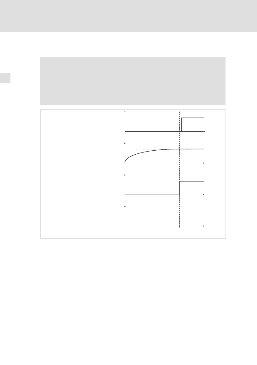
4
t [s]
HIGH(1)
LOW(0)
ECSx : X6/SI1ü
t [s]
100%
0%
t [s]
HIGH(1)
LOW(0)
ECSxK: X26 (24 V DC)
t [s]
HIGH(1)
LOW(0)
K1
U
ZK
1
Installation électrique
Câblage
Fonctionnement avec un autre module d’alimentation
4.4.2 Fonctionnement avec un autre module d’alimentation
Stop !
ƒ
Le shuntage du régulateur du courant de charge ne peut avoir
lieu qu’au bout d’1 seconde au moins après la mise sous tension
(X26 = HAUT).
ƒ
Ne débloquer le variateur (X6/SI1 = HAUT) que si le régulateur du
courant de charge est shunté.
86
Fig.4-3 Graphiques de fonctionnement avec un autre module d’alimentation
ECSx
U
ECSxK Module condensateur de la série ECS
K1 Contacteur réseau
Module d’axe de la série ECS
Tension du bus CC
ZK
ECSXK011
EDKCSEK002 DE/EN/FR 2.0
Page 87

5 Vérification de l’installation
Une fois l’installation terminée, vérifier ...
ƒ
le câblage dans son intégralité pour éviter un court-circuit ou un défaut de
mise à la terre ;
ƒ
le raccordement de puissance (X23) :
–
polarité de l’alimentation de la tension du bus CC via les bornes +UG,
-UG ;
ƒ
le raccordement de commande (X26) :
–
shuntage du régulateur du courant de charge en fonction du module
d’alimentation raccordé.
Remarque importante !
La prochaine étape est la mise en service du système
d’entraînement.
Pour plus d’informations à ce sujet, se reporter à la documentation
des modules d’alimentation et des modules d’axe raccordés.
Vérification de l’installation 5
EDKCSEK002 DE/EN/FR 2.0
87
Page 88

© 08/2010
Lenze Automation GmbH
Hans-Lenze-Str. 1
D-31855 Aerzen
Germany
+49 (0)51 54 / 82-0
+49 (0)51 54 / 82 - 28 00
Lenze@Lenze.de
www.Lenze.com
Service Lenze Service GmbH
Breslauer Straße 3
D-32699 Extertal
Germany
00 80 00 / 24 4 68 77 (24 h helpline)
+49 (0)51 54 / 82-11 12
Service@Lenze.de
EDKCSEK002.CkaDE/EN/FR2.0TD29
10 9 8 7 6 5 4 3 2 1
 Loading...