

Page 1

EDKCSDK002
.ðwU
Ä.ðwUä
Montageanleitung
Mounting Instructions
Instructions de montage
ECS
ECSDKxxx
Kondensatormodul "Durchstoß−Technik"
Capacitor module in push−through design
Module condensateur en montage traversant
Page 2

Lesen Sie zuerst diese Anleitung, bevor Sie mit den Arbeiten beginnen!
Beachten Sie die enthaltenen Sicherheitshinweise.
Please read these Instructions before you start working!
Follow the enclosed safety instructions.
Veuillez lire attentivement cette documentation avant toute action !
Les consignes de sécurité doivent impérativement être respectées.
Page 3

ECSDK_001A
Page 4

Lieferumfang
Position Beschreibung Anzahl
Kondensatormodul ECSDKxxx 1
Beipack mit Befestigungsmaterial 1
Montageanleitung 1
Bohrschablone 1
Hinweis!
Die Steckverbinder ECSZK000X0B müssen gesondert bezogen werden.
Anschlüsse und Schnittstellen
Position Beschreibung ausführliche
X23 Anschlüsse
l Zwischenkreisspannung
l PE
X26 Steueranschluss
l Überbrückung der Ladestrombegrenzung
Informationen
25
28
4
EDKCSDK002 DE/EN/FR 1.1
Page 5
Diese Anleitung ist gültig für Kondensatormodule ECSDKxxx ab dem Gerätestand:
ECS D K xxx X 4 B xxx 1A
Gerätetyp
Bauform
E = Einbaugerät IP20
D = Durchstoßtechnik (thermische Separierung)
C = Cold−Plate−Technik
Kapazität
001 = 705 mF (±20 %)
002 = 1410 mF (±20 %)
Spannungsklasse
4 = 400 V/480 V
Technische Ausführung
B = Standard
Variante
Stand Hardware
1A oder höher
EDKCSDK002 DE/EN/FR 1.1
5
Page 6

Tipp!
Aktuelle Dokumentationen und Software−Updates zu Lenze Produkten finden Sie
im Internet jeweils im Bereich "Downloads" unter
http://www.Lenze.com
© 2005 Lenze Drive Systems GmbH, Hans−Lenze−Straße 1, D−31855 Aerzen
Ohne besondere schriftliche Genehmigung von Lenze Drive Systems GmbH darf kein Teil dieser Dokumentation vervielfältigt oder Dritten zugänglich gemacht werden.
Wir haben alle Angaben in dieser Dokumentation mit größter Sorgfalt zusammengestellt und auf Übereinstimmung
mit der beschriebenen Hard− und Software geprüft. Trotzdem können wir Abweichungen nicht ganz ausschließen. Wir
übernehmen keine juristische Verantwortung oder Haftung für Schäden, die dadurch eventuell entstehen. Notwendige Korrekturen werden wir in die nachfolgenden Auflagen einarbeiten.
6
EDKCSDK002 DE/EN/FR 1.1
Page 7

Inhalt i
1 Sicherheitshinweise 8 . . . . . . . . . . . . . . . . . . . . . . . . . . . . . . . . . . . . . . . . . . . . . . . .
1.1 Allgemeine Sicherheits− und Anwendungshinweise für
Lenze−Kondensatormodule 8 . . . . . . . . . . . . . . . . . . . . . . . . . . . . . . . . . . . .
1.2 Restgefahren 11 . . . . . . . . . . . . . . . . . . . . . . . . . . . . . . . . . . . . . . . . . . . . . . .
1.3 Sicherheitshinweise für die Installation nach UL oder UR 12 . . . . . . . . . . .
1.4 Definition der verwendeten Hinweise 13 . . . . . . . . . . . . . . . . . . . . . . . . . . .
2 Technische Daten 15 . . . . . . . . . . . . . . . . . . . . . . . . . . . . . . . . . . . . . . . . . . . . . . . . . .
2.1 Allgemeine Daten / Einsatzbedingungen 15 . . . . . . . . . . . . . . . . . . . . . . . .
2.2 Bemessungsdaten 16 . . . . . . . . . . . . . . . . . . . . . . . . . . . . . . . . . . . . . . . . . . .
3 Mechanische Installation 17 . . . . . . . . . . . . . . . . . . . . . . . . . . . . . . . . . . . . . . . . . . . .
3.1 Wichtige Hinweise 17 . . . . . . . . . . . . . . . . . . . . . . . . . . . . . . . . . . . . . . . . . . .
3.2 Montage mit thermischer Separierung (Durchstoß−Technik) 18 . . . . . . . . .
3.2.1 Abmessungen 19 . . . . . . . . . . . . . . . . . . . . . . . . . . . . . . . . . . . . .
3.2.2 Montageschritte 21 . . . . . . . . . . . . . . . . . . . . . . . . . . . . . . . . . . .
4 Elektrische Installation 22 . . . . . . . . . . . . . . . . . . . . . . . . . . . . . . . . . . . . . . . . . . . . . .
4.1 EMV−gerechte Verdrahtung
(Aufbau des CE−typischen Antriebssystems) 22 . . . . . . . . . . . . . . . . . . . . . .
4.2 Leistungsanschlüsse 25 . . . . . . . . . . . . . . . . . . . . . . . . . . . . . . . . . . . . . . . . .
4.2.1 Anschluss an den DC−Zwischenkreis (+UG, −UG) 27 . . . . . . . . . .
4.3 Steueranschluss X26 28 . . . . . . . . . . . . . . . . . . . . . . . . . . . . . . . . . . . . . . . . .
4.4 Verdrahtung 29 . . . . . . . . . . . . . . . . . . . . . . . . . . . . . . . . . . . . . . . . . . . . . . . .
4.4.1 Betrieb mit Versorgungsmodul ECSxE 29 . . . . . . . . . . . . . . . . . .
4.4.2 Betrieb mit anderem Versorger 31 . . . . . . . . . . . . . . . . . . . . . . .
5 Installation überprüfen 32 . . . . . . . . . . . . . . . . . . . . . . . . . . . . . . . . . . . . . . . . . . . . .
EDKCSDK002 DE/EN/FR 1.1
7
Page 8

1
Sicherheitshinweise
Allgemeine Sicherheits− und Anwendungshinweise
1 Sicherheitshinweise
1.1 Allgemeine Sicherheits− und Anwendungshinweise für
Lenze−Kondensatormodule
(gemäß Niederspannungsrichtlinie 73/23/EWG)
Allgemein
Lenze−Kondensatormodule können während des Betriebs − ihrer Schutzart entsprechend − spannungsführende Teile haben. Oberflächen können heiß sein.
Bei unzulässigem Entfernen der erforderlichen Abdeckung, bei unsachgemäßem
Einsatz, bei falscher Installation oder Bedienung besteht die Gefahr von schweren
Personen− oder Sachschäden.
Weitere Informationen entnehmen Sie der Dokumentation.
Alle Arbeiten zum Transport, zur Installation, zur Inbetriebnahme und zur Instand-
haltung darf nur qualifiziertes Fachpersonal ausführen (IE 364 bzw. CENELEC HD 384 oder DIN VDE 0100 und IEC−Report 664 oder DIN VDE 0110 und nationale Unfallverhütungsvorschriften beachten).
Qualifiziertes Fachpersonal im Sinne dieser grundsätzlichen Sicherheitshinweise
sind Personen, die mit Aufstellung, Montage, Inbetriebsetzung und Betrieb des
Produkts vertraut sind und die über die ihrer Tätigkeit entsprechenden Qualifikationen verfügen.
8
EDKCSDK002 DE/EN/FR 1.1
Page 9

Sicherheitshinweise
Allgemeine Sicherheits− und Anwendungshinweise
Bestimmungsgemäße Verwendung
Kondensatormodule sind Komponenten, die zum Einbau in elektrische Anlagen
oder Maschinen bestimmt sind. Sie sind keine Haushaltsgeräte, sondern als Komponenten ausschließlich für die Verwendung zur gewerblichen Nutzung bzw. professionellen Nutzung im Sinne der EN 61000−3−2 bestimmt. Die Dokumentation
enthält Hinweise zur Einhaltung der Grenzwerte nach EN 61000−3−2.
Bei Einbau der Kondensatormodule in Maschinen ist die Inbetriebnahme (d. h. die
Aufnahme des bestimmungsgemäßen Betriebs) solange untersagt, bis festgestellt wurde, dass die Maschine den Bestimmungen der EG−Richtlinie 98/37/EG
(Maschinenrichtlinie) entspricht; EN 60204 beachten.
Die Inbetriebnahme (d. h. die Aufnahme des bestimmungsgemäßen Betriebs) ist
nur bei Einhaltung der EMV−Richtlinie (89/336/EWG) erlaubt.
Die Kondensatormodule erfüllen die Anforderungen der Niederspannungsrichtlinie 73/23/EWG. Die harmonisierten Normen der Reihe EN 50178 / DIN VDE 0160
werden für die Kondensatormodule angewendet.
Die technischen Daten und die Angaben zu Anschlussbedingungen entnehmen Sie
dem Leistungsschild und der Dokumentation. Halten Sie diese unbedingt ein.
Warnung: Die Kondensatormodule sind Produkte mit eingeschränkter Erhältlichkeit nach EN 61800−3. Diese Produkte können im Wohnbereich Funkstörungen verursachen. In diesem Fall kann es für den Betreiber erforderlich sein, entsprechende
Maßnahmen durchzuführen.
Transport, Einlagerung
Beachten Sie die Hinweise für Transport, Lagerung und sachgemäße Handhabung.
Halten Sie die klimatischen Bedingungen nach EN 50178 ein.
Aufstellung
Sie müssen die Kondensatormodule nach den Vorschriften der zugehörigen Dokumentation aufstellen und kühlen.
Sorgen Sie für sorgfältige Handhabung und vermeiden Sie mechanische Überlastung. Verbiegen Sie bei Transport und Handhabung weder Bauelemente noch ändern Sie Isolationsabstände. Berühren Sie keine elektronischen Bauelemente und
Kontakte.
Kondensatormodule enthalten elektrostatisch gefährdete Bauelemente, die Sie
durch unsachgemäße Handhabung leicht beschädigen können. Beschädigen oder
zerstören Sie keine elektrischen Komponenten, da Sie dadurch Ihre Gesundheit gefährden können!
1
EDKCSDK002 DE/EN/FR 1.1
9
Page 10

1
Sicherheitshinweise
Allgemeine Sicherheits− und Anwendungshinweise
Elektrischer Anschluss
Beachten Sie bei Arbeiten an unter Spannung stehenden Kondensatormodulen die
geltenden nationalen Unfallverhütungsvorschriften (z. B. VBG 4).
Führen Sie die elektrische Installation nach den einschlägigen Vorschriften durch
(z. B. Leitungsquerschnitte, Absicherungen, Schutzleiteranbindung). Zusätzliche
Hinweise enthält die Dokumentation.
Die Dokumentation enthält Hinweise für die EMV−gerechte Installation (Schirmung, Erdung, Anordnung von Filtern und Verlegung der Leitungen). Beachten Sie
diese Hinweise ebenso bei CE−gekennzeichneten Kondensatormodulen. Der Hersteller der Anlage oder Maschine ist verantwortlich für die Einhaltung der durch die
EMV−Gesetzgebung geforderten Grenzwerte.
Betrieb
Sie müssen Anlagen mit eingebauten Kondensatormodulen ggf. mit zusätzlichen
Überwachungs− und Schutzeinrichtungen gemäß den jeweils gültigen Sicherheitsbestimmungen ausrüsten (z. B. Gesetz über technische Arbeitsmittel, Unfallverhütungsvorschriften). Sie dürfen die Kondensatormodule an Ihre Anwendung anpassen. Beachten Sie dazu die Hinweise in der Dokumentation.
Nachdem das Kondensatormodul von der Versorgungsspannung getrennt ist, dürfen Sie spannungsführende Geräteteile und Leistungsanschlüsse nicht sofort berühren, weil Kondensatoren aufgeladen sein können. Beachten Sie dazu die entsprechenden Hinweisschilder auf dem Kondensatormodul.
Halten Sie während des Betriebs alle Schutzabdeckungen und Türen geschlossen.
Hinweis für UL−approbierte Anlagen mit eingebauten Kondensatormodulen:
UL warnings sind Hinweise, die nur für UL−Anlagen gelten. Die Dokumentation
enthält spezielle Hinweise zu UL.
Wartung und Instandhaltung
Die Kondensatormodule sind wartungsfrei, wenn die vorgeschriebenen Einsatzbedingungen eingehalten werden.
Bei verunreinigter Umgebungsluft können die Kühlflächen des Kondensatormoduls verschmutzen oder Kühlöffnungen verstopft werden. Bei diesen Betriebsbedingungen deshalb regelmäßig die Kühlflächen und Kühlöffnungen reinigen. Dazu
niemals scharfe oder spitze Gegenstände verwenden!
Entsorgung
Metalle und Kunststoffe zur Wiederverwertung geben. Bestückte Leiterplatten
fachgerecht entsorgen.
Beachten Sie unbedingt die produktspezifischen Sicherheits− und
Anwendungshinweise in dieser Anleitung!
10
EDKCSDK002 DE/EN/FR 1.1
Page 11

1.2 Restgefahren
Personenschutz
ƒ Überprüfen Sie vor Arbeiten am Kondensatormodul, ob alle
Leistungsklemmen spannungslos sind, denn
– nach dem Abschalten der Netzspannung am Versorgungsmodul führen die
Leistungsklemmen +UG und −UG noch mindestens 3 Minuten gefährliche
Spannung.
– bei gestopptem Motor führen die Leistungsklemmen +UG und −UG
gefährliche Spannung.
ƒ Im Fehlerfall (Körper− oder Erdschluss) kann ein Fehler−Gleichstrom im
Schutzleiter verursacht werden. Wird für den Schutz im Falle einer direkten
oder indirekten Berührung ein Fehlerstrom−Schutzschalter
(Differenzstromgerät) verwendet, ist auf der Stromversorgungsseite nur ein
Fehlerstrom−Schutzschalter vom Typ B zulässig. Anderenfalls muss eine
andere Schutzmaßnahme angewendet werden, wie z. B. Trennung von der
Umgebung durch doppelte oder verstärkte Isolierung oder Trennung vom
Versorgungsnetz durch einen Transformator.
Geräteschutz
ƒ Alle steckbaren Anschlussklemmen nur im spannungslosen Zustand
aufstecken oder abziehen.
ƒ Die Leistungsklemmen +UG, −UG und PE sind nicht verpolungssicher
ausgelegt.
– Polarität der Leistungsklemmen beim Verdrahten beachten.
ƒ Erst wenn das Versorgungsmodul im Leistungsverbund betriebsbereit ist und
die Ladestrombegrenzung überbrückt ist, darf Leistung umgewandelt
werden. Sonst kann die Ladestrombegrenzung zerstört werden.
ƒ Bei aktiver Ladestrombegrenzung kann zyklisches Ein− und Ausschalten der
Netzspannung am Versorgungsmodul das Kondensatormodul überlasten und
zerstören. Deshalb müssen bei zyklischem Netzschalten über einen längeren
Zeitraum zwischen zwei Einschaltvorgängen mindestens 3 Minuten
vergehen.
Sicherheitshinweise
Restgefahren
1
EDKCSDK002 DE/EN/FR 1.1
11
Page 12

1
Sicherheitshinweise
Sicherheitshinweise für die Installation nach UL oder UR
1.3 Sicherheitshinweise für die Installation nach UL oder U
Warnings!
General markings:
ƒ Use 60/75 °C or 75 °C copper wire only.
ƒ Maximum ambient temperature 55 °C, with reduced output current.
Terminal tightening torque of lb−in (Nm)
ƒ X 23
– 10.6 ... 13.3 lb−in (1.2 ... 1.5 Nm)
ƒ X 26
– 4.4 ... 7.1 lb−in (0.5 ... 0.8 Nm)
Wiring diagram AWG
ƒ X 23
– AWG 12 ... AWG 8
ƒ X 26
– AWG 24 ... AWG 12
R
12
EDKCSDK002 DE/EN/FR 1.1
Page 13

Definition der verwendeten Hinweise
1.4 Definition der verwendeten Hinweise
Um auf Gefahren und wichtige Informationen hinzuweisen, werden in dieser Dokumentation folgende Signalwörter und Symbole verwendet:
Sicherheitshinweise
Aufbau der Sicherheitshinweise:
Gefahr!
(kennzeichnet die Art und die Schwere der Gefahr)
Hinweistext
(beschreibt die Gefahr und gibt Hinweise, wie sie vermieden werden
kann)
Piktogramm und Signalwort Bedeutung
Gefahr von Personenschäden durch gefährliche elektrische Spannung
Gefahr!
Gefahr!
Stop!
Anwendungshinweise
Hinweis auf eine unmittelbar drohende Gefahr, die den
Tod oder schwere Verletzungen zur Folge haben kann,
wenn nicht die entsprechenden Maßnahmen getroffen
werden.
Gefahr von Personenschäden durch eine allgemeine Gefahrenquelle
Hinweis auf eine unmittelbar drohende Gefahr, die den
Tod oder schwere Verletzungen zur Folge haben kann,
wenn nicht die entsprechenden Maßnahmen getroffen
werden.
Gefahr von Sachschäden
Hinweis auf eine mögliche Gefahr, die Sachschäden zur
Folge haben kann, wenn nicht die entsprechenden Maßnahmen getroffen werden.
Sicherheitshinweise
1
Piktogramm und Signalwort Bedeutung
Hinweis!
Tipp!
EDKCSDK002 DE/EN/FR 1.1
Wichtiger Hinweis für die störungsfreie Funktion
Nützlicher Tipp für die einfache Handhabung
Verweis auf andere Dokumentation
13
Page 14

1
Sicherheitshinweise
Definition der verwendeten Hinweise
Spezielle Sicherheitshinweise und Anwendungshinweise für UL und UR
Piktogramm und Signalwort Bedeutung
Sicherheitshinweis oder Anwendungshinweis für den
Betrieb eines UL−approbierten Geräts in UL−approbierten
Warnings!
Warnings!
Anlagen.
Möglicherweise wird das Antriebssystem nicht UL−gerecht betrieben, wenn nicht die entsprechenden Maßnahmen getroffen werden.
Sicherheitshinweis oder Anwendungshinweis für den
Betrieb eines UR−approbierten Geräts in UL−approbierten
Anlagen.
Möglicherweise wird das Antriebssystem nicht UL−gerecht betrieben, wenn nicht die entsprechenden Maßnahmen getroffen werden.
14
EDKCSDK002 DE/EN/FR 1.1
Page 15

Technische Daten
Allgemeine Daten / Einsatzbedingungen
2 Technische Daten
2.1 Allgemeine Daten / Einsatzbedingungen
Normen und Einsatzbedingungen
Konformität CE
Approbationen
Rüttelfestigkeit Beschleunigungsfest bis 0.7 g (Germanischer Lloyd, allgemeine Bedingun-
Klimatische Bedingungen Klasse 3K3 nach EN 50178 (ohne Betauung, relative Feuchte 30 ... 95 %)
Verschmutzungsgrad VDE 0110 Teil 2 Verschmutzungsgrad 2
Verpackung (DIN 4180) Versandverpackung
Zulässige Tempe-
raturbereiche
Zulässige Aufstellungshöhe 0 ... 4000 m üNN Bei über 1000 m üNN AC−Bemessungsstrom um
Einbau Einbau in Schaltschrank
Einbaulage senkrecht hängend
Einbaufreiräume
Transport −25 ... +70 °C
Lagerung −25 ... +55 °C
Betrieb 0 ... +55 °C Bei über +40 °C AC−Bemessungsstrom um 2 %/°C re-
oberhalb ³ 65 mm
unterhalb ³ 65 mm
seitlich ohne Abstand anreihbar
UL 508C Power Conversion Equipment
gen)
mit Schirmbefestigungs−Set ECSZS000B0B001: > 195 mm
Niederspannungsrichtlinie (73/23/EWG)
Underwriter Laboratories (File No. E132659)
für USA und Kanada
duzieren.
5 %/1000 m reduzieren.
2
EDKCSDK002 DE/EN/FR 1.1
15
Page 16

2
Technische Daten
Bemessungsdaten
Allgemeine elektrische Daten
EMV Einhaltung der Anforderungen nach EN 61800−3
Störaussendung Einhaltung der Grenzwertklasse A nach EN 55011
Störfestigkeit
Isolationsfestigkeit Überspannungskategorie III nach VDE 0110
Ableitstrom gegen PE (nach EN 50178) > 3.5 mA AC bei Betrieb mit entsprechenden Antriebsreglern
Schutzart l IP20 bei Standardmontage
Schutzisolierung von Steuerschaltkreisen Sichere Trennung vom Netz: Doppelte/verstärkte Isolierung nach
1)
Die Störfestigkeit in den genannten Schärfegraden muss durch den Schaltschrank
gewährleistet sein! Der Anwender muss die Einhaltung der genannten Schärfegrade
prüfen!
(erreicht mit anwendungstypischem Summenfilter)
Anforderungen nach EN 61800−3
Anforderung Norm Schärfegrade
1)
ESD
leitungsgeführte Hochfrequenz
HF−Einstrahlung (Gehäuse)
Burst EN 61000−4−4 3/4, d. h. 2 kV/5 kHz
Surge (Stoßspannung auf
Netzleitung)
l IP20 bei Montage in Cold−Plate−Technik
l IP20 bei Montage mit thermischer Separierung, IP54 auf der Kühl-
körperseite
EN 50178;
Bemessungs−Isolationsspannung 300 V x √2
EN 61000−4−2 3, d. h.
EN 61000−4−6 10 V; 0.15 ... 80 MHz
EN 61000−4−3 3, d. h. 10 V/m;
EN 61000−4−5 3, d. h. 1.2/50 ms
l 8 kV bei Luftentladung
l 6 kV bei Kontaktentla-
dung
80 ... 1000 MHz
l 1 kV Phase−Phase
l 2 kV Phase−PE
2.2 Bemessungsdaten
Die wichtigsten Bemessungsdaten finden Sie auf dem Typenschild des
Gerätes. Weitere Daten finden Sie in der ausführlichen
Dokumentation.
16
EDKCSDK002 DE/EN/FR 1.1
Page 17

3 Mechanische Installation
3.1 Wichtige Hinweise
ƒ Kondensatormodule der Reihe ECS verfügen über die Schutzart IP20 und sind
daher nur für den Einbau in Schaltschränken bestimmt.
ƒ Bei verunreinigter Kühlluft (Staub, Flusen, Fette, aggressive Gase):
– Ausreichende Gegenmaßnahmen treffen, z. B. separate Luftführung,
Einbau von Filtern, regelmäßige Reinigung.
ƒ Mögliche Einbaulagen:
– Senkrecht an der Montageplatte
– Zwischenkreisanschlüsse (X23) oben
– Anschluss zur Überbrückung der Ladestrombegrenzung (X26) unten
ƒ Halten Sie die angegebenen Einbaufreiräume oberhalb und unterhalb zu
anderen Installationen ein!
– Bei Verwendung des Schirmbefestigungs−Set ECSZS000X0B001 ist ein
zusätzlicher Freiraum erforderlich.
– Achten Sie auf ungehinderten Zutritt der Kühlluft und ungehinderten
Austritt der Abluft.
– Sie können mehrere Module der Reihe ECS im Schaltschrank ohne
Zwischenraum nebeneinander befestigen.
ƒ Die Montageplatte des Schaltschranks muss elektrisch leitfähig sein.
ƒ Bei dauerhaften Schwingungen oder Erschütterungen den Einsatz von
Schwingungsdämpfern prüfen.
Mechanische Installation
Wichtige Hinweise
3
EDKCSDK002 DE/EN/FR 1.1
17
Page 18

3
3.2 Montage mit thermischer Separierung (Durchstoß−Technik)
Mechanische Installation
Montage mit thermischer Separierung (Durchstoß−Technik)
Bei Durchstoß−Technik muss die Rückwand des Schaltschranks eine mindestens
3 mm starke Stahlplatte sein.
Die Kanten des Einbauausschnitts und der Befestigungsbohrungen für die Klemmbügel müssen leicht nach innen (zum Kondensatormodul) gewölbt sein.
Kühlung
Mit dem separierten Kühlkörper reduzieren Sie die Wärmeentwicklung im Schaltschrank.
ƒ Aufteilung der Verlustleistung:
– ca. 65 % über separarierten Kühler
– ca. 35 % im Innenraum des Kondensatormoduls
ƒ Schutzklasse des separierten Kühlers: IP54
– Die Dichtfläche des Kondensatormoduls am Kühlkörper muss vollständig
an der Montageplatte aufliegen.
– Schrauben für Klemmbügel mit flüssiger Gewindedichtung (z. B.
Loctite 620) verkleben.
ƒ Für die ausreichende Kühlung des Antriebssystems:
– Luftstrom hinter der Rückwand des Schaltschranks ³ 3 m/s (z. B. durch
Verwendung eines Summenlüfters).
ƒ Bei ausreichender Kühlung gelten weiterhin die Bemessungsdaten der
Kondensatormodule.
18
EDKCSDK002 DE/EN/FR 1.1
Page 19

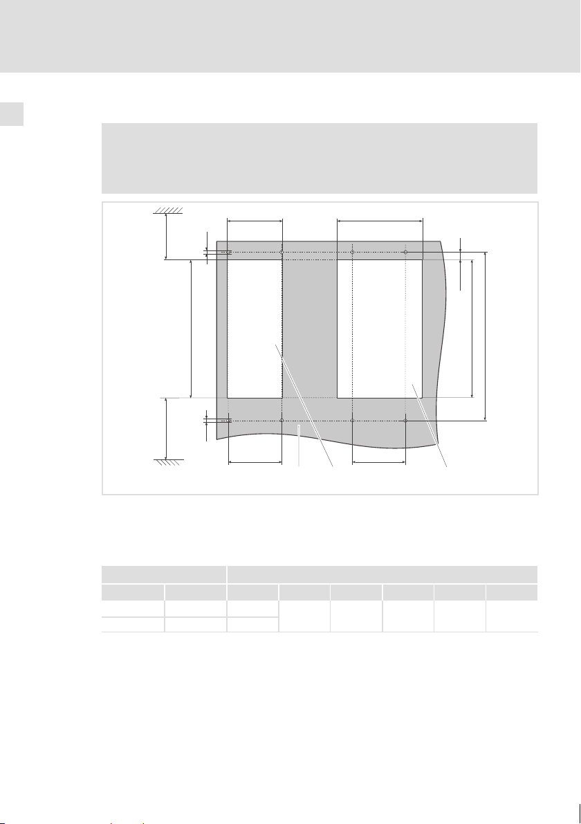
Montage mit thermischer Separierung (Durchstoß−Technik)
3.2.1 Abmessungen
Hinweis!
Mit Schirmbefestigungs−Set ECSZS000X0B001:
ƒ Einbaufreiraum unterhalb des Moduls > 195 mm
Mechanische Installation
Abmessungen
3
0
Z Z
a1
³ 65 mm
³ 65 mm
Abb. 3−1 Abmessungen bei Bauform "Durchstoß−Technik"
Kondensatormodul Maße [mm]
Typ Bau-
ECSDK001 88,5 78,5
ECSDK002 131 121,5
ee1
Z Einbauausschnitt (a1 x b1), 20
a a1 b b1 c1 d e e1 g h
größe
g
h
b1
b
g
c1
a
240 197 75 250 109 67 M5 10,5
1
a1
g
h
d
b1
b
c1
a
d
g
ECSXK007
EDKCSDK002 DE/EN/FR 1.1
19
Page 20
3
Mechanische Installation
Montage mit thermischer Separierung (Durchstoß−Technik)
Abmessungen
Abmessungen Einbauausschnitt
Hinweis!
Mit Schirmbefestigungs−Set ECSZS000X0B001:
ƒ Einbaufreiraum unterhalb des Einbauausschnitts > 220 mm
a1 a1
g
³ 60 mm
h
b1
³ 90 mm
Abb. 3−2 Abmessungen Einbauausschnitt
Einbauausschnitt für Baugröße
Einbauausschnitt für Baugröße
Montageplatte
Kondensatormodul Maße [mm]
Typ Baugröße a1 b1 c1 d g h
ECSDK001 78,5
ECSDK002 121,5
g
c1
0
1
197 75 250 M5 10,5
c1
2
b1
d
ECSXA063
20
EDKCSDK002 DE/EN/FR 1.1
Page 21

Montage mit thermischer Separierung (Durchstoß−Technik)
3.2.2 Montageschritte
So montieren Sie das Kondensatormodul:
1. Befestigungsbohrungen für die Klemmbügel auf Montagefläche vorbereiten.
– Dazu Bohrschablone anlegen.
2. Einbauausschnitt vorbereiten.
– Die Kanten des Einbauausschnitts und der Befestigungsbohrungen für die
Klemmbügel müssen leicht nach innen (zum Kondensatormodul) gewölbt
sein.
3. Klemmbügel befestigen.
– Schrauben für Klemmbügel mit flüssiger Gewindedichtung (z. B.
Loctite 620) verkleben.
4. Kondensatormodul in den Einbauausschnitt schieben.
5. Kondensatormodul in Klemmbügel oben und unten einrasten.
Mechanische Installation
Montageschritte
3
EDKCSDK002 DE/EN/FR 1.1
21
Page 22

4
Elektrische Installation
EMV−gerechte Verdrahtung (Aufbau des CE−typischen Antriebssystems)
4 Elektrische Installation
4.1 EMV−gerechte Verdrahtung (Aufbau des CE−typischen Antriebssystems)
Allgemeine Hinweise
ƒ Die elektromagnetische Verträglichkeit einer Maschine ist abhängig von der
Art und Sorgfalt der Installation. Beachten Sie besonders:
– Aufbau
– Filterung
– Schirmung
– Erdung
ƒ Bei abweichender Installation ist für die Bewertung der Konformität zur
EMV−Richtlinie die Überprüfung der Maschine oder Anlage auf Einhaltung
der EMV−Grenzwerte erforderlich. Dies gilt z. B. bei:
– Verwendung ungeschirmter Leitungen
– Verwendung von Sammel−Entstörfiltern anstelle der zugeordneten
Funk−Entstörfilter
– Betrieb ohne Funk−Entstörfilter
ƒ Die Verantwortung für die Einhaltung der EMV−Richtlinie in der
Maschinenanwendung liegt beim Weiterverwender.
– Wenn Sie die folgenden Maßnahmen beachten, können Sie davon
ausgehen, dass beim Betrieb der Maschine keine vom Antriebssystem
verursachten EMV−Probleme auftreten und die EMV−Richtlinie bzw. das
EMV−Gesetz erfüllt ist.
– Werden in der Nähe der Achsmodule Geräte betrieben, die der
CE−Anforderung hinsichtlich der Störfestigkeit EN 61000−6−2 nicht
genügen, können diese Geräte durch die Achsmodule elektromagnetisch
beeinträchtigt werden.
22
EDKCSDK002 DE/EN/FR 1.1
Page 23

Elektrische Installation
EMV−gerechte Verdrahtung (Aufbau des CE−typischen Antriebssystems)
Aufbau
ƒ Versorgungsmodule, Kondensatormodule (optional), Achsmodule,
Funk−Entstörfilter und Netzdrossel großflächig mit geerdeter Montageplatte
verbinden:
– Montageplatten mit elektrisch leitender Oberfläche (verzinkt oder
rostfreier Stahl) erlauben eine dauerhafte Verbindung.
– Lackierte Platten sind nicht geeignet für die EMV−gerechte Installation.
ƒ Verwendung des Kondensatormoduls ECSxK...:
– Installieren Sie das Kondensatormodul zwischen dem Versorgungsmodul
und dem/den Achsmodul(en).
– Ist die Gesamtleitungslänge im Zwischenkreisverbund > 5 m, installieren
Sie das Kondensatormodul möglichst nah am Achsmodul mit der größten
Leistung.
ƒ Verwendung mehrerer Montageplatten:
– Montageplatten großflächig leitend miteinander verbinden (z. B. mit
Kupferbändern).
ƒ Beim Verlegen der Leitungen auf räumliche Trennung der Motorleitung von
Signal− und Netzleitungen achten.
ƒ Eine gemeinsame Klemmenleiste für Netzeingang und Motorausgang
vermeiden.
ƒ Leitungsführung möglichst dicht am Bezugspotenzial. Frei schwebende
Leitungen wirken wie Antennen.
Filterung
Verwenden Sie nur die den Versorgungssmodulen zugeordneten Funk−Entstörfilter und Netzdrosseln:
ƒ Funk−Entstörfilter reduzieren unzulässige hochfrequente Störgrößen auf ein
zulässiges Maß.
ƒ Netzdrosseln reduzieren niederfrequente Störgrößen, die insbesondere
durch die Motorleitungen bedingt werden und von deren Länge abhängig
sind.
4
EDKCSDK002 DE/EN/FR 1.1
23
Page 24

4
Elektrische Installation
EMV−gerechte Verdrahtung (Aufbau des CE−typischen Antriebssystems)
Schirmung
ƒ Am Achsmodul den Schirm der Motorleitung
– mit dem Schirmbefestigungs−Set ECSZS000X0B001 auflegen.
– großflächig mit der Montageplatte unterhalb des Achsmoduls verbinden.
– Empfehlung: Schirm mit Erdungsschellen auf metallisch blanken
Montageflächen ausführen.
ƒ Bei Schützen, Motorschutzschalter oder Klemmen in der Motorleitung:
– Die Schirme der dort angeschlossenen Leitungen miteinander verbinden
und ebenfalls großflächig mit der Montageplatte kontaktieren.
ƒ Im Klemmenkasten des Motors oder am Motorgehäuse den Schirm
großflächig mit PE verbinden:
– Metallische Kabelverschraubungen am Motorklemmkasten gewährleisten
eine großflächige Verbindung des Schirms mit dem Motorgehäuse.
ƒ Die Steuerleitungen abschirmen:
– Schirme digitaler Steuerleitungen beidseitig auflegen.
– Schirme analoger Steuerleitungen einseitig auflegen.
– Schirme auf kürzestem Weg mit den Schirmanschlüssen am Achsmodul
verbinden.
ƒ Einsatz der Achsmodule in Wohngebieten:
– Zur Begrenzung der Störstrahlung zusätzliche Schirmdämpfung ≥10 dB
vorsehen. Diese wird in der Regel durch Einbau in handelsübliche,
geschlossene, metallische und geerdete Schaltschränke oder −kästen
erreicht.
Erdung
ƒ Alle metallisch leitfähigen Komponenten (z. B. Versorgungsmodul,
Kondensatormodul, Achsmodul, Funk−Entstörfilter, Motorfilter,
Netzdrosseln) durch entsprechende Leitungen von einem zentralen
Erdungspunkt (PE−Schiene) erden.
ƒ Die in den Sicherheitsvorschriften definierten Mindestquerschnitte
einhalten:
– Für die EMV ist nicht der Leitungsquerschnitt, sondern die Oberfläche der
Leitung und der flächigen Kontaktierung entscheidend.
24
EDKCSDK002 DE/EN/FR 1.1
Page 25

4.2 Leistungsanschlüsse
Stop!
ƒ Das Kondensatormodul ist ausschließlich für den Betrieb an
symmetrischen Netzen zugelassen. Ein Betrieb an
Außenleiter−geerdeten Netzen ist nicht zulässig.
ƒ Beachten Sie die maximal zulässige Netzspannung. Eine höhere
Spannung zerstört das Kondensatormodul.
ƒ Der Ableitstrom gegen Erde (PE) ist > 3.5 mA AC bzw. > 10 mA DC.
Nach EN 50178 ist eine Festinstallation erforderlich. Der
PE−Anschluss muss nach EN 50178 ausgeführt sein.
ƒ Alle Leistungsanschlüsse sind steckbar ausgeführt und kodiert. Die
Steckverbinder sind im Zubehör−Set Kondensatormodule ECSZK000X0B
enthalten. Dieses muss gesondert bezogen werden.
ƒ Installation der Leitungen nach EN 60204−1.
ƒ Die verwendeten Leitungen müssen den geforderten Approbationen am
Einsatzort entsprechen (z. B. VDE, UL usw.).
Klemmenbelegung
Klemme Funktion Elektrische Daten
X23 Anschluss Zwischenkreisspannung
X23/+UG
X23/+UG
X23/−UG
X23/−UG
X23/PE
X23/PE
Leitungsquerschnitte und Schraubenanzugsmomente
positive Einspeisung Zwischenkreisspannung
negative Einspeisung Zwischenkreisspannung
Anschluss Erde
Elektrische Installation
Leistungsanschlüsse
anwendungs− und typabhängig
0 ... 770 V
bis 24,5 A (
16)
4
Leitungstyp Aderendhülse mögliche Leitungs-
Klemmenleiste X23
starr
flexibel
EDKCSDK002 DE/EN/FR 1.1
−
ohne Aderendhülse
mit Aderendhülse
mit TWIN−Aderendhülse
querschnitte
0,2 ... 10 mm
(AWG 24 ... 8)
0,2 ... 10 mm
(AWG 24 ... 8)
0,25 ... 6 mm
(AWG 22 ... 10)
0,25 ... 4 mm
(AWG 22 ... 12)
Anzugsmoment Abisolierlänge
2
2
2
2
1,2 ... 1,5 Nm
(10.6 ... 13.3 lb−in)
5 mm
25
Page 26

4
Elektrische Installation
Leistungsanschlüsse
Geschirmte Leitungen
Folgende Faktoren bestimmen maßgeblich die Wirkung der geschirmten Leitungen:
ƒ Gute Schirmanbindung
– Schirm großflächig auflegen
ƒ Niedriger Schirmwiderstand
– Nur Schirme mit verzinntem oder vernickeltem Kupfergeflecht verwenden
(Schirme aus Stahlgeflecht sind ungeeignet).
ƒ Hoher Überdeckungsgrad des Schirmgeflechts
– Mindestens 70 ... 80 % mit 90° Überdeckungswinkel
Schirmschellen enthält das Schirmbefestigungs−Set ECSZS000X0B001.
26
EDKCSDK002 DE/EN/FR 1.1
Page 27

Elektrische Installation
Leistungsanschlüsse
Anschluss an den DC−Zwischenkreis (+U
, −UG)
G
4
4.2.1 Anschluss an den DC−Zwischenkreis (+UG, −UG)
ƒ Bei einer Gesamtleitungslänge > 20 m installieren Sie ein Achsmodul oder
ein Kondensatormodul direkt am Versorgungsmodul.
ƒ ±U
−Leitungen verdrillt und möglichst kurz ausführen. Auf
G
kurzschlusssichere Verlegung achten!
ƒ Leitungslänge > 30 cm:
– ±U
−Leitungen geschirmt verlegen.
G
Sicherungen
ƒ Eine Absicherung der Zwischenkreisversorgung ist bei Verwendung
netzseitig abgesicherter Versorgungsmodule der Reihe ECS nicht
erforderlich.
ƒ Bei Verwendung von Lenze−Geräten der Reihen 82xx und 93xx im
Zwischenkreisverbund mit einem DC−Dauerstrom > 40 A setzen Sie folgende
Sicherungen ein:
Schmelzsicherung Halterung
Wert [A] Lenze−Typ Lenze−Typ
50 EFSGR0500ANIN EFH20007
Warnings!
ƒ Nur UL−approbierte Leitungen, Sicherungen und Sicherungshalter
verwenden.
ƒ UL−Sicherung:
– Spannung 500 ... 600 V
– Auslösecharakteristik "H", "K5" oder "CC"
Leitungsquerschnitte
Leitungs-
1)
länge
bis 20 m
> 20 m
1)
Leitungslänge jeweils von Modul zu Modul
EDKCSDK002 DE/EN/FR 1.1
Aderendhülse Leitungs-
ohne Aderendhülse
mit Aderendhülse
ohne Aderendhülse
mit Aderendhülse
l Bei Verdrahtung Stiftkabel-
schuhe verwenden!
querschnitt
6 mm
(AWG 10)
10 mm
(AWG 8)
Anzugsmoment Abisolier-
2
1,2 ... 1,5 Nm
(10.6 ... 13.3 lb−in)
2
länge
5 mm
27
Page 28

4
Elektrische Installation
Steueranschluss X26
4.3 Steueranschluss X26
Klemmenbelegung
Klemme Funktion Elektrische Daten
X26
ƒ Die Ladestrombegrenzung wird überbrückt, wenn X26 = HIGH (24 V DC).
ƒ Die Polarität hat keinen Einfluss auf die Funktion der Ladestrombegrenzung.
Anschluss zur Überbrückung der Ladestrombegrenzung
Leitungsquerschnitte und Schraubenanzugsmomente
21,8 ... 30 V DC,
max. 1,5 A
Leitungstyp Aderendhülse mögliche Leitungs-
flexibel ohne Aderendhülse
querschnitte
0,2 ... 2,5 mm
(AWG 24 ... 12)
Anzugsmoment Abisolierlänge
2
0,5 ... 0,8 Nm
(4.4 ... 7.1 lb−in)
5 mm
Wir empfehlen für die Steuerleitungen einen Leitungsquerschnitt von 0,25 mm2!
28
EDKCSDK002 DE/EN/FR 1.1
Page 29

Betrieb mit Versorgungsmodul ECSxE
4.4 Verdrahtung
Installieren Sie das Kondensatormodul zwischen dem Versorgungsmodul und
dem/den Achsmodul(en).
Ist die Gesamtleitungslänge im Zwischenkreisverbund > 5 m, installieren Sie das
Kondensatormodul möglichst nah am Achsmodul mit der größten Leistung.
4.4.1 Betrieb mit Versorgungsmodul ECSxE
Stop!
ƒ Die Ladestrombegrenzung (X26) des Kondensatormoduls dauerhaft
überbrücken (X26 = HIGH).
ƒ Antriebsregler erst freigeben (X6/SI1 = HIGH), wenn das
Versorgungsmodul ECSxE "Betriebsbereitschaft" meldet
(X6/DO1 = HIGH).
Elektrische Installation
Verdrahtung
4
ECSx : X6/SI1ü
ECSxE: X6/DO1
ECSxK: X26 (24 V DC)
ECSxE: X6/DI1
ECSxE: X6/DI2
Abb. 4−1 Pegel−Zeit−Diagramme bei Betrieb mit Versorgungsmodul ECSxE
ECSx
ECSxE Versorgungsmodul der Reihe ECS
U
ECSxK Kondensatormodul der Reihe ECS
K1 Netzschütz
Achsmodul der Reihe ECS
Zwischenkreisspannung
ZK
HIGH (1)
LOW (0)
100 %
U
ZK
0%
HIGH (1)
LOW (0)
HIGH (1)
K1
LOW (0)
t [s]
t [s]
t [s]
t [s]
ECSXK010
EDKCSDK002 DE/EN/FR 1.1
29
Page 30

4
Elektrische Installation
Verdrahtung
Betrieb mit Versorgungsmodul ECSxE
K1
L1
L2
L3
N
PE
F1...F3
F4
Z1
Off
On
K1
K1
GND
-
+
24VDC
Abb. 4−2 Verdrahtung Kondensatormodul ECSxK...
K1 Netzschütz
F1 ... F4 Absicherung
Z1 Netzdrossel / Netzfilter, optional
PES
L1 L2
T1
L3
X21
T2
DI1
PES
PE
ECSxE...
X6
DI2
DO1
+UG
BR0
BR1
PE
+UG
-UG
X22
+UG
+UG
PE
-UG
PE
-UG
X23
ECSxK...
D24
+24V
GND
X26
0
HF−Schirmabschluss durch großflächige PE−Anbindung
verdrillte Leitungen
Hilfsschütz
Systemleitung ˘ Rückführung
Klemme X6/SI1 der angeschlossenen Achsmodule (Reglerfreigabe)
-UG
+UG
+UG
X23
ECSxS/P/M/A...
X25
B1 B2
PES
PES
PE
2
PE
-UG
PE
X24
U
X7
W
V
PE
1
J
2
ECSXX004
6
R
M
3~
30
EDKCSDK002 DE/EN/FR 1.1
Page 31

Elektrische Installation
Verdrahtung
Betrieb mit anderem Versorger
4
4.4.2 Betrieb mit anderem Versorger
Stop!
ƒ Frühestens 1 Sekunde nach dem Netzeinschalten darf die
Ladestrombegrenzung überbrückt werden (X26 = HIGH).
ƒ Antriebsregler erst freigeben (X6/SI1 = HIGH), wenn die
Ladestrombegrenzung überbrückt ist.
HIGH (1)
ECSx : X6/SI1ü
U
ZK
HIGH (1)
ECSxK: X26 (24 V DC)
HIGH (1)
K1
Abb. 4−3 Pegel−Zeit−Diagramme bei Betrieb mit anderem Versorger
ECSx
U
ECSxK Kondensatormodul der Reihe ECS
K1 Netzschütz
Achsmodul der Reihe ECS
Zwischenkreisspannung
ZK
LOW (0)
100 %
0%
LOW (0)
LOW (0)
t [s]
t [s]
t [s]
1
t [s]
ECSXK011
EDKCSDK002 DE/EN/FR 1.1
31
Page 32

Installation prüfen5
5 Installation überprüfen
Überprüfen Sie nach Abschluss der Installation ...
ƒ die Verdrahtung auf Vollständigkeit, Kurzschluss und Erdschluss.
ƒ den Leistungsanschluss (X23):
– Polung der Einspeisung der Zwischenkreisspannung über Klemmen +UG,
−UG
ƒ den Steueranschluss (X26):
– Überbrückung der Ladestrombegrenzung je nach angeschlossenem
Versorgungsmodul.
Hinweis!
Der nächste Schritt ist die Inbetriebnahme des Antriebssystems.
Informationen dazu finden Sie in den ausführlichen Dokumentationen
der angeschlossenen Versorgungs− und Achsmodule.
32
EDKCSDK002 DE/EN/FR 1.1
Page 33

Installation prüfen 5
EDKCSDK002 DE/EN/FR 1.1
33
Page 34

Scope of supply
Position Description Number
Capacitor module ECSDKxxx 1
Accessory kit with fixing material 1
Mounting instructions 1
Drilling jig 1
Note!
The ECSZK000X0B connectors must be ordered separately.
Connections and interfaces
Position Description Detailed
X23 Connections
l DC−bus voltage
l PE
X26 Control connection
l Bridging of the charging current limitation
information
55
58
34
EDKCSDK002 DE/EN/FR 1.1
Page 35

These Operating Instructions are valid for ECSDKxxx capacitors modules as of version:
ECS D K xxx x 4 B xxx 1A
Type
Design
E = Built−in unit IP20
D = Push−through technique (thermal
separation)
C = Cold−plate technique
Capacity
001 = 705 mF (±20 %)
002 = 1410 mF (±20 %)
Voltage class
4 = 400 V/480 V
Technical version
B = Standard
Variant
Hardware version
1A or higher
EDKCSDK002 DE/EN/FR 1.1
35
Page 36

Tip!
Current documentation and software updates for Lenze products can be found on
the Internet in the "Downloads" area under
http://www.Lenze.com
© 2005 Lenze Drive Systems GmbH, Hans−Lenze−Straße 1, D−31855 Aerzen
No part of this documentation may be reproduced or made accessible to third parties without written consent by
Lenze Drive Systems GmbH.
All information given in this documentation has been selected carefully and complies with the hardware and software
described. Nevertheless, deviations cannot be ruled out. We do not take any responsibility or liability for damages
which might possibly occur. Necessary corrections will be included in subsequent editions.
36
EDKCSDK002 DE/EN/FR 1.1
Page 37

Contents i
1 Safety instructions 38 . . . . . . . . . . . . . . . . . . . . . . . . . . . . . . . . . . . . . . . . . . . . . . . . .
1.1 General safety and application information for
Lenze capacitor modules 38 . . . . . . . . . . . . . . . . . . . . . . . . . . . . . . . . . . . . . .
1.2 Residual hazards 41 . . . . . . . . . . . . . . . . . . . . . . . . . . . . . . . . . . . . . . . . . . . .
1.3 Safety instructions for the installation according to UL or UR 42 . . . . . . . .
1.4 Definition of notes used 43 . . . . . . . . . . . . . . . . . . . . . . . . . . . . . . . . . . . . . .
2 Technical data 45 . . . . . . . . . . . . . . . . . . . . . . . . . . . . . . . . . . . . . . . . . . . . . . . . . . . .
2.1 General data/operating conditions 45 . . . . . . . . . . . . . . . . . . . . . . . . . . . . .
2.2 Rated data 46 . . . . . . . . . . . . . . . . . . . . . . . . . . . . . . . . . . . . . . . . . . . . . . . . .
3 Mechanical installation 47 . . . . . . . . . . . . . . . . . . . . . . . . . . . . . . . . . . . . . . . . . . . . .
3.1 Important notes 47 . . . . . . . . . . . . . . . . . . . . . . . . . . . . . . . . . . . . . . . . . . . . .
3.2 Mounting with thermal separation (push−through technique) 48 . . . . . . .
3.2.1 Dimensions 49 . . . . . . . . . . . . . . . . . . . . . . . . . . . . . . . . . . . . . . .
3.2.2 Assembly steps 51 . . . . . . . . . . . . . . . . . . . . . . . . . . . . . . . . . . . .
4 Electrical installation 52 . . . . . . . . . . . . . . . . . . . . . . . . . . . . . . . . . . . . . . . . . . . . . . .
4.1 Wiring according to EMC (installation of a CE−typical drive system) 52 . . .
4.2 Power connections 55 . . . . . . . . . . . . . . . . . . . . . . . . . . . . . . . . . . . . . . . . . . .
4.2.1 Connection to the DC bus (+UG, −UG) 57 . . . . . . . . . . . . . . . . . .
4.3 Control connection X26 58 . . . . . . . . . . . . . . . . . . . . . . . . . . . . . . . . . . . . . . .
4.4 Wiring 59 . . . . . . . . . . . . . . . . . . . . . . . . . . . . . . . . . . . . . . . . . . . . . . . . . . . . .
4.4.1 Operation with ECSxE power supply module 59 . . . . . . . . . . . .
4.4.2 Operation with another supplier 61 . . . . . . . . . . . . . . . . . . . . . .
5 Installation check 62 . . . . . . . . . . . . . . . . . . . . . . . . . . . . . . . . . . . . . . . . . . . . . . . . . .
EDKCSDK002 DE/EN/FR 1.1
37
Page 38

1
Safety instructions
General safety and application information
1 Safety instructions
1.1 General safety and application information for Lenze capacitor modules
(according to Low−Voltage Directive 73/23/EWG)
General
During operation, Lenze capacitor modules can include live parts, depending on
their type of protection. Surfaces can be hot.
If the required cover is removed or the modules are used inappropriately or installed or operated incorrectly, severe damage to persons or material can occur.
For more information please see the documentation.
All operations concerning transport, installation, and commissioning as well as
maintenance must be carried out by qualified, skilled personnel (IEC 364 and CENELEC HD 384 or DIN VDE 0100 and IEC report 664 or DIN VDE 0110 and national regulations for the prevention of accidents must be observed).
According to this basic safety information, qualified, skilled personnel are persons
who are familiar with the assembly, installation, commissioning, and operation of
the product and who have the qualifications necessary for their occupation.
Application as directed
Capacitor modules are components which are designed for the installation into
electrical systems or machinery. They are not to be used as domestic appliances,
but only for industrial purposes according to EN 61000−3−2. The documentation
contains information about the compliance with the limit values to EN 61000−3−2.
When installing capacitor modules into machines, commissioning of the drive controllers (i.e. the starting of operation as directed) is prohibited until it is proven that
the machine corresponds to the regulations of the EC Directive 98/37/EG (Machinery Directive); EN 60204 (VDE 0113) must be observed.
Commissioning (i.e. starting of operation as directed) is only allowed when there
is compliance with the EMC Directive (89/336/EEC).
The capacitor modules meet the requirements of the Low−Voltage Directive
73/23/EWG. The harmonised standards of EN 50178 / DIN VDE 0160 apply to the
capacitor modules.
The technical data and information on the connection conditions can be obtained
from the nameplate and the documentation. The instructions must be strictly observed.
Warning: The capacitor modules are products with restricted availability according
to EN 61800−3. These products can cause interferences in residential premises. If
capacitor modules are used in residential premises, corresponding measures are
required.
38
EDKCSDK002 DE/EN/FR 1.1
Page 39

Safety instructions
General safety and application information
Transport, storage
The notes on transport, storage and appropriate handling must be observed.
Observe the climatic conditions required to EN 50178.
Installation
The capacitor modules must be installed and cooled according to the regulations
given in the corresponding Instructions.
Ensure careful handling and avoid mechanical stress. Do not bend any components
and do not change the insulation distances during transport and handling. Do not
touch any electronic components and contacts.
Capacitor modules contain electrostatic sensitive devices which can easily be damaged by inappropriate handling. Do not damage or destroy any electrical components since this means hazards for your health!
Electrical connection
When working on live capacitor modules, the valid national regulations for the prevention of accidents (e. g. VBG 4) must be observed.
The electrical installation must be carried out in compliance with the corresponding regulations (e. g. cable cross−sections, fusing, PE connection). Additional information can be obtained from the documentation.
The documentation contains notes for EMC−compliant installation (shielding, earthing, filters and cable routing). These notes must also be observed when using CE−
marked capacitor modules. The manufacturer of the system or machine is responsible for the compliance with the limit values required by the EMC legislation.
Operation
If necessary, systems including capacitor modules must be equipped with additional monitoring and protection devices according to the corresponding safety regulations (e. g. law on technical equipment, regulations for the prevention of accidents). The capacitor module can be adapted to your application. Please observe
the corresponding information given in the documentation.
After the capacitor module has been disconnected from the supply voltage, live
components and power connections must not be touched immediately because
capacitors can be charged. Please observe the corresponding labels on the capacitor module.
All protection covers and doors must be shut during operation.
Note for UL−approved system with integrated capacitor modules:
UL warnings are notes which only apply to UL systems. The documentation contains special UL−related information.
1
EDKCSDK002 DE/EN/FR 1.1
39
Page 40

1
Safety instructions
General safety and application information
Maintenance and servicing
The capacitor modules are free of maintenance if the prescribed conditions of operation are observed.
In operating areas with polluted ambient air, the cooling surfaces of the capacitor
module can get dirty or the cooling openings can block. Under these conditions a
regular cleaning of the cooling surfaces and cooling openings is essential. Do not
use sharp or pointed objects for this purpose!
Disposal
Recycle metals and plastics. Dispose of printed circuit board assemblies according
to the state of the art.
The product−specific safety and application notes in these Instructions must also
be observed!
40
EDKCSDK002 DE/EN/FR 1.1
Page 41

1.2 Residual hazards
Protection of persons
ƒ Before working on the capacitor module, check that no voltage is applied to
the power terminals,
– because the power terminals +UG and −UG at the supply module remain
live for at least 3 minutes after mains switch−off.
– because the power terminals +UG and −UG remain live when the motor is
stopped.
ƒ If an error occurs (short circuit to frame or earth fault) a DC residual current
may occur in the PE conductor. If an earth−leakage circuit breaker (residual
current device) is used to protect against direct or indirect contact, only the
use of an earth−leakage circuit breaker of type B is permissible on the current
supply side. If not, another protective measure is to be used, as for example,
separation from the environment by double or reinforced insulation or
separation from the mains by using a transformer.
Device protection
ƒ All pluggable connection terminals must only be connected or disconnected
when no voltage is applied.
ƒ The power terminals +UG, −UG and PE are not protected against polarity
reversal.
– When wiring, observe the polarity of the power terminals.
ƒ The power may only be converted if the power supply module in the power
system is ready for operation and the charging current limitation is bridged.
Otherwise the charging current limitation can be destroyed.
ƒ If the charging current limitation is active, a cyclic switching of the mains
voltage at the power supply module can overload and destroy the capacitor.
Therefore, at least three minutes have to pass between two starting
operations in case of cyclic mains switching over a longer period of time.
Safety instructions
Residual hazards
1
EDKCSDK002 DE/EN/FR 1.1
41
Page 42

1
Safety instructions
Safety instructions for the installation according to UL or UR
1.3 Safety instructions for the installation according to UL or U
Warnings!
General markings:
ƒ Use 60/75 °C or 75 °C copper wire only.
ƒ Maximum ambient temperature 55 °C, with reduced output
current.
Terminal tightening torque of lb−in (Nm)
ƒ x23
– 10.6 ... 13.3 lb−in (1.2 ... 1.5 Nm)
ƒ x26
– 4.4 ... 7.1 lb−in (0.5 ... 0.8 Nm)
Wiring diagram AWG
ƒ x23
– AWG 12 ... AWG 8
ƒ x26
– AWG 24 ... AWG 12
R
42
EDKCSDK002 DE/EN/FR 1.1
Page 43

1.4 Definition of notes used
The following signal words and symbols are used in this documentation to indicate
dangers and important information:
Safety instructions
Structure of safety instructions:
Danger!
(characterises the type and severity of danger)
Note
(describes the danger and gives information about how to prevent
dangerous situations)
Pictograph and signal word Meaning
Danger!
Danger!
Stop!
Application notes
Safety instructions
Definition of notes used
Danger of personal injury through dangerous electrical
voltage.
Reference to an imminent danger that may result in
death or serious personal injury if the corresponding
measures are not taken.
Danger of personal injury through a general source of
danger.
Reference to an imminent danger that may result in
death or serious personal injury if the corresponding
measures are not taken.
Danger of property damage.
Reference to a possible danger that may result in
property damage if the corresponding measures are not
taken.
1
Pictograph and signal word Meaning
Note!
Tip!
EDKCSDK002 DE/EN/FR 1.1
Important note to ensure trouble−free operation
Useful tip for simple handling
Reference to another documentation
43
Page 44

1
Safety instructions
Definition of notes used
Special safety instructions and application notes for UL and UR
Pictograph and signal word Meaning
Safety or application note for the operation of a
Warnings!
Warnings!
UL−approved device in UL−approved systems.
Possibly the drive system is not operated in compliance
with UL if the corresponding measures are not taken.
Safety or application note for the operation of a
UR−approved device in UL−approved systems.
Possibly the drive system is not operated in compliance
with UL if the corresponding measures are not taken.
44
EDKCSDK002 DE/EN/FR 1.1
Page 45

Technical data
General data/operating conditions
2 Technical data
2.1 General data/operating conditions
Standards and operating conditions
Conformity CE
Approvals UL 508C Power Conversion Equipment
Vibration resistance Accelerational stability up to 0.7 g (Germanischer Lloyd, general
Climatic conditions Class 3K3 to EN 50178 (without condensation, relative humidity
Degree of pollution VDE 0110 part 2 pollution degree 2
Packaging (DIN 4180) Delivery packing
Permissible
temperature range
Permissible installation height 0 ... 4000 m amsl reduce rated AC current by 5%/1000 m above 1000 m
Installation Installation into control cabinet
Mounting position Vertically suspended
Free space Above ³ 65 mm
Transport −25 ... +70 °C
Storage −25 ... +55 °C
Operation 0 ... +55 °C reduce the rated AC current by 2 %/°C above +40°C
Below ³ 65 mm
To the sides Side−by−side mounting without any clearance
conditions)
30 ... 95 %)
with shield assembly set ECSZS000B0B001: > 195 mm
Low−Voltage Directive (73/23/EWG)
Underwriter Laboratories (file no. E132659)
for USA and Canada
amsl
2
EDKCSDK002 DE/EN/FR 1.1
45
Page 46

2
Technical data
Rated data
General electrical data
EMC Compliance with EN 61800−3
Noise emission Compliance with limit value class A to EN 55011
Noise immunity Requirements to EN 61800−3
Insulation resistance Overvoltage category III to VDE 0110
Discharge current against PE (to EN 50178) > 3.5 mA AC for operation with corresponding controllers
Enclosure l IP20 for standard mounting
Protective insulation of control circuits Safe disconnection from supply: Double/reinforced insulation to
1)
Noise immunity in the above−mentioned severities must be guaranteed through the
control cabinet! The user must check the compliance with the severities!
(achieved with application−specific collective filter)
Requirements Standard Severity
1)
ESD
High frequency in cables EN 61000−4−6 10 V; 0.15 ... 80 MHz
RF interference
(enclosure)
Burst EN 61000−4−4 3/4, i. e. 2 kV/5 kHz
Surge (on mains cable) EN 61000−4−5 3, i. e. 1.2/50 ms
l IP20 for mounting in cold−plate technique
l IP20 for mounting in push−through technique; IP54 on the heatsink
side
EN 50178;
Rated insulation voltage 300 V x √2
EN 61000−4−2 3, i. e.
l 8 kV with air discharge
l 6 kV with contact
discharge
EN 61000−4−3 3, i. e. 10 V/m;
80 ... 1000 MHz
l 1 kV phase−phase
l 2 kV phase PE
2.2 Rated data
The most important rated data are located on the nameplate of the
device. Additional data can be found in the detailed documentation.
46
EDKCSDK002 DE/EN/FR 1.1
Page 47

3 Mechanical installation
3.1 Important notes
ƒ Capacitor modules of series ECS feature enclosure IP20 and, for this reason,
are intended for installation in control cabinets.
ƒ If the cooling air contains air pollutants (dust, fluff, grease, aggressive gases):
– Take suitable preventive measures , e.g. separate air duct, installation of
filters, regular cleaning.
ƒ Possible mounting positions
– Vertical on the mounting plate
– DC−bus connections (X23) at the top
– Connection for short−circuiting of the charging current limitation (X26) at
the bottom
ƒ Maintain the specified free spaces above and below to other installations!
– An additional free space is required if the shield assembly set
ECSZS000X0B001 is used.
– Ensure unimpeded ventilation of cooling air and outlet of exhaust air.
– You can install several modules of series ECS next to each other without
any clearance in a control cabinet.
ƒ The mounting plate of the control cabinet must be electrically conductive.
ƒ In case of continuous vibrations or shocks use shock absorbers.
Mechanical installation
Important notes
3
EDKCSDK002 DE/EN/FR 1.1
47
Page 48

3
3.2 Mounting with thermal separation (push−through technique)
Mechanical installation
Mounting with thermal separation (push−through technique)
With push−through technique, the rear panel of the control cabinet must be a steel
plate with a minimum thickness of 3 mm.
The edges of the mounting cutout and the fixing holes for the wire clamps must be
slightly curved to the inside (to the capacitor module).
Cooling
The separate heat sink reduces the heat development in the control cabinet.
ƒ Distribution of the power loss:
– approx. 65 % via separated cooler
– approx. 35% inside the capacitor module
ƒ Protection class of the separated cooler: IP54
– The sealing surface of the capacitor module at the heat sink must rest
completely on the mounting plate.
– Seal the screws for the wire clamp with liquid thread seal (e.g. Loctite 620).
ƒ For sufficient cooling of the drive system:
– Air flow behind the rear panel of the control cabinet ³ 3 m/s (e.g. through
the use of a collective fan).
ƒ With sufficient cooling, the rated data of the capacitor modules remains
valid.
48
EDKCSDK002 DE/EN/FR 1.1
Page 49

Mounting with thermal separation (push−through technique)
3.2.1 Dimensions
Note!
With shield mounting kit ECSZS000X0B001:
ƒ Free space underneath the module > 195 mm
Mechanical installation
Dimensions
3
0
Z Z
a1
³ 65 mm
³ 65 mm
Fig.8−1 Dimensions for "push−through technique" design
Capacitor module Dimensions [mm]
Type Size a a1 b b1 c1 d e e1 g h
ECSDK001 88.5 78.5
ECSDK002 131 121.5
ee1
Z Mounting cutout (a1 x b1), 50
g
h
b1
b
c1
a
240 197 75 250 109 67 M5 10.5
d
g
b1
b
1
a1
g
c1
a
h
d
g
ECSXK007
EDKCSDK002 DE/EN/FR 1.1
49
Page 50

3
Mechanical installation
Mounting with thermal separation (push−through technique)
Dimensions
Dimensions of mounting cutout
Note!
With ECSZS000X0B001 shield mounting kit:
ƒ Clearance below the mounting cutout > 220 mm
a1 a1
g
³ 60 mm
h
b1
g
³ 90 mm
c1
0
1
Fig.8−2 Dimensions of mounting cutout
Mounting cutout for size
Mounting cutout for size
Mounting plate
Capacitor module Dimensions [mm]
Type Size a1 b1 c1 d g h
ECSDK001 78.5
ECSDK002 121.5
197 75 250 M5 10.5
c1
2
b1
d
ECSXA063
50
EDKCSDK002 DE/EN/FR 1.1
Page 51

Mounting with thermal separation (push−through technique)
3.2.2 Assembly steps
How to mount the capacitor module:
1. Prepare the mounting holes for the wire clamps on the mounting surface.
– Apply a drilling jig for this purpose.
2. Prepare mounting cutout.
– The edges of the mounting cutout and the mounting holes for the wire
clamps must be slightly curved to the inside (to the capacitor module).
3. Fasten the wire clamps.
– Seal the screws for the wire clamp with liquid thread seal (e.g. Loctite 620).
4. Push the capacitor module into the mounting cutout.
5. Snap the capacitor module in the wire clamp at the top and bottom.
Mechanical installation
Assembly steps
3
EDKCSDK002 DE/EN/FR 1.1
51
Page 52

4
Electrical installation
Wiring according to EMC (installation of a CE−typical drive system)
4 Electrical installation
4.1 Wiring according to EMC (installation of a CE−typical drive system)
General notes
ƒ The electromagnetic compatibility of a machine depends on the type of
installation and care taken. Especially consider the following:
– Assembly
– Filters
– Shielding
– Earthing
ƒ For diverging installations, the conformity to the CE EMC Directive requires a
check of the machine or system regarding the EMC limit values. This is valid,
for instance, when:
– Using unshielded cables
– Using collective suppression filters in place of the assigned RFI filters
– Operation without RFI filter
ƒ The compliance of the machine application with the EMC Directive is in the
responsibility of the user.
– If you observe the following measures, you can assume that the machine
will operate without any EMC problems caused by the drive system and
that compliance with the EMC Directive and the EMC law is achieved.
– If devices which do not comply with the CE requirement concerning noise
immunity EN 61000−6−2 are operated close to the axis modules, these
devices may be electromagnetically impacted by the axis modules.
52
EDKCSDK002 DE/EN/FR 1.1
Page 53

Electrical installation
Wiring according to EMC (installation of a CE−typical drive system)
Assembly
ƒ Connect power supply modules, capacitor modules (optional), axis modules,
RFI filters and mains choke with earthed mounting plate with a surface as
large as possible
– Mounting plates with conductive surfaces (zinc−coated or stainless steel)
allow permanent contact.
– Painted plates are not suitable for the installation in accordance with the
EMC.
ƒ Use of capacitor module ECSxK...:
– Install the capacitor module between the power supply module and the
axis module(s).
– If the overall cable length in the DC−bus connection is > 5 m, install the
capacitor module as close as possible to the axis module with the greatest
power.
ƒ Use of several mounting plates:
– Connect as much surface as possible of the mounting plates (e.g. with
copper bands).
ƒ Ensure the separation of motor cable and signal or mains cable.
ƒ Do not use the same terminal strip for mains input and motor output.
ƒ Lay the cables as close as possible to the reference potential. Freely
suspended cables act like aerials.
Filters
Use RFI filters and mains chokes which are assigned to the power supply modules:
ƒ RFI filters reduce impermissible high−frequency interferences to a
permissible value.
ƒ Mains chokes reduce low−frequency interferences which mainly depend on
the motor cable and its length.
4
EDKCSDK002 DE/EN/FR 1.1
53
Page 54

4
Electrical installation
Wiring according to EMC (installation of a CE−typical drive system)
Shielding
ƒ Connect the motor cable shield to the axis module
– with the shield mounting kit ECSZS000X0B001.
– to the mounting plate below the axis module with a large surface.
– Recommendation: For the shield connection, use earthing clamps on bare
metal mounting surfaces.
ƒ If contactors, motor−protecting switches or terminals are located in the
motor cable:
– Connect the shields of the connected cables and connect the shields to the
mounting plate, too, with a surface as large as possible.
ƒ Connect the shield in the motor terminal box or on the motor housing to PE:
– Metal glands at the motor terminal box ensure a large−surface connection
of the shield and the motor housing.
ƒ Shield the control cables:
– Connect both shield ends of the digital control cables.
– Connect one shield end of the analogue control cables.
– Always connect the shields to the shield connection at the axis module
over the shortest possible distance.
ƒ Using the axis modules in residential areas:
– Additionally dampen the shield in order to limit the interfering
radiation: ≥10 dB. This can be realised by using standard, closed, metallic,
and earthed control cabinets or boxes.
Earthing
ƒ Earth all metallically conductive components (e. g. power supply module,
capacitor module, axis module, RFI filter, motor filter, mains choke) using
suitable cables connected to a central point (PE bar).
ƒ Maintain the minimum cross−sections prescribed in the safety regulations:
– For the EMC, not the cable cross−section is important, but the cable surface
and the contact with a surface as large as possible.
54
EDKCSDK002 DE/EN/FR 1.1
Page 55

4.2 Power connections
Stop!
ƒ The capacitor module is approved exclusively for operation at
symmetrical mains. An operation at external conductor−earthed
mains is not permissible.
ƒ Observe the maximum permissible mains voltage. A higher voltage
destroys the capacitor module.
ƒ The discharge current to earth (PE) is > 3.5 mA AC or > 10 mA DC.
According to EN 50178, a fixed installation is required. The
PE connection must be made according to EN 50178.
ƒ All power connections are designed as pluggable and coded. The connectors
are part of the ECSZA000X0B capacitor module accessories set. It must be
ordered separately.
ƒ Installation of cables acc. to EN 60204−1.
ƒ The cables used must comply with the approvals required for the respective
application (e.g. VDE, UL, etc.).
Terminal assignment
Terminal Function Electrical data
X23 DC−bus voltage connection
X23/+UG
X23/+UG
X23/−UG
X23/−UG
X23/PE
X23/PE
Cable cross−sections and screw−tightening torques
Positive supply of DC−bus voltage
Negative supply of DC−bus voltage
Earth connection
Electrical installation
Power connections
Application and type−dependent
0 ... 770 V
up to 24.5 A (
46)
4
Cable type Wire end ferrule Possible cable
Terminal strip X23
Rigid
Flexible
EDKCSDK002 DE/EN/FR 1.1
−
Without wire end ferrule
With wire end ferrule
With TWIN wire end
ferrule
cross−sections
0.2 ... 10 mm
(AWG 24 ... 8)
0.2 ... 10 mm
(AWG 24 ... 8)
0.25 ... 6 mm
(AWG 22 ... 10)
0.25 ... 4 mm
(AWG 22 ... 12)
Tightening torque Stripping
2
2
2
2
1.2 ... 1.5 Nm
(10.6 ... 13.3 lb−in)
length
5 mm
55
Page 56

4
Electrical installation
Power connections
Shielded cables
Observe the following to increase the effect of shielded cables:
ƒ Good shield connection
– Ensure a contact surface as large as possible
ƒ Low shield resistance
– Only use shields with tin−plated or nickel−plated copper braids (shields
with steel braids cannot be used).
ƒ High overlap rate of the braid
– At least 70 ... 80 % with 90° overlap angle
The shield mounting kit ECSZS000X0B001 contains shield clamps.
56
EDKCSDK002 DE/EN/FR 1.1
Page 57

Electrical installation
Power connections
Connection to the DC bus (+U
, −UG)
G
4
4.2.1 Connection to the DC bus (+UG, −UG)
ƒ With a total cable length of > 20 m, install an axis module or a capacitor
module directly at the power supply module.
ƒ Twist ±U
cables and keep the cable length as short as possible. Pay
G
attention to short−circuit−proof installation!
ƒ Cable length > 30 cm:
– Shield ±U
cables.
G
Fuses
ƒ When ECS series supply modules with a mains−side protection are used, the
DC−bus supply does not need to be fused.
ƒ When Lenze devices of the 82xx and 93xx series are used in DC−bus
connections with a continuous DC current > 40 A, install the following fuses:
Fuse Holder
Value [A] Lenze type Lenze type
50 EFSGR0500ANIN EFH20007
Warnings!
ƒ Use UL−approved cables, fuses and fuse holders only.
ƒ UL fuse:
– Voltage 500 ... 600 V
– Tripping characteristic "H", "K5" or "CC"
Cable cross−sections
Cable length1)Wire end ferrule Cable
Up to 20 m
> 20 m
1)
Cable length from module to module
EDKCSDK002 DE/EN/FR 1.1
Without wire end ferrule
With wire end ferrule
Without wire end ferrule
With wire end ferrule
l Use pin−end connectors for
wiring!
cross−section
2
6 mm
(AWG 10)
2
10 mm
(AWG 8)
Tightening torque Stripping
1.2 ... 1.5 Nm
(10.6 ... 13.3 lb−in)
length
5 mm
57
Page 58

4
Electrical installation
Control connection X26
4.3 Control connection X26
Terminal assignment
Terminal Function Electrical data
X26
ƒ The charging current limitation is bridged if X26 = HIGH (24 V DC).
ƒ The polarity does not influence the function of the charging current
Connection for bridging the charging current
limitation
limitation.
Cable cross−sections and screw−tightening torques
21.8 ... 30 V DC,
max. 1.5 A
Cable type Wire end ferrule Possible cable
Flexible Without wire end ferrule
cross−sections
0.2 ... 2.5 mm
(AWG 24 ... 12)
Tightening torque Stripping
2
0.5 ... 0.8 Nm
(4.4 ... 7.1 lb−in)
For control cables, we recommend a cable cross−section of 0.25 mm2!
length
5 mm
58
EDKCSDK002 DE/EN/FR 1.1
Page 59

Electrical installation
Operation with ECSxE power supply module
4.4 Wiring
Install the capacitor module between the power supply module and the axis module(s).
If the total cable length in the DC−bus connection is longer than 5 m, install the capacitor module as close as possible to the axis module with the highest power.
4.4.1 Operation with ECSxE power supply module
Stop!
ƒ Permanently bridge the charging current limitation (X26) of the
capacitor module (X26 = HIGH).
ƒ Only release the controller (X6/SI1 = HIGH) if the power supply
module ECSxE displays "Ready for operation" (X6/DO1 = HIGH).
4
Wiring
ECSx : X6/SI1ü
ECSxE: X6/DO1
ECSxK: X26 (24 V DC)
ECSxE: X6/DI1
ECSxE: X6/DI2
Fig.9−1 Level/time diagrams for operation with ECSxE power supply module
ECSx
ECSxE Power supply module of series ECS
U
ECSxK Capacitor module of series ECS
K1 Mains contactor
Axis module of series ECS
DC−bus voltage
ZK
HIGH (1)
LOW (0)
100 %
U
ZK
0%
HIGH (1)
LOW (0)
HIGH (1)
K1
LOW (0)
t [s]
t [s]
t [s]
t [s]
ECSXK010
EDKCSDK002 DE/EN/FR 1.1
59
Page 60

4
Electrical installation
Wiring
Operation with ECSxE power supply module
K1
L1
L2
L3
N
PE
F1...F3
F4
Z1
Off
On
K1
K1
GND
-
+
24VDC
Fig.9−2 Wiring of capacitor module ECSxK...
K1 Mains contactor
F1 ... F4 Fusing
Z1 Mains choke/mains filter, optional
Contactor relay
System cable ˘ feedback
Terminal X6/SI1 of the connected axis modules (controller enable)
PES
L1 L2
T1
L3
X21
T2
DI1
PES
PE
ECSxE...
X6
DI2
DO1
+UG
BR0
BR1
PE
+UG
-UG
X22
+UG
-UG
-UG
+UG
X23
ECSxK...
D24
+24V
GND
0
HF shield termination by large−surface PE connection
Twisted cables
-UG
+UG
PE
PE
+UG
PE
-UG
PE
X23
ECSxS/P/M/A...
X25
X24
X26
PES
PES
B1 B2
U
PE
X7
W
V
PE
1
M
3~
6
R
J
2
2
ECSXX004
60
EDKCSDK002 DE/EN/FR 1.1
Page 61

Electrical installation
Wiring
Operation with another supplier
4
4.4.2 Operation with another supplier
Stop!
ƒ After mains connection, wait at least one second before bridging
the charging current limitation (X26 = HIGH).
ƒ Only release the controller (X6/SI1 = HIGH) if the charging current
limitation is bridged.
HIGH (1)
ECSx : X6/SI1ü
LOW (0)
U
ZK
HIGH (1)
ECSxK: X26 (24 V DC)
LOW (0)
HIGH (1)
K1
LOW (0)
Fig.9−3 Level/time diagrams for operation with other supplier
ECSx
U
ECSxK Capacitor module of series ECS
K1 Mains contactor
Axis module of series ECS
DC−bus voltage
ZK
100 %
0%
t [s]
t [s]
t [s]
1
t [s]
ECSXK011
EDKCSDK002 DE/EN/FR 1.1
61
Page 62

Installation check5
5 Installation check
After completing the installation, check ...
ƒ The wiring for completeness, short circuit and earth fault.
ƒ The power connection (X23):
– Polarity of the DC−bus voltage supply via terminals +UG, −UG
ƒ The control connection (X26):
– Short−circuiting of charging current limitation depending upon connected
power supply module.
Note!
The next step consists of commissioning the drive system.
Relevant information can be found in the detailed documentation of
the connected power supply and axis modules.
62
EDKCSDK002 DE/EN/FR 1.1
Page 63

Installation check 5
EDKCSDK002 DE/EN/FR 1.1
63
Page 64

Equipement livré
Position Description Nombre
Module condensateur ECSDKxxx 1
Matériel de fixation 1
Instructions de montage 1
Gabarit 1
Remarque importante !
Les connecteurs à fiches ECSZK000X0B doivent être achetés séparément.
Raccordements et interfaces
Position Description Informations
X23 Raccordements
l Tension du bus CC
l PE
X26 Raccordement de commande
l Shuntage du régulateur du courant de charge
détaillées
86
89
64
EDKCSDK002 DE/EN/FR 1.1
Page 65

Le présent document s’applique aux modules condensateurs ECSDKxxx à partir de la version
suivante :
ECS D K xxx x 4 B xxx 1A
Type d’appareil
Forme de construction
E = montage sur panneau IP20
D = montage traversant (séparation
thermique)
C = montage sur semelle de
refroidissement
Capacité
001 = 705 mF (±20 %)
002 = 1410 mF (±20 %)
Classe de tension
4 = 400 V/480 V
Version technique
B = standard
Variante
Version du matérielle
1A ou ultérieure
EDKCSDK002 DE/EN/FR 1.1
65
Page 66

Conseil !
Les mises à jour de logiciels et les documentations récentes relatives aux produits
Lenze sont disponibles dans la zone "Téléchargements" du site Internet :
http://www.lenze.fr
© 2005 Lenze Drive Systems GmbH, Hans−Lenze−Straße 1, D−31855 Aerzen
Toute représentation ou reproduction, en tout ou en partie et par quelque procédé que ce soit, est illicite sans
l’autorisation écrite préalable de Lenze Drive Systems GmbH.
Les données figurant dans le présent fascicule ont été établies avec le plus grand soin et leur conformité avec le
matériel et le logiciel décrits a été vérifiée. Des divergences ne peuvent toutefois pas être totalement exclues. Nous ne
saurions être tenus responsables pour tout dommage qui pourrait éventuellement en découler. Les corrections
nécessaires seront intégrées dans les éditions suivantes.
66
EDKCSDK002 DE/EN/FR 1.1
Page 67

Sommaire i
1 Consignes de sécurité 68 . . . . . . . . . . . . . . . . . . . . . . . . . . . . . . . . . . . . . . . . . . . . . . .
1.1 Instructions générales de sécurité et d’utilisation 68 . . . . . . . . . . . . . . . . .
1.2 Dangers résiduels 72 . . . . . . . . . . . . . . . . . . . . . . . . . . . . . . . . . . . . . . . . . . .
1.3 Consignes de sécurité pour l’installation selon UL ou UR 73 . . . . . . . . . . .
1.4 Définition des conventions utilisées 74 . . . . . . . . . . . . . . . . . . . . . . . . . . . .
2 Spécifications techniques 76 . . . . . . . . . . . . . . . . . . . . . . . . . . . . . . . . . . . . . . . . . . .
2.1 Caractéristiques générales/conditions d’utilisation 76 . . . . . . . . . . . . . . . .
2.2 Caractéristiques nominales 77 . . . . . . . . . . . . . . . . . . . . . . . . . . . . . . . . . . . .
3 Installation mécanique 78 . . . . . . . . . . . . . . . . . . . . . . . . . . . . . . . . . . . . . . . . . . . . .
3.1 Remarques importantes 78 . . . . . . . . . . . . . . . . . . . . . . . . . . . . . . . . . . . . . .
3.2 Montage avec séparation thermique (montage traversant) 79 . . . . . . . . .
3.2.1 Encombrements 80 . . . . . . . . . . . . . . . . . . . . . . . . . . . . . . . . . . .
3.2.2 Opérations de montage 82 . . . . . . . . . . . . . . . . . . . . . . . . . . . . .
4 Installation électrique 83 . . . . . . . . . . . . . . . . . . . . . . . . . . . . . . . . . . . . . . . . . . . . . .
4.1 Câblage conforme CEM
(installation d’un système d’entraînement de type CE) 83 . . . . . . . . . . . . .
4.2 Partie puissance 86 . . . . . . . . . . . . . . . . . . . . . . . . . . . . . . . . . . . . . . . . . . . . .
4.2.1 Raccordement du bus CC (+UG, −UG) 88 . . . . . . . . . . . . . . . . . . .
4.3 Raccordement de commande X26 89 . . . . . . . . . . . . . . . . . . . . . . . . . . . . . .
4.4 Câblage 90 . . . . . . . . . . . . . . . . . . . . . . . . . . . . . . . . . . . . . . . . . . . . . . . . . . . .
4.4.1 Fonctionnement avec un module d’alimentation ECSxE 90 . . .
4.4.2 Fonctionnement avec un autre module d’alimentation 92 . . . .
5 Vérification de l’installation 93 . . . . . . . . . . . . . . . . . . . . . . . . . . . . . . . . . . . . . . . . .
EDKCSDK002 DE/EN/FR 1.1
67
Page 68

1
Consignes de sécurité
Instructions générales de sécurité et d’utilisation
1 Consignes de sécurité
1.1 Instructions générales de sécurité et d’utilisation
(conformes à la directive Basse Tension 73/23/CEE)
Généralités
Selon leur degré de protection, les modules condensateurs Lenze peuvent avoir,
pendant leur fonctionnement, des parties accessibles sous tension. Les surfaces
peuvent aussi être brûlantes.
La suppression non autorisée de la protection prescrite, un usage non conforme à
la fonction, une installation défectueuse ou une manoeuvre erronée peuvent entraîner des dommages corporels et matériels graves.
Pour obtenir des informations complémentaires, consulter la documentation.
Tous travaux relatifs au transport, à l’installation, à la mise en service et à la main-
tenance doivent être exécutés par du personnel qualifié et habilité (voir CEI 364 ou
CENELEC HD 384 ou DIN VDE 0100 et CEI 664 ou DIN VDE 0110, ainsi que les prescriptions nationales de prévention d’accidents).
Au sens des présentes instructions de sécurité générales, on entend par personnel
qualifié des personnes compétentes en matière d’installation, de montage, de
mise en service et de fonctionnement du produit et possédant les qualifications
correspondant à leurs activités.
68
EDKCSDK002 DE/EN/FR 1.1
Page 69

Consignes de sécurité
Instructions générales de sécurité et d’utilisation
Utilisation conforme à l’application
Les modules condensateurs sont des composants destinés à être incorporés dans
des installations ou machines électriques. Ils ne constituent pas des appareils domestiques, mais des éléments à usage industriel et professionnel au sens de la
norme EN 61000−3−2. Cette documentation contient des indications au sujet du respect des valeurs limites selon EN 61000−3−2.
Lorsque les modules condensateurs sont incorporés dans une machine, leur mise
en service (c’est−à−dire leur mise en fonctionnement conformément à leur fonction) est interdite tant que la conformité de la machine avec les dispositions de la
directive 98/37/CE (directive sur les machines) n’a pas été vérifiée ; respecter la
norme EN 60204.
La mise en service (c’est−à−dire leur mise en fonctionnement conformément à leur
fonction) n’est admise que si les dispositions de la directive sur la compatibilité
électromagnétique (89/336/CEE) sont respectées.
Les modules condensateurs répondent aux exigences de la directive Basse Tension
73/23/CEE. Les normes harmonisées série EN 50178/DIN VDE 0160 sont appliquées aux modules condensateurs.
Les caractéristiques techniques et les indications relatives aux conditions de raccordement selon la plaque signalétique et la documentation doivent obligatoirement être respectées.
Attention ! Les modules condensateurs sont des produits de commerce à disponibilité restreinte selon EN 61800−3. Dans un environnement résidentiel, ces produits risquent de provoquer des interférences radio. Dans ce cas, il peut s’avérer
nécessaire de mettre en oeuvre des mesures appropriées.
Transport, stockage
Les indications relatives au transport, au stockage et au maniement approprié doivent être respectées.
Les conditions climatiques selon EN 50178 doivent être respectées.
Installation
L’installation et le refroidissement des variateurs de vitesse doivent répondre aux
prescriptions de la documentation fournie avec le produit.
Manipuler avec précaution et éviter toute contrainte mécanique. Lors du transport
et de la manutention, veiller à ne pas déformer les composants ou modifier les distances d’isolement. Ne pas toucher les composants électroniques et les contacts
électriques.
Les modules condensateurs comportent des pièces sensibles aux contraintes électrostatiques et facilement endommageables par un maniement inadéquat. Ne pas
endommager ou détruire des composants électroniques sous risque de nuire à la
santé !
1
EDKCSDK002 DE/EN/FR 1.1
69
Page 70

1
Consignes de sécurité
Instructions générales de sécurité et d’utilisation
Raccordement électrique
Lorsque des travaux sont effectués sur le module condensateur sous tension, les
prescriptions nationales en vigueur pour la prévention d’accidents doivent être respectées (par exemple VBG 4).
L’installation électrique doit être exécutée en conformité avec les prescriptions
proposées (par exemple sections des conducteurs, protection par coupe−circuit à
fusibles, raccordement du conducteur de protection). Des renseignements plus
détaillés figurent dans la documentation.
Les indications concernant une installation conforme aux exigences de compatibilité électromagnétique, tels que blindage, mise à la terre, présence de filtres et pose
adéquate des câbles et conducteurs, figurent dans la documentation qui accompagne les modules condensateurs. Ces indications doivent également être respectées pour les modules condensateurs avec marquage CE. Le respect des valeurs limites imposées par la législation sur la CEM relève de la responsabilité du
constructeur de l’installation ou de la machine.
Fonctionnement
Les installations dans lesquelles sont incorporés des modules condensateurs doivent être équipées de dispositifs de protection et de surveillance supplémentaires
prévus par les prescriptions de sécurité appropriées en vigueur, tels que la loi sur
le matériel technique, les prescriptions pour la prévention d’accidents, etc. Il est
possible qu’il faille adapter les modules condensateurs à votre application. Respecter les indications à ce sujet figurant dans la documentation.
Après coupure de l’alimentation du module condensateur, ne pas toucher
immédiatement aux éléments conducteurs et aux borniers de puissance
précédemment sous tension, en raison des condensateurs éventuellement
chargés. A ce sujet, tenir compte des informations indiquées sur les modules condensateurs.
Pendant le fonctionnement, les capots de protection et portes doivent rester
fermés.
Remarque concernant les installations homologuées UL (fonctionnement avec
modules condensateurs) :
Les instructions "UL warnings" sont des indications uniquement applicables aux
installations UL. Cette notice comprend des indications spéciales au sujet de la
norme UL.
Entretien et maintenance
Les modules condensateurs ne nécessitent aucun entretien à condition de respecter les conditions d’utilisation prescrites.
Dans des ambiances poussiéreuses, il se peut que les surfaces de refroidissement
du module condensateur soient salies ou que les grilles d’aération soient
bouchées. Il convient alors de procéder à un nettoyage régulier des surfaces de refroidissement et des grilles d’aération. Ne pas utiliser d’objets pointus ou tranchants !
70
EDKCSDK002 DE/EN/FR 1.1
Page 71

Consignes de sécurité
Instructions générales de sécurité et d’utilisation
Traitement des déchets
Les métaux et les matières plastiques sont recyclables. Les cartes électroniques
sont à évacuer selon un traitement spécifique.
Tenir impérativement compte des instructions de sécurité et d’utilisation des
produits contenues dans ce document !
1
EDKCSDK002 DE/EN/FR 1.1
71
Page 72

1
1.2 Dangers résiduels
Consignes de sécurité
Dangers résiduels
Protection des personnes
ƒ Avant de procéder aux travaux sur le module condensateur, vérifier si toutes
les bornes de puissance sont hors tension. En effet,
– les bornes de puissance +UG et −UG sont encore sous tension pendant
3 min au minimum après coupure réseau du module d’alimentation ;
– le moteur arrêté, les bornes de puissance +UG et −UG sont encore sous
tension.
ƒ Un court−circuit à la masse ou une mise à la terre accidentelle risque de
provoquer un courant continu de défaut dans le conducteur de protection.
Lorsqu’un disjoncteur différentiel est utilisé pour la protection contre des
contacts accidentels directs ou indirects, seul un disjoncteur différentiel de
type B est autorisé côté alimentation. Autrement, il faut prévoir une autre
mesure de protection, telle que la séparation de l’environnement par un
double isolement ou un isolement renforcé ou la séparation du réseau
d’alimentation par un transformateur.
Protection des appareils
ƒ Ne retirer ou enficher les borniers de raccordement que lorsque l’appareil est
hors tension.
ƒ Les bornes de puissance +UG, −UG et PE ne sont pas protégées contre une
mauvaise polarité.
– Lors du câblage, tenir compte de la polarité des bornes de puissance !
ƒ La transmission de puissance ne doit s’effectuer que si le module
d’alimentation relié au bus CC est prêt à fonctionner et que le régulateur du
courant de charge est ponté. Autrement, le régulateur du courant de charge
risque d’être détruit.
ƒ Le régulateur du courant de charge activé, des mises sous tension répétées
du module d’alimentation peuvent provoquer une surcharge du module
condensateur et une destruction de celui−ci. En cas de mises sous tension
régulières pendant une durée prolongée, respecter impérativement une
durée de 3 minutes entre la coupure et la mise sous tension !
72
EDKCSDK002 DE/EN/FR 1.1
Page 73

Consignes de sécurité
Consignes de sécurité pour l’installation selon UL ou UR
1
1.3 Consignes de sécurité pour l’installation selon UL ou U
Warnings!
General markings:
ƒ Use 60/75 °C or 75 °C copper wire only.
ƒ Maximum ambient temperature 55 °C, with reduced output
current.
Terminal tightening torque of lb−in (Nm)
ƒ X 23
– 10.6 ... 13.3 lb−in (1.2 ... 1.5 Nm)
ƒ X 26
– 4.4 ... 7.1 lb−in (0.5 ... 0.8 Nm)
Wiring diagram AWG
ƒ X 23
– AWG 12 ... AWG 8
ƒ X 26
– AWG 24 ... AWG 12
R
EDKCSDK002 DE/EN/FR 1.1
73
Page 74

1
1.4 Définition des conventions utilisées
Consignes de sécurité
Définition des conventions utilisées
Pour indiquer des risques et des informations importantes, la présente documentation utilise les mots et symboles suivants :
Consignes de sécurité
Présentation des consignes de sécurité
Danger !
(Le pictogramme indique le type de risque.)
Explication
(L’explication décrit le risque et les moyens de l’éviter.)
Pictogramme et mot associé Explication
Danger !
Danger !
Stop !
Consignes d’utilisation
Situation dangereuse pour les personnes en raison d’une
tension électrique élevée
Indication d’un danger imminent qui peut avoir pour
conséquences des blessures mortelles ou très graves en
cas de non−respect des consignes de sécurité
correspondantes
Situation dangereuse pour les personnes en raison d’un
danger d’ordre général
Indication d’un danger imminent qui peut avoir pour
conséquences des blessures mortelles ou très graves en
cas de non−respect des consignes de sécurité
correspondantes
Risques de dégâts matériels
Indication d’un risque potentiel qui peut avoir pour
conséquences des dégâts matériels en cas de non−respect
des consignes de sécurité correspondantes
74
Pictogramme et mot associé Explication
Remarque
importante !
Conseil !
Remarque importante pour assurer un fonctionnement
correct
Conseil utile pour faciliter la mise en oeuvre
Référence à une autre documentation
EDKCSDK002 DE/EN/FR 1.1
Page 75

Consignes de sécurité
Définition des conventions utilisées
Consignes de sécurité et d’utilisation spécifiques selon UL et UR
Pictogramme et mot associé Signification
Consigne de sécurité ou d’utilisation pour le
fonctionnement d’un appareil homologué UL dans des
Warnings!
Warnings!
installations homologuées UL
Le système d’entraînement risque de ne pas être utilisé
selon les directives UL si des mesures correspondantes ne
sont pas prévues.
Consigne de sécurité ou d’utilisation pour le
fonctionnement d’un appareil homologué UR dans des
installations homologuées UL
Le système d’entraînement risque de ne pas être utilisé
selon les directives UL si des mesures correspondantes ne
sont pas prévues.
1
EDKCSDK002 DE/EN/FR 1.1
75
Page 76

2
Spécifications techniques
Caractéristiques générales/conditions d’utilisation
2 Spécifications techniques
2.1 Caractéristiques générales/conditions d’utilisation
Normes et conditions d’utilisation
Conformité CE
Homologations
Résistance aux chocs Résistance à l’accélération jusqu’à 0,7 g (Germanischer Lloyd, conditions
Conditions climatiques Classe 3K3 selon EN 50178 (sans condensation, humidité relative
Pollution ambiante admissible Degré de pollution 2 selon VDE 0110, partie 2
Emballage (DIN 4180) Protection contre les chocs
Plages de
température
autorisées
Altitude d’implantation admissible 0 ... 4000 m
Montage Montage dans armoire électrique
Position de montage Suspendu verticalement
Espaces de
montage
Transport −25 ... +70 °C
Stockage −25 ... +55 °C
Fonctionnement 0 ... +55 °C > +40 °C : réduire le courant nominal CA de 2 %/°C.
Au−dessus de
l’appareil
En dessous de
l’appareil
Sur les côtés de
l’appareil
UL 508C Power Conversion Equipment
générales)
30 ... 95 %)
au−dessus du
niveau de la mer
³ 65 mm
³ 65 mm
Avec kit de fixation de blindage ECSZS000B0B001 : > 195 mm
Juxtaposition possible (espace nul)
Directive Basse Tension (73/23/CEE)
Underwriter Laboratories (File No. E132659)
pour les Etats−Unis et le Canada
> 1000 m au−dessus du niveau de la mer : réduire le
courant nominal CA de 5 %/1000 m.
76
EDKCSDK002 DE/EN/FR 1.1
Page 77

Spécifications techniques
Caractéristiques nominales
Caractéristiques électriques générales
CEM Respect des exigences selon EN 61800−3
Perturbations radioélectriques : émission Respect des valeurs limites classe A selon EN 55011
Protection contre les parasites
Résistance à l’isolement Classe de surtension III selon VDE 0110
Courant de fuite sur PE (selon EN 50178) > 3,5 mA CA en fonctionnement de variateurs adaptés
Indice de protection l IP20 en montage standard
Isolement de protection des circuits de
commande
1)
La protection contre les perturbations radioélectriques dans les degrés indiqués doit être
assurée par l’armoire électrique ! Le contrôle du respect des degrés d’antiparasitage
incombe à l’utilisateur !
(par la mise en place d’un filtre commun adapté)
Exigences selon EN 61800−3
Exigence Norme Degré
Décharges
électrostatiques
Haute fréquence conduite
par câble
Rayonnement haute
fréquence (boîtier)
Transitoires rapides en
salves
Ondes de chocs (tension
de choc sur câble réseau)
l IP20 en montage sur semelle de refroidissement
l IP20 en montage traversant (IP54 du côté radiateur)
Coupure sûre du réseau : double isolement/isolement renforcé selon
EN 50178 ;
tension nominale d’isolation 300 V x √2
1)
EN 61000−4−2 3, soit
EN 61000−4−6 10 V ; 0,15 ... 80 MHz
EN 61000−4−3 3, soit 10 V/m ;
EN 61000−4−4 3/4, soit 2 kV/5 kHz
EN 61000−4−5 3, soit 1,2/50 ms
l 8 kV pour espace
d’isolement
l 6 kV pour contact
80 ... 1000 MHz
l 1 kV phase−phase
l 2 kV phase−PE
2
2.2 Caractéristiques nominales
Les principales caractéristiques nominales figurent sur la plaque
signalétique de l’appareil. Pour toute autre information, consulter la
documentation.
EDKCSDK002 DE/EN/FR 1.1
77
Page 78

3
Installation mécanique
Remarques importantes
3 Installation mécanique
3.1 Remarques importantes
ƒ Les modules condensateurs de la série ECS disposant de l’indice de
protection IP20, ils sont uniquement destinés à un montage dans l’armoire
électrique.
ƒ Lorsque l’air de refroidissement contient des impuretés (poussières,
peluches, graisses, gaz agressifs) :
– prévoir des mesures appropriées telles que des conduits d’air séparés, le
montage de filtres et un nettoyage régulier.
ƒ Positions de montage possibles :
– montage vertical sur la plaque de montage,
– raccordements du bus CC (X23) vers le haut,
– raccordement pour le shuntage du régulateur du courant de charge (X26)
vers le bas.
ƒ Respecter l’espace de montage indiqué en dessous et au−dessus d’autres
installations !
– En cas d’utilisation du kit de fixation de blindage ECSZS000X0B001, un
espace supplémentaire est requis.
– Assurer une ventilation suffisante pour évacuer la chaleur dissipée par
l’appareil.
– Il est possible de juxtaposer plusieurs modules de la série ECS dans
l’armoire électrique sans prévoir un espacement minimum entre eux.
ƒ La plaque de montage de l’armoire électrique doit être conductrice.
ƒ Si les appareils sont soumis en permanence à des vibrations ou à des chocs,
prévoir éventuellement un absorbeur.
78
EDKCSDK002 DE/EN/FR 1.1
Page 79

Installation mécanique
Montage avec séparation thermique (montage traversant)
3.2 Montage avec séparation thermique (montage traversant)
Pour le montage traversant, la face arrière de l’armoire électrique doit être une plaque en acier d’une épaisseur minimale de 3 mm.
Les bords de l’encoche de montage et des trous de fixation pour les étriers de serrage doivent être légèrement courbés vers l’intérieur (vers le module condensateur).
Refroidissement
Le montage séparé du radiateur vous permet de réduire la dissipation de chaleur
dans l’armoire électrique.
ƒ Répartition de la puissance dissipée :
– env. 65 % via le radiateur séparé,
– env. 35 % à l’intérieur du module condensateur.
ƒ Indice de protection du radiateur séparé : IP54
– La surface isolante du module condensateur au niveau du radiateur doit
couvrir entièrement la plaque de montage.
– Coller les vis pour étriers de serrage à l’aide d’un adhésif liquide de fixation
d’assemblages cylindriques (Loctite 620, par exemple).
ƒ Pour assurer un refroidissement suffisant du système d’entraînement :
– le débit d’air derrière la face arrière de l’armoire électrique doit être
³ 3 m/s (grâce à un ventilateur commun, par exemple).
ƒ Si un refroidissement suffisant est assuré, les caractéristiques nominales des
modules condensateurs restent applicables.
3
EDKCSDK002 DE/EN/FR 1.1
79
Page 80

3
Installation mécanique
Montage avec séparation thermique (montage traversant)
Encombrements
3.2.1 Encombrements
Remarque importante !
Avec kit de fixation de blindage ECSZS000X0B001 :
ƒ espace de montage sous le module > 195 mm
0
Z Z
a1
³ 65 mm
³ 65 mm
Fig.13−1 Encombrements pour forme de construction "montage traversant"
condensateur
Type Taille a a1 b b1 c1 d e e1 g h
ECSDK001 88,5 78,5
ECSDK002 131 121,5
ee1
Z Encoche de montage (a1 x b1), 81
Module
g
h
b1
b
c1
a
Encombrements [mm]
240 197 75 250 109 67 M5 10,5
d
g
b1
b
1
a1
g
c1
a
h
d
g
ECSXK007
80
EDKCSDK002 DE/EN/FR 1.1
Page 81

Montage avec séparation thermique (montage traversant)
Cotes de l’encoche de montage
Remarque importante !
Avec kit de fixation de blindage ECSZS000X0B001 :
ƒ espace de montage en dessous de l’encoche de montage > 220 mm
a1 a1
g
³ 60 mm
Installation mécanique
Encombrements
h
3
b1
g
³ 90 mm
c1
0
1
Fig.13−2 Cotes de l’encoche de montage
Encoche de montage pour taille
Encoche de montage pour taille
Plaque de montage
Module condensateur Encombrements [mm]
Type Taille a1 b1 c1 d g h
ECSDK001 78,5
ECSDK002 121,5
197 75 250 M5 10,5
c1
2
b1
d
ECSXA063
EDKCSDK002 DE/EN/FR 1.1
81
Page 82

3
3.2.2 Opérations de montage
Installation mécanique
Montage avec séparation thermique (montage traversant)
Opérations de montage
Pour le montage du module condensateur, procéder comme suit :
1. Préparer les trous de fixation pour les étriers de serrage sur la surface de
montage.
– Utiliser pour cela le gabarit.
2. Préparer l’encoche de montage.
– Les bords de l’encoche de montage et des trous de fixation pour les étriers
de serrage doivent être légèrement courbés vers l’intérieur (vers le module
condensateur).
3. Fixer les étriers de serrage.
– Coller les vis pour étriers de serrage à l’aide d’un adhésif liquide de fixation
d’assemblages cylindriques (Loctite 620, par exemple).
4. Faire glisser le module condensateur dans l’encoche de montage.
5. Emboîter le module condensateur par le haut et par le bas dans les étriers de
serrage.
82
EDKCSDK002 DE/EN/FR 1.1
Page 83

Installation électrique
Câblage conforme CEM (installation d’un système d’entraînement de type CE)
4 Installation électrique
4.1 Câblage conforme CEM (installation d’un système d’entraînement de type CE)
Généralités
ƒ La compatibilité électromagnétique d’une machine dépend de la manière de
câbler et du soin apporté à l’installation. Tenir compte, en particulier,
– du montage,
– du filtrage,
– du blindage,
– et de la mise à la terre.
ƒ Lorsque l’installation ne remplit pas toutes ces conditions, il faut vérifier la
conformité de la machine ou de l’installation à la directive CE relative à la
compatibilité électromagnétique. Exemples :
– en cas d’utilisation de câbles non blindés,
– en cas d’utilisation de filtres antiparasites communs à la place des filtres
antiparasites appropriés,
– en cas de fonctionnement sans filtre antiparasite.
ƒ La responsabilité du respect de la directive CEM pour l’application machine
incombe à l’utilisateur.
– En prenant les mesures suivantes, vous éviterez tout problème de CEM
provoqué par le système d’entraînement pendant le fonctionnement de la
machine et vous serez assuré du respect de la directive et de la loi CEM.
– Lorsque des appareils qui ne répondent pas aux exigences CE au sens de la
compatibilité électromagnétique selon la norme EN 61000−6−2 sont
utilisés à proximité des modules d’axe, ces appareils risquent de subir
l’influence électromagnétique des modules d’axe.
4
EDKCSDK002 DE/EN/FR 1.1
83
Page 84

4
Installation électrique
Câblage conforme CEM (installation d’un système d’entraînement de type CE)
Montage
ƒ Pour les modules d’alimentation, les modules condensateurs (en option), les
modules d’axe, les filtres antiparasites RFI et les selfs réseau, il est nécessaire
d’appliquer une surface de contact importante sur la plaque de montage
reliée à la terre.
– Les plaques de montage à surface conductrice (revêtement zinc ou acier
inox) assurent une liaison de longue durée.
– Les plaques vernies ne sont pas adaptées pour une installation conforme
CEM.
ƒ Lorsque le module condensateur ECSxK... est utilisé :
– installer le module condensateur entre le module d’alimentation et le/les
module(s) d’axe.
– Si la longueur totale du câble au niveau du bus CC > 5 m, installer le
module condensateur le plus près possible du module d’axe le plus
puissant.
ƒ Lorsque plusieurs plaques de montage sont utilisées :
– relier entre elles les plaques de montage par des surfaces conductrices
importantes (exemple : avec bandes cuivrées).
ƒ Veiller à ce que les câbles moteur soient séparés des câbles de commande et
des câbles réseau.
ƒ Eviter d’utiliser un bornier commun pour l’arrivée de la tension et la sortie
moteur.
ƒ Assurer un placement des câbles le plus près possible du potentiel de
référence. Les câbles suspendus fonctionnent comme des antennes.
Filtrage
Il faut utiliser impérativement les filtres antiparasites RFI et les selfs réseau
adaptés aux modules d’alimentation.
ƒ Les filtres antiparasites RFI permettent de ramener à un niveau admissible
les perturbations haute fréquence non admissibles.
ƒ Les selfs réseau permettent de réduire les perturbations basse fréquence qui
circulent le long des câbles moteur. Ces perturbations sont étroitement liées
à la longueur des câbles moteur.
84
EDKCSDK002 DE/EN/FR 1.1
Page 85

Installation électrique
Câblage conforme CEM (installation d’un système d’entraînement de type CE)
Blindage
ƒ Sur le module d’axe, raccorder le blindage du câble moteur
– avec le kit de fixation de blindage ECSZS000X0B001
– et le relier avec la plaque de montage par une surface importante en
dessous du module d’axe.
– Recommandation : utiliser des colliers de mise à la terre sur des surfaces
de montage métalliques brillantes.
ƒ Si des contacts, des interrupteurs de protection ou des bornes sont utilisés
pour le câble moteur :
– relier le blindage des câbles connectés et appliquer une surface de contact
importante sur la plaque de montage.
ƒ Relier le blindage avec PE par une surface conductrice importante dans la
boîte à bornes moteur ou sur la carcasse moteur.
– Les raccords vissés métalliques de câbles sur la boîte à bornes moteur
garantissent une surface de contact large du blindage avec la carcasse
moteur.
ƒ Blinder les câbles de commande.
– Blinder les câbles de commande numériques (aux deux extrémités).
– Blinder les câbles de commande analogiques (à une extrémité).
– Relier au plus court les blindages avec les raccords de blindage sur le
module d’axe.
ƒ Utilisation des modules d’axe en environnements résidentiels
– Pour limiter les émissions parasites ≥10 dB, prévoir un amortissement
supplémentaire par blindage. Celui−ci est généralement obtenu en
installant l’appareil dans des armoires électriques ou boîtiers de
commande métalliques et reliés à la terre en vente dans le commerce.
Mise à la terre
ƒ Prévoir une mise à la terre de tous les éléments métalliques conducteurs
(exemples : module d’alimentation, module condensateur, module d’axe,
filtre antiparasite RFI, filtre réseau, self réseau) par des câbles adéquats à
partir d’un point central de mise à la terre (barre PE).
ƒ Respecter les sections minimales prescrites par la réglementation de
sécurité.
– Pour la compatibilité électromagnétique, ce n’est pas la section de câble
mais la surface de contact qui importe.
4
EDKCSDK002 DE/EN/FR 1.1
85
Page 86

4
Installation électrique
Partie puissance
4.2 Partie puissance
Stop !
ƒ Le module condensateur est uniquement conçu pour fonctionner
sur des réseaux symétriques. Le fonctionnement sur des réseaux
mis à la terre par conducteur extérieur est interdit.
ƒ Respecter la tension réseau maximale autorisée. Une tension plus
élevée provoque la destruction du module condensateur.
ƒ Le courant de fuite vers la terre (PE) est > 3,5 mA CA ou > 10 mA CC.
Conformément à la norme EN 50178, une installation fixe est
requise. Prévoir impérativement un raccordement PE selon
EN 50178.
ƒ Tous les raccordements de puissance sont enfichables et codés. Les
connecteurs sont contenus dans le kit d’accessoires ECSZK000X0B. Celui−ci
doit être acheté séparément.
ƒ Installation des câbles conformément à la norme EN 60204−1.
ƒ Les câbles utilisés doivent être conformes aux homologations requises sur le
lieu d’utilisation (exemple : VDE, UL, etc.).
Affectation des bornes
Borne Fonction Caractéristiques électriques
X23 Raccordement de la tension du bus CC
X23/+UG
X23/+UG
X23/−UG
X23/−UG
X23/PE
X23/PE
Sections des câbles et couples de serrage
Alimentation positive de la tension du bus CC
Alimentation négative de la tension du bus CC
Raccordement de la terre
En fonction de l’application et du
type
0 ... 770 V
jusqu’à 24,5 A (
77)
86
Type de
câble
Bornier X23
Rigide
Souple
Embout Sections des câbles
−
Sans embout
Avec embout
Avec embout TWIN
possibles
0,2 ... 10 mm
(AWG 24 ... 8)
0,2 ... 10 mm
(AWG 24 ... 8)
0,25 ... 6 mm
(AWG 22 ... 10)
0,25 ... 4 mm
(AWG 22 ... 12)
2
2
2
2
Couple de serrage Longueur du fil
1,2 ... 1,5 Nm
(10.6 ... 13.3 lb−in)
dénudé
5 mm
EDKCSDK002 DE/EN/FR 1.1
Page 87

Installation électrique
Partie puissance
Câbles blindés
L’efficacité des câbles blindés est conditionnée par les facteurs suivants :
ƒ raccordement correct du blindage
– Appliquer le blindage par une surface de contact importante.
ƒ faible résistance au blindage
– Utiliser uniquement des tresses de cuivre étamées ou nickelées (les tresses
en acier ne conviennent pas).
ƒ taux de couverture important de la tresse de blindage
– Au moins 70 ... 80 % avec angle de couverture de 90°
Des colliers de raccordement de blindage sont contenus dans le kit de fixation de
blindage ECSZS000X0B001.
4
EDKCSDK002 DE/EN/FR 1.1
87
Page 88

4
Installation électrique
Partie puissance
Raccordement du bus CC (+U
, −UG)
G
4.2.1 Raccordement du bus CC (+UG, −UG)
ƒ Lorsque la longueur totale du câble > 20 m, installer un module d’axe ou un
module condensateur directement sur le module d’alimentation.
ƒ Utiliser des câbles ±U
torsadés aussi courts que possible. Assurer une pose
G
de câble sans risque de court−circuit !
ƒ Longueur de câble > 30 cm :
– appliquer un blindage aux câbles ±U
Fusibles
ƒ En cas d’utilisation de modules d’alimentation de la série ECS protégés par
fusibles côté réseau, la protection par fusibles sur le bus CC n’est pas
nécessaire.
ƒ En cas d’utilisation d’appareils Lenze séries 82xx et 93xx en bus CC avec un
courant CC permanent > 40 A, prévoir les fusibles suivants :
Fusible Support fusible
Valeur [A] Type Lenze Type Lenze
50 EFSGR0500ANIN EFH20007
Warnings!
ƒ Utiliser impérativement des câbles, fusibles et supports fusibles
homologués UL !
ƒ Fusible UL :
– tension 500 ... 600 V,
– caractéristique de déclenchement "H", "K5" ou "CC".
.
G
88
Sections des câbles
Longueur du
câble
Jusqu’à 20
m
> 20 m
1)
Embout Section de
1)
Sans embout
Avec embout
Sans embout
Avec embout
l Pour le câblage, utiliser des
cosses à sertir à embout rond !
Longueur du câble entre deux modules
câble
6 mm
(AWG 10)
10 mm
(AWG 8)
Couple de serrage Longueur du
2
1,2 ... 1,5 Nm
(10.6 ... 13.3 lb−in)
2
EDKCSDK002 DE/EN/FR 1.1
fil dénudé
5 mm
Page 89

4.3 Raccordement de commande X26
Affectation des bornes
Borne Fonction Caractéristiques électriques
X26
ƒ Le régulateur du courant de charge est shunté lorsque X26 = HAUT (24 V CC).
ƒ La polarité n’a pas d’influence sur la fonctionnalité du régulateur du courant
Raccordement du shuntage du régulateur du
courant de charge
de charge.
Sections des câbles et couples de serrage
Installation électrique
Raccordement de commande X26
21,8 ... 30 V CC,
1,5 A maxi
4
Type de
câble
Souple Sans embout
Nous recommandons pour les câbles de commande une section de câble de
0,25 mm
Embout Sections des câbles
2
!
possibles
0,2 ... 2,5 mm
(AWG 24 ... 12)
Couple de serrage Longueur du fil
2
0,5 ... 0,8 Nm
(4.4 ... 7.1 lb−in)
dénudé
5 mm
EDKCSDK002 DE/EN/FR 1.1
89
Page 90

4
Installation électrique
Câblage
Fonctionnement avec un module d’alimentation ECSxE
4.4 Câblage
Installer le module condensateur entre le module d’alimentation et le ou les module(s) d’axe.
Si la longueur totale du câble au niveau du bus CC est > 5 m, installer le module condensateur le plus près possible du module d’axe le plus puissant.
4.4.1 Fonctionnement avec un module d’alimentation ECSxE
Stop !
ƒ Le régulateur du courant de charge (X26) du module condensateur
doit être shunté en permanence (X26 = HAUT).
ƒ Ne débloquer le variateur (X6/SI1 = HAUT) que si le module
d’alimentation ECSxE affiche "prêt à fonctionner" (X6/DO1 = HAUT).
ECSx : X6/SI1ü
ECSxE: X6/DO1
ECSxK: X26 (24 V DC)
ECSxE: X6/DI1
ECSxE: X6/DI2
Fig.14−1 Graphiques de fonctionnement avec le module d’alimentation ECSxE
ECSx
ECSxE Module d’alimentation de la série ECS
U
ECSxK Module condensateur de la série ECS
K1 Contacteur réseau
Module d’axe de la série ECS
Tension du bus CC
ZK
HIGH (1)
LOW (0)
100 %
U
ZK
0%
HIGH (1)
LOW (0)
HIGH (1)
K1
LOW (0)
t [s]
t [s]
t [s]
t [s]
ECSXK010
90
EDKCSDK002 DE/EN/FR 1.1
Page 91

Fonctionnement avec un module d’alimentation ECSxE
K1
L1
L2
L3
N
PE
F1...F3
F4
Z1
Off
On
K1
K1
GND
-
+
24VDC
Fig.14−2 Câblage du module condensateur ECSxK...
K1 Contacteur réseau
F1 ... F4 Fusible
Z1 Self réseau/filtre réseau, en option
Contacteur auxiliaire
Câble système ˘ bouclage
Borne X6/SI1 des modules d’axe raccordés (déblocage variateur)
PES
L1 L2
PES
L3
PE
X21
+UG
BR0
BR1
PE
+UG
-UG
X22
ECSxE...
X6
T1
T2
DI2
DO1
D24
DI1
+24V
GND
0
Blindage HF via surface de contact importante avec la terre (PE)
Câbles torsadés
Installation électrique
Câblage
-UG
+UG
+UG
+UG
-UG
PE
-UG
X23
ECSxK...
PE
X26
+UG
X23
ECSxS/P/M/A...
X25
B1 B2
PES
PES
PE
2
4
PE
-UG
PE
X24
U
X7
W
V
PE
1
J
2
ECSXX004
6
R
M
3~
EDKCSDK002 DE/EN/FR 1.1
91
Page 92

4
Installation électrique
Câblage
Fonctionnement avec un autre module d’alimentation
4.4.2 Fonctionnement avec un autre module d’alimentation
Stop !
ƒ Le shuntage du régulateur du courant de charge ne peut avoir lieu
qu’au bout d’1 seconde au moins après la mise sous tension
(X26 = HAUT).
ƒ Ne débloquer le variateur (X6/SI1 = HAUT) que si le régulateur du
courant de charge est shunté.
HIGH (1)
ECSx : X6/SI1ü
LOW (0)
100 %
U
ZK
0%
HIGH (1)
ECSxK: X26 (24 V DC)
LOW (0)
HIGH (1)
K1
LOW (0)
Fig.14−3 Graphiques de fonctionnement avec un autre module d’alimentation
ECSx
U
ECSxK Module condensateur de la série ECS
K1 Contacteur réseau
Module d’axe de la série ECS
Tension du bus CC
ZK
t [s]
t [s]
t [s]
1
t [s]
ECSXK011
92
EDKCSDK002 DE/EN/FR 1.1
Page 93

5 Vérification de l’installation
Une fois l’installation terminée, vérifier ...
ƒ le câblage dans son intégralité pour éviter un court−circuit ou un défaut de
mise à la terre,
ƒ le raccordement de puissance (X23) :
– polarité de l’alimentation de la tension du bus CC via bornes +UG, −UG,
ƒ le raccordement de commande (X26) :
– shuntage du régulateur du courant de charge en fonction du module
d’alimentation raccordé.
Remarque importante !
La prochaine étape est la mise en service du système d’entraînement.
Pour plus d’informations à ce sujet, se reporter à la documentation des
modules d’alimentation et des modules d’axe raccordés.
Vérification de l’installation 5
EDKCSDK002 DE/EN/FR 1.1
93
Page 94

Lenze Drive Systems GmbH
Hans−Lenze−Straße 1
D−31855 Aerzen
Germany
(
( Service
Ê Service
E−Mail Lenze@Lenze.de
Internet www.Lenze.com
+49(0)515482−0
0080002446877 (24 h helpline)
+49(0)515482−1112
EDKCSDK002 1.1 10/2005
© 2005
TD17
10987654321
 Loading...