

Page 1
EDKCSDE040
.MCM
Ä.MCMä
Montageanleitung
Mounting Instructions
Instructions de montage
ECS
ECSDExxx
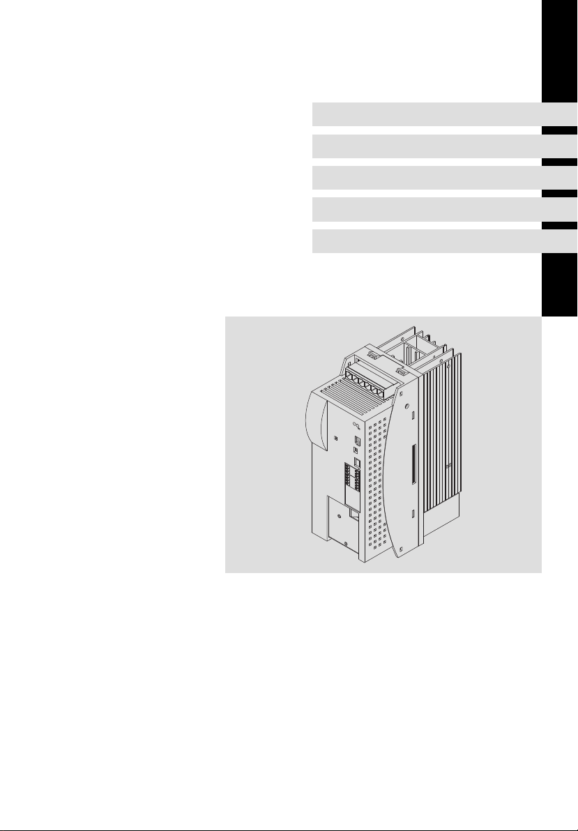
Versorgungsmodul "Durchstoß−Technik"
Power supply module in push−through technique
Module d’alimentation en montage traversant
Page 2

Lesen Sie zuerst diese Anleitung, bevor Sie mit den Arbeiten beginnen!
Beachten Sie die enthaltenen Sicherheitshinweise.
Please read these instructions before you start working!
Follow the enclosed safety instructions.
Veuillez lire attentivement cette documentation avant toute action !
Les consignes de sécurité doivent impérativement être respectées.
Page 3
ECSDE_002A
Page 4

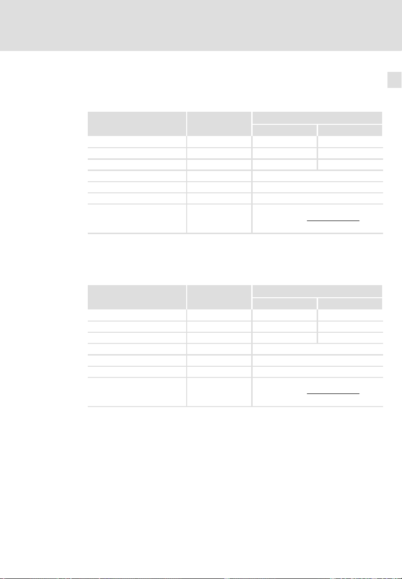
Lieferumfang
Position Beschreibung Anzahl
Versorgungsmodul ECSDExxx 1
Beipack mit Befestigungsmaterial 1
Montageanleitung 1
Bohrschablone 1
Hinweis!
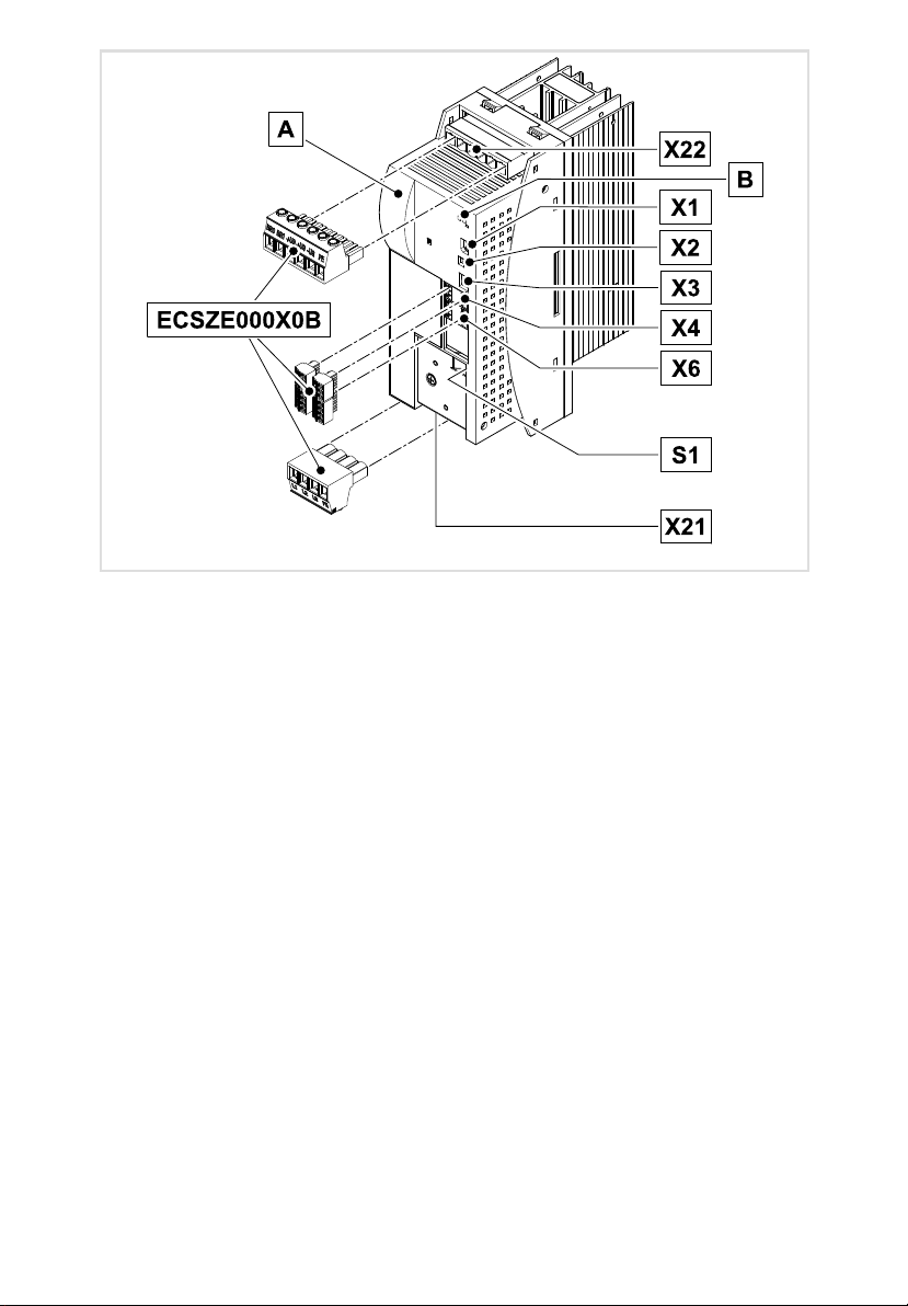
Das Steckverbinder−Set ECSZE000X0B muss gesondert bezogen werden.
Anschlüsse und Schnittstellen
Position Beschreibung Ausführliche
X22 Anschlüsse
LEDs: Anzeige Status und Störung
X1 Automatisierungs−Interface (AIF) für
X2 PE−Anschluss AIF
X3 nicht belegt
X4 Anschluss CAN
X6 Anschlüsse
S1 DIP−Schalter
X21 Anschluss Netz 35
l Externer Bremswiderstand
l DC−Zwischenkreisspannung
l PE
l Kommunikationsmodul
l Bedienmodul (Keypad XT)
l Systembus (CAN)
l Schnittstelle für
– übergeordnete Steuerung und weitere Module
– PC / HMI zur Parametrierung und Diagnose
l Niederspannungsversorgung
l Digitale Eingänge und Ausgänge
l Temperaturschalter−Kontakte
l CAN−Knotenadresse (Geräteadresse im CAN−Netzwerk)
l CAN−Übertragungsrate
Informationen
38
51
52
50
Statusanzeigen
LED
rot grün
aus an Versorgungsmodul freigegeben, keine Störung
aus blinkt Versorgungsmodul gesperrt (CINH), Einschaltsperre
blinkt, 1−mal/s aus Störung / Fehler (TRIP) / Fehler KSB (KSB−TRIP) aktiv
blinkt, 3−mal/s aus Meldung aktiv
blinkt, 1−mal/s blinkt Warnung bei gesperrtem Modul aktiv
blinkt, 1−mal/s an Warnung bei freigegebenem Modul aktiv
Beschreibung
4
EDKCSDE040 DE/EN/FR 4.0
Page 5
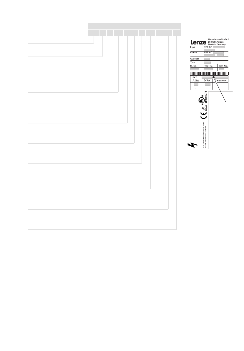
Diese Anleitung ist gültig für Versorgungsmodule ECSDE... ab dem Gerätestand:
ECS D E xxx x 4 x xxx XX xx xx
Gerätetyp
Bauform
E = Standard−Einbaugerät IP20
D = Durchstoß−Technik (therm. separiert)
C = Cold−Plate−Technik
Bemessungsstrom
012 = 12 A
020 = 20 A
040 = 38,5 A
Feldbus−Schnittstelle
C = Systembus CAN
ATTENTION
L ´appareil est sous tension
pendant 180s après la coupure
de la tension réseau
Spannungsklasse
4 = 400 V/480 V
Technische Ausführung
B = Standard
V = verlackt
Variante
Stand Hardware
VA oder höher
Stand Betriebssoftware (B−SW)
1.2 oder höher
WARNING
Device is live up to 180s
after removing
mains voltage
EDKCSDE040 DE/EN/FR 4.0
5
Page 6

Tipp!
Informationen und Hilfsmittel rund um die Lenze−Produkte finden Sie im
Download−Bereich unter
http://www.Lenze.com
0Abb. 0Tab. 0
© 2013 Lenze Automation GmbH, Postfach 10 13 52, D−31763 Hameln, Hans−Lenze−Str. 1, D−31855 Aerzen
Ohne besondere schriftliche Genehmigung von Lenze Automation GmbH darf kein Teil dieser Dokumentation
vervielfältigt oder Dritten zugänglich gemacht werden.
Wir haben alle Angaben in dieser Dokumentation mit größter Sorgfalt zusammengestellt und auf Übereinstimmung mit der beschriebenen Hard− und Software geprüft. Trotzdem können wir Abweichungen nicht ganz ausschließen. Wir übernehmen keine juristische Verantwortung oder Haftung für Schäden, die dadurch eventuell
entstehen. Notwendige Korrekturen werden wir in die nachfolgenden Auflagen einarbeiten.
6
EDKCSDE040 DE/EN/FR 4.0
Page 7

Inhalt i
1 Sicherheitshinweise 8. . . . . . . . . . . . . . . . . . . . . . . . . . . . . . . . . . . . . . . . . . . . . . .
1.1 Allgemeine Sicherheits− und Anwendungshinweise für
Lenze−Versorgungsmodule 8. . . . . . . . . . . . . . . . . . . . . . . . . . . . . . . . . . .
1.2 Restgefahren 12. . . . . . . . . . . . . . . . . . . . . . . . . . . . . . . . . . . . . . . . . . . . . . .
1.3 Sicherheitshinweise für die Installation nach UL 14. . . . . . . . . . . . . . . . .
1.4 Verwendete Hinweise 15. . . . . . . . . . . . . . . . . . . . . . . . . . . . . . . . . . . . . . .
2 Technische Daten 17. . . . . . . . . . . . . . . . . . . . . . . . . . . . . . . . . . . . . . . . . . . . . . . . .
2.1 Allgemeine Daten und Einsatzbedingungen 17. . . . . . . . . . . . . . . . . . .
2.2 Bemessungsdaten 19. . . . . . . . . . . . . . . . . . . . . . . . . . . . . . . . . . . . . . . . . .
2.3 Externe Bremswiderstände 20. . . . . . . . . . . . . . . . . . . . . . . . . . . . . . . . . . .
3 Mechanische Installation 22. . . . . . . . . . . . . . . . . . . . . . . . . . . . . . . . . . . . . . . . . . .
3.1 Wichtige Hinweise 22. . . . . . . . . . . . . . . . . . . . . . . . . . . . . . . . . . . . . . . . . .
3.2 Montage mit thermischer Separierung (Durchstoß−Technik) 23. . . . . . .
3.2.1 Abmessungen 24. . . . . . . . . . . . . . . . . . . . . . . . . . . . . . . . . . . . .
3.2.2 Montageschritte 26. . . . . . . . . . . . . . . . . . . . . . . . . . . . . . . . . .
4 Elektrische Installation 27. . . . . . . . . . . . . . . . . . . . . . . . . . . . . . . . . . . . . . . . . . . . .
4.1 EMV−gerechte Installation
(Aufbau des CE−typischen Antriebssystems) 27. . . . . . . . . . . . . . . . . . . . .
4.2 Antriebssystem am Netz 30. . . . . . . . . . . . . . . . . . . . . . . . . . . . . . . . . . . . .
4.2.1 Potenzialtrennung 30. . . . . . . . . . . . . . . . . . . . . . . . . . . . . . . . .
4.2.2 Netzformen / Netzbedingungen 31. . . . . . . . . . . . . . . . . . . . .
4.2.3 Betrieb an öffentlichen Netzen
(Einhaltung der EN 61000−3−2) 32. . . . . . . . . . . . . . . . . . . . . . .
4.3 Leistungsanschlüsse 33. . . . . . . . . . . . . . . . . . . . . . . . . . . . . . . . . . . . . . . . .
4.3.1 Netzanschluss 35. . . . . . . . . . . . . . . . . . . . . . . . . . . . . . . . . . . .
4.3.2 Anschluss an den DC−Zwischenkreis (+UG, −UG) 38. . . . . . . .
4.3.3 Anschlussplan für die Mindestverdrahtung mit
internem Bremswiderstand 39. . . . . . . . . . . . . . . . . . . . . . . . .
4.3.4 Anschlussplan für die Mindestverdrahtung mit
externem Bremswiderstand 41. . . . . . . . . . . . . . . . . . . . . . . . .
4.3.5 Anschluss eines Kondensatormoduls ECSxK...
(optional) 44. . . . . . . . . . . . . . . . . . . . . . . . . . . . . . . . . . . . . . . .
4.4 Steueranschlüsse 46. . . . . . . . . . . . . . . . . . . . . . . . . . . . . . . . . . . . . . . . . . .
4.5 Automatisierungs−Interface (AIF) 51. . . . . . . . . . . . . . . . . . . . . . . . . . . . . .
4.6 Systembus (CAN) verdrahten 52. . . . . . . . . . . . . . . . . . . . . . . . . . . . . . . . .
5 Installation überprüfen 57. . . . . . . . . . . . . . . . . . . . . . . . . . . . . . . . . . . . . . . . . . . .
EDKCSDE040 DE/EN/FR 4.0
7
Page 8

1
Sicherheitshinweise
Allgemeine Sicherheits− und Anwendungshinweise für
Lenze−Versorgungsmodule
1 Sicherheitshinweise
1.1 Allgemeine Sicherheits− und Anwendungshinweise für
Lenze−Versorgungsmodule
(gemäß Niederspannungsrichtlinie 2006/95/EG)
Zu Ihrer persönlichen Sicherheit
Wenn Sie die folgenden grundlegenden Sicherheitsmaßnahmen missachten,
kann dies zu schweren Personenschäden und Sachschäden führen:
ƒ Das Produkt ausschließlich bestimmungsgemäß verwenden.
ƒ Das Produkt niemals trotz erkennbarer Schäden in Betrieb nehmen.
ƒ Das Produkt niemals unvollständig montiert in Betrieb nehmen.
ƒ Keine technischen Änderungen am Produkt vornehmen.
ƒ Nur das für das Produkt zugelassene Zubehör verwenden.
ƒ Nur Original−Ersatzteile des Herstellers verwenden.
ƒ Alle am Einsatzort geltenden Unfallverhütungsvorschriften, Richtlinien
und Gesetze beachten.
ƒ Nur qualifiziertes Fachpersonal die Arbeiten zum Transport, zur
Installation, zur Inbetriebnahme und zur Instandhaltung ausführen
lassen.
– IEC 364 bzw. CENELEC HD 384 oder DIN VDE 0100 und IEC−Report 664
oder DIN VDE 0110 und nationale Unfallverhütungsvorschriften
beachten.
– Qualifiziertes Fachpersonal im Sinne dieser grundsätzlichen
Sicherheitshinweise sind Personen, die mit Aufstellung, Montage,
Inbetriebsetzung und Betrieb des Produkts vertraut sind und die über
die ihrer Tätigkeit entsprechenden Qualifikationen verfügen.
ƒ Alle Vorgaben dieser Dokumentation beachten.
– Dies ist Voraussetzung für einen sicheren und störungsfreien Betrieb
sowie für das Erreichen der angegebenen Produkteigenschaften.
– Die in dieser Dokumentation dargestellten verfahrenstechnischen
Hinweise und Schaltungsausschnitte sind Vorschläge, deren
Übertragbarkeit auf die jeweilige Anwendung überprüft werden muss.
Für die Eignung der angegebenen Verfahren und Schaltungsvorschläge
übernimmt Lenze Automation GmbH keine Gewähr.
8
EDKCSDE040 DE/EN/FR 4.0
Page 9

Sicherheitshinweise
Allgemeine Sicherheits− und Anwendungshinweise für
Lenze−Versorgungsmodule
ƒ Lenze−Versorgungsmodule und zugehörige Komponenten können
während des Betriebs ˘ ihrer Schutzart entsprechend ˘
spannungsführende Teile haben. Oberflächen können heiß sein.
– Bei unzulässigem Entfernen der erforderlichen Abdeckung, bei
unsachgemäßem Einsatz, bei falscher Installation oder Bedienung
besteht die Gefahr von schweren Personen− oder Sachschäden.
– Weitere Informationen entnehmen Sie der Dokumentation.
ƒ Im Versorgungsmodul treten hohe Energien auf. Deshalb bei Arbeiten am
Versorgungsmodul unter Spannung immer eine persönliche
Schutzausrüstung tragen (Körperschutz, Kopfschutz, Augenschutz,
Gehörschutz, Handschutz).
Bestimmungsgemäße Verwendung
Versorgungsmodule sind Komponenten, die zum Einbau in elektrische Anlagen
oder Maschinen bestimmt sind. Sie sind keine Haushaltsgeräte, sondern als
Komponenten ausschließlich für die Verwendung zur gewerblichen Nutzung
bzw. professionellen Nutzung im Sinne der EN 61000−3−2 bestimmt.
Bei Einbau der Versorgungsmodule in Maschinen ist die Inbetriebnahme (d. h.
die Aufnahme des bestimmungsgemäßen Betriebs) solange untersagt, bis festgestellt wurde, dass die Maschine den Bestimmungen der EG−Richtlinie 2006/42/EG (Maschinenrichtlinie) entspricht; EN 60204 beachten.
Die Inbetriebnahme (d. h. die Aufnahme des bestimmungsgemäßen Betriebs)
ist nur bei Einhaltung der EMV−Richtlinie (2004/108/EG) erlaubt.
Die Versorgungsmodule erfüllen die Anforderungen der Niederspannungsrichtlinie 2006/95/EG. Die harmonisierte Norm EN 61800−5−1 wird für die Versorgungsmodule angewendet.
Die technischen Daten und die Angaben zu Anschlussbedingungen entnehmen
Sie dem Leistungsschild und der Dokumentation. Halten Sie diese unbedingt
ein.
Warnung: Die Versorgungsmodule sind Produkte, die nach EN 61800−3 in Antriebssysteme der Kategorie C2 eingesetzt werden können. Diese Produkte können im Wohnbereich Funkstörungen verursachen. In diesem Fall kann es für den
Betreiber erforderlich sein, entsprechende Maßnahmen durchzuführen.
Transport, Einlagerung
Beachten Sie die Hinweise für Transport, Lagerung und sachgemäße Handhabung.
Halten Sie die klimatischen Bedingungen gemäß den technischen Daten ein.
1
EDKCSDE040 DE/EN/FR 4.0
9
Page 10

1
Sicherheitshinweise
Allgemeine Sicherheits− und Anwendungshinweise für
Lenze−Versorgungsmodule
Aufstellung
Sie müssen die Versorgungsmodule nach den Vorschriften der zugehörigen Dokumentation aufstellen und kühlen.
Die Umgebungsluft darf den Verschmutzungsgrad 2 nach EN 61800−5−1 nicht
überschreiten.
Sorgen Sie für sorgfältige Handhabung und vermeiden Sie mechanische Überlastung. Verbiegen Sie bei Transport und Handhabung weder Bauelemente noch
ändern Sie Isolationsabstände. Berühren Sie keine elektronischen Bauelemente
und Kontakte.
Versorgungsmodule enthalten elektrostatisch gefährdete Bauelemente, die Sie
durch unsachgemäße Handhabung leicht beschädigen können. Beschädigen
oder zerstören Sie keine elektrischen Komponenten, da Sie dadurch Ihre Gesundheit gefährden können!
Elektrischer Anschluss
Beachten Sie bei Arbeiten an unter Spannung stehenden Versorgungsmodule
die geltenden nationalen Unfallverhütungsvorschriften (z. B. VBG 4).
Führen Sie die elektrische Installation nach den einschlägigen Vorschriften
durch (z. B. Leitungsquerschnitte, Absicherungen, Schutzleiteranbindung). Zusätzliche Hinweise enthält die Dokumentation.
Die Dokumentation enthält Hinweise für die EMV−gerechte Installation (Schirmung, Erdung, Anordnung von Filtern und Verlegung der Leitungen). Beachten
Sie diese Hinweise ebenso bei CE−gekennzeichneten Versorgungsmodulen und
Antriebsreglern. Der Hersteller der Anlage oder Maschine ist verantwortlich für
die Einhaltung der im Zusammenhang mit der EMV−Gesetzgebung geforderten
Grenzwerte. Um die am Einbauort geltenden Grenzwerte für Funkstöraussendungen einzuhalten, müssen Sie die Versorgungsmodule in Gehäuse
(z. B. Schaltschränke) einbauen. Die Gehäuse müssen einen EMV−gerechten
Aufbau ermöglichen. Achten Sie besonders darauf, dass z. B. Schaltschranktüren möglichst umlaufend metallisch mit dem Gehäuse verbunden sind. Öffnungen oder Durchbrüche durch das Gehäuse auf ein Minimum reduzieren.
10
EDKCSDE040 DE/EN/FR 4.0
Page 11

Sicherheitshinweise
Allgemeine Sicherheits− und Anwendungshinweise für
Lenze−Versorgungsmodule
Betrieb
Sie müssen Anlagen mit eingebauten Versorgungsmodulen ggf. mit zusätzlichen Überwachungs− und Schutzeinrichtungen gemäß den jeweils gültigen Sicherheitsbestimmungen ausrüsten (z. B. Gesetz über technische Arbeitsmittel,
Unfallverhütungsvorschriften). Sie dürfen die Versorgungsmodule an Ihre Anwendung anpassen. Beachten Sie dazu die Hinweise in der Dokumentation.
Nachdem das Versorgungsmodul von der Versorgungsspannung getrennt ist,
dürfen Sie spannungsführende Geräteteile und Leistungsanschlüsse nicht sofort berühren, weil Kondensatoren aufgeladen sein können. Beachten Sie dazu
die entsprechenden Hinweisschilder auf dem Versorgungsmodul.
Halten Sie während des Betriebs alle Schutzabdeckungen und Türen geschlossen.
Hinweis für UL−approbierte Anlagen mit eingebauten Antriebsreglern: UL warnings sind Hinweise, die nur für UL−Anlagen gelten. Die Dokumentation enthält
spezielle Hinweise zu UL.
Wartung und Instandhaltung
Die Versorgungsmodule sind wartungsfrei, wenn die vorgeschriebenen Einsatzbedingungen eingehalten werden.
Entsorgung
Metalle und Kunststoffe zur Wiederverwertung geben. Bestückte Leiterplatten
fachgerecht entsorgen.
Beachten Sie unbedingt die produktspezifischen Sicherheits− und Anwendungshinweise in dieser Anleitung!
1
EDKCSDE040 DE/EN/FR 4.0
11
Page 12

1
1.2 Restgefahren
Sicherheitshinweise
Restgefahren
Personenschutz
ƒ Überprüfen Sie vor Arbeiten am Versorgungsmodul, ob alle
Leistungsklemmen spannungslos sind, da
– nach dem Abschalten der Netzspannung die Leistungsklemmen +UG,
−UG, BR0 und BR1 noch mindestens 3 Minuten gefährliche Spannung
führen.
– bei gestopptem Motor die Leistungsklemmen +UG, −UG, BR0 und BR1
gefährliche Spannung führen.
ƒ Die Betriebstemperatur des Kühlkörpers ist > 70 °C:
– Hautkontakt mit dem Kühlkörper führt zu Verbrennungen.
ƒ Der Ableitstrom gegen PE ist > 3,5 mA AC bzw. > 10 mA DC.
– Nach EN 61800−5−1 ist eine Festinstallation erforderlich.
– Der PE−Anschluss muss nach EN 61800−5−1 ausgeführt sein.
– Weitere Bedingungen der EN 61800−5−1 für hohen Ableitstrom
einhalten.
ƒ Betrieb des Versorgungsmoduls am Fehlerstrom−Schutzschalter:
– Die Versorgungsmodule verfügen intern über einen Netzgleichrichter.
Bei einem Körperschluss kann ein nicht pulsierender Fehler−Gleichstrom
die Auslösung wechselstromsensitiver bzw. pulsstromsensitiver
Fehlerstrom−Schutzschalter blockieren und somit die Schutzfunktion
für alle an diesem Fehlerstrom−Schutzschalter betriebenen
Betriebsmittel aufheben.
– Wird für den Schutz bei einer direkten oder indirekten Berührung ein
Differenzstromgerät (RCD) verwendet, ist nur ein Differenzstromgerät
(RCD) vom Typ B zulässig. Anderenfalls muss eine andere
Schutzmaßnahme angewendet werden, wie z. B. Trennung von der
Umgebung durch doppelte oder verstärkte Isolierung oder Trennung
vom Versorgungsnetz durch einen Transformator.
12
EDKCSDE040 DE/EN/FR 4.0
Page 13

Sicherheitshinweise
Restgefahren
Geräteschutz
ƒ Das Versorgungsmodul ist ausschließlich für den Betrieb an
symmetrischen Netzen zugelassen. Ein Betrieb an Außenleiter−geerdeten
Netzen ist nicht zulässig.
ƒ Das Versorgungsmodul enthält elektrostatisch gefährdete Bauelemente.
Vor Arbeiten im Bereich der Anschlüsse muss sich das Personal von
elektrostatischen Aufladungen befreien.
ƒ Alle steckbaren Anschlussklemmen nur im spannungslosen Zustand
aufstecken oder abziehen!
ƒ Die Leistungsklemmen +UG, −UG und PE sind nicht verpolungssicher
ausgelegt.
– Polarität der Leistungsklemmen beim Verdrahten beachten!
ƒ Beachten Sie die maximal zulässige Netzspannung. Eine höhere
Spannung zerstört das Versorgungsmodul.
ƒ Der Betrieb ist nicht zulässig
– ohne Verwendung eines Bremswiderstandes.
– bei gleichzeitiger Verwendung des internen Bremswiderstandes mit
einem externen Bremswiderstand.
– bei Parallelschaltung mehrerer Versorgungsmodule.
1
EDKCSDE040 DE/EN/FR 4.0
13
Page 14

1
1.3 Sicherheitshinweise für die Installation nach UL
Sicherheitshinweise
Sicherheitshinweise für die Installation nach UL
Warnings!
General markings:
ƒ Use 60/75 °C or 75 °C copper wire only.
ƒ Maximum ambient temperature 55 °C, with reduced output
current.
Markings provided for the supply units:
ƒ Suitable for use on a circuit capable of delivering not more than
5000 rms symmetrical amperes, 480 V max, when protected by
K5 or H Fuses (400/480 V devices).
ƒ Alternate − Circuit breakers (either inverse−time, instantaneous
trip types or combination motor controller type E) may be used in
lieu of above fuses when it is shown that the let−through
energy (i
current−limiting circuit breaker will be less than that of the
non−semiconductor type K5 fuses with which the drive has been
tested.
ƒ Alternate − An inverse−time circuit breaker may be used, sized
upon the input rating of the drive, multiplied by 300 %.
Markings provided for the inverter units:
ƒ The inverter units shall be used with supply units which are
provided with overvoltage devices or systems in accordance with
UL840 2nd ed., Table 5.1.
ƒ The devices are provided with integral overload and integral
thermal protection for the motor.
ƒ The devices are not provided with overspeed protection.
Terminal tightening torque of lb−in (Nm)
2
t) and peak let−through current (Ip) of the inverse−time
14
Terminal lb−in Nm
X 21, X 22, X 23, X 24 10.6 ... 13.3 1.2 ... 1.5
X4, X6, X14 1.95 ... 2.2 0.22 ... 0.25
X 25 4.4 ... 7.1 0.5 ... 0.8
Wiring diagram AWG
Terminal AWG
X 21, X 22, X 23, X 24 12 ... 8
X4, X6, X14 28 ... 16
X 25 24 ... 12
EDKCSDE040 DE/EN/FR 4.0
Page 15

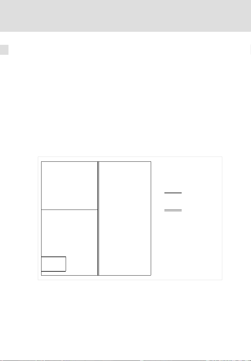
1.4 Verwendete Hinweise
Um auf Gefahren und wichtige Informationen hinzuweisen, werden in dieser
Dokumentation folgende Piktogramme und Signalwörter verwendet:
Sicherheitshinweise
Aufbau der Sicherheitshinweise:
Gefahr!
(kennzeichnet die Art und die Schwere der Gefahr)
Hinweistext
(beschreibt die Gefahr und gibt Hinweise, wie sie vermieden werden
kann)
Piktogramm und Signalwort Bedeutung
Gefahr!
Gefahr!
Stop!
Anwendungshinweise
Sicherheitshinweise
Verwendete Hinweise
Gefahr von Personenschäden durch gefährliche elektrische Spannung
Hinweis auf eine unmittelbar drohende Gefahr, die den
Tod oder schwere Verletzungen zur Folge haben kann,
wenn nicht die entsprechenden Maßnahmen getroffen
werden.
Gefahr von Personenschäden durch eine allgemeine
Gefahrenquelle
Hinweis auf eine unmittelbar drohende Gefahr, die den
Tod oder schwere Verletzungen zur Folge haben kann,
wenn nicht die entsprechenden Maßnahmen getroffen
werden.
Gefahr von Sachschäden
Hinweis auf eine mögliche Gefahr, die Sachschäden zur
Folge haben kann, wenn nicht die entsprechenden Maßnahmen getroffen werden.
1
Piktogramm und Signalwort Bedeutung
Hinweis!
Tipp!
EDKCSDE040 DE/EN/FR 4.0
Wichtiger Hinweis für die störungsfreie Funktion
Nützlicher Tipp für die einfache Handhabung
Verweis auf andere Dokumentation
15
Page 16

1
Sicherheitshinweise
Verwendete Hinweise
Spezielle Sicherheitshinweise und Anwendungshinweise für UL und UR
Piktogramm und Signalwort Bedeutung
Sicherheitshinweis oder Anwendungshinweis für den
Betrieb eines UL−approbierten Geräts in UL−approbier-
Warnings!
Warnings!
ten Anlagen.
Möglicherweise wird das Antriebssystem nicht UL−gerecht betrieben, wenn nicht die entsprechenden Maßnahmen getroffen werden.
Sicherheitshinweis oder Anwendungshinweis für den
Betrieb eines UR−approbierten Geräts in UL−approbierten Anlagen.
Möglicherweise wird das Antriebssystem nicht UL−gerecht betrieben, wenn nicht die entsprechenden Maßnahmen getroffen werden.
16
EDKCSDE040 DE/EN/FR 4.0
Page 17

Technische Daten
Allgemeine Daten und Einsatzbedingungen
2 Technische Daten
2.1 Allgemeine Daten und Einsatzbedingungen
Normen und Einsatzbedingungen
Konformität CE
Approbationen
Verpackung (DIN 4180) Versandverpackung
Einbau Einbau in Schaltschrank
Einbaulage senkrechthängend
Einbaufreiräume
Umweltbedingungen
Klima 3k3 nach IEC/EN 60721−3−3
Lagerung IEC/EN 60721−3−1 1K3 (−25 ... + 55 °C)
Transport IEC/EN 60721−3−2 2K3 (−25 ... +70 °C)
Betrieb IEC/EN 60721−3−3 3K3 (0 ... + 55 °C)
Aufstellhöhe 0 ... 4000 m üNN
Verschmutzung EN 61800−5−1, UL840: Verschmutzungsgrad 2
Vibrationsfestigkeit Beschleunigungsfest bis 0,7 g (Germanischer Lloyd, allgemeine Bedingungen)
oberhalb ³ 65 mm
unterhalb ³ 65 mm
seitlich ohne Abstand anreihbar
Betauung, Spritzwasser und Eisbildung
nicht zulässig.
UL 508C
CSA 22.2 No. 14
mit Schirmbefestigungs−Set ECSZS000X0B: > 195 mm
Niederspannungsrichtlinie (2006/95/EG)
Power Conversion Equipment
Underwriter Laboratories (File No. E132659)
für USA und Kanada
l Luftdruck: 86 ... 106 kPa
l Über +40 °C: Ausgangs−Bemessungs-
strom um 2 %/°C reduzieren.
l Über 1000 m üNN: Ausgangs−Bemes-
sungsstrom um 5 %/1000 m reduzieren.
l Über 2000 m üNN: Einsatz nur er-
laubt in Umgebungen mit Überspannungskategorie II
2
EDKCSDE040 DE/EN/FR 4.0
17
Page 18

2
Technische Daten
Allgemeine Daten und Einsatzbedingungen
Allgemeine elektrische Daten
EMV Einhaltung der Anforderungen nach EN 61800−3
Störaussendung Einhaltung der Grenzwertklasse C2 nach EN 61800−3(erreicht mit an-
Störfestigkeit
Isolationsfestigkeit EN 61800−5−1, UL 840: Überspannungskategorie III
Ableitstrom gegen PE
(nach EN 61800−5−1)
Schutzart IP20 bei
Schutzmaßnahmen gegen l Kurzschluss Leistungsklemmen (kurzschlussfest beim Netz−Einschal-
Schutzisolierung von Steuerschaltkreisen
1)
Die Störfestigkeit in den genannten Schärfegraden muss durch den Schaltschrank
gewährleistet sein. Der Anwender muss die Einhaltung der genannten Schärfegrade
prüfen.
wendungstypischem Summenfilter)
Anforderungen nach EN 61800−3
Anforderung Norm Schärfegrade
1)
ESD
leitungsgeführte Hochfrequenz
HF−Einstrahlung (Gehäuse)
Burst EN 61000−4−4 3/4, d. h. 2 kV/5 kHz
Surge (Stoßspannung
auf Netzleitung)
> 3,5 mA AC
l Standardmontage (Einbaugerät)
l Montage in Cold−Plate−Technik
l Montage mit thermischer Separierung (Durchstoß−Technik), IP54 auf
der Kühlkörperseite
ten)
l Kurzschluss Hilfsstromkreise
– Digital−Ausgänge: kurzschlussfest
– Bus− und Gebersysteme: eingeschränkt kurzschlussfest (Ggf. kön-
nen Überwachungsfunktionen abschalten. Störungsmeldungen
müssen dann zurückgesetzt werden.)
l Erdschluss (erdschlussfest beim Netz−Einschalten)
l Überspannung
Schutztrennung vom Netz
Doppelte/verstärkte Isolierung nach EN 61800−5−1
EN 61000−4−2 3, d. h.
EN 61000−4−6 10 V; 0,15 ... 80 MHz
EN 61000−4−3 3, d. h. 10 V/m;
EN 61000−4−5 3, d. h. 1,2/50 ms
l 8 kV bei Luftentladung
l 6 kV bei Kontaktentla-
dung
80 ... 1000 MHz
l 1 kV Phase−Phase
l 2 kV Phase−PE
18
EDKCSDE040 DE/EN/FR 4.0
Page 19

Technische Daten
Bemessungsdaten
2
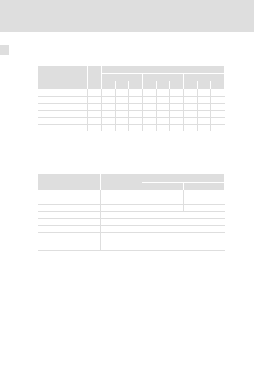
2.2 Bemessungsdaten
Bemessungsdaten Typ ECSxE012 ECSxE020 ECSxE040
Netzspannung U
Netzbemessungsspannung U
Netzfrequenz f
Netzbemessungsstrom I
maximaler Netzstrom
Bemessungsgleichstrom (Effektivwert)
max. anschließbare Zwischenkreiskapazität
Niederspannungsversorgung der
Steuerelektronik
Verlustleistung, gesamt
Geräteinnenraum 20 23 30
Kühlkörper 30 45 81
Geschwindigkeit der Kühlluft
(nur bei ECSDE...)
Masse m [kg] ca. 2,5 ca. 3,2
Interner Bremswiderstand
(nicht vorhanden bei ECSCE...)
Dauerleistung Pd [kW] 0,12 0,15
max. Bremsleistung P
max. Bremsenergie WB [kWs] 2,5 3,0
max. Einschaltzeit te [s] 0,15 0,10
notwendige Erholzeit ta [s] 20
1)
Für die Bemessung einer 24−V−Versorgung ggf. den Strombedarf des digitalen Ausgangs
(0,7 A) addieren.
[V] 3 x 200 −10 % ... 3 x 480 +10 %
Netz
[V] 3 x 400 V
Netz N
[Hz] 45 ... 66
Netz
[A] 9,6 15,9 31,3
Netz N
5 x I
für 50 ms / 0 x I
Netz N
2 x I
I
[A]
Netz max
1,5 x I
I
[A] 12,0 20,0 38,5
DC N,RMS
Netz N
für 10 s / 0 x I
Netz N
für 1 s / 0 x I
Netz N
Netz N
Netz N
C [uF] 6600
U [V] 20 ... 30
I
[A] 0,35
typ.
I
[A] 0,5 A bei 24 V
max
1)
50 68 111
PV [W]
VC [m/s] 3
RB [] 39 20
[kW] 13,8 27,0
Bmax
für 1,2 s
für 3 s
für 12,75 s
EDKCSDE040 DE/EN/FR 4.0
19
Page 20
2
Technische Daten
Externe Bremswiderstände
2.3 Externe Bremswiderstände
Zuordnung externer Bremswiderstände
Bremswider-
stand
ERBM039R120W 39 0,12 l l
ERBM020R150W 20 0,15 l
ERBD047R01K2 47 1,20 l l l l l l
ERBD022R03K0 22 3,00 l l l
ERBS039R01K6 39 1,64 l l l l l l
ERBS020R03K2 20 3,20 l l l
PdDauerleistung
P
W
[kW]
Bremswiderstände Typ ERBM...
Bremswiderstände mit speziell abgestimmter Impulsfähigkeit in IP50−Ausführung
Bemessungsdaten Typ
Widerstand RB [] 39 20
Dauerleistung Pd [W] 120 150
Wärmemenge QB [kWs] 6 13
Max. Einschaltzeit te [s] 5
Notwendige Erholzeit ta [s] 90
Betriebsspannung U
Max. Bremsleistung P
Versorgungsmodul (Standard−Varianten)
d
ECSEE... ECSDE... ECSCE...
012 020 040 012 020 040 012 020 040
Bremswiderstand
ERBM039R120W ERBM020R150W
[VDC] 800
max
Bmax
[kW]
P
Bmax
WärmemengeQ
+
Einschaltzeit
B
20
EDKCSDE040 DE/EN/FR 4.0
Page 21
Technische Daten
Externe Bremswiderstände
Bremswiderstände Typ ERBD...
Bremswiderstände mit erhöhter Verlustleistung in IP20−Ausführung (Berührschutz nach NEMA 250 Typ 1)
2
Bemessungsdaten Typ
ERBD047R01K2 ERBD022R03K0
Widerstand RB [] 47 22
Dauerleistung Pd [W] 1200 3000
Wärmemenge QB [kWs] 174 375
Max. Einschaltzeit te [s] 15
Motwendige Erholzeit ta [s] 135
Betriebsspannung U
Max. Bremsleistung P
[VDC] 800
max
[kW]
Bmax
Bremswiderstand
P
+
Bmax
WärmemengeQ
Einschaltzeit
B
Bremswiderstände Typ ERBS...
Bremswiderstände mit erhöhter Verlustleistung in IP65−Ausführung
(NEMA 250 Typ 4x)
Bemessungsdaten Typ
ERBS039R01K6 ERBS020R03K2
Widerstand RB [] 39 20
Dauerleistung Pd [W] 1640 3200
Wärmemenge QB [kWs] 246 480
Max. Einschaltzeit te [s] 15
Notwendige Erholzeit ta [s] 135
Betriebsspannung U
Max. Bremsleistung P
[VDC] 800
max
[kW]
Bmax
Bremswiderstand
P
+
Bmax
WärmemengeQ
Einschaltzeit
B
EDKCSDE040 DE/EN/FR 4.0
21
Page 22

3
Mechanische Installation
Wichtige Hinweise
3 Mechanische Installation
3.1 Wichtige Hinweise
ƒ Versorgungsmodule der Reihe ECS verfügen über die Schutzart IP20 und
sind daher nur für den Einbau in Schaltschränken bestimmt.
ƒ Bei verunreinigter Kühlluft (Staub, Flusen, Fette, aggressive Gase):
– Ausreichende Gegenmaßnahmen treffen, z. B. separate Luftführung,
Einbau von Filtern, regelmäßige Reinigung.
ƒ Mögliche Einbaulagen
– Senkrecht an der Montageplatte
– Zwischenkreisanschlüsse (X22) oben
– Netzanschluss (X21) unten
ƒ Halten Sie die angegebenen Einbaufreiräume oberhalb und unterhalb zu
anderen Installationen ein!
– Bei Verwendung des Schirmbefestigungs−Set ECSZS000X0B ist ein
zusätzlicher Freiraum erforderlich.
– Achten Sie auf ungehinderten Zutritt der Kühlluft und ungehinderten
Austritt der Abluft.
– Sie können mehrere Module der Reihe ECS im Schaltschrank ohne
Zwischenraum nebeneinander befestigen.
ƒ Die Montageplatte des Schaltschranks
– muss elektrisch leitfähig sein.
– darf nicht lackiert sein.
ƒ Bei dauerhaften Schwingungen oder Erschütterungen den Einsatz von
Schwingungsdämpfern prüfen.
22
EDKCSDE040 DE/EN/FR 4.0
Page 23

Mechanische Installation
Montage mit thermischer Separierung (Durchstoß−Technik)
3.2 Montage mit thermischer Separierung (Durchstoß−Technik)
Bei Durchstoß−Technik muss die Rückwand des Schaltschranks eine mindestens
3 mm starke Stahlplatte sein.
Die Kanten des Einbauausschnitts und der Befestigungsbohrungen für die
Klemmbügel müssen leicht nach innen (zum ECS−Modul) gewölbt sein.
Kühlung
Mit dem separierten Kühlkörper reduzieren Sie die Wärmeentwicklung im
Schaltschrank.
ƒ Aufteilung der Verlustleistung:
– ca. 65 % über separarierten Kühler
– ca. 35 % im Innenraum des ECS−Moduls
ƒ Schutzklasse des separierten Kühlers: IP54
– Die Dichtfläche des ECS−Moduls am Kühlkörper muss vollständig an der
Montageplatte aufliegen.
– Schrauben für Klemmbügel mit flüssiger Gewindedichtung verkleben.
ƒ Kühlung des Antriebssystems:
– Luftstrom hinter der Rückwand des Schaltschranks ³ 3 m/s (z. B. durch
Verwendung eines Summenlüfters).
ƒ Bei ausreichender Kühlung gelten weiterhin die Bemessungsdaten.
3
EDKCSDE040 DE/EN/FR 4.0
23
Page 24
3
Mechanische Installation
Montage mit thermischer Separierung (Durchstoß−Technik)
Abmessungen
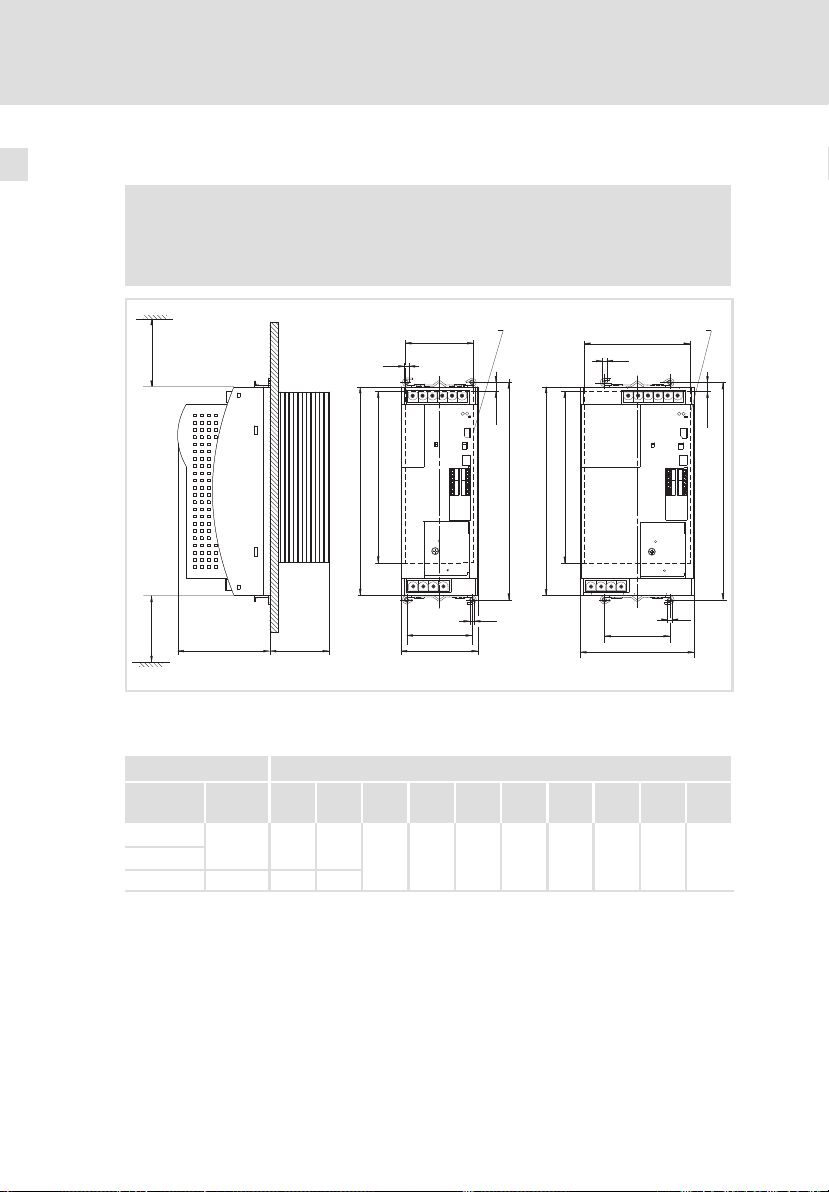
3.2.1 Abmessungen
Hinweis!
Montage mit Schirmbefestigung ECSZS000X0B:
ƒ Einbaufreiraum unterhalb des Moduls > 195 mm
³ 65 mm
³ 65 mm
Abb. 3−1 Abmessungen bei Bauform "Durchstoß−Technik"
Z Einbauausschnitt (a1 x b1), 25
0
Z
a1
g
h
b1
b
g
e
e1
c1
a
b1
d
b
1
a1
g
c1
a
Z
h
d
g
ECSXA007
24
Versorgungsmodul Maße [mm]
Typ Bau-
ECSDE012
ECSDE020
ECSDE040 131 121,5
1)
größe
max. 145 mm, je nach aufgestecktem Kommunikationsmodul
a a1 b b1 c1 d e e1 g h
88,5 78,5
240 197 75 250
109
67 M5 10,5
1)
145
EDKCSDE040 DE/EN/FR 4.0
Page 25
Mechanische Installation
Montage mit thermischer Separierung (Durchstoß−Technik)
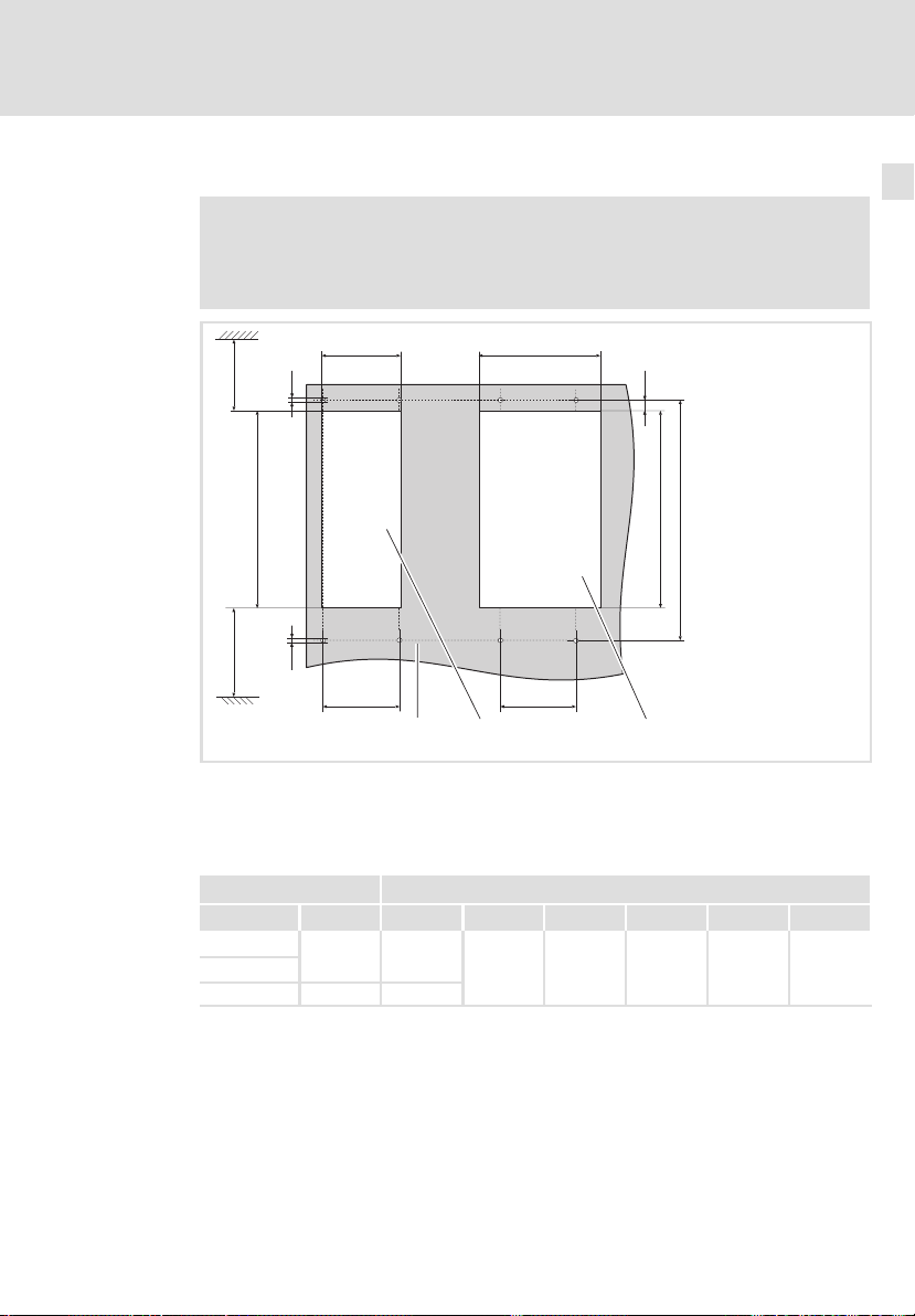
Abmessungen Einbauausschnitt
Hinweis!
Montage mit Schirmbefestigung ECSZS000X0B:
ƒ Einbaufreiraum unterhalb des Einbauausschnitts > 220 mm
a1 a1
g
³ 70 mm
3
Abmessungen
h
b1
g
³ 90 mm
c1
0
Abb. 3−2 Abmessungen Einbauausschnitt
Montagefläche
Einbauausschnitt für Baugröße
Einbauausschnitt für Baugröße
Versorgungsmodul Maße [mm]
Typ Baugröße a1 b1 c1 d g h
ECSDE012
ECSDE020
ECSDE040 121,5
78,5
c1
1
197 75 250 M5 10,5
b1
d
2
ECSXA063
EDKCSDE040 DE/EN/FR 4.0
25
Page 26

3
Mechanische Installation
Montage mit thermischer Separierung (Durchstoß−Technik)
Montageschritte
3.2.2 Montageschritte
So montieren Sie das Versorgungsmodul:
1. Befestigungsbohrungen für die Klemmbügel auf Montagefläche
vorbereiten.
– Dazu Bohrschablone anlegen.
2. Einbauausschnitt vorbereiten.
– Die Kanten des Einbauausschnitts und der Befestigungsbohrungen für
die Klemmbügel müssen leicht nach innen (zum Versorgungsmodul)
gewölbt sein.
3. Gewinde der Schrauben für die Klemmbügel mit flüssiger
Gewindedichtung bestreichen.
4. Klemmbügel befestigen.
5. Versorgungsmodul in den Einbauausschnitt schieben.
6. Versorgungsmodul in Klemmbügel oben und unten einrasten.
26
EDKCSDE040 DE/EN/FR 4.0
Page 27

Elektrische Installation
EMV−gerechte Installation (Aufbau des CE−typischen Antriebssystems)
4 Elektrische Installation
4.1 EMV−gerechte Installation (Aufbau des CE−typischen Antriebssystems)
Allgemeine Hinweise
ƒ Die elektromagnetische Verträglichkeit einer Maschine ist abhängig von
der Art und Sorgfalt der Installation. Beachten Sie besonders:
– Aufbau
– Filterung
– Schirmung
– Erdung
ƒ Bei abweichender Installation ist für die Bewertung der Konformität zur
EMV−Richtlinie die Überprüfung der Maschine oder Anlage auf Einhaltung
der EMV−Grenzwerte erforderlich. Dies gilt z. B. bei:
– Verwendung ungeschirmter Leitungen
– Verwendung von Sammel−Entstörfiltern anstelle der zugeordneten
Funk−Entstörfilter
– Betrieb ohne Funk−Entstörfilter
ƒ Die Verantwortung für die Einhaltung der EMV−Richtlinie in der
Maschinenanwendung liegt beim Weiterverwender.
– Wenn Sie die folgenden Maßnahmen beachten, können Sie davon
ausgehen, dass beim Betrieb der Maschine keine vom Antriebssystem
verursachten EMV−Probleme auftreten und die EMV−Richtlinie bzw. das
EMV−Gesetz erfüllt ist.
– Werden in der Nähe der ECS−Module Geräte betrieben, die der
CE−Anforderung hinsichtlich der Störfestigkeit EN 61000−6−2 nicht
genügen, können diese Geräte durch die ECS−Module
elektromagnetisch beeinträchtigt werden.
4
EDKCSDE040 DE/EN/FR 4.0
27
Page 28

4
Elektrische Installation
EMV−gerechte Installation (Aufbau des CE−typischen Antriebssystems)
Aufbau
ƒ ECS−Module, Funk−Entstörfilter und Netzdrossel großflächig mit geerdeter
Montageplatte verbinden:
– Montageplatten mit elektrisch leitender Oberfläche (verzinkt oder
rostfreier Stahl) erlauben eine dauerhafte Verbindung.
– Lackierte Platten sind nicht geeignet für die EMV−gerechte Installation.
ƒ Verwendung des Kondensatormoduls ECSxK...:
– Installieren Sie das Kondensatormodul zwischen dem
Versorgungsmodul und dem/den Achsmodul(en).
– Ist die Gesamtleitungslänge im Zwischenkreisverbund > 5 m,
installieren Sie das Kondensatormodul möglichst nah am Achsmodul
mit der größten Leistung.
ƒ Verwendung mehrerer Montageplatten:
– Montageplatten großflächig leitend miteinander verbinden (z. B. mit
Kupferbändern).
ƒ Beim Verlegen der Leitungen auf räumliche Trennung der Motorleitung
von Signal− und Netzleitungen achten.
ƒ Eine gemeinsame Klemmen−/Steckerleiste für Netzeingang und
Motorausgang vermeiden.
ƒ Leitungsführung möglichst dicht am Bezugspotenzial. Frei schwebende
Leitungen wirken wie Antennen.
Filterung
Verwenden Sie nur die den Versorgungssmodulen zugeordneten Funk−Entstörfilter und Netzdrosseln:
ƒ Funk−Entstörfilter reduzieren unzulässige hochfrequente Störgrößen auf
ein zulässiges Maß.
ƒ Netzdrosseln reduzieren niederfrequente Störgrößen, die insbesondere
durch die Motorleitungen bedingt werden und von deren Länge abhängig
sind.
28
EDKCSDE040 DE/EN/FR 4.0
Page 29

Elektrische Installation
EMV−gerechte Installation (Aufbau des CE−typischen Antriebssystems)
Schirmung
ƒ Am Achsmodul den Schirm der Motorleitung
– mit der Schirmbefestigung ECSZS000X0B auflegen.
– großflächig mit der Montageplatte unterhalb des Achsmoduls
verbinden.
– Empfehlung: Schirm mit Erdungsschellen auf metallisch blanken
Montageflächen ausführen.
ƒ Bei Schützen, Motorschutzschalter oder Klemmen in der Motorleitung:
– Die Schirme der dort angeschlossenen Leitungen miteinander
verbinden und ebenfalls großflächig mit der Montageplatte
kontaktieren.
ƒ Im Klemmenkasten des Motors oder am Motorgehäuse den Schirm
großflächig mit PE verbinden:
– Metallische Kabelverschraubungen am Motorklemmkasten
gewährleisten eine großflächige Verbindung des Schirms mit dem
Motorgehäuse.
ƒ UG−Leitungen und Steuerleitungen ab 0,3 m Länge abschirmen:
– Schirme digitaler Steuerleitungen beidseitig auflegen.
– Schirme analoger Steuerleitungen einseitig auflegen.
– Schirme auf kürzestem Weg mit den Schirmanschlüssen am Achsmodul
verbinden.
ƒ Einsatz der ECS−Module in Wohngebieten:
– Zur Begrenzung der Störstrahlung zusätzliche Schirmdämpfung ³ 10 dB
vorsehen. Diese wird in der Regel durch Einbau in handelsübliche,
geschlossene, metallische und geerdete Schaltschränke oder −kästen
erreicht.
Erdung
ƒ Alle metallisch leitfähigen Komponenten (z. B. ECS−Module,
Funk−Entstörfilter, Motorfilter, Netzdrosseln) durch entsprechende
Leitungen von einem zentralen Erdungspunkt (PE−Schiene) erden.
ƒ Die in den Sicherheitsvorschriften definierten Mindestquerschnitte
einhalten:
– Für die EMV ist nicht der Leitungsquerschnitt, sondern die Oberfläche
der Leitung und der flächigen Kontaktierung entscheidend.
4
EDKCSDE040 DE/EN/FR 4.0
29
Page 30
4
Elektrische Installation
Antriebssystem am Netz
Potenzialtrennung
4.2 Antriebssystem am Netz
Diese Informationen gelten für das ECS−Antriebssystem, bestehend aus:
ƒ Versorgungsmodul ECSxE...
ƒ Kondensatormodul ECSxK... (optional)
ƒ Achsmodul ECSxS/P/M/A...
ƒ Motor
ƒ Zubehör
ƒ Verdrahtung
4.2.1 Potenzialtrennung
Die integrierte Potenzialtrennung zwischen dem Leistungsteil und dem Steuerteil ist eine Schutztrennung (verstärkte Isolierung) nach EN 61800−5−1.
Zur Aufrechterhaltung dieser Schutztrennung muss gewährleistet sein, dass die
externe 24 V−Versorgung und alle daran angeschlossenen Komponenten ebenfalls eine Schutztrennung (SELV/PELV) nach EN 61800−5−1 aufweisen.
24 V−Teil DC−Zwischenkreis
X6/+24, GND X22
Dig. Eingang/Ausgang
X6/DI1, DI2, D24, DO1
Temperaturschalter
X6/T1, T2
Basisisolierung
(50 V)
Verstärkte Isolierung
(300 V)
30
CAN
X4 Netz
AIF
X1
Abb. 4−1 Potenzialtrennung
X21
EDKCSDE040 DE/EN/FR 4.0
Page 31

4.2.2 Netzformen / Netzbedingungen
Stop!
Das Versorgungsmodul ist ausschließlich für den Betrieb an
symmetrischen Netzen zugelassen. Ein Betrieb an
Außenleiter−geerdeten Netzen ist nicht zulässig.
Die Versorgungsmodule ECSxE... sind mit einer automatischen Erkennung der
Netzspannung mit Anpassung der Brems−Chopper Einschaltspannung ausgestattet.
Beachten Sie die Einschränkungen bei den jeweiligen Netzformen:
Netz Betrieb der Versorgungsmodule Bemerkungen
mit geerdetem
Sternpunkt (TT/
TN−Netze)
mit isoliertem
Sternpunkt (IT−
Netze)
uneingeschränkt erlaubt Bemessungsdaten der Versorgungs-
Einsatz der IT−Variante ECSxExxxx4I
ist möglich, wenn bei einem Erdschluss im speisenden Netz das Versorgungsmodul geschützt ist:
l durch geeignete Einrichtungen, die
den Erdschluss erfassen.
l das Versorgungsmodul unmittel-
bar vom Netz getrennt wird.
Elektrische Installation
Antriebssystem am Netz
Netzformen / Netzbedingungen
module einhalten.
Bei Erdschluss am Ausgang des Versorgungsmoduls ist der sichere Betrieb nicht gewährleistet.
4
Hinweis!
EDKCSDE040 DE/EN/FR 4.0
ƒ Netzspannungseinbrüche können Sie vermindern durch
Verringern der maximalen Ladestromgrenze (C0022).
ƒ Deaktivieren Sie die Ladestrombegrenzung (Laderelais) der
angeschlossenen ECS−Achsmodule mit C0175 = 3.
31
Page 32

4
4.2.3 Betrieb an öffentlichen Netzen (Einhaltung der EN 61000−3−2)
Elektrische Installation
Antriebssystem am Netz
Betrieb an öffentlichen Netzen (Einhaltung der EN 61000−3−2)
In der Europäischen Norm EN 61000−3−2 sind Grenzwerte zur Begrenzung von
Oberschwingungsströmen im Versorgungsnetz festgelegt. Nicht lineare Verbraucher (z. B. Frequenzumrichter) erzeugen Oberschwingungsströme, die das
speisende Netz "verunreinigen" und daher andere Verbraucher stören können.
Ziel der Norm ist es, die Qualität öffentlicher Versorgungsnetze zu sichern und
die Netzbelastung zu reduzieren.
Hinweis!
Die Norm gilt nur für öffentliche Netze. Netze mit eigener
Trafostation, die in Industriebetrieben üblich sind, sind nicht
öffentlich und fallen nicht in den Anwendungsbereich der Norm.
Besteht ein Gerät oder eine Maschine aus mehreren Komponenten,
werden die Grenzwerte der Norm auf die gesamte Einheit
angewendet.
32
EDKCSDE040 DE/EN/FR 4.0
Page 33

4.3 Leistungsanschlüsse
Gefahr!
Gefährliche elektrische Spannung
Der Ableitstrom gegen Erde (PE) ist > 3.5 mA AC bzw. > 10 mA DC.
Mögliche Folgen:
ƒ Tod oder schwere Verletzungen beim Berühren des Gerätes im
Fehlerfall.
Schutzmaßnahmen:
ƒ Die in der EN 61800−5−1 geforderten Maßnahmen umsetzen.
Insbesondere:
– Festinstallation
– PE−Anschluss normgerecht ausführen (PE−Leiterdurchmesser
³ 10 mm
Elektrische Installation
Leistungsanschlüsse
2
oder PE−Leiter doppelt auflegen)
4
Stop!
Kein Geräteschutz gegen zu hohe Netzspannung
Der Netzeingang ist intern nicht abgesichert.
Mögliche Folgen:
ƒ Zerstörung des Gerätes bei zu hoher Netzspannung.
Schutzmaßnahmen:
ƒ Beachten Sie die maximal zulässige Netzspannung.
ƒ Sichern Sie das Gerät netzseitig fachgerecht gegen
Netzschwankungen und Spannungsspitzen ab.
ƒ Alle Leistungsanschlüsse sind steckbar ausgeführt und kodiert. Das
Steckverbinder−Set für Versorgungsmodule ECSZE000X0B muss gesondert
bezogen werden.
ƒ Installation der Leitungen nach EN 60204−1.
ƒ Die verwendeten Leitungen müssen den geforderten Approbationen am
Einsatzort entsprechen (z. B. VDE, UL usw.).
EDKCSDE040 DE/EN/FR 4.0
33
Page 34

4
Elektrische Installation
Leistungsanschlüsse
Belegung der Steckerleisten
Klemme Funktion Elektrische Daten
X21 Anschluss Netz
X21/L1 Netzphase L1
X21/L2
X21/L3 Netzphase L3
X21/PE Anschluss PE−Leiter
X22 Anschluss DC−Zwischenkreisspannung
X22/BR0
X22/BR1
X22/+UG
X22/+UG
X22/−UG
X22/PE
Netzphase L2
Interner Bremswiderstand, Anschluss 1
Externer Bremswiderstand, Anschluss 1
Interner/Externer Bremswiderstand, An-
schluss 2
Einspeisung Zwischenkreisspannung, plus
Einspeisung Zwischenkreisspannung, minus
Anschluss PE−Leiter
anwendungs− und typabhängig
0 ... 480 V
bis 31,3 A (
anwendungs− und typabhängig
0 ... 770 V
bis 38,5 A (
19)
19)
Leitungsquerschnitte und Schraubenanzugsmomente
Leitungstyp
Klemmenleiste X21 und X22
starr ˘
flexibel
Aderendhülse Mögliche Leitungs-
ohne Aderendhülse
mit Aderendhülse
isoliert
mit TWIN−Aderendhülse isoliert
querschnitte
0,2 ... 10 mm
(AWG 24 ... 8)
0,2 ... 10 mm
(AWG 24 ... 8)
0,25 ... 6 mm
(AWG 22 ... 10)
0,25 ... 4 mm
(AWG 22 ... 12)
2
2
2
2
Anzugsmoment Abisolierlänge
5 mm bei Schraub-
1,2 ... 1,5 Nm
(10.6 ... 13.3 lb−in)
anschluss
10 mm bei Federkraftanschluss
Geschirmte Leitungen
Folgende Faktoren bestimmen maßgeblich die Wirkung der geschirmten Leitungen:
ƒ Gute Schirmanbindung
– Schirm großflächig auflegen
ƒ Niedriger Schirmwiderstand
– Nur Schirme mit verzinntem oder vernickeltem Kupfergeflecht
verwenden (Schirme aus Stahlgeflecht sind ungeeignet).
ƒ Hoher Überdeckungsgrad des Schirmgeflechts
– Mindestens 70 ... 80 % mit 90° Überdeckungswinkel
Klemmbügel und Schirmblech enthält die Schirmbefestigung ECSZS000X0B.
34
EDKCSDE040 DE/EN/FR 4.0
Page 35

Elektrische Installation
Leistungsanschlüsse
Netzanschluss
4
4.3.1 Netzanschluss
Wichtige Hinweise
ƒ Leitungen zwischen Funk−Entstörfilter und Versorgungsmodul möglichst
kurz ausführen.
– Auf kurzschlusssichere Verlegung achten!
ƒ Netzleitungen und ±U
ƒ Bei paralleler Verlegung der Netzleitungen und ±U
– Leitungsabstand: > 150 mm
ƒ Leitungslänge > 30 cm:
– Leitungen zwischen Funk−Entstörfilter und Versorgungsmodul nach der
allgemeinen EMV−Richtlinie geschirmt verlegen.
ƒ Bei einigen 24 V−Schaltnetzteilen werden die EMV−Grenzwerte für die
Installation nur eingehalten, wenn Sie diese am Funk−Entstörfilter
ECSZZ... anschließen. Zur Einhaltung von EMV−Grenzwerten für
leitungsgebundene Störungen halten Sie Rücksprache mit dem Hersteller
des Netzteils.
Dokumentation zum Funk−Entstörfilter ECSZZ...
Beachten Sie die enthaltenen Hinweise.
−Leitungen dürfen sich nicht berühren.
G
−Leitungen:
G
EDKCSDE040 DE/EN/FR 4.0
35
Page 36

4
Elektrische Installation
Leistungsanschlüsse
Netzanschluss
Verdrahtungsvarianten beim Versorgungsmodul ECSxE
3
44
1
00
3
Abb. 4−2 Verdrahtungsvarianten beim Versorgungsmodul ECSxE
Einfache Verdrahtung
/ Verdrahtung mit Netzdrosseln
Verdrahtung mit Funk−Entstörfiltern
Versorgungsmodul ECSxE
Netzdrossel
Funk−Entstörfilter
Komponentenverdrahtung
Netzleitung
4
4
02
2
0
3
3
4
1
02
3
ECSXE040
36
EDKCSDE040 DE/EN/FR 4.0
Page 37

Elektrische Installation
Leistungsanschlüsse
Netzanschluss
Sicherungen
Verwenden Sie zum Schutz der Netzleitung folgende Leitungsschutzschalter
oder UL−approbierte Schmelzsicherungen (siehe dazu Abb. 4−2 ( 36)):
4
Versorgungs-
modul
ECSxE012 C16 A 2,5 25 A 12
ECSxE020 C16 A 2,5 25 A 12
ECSxE040
: C 40 A 10
/: , C 32 A 6 35 A 10
: C 40 A 6
: C 40 A 10 35 A 8
1) Leitung ohne Aderendhülse oder mit Stiftkabelschuh
2) Leitungslänge max. 30 cm
Auslegung nach IEC/EN Auslegung nach UL
Leitungsschutz-
schalter
Leitungsquer-
schnitt
2
]
[mm
1)
2)
UL−Sicherung AWG
35 A 8
35 A 10
Warnings!
ƒ Nur UL−approbierte Leitungen, Sicherungen und Sicherungshalter
verwenden.
ƒ UL−Sicherung:
– Spannung 500 ... 600 V
– Auslösecharakteristik "H", "K5" oder "CC"
Defekte Sicherungen auswechseln
Gefahr!
Gefährliche elektrische Spannung
Bauteile können bis zu 3 Minuten nach Netz−Ausschalten
gefährliche Spannung führen.
Mögliche Folgen:
ƒ Tod oder schwere Verletzungen beim Berühren des Gerätes.
Schutzmaßnahmen:
ƒ Defekte Sicherungen nur im spannungslosen Zustand
auswechseln.
– Im Verbundbetrieb bei allen Achsmodulen Reglersperre (CINH)
setzen und alle Versorgungsmodule vom Netz trennen.
1)
2)
EDKCSDE040 DE/EN/FR 4.0
37
Page 38

4
Elektrische Installation
Leistungsanschlüsse
Anschluss an den DC−Zwischenkreis (+U
, −UG)
G
4.3.2 Anschluss an den DC−Zwischenkreis (+UG, −UG)
Stop!
ƒ Die Versorgung von Lenze−Geräten der Reihen 82xx und 93xx ist
nicht zulässig.
ƒ Bei der Verwendung von Synchron−Motoren mit hoher
Schwungmasse kann eine erhebliche Energiemenge in den
Zwischenkreis zurückgespeist werden. Beachten Sie dies bei der
Dimensionierung des Bremswiderstandes.
ƒ Bei einer Gesamtleitungslänge > 20 m installieren Sie ein Achsmodul oder
ein Kondensatormodul direkt am Versorgungsmodul.
ƒ ±U
−Leitungen verdrillt und möglichst kurz ausführen. Auf
G
kurzschlusssichere Verlegung achten!
ƒ Leitungslänge (Modul « Modul) > 30 cm: ±U
verlegen.
Dokumentationen der Achsmodule ECSxS/P/M/A
Beachten Sie die enthaltenen Hinweise.
Dokumentation des Kondensatormoduls ECSxK
Beachten Sie die enthaltenen Hinweise.
Sicherungen
Eine Absicherung des Zwischenkreisverbundes ist bei Verwendung netzseitig
abgesicherter Versorgungsmodule der Reihe ECS ist nicht erforderlich.
Leitungsquerschnitt
−Leitungen geschirmt
G
38
Leitungslänge (Modul−Modul)
bis 20 m
> 20 m
Aderendhülse Leitungsquer-
ohne Aderendhülse
mit Aderendhülse
isoliert
ohne Aderendhülse
mit Aderendhülse
isoliert
Bei Verdrahtung
Stiftkabelschuhe
verwenden!
schnitt
(AWG 10)
(AWG 8)
6 mm
10 mm
2
Anzugsmoment Abisolierlänge
1,2 ... 1,5 Nm
(10.6 ... 13.3 lb−in)
2
EDKCSDE040 DE/EN/FR 4.0
5 mm bei Schraubanschluss
10 mm bei Federkraftanschluss
Page 39

Elektrische Installation
Leistungsanschlüsse
Anschlussplan für die Mindestverdrahtung mit internem Bremswiderstand
4
4.3.3 Anschlussplan für die Mindestverdrahtung mit internem Bremswiderstand
Stop!
ECS−Versorgungsmodule immer mit einem Bremswiderstand
(intern/extern) betreiben.
Die ECS−Versorgungsmodule in den Ausführungen Standard−Einbaugerät und
Durchstoß−Technik (ECSEE / ECSDE) verfügen über einen Geräte−internen
Bremswiderstand.
Zur Nutzung des internen Bremswiderstandes (Rb) nehmen Sie folgende Verdrahtung vor:
ƒ Brücke zwischen Klemmen X22/+UG und X22/BR0 (CR)
Stromfluss von +UG über den internen Bremswiderstand (Rb) und den
Bremstransistor nach −UG.
ƒ Brücke zwischen Klemmen X6/T1 und X6/T2 (CR)
Temperatur−Überwachung des nicht vorhandenen externen Bremswiderstandes deaktivieren.
EDKCSDE040 DE/EN/FR 4.0
39
Page 40

4
Elektrische Installation
Leistungsanschlüsse
Anschlussplan für die Mindestverdrahtung mit internem Bremswiderstand
K1
L1
L2
L3
N
F1...F3
F4
Z1
Off
On
K1
K1
"
"
L1 L2
ECSEE...
ECSDE...
L3
PE
BR0
BR1
X21
Rb
X6
...
T1
T2
PE
+UG
+UG
-UG
X22
+UG
-UG
-UG
+UG
X23
ECSxS/P/M/A...
X24
X25
BD2
BD1
UV
"
"
M
3~
+
Abb. 4−3 Leistungsverbund mit internem Bremswiderstand
HF−Schirmabschluss durch großflächige Anbindung an Funktionserde (siehe
K1 Netzschütz
F1 ... F4 Sicherung
Z1 Netzdrossel / Netzfilter, optional
Rb Interner Bremswiderstand
J KTY−Temperatursensor des Motors
Systemleitung − Rückführung
Montageanleitung Schirmbefestigung ECSZS000X0B)
verdrillte Leitungen
PE
PE
+UG
+UG
PE
-UG
PE
-UG
X23
ECSxS/P/M/A...
X7
X25
BD2
PE
W
BD1
UV
0
"
"
"
"
6
R
J
2
+
M
3~
X7
X24
PE
W
0
"
"
6
R
J
2
ECSXA011
40
EDKCSDE040 DE/EN/FR 4.0
Page 41

Elektrische Installation
Leistungsanschlüsse
Anschlussplan für die Mindestverdrahtung mit externem Bremswiderstand
4.3.4 Anschlussplan für die Mindestverdrahtung mit externem Bremswiderstand
Stop!
ƒ ECS−Versorgungsmodule immer mit einem Bremswiderstand
betreiben.
ƒ Eine parallele Verdrahtung von internem und externem
Bremswiderstand ist nicht zulässig!
ƒ Den Thermokontakt des Bremswiderstands so in die
Anlagenüberwachung einbinden, dass bei Überhitzung des
Bremswiderstands die Netzversorgung des Versorgungsmoduls
abgeschaltet wird.
ƒ Lesen Sie die Dokumentation zum externen Bremswiderstand.
Beachten Sie die enthaltenen Sicherheitshinweise.
Wenn beim Versorgungsmodul in der Ausführung Standard−Einbaugerät oder
Durchstoß−Technik (ECSEE / ECSDE) ein hoher Bremsleistungsbedarf besteht,
kann anstelle des internen Bremswiderstandes ein externer leistungsstärkerer
Bremswiderstand angeschlossen werden.
Ein Versorgungsmodul in Cold−Plate−Technik (ECSCE) verfügt Bauart−bedingt
über keinen internen Bremswiderstand, so dass bei dieser Gerätevariante immer ein externer Bremswiderstand (Rbext) angeschlossen werden muss.
ƒ Bremswiderstand an X22/BR1 und X22/+UG anschließen.
ƒ Den Thermokontakt (Öffner) des externen Bremswiderstandes an X6/T1
und X6/T2 anschließen.
4
EDKCSDE040 DE/EN/FR 4.0
41
Page 42

4
Elektrische Installation
Leistungsanschlüsse
Anschlussplan für die Mindestverdrahtung mit externem Bremswiderstand
K1
L1
L2
L3
N
F1...F3
F4
Z1
Rb
ext
J
"
Off
K1
"
L3
PE
BR0
On
L1 L2
BR1
X21
ECSxE...
X6
...
T1
K1
T2
J
(Rb
)
ext
PE
+UG
+UG
-UG
+UG
X22
ECSxS/P/M/A...
BD1
"
+UG
PE
-UG
PE
-UG
X23
+UG
+UG
PE
-UG
PE
-UG
X23
ECSxS/P/M/A...
X24
X25
BD2
UV
X7
PE
W
X24
X25
BD2
BD1
UV
0
"
"
X7
PE
W
0
"
"
M
3~
+
Abb. 4−4 Leistungsverbund mit externem Bremswiderstand
HF−Schirmabschluss durch großflächige Anbindung an Funktionserde (siehe
K1 Netzschütz
F1 ... F4 Sicherung
Z1 Netzdrossel / Netzfilter, optional
Rb
J KTY−Temperatursensor des Motors
Systemleitung − Rückführung
Montageanleitung Schirmbefestigung ECSZS000X0B)
verdrillte Leitungen
Externer Bremswiderstand
ext
"
"
6
R
J
2
+
"
J
2
ECSXA012
6
R
M
3~
42
EDKCSDE040 DE/EN/FR 4.0
Page 43

Elektrische Installation
Leistungsanschlüsse
Anschlussplan für die Mindestverdrahtung mit externem Bremswiderstand
Verdrahtung externer Bremswiderstand ERBM...
4
ERBM...
R
B_ext
PE
R
B_ext
"
< 0.5 m
"
BR0
BR1
X22
+UG
+UG
-UG
PE
T2
T1
X6
BR0
BR1
X22
+UG
+UG
…
ECSCE...
Abb. 4−5 Anschluss externe Bremswiderstände, Reihe ERBM...
HF−Schirmabschluss durch großflächige PE−Anbindung
verdrillte Leitungen
Verdrahtung externer Bremswiderstand ERBS.../ERBD...
ERBS... / ERBD...
R
B
RB1 RB2 T1 T2
PE
"
ERBS... / ERBD...
R
B
RB1 RB2 T1 T2
ERBM...
PE
-UG
PE
PE
T1
X6
ECSCE...
T2
ECSXE011
<10cm
<5m
…
BR0
BR1
Abb. 4−6 Verdrahtung externer Bremswiderstand, Reihe ERBS.../ERBD...
EDKCSDE040 DE/EN/FR 4.0
X22
< 0.5 m
<5m
"
+UG
+UG -UG
PE
…
T2
T1
X6
BR0
BR1
X22
+UG
+UG -UG
PE
ECSxE...
HF−Schirmabschluss durch großflächige PE−Anbindung
verdrillte Leitungen
T1
ECSxE...
T2
X6
…
ECSXE010
43
Page 44

4
Elektrische Installation
Leistungsanschlüsse
Anschluss eines Kondensatormoduls ECSxK... (optional)
4.3.5 Anschluss eines Kondensatormoduls ECSxK... (optional)
Die ECS−Kondensatormodule stützen die Zwischenkreisspannung für das Antriebssystem. Diese Kondensatormodul−Typen sind erhältlich:
ƒ ECSxK001 (705 mF, ±20 %)
ƒ ECSxK002 (1410 mF, ±20 %)
x Bauform/Montage−Technik: E = Standard−Einbau
C = Cold−Plate−Technik
D = Durchstoß−Technik
Dokumentation des Kondensatormoduls ECSxK
Beachten Sie die enthaltenen Hinweise.
44
EDKCSDE040 DE/EN/FR 4.0
Page 45

Elektrische Installation
4
Leistungsanschlüsse
Anschluss eines Kondensatormoduls ECSxK... (optional)
K1
L1
L2
L3
N
F1...F3
F4
Z1
Off
On
K1
"
"
L1 L2
L3
PE
BR0
X21
BR1
PE
+UG
-UG
+UG
X22
ECSxE...
K1
X6
DI2
DO1
D24
T1
T2
DI1
+24V
GND
"
"
0
GND
-
+
24VDC
Abb. 4−7 Verdrahtung Kondensatormodul ECSxK...
HF−Schirmabschluss durch großflächige Anbindung an Funktionserde (siehe
K1 Netzschütz
F1 ... F4 Sicherung
Z1 Netzdrossel / Netzfilter, optional
Hilfsschütz
Systemleitung ˘ Rückführung
Klemme X6/SI1 der angeschlossenen Achsmodule (Reglerfreigabe/−sperre)
Montageanleitung Schirmbefestigung ECSZS000X0B)
verdrillte Leitungen
+UG
+UG
-UG
PE
-UG
X23
ECSxK...
-UG
-UG
+UG
PE
+UG
PE
PE
X23
ECSxS/P/M/A...
X24
X25
X26
BD2
BD1
UV
"
"
M
3~
+
2
X7
PE
W
1
"
"
6
R
J
2
ECSXX004
EDKCSDE040 DE/EN/FR 4.0
45
Page 46

4
4.4 Steueranschlüsse
Elektrische Installation
Steueranschlüsse
ƒ Für die Versorgung der Steuerelektronik ist eine externe
24 V−Gleichspannung an den Klemmen X6/+24 und X6/GND erforderlich.
ƒ An die Klemmen X6/T1 und X6/T2 schließen Sie den Temperaturfühler
eines externen Bremswiderstandes an. Wird kein externer
Bremswiderstand benötigt, brücken Sie die Klemmen X6/T1 und X6/T2.
Stop!
ƒ Führen Sie die Steuerleitungen immer geschirmt aus, um
Störeinkopplungen zu vermeiden.
ƒ Die Spannungsdifferenz zwischen X6/AG, X6/GND und dem PE
des Achsmoduls darf maximal 50 V betragen.
ƒ Die Spannungsdifferenz begrenzen Sie durch:
– überspannungsbegrenzende Bauelemente oder
– direkte Anbindung von X6/AG und X6/GND mit PE.
ƒ Die Verschaltung muss sicherstellen, dass bei X6/DO1 = 0
(LOW−Pegel) die angeschlossenen Achsmodule keine Energie aus
dem Zwischenkreis entnehmen. Sonst kann das
Versorgungsmodul beschädigt werden.
Schirmauflage der Steuerleitungen und Signalleitungen
Das Blech auf der Gerätevorderseite dient als Montagestelle (zwei Gewindebohrungen M4) für die Schirmauflage der Signalleitungen. Die verwendeten
Schrauben dürfen max. 10 mm in den Innenraum des Gerätes hineinragen. Für
eine optimale Kontaktierung der Schirmauflage verwenden Sie die Klemmbügel der Schirmbefestigung ECSZS000X0B.
46
EDKCSDE040 DE/EN/FR 4.0
Page 47

L1 L2
X21
Elektrische Installation
4
Steueranschlüsse
+UG
L3
PE
BR0
BR1
X22
+UG
-UG
PE
+UG
+UG
X23
-UG-UG
PEPE
"
"
0
T1
T2
ECSxE...
X6
DI1
DI2
DO1
D24
+24V
GND
1
+24 VDC
GND
ECSxS/P/M/A...
DI1
DI2
DI3
DO1
DI4
"
"
Abb. 4−8 Verbund: Steuersignale mit internem Bremswiderstand
HF−Schirmabschluss durch großflächige Anbindung an Funktionserde (siehe
Montageanleitung Schirmbefestigung ECSZS000X0B)
/ Hilfsschütz/−relais
Spannungsversorgung Motorhaltebremse 23 ... 30 V DC, max. 1,5 A
Sicher abgeschaltetes Moment (ehem. "Sicherer Halt")
Reglerfreigabe/−sperre
X6
AI-
AI+
=
+
24 VDC
GND
S24
"
"
SI1
SO
SI2
"
F 1,6 A
U
2
AG
+24V
-
B-
B+
3
+
=
-
4
ECSXA013
EDKCSDE040 DE/EN/FR 4.0
47
Page 48

4
Elektrische Installation
Steueranschlüsse
Einschaltsequenz des Hilfsrelais
Stop!
Überlastung der Ladeschaltung im Versorgungsmodul
Die Reglerfreigabe der Achsen darf erst erfolgen, wenn der
Ladevorgang des DC−Zwischenkreises abgeschlossen ist und das
Versorgungsmodul somit betriebsbereit ist.
Mögliche Folgen:
ƒ Zerstörung des Versorgungsmoduls
Schutzmaßnahmen:
ƒ Nutzung der Schaltung zur zentralen Reglerfreigabe der Achsen
über die Ein− und Ausgänge DI2 und DO1 des
Versorgungsmodules (siehe nachfolgende Beschreibung).
Die Einschaltsequenz des Hilfsrelais (siehe Abb. 4−8) ist wie folgt:
1. Am Versorgungsmodul wird der Digitaleingang X6/DI1 (Netzfreigabe) von
der übergeordneten Steuerung oder vom Bediener auf HIGH geschaltet.
– Der DC−Zwischenkreis lädt auf.
2. Der Betriebsbereit−Ausgang des Achsmoduls (DO1) schaltet nun über
Relais den Digitaleingang X6/DI2 (zentrale Reglerfreigabe) des
Versorgungsmoduls.
– In den ECS−Achsmodulen ist in der Lenze−Werkseinstellung DO1 auf
"Betriebsbereit" eingestellt. "Betriebsbereit" steht erst an, wenn
mindestens eine bestimmte DC−Zwischenkreisspannung erreicht ist.
3. Über den Ausgang X6/DO1 des Versorgungsmodules erfolgt die zentrale
Reglerfreigabe für die Achsmodule. Die zentrale Reglerfreigabe DO1
schaltet erst, wenn der Ladevorgang des DC−Zwischenkreises
abgeschlossen ist UND der Eingang X6/DI2 gesetzt ist.
48
EDKCSDE040 DE/EN/FR 4.0
Page 49

Elektrische Installation
Steueranschlüsse
Belegung der Steckerleisten
Klemmenleiste X6
Ansicht Klemme Funktion Elektrische Daten
X6/+24 Niederspannungsversorgung
+24
T1 DO1 DI2 DI1
X6/GND Bezugspotenzial Niederspan-
T2 D24 GND
X6/T1 Temperaturschalter−Kontakt 1
X6/T2 Temperaturschalter−Kontakt 2
X6/D24 Niederspannungsversorgung
X6/DO1 Digitaler Ausgang 1
X6/DI1 Digitaler Eingang 1
X6/DI2 Digitaler Eingang 2
der Steuerelektronik
nungsversorgung
X6/DO1 (digitaler Ausgang 1)
(für zentrales Reglerfreigabe−Signal an angeschlossene Achsmodule)
(für Netzfreigabe/Laden des DC−
Zwischenkreises)
(für zentrales Reglerfreigabe−Signal von angeschlossenen Modulen; Ausgabe über Ausgang
X6/DO1)
Leitungsquerschnitte und Schraubenanzugsmomente
20 ... 30 V DC, 0,5 A (max. 1 A)
bei 24 V Einschaltstrom:
max. 2 A für 50 ms
18 ... 30 V DC
24 V DC, 0,7 A (max. 1,4 A)
kurzschlussfest
LOW:
−3 ... +5 V;
−3 ... +1,5 mA
HIGH:
+15 ... +30 V;
+2 ... +15 mA
Eingangsstrom bei 24 V DC:
8 mA pro Eingang
4
Leitungstyp
flexibel
Wir empfehlen Steuerleitungen mit einem Leitungsquerschnitt von 0,25 mm
zu verwenden.
EDKCSDE040 DE/EN/FR 4.0
Aderendhülse Leitungsquer-
ohne Aderendhülse
mit Aderendhülse
isoliert
schnitt
0,08 ... 1,5 mm
(AWG 28 ... 16)
0,25 ... 0,5 mm
(AWG 22 ... 20)
Anzugsmoment Abisolierlänge
2
0,22 ... 0,25 Nm
(1.95 ... 2.2 lb−in)
2
5 mm bei Schraubanschluss
9 mm bei Federkraftanschluss
2
49
Page 50

4
4.4.1 Digitale Eingänge und Ausgänge
Elektrische Installation
Steueranschlüsse
Digitale Eingänge und Ausgänge
Stop!
Bei Anschluss induktiver Last an X6/DO1 ein Funkenlöschglied mit
einer Begrenzungsfunktion auf max. 50 V ± 0 % vorsehen.
X6/DI1 − Netzfreigabe des Versorgungsmodules
ƒ Über den Eingang X6/DI1 wird das gesteuerte Aufladen des
DC−Zwischenkreises mittels Lade−Thyristor eingeleitet.
ƒ Erst nach abgeschlossener Aufladung, signalisiert durch die
Betriebsbereit−Meldung am Ausgang X6/DO1 des Versorgungsmoduls,
dürfen die angeschlossenen Achsmodule freigegeben werden, da sonst
der Lade−Thyristor überlastet werden kann.
X6/DI2 − zentrale Reglerfreigabe für die angeschlossenen Achsmodule über
DO1
ƒ Der Eingang X6/DI2 kann zusammen mit dem Ausgang X6/DO1 als
zentral gesteuerte Reglerfreigabe für alle angeschlossenen Achsen
verwendet werden. Der Ausgang DO1 schaltet erst, wenn die Aufladung
des DC−Zwischenkreises störungsfrei abgeschlossen worden ist. So wird
automatisch sicher gestellt, dass die Achsmodule nicht zu früh
freigegeben werden können und nicht zu früh Energie aus dem DC−Bus
entnehmen.
ƒ Verdrahten Sie dazu den Ausgang X6/DO1 des Versorgungsmoduls mit
den Eingängen X6/SI1 der Achsmodule für die Reglerfreigabe.
Ggf. kann für jedes Achsmodul noch ein weiterer Kontakt in Reihe geschaltet
werden, um die Achsmodule während des Betriebs auch einzeln sperren und
freigeben zu können.
ƒ Damit der Ausgang des Versorgungsmoduls X6/DO1 "HIGH" gesetzt wird,
müssen die folgenden Bedingungen erfüllt sein:
– Das Versorgungsmodul ist betriebsbereit.
– Der DC−Zwischenkreis ist aufgeladen.
– X6/DI1 = HIGH (der Reglerfreigabe−Eingang des Versorgungsmoduls ist
angesteuert)
– Der Ausgang X6/DO1 des Versorgungsmoduls benötigt die
24−V−Versorgungsspannung über Klemme X6/D24.
50
EDKCSDE040 DE/EN/FR 4.0
Page 51

4.5 Automatisierungs−Interface (AIF)
Auf das Automatisierungs−Interface (X1) können Sie das Keypad XT oder ein
Kommunikationsmodul stecken. Das Aufstecken und Abziehen ist auch während des Betriebs möglich.
ƒ Das Keypad XT dient zur Eingabe und Visualisierung von Parametern und
Codestellen.
ƒ Über Kommunikationsmodule können die Module des Servosystems ECS
mit dem Leitsystem (SPS oder PC) vernetzt werden.
Folgende Kombinationen sind möglich:
Elektrische Installation
Automatisierungs−Interface (AIF)
4
Bedien−/Kommunikationsmodul
Keypad XT EMZ9371BC ü ü
Handterminal
(Keypad XT mit Handheld)
LECOM−A (RS232) EMF2102IB−V004 ü ü
LECOM−B (RS485) EMF2102IB−V002 ü ü
LECOM−A/B
(RS232/485)
LECOM−LI (Lichtwellenleiter)
LON EMF2141IB − ü
INTERBUS EMF2113IB − ü
PROFIBUS−DP EMF2133IB − ü
CANopen EMF2178IB − ü
DeviceNet EMF2179IB − ü
EtherCAT EMF2192IB ü ü
Typ/Bestellnummer
E82ZBBXC ü ü
EMF2102IB−V001 ü ü
EMF2102IB−V003 ü ü
Verwendbar mit
ECSxE ECSxS/P/M/A
Kommunikationshandbücher zu den Kommunikationsmodulen
Hier finden Sie ausführliche Informationen zur Verdrahtung und
Anwendung der Kommunikationsmodule.
EDKCSDE040 DE/EN/FR 4.0
51
Page 52

4
4.6 Systembus (CAN) verdrahten
Elektrische Installation
Systembus (CAN) verdrahten
Über die Systembus−Schnittstelle (X4)
ƒ kommunizieren die Module der Reihe ECS.
ƒ kann parametriert oder Codestelleninhalt angezeigt werden.
Verdrahtung des Systembus(CAN)
52
Abb. 4−9 Beispiel zur Verdrahtung des Systembus (CAN)
ECSxE Versorgungsmodul
ECSxS/P/M/A Achsmodul
M Übergeordnete Steuerung, z. B. ETC
Hinweis!
Schließen Sie je einen Busabschluss−Widerstand (120 W) am ersten
und letzten Knoten des Systembus (CAN) an.
ECSxE092
EDKCSDE040 DE/EN/FR 4.0
Page 53

Elektrische Installation
Systembus (CAN) verdrahten
Belegung der Steckerleisten
X4 (CAN) X14 (CAN−AUX) Beschreibung
CH CAH CAN−HIGH
CL CAL CAN−LOW
CG CAG Bezugspotenzial
Spezifikation des Übertragungskabels
Wir empfehlen CAN−Kabel nach ISO 11898−2 zu verwenden:
CAN−Kabel nach ISO 11898−2
Kabeltyp Paarverseilt mit Abschirmung
Impedanz 120 W (95 ... 140 W)
Leitungswiderstand/−querschnitt
Kabellänge £ 300 m £ 70 mW/m / 0.25 0.34 mm2 (AWG22)
Kabellänge 301 1000 m £ 40 mW/m / 0.5 mm2 (AWG20)
Signallaufzeit £ 5 ns/m
4
EDKCSDE040 DE/EN/FR 4.0
53
Page 54

4
Elektrische Installation
Systembus (CAN) verdrahten
Busleitungslänge
Hinweis!
Halten Sie die zulässigen Leitungslängen unbedingt ein.
1. Überprüfen Sie die Einhaltung der Gesamt−Leitungslänge in Tab. 4−1.
Durch die Übertragungsrate ist die Gesamt−Leitungslänge festgelegt.
CAN−Übertragungsrate [kBit/s] Max. Buslänge [m]
50 1500
125 630
250 290
500 120
1000 25
Tab. 4−1 Gesamt−Leitungslänge
2. Überprüfen Sie die Einhaltung der Segment−Leitungslänge in Tab. 4−2.
Die Segment−Leitungslänge wird durch den verwendeten Leitungsquerschnitt
und die Teilnehmeranzahl festgelegt. Ohne Repeater ist die Segment−Leitungslänge gleich der Gesamt−Leitungslänge.
Anzahl Teilnehmer
2 240 m 430 m 650 m 940 m
5 230 m 420 m 640 m 920 m
10 230 m 410 m 620 m 900 m
20 210 m 390 m 580 m 850 m
32 200 m 360 m 550 m 800 m
63 170 m 310 m 470 m 690 m
Tab. 4−2 Segment−Leitungslänge
3. Vergleichen Sie die beiden ermittelten Werte miteinander.
Wenn der aus Tab. 4−2 ermittelte Wert kleiner als die zu realisierende Gesamt−
Leitungslänge aus Tab. 4−1 ist, müssen Repeater eingesetzt werden. Repeater
unterteilen die Gesamt−Leitungslänge in Segmente.
Leitungsquerschnitt
2
0,25 mm
0,5 mm
2
0,75 mm
2
1,0 mm
2
54
EDKCSDE040 DE/EN/FR 4.0
Page 55

Beispiel: Auswahlhilfe
Elektrische Installation
Systembus (CAN) verdrahten
4
Vorgaben
l Leitungsquerschnitt: 0,5 mm
l Teilnehmeranzahl: 63
l Repeater: Lenze−Repeater, Typ EMF2176IB (Leitungsreduzierung: 30 m)
2
(gemäß Kabel−Spezifikation 53 )
Bei max. Teilnehmeranzahl (63) sind aus den Vorgaben folgende Leitungslängen / Anzahl Repeater einzuhalten:
Übertragungsrate [kBit/s] 50 120 250 500 1000
Max. Leitungslänge [m] 1500 630 290 120 25
Segment−Leitungslänge [m] 310 310 290 120 25
Anzahl der Repeater 5 2 − − −
Repeater−Einsatz prüfen
Vorgaben
l Übertragungsrate: 125 kBit/s
l Leitungsquerschnitt: 0.5 mm
l Teilnehmeranzahl: 28
l Leitungslänge: 450 m
Prüfschritte Leitungslänge Siehe
1. Gesamt−Leitungslänge bei 125 kBit/s: 630 m Tab. 4−1
2. Segment−Leitungslänge für 28 Teilnehmer und einem Leitungsquerschnitt von 0.5 mm2:
3. Vergleich: Der Wert in Pkt. 2 ist kleiner als die zu realisierende Leitungslänge von 450 m.
2
360 m Tab. 4−2
Folgerung
l Ohne Repeater−Einsatz ist die zu realisierende Leitungslänge von 450 m nicht möglich.
l Es muss ein Repeater nach 360 m (Pkt. 2) eingesetzt werden.
EDKCSDE040 DE/EN/FR 4.0
55
Page 56

4
Elektrische Installation
Systembus (CAN) verdrahten
Ergebnis
l Verwendet wird der Lenze−Repeater, Typ EMF2176IB (Leitungsreduzierung: 30 m)
l Berechnung der max. Leitungslänge:
Erste Segment: 360
Zweite Segment: 360 m (entsprechend Tab. 4−1) minus 30 m (Leitungsreduzierung bei Einsatz
eines Repeaters)
à Max. erreichbare Leitungslänge mit einem Repeater: 690 m.
à Damit ist die vorgegebene Leitungslänge realisierbar.
Hinweis!
Die Verwendung eines weiteren Repeaters wird empfohlen als
ƒ Service−Schnittstelle
Vorteil: Ein störungsfreies Ankoppeln im laufenden Bus−Betrieb
ist möglich.
ƒ Einmess−Schnittstelle
Vorteil: Das Einmess−/Programmiergerät bleibt galvanisch
getrennt.
56
EDKCSDE040 DE/EN/FR 4.0
Page 57

5 Installation überprüfen
Überprüfen Sie nach Abschluss der Installation ...
ƒ die Verdrahtung auf Vollständigkeit, Kurzschluss und Erdschluss.
ƒ den Leistungsanschluss:
– Netzanschluss über Klemmen L1, L2, L3 (X21)
– Anschluss des Funk−Entstörfilters / der Netzdrossel
– Anschluss des Bremswiderstandes (intern/extern) über Klemmen BR0,
BR1 (X22)
– Polung der Einspeisung der Zwischenkreisspannung über Klemmen
+UG, −UG (X22)
ƒ Steueranschluss (X6):
– Einspeisung der 24 V−Versorgung, GND
– Temperaturfühler−Kontakt des externen Bremswiderstandes bzw.
Brücke bei Verwendung des internen Bremswiderstandes an den
Klemmen T1, T2.
– Verdrahtung angepasst an die Signalbelegung der Steuerklemmen.
ƒ die Kommunikation über Systembus (CAN).
Hinweis!
Der nächste Schritt ist die Inbetriebnahme. Informationen dazu
finden Sie in der ausführlichen Dokumentation des
Versorgungsmoduls.
ƒ Lesen sie die ausführliche Dokumentation, bevor Sie das
Versorgungsmodul einschalten!
ƒ Führen Sie die Inbetriebnahme nach den Anweisungen in der
ausführlichen Dokumentation durch!
Installation überprüfen 5
EDKCSDE040 DE/EN/FR 4.0
57
Page 58

Scope of supply
Position Description Number
Power supply module ECSDExxx 1
Accessory kit with attachment material 1
Mounting instructions 1
Drilling jig 1
Note!
The ECSZE000X0B connector set must be ordered separately.
Connections and interfaces
Position Description Detailed
X22 Connections
LEDs: Status and fault display
X1 Automation interface (AIF) for
X2 PE connection AIF
X3 Not assigned
X4 CAN connection
X6 Connections
S1 DIP switch
X21 Mains connection 88
l External brake resistor
l DC−bus voltage
l PE
l Communication module
l Operating module (XT keypad)
l System bus (CAN)
l Interface for
– master control and other modules
– PC/HMI for parameterisation and diagnostics
l Low−voltage supply
l Digital inputs and outputs
l Thermostat contacts
l CAN node address (device address in the CAN network)
l CAN baud rate
information
91
105
106
104
Status displays
LED
Red Green
Off On Power supply module is enabled, no fault
Off Blinking Power supply module is inhibited (CINH), switch−on inhibit
Blinking, 1 Hz Off Fault / error (TRIP) / short−circuit braking error (KSB−TRIP) is active
Blinking, 3 Hz Off Message active
Blinking, 1 Hz Blinking Warning active with inhibited module
Blinking, 1 Hz On Warning active with enabled module
Description
58
EDKCSDE040 DE/EN/FR 4.0
Page 59

These Operating Instructions are valid for ECSDE... power supply modules as of version:
ECS D E xxx x 4 x xxx XX xx xx
Device type
Design
E = standard panel−mounted unit, IP20
D = push−through technique (thermally
separated)
C = cold−plate technique
Rated current
012 = 12 A
020 = 20 A
040 = 38.5 A
Fieldbus interface
C = system bus CAN
ATTENTION
L ´appareil est sous tension
pendant 180s après la coupure
de la tension réseau
Voltage class
4 = 400 V/480 V
Technical version
B = standard
V = coated
Variant
Hardware version
VA or higher
Operating software version (B−SW)
1.2 or higher
WARNING
Device is live up to 180s
after removing
mains voltage
EDKCSDE040 DE/EN/FR 4.0
59
Page 60

Tip!
Information and auxiliary devices related to the Lenze products can be found in
the download area at
http://www.Lenze.com
0Fig. 0Tab. 0
© 2013 Lenze Automation GmbH, Postfach 10 13 52, D−31763 Hameln, Hans−Lenze−Str. 1, D−31855 Aerzen
No part of this documentation may be reproduced or made accessible to third parties without written consent by
Lenze Automation GmbH.
All information given in this documentation has been selected carefully and complies with the hardware and
software described. Nevertheless, discrepancies cannot be ruled out. We do not take any responsibility or liability
for any damage that may occur. Necessary corrections will be included in subsequent editions.
60
EDKCSDE040 DE/EN/FR 4.0
Page 61

Contents i
1 Safety instructions 62. . . . . . . . . . . . . . . . . . . . . . . . . . . . . . . . . . . . . . . . . . . . . . . .
1.1 General safety and application notes for
Lenze power supply modules 62. . . . . . . . . . . . . . . . . . . . . . . . . . . . . . . . .
1.2 Residual hazards 65. . . . . . . . . . . . . . . . . . . . . . . . . . . . . . . . . . . . . . . . . . . .
1.3 Safety instructions for the installation according to UL 67. . . . . . . . . . . .
1.4 Notes used 68. . . . . . . . . . . . . . . . . . . . . . . . . . . . . . . . . . . . . . . . . . . . . . . . .
2 Technical data 70. . . . . . . . . . . . . . . . . . . . . . . . . . . . . . . . . . . . . . . . . . . . . . . . . . . .
2.1 General data and operating conditions 70. . . . . . . . . . . . . . . . . . . . . . . .
2.2 Rated data 72. . . . . . . . . . . . . . . . . . . . . . . . . . . . . . . . . . . . . . . . . . . . . . . . .
2.3 External brake resistors 73. . . . . . . . . . . . . . . . . . . . . . . . . . . . . . . . . . . . . .
3 Mechanical installation 75. . . . . . . . . . . . . . . . . . . . . . . . . . . . . . . . . . . . . . . . . . . .
3.1 Important notes 75. . . . . . . . . . . . . . . . . . . . . . . . . . . . . . . . . . . . . . . . . . . .
3.2 Mounting with thermal separation (push−through technique) 76. . . . .
3.2.1 Dimensions 77. . . . . . . . . . . . . . . . . . . . . . . . . . . . . . . . . . . . . . .
3.2.2 Mounting steps 79. . . . . . . . . . . . . . . . . . . . . . . . . . . . . . . . . . .
4 Electrical installation 80. . . . . . . . . . . . . . . . . . . . . . . . . . . . . . . . . . . . . . . . . . . . . .
4.1 Installation according to EMC
(installation of a CE−typical drive system) 80. . . . . . . . . . . . . . . . . . . . . . .
4.2 Drive system on the mains 83. . . . . . . . . . . . . . . . . . . . . . . . . . . . . . . . . . .
4.2.1 Electrical isolation 83. . . . . . . . . . . . . . . . . . . . . . . . . . . . . . . . .
4.2.2 Supply forms / electrical supply conditions 84. . . . . . . . . . . .
4.2.3 Operation on public supply systems
(compliance with EN 61000−3−2) 85. . . . . . . . . . . . . . . . . . . . .
4.3 Power terminals 86. . . . . . . . . . . . . . . . . . . . . . . . . . . . . . . . . . . . . . . . . . . .
4.3.1 Mains connection 88. . . . . . . . . . . . . . . . . . . . . . . . . . . . . . . . . .
4.3.2 Connection to the DC bus (+UG, −UG) 91. . . . . . . . . . . . . . . . .
4.3.3 Connection plan for mimimum wiring with internal
brake resistor 93. . . . . . . . . . . . . . . . . . . . . . . . . . . . . . . . . . . . .
4.3.4 Connection plan for mimimum wiring with external
brake resistor 95. . . . . . . . . . . . . . . . . . . . . . . . . . . . . . . . . . . . .
4.3.5 Connection of an ECSxK... capacitor module
(optional) 98. . . . . . . . . . . . . . . . . . . . . . . . . . . . . . . . . . . . . . . .
4.4 Control terminals 100. . . . . . . . . . . . . . . . . . . . . . . . . . . . . . . . . . . . . . . . . . .
4.5 Automation interface (AIF) 105. . . . . . . . . . . . . . . . . . . . . . . . . . . . . . . . . . .
4.6 Wiring of system bus (CAN) 106. . . . . . . . . . . . . . . . . . . . . . . . . . . . . . . . . .
5 Installation check 111. . . . . . . . . . . . . . . . . . . . . . . . . . . . . . . . . . . . . . . . . . . . . . . . .
EDKCSDE040 DE/EN/FR 4.0
61
Page 62

1
Safety instructions
General safety and application notes for Lenze power supply modules
1 Safety instructions
1.1 General safety and application notes for Lenze power supply modules
(acc. to Low−Voltage Directive 2006/95/EC)
For your personal safety
Disregarding the following basic safety measures may lead to severe personal
injury and damage to material assets!
ƒ Only use the product as directed.
ƒ Never commission the product in the event of visible damage.
ƒ Never commission the product before assembly has been completed.
ƒ Do not carry out any technical changes on the product.
ƒ Only use the accessories approved for the product.
ƒ Only use original spare parts from Lenze.
ƒ Observe all regulations for the prevention of accidents, directives and
laws applicable on site.
ƒ Transport, installation, commissioning and maintenance work must only
be carried out by qualified personnel.
– IEC 364 and CENELEC HD 384 or DIN VDE 0100 and IEC−Report 664 or
DIN VDE 0110 and national regulations for the prevention of accidents
must be observed.
– According to the basic safety information, qualified, skilled personnel
are persons who are familiar with the assembly, installation,
commissioning, and operation of the product and who have the
qualifications necessary for their occupation.
ƒ Observe all specifications in this documentation.
– This is the condition for safe and troublefree operation and the
achievement of the specified product features.
– The procedural notes and circuit details described in this
documentation are only proposals. It is up to the user to check whether
they can be transferred to the particular applications. Lenze
Automation GmbH does not accept any liability for the suitability of the
procedures and circuit proposals described.
ƒ Depending on their degree of protection, Lenze power supply modules
and their accessory components can be live during operation. Surfaces
can be hot.
– Non−authorised removal of the required cover, inappropriate use,
incorrect installation or operation, creates the risk of severe injury to
persons or damage to material assets.
– For more information please see the documentation.
62
EDKCSDE040 DE/EN/FR 4.0
Page 63

Safety instructions
General safety and application notes for Lenze power supply modules
ƒ High amounts of energy are produced in the power supply module.
Therefore it is required to wear personal protective equipment (body
protection, headgear, eye protection, ear protection, hand guard).
Application as directed
Power supply modules are components which are designed for installation in
electrical systems or machinery. They are not to be used as domestic appliances,
but only for industrial purposes according to EN 61000−3−2.
When installing the power supply modules in machines, commissioning (i.e.
starting of operation as directed) is prohibited until it is proven that the machine
complies with the regulations of the EC Directive 2006/42/EC (Machinery
Directive); EN 60204 must be observed.
Commissioning (i.e. starting of operation as directed) is only allowed when
there is compliance with the EMC Directive (2004/108/EC).
The power supply modules meet the requirements of the Low−Voltage Directive
2006/95/EC. The harmonised standard EN 61800−5−1 applies to the power
supply modules.
The technical data as well as the supply conditions can be obtained from the
nameplate and the documentation. They must be strictly observed.
Warning: The power supply modules are products which can be installed in
drive systems of category C2 according to EN 61800−3. These products can cause
radio interference in residential areas. In this case, special measures can be
necessary.
Transport, storage
Please observe the notes on transport, storage, and appropriate handling.
Observe the climatic conditions according to the technical data.
Installation
The power supply modules must be installed and cooled according to the
instructions given in the corresponding documentation.
The ambient air must not exceed the degree of pollution 2 according to
EN 61800−5−1.
Ensure proper handling and avoid excessive mechanical stress. Do not bend any
components and do not change any insulation distances during transport or
handling. Do not touch any electronic components and contacts.
Power supply modules contain electrostatically sensitive components which
can easily be damaged by inappropriate handling. Do not damage or destroy
any electrical components since this might endanger your health!
1
EDKCSDE040 DE/EN/FR 4.0
63
Page 64

1
Safety instructions
General safety and application notes for Lenze power supply modules
Electrical connection
When working on live power supply modules, applicable national regulations
(e.g. VBG 4) must be observed.
The electrical installation must be carried out according to the appropriate
regulations (e.g. cable cross−sections, fuses, PE connection). Additional
information can be obtained from the documentation.
The documentation contains information about installation in compliance with
EMC (shielding, earthing, filters, and cables). These notes must also be observed
for CE−marked power supply modules. The manufacturer of the system is
responsible for compliance with the required limit values demanded by EMC
legislation. The power supply modules must be installed in housings (e.g.
control cabinets) to meet the limit values for radio interferences valid at the site
of installation. The housings must enable an EMC−compliant installation.
Observe in particular that e.g. the control cabinet doors should have a
circumferential metal connection to the housing. Reduce housing openings and
cutouts to a minimum.
Operation
If necessary, systems including power supply modules must be equipped with
additional monitoring and protection devices according the valid safety
regulations (e.g. law on technical equipment, regulations for the prevention of
accidents). The power supply modules can be adapted to your application.
Please observe the corresponding information given in the documentation.
After the power supply module has been disconnected from the supply voltage,
all live components and power terminals must not be touched immediately
because capacitors can still be charged. Please observe the corresponding
stickers on the power supply module.
All protection covers and doors must be shut during operation.
Note for UL approved systems with integrated controllers: UL warnings are
notes which only apply to UL systems. The documentation contains special
information UL notes.
Maintenance and servicing
The power supply modules do not require any maintenance if the prescribed
operating conditions are observed.
Waste disposal
Recycle metal and plastic materials. Ensure professional disposal of assembled
PCBs.
The product−specific safety and application notes given in these instructions
must be observed!
64
EDKCSDE040 DE/EN/FR 4.0
Page 65

1.2 Residual hazards
Protection of persons
ƒ Before working on the power supply module, check that no voltage is
applied to the power terminals, because
– the power terminals +UG, −UG, BR0 and BR1 remain live for at least 3
minutes after mains disconnection.
– because the power terminals +UG, −UG, BR0 and BR1 remain live when
the motor is stopped.
ƒ The operating temperature of the heatsink is > 70 °C:
– Direct skin contact with the heatsink results in burns.
ƒ The leakage current to PE is > 3.5 mA AC or > 10 mA DC.
– According to EN 61800−5−1, a fixed installation is required.
– The PE connection has to conform to EN 61800−5−1.
– Comply with further requirements of EN 61800−5−1 for high leakage
currents!
ƒ Operation of the power supply module with an earth−leakage circuit
breaker:
– The power supply modules are provided with an internal mains
rectifier. In the event of a short−circuit to frame, a non−pulsating DC
fault current can prevent the tripping of AC−sensitive or
pulse−current−sensitive earth−leakage circuit breakers and thus block
the protective function for all electrical equipment operated on these
earth−leakage circuit breakers.
– If a residual current device (RCD) is used as a protective means in the
case of direct or indirect contact, only a residual current device (RCD) of
type B may be used. Otherwise, another protective measure, such as
separation from the environment through double or reinforced
insulation or disconnection from the mains by means of a transformer
must be used.
Safety instructions
Residual hazards
1
EDKCSDE040 DE/EN/FR 4.0
65
Page 66

1
Safety instructions
Residual hazards
Device protection
ƒ The power supply module may only be driven from balanced mains
supplies. Mains supplies with earthed phase are not permitted.
ƒ The power supply module contains electrostatic sensitive devices. The
personnel must be free of electrostatic charge prior to assembly and
service operations.
ƒ All pluggable connection terminals must only be connected or
disconnected when no voltage is applied!
ƒ The power terminals +UG, −UG and PE are not protected against polarity
reversal.
– When wiring, observe the polarity of the power terminals!
ƒ Observe the max. permissible mains voltage. Higher voltages will damage
the power supply module.
ƒ Operation is not permitted
– without the use of a brake resistor.
– if an internal brake resistor and an external brake resistor are used
simultaneously.
– if several power supply modules are connected in parallel.
66
EDKCSDE040 DE/EN/FR 4.0
Page 67

Safety instructions
Safety instructions for the installation according to UL
1.3 Safety instructions for the installation according to UL
Warnings!
General markings:
ƒ Use 60/75 °C or 75 °C copper wire only.
ƒ Maximum ambient temperature 55 °C, with reduced output
current.
Markings provided for the supply units:
ƒ Suitable for use on a circuit capable of delivering not more than
5000 rms symmetrical amperes, 480 V max, when protected by
K5 or H Fuses (400/480 V devices).
ƒ Alternate − Circuit breakers (either inverse−time, instantaneous
trip types or combination motor controller type E) may be used in
lieu of above fuses when it is shown that the let−through
energy (i
current−limiting circuit breaker will be less than that of the
non−semiconductor type K5 fuses with which the drive has been
tested.
ƒ Alternate − An inverse−time circuit breaker may be used, sized
upon the input rating of the drive, multiplied by 300 %.
Markings provided for the inverter units:
ƒ The inverter units shall be used with supply units which are
provided with overvoltage devices or systems in accordance with
UL840 2nd ed., Table 5.1.
ƒ The devices are provided with integral overload and integral
thermal protection for the motor.
ƒ The devices are not provided with overspeed protection.
Terminal tightening torque of lb−in (Nm)
2
t) and peak let−through current (Ip) of the inverse−time
1
Terminal lb−in Nm
X 21, X 22, X 23, X 24 10.6 ... 13.3 1.2 ... 1.5
X4, X6, X14 1.95 ... 2.2 0.22 ... 0.25
X 25 4.4 ... 7.1 0.5 ... 0.8
Wiring diagram AWG
Terminal AWG
X 21, X 22, X 23, X 24 12 ... 8
X4, X6, X14 28 ... 16
X 25 24 ... 12
EDKCSDE040 DE/EN/FR 4.0
67
Page 68

1
1.4 Notes used
Safety instructions
Notes used
The following pictographs and signal words are used in this documentation to
indicate dangers and important information:
Safety instructions
Structure of safety instructions:
Danger!
Pictograph and signal word Meaning
Danger!
Danger!
Stop!
Application notes
(characterises the type and severity of danger)
Note
(describes the danger and gives information about how to prevent
dangerous situations)
Danger of personal injury through dangerous electrical
voltage.
Reference to an imminent danger that may result in
death or serious personal injury if the corresponding
measures are not taken.
Danger of personal injury through a general source of
danger.
Reference to an imminent danger that may result in
death or serious personal injury if the corresponding
measures are not taken.
Danger of property damage.
Reference to a possible danger that may result in
property damage if the corresponding measures are not
taken.
68
Pictograph and signal word Meaning
Note!
Tip!
Important note to ensure troublefree operation
Useful tip for simple handling
Reference to another documentation
EDKCSDE040 DE/EN/FR 4.0
Page 69

Safety instructions
Notes used
Special safety instructions and application notes for UL and UR
Pictograph and signal word Meaning
Safety or application note for the operation of a
Warnings!
Warnings!
UL−approved device in UL−approved systems.
Possibly the drive system is not operated in compliance
with UL if the corresponding measures are not taken.
Safety or application note for the operation of a
UR−approved device in UL−approved systems.
Possibly the drive system is not operated in compliance
with UL if the corresponding measures are not taken.
1
EDKCSDE040 DE/EN/FR 4.0
69
Page 70

2
Technical data
General data and operating conditions
2 Technical data
2.1 General data and operating conditions
Standards and operating conditions
Conformity CE
Approvals
Packaging (DIN 4180) Shipping package
Installation Installation in control cabinet
Mounting position vertically suspended
Free space
Environmental conditions
Climate 3k3 in accordance with IEC/EN
Storage IEC/EN 60721−3−1 1K3 (−25 ... + 55 °C)
Transport IEC/EN 60721−3−2 2K3 (−25 ... +70 °C)
Operation IEC/EN 60721−3−3 3K3 (0 ... + 55 °C)
Site altitude 0 ... 4000 m amsl
Pollution EN 61800−5−1, UL840: Degree of pollution 2
Vibration resistance Acceleration resistant up to 0.7 g (Germanischer Lloyd, general conditions)
above ³ 65 mm
below ³ 65 mm
to the sides can be mounted directly side by side without any clearance
60721−3−3
Condensation, splash water and ice
formation not permissible.
UL 508C
CSA 22.2 No. 14
with ECSZS000X0B shield mounting kit: > 195 mm
Low−Voltage Directive (2006/95/EC)
Power Conversion Equipment
Underwriter Laboratories (File No. E132659)
for USA and Canada
l Atmospheric pressure: 86 ... 106 kPa
l Above +40 °C: reduce the rated
output current by 2 %/°C.
l Reduce rated output current by
5 %/1000 m above 1000 m amsl.
l Over 2000 m amsl: Use is only
permitted in environments with
overvoltage category II
70
EDKCSDE040 DE/EN/FR 4.0
Page 71

Technical data
General data and operating conditions
General electrical data
EMC Compliance with the requirements acc. to EN 61800−3
Noise emission Compliance with the limit class C2 according to EN 61800−3(achieved
Noise immunity
Insulation resistance EN 61800−5−1, UL 840: Overvoltage category III
Discharge current to PE
(Acc. to EN 61800−5−1)
Enclosure IP20 for
Protective measures against l Short circuit in power terminals (short−circuit−proof at mains
Protective insulation of control circuits Protective separation from the mains
1)
The noise immunity with the severities given must be ensured by the control cabinet.
The user must check the compliance of the severities given.
with a collective filter typical for the application)
Requirements acc. to EN 61800−3
Requirement Standard Severity
1)
ESD
Conducted high
frequency
RF interference
(housing)
Burst EN 61000−4−4 3/4, i. e. 2 kV/5 kHz
Surge (surge voltage on
mains cable)
> 3.5 mA AC
l Standard installation (built−in unit)
l Cold−plate technique
l Mounting with thermal separation (push−through technique), IP54
on heatsink side
connection)
l Short circuit in auxiliary circuits
– Digital outputs: Short−circuit−proof
– Bus and encoder systems: Limited protection against short circuit
(if necessary, monitoring functions can be switched off, in this
case, error messages must be reset:)
l Earth fault (earth−fault protected at mains connection)
l Overvoltage
Double/reinforced insulation acc. to EN 61800−5−1
EN 61000−4−2 3, i. e.
EN 61000−4−6 10 V; 0.15 ... 80 MHz
EN 61000−4−3 3, i. e. 10 V/m;
EN 61000−4−5 3, i. e. 1.2/50 ms
l 8 kV for air discharge
l 6 kV for contact
discharge
80 ... 1000 MHz
l 1 kV phase/phase
l 2 kV phase/PE
2
EDKCSDE040 DE/EN/FR 4.0
71
Page 72

2
Technical data
Rated data
2.2 Rated data
Rated data Type ECSxE012 ECSxE020 ECSxE040
Mains voltage V
Rated mains voltage V
Mains frequency f
Rated mains current I
Max. mains current
Rated direct current (effective value) I
Max. connectable DC bus
capacitance
Low−voltage supply of control
electronics
Power loss, total
Velocity of cooling air
(only for ECSDE...)
Mass m [kg] approx. 2.5 approx. 3.2
Internal brake resistor
(not available for ECSCE...)
1)
[V] 3 x 200 −10 % ... 3 x 480 +10 %
mains
mains rated
[V]
[Hz] 45 ... 66
mains
mains rated
[A]
I
Inside the device 20 23 30
Heatsink 30 45 81
Continuous power Pd [kW] 0.12 0.15
Max. braking power P
Max. braking energy WB [kWs] 2.5 3.0
Max. on−time te [s] 0.15 0.10
Required recovery time ta [s] 20
For the dimensioning of a 24 V supply it may be necessary to add the current demand of
the digital output (0.7 A).
[A]
mains max
DC rated,RMS
[A]
C [uF] 6600
U [V] 20 ... 30
I
[A] 0.35
typ.
I
[A] 0.5 A at 24 V
max
PV [W]
VC [m/s] 3
RB [] 39 20
[kW] 13.8 27.0
Bmax
9.6 15.9 31.3
5 x I
mains rated
2 x I
mains rated
1.5 x I
mains rated
12.0 20.0 38.5
50 68 111
3 x 400 V
for 50 ms / 0 x I
1.2 s
for 1 s / 0 x I
for 10 s / 0 x I
mains rated
12.75 s
mains rated
mains rated
1)
for
for 3 s
for
72
EDKCSDE040 DE/EN/FR 4.0
Page 73

Technical data
External brake resistors
2
2.3 External brake resistors
Assignment of external brake resistors
Brake resistor W
ERBM039R120W 39 0.12 l l
ERBM020R150W 20 0.15 l
ERBD047R01K2 47 1.20 l l l l l l
ERBD022R03K0 22 3.00 l l l
ERBS039R01K6 39 1.64 l l l l l l
ERBS020R03K2 20 3.20 l l l
PdContinuous power
[kW]
Brake resistors of type ERBM...
Brake resistors with specifically adapted pulse capability in IP50 design
Rated data Type
Resistance RB [] 39 20
Continuous power Pd [W] 120 150
Amount of heat QB [kWs] 6 13
Max. running time te [s] 5
Required recovery time ta [s] 90
Operating voltage U
Max. braking power P
P
d
012 020 040 012 020 040 012 020 040
Power supply module (standard variants)
ECSEE... ECSDE... ECSCE...
Brake resistor
ERBM039R120W ERBM020R150W
[VDC] 800
max
Bmax
[kW]
P
Bmax
+
AmountofheatQ
On−time
B
EDKCSDE040 DE/EN/FR 4.0
73
Page 74

2
Technical data
External brake resistors
Brake resistors of type ERBD...
Brake resistors with an increased power loss in IP20 design (protection against
accidental contact acc. to NEMA 250 type 1)
P
Bmax
Brake resistor
AmountofheatQ
+
On−time
B
Rated data Type
ERBD047R01K2 ERBD022R03K0
Resistance RB [] 47 22
Continuous power Pd [W] 1200 3000
Amount of heat QB [kWs] 174 375
Max. running time te [s] 15
Required recovery time ta [s] 135
Operating voltage U
Max. braking power P
[VDC] 800
max
[kW]
Bmax
Brake resistors of type ERBS...
Brake resistors with an increased power loss in IP65 design (NEMA 250 type 4x)
P
Bmax
Brake resistor
AmountofheatQ
+
On−time
B
Rated data Type
ERBS039R01K6 ERBS020R03K2
Resistance RB [] 39 20
Continuous power Pd [W] 1640 3200
Amount of heat QB [kWs] 246 480
Max. running time te [s] 15
Required recovery time ta [s] 135
Operating voltage U
Max. braking power P
[VDC] 800
max
[kW]
Bmax
74
EDKCSDE040 DE/EN/FR 4.0
Page 75

3 Mechanical installation
3.1 Important notes
ƒ ECS power supply modules are provided with IP20 enclosure and can
therefore only be used for installation in control cabinets.
ƒ If the cooling air contains air pollutants (dust, fluff, grease, aggressive
gases):
– Take suitable preventive measures , e.g. separate air duct, installation
of filters, regular cleaning.
ƒ Possible mounting positions
– Vertical at the mounting plate
– DC bus connections (X22) at the top
– Mains connection (X21) at the bottom
ƒ Maintain the specified clearances (above and below) to other
installations!
– If the ECSZS000X0B shield mounting kit is used, an additional clearance
is required.
– Ensure unimpeded ventilation of cooling air and outlet of exhaust air.
– Several modules of the ECS series can be installed in the control cabinet
next to each other without any clearance.
ƒ The mounting plate of the control cabinet
– must be electrically conductive.
– must not be varnished.
ƒ In case of continuous vibrations or shocks use shock absorbers.
Mechanical installation
Important notes
3
EDKCSDE040 DE/EN/FR 4.0
75
Page 76

3
3.2 Mounting with thermal separation (push−through technique)
Mechanical installation
Mounting with thermal separation (push−through technique)
For the push−through technique the rear panel of the control cabinet must be a
steel plate with a thickness of at least 2 mm.
The edges of the mounting cutout and the fixing holes for the wire clamps have
to be slightly arched inwardly (to the ECS module).
Cooling
The separated heatsink serves to reduce the heat generation in the control
cabinet.
ƒ Distribution of the power loss:
– approx. 65 % via separated cooler
– approx. 35 % in the inside of the ECS module
ƒ Protection class of the separated cooler: IP54
– The sealing surface at the heatsink of the ECS module must rest
completely against the mounting plate.
– Use a liquid thread sealant to bond the screws of the clamps.
ƒ Cooling of the drive system:
– Air flow behind the rear panel of the control cabinet must be ³ 3 m/s
(e.g. by means of a collective fan).
ƒ With sufficient cooling, the rated data remains valid.
76
EDKCSDE040 DE/EN/FR 4.0
Page 77

Mechanical installation
Mounting with thermal separation (push−through technique)
Dimensions
3
3.2.1 Dimensions
Note!
Mounting with ECSZS000X0B shield mounting kit:
ƒ Mounting clearance below the module > 195 mm
³ 65 mm
³ 65 mm
Fig. 3−1 Dimensions for "push−through design"
Z Mounting cutout (a1 x b1), 78
0
Z
a1
g
h
b1
b
b1
d
b
1
a1
g
Z
h
d
g
e
e1
c1
a
g
c1
a
ECSXA007
Power supply module Dimensions [mm]
Type Size a a1 b b1 c1 d e e1 g h
ECSDE012
ECSDE020
ECSDE040 131 121.5
1)
max. 145 mm, depending on the communication module attached
EDKCSDE040 DE/EN/FR 4.0
88.5 78.5
240 197 75 250
109
145
1)
67 M5 10.5
77
Page 78

3
Mechanical installation
Mounting with thermal separation (push−through technique)
Dimensions
Dimensions of mounting cutout
Note!
Installation with shield mounting ECSZS000X0B:
ƒ Clearance below the mounting cutout > 220 mm
a1 a1
g
³ 70 mm
h
b1
g
³ 90 mm
c1
0
Fig. 3−2 Dimensions of mounting cutout
Mounting surface
Mounting cutout for size
Mounting cutout for size
Power supply module Dimensions [mm]
Type Size a1 b1 c1 d g h
ECSDE012
ECSDE020
ECSDE040 121.5
78.5
c1
1
197 75 250 M5 10.5
b1
d
2
ECSXA063
78
EDKCSDE040 DE/EN/FR 4.0
Page 79

Mechanical installation
Mounting with thermal separation (push−through technique)
Mounting steps
3
3.2.2 Mounting steps
Proceed as follows to mount the power supply module:
1. Prepare the fixing holes for the clamps on the mounting surface.
– Use the drilling jig for this purpose.
2. Prepare the mounting cutout.
– The edges of the mounting cutout and the fixing holes for the clamps
must be slightly curved inwards (towards the power supply module).
3. Apply liquid thread sealant to the threads of the screws for the wire
clamps.
4. Fix the clamps.
5. Push the power supply module into the mounting cutout.
6. Let the power supply module snap into the clamps at the top and at the
bottom.
EDKCSDE040 DE/EN/FR 4.0
79
Page 80

4
Electrical installation
Installation according to EMC (installation of a CE−typical drive system)
4 Electrical installation
4.1 Installation according to EMC (installation of a CE−typical drive system)
General information
ƒ The electromagnetic compatibility of a machine depends on the type of
installation and care taken.Especially consider the following:
– Assembly
– Filtering
– Shielding
– Earthing
ƒ For diverging installations, the evaluation of the conformity to the EMC
Directive requires a check of the machine or system regarding the EMC
limit values. This for instance applies to:
– Use of unshielded cables
– Use of collective interference filters instead of the assigned RFI filters
– Operating without RFI filters
ƒ The compliance of the machine application with the EMC Directive is in
the responsibility of the user.
– If you observe the following measures, you can assume that the
machine will operate without any EMC problems caused by the drive
system, and that compliance with the EMC Directive and the EMC law is
achieved.
– If devices which do not comply with the CE requirement concerning
noise immunity EN 61000−6−2 are operated close to the ECS modules,
these devices may be electromagnetically affected by the ECS modules.
80
EDKCSDE040 DE/EN/FR 4.0
Page 81

Electrical installation
Installation according to EMC (installation of a CE−typical drive system)
Assembly
ƒ Connect the ECS modules, RFI filters, and mains choke to the earthed
mounting plate with a surface as large as possible:
– Mounting plates with conductive surfaces (zinc−coated or stainless
steel) allow for permanent contact.
– Painted plates are not suitable for an EMC−compliant installation.
ƒ If you use the ECSxK... capacitor module:
– Install the capacitor module between the power supply module and the
axis module(s).
– If the total cable length in the DC−bus connection is > 5 m, install the
capacitor module as close as possible to the axis module with the
greatest power.
ƒ If you use several mounting plates:
– Connect as much surface of the mounting plates as possible (e.g. with
copper bands).
ƒ Ensure the separation of the motor cable and the signal or mains cables.
ƒ Avoid a common terminal/power strip for the mains input and motor
output.
ƒ Lay the cables as close as possible to the reference potential. Freely
suspended cables act like aerials.
Filters
Only use RFI filters and mains chokes which are assigned to the power supply
modules:
ƒ RFI filters reduce impermissible high−frequency interferences to a
permissible value.
ƒ Mains chokes reduce low−frequency interferences which in particular
depend on the motor cables and their lengths.
4
EDKCSDE040 DE/EN/FR 4.0
81
Page 82

4
Electrical installation
Installation according to EMC (installation of a CE−typical drive system)
Shielding
ƒ Connect the motor cable shield to the axis module
– with the ECSZS000X0B shield mounting kit.
– extensively to the mounting plate below the axis module.
– Recommendation: For the shield connection, use earthing clamps on
bare metal mounting surfaces.
ƒ If contactors, motor protection switches or terminals are located in the
motor cable:
– Connect the shields of the connected cables to each other and connect
them to the mounting plate, too, with a surface as large as possible.
ƒ Connect the shield in the motor terminal box or on the motor housing
extensively to PE:
– Metal glands at the motor terminal box ensure an extensive connection
of the shield and the motor housing.
ƒ Shield UG cables and control cables from a length of 0.3 m:
– Connect both shields of the digital control cables.
– Connect one shield end of the analog control cables.
– Always connect the shields to the shield connection at the axis module
over the shortest possible distance.
ƒ Use of the ECS modules in residential areas:
– Additionally dampen the shield in order to limit the interfering
radiation: ³10 dB . This can be achieved by using standard, closed,
metallic, and earthed control cabinets or boxes.
Earthing
ƒ Earth all metallically conductive components (e.g. ECS modules, RFI filters,
motor filters, mains chokes) using suitable cables connected to a central
earthing point (PE rail).
ƒ Maintain the minimum cross−sections prescribed in the safety
regulations:
– For EMC not the cable cross−section is important, but the surface of the
cable and the contact with a cross−section as large as possible, i.e. large
surface.
82
EDKCSDE040 DE/EN/FR 4.0
Page 83

4.2 Drive system on the mains
This information applies to the ECS drive system, consisting of:
ƒ ECSxE... power supply module
ƒ ECSxK series capacitor module (optional)
ƒ ECSxS/P/M/A series axis module
ƒ Motor
ƒ Accessories
ƒ Wiring
4.2.1 Electrical isolation
The integrated electrical isolation between the power section and the control
section is a protective separation (reinforced insulation) acc. to EN 61800−5−1.
To maintain this protective separation, it must be ensured that the external
24 V supply and all components connected to this supply also have a protective
separation (SELV/PELV) acc. to EN 61800−5−1.
Electrical installation
Drive system on the mains
Electrical isolation
4
24 V supply DC bus
X6/+24, GND X22
Dig. input/output
X6/DI1, DI2, D24, DO1
Thermostat
X6/T1, T2
CAN
X4 Mains
AIF
X1
Fig. 4−1 Electrical isolation
X21
Basic
insulation
(50 V)
Reinforced
insulation
(300 V)
EDKCSDE040 DE/EN/FR 4.0
83
Page 84

4
Electrical installation
Drive system on the mains
Supply forms / electrical supply conditions
4.2.2 Supply forms / electrical supply conditions
Stop!
The power supply module may only be operated on balanced mains
supplies. Operation on mains supplies with earthed phase is not
permitted.
The ECSxE series power supply modules are provided with an automatic
detection of the mains voltage and adapt the brake chopper switch−on voltage.
Please observe the restrictions for the respective supply forms:
Mains Operation of the power supply
With earthed
neutral (TT/TN
systems)
With isolated
neutral (IT
systems)
modules
No restrictions Observe the rated data of the power
The ECSxExxxx4I IT variant can be
used if the power supply module is
protected in the event of an earth
fault in the mains supply:
l by suitable equipment detecting
the earth fault.
l by disconnecting the power supply
module immediately from the
mains.
Notes
supply modules.
In the event of an earth fault at the
output of the power supply module,
safe operation cannot be guaranteed.
Note!
ƒ Mains voltage dips can be reduced by decreasing the max.
charging current limit (C0022).
ƒ Deactivate the charging current limitation (charge relay) of the
connected ECS axis modules with C0175 = 3.
84
EDKCSDE040 DE/EN/FR 4.0
Page 85

Electrical installation
Drive system on the mains
Operation on public supply systems (compliance with EN 61000−3−2)
4.2.3 Operation on public supply systems (compliance with EN 61000−3−2)
The European Standard EN 61000−3−2 determines limit values for limiting
harmonic currents in the supply system. Non−linear loads (e.g. frequency
inverters) produce harmonic currents which may "pollute" the supply system
and thus have an impact on other consumers.The standard wants to ensure the
quality of the public supply system and reduce the mains load.
Note!
The standard only applies to public supply systems. Supply systems
which have their own transformer substation as common in
industry are not public. The standard does not apply to them.
If a device or machine consists of several components, the limit
values of the standard apply to the entire unit.
4
EDKCSDE040 DE/EN/FR 4.0
85
Page 86

4
4.3 Power terminals
Electrical installation
Power terminals
Danger!
Dangerous voltage
The leakage current to earth (PE) is > 3.5 mA AC or > 10 mA DC.
Possible consequences:
ƒ Death or severe injuries when the device is touched in the event
of a fault.
Protective measures:
ƒ Implement the actions required in the EN 61800−5−1. Especially:
– Fixed installation
– PE connection must conform to standards (PE conductor
Stop!
No device protection if the mains voltage is too high
ƒ All power connections are plug connections and are coded. The connector
ƒ Installation of cables acc. to EN 60204−1.
ƒ The cables used must comply with the approvals required for the
The mains input is not internally fused.
Possible consequences:
ƒ Destruction of the device if the mains voltage is too high.
Protective measures:
ƒ Observe the maximally permissible mains voltage.
ƒ Fuse the device correctly on the supply side against mains
fluctuations and voltage peaks.
set for the ECSZE000X0B power supply modules must be ordered
separately.
respective application (e.g. VDE, UL, etc.).
diameter ³ 10 mm2 or PE conductor must be connected twice)
86
EDKCSDE040 DE/EN/FR 4.0
Page 87

Electrical installation
Power terminals
Assignment of the plug connectors
Terminal Function Electrical data
X21 Mains connection
X21/L1 Mains phase L1
X21/L2
X21/L3 Mains phase L3
X21/PE Connection of PE conductor
X22 DC−bus voltage connection
X22/BR0
X22/BR1
X22/+UG
X22/+UG
X22/−UG
X22/PE
Mains phase L2
Internal brake resistor, connection 1
External brake resistor, connection 1
Internal/external brake resistor, connection 2
DC−bus voltage supply, plus
DC−bus voltage supply, minus
Connection of PE conductor
Cable cross−sections and screw−tightening torques
Dependent on application and
type
0 ... 480 V
up to 31.3 A (
Dependent on application and
type
0 ... 770 V
up to 38.5 A (
4
72)
72)
Cable type Wire end ferrule Possible cable
Terminal strips X21 and X22
Rigid ˘
Without wire end
ferrule
With insulated wire
Flexible
end ferrule
With insulated
TWIN wire end
ferrule
cross−sections
0.2 ... 10 mm
(AWG 24 ... 8)
0.2 ... 10 mm
(AWG 24 ... 8)
0.25 ... 6 mm
(AWG 22 ... 10)
0.25 ... 4 mm
(AWG 22 ... 12)
Tightening torque Stripping length
2
2
2
(10.6 ... 13.3 lb−in)
2
1.2 ... 1.5 Nm
5 mm for screw
connection
10 mm for spring
connection
Shielded cables
The following factors decisively determine the effect of the shielded cables:
ƒ Good shield connection
– Ensure a contact surface as large as possible
ƒ Low shield resistance
– Only use shields with tin−plated or nickel−plated copper braids (shields
with steel braids cannot be used).
ƒ High overlap rate of the braid
– At least 70 ... 80 % with 90° overlap angle
The ECSZS000X0B shield mounting kit includes a wire clamp and shield sheet.
EDKCSDE040 DE/EN/FR 4.0
87
Page 88

4
Electrical installation
Power terminals
Mains connection
4.3.1 Mains connection
Important notes
ƒ Keep the cables between the RFI filter and the power supply module as
short as possible.
– Make sure that no short−circuit can occur!
ƒ Mains cables and ±U
ƒ When mains cables and ±U
– Cable distance: > 150 mm
ƒ Cable length > 30 cm:
– Shield the cables between the RFI filter and the power supply module to
comply with the general EMC Directive.
ƒ With some 24 V switched−mode power supplies, the EMC limit values for
the system will only be met if the power supplies are connected to ECSZZ
series RFI filters. Please contact the manufacturer of the power supply
unit on the compliance with EMC limit values for conducted interference.
Documentation of the RFI filter ECSZZ...
Observe the enclosed notes.
cables must not contact each other.
G
cables are laid in parallel:
G
88
EDKCSDE040 DE/EN/FR 4.0
Page 89

Electrical installation
Mains connection
Wiring variants for the ECSxE power supply module
3
44
1
00
3
Fig. 4−2 Wiring variants for the ECSxE power supply module
Simple wiring
/ Wiring with mains chokes
Wiring with RFI filters
Power supply module ECSxE
Mains choke
RFI filter
Wiring of components
Mains cable
4
4
02
2
0
3
3
Power terminals
4
1
3
4
02
ECSxE040
EDKCSDE040 DE/EN/FR 4.0
89
Page 90

4
Electrical installation
Power terminals
Mains connection
Fuses
Use the following circuit−breakers or UL−approved fuses to protect the mains
cable (see Fig. 4−2 ( 89)):
Power supply
module
ECSxE012 C16 A 2.5 25A 12
ECSxE020 C16 A 2.5 25A 12
ECSxE040
: C 40 A 10
/: , C 32 A 6 35 A 10
: C 40 A 6
: C 40 A 10 35 A 8
1) Cable without wire end ferrule or with pin−end connector
2) Cable length max. 30 cm
Dimensioning according to IEC/EN Dimensioning to UL
Circuit−breaker Cable
cross−section
[mm
2
]
1)
2)
UL fuse AWG
35 A 8
35 A 10
Warnings!
ƒ Use UL−approved cables, fuses and fuse holders only.
ƒ UL fuse:
– Voltage 500 ... 600 V
– Tripping characteristic "H", "K5" or "CC"
Replacing defective fuses
Danger!
Hazardous electrical voltage
Components can carry hazardous voltages up to 3 minutes after
power−off.
Possible consequences:
ƒ Death or severe injuries when touching the device.
Protective measures:
ƒ Replace fuses in the deenergised state only.
– Set controller inhibit (CINH) for all axis modules in DC−bus
operation and disconnect all power supply modules from the
mains.
1)
2)
90
EDKCSDE040 DE/EN/FR 4.0
Page 91

Electrical installation
Power terminals
Connection to the DC bus (+U
, −UG)
G
4
4.3.2 Connection to the DC bus (+UG, −UG)
Stop!
ƒ The supply of Lenze controllers of the 82xx and 93xx series is not
permitted.
ƒ If synchronous motors with a high centrifugal mass are used, a
considerable amount of energy can be fed back into the DC bus.
Please take this into account when dimensioning the brake
resistor.
ƒ If the total cable length is > 20 m, install an axis module or a capacitor
module directly at the power supply module.
ƒ Design the ±U
short−circuit−proof routing!
ƒ Cable length (module « module) > 30 cm: install shielded ±U
cables twisted and as short as possible. Ensure
G
Documentation of the ECSxS/P/M/A axis modules
Observe the enclosed notes.
Documentation of the ECSxK capacitor module
Observe the enclosed notes.
Fuses
Fusing the DC−bus interconnection is not required if power supply modules of
the ECS series are used which are fused on the mains side.
cables.
G
EDKCSDE040 DE/EN/FR 4.0
91
Page 92

4
Electrical installation
Power terminals
Connection to the DC bus (+U
, −UG)
G
Cable cross−section
Cable
length
(module /
module)
Up to 20 m
> 20 m
Wire end ferrule Cable
Without wire end
ferrule
With insulated wire
end ferrule
Without wire end
ferrule
With insulated wire
end ferrule
Use pin−end
connectors for
wiring!
cross−section
6 mm
(AWG 10)
10 mm
(AWG 8)
Tightening torque Stripping length
2
1.2 ... 1.5 Nm
(10.6 ... 13.3 lb−in)
2
5 mm for screw
connection
10 mm for spring
connection
92
EDKCSDE040 DE/EN/FR 4.0
Page 93

Electrical installation
Power terminals
Connection plan for mimimum wiring with internal brake resistor
4
4.3.3 Connection plan for mimimum wiring with internal brake resistor
Stop!
Always operate the ECS power supply modules with a brake resistor
(internal/external).
The ECS power supply modules in the standard built−in unit and push−through
design (ECSEE / ECSDE) are provided with a device−internal brake resistor.
In order to use the internal brake resistor (Rb), carry out the following wiring:
ƒ Bridge between the terminals X22/+UG and X22/BR0 (CR)
Current flow from +UG via the internal brake resistor (Rb) and the brake
transistor to −UG.
ƒ Bridge between the terminals X6/T1 and X6/T2 (CR)
Deactivate the temperature monitoring of the non−existing external brake
resistor.
EDKCSDE040 DE/EN/FR 4.0
93
Page 94

4
Electrical installation
Power terminals
Connection plan for mimimum wiring with internal brake resistor
K1
L1
L2
L3
N
F1...F3
F4
Off
On
K1
K1
Z1
"
"
L1 L2
ECSEE...
ECSDE...
L3
PE
BR0
BR1
X21
Rb
X6
...
T1
T2
PE
+UG
+UG
-UG
+UG
X22
ECSxS/P/M/A...
BD1
"
+UG
PE
-UG
PE
-UG
X23
+UG
+UG
PE
-UG
PE
-UG
X23
ECSxS/P/M/A...
X24
X25
BD2
UV
X7
X25
BD2
PE
W
BD1
UV
0
"
"
X7
X24
PE
W
0
"
"
+
"
M
3~
J
2
Fig. 4−3 Interconnected power system with internal brake resistor
HF−shield termination by large surface connection to functional earth (see
mounting instructions for shield mounting ECSZS000X0B)
Twisted cables
K1 Mains contactor
F1 ... F4 Fuse
Z1 Mains choke / mains filter, optional
Rb Internal brake resistor
J KTY thermal sensor of the motor
System cable for feedback
"
6
R
+
"
J
2
ECSXA011
6
R
M
3~
94
EDKCSDE040 DE/EN/FR 4.0
Page 95

Electrical installation
Power terminals
Connection plan for mimimum wiring with external brake resistor
4.3.4 Connection plan for mimimum wiring with external brake resistor
Stop!
ƒ Always operate the ECS power supply modules with a brake
resistor.
ƒ A parallel wiring of internal and external brake resistor is not
permissible!
ƒ Implement the thermal contact of the brake resistor into the
system monitoring so that the mains supply of the power supply
module will be switched off in case the brake resistor will be
overheated.
ƒ Read the documentation for the external brake resistor. Observe
the safety instructions contained therein.
If the power supply module needs a high amount of braking power when it
comes as standard built−in unit or in push−through technique design (ECSEE /
ECSDE), an external and more powerful brake resistor can be connected instead
of the internal brake resistor.
A power supply module in cold plate technique design (ECSCE) is not provided
with an internal brake resistor so that this version always requires an external
brake resistor (Rbext).
ƒ Connect the brake resistor to X22/BR1 and X22/+UG.
ƒ Connect the thermal contact (NC contact) of the external brake resistor to
X6/T1 and X6/T2.
4
EDKCSDE040 DE/EN/FR 4.0
95
Page 96

4
Electrical installation
Power terminals
Connection plan for mimimum wiring with external brake resistor
K1
L1
L2
L3
N
F1...F3
F4
Z1
Rb
ext
J
"
Off
K1
"
L3
PE
BR0
On
L1 L2
BR1
X21
ECSxE...
X6
...
T1
K1
T2
J
(Rb
)
ext
PE
+UG
+UG
-UG
+UG
X22
ECSxS/P/M/A...
BD1
"
+UG
PE
-UG
PE
-UG
X23
+UG
+UG
PE
-UG
PE
-UG
X23
ECSxS/P/M/A...
X24
X25
BD2
UV
X7
X25
BD2
PE
W
BD1
UV
0
"
"
X7
X24
PE
W
0
"
"
+
"
M
3~
J
2
Fig. 4−4 Interconnected power system with external brake resistor
HF−shield termination by large surface connection to functional earth (see
mounting instructions for shield mounting ECSZS000X0B)
Twisted cables
K1 Mains contactor
F1 ... F4 Fuse
Z1 Mains choke / mains filter, optional
Rb
External brake resistor
ext
J KTY thermal sensor of the motor
System cable for feedback
"
6
R
+
"
J
2
ECSXA012
6
R
M
3~
96
EDKCSDE040 DE/EN/FR 4.0
Page 97

Electrical installation
Power terminals
Connection plan for mimimum wiring with external brake resistor
Wiring of external brake resistor ERBM...
4
ERBM...
R
B_ext
PE
R
B_ext
"
< 0.5 m
"
BR0
BR1
X22
+UG
+UG
-UG
PE
T2
T1
X6
BR0
BR1
X22
+UG
+UG
…
ECSCE...
Fig. 4−5 Connection of external brake resistors, ERBM series
HF−shield termination by large surface PE connection
Twisted cables
Wiring of external brake resistor of ERBS.../ERBD... series
ERBS... / ERBD...
R
B
RB1 RB2 T1 T2
PE
"
ERBS... / ERBD...
R
B
RB1 RB2 T1 T2
ERBM...
PE
-UG
PE
PE
T1
X6
ECSCE...
T2
<10cm
<5m
…
ECSXE011
BR0
BR1
Fig. 4−6 Wiring of external brake resistor, ERBS.../ERBD... series
EDKCSDE040 DE/EN/FR 4.0
< 0.5 m
"
…
T2
T1
X6
BR0
X22
+UG
+UG -UG
PE
ECSxE...
HF−shield termination by large surface PE connection
Twisted cables
BR1
+UG
X22
+UG -UG
PE
T1
ECSxE...
T2
X6
<5m
…
ECSXE010
97
Page 98

4
Electrical installation
Power terminals
Connection of an ECSxK... capacitor module (optional)
4.3.5 Connection of an ECSxK... capacitor module (optional)
The ECS capacitor modules support the DC−bus voltage for the drive system.
These capacitor module types are available:
ƒ ECSxK001 (705 mF, ±20 %)
ƒ ECSxK002 (1410 mF, ±20 %)
x Design/mounting technique: E = standard installation
C = Cold−plate technique
D = push−through technique
Documentation of the ECSxK capacitor module
Observe the enclosed notes.
98
EDKCSDE040 DE/EN/FR 4.0
Page 99

Electrical installation
4
Power terminals
Connection of an ECSxK... capacitor module (optional)
K1
L1
L2
L3
N
F1...F3
F4
Z1
Off
On
K1
"
"
L1 L2
L3
PE
BR0
X21
BR1
PE
+UG
-UG
+UG
X22
ECSxE...
K1
X6
DI2
DO1
D24
T1
T2
DI1
+24V
GND
"
"
0
GND
-
+
24VDC
Fig. 4−7 Wiring of capacitor module ECSxK...
HF−shield termination by large−surface connection to functional earth (see
K1 Mains contactor
F1 ... F4 Fuse
Z1 Mains choke / mains filter, optional
Contactor relay
System cable − feedback
Terminal X6/SI1 of the connected axis modules (controller enable/inhibit)
Mounting Instructions for ECSZS000X0B shield mounting kit)
Twisted cables
+UG
+UG
-UG
PE
-UG
X23
ECSxK...
-UG
-UG
+UG
PE
+UG
PE
PE
X23
ECSxS/P/M/A...
X24
X25
X26
BD2
BD1
UV
"
"
M
3~
+
2
X7
PE
W
1
"
"
6
R
J
2
ECSXX004
EDKCSDE040 DE/EN/FR 4.0
99
Page 100

4
4.4 Control terminals
Electrical installation
Control terminals
ƒ The supply of the control electronics requires an external 24 V DC voltage
at terminals X6/+24 and X6/GND.
ƒ Connect the thermal detector of an external brake resistor to the
terminals X6/T1 and X6/T2. If no external brake resistor is required,
jumper terminals X6/T1 and X6/T2.
Stop!
ƒ The control cables must always be shielded to prevent
interference injections.
ƒ The voltage difference between X6/AG, X6/GND and PE of the
axis module may maximally amount to 50 V.
ƒ The voltage difference can be limited by:
– overvoltage−limiting components or
– direct connection of X6/AG and X6/GND to PE.
ƒ The wiring has to ensure that for X6/DO1 = 0 (LOW level) the
connected axis modules do not draw energy from the DC bus.
Otherwise, the power supply module may be damaged.
Shield connection of control cables and signal cables
The plate on the front of the device serves as the mounting place (two threaded
holes M4) for the shield connection of the signal cables. The screws used may
extend into the inside of the device by up to 10 mm. For optimum contact of the
shield connection, use the wire clamps from the ECSZS000X0B shield mounting
kit.
100
EDKCSDE040 DE/EN/FR 4.0
 Loading...