

Page 1
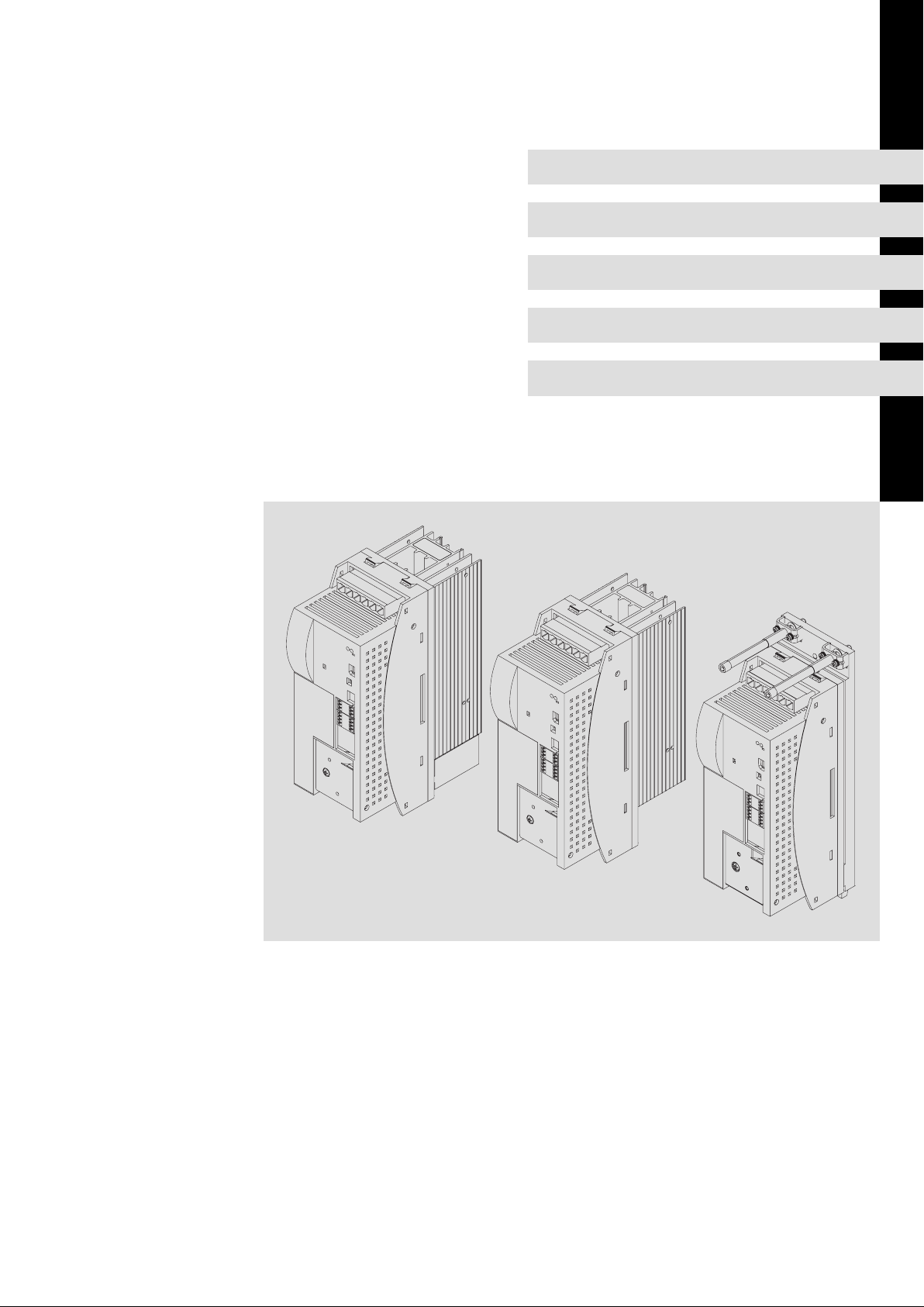
EDBCSXE040
.@y?
Ä.@y?ä
Operating Instructions
ECS
ECSEExxx / ECSDExxx / ECSCExxx
Power supply module
Page 2

Please read these instructions before you start working!
Follow the enclosed safety instructions.
These instructions are valid for the ECSxE power supply modules as of version:
ECS x E xxx x 4 x xxx XX xx xx
Type
Design
E = standard panel−mounted unit, IP20
D = push−through technique (thermally separated)
C = cold−plate technique
Rated current
012 = 12 A
020 = 20 A
040 = 38.5 A
Fieldbus interface
C = system bus CAN
Voltage class
4 = 400 V/480 V
L
Input
Output
Overload
Type
Id.-No.
xxxxxxxx
ECSEAxxxC4BXXXXXVA02
EKZ
A-SW
h.h
1D74
ATTENTION
L ´appareil est sous tension
pendant 180s après la coupure
de la tension réseau
WARNING
Device is live up to
180s after removing
mains voltage
For detailed
{
Hans-Lenze-Straße1
D-31855 Aerzen
Made in Germany
2/PE DC a-aaa/aaaV
bb.b/bb.bA
3/PE AC c-ccc/cccV
dd.d/dd.dA 0-fffHz
ee.eA
1
ttttttttttt
Ser.-No.
Prod.-No.
yyyyyyyy
zzzz
B-SW
Parameter
H.H
Ind.
Conl.
Eq.
information refer to
the Instruction Manual
}
Technical version
B = standard
I = for IT systems
Variant
Hardware version
VA or higher
Operating software version (B−SW)
1.2 or higher
Tip!
Documentation and software updates for further Lenze products can be found on the
Internet in the "Services & Downloads" area under
http://www.Lenze.com
0Fig. 0Tab. 0
2
EDBCSXE040 EN 6.0
Page 3
ECSEE_002A
EDBCSXE040 EN 6.0
3
Page 4
Scope of supply
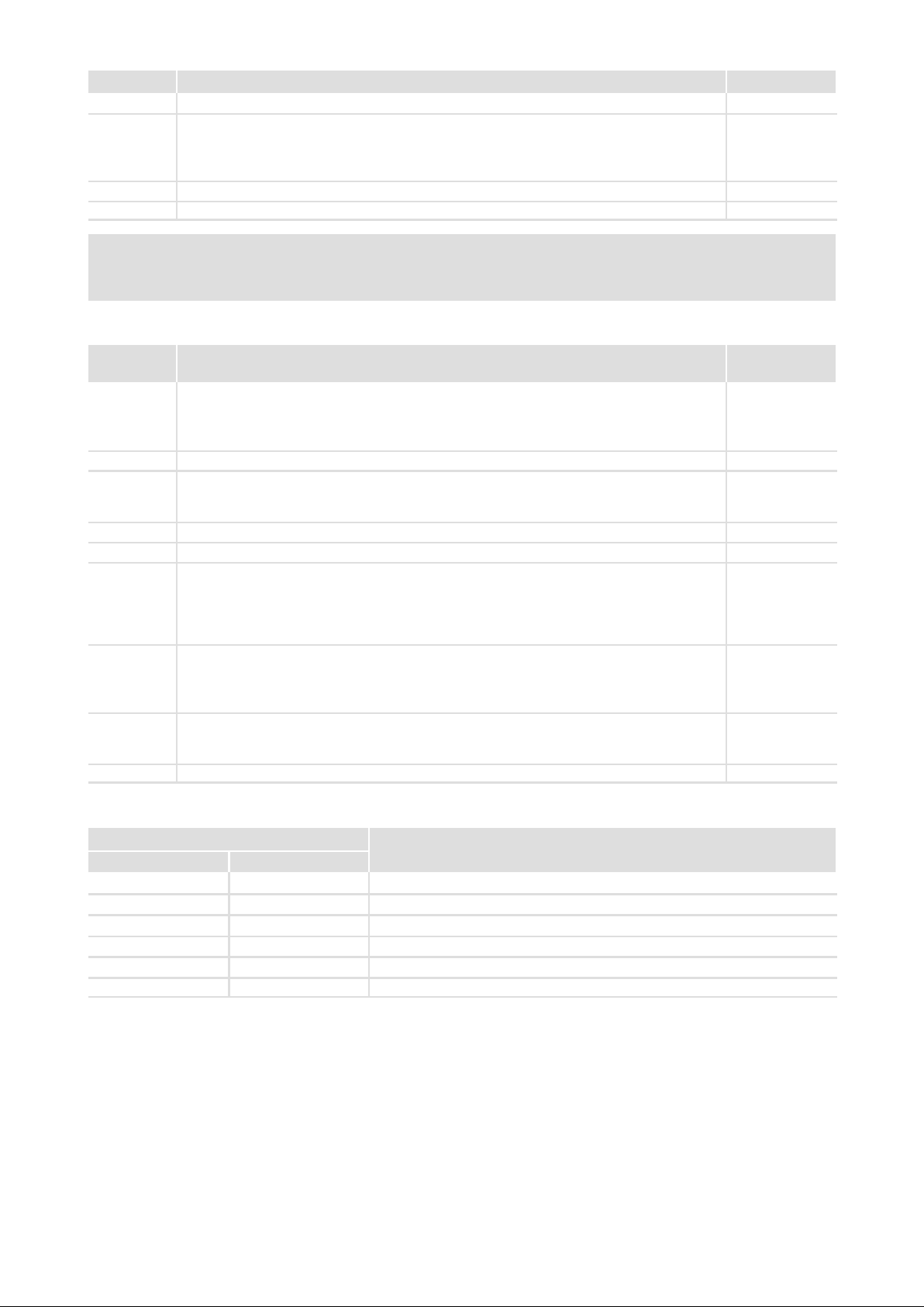
Position Description Quantity
ECSE... power supply module 1
Accessory kit with fixings according to the design ():
l "E" − panel−mounted device
l "D" − push−through technique
l "C" − cold−plate technique
Mounting Instructions 1
Drilling jig 1
Note!
The ECSZE000X0B connector set must be ordered separately.
Connections and interfaces
Position Description Detailed
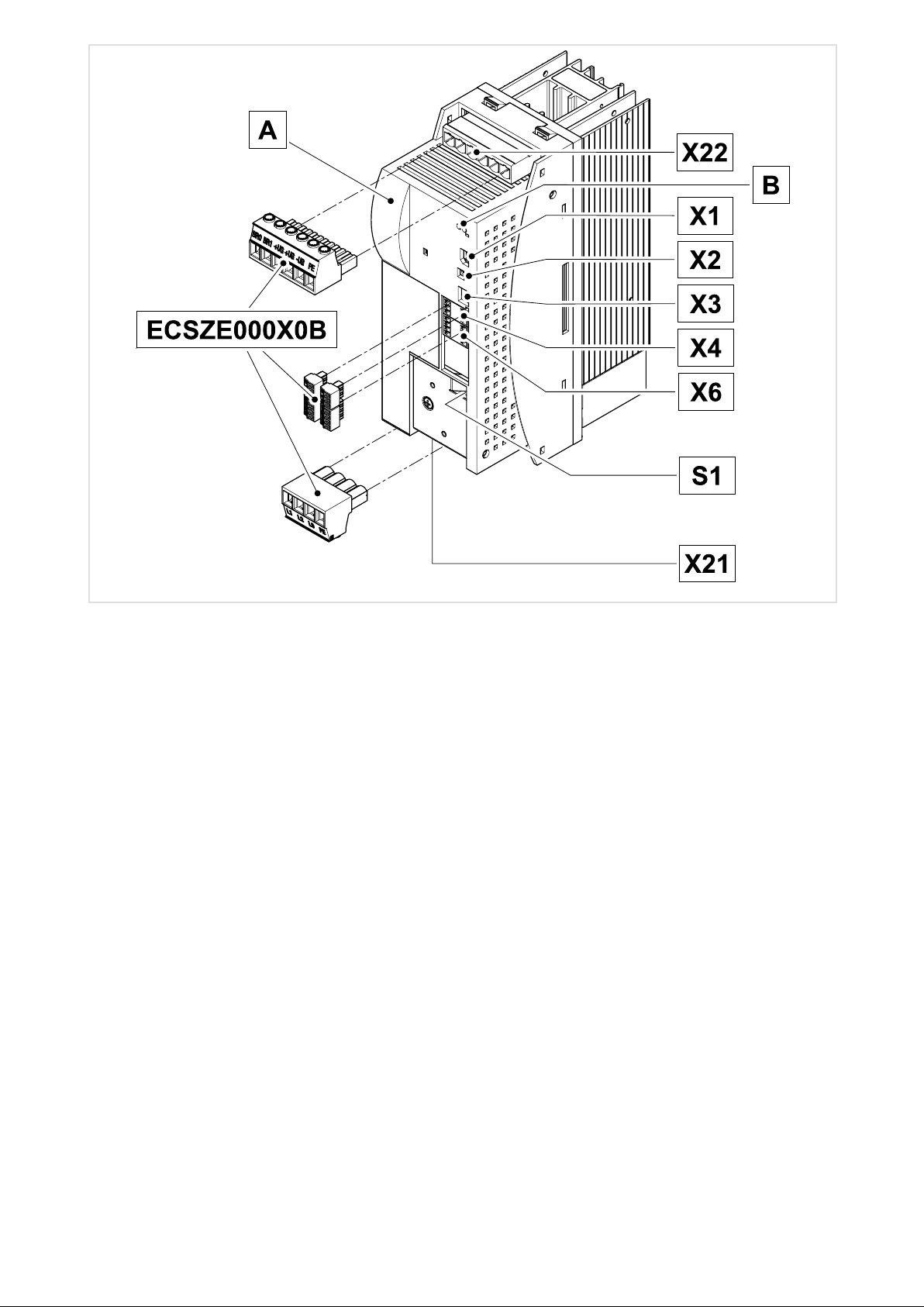
X22 Connections
l External brake resistor
l DC−bus voltage
l PE
LEDs: Status and fault display
X1 Automation interface (AIF) for
l Communication module
l Operating module (XT keypad)
X2 PE connection AIF
X3 Not assigned
X4 CAN connection
l System bus (CAN)
l Interface for
– master control and other modules
– PC/HMI for parameterisation and diagnostics
X6 Connections
S1 DIP switch
X21 Mains connection 40
l Low−voltage supply
l Digital inputs and outputs
l Thermostat contacts
l CAN node address (device address in the CAN network)
l CAN baud rate
42
52
72
53
51
95
1
information
Status displays
LED
Red Green
Off On Power supply module is enabled, no fault
Off Blinking Power supply module is inhibited (CINH), switch−on inhibit
Blinking, 1 Hz Off Fault / error (TRIP) / short−circuit braking error (KSB−TRIP) is active
Blinking, 3 Hz Off Message active
Blinking, 1 Hz Blinking Warning active with inhibited module
Blinking, 1 Hz On Warning active with enabled module
4
Description
EDBCSXE040 EN 6.0
Page 5

Contents i
1 Preface and general information 9 . . . . . . . . . . . . . . . . . . . . . . . . . . . . . . . . . . . . . . . . . . . .
1.1 About these Operating Instructions 9 . . . . . . . . . . . . . . . . . . . . . . . . . . . . . . . . . . . . .
1.2 Terminology used 9 . . . . . . . . . . . . . . . . . . . . . . . . . . . . . . . . . . . . . . . . . . . . . . . . . . . .
1.3 Scope of supply 10 . . . . . . . . . . . . . . . . . . . . . . . . . . . . . . . . . . . . . . . . . . . . . . . . . . . . . .
1.4 Properties of the ECSxE power supply module 11 . . . . . . . . . . . . . . . . . . . . . . . . . . . .
1.5 Legal regulations 12 . . . . . . . . . . . . . . . . . . . . . . . . . . . . . . . . . . . . . . . . . . . . . . . . . . . . .
2 Safety instructions 13 . . . . . . . . . . . . . . . . . . . . . . . . . . . . . . . . . . . . . . . . . . . . . . . . . . . . . . . .
2.1 General safety and application notes for Lenze power supply modules 13 . . . . . . . .
2.2 Residual hazards 16 . . . . . . . . . . . . . . . . . . . . . . . . . . . . . . . . . . . . . . . . . . . . . . . . . . . . .
2.3 Safety instructions for the installation according to UL or UR 17 . . . . . . . . . . . . . . . .
2.4 Notes used 18 . . . . . . . . . . . . . . . . . . . . . . . . . . . . . . . . . . . . . . . . . . . . . . . . . . . . . . . . . .
3 Technical data 19 . . . . . . . . . . . . . . . . . . . . . . . . . . . . . . . . . . . . . . . . . . . . . . . . . . . . . . . . . . . .
3.1 General data and operating conditions 19 . . . . . . . . . . . . . . . . . . . . . . . . . . . . . . . . .
3.2 Rated data 21 . . . . . . . . . . . . . . . . . . . . . . . . . . . . . . . . . . . . . . . . . . . . . . . . . . . . . . . . . .
3.3 External brake resistors 22 . . . . . . . . . . . . . . . . . . . . . . . . . . . . . . . . . . . . . . . . . . . . . . .
3.3.1 Assignment of external brake resistors 22 . . . . . . . . . . . . . . . . . . . . . . . . . . .
3.3.2 Rated data 22 . . . . . . . . . . . . . . . . . . . . . . . . . . . . . . . . . . . . . . . . . . . . . . . . . .
4 Mechanical installation 24 . . . . . . . . . . . . . . . . . . . . . . . . . . . . . . . . . . . . . . . . . . . . . . . . . . . .
4.1 Important notes 24 . . . . . . . . . . . . . . . . . . . . . . . . . . . . . . . . . . . . . . . . . . . . . . . . . . . . . .
4.2 Mounting with fixing rails (standard installation) 25 . . . . . . . . . . . . . . . . . . . . . . . . .
4.2.1 Dimensions 25 . . . . . . . . . . . . . . . . . . . . . . . . . . . . . . . . . . . . . . . . . . . . . . . . . .
4.2.2 Mounting steps 25 . . . . . . . . . . . . . . . . . . . . . . . . . . . . . . . . . . . . . . . . . . . . . .
4.3 Mounting with thermal separation (push−through technique) 26 . . . . . . . . . . . . . . .
4.3.1 Dimensions 27 . . . . . . . . . . . . . . . . . . . . . . . . . . . . . . . . . . . . . . . . . . . . . . . . . .
4.3.2 Mounting steps 29 . . . . . . . . . . . . . . . . . . . . . . . . . . . . . . . . . . . . . . . . . . . . . .
4.4 Mounting in cold−plate design 30 . . . . . . . . . . . . . . . . . . . . . . . . . . . . . . . . . . . . . . . . . .
4.4.1 Dimensions 31 . . . . . . . . . . . . . . . . . . . . . . . . . . . . . . . . . . . . . . . . . . . . . . . . . .
4.4.2 Mounting steps 32 . . . . . . . . . . . . . . . . . . . . . . . . . . . . . . . . . . . . . . . . . . . . . .
5 Electrical installation 33 . . . . . . . . . . . . . . . . . . . . . . . . . . . . . . . . . . . . . . . . . . . . . . . . . . . . . . .
5.1 Installation according to EMC (installation of a CE−typical drive system) 33 . . . . . . .
5.2 Drive system on the mains 36 . . . . . . . . . . . . . . . . . . . . . . . . . . . . . . . . . . . . . . . . . . . . .
5.2.1 Electrical isolation 36 . . . . . . . . . . . . . . . . . . . . . . . . . . . . . . . . . . . . . . . . . . . .
5.2.2 Supply forms / electrical supply conditions 37 . . . . . . . . . . . . . . . . . . . . . . .
5.2.3 Operation on public supply systems (compliance with EN 61000−3−2) 37 .
EDBCSXE040 EN 6.0
5
Page 6

Contentsi
5.3 Power terminals 38 . . . . . . . . . . . . . . . . . . . . . . . . . . . . . . . . . . . . . . . . . . . . . . . . . . . . .
5.3.1 Mains connection 40 . . . . . . . . . . . . . . . . . . . . . . . . . . . . . . . . . . . . . . . . . . . . .
5.3.2 Connection to the DC bus (+UG, −UG) 42 . . . . . . . . . . . . . . . . . . . . . . . . . . . .
5.3.3 Connection plan for mimimum wiring with internal brake resistor 43 . . .
5.3.4 Connection plan for mimimum wiring with external brake resistor 44 . . .
5.3.5 Connection of an ECSxK... capacitor module (optional) 47 . . . . . . . . . . . . . .
5.4 Control terminals 48 . . . . . . . . . . . . . . . . . . . . . . . . . . . . . . . . . . . . . . . . . . . . . . . . . . . .
5.4.1 Digital inputs and outputs 51 . . . . . . . . . . . . . . . . . . . . . . . . . . . . . . . . . . . . .
5.5 Automation interface (AIF) 52 . . . . . . . . . . . . . . . . . . . . . . . . . . . . . . . . . . . . . . . . . . . . .
5.6 Connection of system bus (CAN) 53 . . . . . . . . . . . . . . . . . . . . . . . . . . . . . . . . . . . . . . . .
6 Commissioning 55 . . . . . . . . . . . . . . . . . . . . . . . . . . . . . . . . . . . . . . . . . . . . . . . . . . . . . . . . . . .
6.1 Commissioning steps (overview) 56 . . . . . . . . . . . . . . . . . . . . . . . . . . . . . . . . . . . . . . . .
6.1.1 Basic settings with GDC 57 . . . . . . . . . . . . . . . . . . . . . . . . . . . . . . . . . . . . . . .
6.1.2 Operation via system bus (CAN) with higher−level master 59 . . . . . . . . . . .
6.1.3 Control via digital inputs 60 . . . . . . . . . . . . . . . . . . . . . . . . . . . . . . . . . . . . . . .
6.1.4 Operation via EtherCAT with higher−level master 61 . . . . . . . . . . . . . . . . . .
6.2 Setting the mains voltage 62 . . . . . . . . . . . . . . . . . . . . . . . . . . . . . . . . . . . . . . . . . . . . .
6.3 Setting chopper operation and short−circuit braking 63 . . . . . . . . . . . . . . . . . . . . . . .
6.4 Configuring power supply enable input 64 . . . . . . . . . . . . . . . . . . . . . . . . . . . . . . . . . .
6.5 Operation with external brake resistor 66 . . . . . . . . . . . . . . . . . . . . . . . . . . . . . . . . . . .
6.6 After mains switch−on 67 . . . . . . . . . . . . . . . . . . . . . . . . . . . . . . . . . . . . . . . . . . . . . . . .
6.6.1 Detection of the mains parameters 67 . . . . . . . . . . . . . . . . . . . . . . . . . . . . . .
6.6.2 Monitoring functions 67 . . . . . . . . . . . . . . . . . . . . . . . . . . . . . . . . . . . . . . . . .
6.6.3 Fault responses 68 . . . . . . . . . . . . . . . . . . . . . . . . . . . . . . . . . . . . . . . . . . . . . .
7 Parameter setting 69 . . . . . . . . . . . . . . . . . . . . . . . . . . . . . . . . . . . . . . . . . . . . . . . . . . . . . . . . .
7.1 General information 69 . . . . . . . . . . . . . . . . . . . . . . . . . . . . . . . . . . . . . . . . . . . . . . . . .
7.2 Parameter setting with "Global Drive Control" (GDC) 70 . . . . . . . . . . . . . . . . . . . . . .
7.3 Parameter setting with the XT EMZ9371BC keypad 72 . . . . . . . . . . . . . . . . . . . . . . . .
7.3.1 Connecting the keypad 72 . . . . . . . . . . . . . . . . . . . . . . . . . . . . . . . . . . . . . . . .
7.3.2 Description of the display elements 73 . . . . . . . . . . . . . . . . . . . . . . . . . . . . .
7.3.3 Description of the function keys 74 . . . . . . . . . . . . . . . . . . . . . . . . . . . . . . . .
7.3.4 Changing and saving parameters 75 . . . . . . . . . . . . . . . . . . . . . . . . . . . . . . .
8 Configuration 76 . . . . . . . . . . . . . . . . . . . . . . . . . . . . . . . . . . . . . . . . . . . . . . . . . . . . . . . . . . . . .
8.1 General information about the system bus (CAN) 77 . . . . . . . . . . . . . . . . . . . . . . . . .
8.1.1 Structure of the CAN data telegram 77 . . . . . . . . . . . . . . . . . . . . . . . . . . . . .
8.1.2 Communication phases of the CAN network (NMT) 79 . . . . . . . . . . . . . . . .
8.1.3 Process data transfer 82 . . . . . . . . . . . . . . . . . . . . . . . . . . . . . . . . . . . . . . . . . .
8.1.4 Parameter data transfer 88 . . . . . . . . . . . . . . . . . . . . . . . . . . . . . . . . . . . . . . .
8.1.5 Addressing of the parameter and process data objects 94 . . . . . . . . . . . . .
6
EDBCSXE040 EN 6.0
Page 7

Contents i
8.2 Configuring system bus (CAN) 95 . . . . . . . . . . . . . . . . . . . . . . . . . . . . . . . . . . . . . . . . . .
8.2.1 Setting CAN node address and baud rate 95 . . . . . . . . . . . . . . . . . . . . . . . . .
8.2.2 Individual addressing 98 . . . . . . . . . . . . . . . . . . . . . . . . . . . . . . . . . . . . . . . . .
8.2.3 Display of the resulting identifiers 99 . . . . . . . . . . . . . . . . . . . . . . . . . . . . . . .
8.2.4 Defining boot−up master in the drive system 100 . . . . . . . . . . . . . . . . . . . . . .
8.2.5 Setting the mode for process data transfer 101 . . . . . . . . . . . . . . . . . . . . . . .
8.2.6 Setting of boot−up time/cycle time 101 . . . . . . . . . . . . . . . . . . . . . . . . . . . . . .
8.2.7 Node guarding 102 . . . . . . . . . . . . . . . . . . . . . . . . . . . . . . . . . . . . . . . . . . . . . . .
8.2.8 Executing a reset node 104 . . . . . . . . . . . . . . . . . . . . . . . . . . . . . . . . . . . . . . . .
8.2.9 Assignment of the control word 105 . . . . . . . . . . . . . . . . . . . . . . . . . . . . . . . .
8.2.10 Assignment of status words 106 . . . . . . . . . . . . . . . . . . . . . . . . . . . . . . . . . . . .
8.2.11 Bus status 107 . . . . . . . . . . . . . . . . . . . . . . . . . . . . . . . . . . . . . . . . . . . . . . . . . . .
8.2.12 Diagnostics PDO (C0390/1 ... 8) 108 . . . . . . . . . . . . . . . . . . . . . . . . . . . . . . . . .
8.3 Overview of monitoring functions 109 . . . . . . . . . . . . . . . . . . . . . . . . . . . . . . . . . . . . . .
8.4 Configuring monitoring functions 111 . . . . . . . . . . . . . . . . . . . . . . . . . . . . . . . . . . . . . .
8.4.1 Fault responses 111 . . . . . . . . . . . . . . . . . . . . . . . . . . . . . . . . . . . . . . . . . . . . . .
8.4.2 Mains monitoring (LP0, LP1) 113 . . . . . . . . . . . . . . . . . . . . . . . . . . . . . . . . . . . .
8.4.3 Voltage supply monitoring − control electronics (U15) 115 . . . . . . . . . . . . . .
8.4.4 DC bus monitoring (OU, OC1, OC2, OC3) 115 . . . . . . . . . . . . . . . . . . . . . . . . .
8.4.5 Temperature monitoring of device heatsink (OH) / inside the device (OH1) . . . .
115
8.4.6 Fan monitoring (FAN1) 115 . . . . . . . . . . . . . . . . . . . . . . . . . . . . . . . . . . . . . . . .
8.4.7 Brake resistor monitoring (OC6, OH3) 116 . . . . . . . . . . . . . . . . . . . . . . . . . . . .
8.4.8 Brake chopper IGBT monitoring (OC4) 117 . . . . . . . . . . . . . . . . . . . . . . . . . . .
8.4.9 Device utilisation / I x t monitoring (OC5) 117 . . . . . . . . . . . . . . . . . . . . . . . .
8.4.10 Communication monitoring (CE1 ... CE4, node guarding) 118 . . . . . . . . . . . .
9 Diagnostics 120 . . . . . . . . . . . . . . . . . . . . . . . . . . . . . . . . . . . . . . . . . . . . . . . . . . . . . . . . . . . . . . .
9.1 Diagnostics with Global Drive Control (GDC) 120 . . . . . . . . . . . . . . . . . . . . . . . . . . . . . .
9.2 Diagnostics with the XT EMZ9371BC keypad 123 . . . . . . . . . . . . . . . . . . . . . . . . . . . . .
9.3 Diagnostics with PCAN−View 124 . . . . . . . . . . . . . . . . . . . . . . . . . . . . . . . . . . . . . . . . . . .
9.3.1 Monitoring of telegram traffic on the CANopen bus 124 . . . . . . . . . . . . . . .
9.3.2 Setting all nodes to the "Operational" status 126 . . . . . . . . . . . . . . . . . . . . . .
9.4 Advanced diagnostics via diagnostics PDO (CAN2_OUT) 127 . . . . . . . . . . . . . . . . . . . .
10 Troubleshooting and fault elimination 129 . . . . . . . . . . . . . . . . . . . . . . . . . . . . . . . . . . . . . . .
10.1 Fault analysis 129 . . . . . . . . . . . . . . . . . . . . . . . . . . . . . . . . . . . . . . . . . . . . . . . . . . . . . . . .
10.1.1 Fault analysis via the LED display 129 . . . . . . . . . . . . . . . . . . . . . . . . . . . . . . . .
10.1.2 Fault analysis with keypad XT EMZ9371BC 129 . . . . . . . . . . . . . . . . . . . . . . .
10.1.3 Fault analysis with the history buffer 130 . . . . . . . . . . . . . . . . . . . . . . . . . . . .
10.2 Fault messages 131 . . . . . . . . . . . . . . . . . . . . . . . . . . . . . . . . . . . . . . . . . . . . . . . . . . . . . .
10.2.1 Causes and remedies 131 . . . . . . . . . . . . . . . . . . . . . . . . . . . . . . . . . . . . . . . . . .
10.2.2 Reset fault messages (TRIP−RESET) 133 . . . . . . . . . . . . . . . . . . . . . . . . . . . . . . .
EDBCSXE040 EN 6.0
7
Page 8

Contentsi
11 Appendix 134 . . . . . . . . . . . . . . . . . . . . . . . . . . . . . . . . . . . . . . . . . . . . . . . . . . . . . . . . . . . . . . . .
11.1 Code list 134 . . . . . . . . . . . . . . . . . . . . . . . . . . . . . . . . . . . . . . . . . . . . . . . . . . . . . . . . . . . .
11.2 Table of attributes 152 . . . . . . . . . . . . . . . . . . . . . . . . . . . . . . . . . . . . . . . . . . . . . . . . . . . .
11.3 Overview of accessories 155 . . . . . . . . . . . . . . . . . . . . . . . . . . . . . . . . . . . . . . . . . . . . . . .
11.3.1 Connector sets 155 . . . . . . . . . . . . . . . . . . . . . . . . . . . . . . . . . . . . . . . . . . . . . . .
11.3.2 Shield mounting kit 155 . . . . . . . . . . . . . . . . . . . . . . . . . . . . . . . . . . . . . . . . . . .
11.3.3 Axis modules 155 . . . . . . . . . . . . . . . . . . . . . . . . . . . . . . . . . . . . . . . . . . . . . . . .
11.3.4 Capacitor modules 156 . . . . . . . . . . . . . . . . . . . . . . . . . . . . . . . . . . . . . . . . . . . .
11.3.5 Components for operation and communication 156 . . . . . . . . . . . . . . . . . . .
11.3.6 Brake resistor 157 . . . . . . . . . . . . . . . . . . . . . . . . . . . . . . . . . . . . . . . . . . . . . . . .
11.3.7 Mains fuses 158 . . . . . . . . . . . . . . . . . . . . . . . . . . . . . . . . . . . . . . . . . . . . . . . . . .
11.3.8 Mains chokes 158 . . . . . . . . . . . . . . . . . . . . . . . . . . . . . . . . . . . . . . . . . . . . . . . .
11.3.9 RFI filters 159 . . . . . . . . . . . . . . . . . . . . . . . . . . . . . . . . . . . . . . . . . . . . . . . . . . . .
11.3.10 Motors 159 . . . . . . . . . . . . . . . . . . . . . . . . . . . . . . . . . . . . . . . . . . . . . . . . . . . . . .
12 Index 160 . . . . . . . . . . . . . . . . . . . . . . . . . . . . . . . . . . . . . . . . . . . . . . . . . . . . . . . . . . . . . . . . . . . .
8
EDBCSXE040 EN 6.0
Page 9
Preface and general information
About these Operating Instructions
1 Preface and general information
1.1 About these Operating Instructions
These Operating Instructions help you with the connection and commissioning of the
ECSxE series power supply modules.
They contain safety instructions which must be observed!
All persons working on and with ECSxE series power supply modules must have the
Operating Instructions available and must observe the information and notes relevant for
their work.
The Operating Instructions must always be in a complete and perfectly readable state.
1.2 Terminology used
1
Term In the following text used for
Power supply
module
ECSxE... Any power supply module of the ECS series
Capacitor module ECSxK series capacitor module
ECSxK... Any capacitor module of the ECS series
Axis module
Controller
ECSxS...
ECSxP...
ECSxM...
ECSxA ...
Drive system Drive systems with:
24 V supply
Low−voltage supply
KSB Short−circuit braking: Quick discharge of the DC bus via the brake resistor
AIF Automation InterFace
Cxxxx/y Subcode y of code Cxxxx (e. g. C0470/3 = subcode 3 of code C0470)
Xk/y Terminal y on plug connector Xk (e. g. X6/B+ = terminal B+ on plug connector X6)
ECSxE... power supply module
Any axis module of the ECS series:
l ECSxS... − "Speed and Torque" mode
l ECSxP... − "Posi and Shaft" mode
l ECSxM... − "Motion" mode
l ECSxA... − "Application" mode
l Axis modules ECSxS... / ECSxP... / ECSxM... / ECSxA...
l ECSxE... power supply modules
l ECSxK... capacitor modules
l Other Lenze drive components
Voltage supply of the control card, voltage range 20 ... 30 V DC (±0 V)
EDBCSXE040 EN 6.0
9
Page 10

1
Preface and general information
Scope of supply
1.3 Scope of supply
The scope of supply of the ECSxE... power supply module includes:
ƒ Standard device
ƒ Accessory kit with fixings according to the design:
– "E" − panel−mounted device
– "D" − push−through technique
– "C" − cold−plate technique
ƒ Mounting Instructions
ƒ Drilling jig
Accessories
The appendix includes information on the following accessories: ( 155).
ƒ Connector sets for
– Power supply modules: ECSZE000X0B
– Capacitor modules: ECSZK000X0B
– Axis modules: ECSZA000X0B
ƒ Shield mounting ECSZS000X0B001 (EMC accessories)
ƒ Communication modules for the automation interface (AIF)
ƒ ECSxS/P/M/A... axis module
ƒ ECSxK series capacitor module
ƒ Brake resistors
ƒ Mains fuses
ƒ Mains chokes
ƒ RFI filters
ƒ Motors
10
EDBCSXE040 EN 6.0
Page 11

Preface and general information
Properties of the ECSxE power supply module
1.4 Properties of the ECSxE power supply module
ƒ Generation of the DC−bus voltage for an ECS drive system or single drive
ƒ Controlled charging of the DC bus
ƒ Check of the DC bus for earth fault and short circuit during mains connection
ƒ Automatic detection of mains voltage
ƒ Mains failure monitoring
ƒ Single−phase mains current measurement for diagnostics
ƒ Internal brake chopper IGBT
ƒ Mains−voltage dependent adaptation of brake chopper switch−on voltage
ƒ Internal brake resistor with monitoring (not for ECSCE series in cold plate design)
ƒ Connection of external brake resistor with temperature switch possible
ƒ Communication via integrated system bus interface (CAN) for parameterisation and
transmission of process data
1
ƒ Connection to an EtherCAT fieldbus via the automation interface (AIF)
EDBCSXE040 EN 6.0
11
Page 12

1
Preface and general information
Legal regulations
1.5 Legal regulations
Identification
Application as
directed
Liability l The information, data and notes in these Instructions met the state of the art at the time of printing. Claims
Warranty l Terms of warranty: See terms of sales and delivery of Lenze Drive Systems GmbH.
Nameplate CE designation Manufacturer
Lenze power supply modules are
unambiguously designated by the
contents of the nameplate.
ECSxE series power supply modules
l must only be operated under the conditions prescribed in these Instructions.
l are components
– for the supply of servo inverters with DC bus voltage.
– for installation in a machine.
– for assembly with other components to form a machine.
l are electrical equipment for the installation in control cabinets or similar closed operating areas.
l comply with the protective requirements of the EC Low−Voltage Directive.
l are not machines for the purpose of the EC Machinery Directive.
l are not to be used as domestic appliances, but for industrial purposes only.
Drive systems with ECSxE series power supply modules
l comply with the EC Directive "Electromagnetic compatibility" if they are installed according to the guidelines
of CE−typical drive systems.
l can be used
– at non−public mains.
– in industrial premises.
l The user is responsible for the compliance of his application with the EC Directives.
Any other use shall be deemed inappropriate!
on modifications referring to power supply modules and components which have already been supplied
cannot be derived from the information, illustrations and descriptions given in these Instructions.
l The specifications, processes, and circuitry described in these Instructions are for guidance only and must be
adapted to your own specific application. Lenze does not take responsibility for the suitability of the process
and circuit proposals.
l Lenze does not accept any liability for damage and operating interference caused by:
– Disregarding the Operating Instructions
– Unauthorised modifications to the power supply module
– Operating errors
– Improper working on and with the power supply module
l Warranty claims must be made to Lenze immediately after detecting the deficiency or fault.
l The warranty is void in all cases where liability claims cannot be made.
Conforms to the EC Low−Voltage
Directive
Lenze Automation GmbH
Grünstraße 36
D−40667 Meerbusch
12
EDBCSXE040 EN 6.0
Page 13

Safety instructions
General safety and application notes
2 Safety instructions
2.1 General safety and application notes for Lenze power supply modules
(acc. to Low−Voltage Directive 2006/95/EC)
For your personal safety
Depending on their degree of protection, Lenze power supply modules and their accessory
components can be live, moving and rotating during operation. Surfaces can be hot.
Non−authorised removal of the required cover, inappropriate use, incorrect installation or
operation, creates the risk of severe injury to persons or damage to material assets.
For more information please see the documentation.
High amounts of energy are produced in the power supply module. Therefore it is required
to wear personal protective equipment (body protection, headgear, eye protection, ear
protection, hand guard) when working with the power supply module.
2
All operations concerning transport, installation, and commissioning as well as
maintenance must be carried out by qualified, skilled personnel (IEC 364 and
CENELEC HD 384 or DIN VDE 0100 and IEC report 664 or DIN VDE 0110 and national
regulations for the prevention of accidents must be observed).
According to this basic safety information, qualified, skilled personnel are persons who are
familiar with the assembly, installation, commissioning, and operation of the product and
who have the qualifications necessary for their occupation.
Application as directed
Power supply modules are components which are designed for installation in electrical
systems or machinery. They are not to be used as domestic appliances, but only for
industrial purposes according to EN 61000−3−2.
When installing the power supply modules in machines, commissioning (i.e. starting of
operation as directed) is prohibited until it is proven that the machine complies with the
regulations of the EC Directive 98/37/EC (Machinery Directive); EN 60204 must be
observed.
Commissioning (i.e. starting of operation as directed) is only allowed when there is
compliance with the EMC Directive (89/336/EEC).
The power supply modules meet the requirements of the Low−Voltage Directive
73/23/EEC. The harmonised standard EN 61800−5−1 applies to the power supply modules.
EDBCSXE040 EN 6.0
The technical data as well as the supply conditions can be obtained from the nameplate
and the documentation. They must be strictly observed.
Warning: The power supply modules are products which can be installed in drive systems
of category C2 according to EN 61800−3. These products can cause radio interference in
residential areas. In this case, special measures can be necessary.
Transport, storage
Please observe the notes on transport, storage, and appropriate handling.
Observe the climatic conditions according to the technical data.
13
Page 14

2
Safety instructions
General safety and application notes
Installation
The power supply modules must be installed and cooled according to the instructions
given in the corresponding documentation.
Ensure proper handling and avoid excessive mechanical stress. Do not bend any
components and do not change any insulation distances during transport or handling. Do
not touch any electronic components and contacts.
Power supply modules contain electrostatically sensitive components which can easily be
damaged by inappropriate handling. Do not damage or destroy any electrical components
since this might endanger your health!
Electrical connection
When working on live power supply modules, applicable national regulations (e.g. VBG 4)
must be observed.
The electrical installation must be carried out according to the appropriate regulations
(e.g. cable cross−sections, fuses, PE connection). Additional information can be obtained
from the documentation.
The documentation contains information about installation in compliance with EMC
(shielding, earthing, filters, and cables). These notes must also be observed for CE−marked
power supply modules. The manufacturer of the system or machine is responsible for
compliance with the required limit values demanded by EMC legislation. The controllers
must be installed in housings (e.g. control cabinets) to meet the limit values for radio
interferences valid at the site of installation. The housings must enable an EMC−compliant
installation. Observe in particular that e.g. the control cabinet doors should have a
circumferential metal connection to the housing. Reduce housing openings and cutouts to
a minimum.
Operation
If necessary, systems including power supply modules must be equipped with additional
monitoring and protection devices according the valid safety regulations (e.g. law on
technical equipment, regulations for the prevention of accidents). The power supply
modules can be adapted to your application. Please observe the corresponding
information given in the documentation.
After the power supply module has been disconnected from the supply voltage, all live
components and power terminals must not be touched immediately because capacitors
can still be charged. Please observe the corresponding stickers on the power supply
module.
All protection covers and doors must be shut during operation.
14
Note for UL approved systems with integrated power supply modules: UL warnings are
notes which only apply to UL systems. The documentation contains special UL notes.
EDBCSXE040 EN 6.0
Page 15

Safety instructions
General safety and application notes
Maintenance and servicing
The power supply modules do not require any maintenance if the prescribed operating
conditions are observed.
If the ambient air is polluted, the cooling surfaces of the power supply module may become
dirty or the ventilation slots may be obstructed. Therefore, clean the cooling surfaces and
ventilation slots periodically under these operating conditions. Do not use sharp or pointed
tools for this purpose!
Disposal
Recycle metal and plastic materials. Ensure professional disposal of assembled PCBs.
The product−specific safety and application notes given in these instructions must be
observed!
2
EDBCSXE040 EN 6.0
15
Page 16

2
2.2 Residual hazards
Safety instructions
Residual hazards
Protection of persons
ƒ Before working on the power supply module, check that no voltage is applied to the
power terminals,
– the power terminals +UG, −UG, BR0 and BR1 remain live for at least 3 minutes after
mains disconnection.
– because the power terminals +UG, −UG, BR0 and BR1 remain live when the motor
is stopped.
ƒ The operating temperature of the heatsink can exceed 70 °C:
– Direct skin contact with the heatsink results in burns!
ƒ The leakage current to PE is > 3.5 mA AC or > 10 mA DC. Therefore, two PE
connections are installed for protective reasons.
– Comply with the requirements of EN 61800−5−1 for high leakage currents!
ƒ For operation of the power supply module with an earth−leakage circuit breaker:
– The power supply modules are provided with an internal mains rectifier. In the
event of a short−circuit to frame, a non−pulsating DC fault current can prevent the
tripping of AC−sensitive or pulse−current−sensitive earth−leakage circuit breakers
and thus block the protective function for all electrical equipment operated on
these earth−leakage circuit breakers.
– If a residual current device (RCD) is used as a protective means in the case of direct
or indirect contact, only a residual current device (RCD) of type B may be used.
Otherwise, another protective measure, such as separation from the environment
through double or reinforced insulation or disconnection from the mains by means
of a transformer must be used.
Device protection
ƒ The power supply module may only be driven from balanced mains supplies. Mains
supplies with earthed phase are not permitted.
ƒ Observe the max. permissible mains voltage. Higher voltages will damage the power
supply module.
ƒ The power supply module contains electrostatic sensitive devices. The personnel
must be free of electrostatic charge prior to assembly and service operations.
ƒ All pluggable connection terminals must only be connected or disconnected when
no voltage is applied!
ƒ The power terminals +UG, −UG and PE are not protected against polarity reversal.
– When wiring, observe the polarity of the power terminals!
ƒ Operation is not permitted
– without the use of a brake resistor.
– if an internal brake resistor and an external brake resistor are used simultaneously.
– if several power supply modules are connected in parallel.
16
EDBCSXE040 EN 6.0
Page 17

Safety instructions
Safety instructions for the installation according to U
or U
L
2
R
2.3 Safety instructions for the installation according to UL or U
Warnings!
General markings:
ƒ Use 60/75 °C or 75 °C copper wire only.
ƒ Maximum ambient temperature 55 °C, with reduced output current.
Markings provided for the supply units:
ƒ Suitable for use on a circuit capable of delivering not more than 5000 rms
symmetrical amperes, 480 V max, when protected by K5 or H Fuses
(400/480 V devices).
ƒ Alternate − Circuit breakers (either inverse−time, instantaneous trip types or
combination motor controller type E) may be used in lieu of above fuses
when it is shown that the let−through energy (i
current (I
than that of the non−semiconductor type K5 fuses with which the drive has
been tested.
ƒ Alternate − An inverse−time circuit breaker may be used, sized upon the
input rating of the drive, multiplied by 300 %.
Markings provided for the inverter units:
ƒ The inverter units shall be used with supply units which are provided with
overvoltage devices or systems in accordance with UL840 2nd ed., Table 5.1.
ƒ The devices are provided with integral overload and integral thermal
protection for the motor.
ƒ The devices are not provided with overspeed protection.
) of the inverse−time current−limiting circuit breaker will be less
p
R
2
t) and peak let−through
Terminal tightening torque of lb−in (Nm)
Terminal lb−in Nm
X 21, X 22, X 23, X 24 10.6 ... 13.3 1.2 ... 1.5
X4, X6, X14 1.95 ... 2.2 0.22 ... 0.25
X 25 4.4 ... 7.1 0.5 ... 0.8
Wiring diagram AWG
Terminal AWG
X 21, X 22, X 23, X 24 12 ... 8
X4, X6, X14 28 ... 16
X 25 24 ... 12
EDBCSXE040 EN 6.0
17
Page 18

2
2.4 Notes used
Safety instructions
Notes used
The following pictographs and signal words are used in this documentation to indicate
dangers and important information:
Safety instructions
Structure of safety instructions:
Danger!
Pictograph and signal word Meaning
Danger!
Danger!
Stop!
Application notes
(characterises the type and severity of danger)
Note
(describes the danger and gives information about how to prevent dangerous
situations)
Danger of personal injury through dangerous electrical voltage.
Reference to an imminent danger that may result in death or
serious personal injury if the corresponding measures are not
taken.
Danger of personal injury through a general source of danger.
Reference to an imminent danger that may result in death or
serious personal injury if the corresponding measures are not
taken.
Danger of property damage.
Reference to a possible danger that may result in property
damage if the corresponding measures are not taken.
Pictograph and signal word Meaning
Note!
Tip!
Special safety instructions and application notes for UL and UR
Pictograph and signal word Meaning
Warnings!
Warnings!
Important note to ensure troublefree operation
Useful tip for simple handling
Reference to another documentation
Safety or application note for the operation of a UL−approved
device in UL−approved systems.
Possibly the drive system is not operated in compliance with UL
if the corresponding measures are not taken.
Safety or application note for the operation of a UR−approved
device in UL−approved systems.
Possibly the drive system is not operated in compliance with UL
if the corresponding measures are not taken.
18
EDBCSXE040 EN 6.0
Page 19
Technical data
General data and operating conditions
3 Technical data
3.1 General data and operating conditions
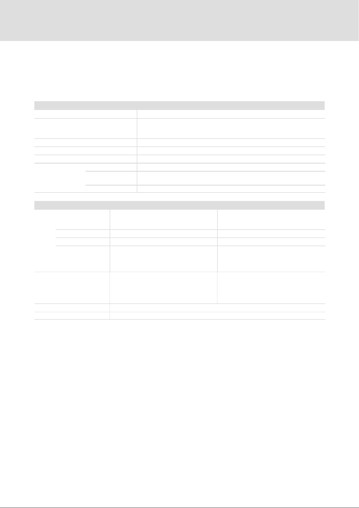
Standards and operating conditions
Conformity CE Low−Voltage Directive (2006/95/EC)
Approvals UL 508C Power Conversion Equipment
Underwriter Laboratories (File No. E132659)
for USA and Canada
Packaging (DIN 4180) Shipping package
Installation Installation in control cabinet
Mounting position Vertically suspended
Free space
above ³ 65 mm
below ³ 65 mm
With ECSZS000X0B shield mounting kit: > 195 mm
to the sides Can be mounted directly side by side without any clearance
3
Environmental conditions
Climate 3k3 in accordance with IEC/EN 60721−3−3
Condensation, splash water and ice formation
not permissible.
Storage IEC/EN 60721−3−1 1K3 (−25 ... + 55 °C)
Transport IEC/EN 60721−3−2 2K3 (−25 ... +70 °C)
Operation IEC/EN 60721−3−3 3K3 (0 ... + 55 °C)
l Atmospheric pressure: 86 ... 106 kPa
l Above +40 °C: reduce the rated output
current by 2 %/°C.
Site altitude 0 ... 4000 m amsl
l Reduce rated output current by
5 %/1000 m above 1000 m amsl.
l Over 2000 m amsl: use is only permitted in
environments with overvoltage category II
Pollution VDE 0110 part 2 pollution degree 2
Vibration resistance Accelerational stability up to 0.7 g (Germanischer Lloyd, general conditions)
EDBCSXE040 EN 6.0
19
Page 20

3
Technical data
General data and operating conditions
General electrical data
EMC Compliance with the requirements acc. to EN 61800−3
Noise emission Compliance with the limit class A acc. to EN 55011
(achieved by using collective filters typical for the application)
Noise immunity
Insulation resistance Overvoltage category III acc. to VDE 0110
Discharge current to PE (acc. to
EN 61800−5−1)
Enclosure IP20 (NEMA 250 type 1) for
Protective measures against l Short circuit in power terminals (short−circuit−proof at mains connection)
Protective insulation of control circuits Protective separation from the mains
1)
The noise immunity with the severities given must be ensured by the control cabinet. The user must check the
compliance of the severities given.
Requirements acc. to EN 61800−3
Requirement Standard Severity
1)
ESD
Conducted high frequency EN 61000−4−6 10 V; 0.15 ... 80 MHz
RF interference (housing) EN 61000−4−3 3, i. e. 10 V/m;
Burst EN 61000−4−4 3/4, i. e. 2 kV/5 kHz
Surge (surge voltage on
mains cable)
> 3.5 mA AC during operation
l standard mounting (panel−mounted unit)
l mounting in cold−plate technique
l mounting with thermal separation (push−through technique), IP54 on heatsink
side
l Short circuit in auxiliary circuits
– Digital outputs: short−circuit−proof
– System bus and encoder systems: partially short−circuit−proof (corresponding
monitoring functions can be deactivated, if required.)
l Earth fault (earth−fault protected at mains connection)
l Overvoltage
Double/reinforced insulation acc. to EN 61800−5−1
EN 61000−4−2 3, i. e.
l 8 kV for air discharge
l 6 kV for contact discharge
80 ... 1000 MHz
EN 61000−4−5 3, i. e. 1.2/50 ms
l 1 kV phase/phase
l 2 kV phase/PE
20
EDBCSXE040 EN 6.0
Page 21

Technical data
Rated data
3
3.2 Rated data
Rated data Type ECSxE012 ECSxE020 ECSxE040
Mains voltage V
Rated mains voltage V
Mains frequency f
Rated mains current I
Max. mains current
Rated direct current (effective value) I
Max. connectable DC bus capacitance C [uF] 6600
Low−voltage supply of control electronics
Power loss, total
Inside the device
Heatsink
Velocity of cooling air
(only for ECSDE...)
Mass m [kg] approx. 2.5 approx. 3.2
Internal brake resistor
(not available for ECSCE...)
Continuous power
Max. braking power
Max. braking energy
Max. on−time
Required recovery time
1)
For the dimensioning of a 24 V supply it may be necessary to add the current demand of the digital output (0.7 A).
[V] 3 x 200 −10 % ... 3 x 480 +10 %
mains
[V] 3 x 400 V
mains rated
mains
mains rated
I
mains max
DC rated,RMS
[Hz] 45 ... 66
[A] 9.6 15.9 31.3
5 x I
mains rated
[A]
[A] 12.0 20.0 38.5
2 x I
1.5 x I
mains rated
for 50 ms / 0 x I
mains rated
for 1 s / 0 x I
for 10 s / 0 x I
mains rated
mains rated
mains rated
U [V] 20 ... 30
I
[A] 0.35
typ.
I
[A] 0.5 A at 24 V
max
1)
50 68 111
PV [W]
20 23 30
30 45 81
VC [m/s] 3
RB [Ω] 39 20
Pd [kW] 0.12 0.15
P
[kW] 13.8 27.0
Bmax
WB [kWs] 2.5 3.0
te [s] 0.15 0.10
ta [s] 20
for 1.2 s
for 3 s
for 12.75 s
EDBCSXE040 EN 6.0
21
Page 22
3
Technical data
External brake resistors
Assignment of external brake resistors
3.3 External brake resistors
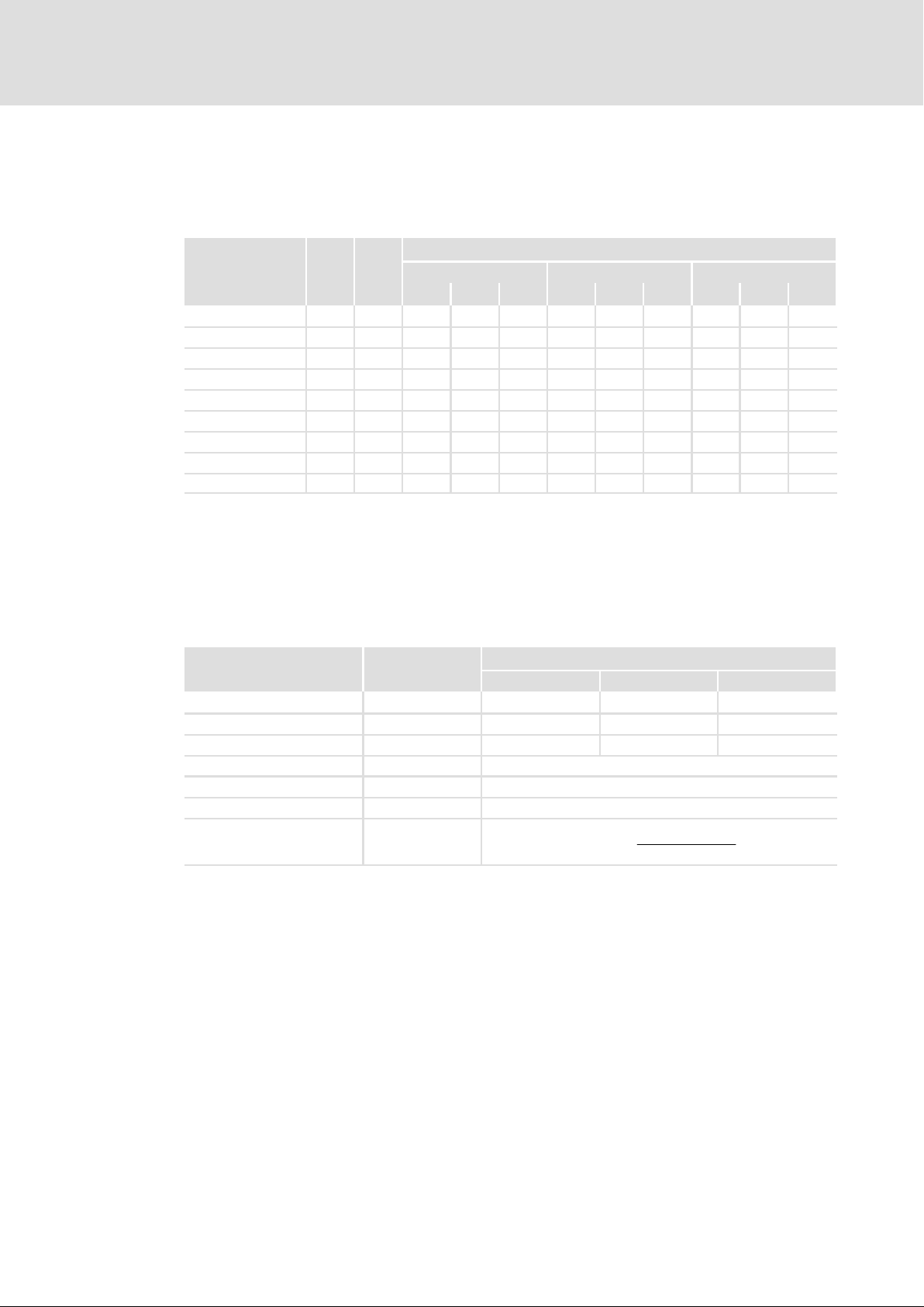
3.3.1 Assignment of external brake resistors
P
Brake resistor W
ERBM082R100W 82 0.10 l
ERBM039R120W 39 0.12 l
ERBM020R150W 20 0.15 l
ERBD082R600W 82 0.60 l l l
ERBD047R01K2 47 1.20 l l l
ERBD022R03K0 22 3.00 l l l
ERBS082R780W 82 0.78 l l l
ERBS039R01K6 39 1.64 l l l
ERBS020R03K2 20 3.20 l l l
PdContinuous power
d
[kW]
ECSEE... ECSDE... ECSCE...
012 020 040 012 020 040 012 020 040
3.3.2 Rated data
Power supply module
Brake resistors of type ERBM...
Brake resistors with specifically adapted pulse capability in IP50 design
P
Bmax
Brake resistor
HeatquantityQ
+
runningtime
B
Rated data Type
ERBM082R100W ERBM039R120W ERBM020R150W
Resistance RB [Ω] 82 39 20
Continuous power Pd [W] 100 120 150
Heat quantity QB [kWs] 3 6 13
Max. running time te [s] 5
Required recovery time ta [s] 90
Operating voltage U
Max. braking power P
[VDC] 1000
max
[kW]
Bmax
22
EDBCSXE040 EN 6.0
Page 23
Technical data
External brake resistors
Rated data
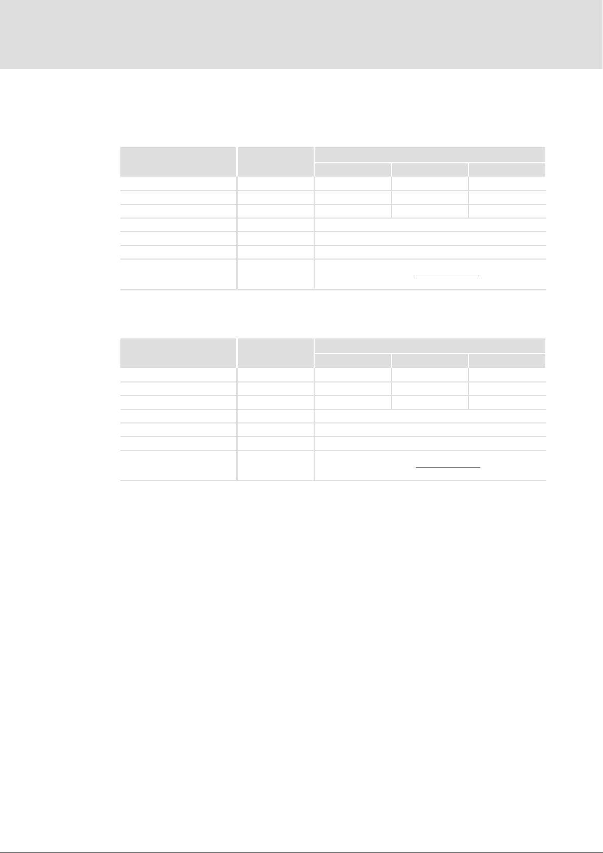
Brake resistors of type ERBD...
Brake resistors with an increased power loss in IP20 design (protection against accidental
contact acc. to NEMA 250 type 1)
3
P
Bmax
Brake resistor
HeatquantityQ
+
runningtime
B
Rated data Type
ERBD082R600W ERBD047R01K2 ERBD022R03K0
Resistance RB [Ω] 82 47 22
Continuous power Pd [W] 600 1200 3000
Heat quantity QB [kWs] 87 174 375
Max. running time te [s] 15
Required recovery time ta [s] 135
Operating voltage U
Max. braking power P
[VDC] 800
max
[kW]
Bmax
Brake resistors of type ERBS...
Brake resistors with an increased power loss in IP65 design (NEMA 250 type 4x)
P
Bmax
Brake resistor
HeatquantityQ
+
runningtime
B
Rated data Type
ERBS082R780W ERBS039R01K6 ERBS020R03K2
Resistance RB [Ω] 82 39 20
Continuous power Pd [W] 780 1640 3200
Heat quantity QB [kWs] 117 246 480
Max. running time te [s] 15
Required recovery time ta [s] 135
Operating voltage U
Max. braking power P
[VDC] 800
max
[kW]
Bmax
EDBCSXE040 EN 6.0
23
Page 24

4
Mechanical installation
Important notes
4 Mechanical installation
4.1 Important notes
ƒ ECSxE... power supply modules are provided with IP20 enclosure (NEMA 250 type 1)
and can therefore only be used for installation in control cabinets.
ƒ If the cooling air contains air pollutants (dust, fluff, grease, aggressive gases):
– Take suitable preventive measures , e.g. separate air duct, installation of filters,
regular cleaning.
ƒ Possible mounting positions
– Vertically at the mounting plate
– DC bus connections (X22) at the top
– Mains connection (X21) at the bottom
ƒ Maintain the specified clearances (above and below) to other installations!
– If the ECSZS000X0B shield mounting kit is used, an additional clearance is
required.
– Ensure unimpeded ventilation of cooling air and outlet of exhaust air.
– Several modules of the ECS series can be installed in the control cabinet next to
each other without any clearance.
ƒ The mounting plate of the control cabinet
– must be electrically conductive.
– must not be varnished.
ƒ In case of continuous vibrations or shocks use shock absorbers.
24
EDBCSXE040 EN 6.0
Page 25
Mechanical installation
Mounting with fixing rails (standard installation)
4.2 Mounting with fixing rails (standard installation)
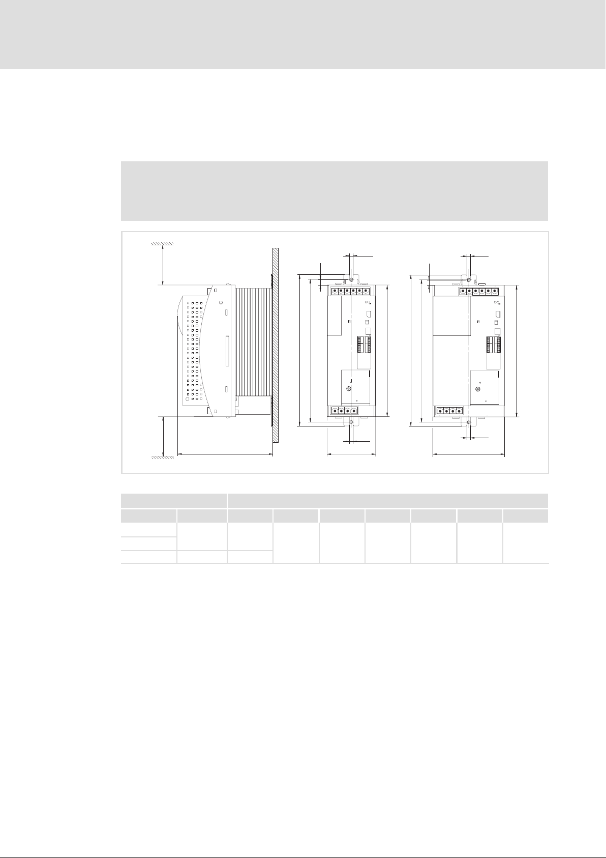
4.2.1 Dimensions
Note!
Mounting with ECSZS000X0B shield mounting kit:
ƒ Mounting clearance below the module > 195 mm
4
Dimensions
0
g
d
h
d1
176
212 1
³ 65 mm
³ 65 mm
Fig. 4−1 Dimensions for "panel−mounted" design
Power supply module Dimensions [mm]
Type Size a b d d1 e h g
ECSEE012
ECSEE020
ECSEE040 131
e
88.5
240 276 260
h
d
d1
a
b
g
1
g
g
a
)
10
b
ECSXA005
6.5
(M6)
1)
max. 212 mm, depending on the communication module attached
4.2.2 Mounting steps
Proceed as follows to mount the power supply module:
1. Prepare the fixing holes on the mounting surface.
– Use the drilling jig for this purpose.
2. Take the fixing rails from the accessory kit in the cardboard box.
3. Push the rails into the slots of the heatsink:
– From above: push in the long side.
– From below: push in the short side.
4. Attach the power supply module to the mounting surface.
EDBCSXE040 EN 6.0
25
Page 26

4
4.3 Mounting with thermal separation (push−through technique)
Mechanical installation
Mounting with thermal separation (push−through technique)
Mounting in push−through technique requires the rear panel of the control cabinet to be
a steel plate with a thickness of at least 3 mm.
The edges of the mounting cutout and the fixing holes for the clamps must be slightly
curved inwards (towards the power supply module).
Cooling
The separated heatsink serves to reduce the heat generation in the control cabinet.
ƒ Distribution of the power loss:
– approx. 65 % via separated cooler
– approx. 35 % inside the power supply module
ƒ Protection class of the separated cooler: IP54
– The sealing surface at the heatsink of the power supply module must rest
completely against the mounting plate.
– Use a liquid thread sealant to bond the screws of the clamps.
ƒ Cooling of the drive system:
– Air flow behind the rear panel of the control cabinet must be ³ 3 m/s (e.g. by means
of a collective fan).
ƒ With sufficient cooling, the ratings of the power supply modules remain valid.
26
EDBCSXE040 EN 6.0
Page 27
Mechanical installation
Mounting with thermal separation (push−through technique)
Dimensions
4
4.3.1 Dimensions
Note!
Mounting with ECSZS000X0B shield mounting kit:
ƒ Mounting clearance below the module > 195 mm
³ 65 mm
0
a1
g
b1
b
Z
h
d
b1
b
1
a1
g
Z
h
d
c1
³ 65 mm
Fig. 4−2 Dimensions for "push−through design"
Power supply module Dimensions [mm]
Type Size a a1 b b1 c1 d e e1 g h
ECSDE012
ECSDE020
ECSDE040 131 121.5
1)
max. 145 mm, depending on the communication module attached
e
Z Mounting cutout (a1 x b1), 28
e1
88.5 78.5
240 197 75 250
a
g
109
145
c1
a
67 M5 10.5
1)
g
ECSXA007
EDBCSXE040 EN 6.0
27
Page 28
4
Mechanical installation
Mounting with thermal separation (push−through technique)
Dimensions
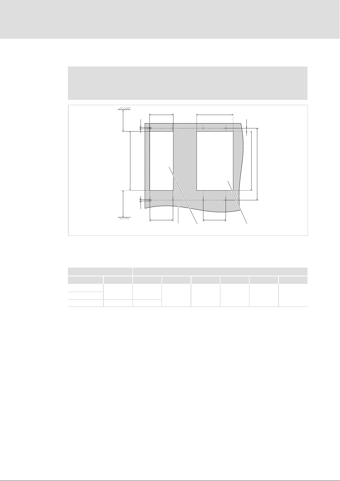
Dimensions of mounting cutout
Note!
Installation with shield mounting ECSZS000X0B:
ƒ Clearance below the mounting cutout > 220 mm
a1 a1
g
³ 70 mm
h
2
b1
d
b1
g
³ 90 mm
c1
0
Fig. 4−3 Dimensions of mounting cutout
Mounting surface
Mounting cutout for size
Mounting cutout for size
Power supply module Dimensions [mm]
Type Size a1 b1 c1 d g h
ECSDE012
ECSDE020
ECSDE040 121.5
78.5
197 75 250 M5 10.5
1
c1
ECSXA063
28
EDBCSXE040 EN 6.0
Page 29

Mechanical installation
Mounting with thermal separation (push−through technique)
Mounting steps
4
4.3.2 Mounting steps
Proceed as follows to mount the power supply module:
1. Prepare the fixing holes for the clamps on the mounting surface.
– Use the drilling jig for this purpose.
2. Prepare the mounting cutout.
– The edges of the mounting cutout and the fixing holes for the clamps must be
slightly curved inwards (towards the power supply module).
3. Apply liquid thread sealant to the threads of the screws for the wire clamps.
4. Fix the clamps.
5. Push the power supply module into the mounting cutout.
6. Let the power supply module snap into the clamps at the top and at the bottom.
EDBCSXE040 EN 6.0
29
Page 30

4
Mechanical installation
Mounting in cold−plate design
4.4 Mounting in cold−plate design
The ECSCE series power supply modules are intended for mounting in cold plate technique
(e.g. on collective coolers).
Requirements for collective coolers
The following requirements must be met to ensure safe and reliable operation of the
power supply modules:
ƒ Good thermal contact with the cooler:
– The contact surface between collective cooler and power supply module must be
at least as large as the cooling plate of the power supply module.
– Smooth contact surface, max. deviation 0.05 mm.
– Use all prescribed screwed connections to connect the collective cooler to the
power supply module.
ƒ Comply with the thermal resistance R
according to the table.
th
– The values are valid for operation of the power supply modules under rated
conditions.
Power supply
module
Type Ploss [W] Rth [k/W]
ECSCE012 30.0 0.45
ECSCE020 45.0 0.34
ECSCE040 81.0 0.17
ƒ Ambient conditions:
Power to be dissipated Heatsink ˘ environment
– The rated data regarding the ambient temperature remain valid for the power
supply modules ( 19 ff.).
– Temperature of the cooling plate ("cold plate"): max. +85 °C
30
EDBCSXE040 EN 6.0
Page 31
Mechanical installation
Mounting in cold−plate design
Dimensions
4
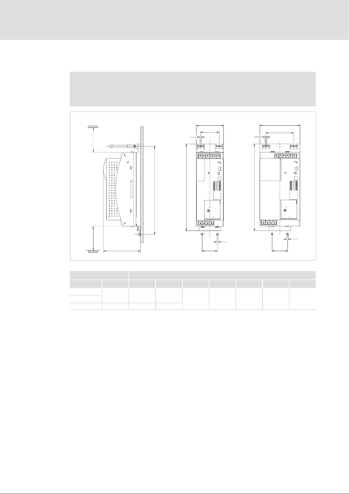
4.4.1 Dimensions
Note!
Mounting with ECSZS000X0B shield mounting kit:
ƒ Mounting clearance below the module > 195 mm
³ 65 mm
0
a
g
d
b
a1
g
b
1
a
a1
g
³ 65 mm
Fig. 4−4 Dimensions for "cold−plate design"
Power supply module Dimensions [mm]
Type Size a a1 b c1 d e g
ECSCE012
ECSCE020
ECSCE040
1)
Max. 157 mm, depending on the plugged−on communication module
e
131 90
88.5 60
c1
282 50 287
121
157
g
c1
1)
ECSXA009
M6
EDBCSXE040 EN 6.0
31
Page 32
4
Mechanical installation
Mounting in cold−plate design
Mounting steps
4.4.2 Mounting steps
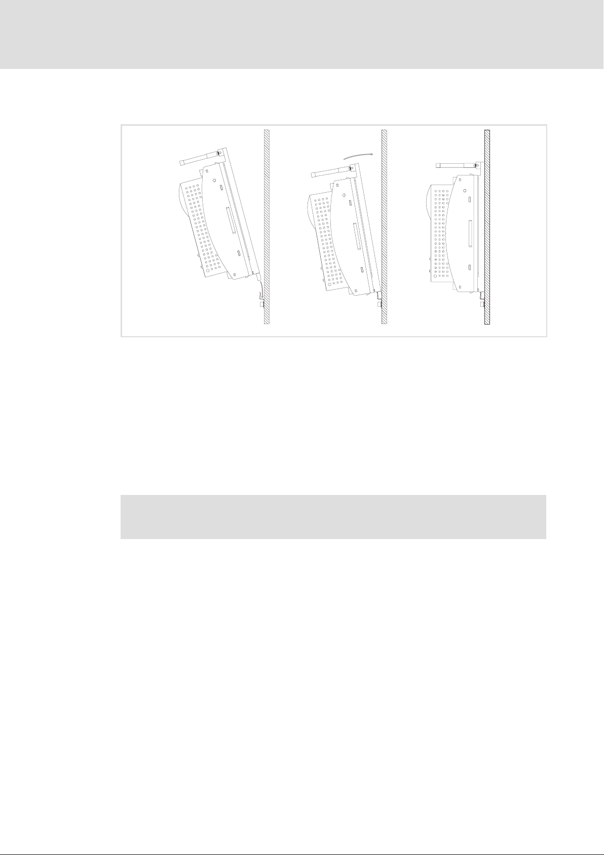
Fig. 4−5 Mounting for "cold−plate design"
Proceed as follows to mount the power supply module:
1. Prepare the fixing holes on the mounting surface.
– Use the drilling jig for this purpose.
À Á Â
ECSXA030
2. Clean and degrease the contact areas of the collective cooler and the power supply
module’s cooling plate (e.g. with methylated spirit).
3. Screw the support onto the collective cooler.
4. Push the power supply module from above into the support and tighten both
studs with 3.5 ... 4.5 Nm .
Note!
Penetration depth of the screws into the collective cooler: approx. 15 mm!
Tip!
The heat transfer resistance is reduced if − following step 2. −
ƒ a thin layer of heat conducting paste is applied to the contact surface or
ƒ heat conducting foil is used.
32
EDBCSXE040 EN 6.0
Page 33

Electrical installation
Installation according to EMC (installation of a CE−typical drive system)
5 Electrical installation
5.1 Installation according to EMC (installation of a CE−typical drive system)
General information
ƒ The electromagnetic compatibility of a machine depends on the type of installation
and care taken. Especially consider the following:
– Assembly
– Filters
– Shielding
– Earthing
ƒ For diverging installations, the evaluation of the conformity to the EMC Directive
requires a check of the machine or system regarding the EMC limit values. This for
instance applies to:
– Use of unshielded cables
– Use of collective interference filters instead of the assigned RFI filters
– Operation without RFI filters
5
ƒ The compliance of the machine application with the EMC Directive is in the
responsibility of the user.
– If you observe the following measures, you can assume that the machine will
operate without any EMC problems caused by the drive system, and that
compliance with the EMC Directive and the EMC law is achieved.
– If devices which do not comply with the CE requirements concerning noise
immunity EN 61000−6−2 are operated close to the axis modules, these devices may
be electromagnetically affected by the axis modules.
EDBCSXE040 EN 6.0
33
Page 34

5
Electrical installation
Installation according to EMC (installation of a CE−typical drive system)
Assembly
ƒ Connect the power supply modules, capacitor modules (optional), axis modules, RFI
filters, and mains chokes to the earthed mounting plate with a surface as large as
possible.
– Mounting plates with conductive surfaces (zinc−coated or stainless steel) allow
permanent contact.
– Painted plates are not suitable for an EMC−compliant installation.
ƒ If you use the ECSxK... capacitor module:
– Install the capacitor module between the power supply module and the axis
module(s).
– If the total cable length in the DC−bus connection is > 5 m, install the capacitor
module as close as possible to the axis module with the greatest power.
ƒ Use of several mounting plates:
– Connect as much surface of the mounting plates as possible (e.g. with copper
bands).
ƒ Ensure the separation of motor cable and signal or mains cables.
ƒ Avoid a common terminal/power strip for the mains input and motor output.
ƒ Lay the cables as close as possible to the reference potential. Freely suspended
cables act like aerials.
Filters
Only use RFI filters and mains chokes which are assigned to the power supply modules:
ƒ RFI filters reduce impermissible high−frequency interferences to a permissible value.
ƒ Mains chokes reduce low−frequency interferences which depend on the motor
cables and their lengths.
34
EDBCSXE040 EN 6.0
Page 35

Electrical installation
Installation according to EMC (installation of a CE−typical drive system)
Shielding
ƒ Connect the motor cable shield to the axis module
– with the ECSZS000X0B shield mounting kit.
– to the mounting plate below the axis module with a large surface.
– Recommendation: For the shield connection, use ground clamps on bare metal
mounting surfaces.
ƒ If contactors, motor−protecting switches or terminals are located in the motor cable:
– Connect the shields of the connected cables and connect the shields to the
mounting plate, too, with a surface as large as possible.
ƒ Connect the shield in the motor terminal box or on the motor housing to PE:
– Metal glands at the motor terminal box ensure a large−surface connection of the
shield and the motor housing.
ƒ Shield the control cables:
– Connect both shield ends of the digital control cables.
– Connect one shield end of the analog control cables.
– Always connect the shields to the shield connection at the axis module over the
shortest possible distance.
5
ƒ Using the axis modules in residential areas:
– Additionally dampen the shield in order to limit the interfering radiation: ³10 dB .
This can be implemented by using standard, closed, metallic, and earthed control
cabinets or boxes.
Earthing
ƒ Earth all metallically conductive components (e. g. power supply module, capacitor
module, axis module, RFI filter, motor filter, mains choke) using suitable cables
connected to a central point (PE bar).
ƒ Maintain the minimum cross−sections prescribed in the safety regulations:
– For the EMC, not the cable cross−section is important, but the cable surface and the
contact surface which should be as large as possible.
EDBCSXE040 EN 6.0
35
Page 36
5
Electrical installation
Drive system on the mains
Electrical isolation
5.2 Drive system on the mains
This information applies to the ECS drive system, consisting of:
ƒ ECSxE... power supply module
ƒ ECSxK series capacitor module (optional)
ƒ ECSxS/P/M/A series axis module
ƒ Motor
ƒ Accessories
ƒ Wiring
5.2.1 Electrical isolation
The integrated electrical isolation between the power section and the control section is a
protective separation (reinforced insulation) acc. to EN 61800−5−1.
To maintain this protective separation, it must be ensured that the external 24 V supply
and all components connected to this supply also have a protective separation (SELV/PELV)
acc. to EN 61800−5−1.
24 V supply DC bus
X6/+24, GND X22
Dig. input/output
X6/DI1, DI2, D24, DO1
Thermostat
X6/T1, T2
CAN
X4 Mains
AIF
X1
Fig. 5−1 Electrical isolation
X21
Basic insulation (50 V)
Reinforced insulation
(300 V)
36
EDBCSXE040 EN 6.0
Page 37

Supply forms / electrical supply conditions
5.2.2 Supply forms / electrical supply conditions
Stop!
The power supply module may only be operated on balanced mains supplies.
Operation on mains supplies with earthed phase is not permitted.
The ECSxE series power supply modules are provided with an automatic detection of the
mains voltage and adapt the brake chopper switch−on voltage.
Please observe the restrictions for the respective supply forms:
Mains Operation of the power supply modules Notes
With earthed neutral
(TT/TN systems)
With isolated neutral
(IT systems)
No restrictions Observe the rated data of the power supply
The ECSxExxxx4I IT variant can be used if
the power supply module is protected in
the event of an earth fault in the mains
supply:
l by suitable equipment detecting the
earth fault.
l by disconnecting the power supply
module immediately from the mains.
Electrical installation
Drive system on the mains
modules.
In the event of an earth fault at the output
of the power supply module, safe operation
cannot be guaranteed.
5
Note!
ƒ Mains voltage dips can be reduced by decreasing the max. charging current
limit (C0022).
ƒ Deactivate the charging current limitation (charge relay) of the connected
ECS axis modules with C0175 = 3.
5.2.3 Operation on public supply systems (compliance with EN 61000−3−2)
The European Standard EN 61000−3−2 determines limit values for limiting harmonic
currents in the supply system. Non−linear loads (e.g. frequency inverters) produce
harmonic currents which may "pollute" the supply system and thus have an impact on
other consumers.The standard wants to ensure the quality of the public supply system and
reduce the mains load.
Note!
The standard only applies to public supply systems. Supply systems which
have their own transformer substation as common in industry are not public.
The standard does not apply to them.
If a device or machine consists of several components, the limit values of the
standard apply to the entire unit.
EDBCSXE040 EN 6.0
37
Page 38

5
Electrical installation
Power terminals
5.3 Power terminals
Danger!
Stop!
Dangerous voltage
The leakage current to earth (PE) is > 3.5 mA AC or > 10 mA DC.
Possible consequences:
ƒ Death or severe injuries when the device is touched in the event of a fault.
Protective measures:
ƒ Implement the actions required in the EN 61800−5−1. Especially:
– Fixed installation
– PE connection must conform to standards (PE conductor diameter
³ 10 mm
2
or PE conductor must be connected twice)
No device protection if the mains voltage is too high
The mains input is not internally fused.
Possible consequences:
ƒ Destruction of the device if the mains voltage is too high.
Protective measures:
ƒ Observe the maximally permissible mains voltage.
ƒ Fuse the device correctly on the supply side against mains fluctuations and
voltage peaks.
ƒ All power connections are plug connections and are coded. The connector set for the
ECSZE000X0B power supply modules must be ordered separately.
ƒ Installation of cables acc. to EN 60204−1.
ƒ The cables used must comply with the approvals required for the respective
application (e.g. VDE, UL, etc.).
Assignment of the plug connectors
Terminal Function Electrical data
X21 Mains connection
X21/L1 Mains phase L1
X21/L2
X21/L3 Mains phase L3
X21/PE Connection of PE conductor
X22 DC−bus voltage connection
X22/BR0
X22/BR1
X22/+UG
X22/+UG
X22/−UG
X22/PE
Mains phase L2
Internal brake resistor, connection 1
External brake resistor, connection 1
Internal/external brake resistor, connection 2
DC−bus voltage supply, plus
DC−bus voltage supply, minus
Connection of PE conductor
Dependent on application and type
0 ... 480 V
up to 31.3 A ( 21)
Dependent on application and type
0 ... 770 V
up to 38.5 A ( 21)
38
EDBCSXE040 EN 6.0
Page 39

Electrical installation
Cable cross−sections and screw−tightening torques
5
Power terminals
Cable type Wire end ferrule Possible cable
Terminal strips X21 and X22
Rigid ˘
Without wire end
ferrule
Flexible
With insulated wire
end ferrule
With insulated TWIN
wire end ferrule
cross−sections
0.2 ... 10 mm
(AWG 24 ... 8)
0.2 ... 10 mm
(AWG 24 ... 8)
0.25 ... 6 mm
(AWG 22 ... 10)
0.25 ... 4 mm
(AWG 22 ... 12)
Tightening torque Stripping length
2
2
2
2
1.2 ... 1.5 Nm
(10.6 ... 13.3 lb−in)
5 mm for screw
connection
10 mm for spring
connection
Shielded cables
The following factors decisively determine the effect of the shielded cables:
ƒ Good shield connection
– Ensure a contact surface as large as possible
ƒ Low shield resistance
– Only use shields with tin−plated or nickel−plated copper braids (shields with steel
braids cannot be used).
ƒ High overlap rate of the braid
– At least 70 ... 80 % with 90° overlap angle
The ECSZS000X0B shield mounting kit includes a wire clamp and shield sheet.
EDBCSXE040 EN 6.0
39
Page 40

5
Electrical installation
Power terminals
Mains connection
5.3.1 Mains connection
Important notes
ƒ Keep the cables between the RFI filter and the power supply module as short as
possible.
– Make sure that no short−circuit can occur!
ƒ Mains cables and ±U
ƒ When mains cables and ±U
– Cable distance: > 150 mm
ƒ Cable length > 30 cm:
– Shield the cables between the RFI filter and the power supply module to comply
with the general EMC Directive.
ƒ With some 24 V switched−mode power supplies, the EMC limit values for the system
will only be met if the power supplies are connected to ECSZZ series RFI filters.
Please contact the manufacturer of the power supply unit on the compliance with
EMC limit values for conducted interference.
You must observe ...
the notes in the documentation on the ECSZZ series RFI filter!
cables must not contact each other.
G
cables are laid in parallel:
G
Wiring variants for the ECSxE power supply module
3
44
1
00
3
Fig. 5−2 Wiring variants for the ECSxE power supply module
Simple wiring
/
Wiring with mains chokes
Wiring with RFI filters
Power supply module ECSxE
Mains choke
RFI filter
Wiring of components
Mains cable
4
4
02
2
0
3
3
4
1
02
3
ECSxE040
40
EDBCSXE040 EN 6.0
Page 41

Electrical installation
Power terminals
Mains connection
Fuses
Use the following circuit−breakers or UL−approved fuses to protect the mains cable:
5
Power supply
module
ECSxE012
ECSxE020
ECSxE040
:
/:
,
:
:
Circuit−breaker Cable cross−section
1) Cable without wire end ferrule or with pin−end connector
2) Cable length max. 30 cm
Dimensioning to VDE Dimensioning to UL
C16 A 2.5 25A 12
C16 A 2.5 25A 12
C 40 A 10
C 32 A 6 35 A 10
C 40 A 6
C 40 A 10 35 A 8
Warnings!
ƒ Use UL−approved cables, fuses and fuse holders only.
ƒ UL fuse:
– Voltage 500 ... 600 V
– Tripping characteristic "H", "K5" or "CC"
Replacing defective fuses
[mm
2
]
1)
2)
UL fuse AWG
35 A 8
35 A 10
1)
2)
Danger!
Hazardous electrical voltage
Components can carry hazardous voltages up to 3 minutes after power−off.
Possible consequences:
ƒ Death or severe injuries when touching the device.
Protective measures:
ƒ Replace fuses in the deenergised state only.
– Set controller inhibit (CINH) for all axis modules in DC−bus operation and
disconnect all power supply modules from the mains.
EDBCSXE040 EN 6.0
41
Page 42

5
Electrical installation
Power terminals
Connection to the DC bus (+U
, −UG)
G
5.3.2 Connection to the DC bus (+UG, −UG)
Stop!
ƒ The supply of Lenze controllers of the 82xx and 93xx series is not permitted.
ƒ If synchronous motors with a high centrifugal mass are used, a considerable
amount of energy can be fed back into the DC bus. Please take this into
account when dimensioning the brake resistor.
ƒ If the total cable length is > 20 m, install an axis module or a capacitor module
directly at the power supply module.
ƒ Design the ±U
routing!
ƒ Cable length (module « module) > 30 cm: install shielded ±U
Fuses
Fusing the DC−bus interconnection is not required if power supply modules of the ECS
series are used which are fused on the mains side.
Cable cross−sections
Cable
length (modu
le/module)
Up to 20 m
> 20 m
Wire end ferrule Cable cross−section Tightening torque Stripping length
Without wire end
ferrule
With insulated wire end
ferrule
Without wire end
ferrule
With insulated wire end
ferrule
Use pin−end connectors
for wiring!
cables twisted and as short as possible. Ensure short−circuit−proof
G
2
6 mm
(AWG 10)
10 mm
(AWG 8)
cables.
G
5 mm for screw
1.2 ... 1.5 Nm
(10.6 ... 13.3 lb−in)
2
connection
10 mm for spring
connection
42
EDBCSXE040 EN 6.0
Page 43
Electrical installation
Power terminals
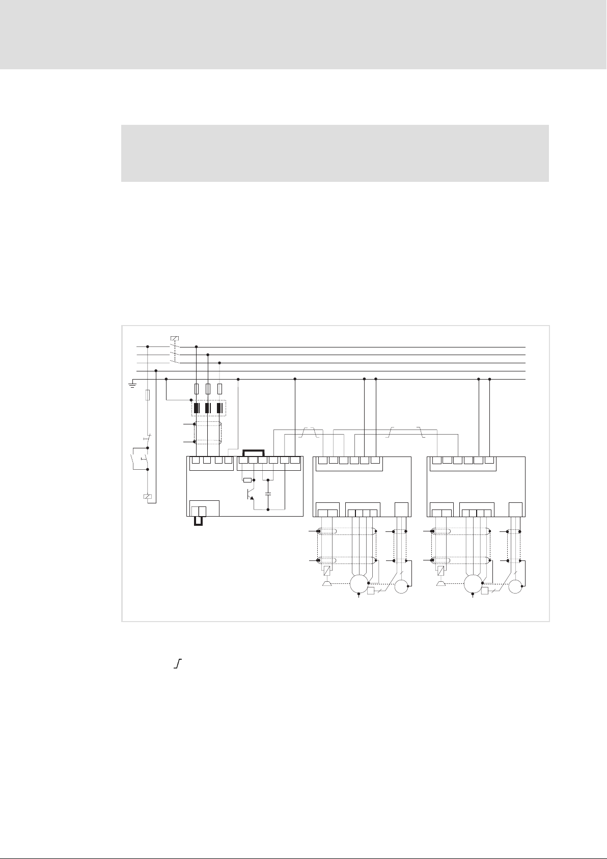
Connection plan for mimimum wiring with internal brake resistor
5
5.3.3 Connection plan for mimimum wiring with internal brake resistor
Stop!
Always operate the ECS power supply modules with a brake resistor
(internal/external).
The ECS power supply modules in the standard built−in unit and push−through design
(ECSEE / ECSDE) are provided with a device−internal brake resistor.
In order to use the internal brake resistor (Rb), carry out the following wiring:
ƒ Bridge between the terminals X22/+UG and X22/BR0 (CR)
Current flow from +UG via the internal brake resistor (Rb) and the brake transistor to
−UG.
ƒ Bridge between the terminals X6/T1 and X6/T2 (CR)
Deactivate the temperature monitoring of the non−existing external brake resistor.
K1
L1
L2
L3
N
F4
Off
On
K1
K1
F1...F3
Z1
"
"
L3
L1 L2
PE
X21
ECSEE...
ECSDE...
X6
...
T1
T2
BR1
Rb
-UG
X22
+UG
+UG
PE
-UG
PE
-UG
X23
ECSxS/P/M/A...
BD1
X25
BD2
UV
X24
W
X7
PE
PE
+UG
BR0
+UG
0
"
"
"
+UG
+UG
-UG
X23
PE
-UG
PE
ECSxS/P/M/A...
BD2
UV
X24
PE
W
BD1
X25
"
X7
0
EDBCSXE040 EN 6.0
"
M
3~
J
2
+
Fig. 5−3 Interconnected power system with internal brake resistor
HF−shield termination by large surface connection to functional earth (see mounting
instructions for shield mounting ECSZS000X0B)
Twisted cables
K1 Mains contactor
F1 ... F4 Fuse
Z1 Mains choke / mains filter, optional
Rb Internal brake resistor
J KTY thermal sensor of the motor
System cable for feedback
"
"
6
R
"
M
3~
J
6
R
2
+
ECSXA011
43
Page 44

5
5.3.4 Connection plan for mimimum wiring with external brake resistor
Electrical installation
Power terminals
Connection plan for mimimum wiring with external brake resistor
Stop!
ƒ Always operate the ECS power supply modules with a brake resistor.
ƒ A parallel wiring of internal and external brake resistor is not permissible!
ƒ Implement the thermal contact of the brake resistor into the system
monitoring so that the mains supply of the power supply module will be
switched off in case the brake resistor will be overheated.
ƒ Read the documentation for the external brake resistor. Observe the safety
instructions contained therein.
If the power supply module needs a high amount of braking power when it comes as
standard built−in unit or in push−through technique design (ECSEE / ECSDE), an external
and more powerful brake resistor can be connected instead of the internal brake resistor.
A power supply module in cold plate technique design (ECSCE) is not provided with an
internal brake resistor so that this version always requires an external brake resistor
(Rbext).
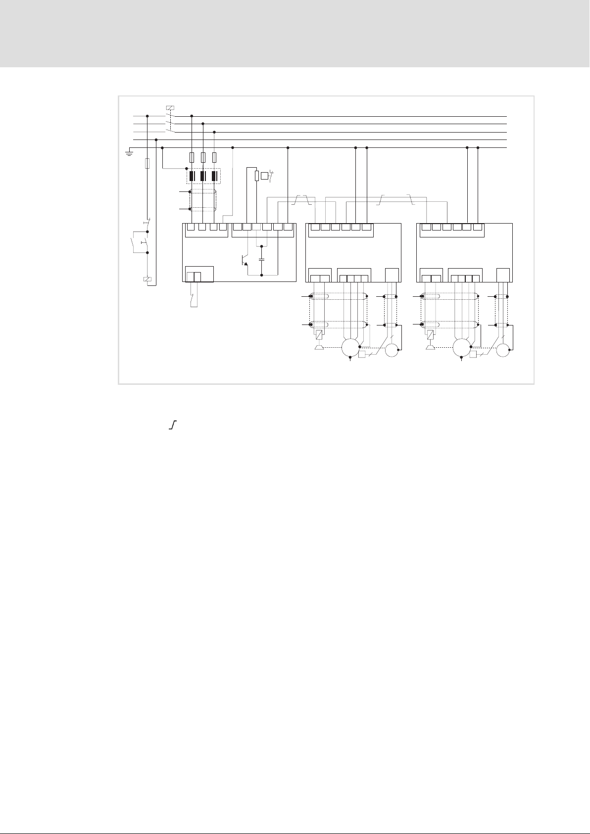
ƒ Connect the brake resistor to X22/BR1 and X22/+UG.
ƒ Connect the thermal contact (NC contact) of the external brake resistor to X6/T1
and X6/T2.
44
EDBCSXE040 EN 6.0
Page 45
Electrical installation
5
Power terminals
Connection plan for mimimum wiring with external brake resistor
K1
L1
L2
L3
N
F4
F1...F3
Z1
Rb
ext
J
"
Off
On
K1
K1
"
J
(Rb
L1 L2
X21
ECSxE...
X6
...
T1
T2
)
ext
L3
PE
BR0
+UG
BR1
+UG
PE
-UG
X22
+UG
+UG
PE
-UG
PE
-UG
X23
ECSxS/P/M/A...
BD2
UV
X24
PE
W
"
"
M
3~
J
2
"
"
BD1
X25
+
Fig. 5−4 Interconnected power system with external brake resistor
HF−shield termination by large surface connection to functional earth (see mounting
K1 Mains contactor
F1 ... F4 Fuse
Z1 Mains choke / mains filter, optional
Rb
J KTY thermal sensor of the motor
System cable for feedback
instructions for shield mounting ECSZS000X0B)
Twisted cables
External brake resistor
ext
+UG
+UG
-UG
X23
PE
-UG
PE
ECSxS/P/M/A...
X7
BD1
X25
BD2
UV
X24
W
0
"
"
6
R
M
3~
X7
PE
0
"
"
6
J
R
2
+
ECSXA012
EDBCSXE040 EN 6.0
45
Page 46
5
Electrical installation
Power terminals
Connection plan for mimimum wiring with external brake resistor
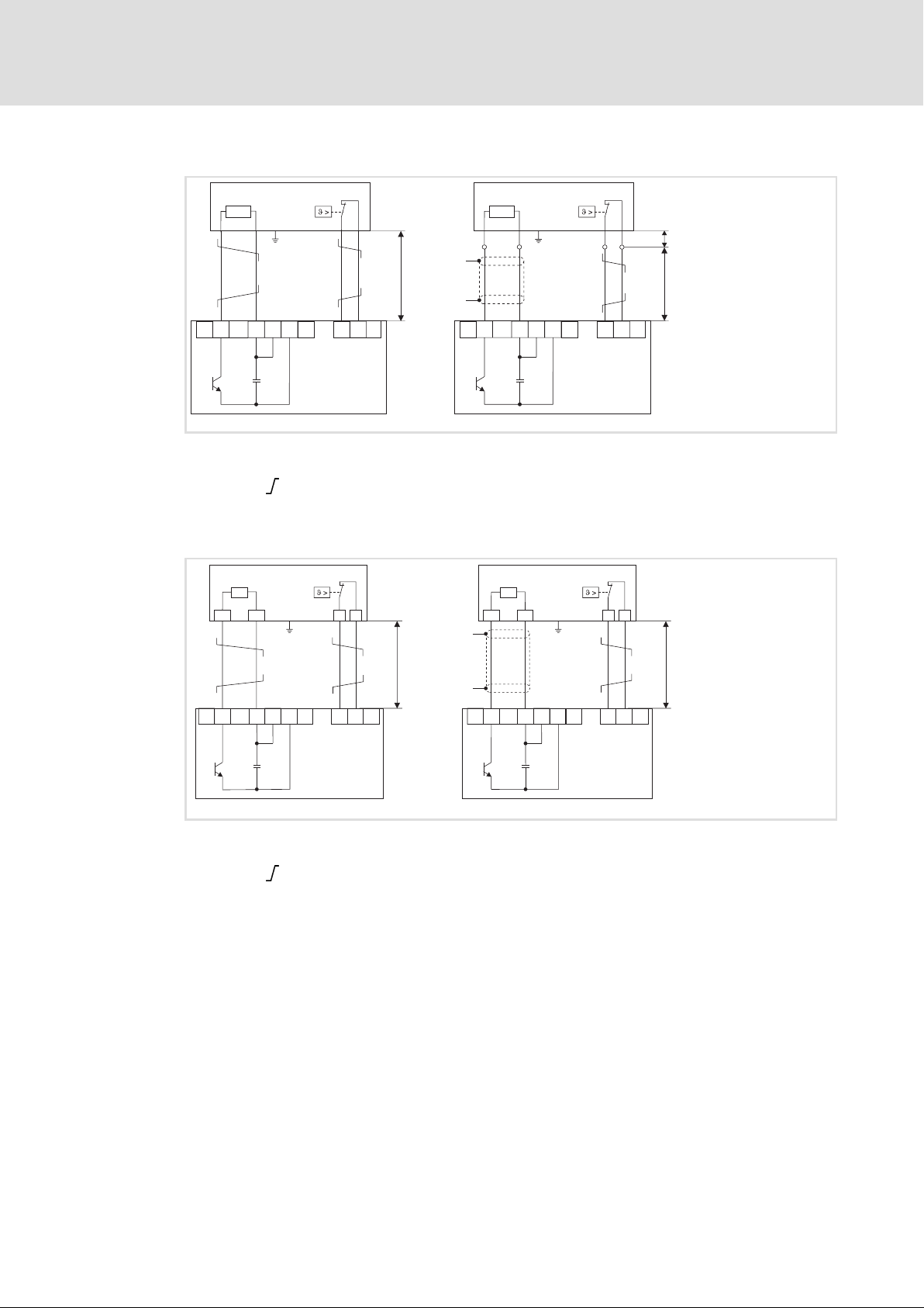
Wiring of external brake resistor ERBM...
ERBM...
R
B_ext
PE
ERBM...
R
B_ext
PE
"
< 0.5 m
"
BR0
BR1
X22
+UG
+UG
-UG
PE
T1
X6
ECSCE...
T2
BR0
BR1
X22
+UG
+UG
-UG
PE
ECSCE...
…
Fig. 5−5 Connection of external brake resistors, ERBM series
HF−shield termination by large surface PE connection
Twisted cables
Wiring of external brake resistor of ERBS.../ERBD... series
ERBS... / ERBD...
R
B
RB1 RB2 T1 T2
PE
"
ERBS... / ERBD...
R
B
RB1 RB2 T1 T2
PE
<10cm
<5m
…
T2
T1
X6
ECSXE011
< 0.5 m
"
BR0
BR1
X22
+UG
+UG -UG
PE
T1
ECSxE...
…
T2
X6
BR0
Fig. 5−6 Wiring of external brake resistor, ERBS.../ERBD... series
HF−shield termination by large surface PE connection
Twisted cables
BR1
X22
+UG
+UG -UG
PE
T1
ECSxE...
<5m
…
T2
X6
ECSXE010
46
EDBCSXE040 EN 6.0
Page 47
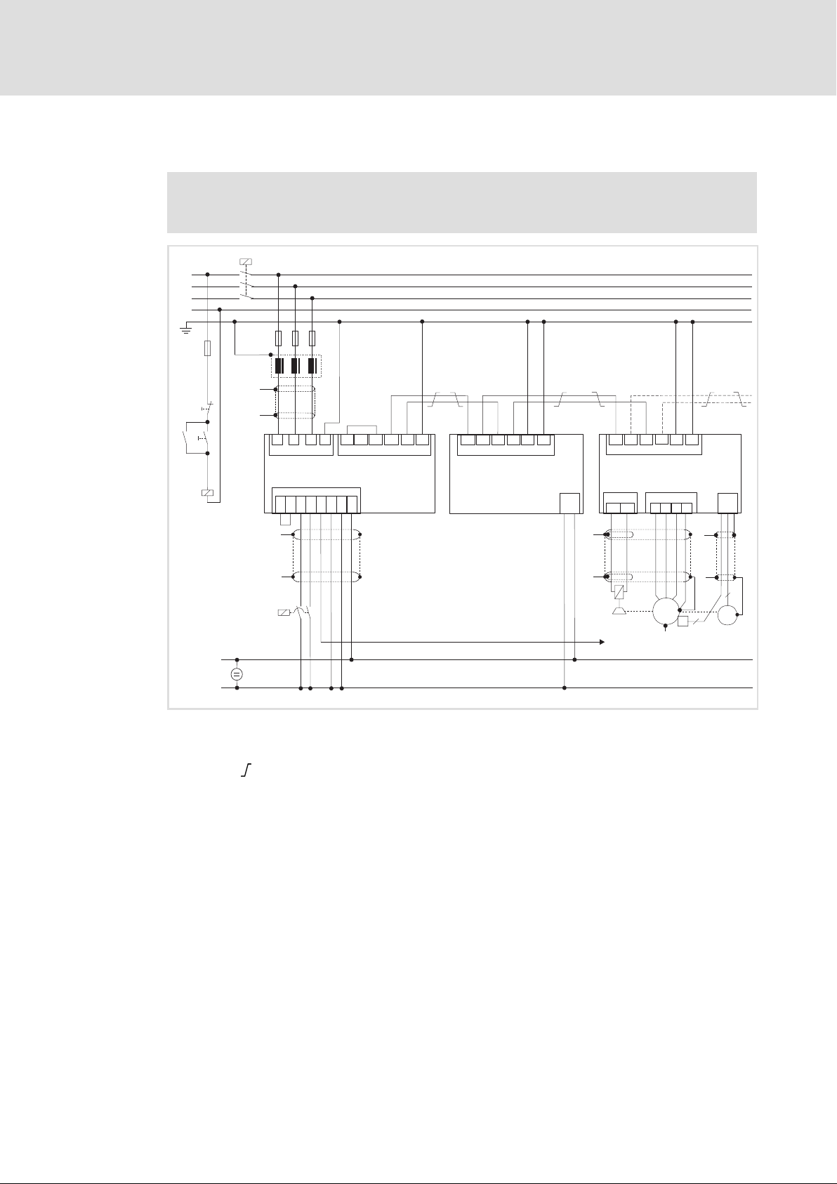
Electrical installation
Power terminals
Connection of an ECSxK... capacitor module (optional)
5
5.3.5 Connection of an ECSxK... capacitor module (optional)
Observe...
the notes in the detailed documentation of the capacitor module.
K1
L1
L2
L3
N
F4
Off
On
K1
K1
F1...F3
Z1
"
"
L1 L2
T1
"
L3
X21
T2
DI1
PE
BR0
ECSxE...
X6
DI2
DO1
D24
+24V
BR1
GND
+UG
X22
+UG
-UG
PE
+UG
+UG
-UG
-UG
X23
ECSxK...
-UG
-UG
+UG
PE
PE
+UG
X23
PE
PE
ECSxS/P/M/A...
X26
BD1
X25
BD2
UV
X24
W
X7
PE
1
"
"
"
0
GND
-
24VDC
Fig. 5−7 Wiring of capacitor module ECSxK...
+
HF−shield termination by large−surface connection to functional earth (see Mounting
Instructions for ECSZS000X0B shield mounting kit)
Twisted cables
K1 Mains contactor
F1 ... F4 Fuse
Z1 Mains choke / mains filter, optional
Contactor relay
System cable ˘ feedback
Terminal X6/SI1 of the connected axis modules (controller enable/inhibit)
"
"
M
3~
J
2
+
6
R
2
ECSXX004
EDBCSXE040 EN 6.0
47
Page 48
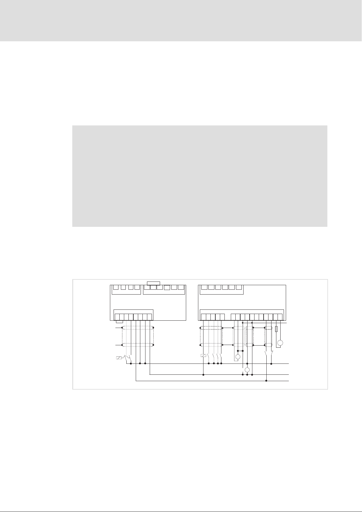
5
Electrical installation
Control terminals
5.4 Control terminals
ƒ The supply of the control electronics requires an external 24 V DC voltage at
terminals X6/+24 and X6/GND.
ƒ Connect the thermal detector of an external brake resistor to the terminals X6/T1
and X6/T2. If no external brake resistor is required, jumper terminals X6/T1 and
X6/T2.
Stop!
ƒ The control cables must always be shielded to prevent interference
injections.
ƒ The voltage difference between X6/AG, X6/GND and PE of the axis module
may maximally amount to 50 V.
ƒ The voltage difference can be limited by:
– overvoltage−limiting components or
– direct connection of X6/AG and X6/GND to PE.
ƒ The wiring has to ensure that for X6/DO1 = 0 (LOW level) the connected axis
modules do not draw energy from the DC bus. Otherwise, the power supply
module may be damaged.
Shield connection of control cables and signal cables
The plate on the front of the device serves as the mounting place (two threaded holes M4)
for the shield connection of the signal cables. The screws used may extend into the inside
of the device by up to 10 mm. For optimum contact of the shield connection, use the wire
clamps from the ECSZS000X0B shield mounting kit.
+UG
L3
PE
BR0
L1 L2
X21
BR1
ECSxE...
X6
+24V
DI1
DI2
T1
T2
GND
DO1
D24
"
"
0
Fig. 5−8 Interconnection: Control signals with internal brake resistor
HF−shield termination by large surface connection to functional earth (see mounting
/ Contactor relay
Voltage supply of motor holding brake 23 ... 30 V DC, max. 1.5 A
Safe torque off (formerly: "Safe standstill")
Controller enable/inhibit
instructions for shield mounting ECSZS000X0B)
X22
+UG
-UG
PE
+24 VDC
GND
+UG
X23
-UG-UG
PEPE
+UG
ECSxS/P/M/A...
X6
DI4
"
"
AI-
AI+
=
24 VDC
AG
+24V
GND
SO
S24
"
"
-
+
+
=
-
DI1
DI2
DI3
DO1
1
4
B-
B+
SI1
SI2
"
F1,6A
U
2
3
ECSXA013
48
EDBCSXE040 EN 6.0
Page 49

Electrical installation
Control terminals
Switch−on sequence for the auxiliary relay
Stop!
Overload of the charging connection in the power supply module
The controller enable for the axes may only take place when the charging
process of the DC bus is completed and the power supply module is ready for
operation.
Possible consequences:
ƒ Destruction of the power supply module
Protective measures:
ƒ Use of switching the central controller enable for the axes via the inputs and
outputs DI2 and DO1 of the power supply module (see the following
descriptions).
The switch−on sequence of the auxiliary relay (see Fig. 5−8) is as follows:
1. The digital input X6/DI1 (power supply enable) of the power supply module is
switched to HIGH by the higher−level control or by the operator.
– The DC bus is charged.
5
2. The ready for operation output of the axis module (DO1) now switches the X6/DI2
digital input (central controller enable) of the power supply module via the relay .
– In the default Lenze setting of the ECS axis modules, DO1 is set to "ready". "Ready"
is only present if a specified DC−bus voltage has been reached.
3. The central controller enable for the axis module takes place via the X6/DO1 output
of the power supply module. The central controller enable DO1 only switches if the
charging process of the DC bus is completed AND the X6/DI2 input is set.
EDBCSXE040 EN 6.0
49
Page 50
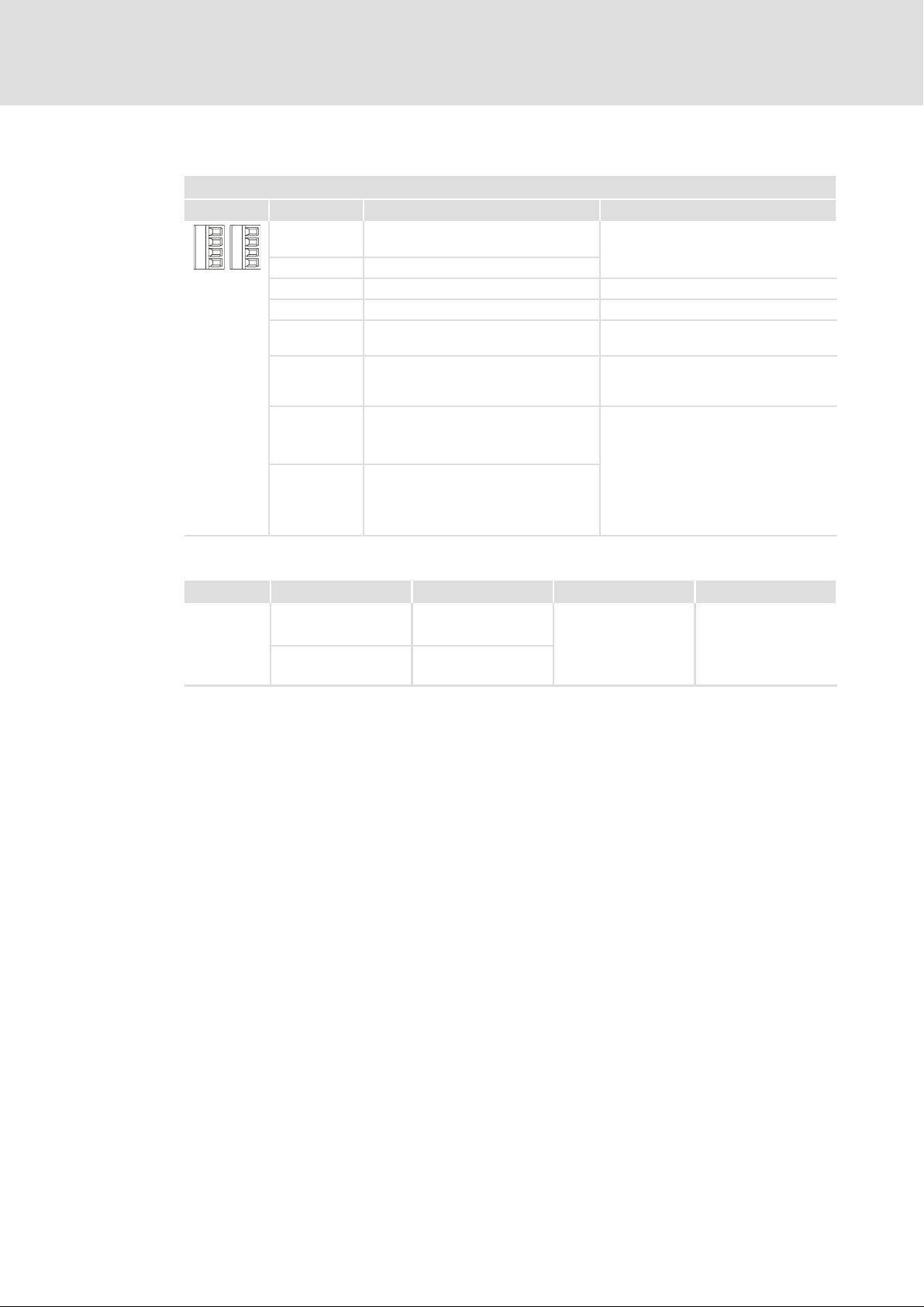
5
Electrical installation
Control terminals
Assignment of the plug connectors
Terminal strip X6
View Terminal Function Electrical data
X6/+24 Low−voltage supply of control
+24
T1 DO1 DI2 DI1
T2 D24 GND
X6/GND Reference potential low−voltage supply
X6/T1 Thermostat contact 1
X6/T2 Thermostat contact 2
X6/D24 Low−voltage supply X6/DO1 (digital
X6/DO1 Digital output 1
X6/DI1 Digital input 1
X6/DI2 Digital input 2
electronics
output 1)
(for central controller enable signal to
connected axis modules)
(for power supply enable/charge of the
DC bus)
(for central controller enable signal to
connected modules; available at output
X6/DO1)
20 ... 30 V DC, 0.5 A (max. 1 A)
for 24 V starting current:
max. 2 A for 50 ms
18 ... 30 V DC
24 V DC, 0.7 A (max. 1.4 A)
short−circuit−proof
LOW:
−3 ... +5 V;
−3 ... +1.5 mA
HIGH:
+15 ... +30 V;
+2 ... +15 mA
Input current at 24 V DC:
8 mA per input
Cable cross−sections and screw−tightening torques
Cable type Wire end ferrule Cable cross−section Tightening torque Stripping length
Flexible
Without wire end
ferrule
With insulated wire
end ferrule
0.08 ... 1.5 mm
(AWG 28 ... 16)
0.25 ... 0.5 mm
(AWG 22 ... 20)
2
0.22 ... 0.25 Nm
2
(1.95 ... 2.2 lb−in)
5 mm for screw
connection
9 mm for spring
connection
We recommend to use control cables with a cable cross−section of 0.25 mm2.
50
EDBCSXE040 EN 6.0
Page 51

5.4.1 Digital inputs and outputs
Stop!
If an inductive load is connected to X6/DO1, a spark suppressor with a limiting
function to max. 50 V ± 0 % must be provided.
Power supply enable of the power supply module
ƒ The X6/DI1 input serves to start the controlled charge of the DC bus by the charging
thyristor.
ƒ Only when the charging process is completed, which is displayed through the ready
for operation message at the X6/DO1 output of the power supply module, the
connected axis modules may be enabled. Otherwise, the charging thyristor would be
overloaded.
X6/DI2 − central controller enable for the connected axis modules via DO1
ƒ The X6/DI2 input can be used together with the X6/DO1 output as centrally
controlled controller enable for all connected axes. The DO1 output only switched if
the DC bus has been charged completely without any trouble. This automatically
ensures that the axis modules cannot be enabled too early and consume energy
from the DC bus too early.
Electrical installation
Control terminals
Digital inputs and outputs
5
ƒ For this purpose, wire the X6/DO1 output with the X6/SI1 inputs of the axis
modules for controller enable.
If required, one further contact can be connected in series for each axis module to be
able to inhibit and enable the individual axis modules during operation.
ƒ In order that the output of the power supply module X6/DO1 is set to "HIGH", the
following conditions must be met:
– The power supply module is ready for operation.
– The DC bus is charged.
– X6/DI1 = HIGH (the controller enable input of the power supply module is
triggered)
– The X6/DO1 output of the power supply module requires the 24 V supply voltage
via terminal X6/D24.
EDBCSXE040 EN 6.0
51
Page 52

5
Electrical installation
Automation interface (AIF)
5.5 Automation interface (AIF)
The keypad XT or a communication module can be attached to or removed from the
automation interface (X1). This is also possible during operation.
ƒ The keypad XT serves to enter and visualise parameters and codes.
ƒ The communication modules serve to network the power supply modules and axis
modules of the ECS servo system with the host system (PLC or PC).
The following combinations are possible:
Operating/communication module Type/order number
Keypad XT EMZ9371BC ü ü
Diagnosis terminal (keypad XT with hand−held) E82ZBBXC ü ü
LECOM−A (RS232) EMF2102IB−V004 ü ü
LECOM−B (RS485) EMF2102IB−V002 ü ü
LECOM−A/B (RS232/485) EMF2102IB−V001 ü ü
LECOM−LI (optical fibre) EMF2102IB−V003 ü ü
LON EMF2141IB ˘ ü
INTERBUS EMF2113IB ˘ ü
PROFIBUS−DP EMF2133IB ˘ ü
CANopen/DeviceNet EMF2178IB, EMF2179IB ˘ ü
EtherCAT EMF2192IB ü ü
Can be used together with
ECSxE ECSxS/P/M/A
Further information ....
on wiring and application of communication modules can be found in the
corresponding Mounting Instructions and Communication Manuals.
52
EDBCSXE040 EN 6.0
Page 53
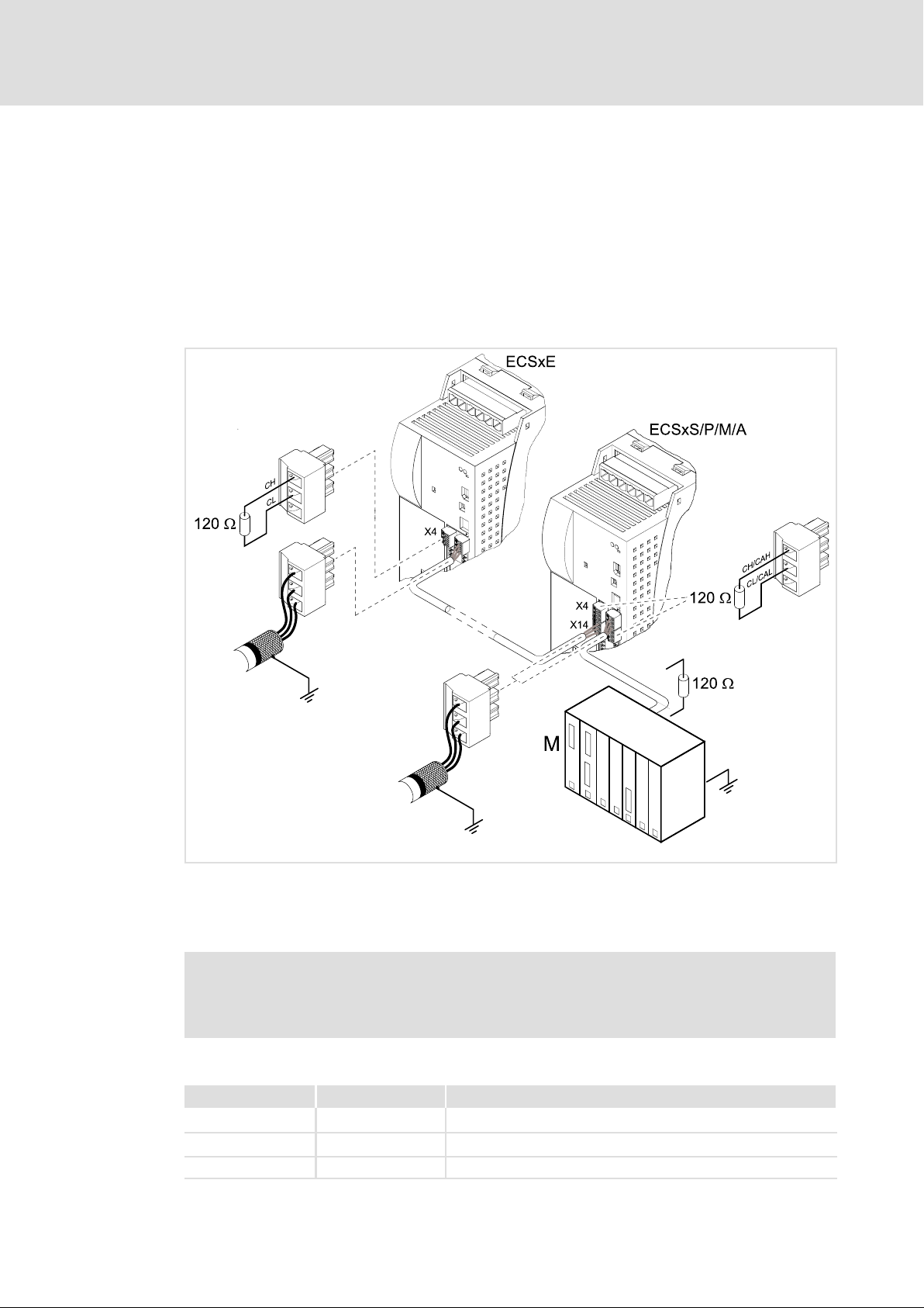
5.6 Connection of system bus (CAN)
The power supply module has a system bus interface (X4) for the communication. This
interface serves to
ƒ connect the axis modules of the ECS series.
ƒ set parameters and display code contents.
System bus(CAN) wiring
Electrical installation
Connection of system bus (CAN)
5
Fig. 5−9 Example of wiring the system bus (CAN)
ECSxE Power supply module
ECSxS/P/M/A Axis module
M Master control, e.g. ETC
Note!
Connect one bus terminating resistor (120 W) each to the first and last node of
the system bus (CAN).
Assignment of the plug connectors
ECSxE092
EDBCSXE040 EN 6.0
X4 (CAN) X14 (CAN−AUX) Description
CH CAH CAN−HIGH
CL CAL CAN−LOW
CG CAG Reference potential
53
Page 54

5
Electrical installation
Connection of system bus (CAN)
Specification of the transmission cable
We recommend the use of CAN cables according to ISO 11898−2:
CAN cable according to ISO 11898−2
Cable type Twisted pair with shielding
Impedance 120 W (95 ... 140 W)
Cable resistance
Cable length £ 300 m £ 70 mW/m
Cable length £ 1000 m £ 40 mW/m
Signal propagation delay £ 5 ns/m
Bus cable length
Note!
The permissible cable lengths must be observed.
1. Check the compliance with the total cable length in Tab. 5−1.
The baud rate determines the total cable length.
CAN baud rate [kbit/s] Max. bus length [m]
50 1500
125 630
250 290
500 120
1000 25
Tab. 5−1 Total cable length
2. Check the compliance with the segment cable length in Tab. 5−2.
The segment cable length is determined by the cable cross−section used and the number
of nodes. Without a repeater, the segment cable length corresponds to the total cable
length.
Number of nodes
2 240 m 430 m 650 m 940 m
5 230 m 420 m 640 m 920 m
10 230 m 410 m 620 m 900 m
20 210 m 390 m 580 m 850 m
32 200 m 360 m 550 m 800 m
63 170 m 310 m 470 m 690 m
Tab. 5−2 Segment cable length
Cable cross−section
0.25 mm
2
0.5 mm
2
0.75 mm
2
1.0 mm
2
54
3. Compare the two values detected.
If the value detected from Tab. 5−2 is smaller than the total cable length to be provided
from Tab. 5−1 , repeaters must be used. Repeaters divide the total cable length into
segments.
Observe...
the information on the use of a repeater in the CAN Communication Manual.
EDBCSXE040 EN 6.0
Page 55

6 Commissioning
Check before switching on the power supply module for the first time:
ƒ The wiring for completeness, short−circuit, and earth fault
ƒ The power connection:
– Mains connection via terminals L1, L2, L3 (X21)
– Connection of the RFI filter / mains choke
– Connection of the brake resistor (internal/external) via terminals BR0, BR1 (X22)
– Polarity of the DC bus voltage supply via terminals +UG, −UG (X22)
ƒ The control connection (X6):
– Connection of the 24 V supply, GND
– Connection of temperature sensor contact of the external brake resistor or
connection of jumper when using the internal brake resistor to terminals T1, T2.
– Adjustment of wiring to the signal assignment of the control terminals.
Commissioning 6
ƒ The communication via the system bus (CAN)
EDBCSXE040 EN 6.0
55
Page 56

6
d
Commissioning
Commissioning steps (overview)
6.1 Commissioning steps (overview)
Start
Make basic
settings
( 57)
Operation via system bus (CAN) with
higher−level master
( 59)
Configure system bus (CAN)
Digital inputs
Set X6/DI1, DI2 = HIGH
Specify control wor
l Save parameters in the power supply
module with C0003 = 1.
l Save parameter set with GDC in the
parameter set file.
Control via digital inputs
( 60)
Digital inputs
Set X6/DI1, DI2 = HIGH
Configure monitoring
functions
( 109)
56
Switch on the mains
End
EDBCSXE040 EN 6.0
Page 57

Commissioning
Commissioning steps (overview)
Basic settings with GDC
6
6.1.1 Basic settings with GDC
Note!
Follow the commissioning steps in the given order!
Setting Brief description Detailed
Preconditions l Mains is switched off. (Green LED is dark, red LED is
1. Switch on low−voltage supply.
2. XT keypad or
Connect PC/laptop (with
installed GDC parameter
setting program) to the
power supply module.
3. Set mains voltage. Setting via C0173
4. Set function of the brake
resistor.
5. Only for operation with
external brake resistor:
Deactivate monitoring of the
internal brake resistor.
6. Configure power supply
enable input.
7. Connect mains voltage. The detection of the mains voltage takes about 1 second. If
8. Select operating mode.
information
blinking)
l Power supply module is inhibited.
– Control bit 1 (STE_RESET) = 0
– Power supply enable input X6/DI1 = LOW
l For operation in an EtherCAT network:
– Plug EtherCAT communication module (EMF2192IB)
onto AIF interface (X1).
Parameter setting with XT keypad
l Plug the XT keypad into the AIF interface (X1).
l Not possible for operation in an EtherCAT network, since
the AIF interface (X1) is already assigned by the EtherCAT
module (see "Preconditions" above).
Parameter setting with GDC
l Connect PC/laptop to system bus interface (X4) with PC
system bus adapter EMF2173IB/EMF2177IB.
l Start GDC and select the device to be set.
l Setting of the connected ECS axis modules:
– C0173: Set DC bus thresholds according to the mains
voltage used.
– Set C0175 = 3 (charging current limitation is not active)
Setting via C0127
(Brake chopper and/or fast discharge function (short−circuit
braking))
C0579 = 3 (internal brake resistor deactivated) 66
l DC bus is charged if X6/DI1 = HIGH
l Set the response of the power supply module for
X6/DI1 = LOW via C0468.
the mains voltage is within the operating range ( 113)
l the green LED at the power supply module will be
blinking.
l XT keypad displays "ok".
C0001 = 0 Operation via system bus (CAN) with
higher−level master
C0001 = 1 Control via digital inputs 60
72
70
62
63
64
59
EDBCSXE040 EN 6.0
C0001 = 2 Operation via EtherCAT
l plugged−on EtherCAT module (EMF2192IB)
with higher−level master
61
57
Page 58

6
Commissioning
Commissioning steps (overview)
Basic settings with GDC
The basic settings are now complete: Please continue with the settings for the operating
mode selected:
ƒ Operation via system bus (CAN) with higher−level master: 59
ƒ Control via digital inputs: 60
ƒ Operation via EtherCAT with higher−level master: 61
58
EDBCSXE040 EN 6.0
Page 59

Commissioning
Commissioning steps (overview)
Operation via system bus (CAN)
6
6.1.2 Operation via system bus (CAN) with higher−level master
Note!
Follow the commissioning steps in the given order!
Setting Short description Detailed
Conditions l Basic settings completed.
l C0001 = 0
1. Set baud rate. l Setting via DIP switch (S1) or C0351
l Lenze setting: 500 kbits/s
l Changes are accepted after
– a "Reset Node" (e.g. C0358 = 1, 104).
– switching off and on again the low−voltage
supply.
2. Set CAN node address at the power
supply module and at each axis
module.
3.
Set identifier for process data
communication.
The master sets the system bus (CAN) to the "Operational" status.
4. If necessary, adapt further codes to
your application.
5. Set input X6/DI2 to HIGH. If the power supply module is ready for operation,
6. Set input X6/DI1 to HIGH. Charging is enabled.
7. Specify control word. l Reset bit must be set to "0" in the first
8. Transmit sync telegram (optional). Sync telegram will only be received by the power
9. Specify control word. l Reset bit (LOW active) must be set to "1" to
10. Transmit sync telegram (optional). See 8.
Each address can be used only once in the
network!
l Setting via DIP switch (S1) or C0350
l Lenze setting power supply module: 32
l Changes are accepted after
– a "Reset Node" (e.g. C0358 = 1, 104).
– switching off and on again the low−voltage
supply.
Setting via
l C0353
l C0354
l Master/slave operation: C0352
l Mode for the process data transfer:
– C0360 = 1: cyclic (sync−controlled), 87)
– C0360 = 0: event−controlled/cyclic without
sync ( 85)
l Boot up time/cycle time for process data
transfer: C0356
l "Node Guarding": C0352, C0382, C0383,
C0384
output X6/DO1 is set to HIGH.
telegram.
l Transmit control word via CAN word 0.
l Initialise toggle bit or deactivate monitoring.
supply module if C0360 = 1 ( 101).
switch on the power supply module.
l Set controller enable bit to "1" if output
X6/DO1 is to be set to HIGH when ready for
operation.
information
57
95
95
98
100
101
101
102
105
118
105
EDBCSXE040 EN 6.0
After some seconds the earth−fault test is complete and the DC bus is charged. The power
supply module is now ready for operation (status word 1, bit 0 = 1).
59
Page 60

6
Commissioning
Commissioning steps (overview)
Control via digital inputs
6.1.3 Control via digital inputs
Note!
Follow the commissioning steps in the given order!
Setting Short description Detailed
Initial state:
l Basic settings completed.
l C0001 = 1
1. Set input X6/DI2 to HIGH. Output X6/DO1 is set to HIGH when the module
2. Set input X6/DI1 to HIGH. Charging process is started.
After some seconds the earth−fault test is complete and the DC bus is charged. The power
supply module is now ready for operation (status word 1, bit 0 = 1).
information
57
is ready for operation.
60
EDBCSXE040 EN 6.0
Page 61

Commissioning
Commissioning steps (overview)
Operation via EtherCAT
6
6.1.4 Operation via EtherCAT with higher−level master
Note!
Follow the commissioning steps in the given order!
Setting Brief description Detailed
Conditions l EMF2192IB EtherCAT module is plugged onto
1. Parameterise EtherCAT module. Detailed information can be found in the
2. Switch on CE0 monitoring. (optional) Set C0126 = 0 (TRIP).
3. Set EtherCAT module to "Operational".
4. Set input X6/DI2 to HIGH. If the power supply module is ready for operation,
5. Set input X6/DI1 to HIGH. Charging is enabled.
6. Specifiy control word.
the AIF interface (X1).
l Basic settings completed.
l C0001 = 2
EMF2192IB (EtherCAT) communication manual.
l CE0: Communication error on the automation
interface (AIF)
output X6/DO1 is set to HIGH.
A Reset bit must be set to "0" in the first
telegram.
B Specify control word via AIF.
Note: If AIF control is used it is not required to
operate a toggle bit (not implemented).
C Reset bit (LOW active) must be set to "1" to
switch on the power supply module.
D Set controller enable bit to "1" if output
X6/DO1 is to be set to HIGH when ready for
operation.
information
57
After some seconds the earth−fault test is complete and the DC bus is charged. The power
supply module is now ready for operation (status word 1, bit 0 = 1).
EDBCSXE040 EN 6.0
61
Page 62

6
Commissioning
Setting the mains voltage
6.2 Setting the mains voltage
The correct mains voltage must be set in the power supply module to ensure correct
operation. The Lenze setting is the automatic adaptation of the switching thresholds for
the brake chopper operation using the mains voltage measured (C0173 = 4). Optionally,
also fixed values can be set.
ƒ C0173 can be found in the GDC parameter menu ( 71) under Short setup.
Stop!
Inhibit the power supply module before setting the mains voltage:
ƒ Control bit 1 (STE_RESET) = 0
ƒ Digital input X6/DI1 = LOW
Parameterisation of the connected axis modules:
ƒ Set the DC bus voltage thresholds of the connected axis modules via axis
module code C0173 according to the mains voltage used.
ƒ Parameterise the charge relay function of the connected axis modules with
C0175 = 3.
ƒ Please observe the notes given in the detailed documentation on the axis
modules!
Parameter
C0173
Mains voltage selection
62
Selection list (Lenze setting printed in bold) Information
Designation
Mains voltage selection
No response
0 Operation on 230 V mains
1 Operation on 400 V mains
2 Operation on 460 V mains
3 Operation on 480 V mains
4 Automatic determination
Data type: INTEGER_32
Index: 24402
dec
= 5F52
hex
Switching thresholds for DC bus voltage and brake resistor
Depending on the mains voltage set in C0173, there are the following switching thresholds
for the DC−bus voltage:
Value in
C0173
0 230 380 370
1
2
3 480 765 750
4
Mains voltage
[V]
400 ... 460 735 720
180 ... 260 380 370
261 ... 528 765 750
Brake resistor
On Off
DC−bus voltage [V]
OU error
(overvoltage threshold)
880
62
EDBCSXE040 EN 6.0
Page 63

Setting chopper operation and short−circuit braking
6.3 Setting chopper operation and short−circuit braking
The "short−circuit braking" function serves to rapidly discharge the DC bus via the brake
resistor. For this, the brake chopper IGBT is switched on permanently. The low−voltage
supply of the power supply module must be ensured for this purpose.
Stop!
Pay attention to the kinetic energy of permanent−magnet synchronous motors
during short−circuit braking!
Observe when short−circuit braking is deactivated:
ƒ Rapid discharge of the DC bus via the brake resistor is not possible.
ƒ For rapid discharge of the DC bus parameterise the charge relay function of
the connected ECS axis modules with C0175 = 3.
ƒ For the earth−fault test the DC bus is discharged via the brake resistor after
switching on the low−voltage supply, independently of the settings.
ƒ The discharging time depends on the entire DC bus circuit.
Observe when brake chopper IGBT is switched off:
During operation in generator mode
ƒ overvoltage can occur in the DC bus.
ƒ energy cannot be discharged from the DC bus.
Commissioning
6
ƒ This function is carried out automatically with most error messages ( 67) but it
can also be requested via the master control system or manually.
ƒ As the DC bus must be safely disconnected from the mains for short−circuit braking,
the brake chopper IGBT is switched on with a delay of approx. 150 ms after the
short−circuit braking request.
ƒ The power supply enable input X6/DI1 can be configured in such a way that
short−circuit braking is triggered with a LOW level ( 64).
ƒ The control bit 2 (STE_KSB) can be set by the control system when bus control is
used ( 105).
ƒ In the case of manual operation (C0001 = 1), the STOP key of the keypad XT can also
be configured to short−circuit braking via C0469.
The short−circuit braking function can be activated in the GDC parameter menu ( 71)
under Short setup via C0127.
Parameter
C0127
Activation of brake chopper IGBT/fast discharge function (short−circuit braking)
63
Selection list (Lenze setting printed in bold) Information
Designation
Function of integrated brake transistor
0 Brake chopper and short−circuit
braking
1 Only brake chopper
2 Only fast discharge function
(short−circuit braking)
4 Without function
Data type: INTEGER_32
Index: 24448
dec
= 5F80
hex
EDBCSXE040 EN 6.0
63
Page 64

6
Commissioning
Configuring power supply enable input
6.4 Configuring power supply enable input
A HIGH level at the power supply enable input X6/DI1 enables the charging of the DC bus.
Even if the control is carried out via the system bus (CAN), the input must be set to HIGH
level to charge the DC bus.
The reaction of the power supply module to a low level or falling edge at X6/DI1 can be set
under C0468.
ƒ C0468 can be found in the GDC parameter menu ( 71) under Digital I/O.
Parameter
C0468
Setting of power supply enable via terminal X6/DI1
Note: The parameters can only be changed if the controller is inhibited.
64
Selection list (Lenze setting printed in bold) Information
Designation
Function of power supply enable (X6/DI1)
0 Mains disconnection (slow
discharge)
1 Mains disconnection and
TRIP−RESET
2 Mains disconnection and quick
discharge (short−circuit braking)
4 Mains disconnection, quick
discharge (short−circuit braking),
and TRIP−RESET
Note!
Mains voltage dips can be reduced by decreasing the max. charging current
limit (C0022).
ƒ C0022 can be found in the GDC parameter menu ( 71) under Short setup.
Parameter
C0022
Setting of the maximum charging current after power supply enable
Setting range (min. value | unit | max. value) Lenze setting
2.0 A 25.0
Designation
Max. charging current after power supply enable
16.0 A
ECSxE040: 32.0
(from firmware V4.0)
Data type: INTEGER_32
Index: 24107
Data type: INTEGER_32
Index: 24553
dec
dec
= 5E2B
= 5FE9
hex
hex
64
EDBCSXE040 EN 6.0
Page 65

Commissioning
Configuring power supply enable input
STOP key of the keypad XT
The STOP key only functions if controlled via digital inputs (C0001 = 1).
ƒ The function of the STOP key can be set in the GDC parameter menu ( 71) under
Keypad configuration via C0469.
Stop!
Do not change the function of the STOP key if the STOP function has
previously been activated by pressing the STOP key. The device cannot be
restarted in this case.
6
Parameter
C0469
Setting of the "STOP" keypad key function of the ECSxE power supply module
Note: The parameters can only be changed if the controller is inhibited.
Selection list (Lenze setting printed in bold) Information
Designation
Function of "STOP" keypad key for ECSxE
0 No function
1 Mains disconnection (slow
discharge)
2 Quick discharge (short−circuit
braking)
Data type: INTEGER_32
Index: 24106
dec
= 5E2A
hex
EDBCSXE040 EN 6.0
65
Page 66

6
Commissioning
Operation with external brake resistor
6.5 Operation with external brake resistor
When an external brake resistor is used, monitoring of the internal brake resistor (OC6)
must be deactivated with C0579 = 3.
ƒ C0579 can be found in the GDC parameter menu ( 71) under Short setup and
Monitoring.
Stop!
The device can be destroyed if the monitoring is deactivated while the internal
brake resistor is used.
Parameter
C0579
Monitoring response of the internal brake resistor (fault message OC6)
116
Selection list (Lenze setting printed in bold) Information
Designation
Response − monitoring of internal brake resistor (OC6)
0 TRIP
3 No response
Data type: INTEGER_32
Index: 23996
= 5DBC
dec
hex
66
EDBCSXE040 EN 6.0
Page 67

6.6 After mains switch−on
6.6.1 Detection of the mains parameters
The mains voltage detection will be enabled when the low−voltage supply is switched on.
The following data are continuously recorded:
ƒ Mains voltage amplitude
ƒ Mains phase sequence
ƒ Mains frequency
ƒ Balance of the mains
6.6.2 Monitoring functions
Various monitoring functions ( 109) protect the drive system against impermissible
operating conditions.
Commissioning
After mains switch−on
Detection of the mains parameters
6
If a monitoring function responds,
ƒ the set fault response is triggered to protect the drive and
ƒ the fault message is entered at position 1 in the fault history buffer (C4168/x)
( 130).
In the fault history buffer (C0168/x), fault messages are saved in codes as 4−digit numbers.
The first digit describes the type of fault response. The last three digits correspond to the
fault number.
No. of the fault message Type of response
0xxx TRIP
1xxx Message
2xxx Warning
3xxx FAIL−QSP (only for ECSxS/P/M/A axis modules)
Example: C0168/1 = 2061
ƒ x061:
The current fault (subcode 1 of C0168) is a communication error (fault message
"CE0"/no. "x061") between the AIF module and the ECS axis module.
ƒ 2xxx:
The fault response is a warning.
EDBCSXE040 EN 6.0
67
Page 68

6
Commissioning
After mains switch−on
Fault responses
6.6.3 Fault responses
Reaction ð Consequence
TRIP / Short−circuit
braking TRIP
TRIP active: ð The charging of the DC bus is stopped. With short−circuit braking
TRIP is reset: ð The power supply module is ready for operation again.
Message
Message active: ð The charging of the DC bus is stopped.
Message is reset: ð The power supply module is ready for operation again.
Warning
Off STOP!
TRIP the DC bus is quickly discharged via the brake resistor.
ð The drive is coasting (no control).
ð The system bus (CAN) indicates to the master that the power
supply module is not ready for operation.
ð The charging of the DC bus is continued.
Danger!
The drive restarts automatically if the message is removed.
ð The drive is coasting (no control).
ð The system bus (CAN) indicates to the master that the power
supply module is not ready for operation.
ð The charging of the DC bus is continued.
ð The failure is only displayed, the drive continues to run normally.
The drive can be destroyed due to deactivated monitoring
functions.
ð There is no response to the failure.
Display
Keypad XT
RDY IMP Fail
n n
o
o n n
n o n
˘ ˘ ˘
o = off n = on
68
EDBCSXE040 EN 6.0
Page 69

7 Parameter setting
7.1 General information
ƒ Controllers and power supply modules can be adapted to your application by setting
the parameters. A detailed description of the functions can be found in the chapter
"Commissioning" ( 55).
ƒ The parameters for the functions are stored in numbered codes:
– The codes are marked in the text with a "C".
– The code list in the appendix ( 134) provides a quick overview of all codes. The
codes are sorted in numerical ascending order, thus serving as a "reference book".
Parameter setting with XT keypad or PC/laptop
Detailed information on parameter setting with the XT keypad can be found in the
following chapters.
Parameter setting
General information
7
Detailed information ...
on the parameterisation by means of a PC/laptop can be found in the
documentation for the "Global Drive Control" (GDC) parameterisation and
operating program.
In addition to parameter setting, the XT keypad or PC/laptop serves to:
ƒ Control the controller (e. g. inhibiting or enabling)
ƒ Select the setpoints
ƒ Display operating data
ƒ Transfer parameter sets to other controllers (only with PC/laptop).
Parameter setting with a bus system
Detailed information ...
on the parameterisation with a bus system can be found in the
documentation of the communication module to be applied ( 156).
EDBCSXE040 EN 6.0
69
Page 70
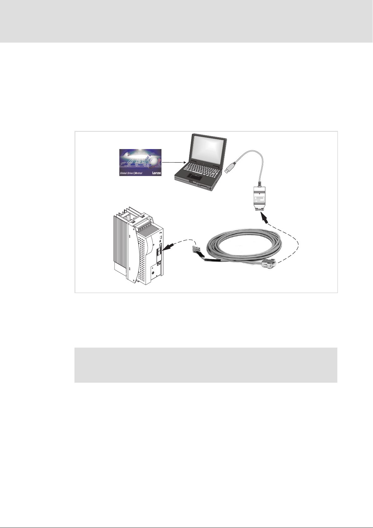
7
7.2 Parameter setting with "Global Drive Control" (GDC)
Parameter setting
Parameter setting with "Global Drive Control" (GDC)
With the "Global Drive Control" (GDC) parameterisation and operating program, Lenze
provides a plain, concise and compatible tool for the configuration of your
application−specific drive task with the PC or laptop:
ƒ The GDC input assistant offers a comfortable motor selection.
ƒ The menu structure supports the commissioning process by its clear structuring.
Fig. 7−1 Using the GDC
Lenze parameter setting program "Global Drive Control" (GDC)
PC or laptop
PC system bus adapter (EMF2173IB/EMF2177IB) with connection cable
Sub−D plug with 3−pole cable
3−pole plug (CAG ˘ CAL ˘ CAH) from connector set ECSZE000X0B
Power supply module ECSxE
0
5
X4
1
4
2
L
3
ECSXE453
70
More detailed information ...
is given in the documentation on the parameter setting and operating
program Global Drive Control (GDC).
EDBCSXE040 EN 6.0
Page 71
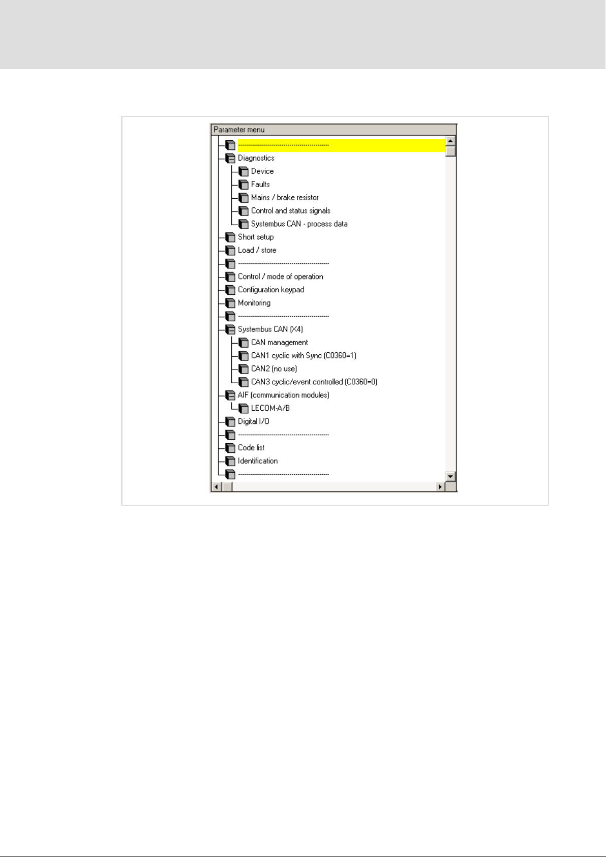
GDC parameter menu
Parameter setting
Parameter setting with "Global Drive Control" (GDC)
7
ECSXE466
Fig. 7−2 GDC parameter menu in case of ECSxE power supply module
By double−clicking the single menu items of the GDC parameter menu the corresponding
codes for setting and display of parameters are indicated.
EDBCSXE040 EN 6.0
71
Page 72
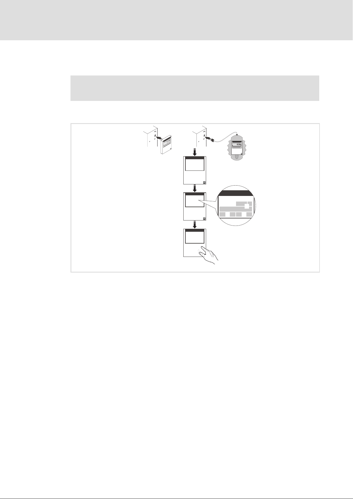
7
dABbc
0
1
2
3
Parameter setting
Parameter setting with the XT EMZ9371BC keypad
Connecting the keypad
7.3 Parameter setting with the XT EMZ9371BC keypad
The keypad is available as accessories.
A complete description is given in the documentation on the keypad.
7.3.1 Connecting the keypad
ABbc
00
50
z
u
n
00
e
M
e
d
o
C
a
r
a
p
P
d
0.00_H
5
SHPRG
V
MCTRL-NOUT
T
U
z
S
YZ
y
EMZ9371BC
dABbc
Menu
p
SHPRG
Code
0050
Para
GLOBAL DRIVE
Init
z
T
YZ
y
S
00
V
U
E82ZWLxxx
dABbc
Menu
p
SHPRG
Code
0050
Para
50.00_Hz
MCTRL-NOUT
z
T
YZ
y
S
E82ZBBXC
00
V
U
d
z
YZ
y
d
z
YZ
y
0050
50.00 Hz
20 %
T
S
0050
50.00 Hz
20 %
T
S
00
V
U
00
V
U
Connect the keypad to the AIF interface (X1) of the axis module/power supply module.
It is possible to connect/disconnect the keypad during operation.
As soon as the keypad is supplied with voltage, it carries out a short self−test.
The operation level indicates when the keypad is ready for operation:
Current status of the axis module/power supply module
Code number, subcode number, and current value
Active fault message or additional status message
Current value in % of the status display defined under C0004
must be pressed to leave the operation level.
9371BC018
72
EDBCSXE040 EN 6.0
Page 73

Parameter setting with the XT EMZ9371BC keypad
7.3.2 Description of the display elements
Parameter setting
Description of the display elements
7
0
1
2
3
dABbc
Menu
p
SHPRG
Code
0050
Para
50.00_Hz
MCTRL-NOUT
z
YZ
T
00
V
4
5
6
7
8
y
S
U
Fig. 7−3 Keypad front view
Status displays
Display Meaning Explanation
Ready for operation
Pulse inhibit active Power outputs inhibited
Adjusted current limitation is exceeded in
Speed controller 1 within its limitation l Drive is torque−controlled
Active fault
Parameter acceptance
Display Meaning Explanation
Parameter is accepted immediately The device immediately operates with the
SHPRG The parameter must be confirmed with The device operates with the new
SHPRG When the controller is inhibited, the
None Display parameters Cannot be changed.
Active level
Display Meaning Explanation
Menu Active menu level l Selection of main menu and submenus
Code Active code level Selection of codes and subcodes
Para Active parameter level Change of parameters in the codes or
None Active operating level Display of operating parameters
Short text
Display Meaning Explanation
Alphanumerical
motor mode or generator mode
parameter must be confirmed with
Contents of the menus, meaning of the codes
and parameters
Display of C0004 in % and the active fault in
the operating level
l Only active for operation with Lenze
devices of the 9300 series!
new parameter value.
parameter value after being confirmed.
The device operates with the new
parameter value after the controller has
been released again.
l No menu for ECSxE power supply
module
subcodes
9371BC002
EDBCSXE040 EN 6.0
73
Page 74
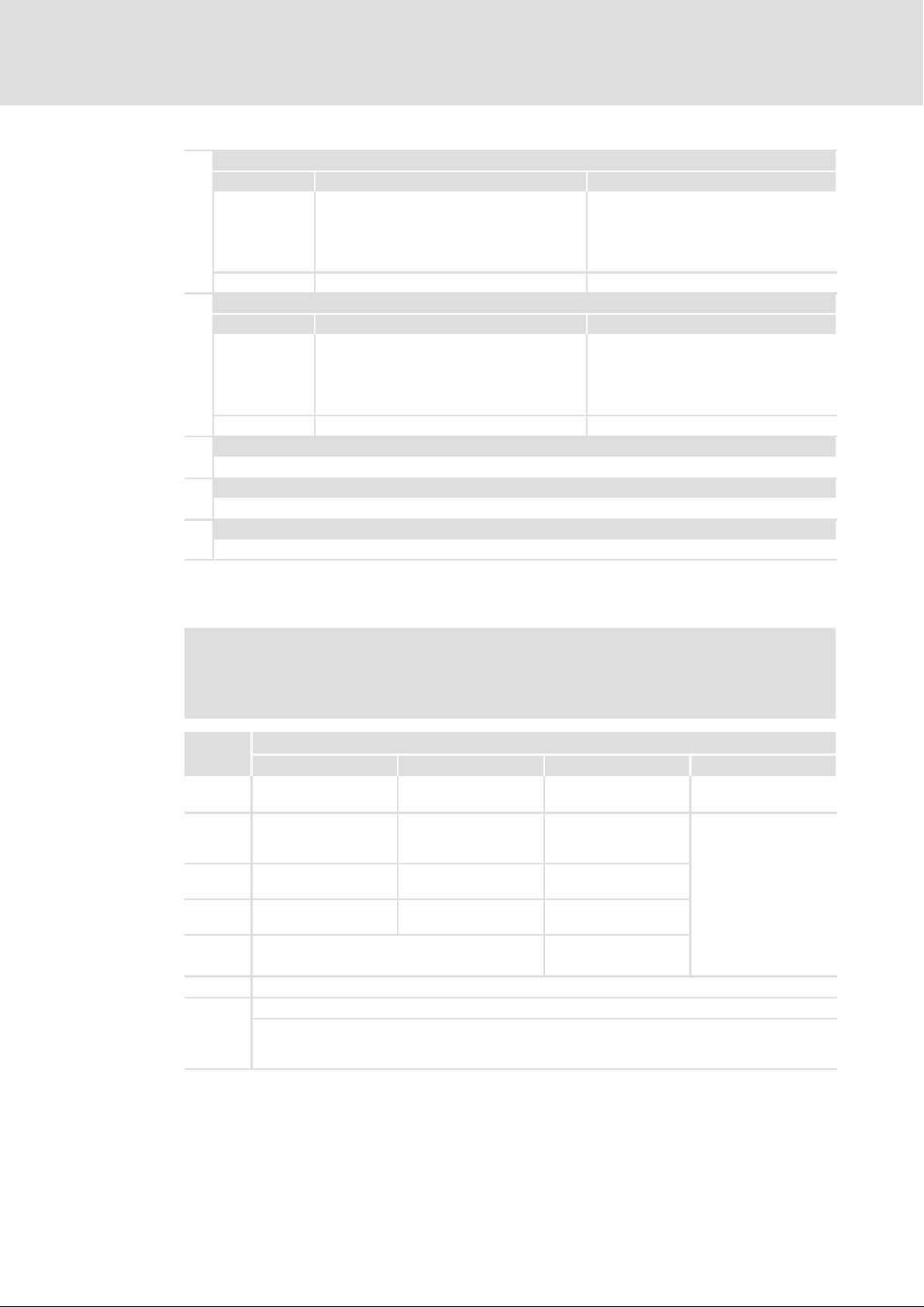
7
Parameter setting
Parameter setting with the XT EMZ9371BC keypad
Description of the function keys
Number
Active level Meaning Explanation
Menu level Menu number l Display is only active when operating
Code level Four−digit code number
Number
Active level Meaning Explanation
Menu level Submenu number l Display is only active when operating
Code level Two−digit subcode number
Parameter value
Parameter value with unit
Cursor
The figure over the cursor can be changed directly in the parameter level.
!
Function keys
For description see the following table.
Lenze devices of the 8200 vector or
8200 motec series.
l No menu for ECSxE power supply
module
Lenze devices of the 8200 vector or
8200 motec series.
l No menu for ECSxE power supply
module
7.3.3 Description of the function keys
Note!
"
#
"
#
$
% Cursor to the left
& Cancel function of ' key, the LED in the key goes out.
'
1)
2)
Key combinations with :
Press and keep it pressed, then press second key in addition.
Key
Menu level
Load predefined
configurations in the
menu "Short setup"
Change between menu
items
Quick change between
menu items
Change between main menu, submenus and
code level
Inhibit the controller, LED in the key lights up.
Reset fault (TRIP reset): 1. Remove cause of malfunction
No menu for ECSxE power supply module
Only active when operating Lenze devices of the 8200 vector or 8200 motec series.
1)
Code level Parameter level Operating level
Change to parameter
level
2)
Change code number
Quick change of code
number
2. Press '
3. Press &
Function
Change to operating
level
Accept parameters
when SHPRG or
SHPRG is displayed
Change figure over
cursor
Quick change of figure
over cursor
Cursor to the right
Change to code level
74
EDBCSXE040 EN 6.0
Page 75

Parameter setting with the XT EMZ9371BC keypad
7.3.4 Changing and saving parameters
All parameters for the axis module/power supply module parameterisation or monitoring
are stored in codes. The codes are numbered and marked with a "C" in the documentation.
Some codes store the parameters in numbered "subcodes" to provide a clear structure for
parameter setting (e.g. C0517 user menu).
Stop!
Your settings have an effect on the current parameters in the main memory.
You must store your settings as a parameter set to prevent that they will get
lost when switching the mains!
Step Keys Action
1. Select menu " # $ % Select the desired menu with arrow keys.
2. Change to code level $ Display of first code in the menu
3. Select code or subcode # "
4. Change to parameter level
5. If SHPRG is displayed, inhibit
controller
6.
Change parameter
A $ % Move cursor under the digit to be changed
B
7.
Accept changed parameter
Display SHPRG or SHPRG Confirm change to accept parameter
Display − The parameter was accepted immediately.
8. If necessary, enable controller & The drive should be running again.
9.
Change to code level
A Display of operating level
B Display of the code with changed parameters
10. Change further parameters Restart the "loop" at step 1. or step 3.
11.
Save changed parameters
A " # $ % Select Code C0003 "PAR SAVE" in the menu
B Change to parameter level
Select parameter set in which the
parameters are to be saved
permanently
12.
Change to code level
C $ Save as parameter set 1:
D When "OK" is displayed, the settings are permanently
A Display of operating level
B Display C0003 "PAR SAVE"
Parameter setting
Changing and saving parameters
Display of the current parameter value
' The drive is coasting.
# " Change digit
#
"
Change digit quickly
Display "OK"
"Load/Store"
Display "0" and "Ready"
ð set "1" "Save PS1"
saved.
7
EDBCSXE040 EN 6.0
75
Page 76

Configuration8
8 Configuration
The drive system can be adapted to your application by configuring the power supply
module. These interfaces can be used to configure the power supply module:
ƒ X1 ˘ AIF (automation interface)
– For the connection of the keypad XT or communication modules ( 156) which
serves to access the codes.
ƒ X4 ˘ System bus interface (CAN)
– PC interface/HMI for parameter setting and diagnostics (e.g. with the Lenze
parameter setting and operating program "Global Drive Control")
or
– Interface to a decentralised I/O system
Systembus (CAN)
dABbc
Menu
p
SHPRG
Code
00
0050
X4
4
0
X1
MCTRL-NOUT
z
YZ
y
Para
50.00_Hz
T
V
S
U
1
X1 X1
X4
X14
5
2
X4
X14
3
X1 X1
X4
X14
Fig. 8−1 Example: Wiring of the MotionBus (CAN) and system bus (CAN)
Keypad XT or another communication module
PC/laptop or HMI
Decentralised I/O system
Higher−level host system / MotionBus control
ECSxE... power supply module
ECSxS/P/M/A... axis module
MotionBus (CAN)
X4
X14
ECSXA028
76
EDBCSXE040 EN 6.0
Page 77
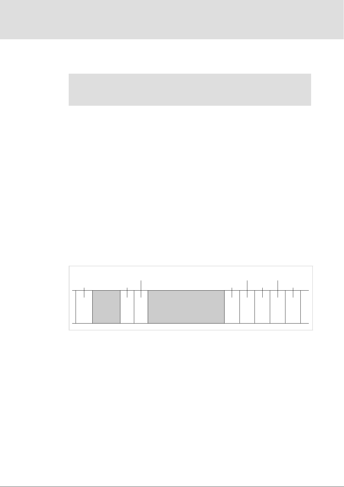
General information about the system bus (CAN)
Structure of the CAN data telegram
8.1 General information about the system bus (CAN)
Note!
The information on this chapter will be part of the "CAN Communication
Manual" at a later date.
All Lenze drive and automation systems are equipped with an integrated system bus
interface for the networking of control components on field level.
Via the system bus interface, for instance process data and parameter values can be
exchanged between the nodes. In addition, the interface enables the connection of further
modules such as distributed terminals, operator and input devices or external controls and
host systems.
The system bus interface transmits CAN objects following the CANopen communication
profile (CiA DS301, version 4.01) developed by the umbrella organisation of CiA (CAN in
Automation) in conformity with the CAL (CAN Application Layer).
Configuration
8
Tip!
For further information visit the homepage of the CAN user organisation CiA
(CAN in Automation): www.can−cia.org.
8.1.1 Structure of the CAN data telegram
Control field CRC delimit. ACK delimit.
Start RTR bit CRC sequence ACK slot End
Identifier User data (0 ... 8 bytes)
l Network management
1 bit 11 bits 1 bit 6 bits 15 bits 1 bit 1 bit 1 bit 7 bits
Fig. 8−2 Basic structure of the CAN telegram
Identifier
The identifier determines the priority of the message. Moreover, the following is coded:
ƒ The CAN node address (device address in the CAN network) of the node which is to
receive the CAN telegram.
See also chapter "Addressing of the parameter and process data objects" ( 94).
l Process data
l Parameter data
EDBCSXE040 EN 6.0
ƒ The type of user data to be transferred
77
Page 78

8
Configuration
General information about the system bus (CAN)
Structure of the CAN data telegram
User data
The user data area of the CAN telegram either contains network management data,
process data or parameter data:
User data Description
Network management data
(NMT data)
Process data
(PDO, Process Data Objects)
Parameter data
(SDO, Service Data Objects)
The information serves to establish communication via the CAN network
l Process data are transmitted via the process data channel.
l The process data serve to control the controller.
l Process data can be accessed directly by the higher−level host system.
The data are, for instance, stored directly in the I/O area of the PLC. It is
necessary that the data can be exchanged between the host system
and the controller within the shortest time possible. In this connection,
small amounts of data can be transferred cyclically.
l Process data are transmitted between the higher−level host system and
the controllers to ensure a permanent exchange of current input and
output data.
l Process data are not stored in the controller.
l Process data are, for instance, setpoints and actual values.
l Parameter data are transferred via the parameter data channel and
acknowledged by the receiver, i.e. the receiver gets a feedback whether
the transmission was successful.
l Parameter data of Lenze devices are called codes.
l The parameter data channel enables access to all Lenze codes and all
CANopen indexes.
l Parameters are set, for instance, for the initial commissioning of a
plant or when material of a production machine is exchanged.
l Usually the transfer of parameters is not time−critical.
l Parameter changes are stored in the controller.
l Parameter data are, for instance, operating parameters, diagnostic
information and motor data.
Tip!
The other signals refer to the transfer features of the CAN telegram that are
not described in these instructions.
For further information visit the homepage of the CAN user organisation CiA
(CAN in Automation): www.can−cia.org.
78
EDBCSXE040 EN 6.0
Page 79

General information about the system bus (CAN)
Communication phases of the CAN network (NMT)
8.1.2 Communication phases of the CAN network (NMT)
With regard to communication the controller knows the following states:
Status Explanation
"Initialisation"
(Initialisation)
"Pre−operational"
(before ready for operation)
"Operational"
(Ready for operation)
"Stopped" Only network management telegrams can be received.
After the controller is switched on, the initialisation process starts. During this
phase the controller is not involved in the data exchange on the bus.
Furthermore, a part of the initialisation or the entire initialisation process can
be executed in each NMT status by transmitting different telegrams (see "state
transitions"). All parameters will be written with their set values.
After the initialisation is completed, the controller is in the "Pre−Operational"
status.
The controller can receive parameter data.
The process data is ignored.
The controller can receive parameter data and process data.
Configuration
8
EDBCSXE040 EN 6.0
79
Page 80
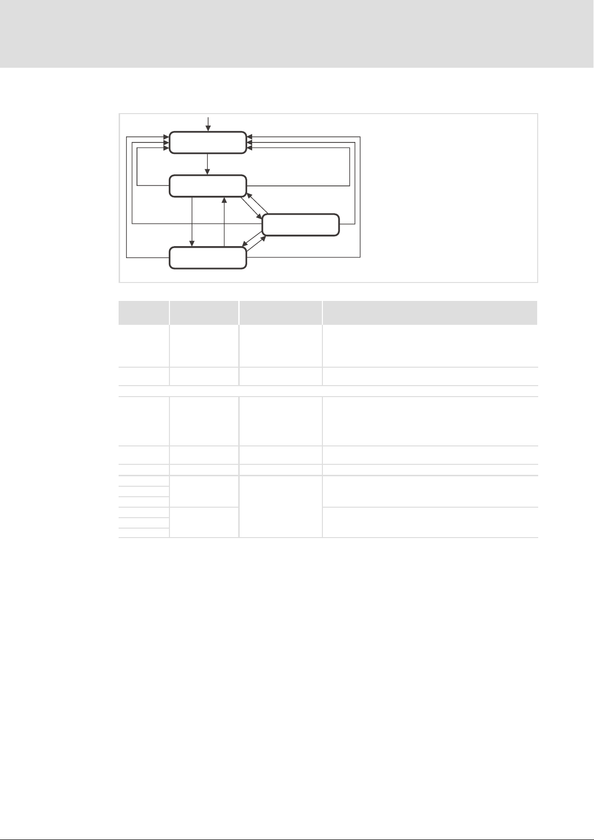
8
Configuration
General information about the system bus (CAN)
Communication phases of the CAN network (NMT)
State transitions
(1)
Initialisation
(2)
(14)
Pre-Operational
(7)
(4)
(13)
(3)
(12)
Operational
(5)
(6)
Stopped
(8)
Fig. 8−3 State transitions in the CAN network (NMT)
(11)
(10)
(9)
E82ZAFU004
State
transition
(1) − Initialisation
(2) − Pre−operational
From here, the states are changed over by the master for the entire network. A target address included in the command specifies the receiver/s.
(3), (6) 01 xx Operational
(4), (7) 80 xx Pre−operational
(5), (8) 02 xx Stopped Only network management telegrams can be received.
(9)
(10)
(11)
(12)
(13)
(14)
Command
xx = 00
(hex)
81 xx
82 xx
hex
Network status after
change
Initialisation
Effect on process or parameter data after state change
When the mains is switched on, the initialisation is started automatically.
During the initialisation the controller is not involved in the data
exchange.
After the initialisation is completed, the node changes automatically to
the "Pre−Operational" status.
In this phase the master decides how the controllers take part in the
communication.
Network management telegrams, sync, emergency, process data (PDO)
and parameter data (SDO) are active (corresponds to "Start Remote
Node")
Optional:
In case of change, event−controlled and time−controlled process data
(PDO) are sent once.
Network management telegrams, sync, emergency, and parameter data
(SDO) are active (corresponds to "Enter Pre−Operational State")
Initialisation of all parameters in the communication module with the
values stored (corresponds to "Reset Node")
Initialisation of communication−relevant parameters (CiA DS 301) in the
communication module with the values stored (corresponds to "Reset
Communication")
With this assignment, all devices connected are addressed by the telegram. The
state can be changed for all devices at the same time.
xx = node ID If a node address is specified, only the state of the addressed device will be
changed.
80
EDBCSXE040 EN 6.0
Page 81
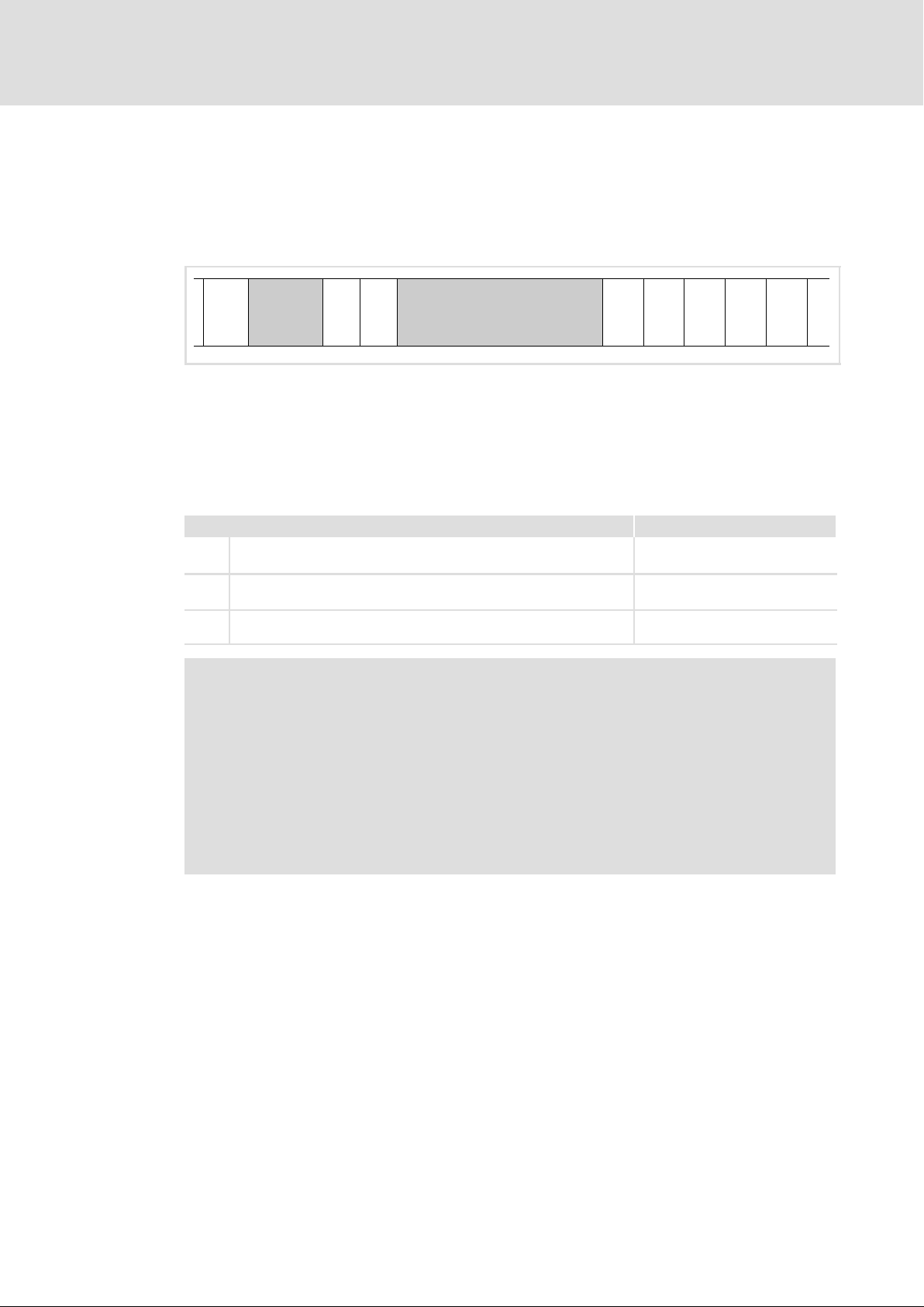
Configuration
General information about the system bus (CAN)
Communication phases of the CAN network (NMT)
Network management (NMT)
The telegram structure used for the network management contains the identifier and the
command included in the user data which consists of the command byte and the node
address.
Identifier User data
8
Value = 0
11 bits
Fig. 8−4 Telegram for switching over the communication phases
Contains commands only
2bytes
The communication phases are changed over by a node, the network master, for the entire
network. The change−over can also be done by a controller.
With a certain delay after mains connection, a telegram is sent once which changes the
status of the entire drive system to "Operational". The delay time can be set via the
following codes:
Interface Code
X1 Automation interface (AIF) C2356/4
X4 ECSxS/P/M: MotionBus (CAN)
ECSxA/E: System bus (CAN)
X14 System bus (CAN)
l Interface is not available for ECSxE.
C0356/4
C2456/4
Note!
Communication via process data only is possible with a state change to
operational"!
Example:
For changing the state of all nodes on the bus from "pre−operational" to
operational" via the CAN master, the following identifier and user data must
be set in the telegram:
ƒ Identifier: 00 (broadcast telegram)
ƒ User data: 0100 (hex)
EDBCSXE040 EN 6.0
81
Page 82
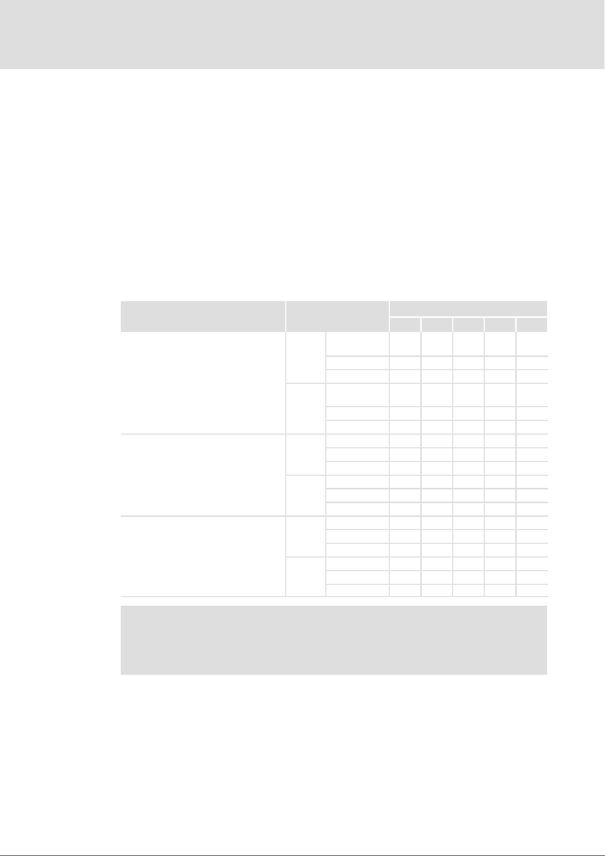
8
Configuration
General information about the system bus (CAN)
Process data transfer
8.1.3 Process data transfer
Definitions
ƒ Process data telegrams between host and drive are distinguished as follows:
– Process data telegrams to the drive
– Process data telegrams from the drive
ƒ The CANopen process data objects are designated as seen from the node’s view:
– RPDOx: process data object received by a node
– TPDOx: process data object sent by a node
8.1.3.1 Available process data objects
The following process data objects (PDOs) are available for the ECS modules via the
interfaces X1, X4 and X14:
Interface PDOs
X1
Automation interface (AIF)
X4
ECSxS/P/M: MotionBus (CAN)
ECSxA/E: System bus (CAN)
X14
System bus (CAN)
Interface is not available for ECSxE.
RPDO: to ECS module
TPDO: from ECS module
AIF1_IN ˘ ü V3.0 or
RPDO
TPDO
RPDO
TPDO
RPDO
TPDO
AIF2_IN ˘ ü ˘ ˘ ü
AIF3_IN ˘ ü ˘ ˘ ü
AIF1_OUT ˘ ü V3.0 or
AIF2_OUT ˘ ü ˘ ˘ ü
AIF3_OUT ˘ ü ˘ ˘ ü
CAN1_IN ü ü ü ü ü
CAN2_IN ˘ ü ü ˘ ü
CAN3_IN ü ü ü ˘ ü
CAN1_OUT ü ü ü ü ü
CAN2_OUT ˘ ü ü ˘ ü
CAN3_OUT ü ü ü ˘ ü
CANaux1_IN ˘ ˘ ü ˘ ü
CANaux2_IN ˘ ˘ ü ˘ ü
CANaux3_IN ˘ ˘ ˘ ˘ ü
CANaux1_OUT ˘ ˘ ü ˘ ü
CANaux2_OUT ˘ ˘ ü ˘ ü
CANaux3_OUT ˘ ˘ ˘ ˘ ü
Availability in ECS modules
ECSxE ECSxS ECSxP ECSxM ECSxA
higher
higher
V3.0 or
higher
V3.0 or
higher
ü
ü
82
Note!
In case of the ECSxE power supply module, the PDOs CAN1_IN/OUT and
CAN3_IN/OUT cannot be used simultaneously. The PDOs to be used are
selected via C0360.
EDBCSXE040 EN 6.0
Page 83
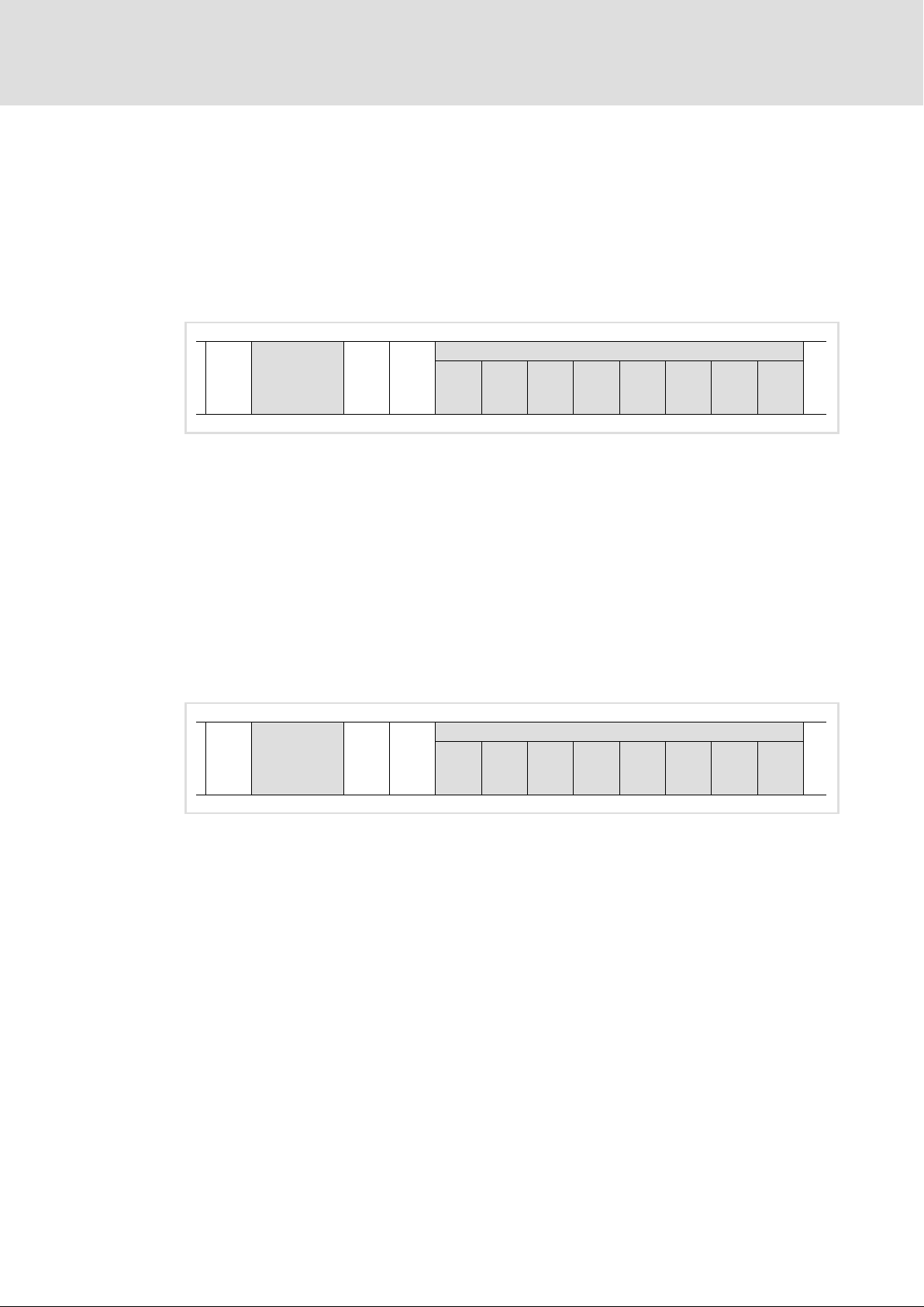
General information about the system bus (CAN)
8.1.3.2 Structure of the process data
The process data telegrams have a maximum user data length of eight bytes each.
Process data input telegram (RPDO)
ƒ The process data input telegram transmits control information to the controller.
ƒ The eight bytes of user data can be freely assigned.
Identifier User data (8 bytes)
11 bits
Fig. 8−5 Structure of process data input telegram (RPDO)
Process data output telegram (TPDO)
Configuration
Process data transfer
00
hex00hex00hex00hex00hex00hex00hex00hex
8
ƒ The process data output telegram reports status information from the controller.
Status information can be as follows:
– Current status of the controller
– Status of the digital inputs
– States about internal analog values
– Fault/error messages
This information enables the higher−level control to respond accordingly.
ƒ The eight bytes of user data can be freely assigned.
Identifier User data (8 bytes)
00
11 bits
Fig. 8−6 Structure of process data output telegram (TPDO)
hex00hex00hex00hex00hex00hex00hex00hex
EDBCSXE040 EN 6.0
83
Page 84
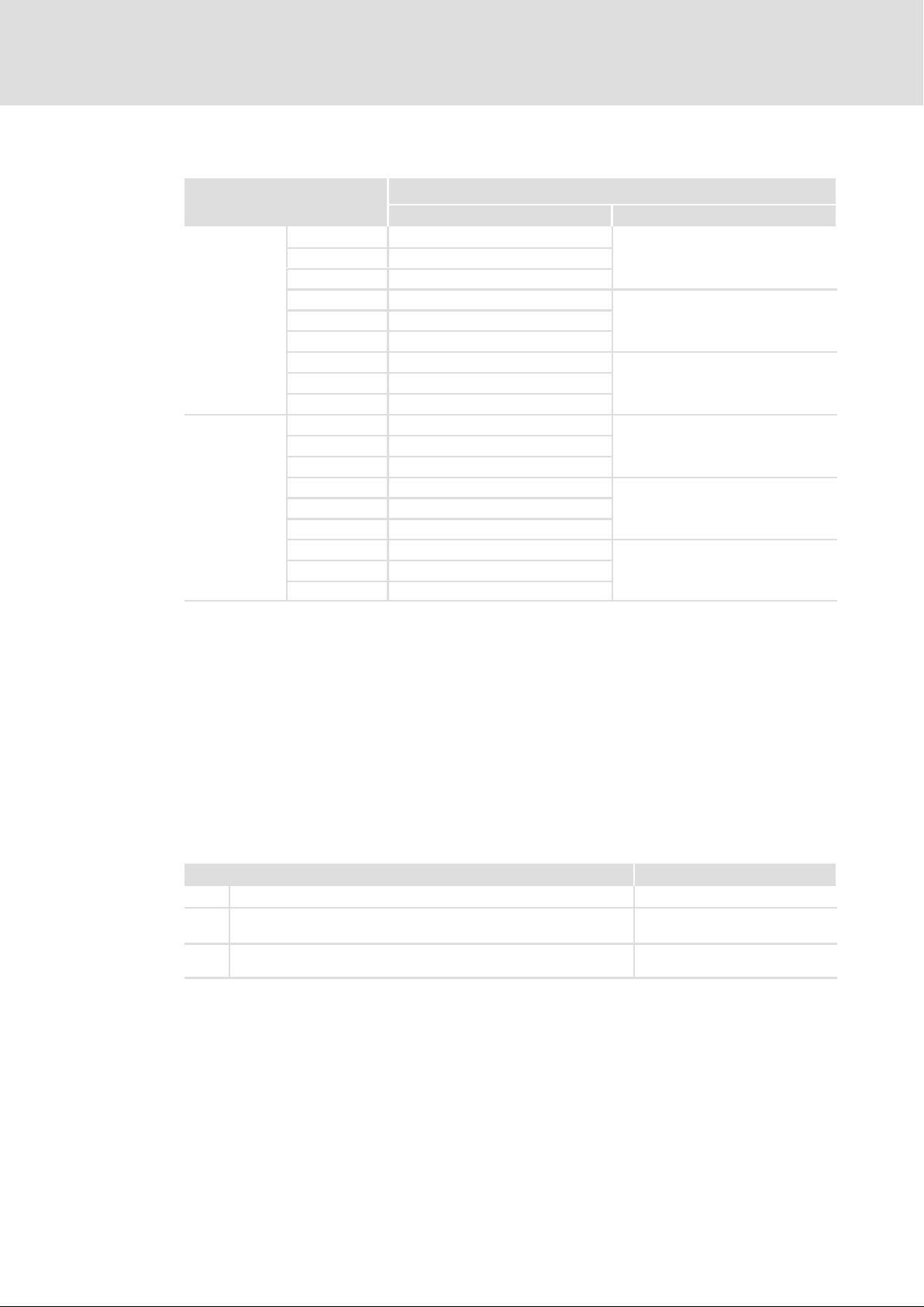
8
Configuration
General information about the system bus (CAN)
Process data transfer
8.1.3.3 Transfer of the process data objects
Process data objects
AIF1_IN
CAN1_IN
CANaux1_IN
AIF2_IN
RPDOs
(to ECS module)
TPDOs
(from ECS module)
ƒ Cyclic data transmission with sync telegram ( 86)
CAN2_IN
CANaux2_IN
AIF3_IN
CAN3_IN
CANaux3_IN
AIF1_OUT
CAN1_OUT
CANaux1_OUT
AIF2_OUT
CAN2_OUT
CANaux2_OUT
AIF3_OUT
CAN3_OUT
CANaux3_OUT
Data transmission
ECSxE ECSxS/P/M/A
˘
cyclic (sync−controlled)
˘
˘
˘
˘
˘
event−controlled/cyclic without sync
˘
˘
cyclic (sync−controlled)
˘
˘
˘
˘
˘
event−controlled/cyclic without sync
˘
cyclic (sync−controlled)
event−controlled/cyclic without sync
event−controlled/cyclic without sync
cyclic (sync−controlled)
event−controlled/cyclic without sync
event−controlled/cyclic without sync
(via AIF1, CAN1, CANaux1)
The sync telegram enables the controller to accept the process data from the master
(RPDOs) or send them to the master (TPDOs).
ƒ Event−controlled data transmission
(via AIF2/3, CAN2/3, CANaux2/3)
The data will be transmitted if a value changes in the corresponding output object.
ƒ Cyclic data transmission without sync telegram
(via AIF2/3, CAN2/3, CANaux2/3)
The data is transmitted in fixed times. The cycle time can be set via the following codes:
Interface Code
X1 Automation interface (AIF) C2356
X4 ECSxS/P/M: MotionBus (CAN)
ECSxA/E: System bus (CAN)
X14 System bus (CAN)
l Interface is not available for ECSxE.
C0356
C2456
– Setting of cycle time > 0: data transmission with fixed cycle time
– Setting of cycle time = 0: event−controlled data transmission
84
EDBCSXE040 EN 6.0
Page 85
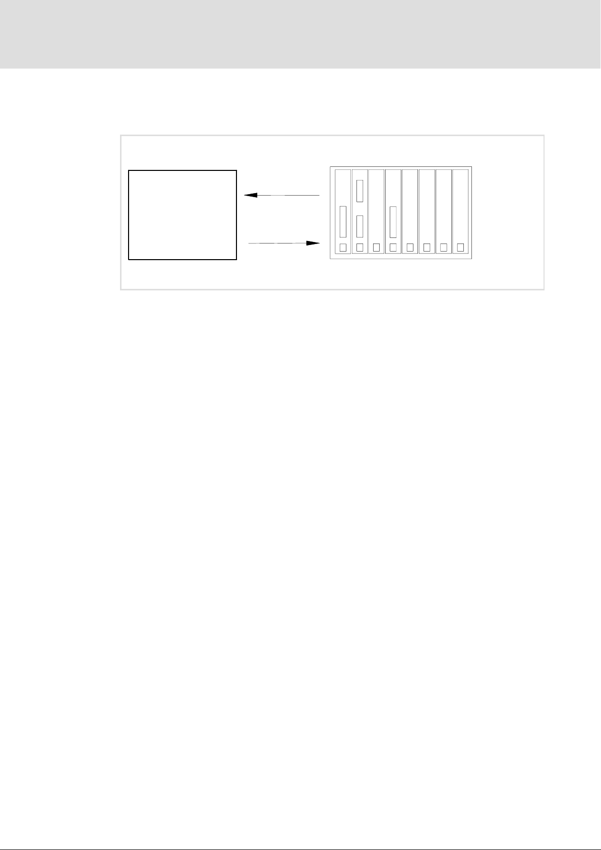
8.1.3.4 Cyclic process data objects
Cyclic process data objects are determined for a higher−level host system.
ECS module
Fig. 8−7 Example: Process data transfer via CAN1_IN and CAN1_OUT
For a quick exchange of process data from or to the master, one process data object is
available for input signals (RPDO1) and one process data object for output signals (TPDO1)
with eight bytes of user data each.
Configuration
General information about the system bus (CAN)
Process data transfer
PDO1, cyclic process data
(setpoints and actual values)
RPDO1: CAN1_IN
TPDO1: CAN1_OUT
Host system
8
EDBCSXE040 EN 6.0
85
Page 86
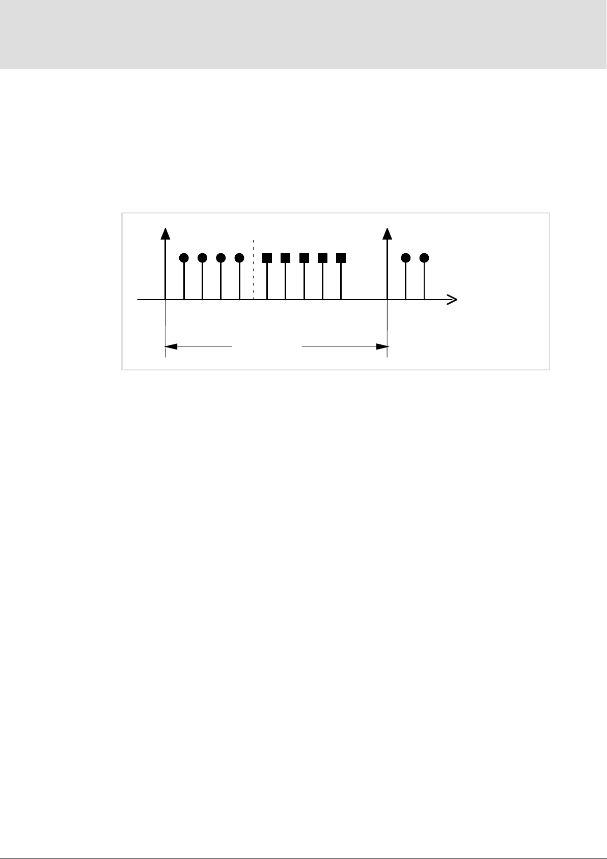
8
Configuration
General information about the system bus (CAN)
Process data transfer
Synchronisation of PDOs with sync−controlled transmission
In order that the cyclic process data can be read by the controller or the controller accepts
the process data, a special telegram, the CAN sync telegram, is used in addition.
The CAN sync telegram is the trigger point for sending process data of the controller to the
master and transferring process data from the master to the controller.
A sync−controlled process data processing requires a corresponding generation of the CAN
sync telegram.
CAN sync telegram
TPDOs RPDOs
1.
Cycle time
Fig. 8−8 Sync telegram
1. After the CAN sync telegram has been received, the synchronous process data from
the controllers are sent to the master (TPDOs). They are read as process input data in
the master.
2. When the transmission process is completed, the process output data (of the
master) are received by the controllers (RPDOs).
All other telegrams (e.g. parameters or event−controlled process data) are accepted
acyclically by the controllers after transmission is completed. The acyclic data are not
displayed in the above illustration. They must be considered when the cycle time is
dimensioned.
2.
CAN sync telegram
3.
86
3. The data in the controller is accepted with the next CAN sync telegram.
Tip!
The response to a CAN sync telegram is determined by the transmission type
selected.
EDBCSXE040 EN 6.0
Page 87
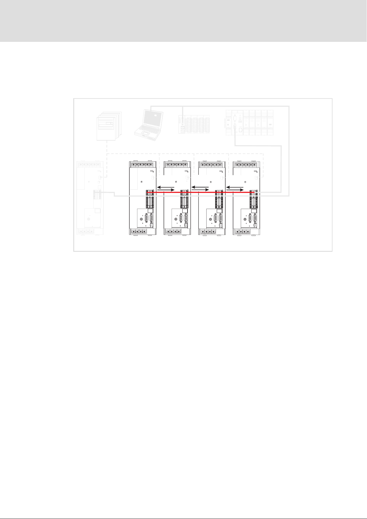
General information about the system bus (CAN)
X4
4
5
Y Z
y
z
T
V
S
U
d ABbc
p
SHPRG
Para
Code
Menu
0050
00
50.00_Hz
MCTRL-NOUT
0
1
3
X1
2
8.1.3.5 Event−controlled process data objects
The event−controlled process data objects are particularly suitable for the data exchange
between controllers and for distributed terminal extensions. They can, however, also be
used by a host system.
0050
50.00_Hz
Configuration
Process data transfer
Systembus (CAN)
MotionBus (CAN)
8
X4
X14
TPDO2
RPDO2
X14
X4
TPDO2
RPDO2
X14
TPDO2
RPDO2
X4 X4
X14
ECSXA219
Fig. 8−9 Example: event−controlled process data objects PDO2
The process data objects serve to transmit simple binary signals (e.g. states of digital input
terminals) or complete values in 16 and 32 bits (e.g. analog signals).
EDBCSXE040 EN 6.0
87
Page 88
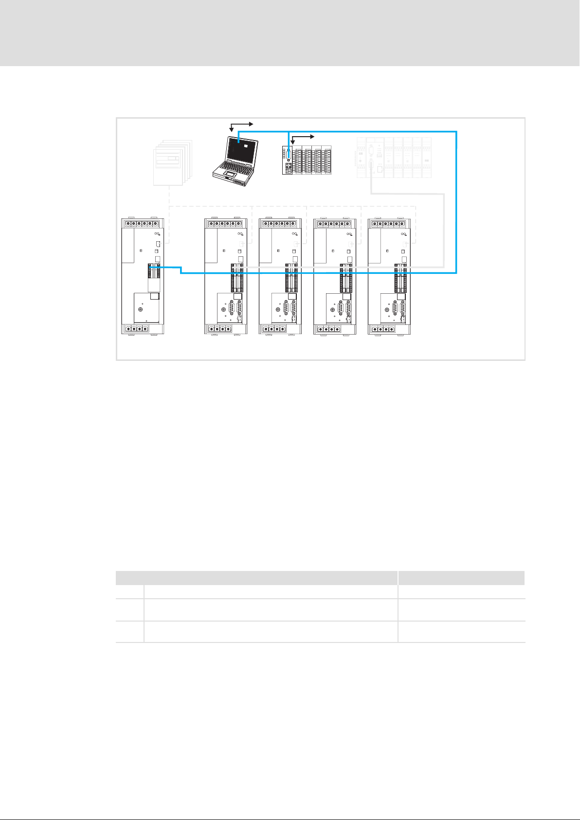
8
5
Y Z
y
z
T
V
S
U
d ABbc
p
SHPRG
Para
Code
Menu
0050
00
50.00_Hz
MCTRL-NOUT
0
3
X1
4
Configuration
General information about the system bus (CAN)
Parameter data transfer
8.1.4 Parameter data transfer
X4
1
X4
X14
SDO1
2
X4
X14
SDO2
X4
X14
Systembus (CAN)
MotionBus (CAN)
X4
X14
Fig. 8−10 Parameter data channels for parameterising ECS
Parameters ...
ƒ are values which are stored under codes in the Lenze controllers.
ECSXA220
ƒ are set e.g. during initial commissioning or while changing materials in a machine.
ƒ are transmitted with low priority.
Parameter data are transmitted as SDOs (Service Data Objects) via the system bus (CAN)
and acknowledged by the receiver. The SDOs enable the writing and reading access to the
object directory.
The CAN bus interfaces X4 and X14 are provided with two separated parameter data
channels each which serve to simultaneously connect different devices for parameter
setting and diagnostics.
The codes for parameter setting and diagnostics of the automation interface (AIF) X1 as
well as the CAN bus interfaces X4 and X14 are divided into separate ranges:
Interface Code range
X1 Automation interface (AIF) C23xx
X4 ECSxS/P/M: MotionBus (CAN)
ECSxA/E: System bus (CAN)
X14 System bus (CAN)
l Interface is not available for ECSxE.
C03xx
C24xx
88
EDBCSXE040 EN 6.0
Page 89
8.1.4.1 User data
Structure of the parameter data telegram
1. byte 2. byte 3. byte 4. byte 5. byte 6. byte 7. byte 8. byte
Command
Note!
Command
The command contains the services for writing and reading the parameters and
information on the length of the user data:
Configuration
General information about the system bus (CAN)
Parameter data transfer
User data (up to 8 bytes)
Data 1 Data 2 Data 3 Data 4
Index
Low byte
Index
High byte
Subindex
The user data is shown in motorola format.
Examples for parameter data transfer can be found from 92.
Low word High word
Low byte High byte Low byte High byte
Display
8
Bit 7
MSB
Command
Write request 0 0 1 0
Write response 0 1 1 0 0 0
Read request 0 1 0 0 0 0
Read response 0 1 0 0 1 1
Error response 1 0 0 0 0 0 0 0
Bit6 Bit5 Bit4 Bit3 Bit 2 Bit 1 Bit 0
Command specifier (cs) toggle (t) Length e E
00 = 4 bytes
01 = 3 bytes
10 = 2 bytes
11 = 1 byte
1 1
LSB
Tip!
Further commands are defined in the CANopen specification DS301,V4.02
(e.g. segmented transfer).
EDBCSXE040 EN 6.0
89
Page 90

8
Configuration
General information about the system bus (CAN)
Parameter data transfer
The command must contain the following information:
Command
Write request
(Transmit parameter to the controller )
Write response
(Acknowledgement, controller
response to write request)
Read request
(Request to read a controller
parameter)
Read response
(Response to read request with
current value)
Error response
(The controller reports a
communication error)
4−byte data
(5. ... 8. byte)
hex dec hex dec hex dec hex dec
23 35 2B 43 2F 47 21 33
60 96 60 96 60 96 60 96
40 64 40 64 40 64 40 64
43 67 4B 75 4F 79 41 65
80 128 80 128 80 128 80 128
2−byte data
(5. and 6. byte)
1−byte data
(5. byte)
Block
"Error response" command: In case of a communication error an "Error response" is
generated by the addressed node. This telegram always contains the value "6" in Data 4
and an error code in Data 3.
The error codes are standardised acc. to DS301, V4.02.
Addressing by index and subindex
The parameter or Lenze code is addressed with these bytes according to the following
formula:
Index = 24575 − (Lenze code number)
Data1...Data4
Parameter value length depending on the data format
Parameter value
(Length: 1 byte)
Parameter value (length: 2 bytes)
Low byte High byte
Low word High word
Low byte High byte Low byte High byte
00
Parameter value (length: 4 bytes)
Note!
Lenze parameters are mainly represented as data type FIX32 (32bit value with
sign, decimally with four decimal positions). To obtain integer values, the
desired parameter value must be multiplied by 10,000
The parameters C0135 and C0150 must be transmitted bit−coded and without
a factor.
00 00
00 00
.
dec
90
EDBCSXE040 EN 6.0
Page 91
Configuration
General information about the system bus (CAN)
Parameter data transfer
Error messages
User data (up to 8 bytes)
1st byte 2nd byte 3rd byte 4th byte 5th byte 6th byte 7th byte 8th byte
Command
ƒ Byte 1:
Index
Low byte
In the command byte the code 128
ƒ Byte 2, 3 and 4:
In these bytes the index (byte 2 and 3) and subindex (byte 4) of the code in which an
error occurred are entered.
ƒ Byte 5 to 8:
In the data bytes 5 to 8 the error code is entered. The structure of the error code is
reversed to the read direction.
Example:
The representation of the error code 06 04 00 41
Index
High byte
Subindex Display
or 80
dec
in the bytes 5 to 8
hex
indicates that a fault has occurred.
hex
Read direction of the error code
8
41 00 04 06
5. byte 6. byte 7. byte 8. byte
Low word High word
Low byte High byte Low byte High byte
Possible error codes:
Command 7th byte 8th byte Meaning
80
80
80
hex
hex
hex
6 6 Wrong index
5 6 Wrong subindex
3 6 Access denied
EDBCSXE040 EN 6.0
91
Page 92

8
Configuration
General information about the system bus (CAN)
Parameter data transfer
8.1.4.2 Examples of the parameter data telegram
Reading parameters
The heatsink temperature C0061 (43 °C) is to be read from the controller with node
address 5 via the parameter data channel 1.
ƒ Identifier calculation
Identifier from SDO1 to controller Calculation
1536 + node address 1536 + 5 = 1541
ƒ Command "Read Request" (request to read a parameter from the controller)
Command Value
Read request 40
ƒ Index calculation:
Index Calculation
24575 − code number 24575 − 61 = 24514 = 5FC2
ƒ Subindex: 0
hex
hex
ƒ Telegram to controller
User data
Command Index
Identifier
1541
ƒ Telegram from controller
Identifier
1413 43
40hex
LOW byte
C2
hex
Command Index
LOW byte
hex
C2
HIGH byte
hex
Index
5F
hex
Index
HIGH byte
5F
hex
Subindex Data 1 Data 2 Data 3 Data 4
00 00 00 00 00
User data
Subindex Data 1 Data 2 Data 3 Data 4
00 B0
– Command:
"Read Response" (response to the read request) = 43
– Identifier:
SDO1 from controller (= 1408) + node address (= 5) = 1413
– Index of the read request:
5FC2
hex
– Subindex:
0
– Data 1 ... 4:
00 06 8F B0 = 430.000 ( 430.000 : 10.000 = 43 °C
hex
hex
8F
hex
06
hex
00
92
EDBCSXE040 EN 6.0
Page 93

Configuration
General information about the system bus (CAN)
Parameter data transfer
Writing parameters
The acceleration time C0012 (parameter set 1) of the controller with the node address 1 is
to be changed to 20 seconds via the SDO1 (parameter data channel 1).
ƒ Identifier calculation
Identifier from SDO1 to controller Calculation
1536 + node address 1536 + 1 = 1537
ƒ Command "Write Request" (transmit parameter to drive)
Command Value
Write request 23
ƒ Index calculation:
Index Calculation
24575 − code number 24575 − 12 = 24563 = 5FF3
ƒ Subindex: 0
ƒ Calculation of the acceleration time
hex
hex
8
Data 1 ... 4 Calculation
Value for acceleration time 20 s ú 10.000 = 200.000
ƒ Telegram to controller
User data
Command Index
hex
LOW byte
F3
hex
LOW byte
F3
hex
Identifier
1537
ƒ Telegram from controller if executed faultlessly
Identifier
1409 60
23hex
Command Index
Index
HIGH byte
5F
hex
Index
HIGH byte
5F
hex
Subindex Data 1 Data 2 Data 3 Data 4
00
User data
Subindex Data 1 Data 2 Data 3 Data 4
00 00 00 00 00
= 00 03 0D 40
40hex
0D
hex
hex
– Command:
"Write Response" (response of the controller (acknowledgement)) = 60
– Identifier:
SDO1 from controller (= 1408) + node address (= 1) = 1409
03
dec
hex
00
hex
EDBCSXE040 EN 6.0
93
Page 94

8
Configuration
General information about the system bus (CAN)
Addressing of the parameter and process data objects
8.1.5 Addressing of the parameter and process data objects
The CAN bus system is based on a message−oriented data exchange between a transmitter
and many receivers. Thus, all nodes can transmit and receive messages at the same time.
The identifier in the CAN telegram ˘ also called COB−ID (Communication Object Identifier)
controls which node is to receive a transmitted message. With the exception of the
network management (NMT) and the sync telegram (Sync) the identifier contains the
node address of the drive besides the basic identifier:
Identifier (COB−ID) = basic identifier + adjustable node address (node ID)
The basic identifier for the ECSxE power supply module is preset ex works with the
following values:
Object
Network management (NMT) 0 0
Sync telegram 128 80
Process data channel to ECSxE in cyclic operation (sync−controlled)
(RPDO: CAN1_IN)
Process data channel from ECSxE in cyclic operation (sync−controlled)
(TPDO: CAN1_OUT)
Process data channel to ECSxE in event−controlled/cyclic operation without sync
(RPDO: CAN3_IN)
Process data channel from ECSxE in event−controlled/cyclic operation without
sync (TPDO: CAN3_OUT)
Parameter data channel 1 to ECSxE (SDO1) 1536 600
Parameter data channel 2 to ECSxE (SDO2) 1600 640
Parameter data channel 1 from ECSxE (SDO1) 1408 580
Parameter data channel 2 from ECSxE (SDO2) 1472 5C0
Node Guarding 1792 700
Basic identifier
dec hex
512 200
384 180
768 300
769 301
Note!
The "8.2.1 Setting of CAN node address and baud rate" chapter contains
information on
ƒ Setting of the node address ( 95).
ƒ Individual addressing ( 98).
94
EDBCSXE040 EN 6.0
Page 95
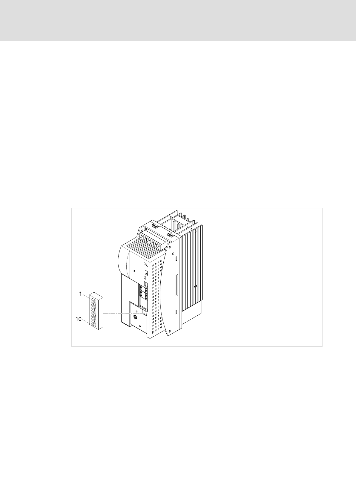
Setting CAN node address and baud rate
8.2 Configuring system bus (CAN)
The codes for configuring the system bus (CAN) can be found in the GDC parameter menu
( 71) under system bus (CAN).
8.2.1 Setting CAN node address and baud rate
The CAN node address and baud rate can be set via the DIP switch (S1) or via C0350/C0351.
ƒ If one of the (address) switches 2 ... 7 of the DIP switch is switched on (ON) and the
low−voltage supply is connected, the setting of the DIP switch is evaluated and
entered into C0350 (CAN node address) and C0351 (baud rate).
ƒ If the (address) switches 2 ... 7 are switched off (OFF), the switch position is not
evaluated. The node address and the baud rate are then taken from C0350 and
C0351.
ƒ The switch 1 of the DIP switch has no function.
Configuration
Configuring system bus (CAN)
8
8.2.1.1 Settings via DIP switch
Fig. 8−11 DIP switch for node address and baud rate (all switches: OFF)
ECSEE_002B
EDBCSXE040 EN 6.0
95
Page 96
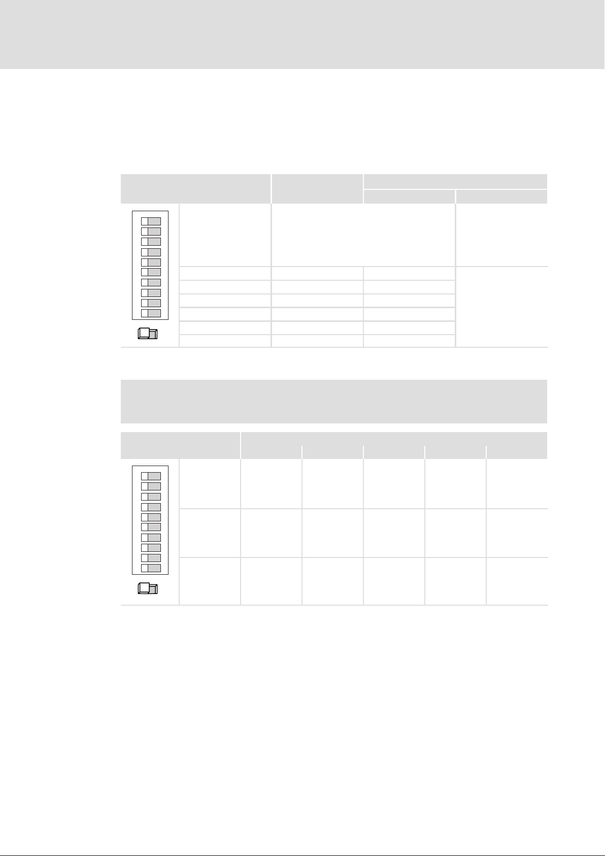
8
Configuration
Configuring system bus (CAN)
Setting CAN node address and baud rate
Node address setting
The node address is set by means of switches 2 ... 7 of the DIP switch. Specific values are
assigned to the switches. The sum of the values specifies the node address to be set (see
example).
Switch Value
ON
1
2
43
5
6
7
8
910
ONOFF
Baud rate setting
Note!
The baud rate must be set identically for all CAN nodes.
Switch
ON
1
2
Example
Switching status Node address
OFF: Node address setting is only valid for CAN
(C0350 is overwritten if one of switches S2 ... S7
S1
is in ON position.)
ON: Node address setting is valid for CAN and
−
CANaux (C0350 and C2450 are overwritten if
one of switches S2 ... S7 is in ON position.)
S2 32 ON
S3 16 ON
S4 8 ON
S5 4 OFF
32 + 16 + 8 = 56
S6 2 OFF
S7 1 OFF
Baud rate [kbit/s]
1000 500 250 125
50
8 ON OFF OFF OFF OFF
43
5
6
7
8
910
9 OFF OFF OFF ON ON
10 OFF OFF ON OFF ON
ONOFF
96
EDBCSXE040 EN 6.0
Page 97

8.2.1.2 Settings via codes
Note!
ƒ If all DIP switches for the node address (S2 ... S7) are in "OFF" position, the
settings under code C0350 (node address) and C0351 (baud rate) apply.
ƒ If only one DIP switch for the node address (S2 ... S7) is in "ON" position, the
settings of DIP switches S2 ... S10 apply.
ƒ The baud rate must be set identically for all CAN nodes.
Configuration
Configuring system bus (CAN)
Setting CAN node address and baud rate
8
Parameter
C0350
Setting of the CAN node address
Note:
l This code is not active if one of the switches 2 ... 7 of the DIP switch is set to "ON". ( 95)
l After the setting, a reset node is required.
l Each CAN node must be assigned a definite node address.
Setting range (min. value | unit | max. value) Lenze setting
1 63 32
Parameter
C0351
Entry of the CAN baud rate
Note:
l The baud rate must be set identically for all CAN nodes.
l This code is not active if one of the switches 2 ... 7 of the DIP switch is set to "ON". ( 95)
l After the setting, a reset node is required.
Selection list (Lenze setting printed in bold) Information
Designation
CAN node address
Designation
CAN baud rate
0 500 kbps
1 250 kbps
2 125 kbps
3 50 kbps
4 1000 kbps
Data type: INTEGER_32
Index: 24225
Data type: INTEGER_32
Index: 24224
dec
dec
= 5EA1
= 5EA0
hex
hex
EDBCSXE040 EN 6.0
Save changes with C0003 = 1.
The settings are only accepted after carrying out one of the following actions:
ƒ Switching on again the low−voltage supply
ƒ Reset node via the bus system (by the network management (NMT))
ƒ Reset node with C0358 = 1 by means of keypad XT ( 104)
– If the reset node is executed via GDC, the communication will be interrupted as a
matter of principle. Thus, it is required to log in again manually or to research the
devices connected to the bus.
97
Page 98

8
Configuration
Configuring system bus (CAN)
Individual addressing
8.2.2 Individual addressing
C0353 can be used to determine whether the identifier (COB−ID) is created from a basic
identifier (
94) plus the node address in C0350 or individually with an "ID offset" as
follows:
Identifier (COB−ID) = 384 + ID offset (C0354)
The "ID offset" can be defined via C0354.
Note!
The identifier for the process data input (CANx−IN) must be set the same as the
identifier of the transmitting process data output (CANx−OUT) to receive the
respective PDO telegram.
Parameter
C0353
C0353 can be used to determine whether the identifier (COB−ID) is created from the basic identifier plus the
node address in C0350 or individually with an ID offset in C0354.
Note:
l This code is not active if one of the switches 2 ... 7 of the DIP switch is set to "ON".
l After the setting, a reset node is required.
Selection list (Lenze setting printed in bold) Information
Subcodes Information
C0353/1 ID creation CAN1_IN/OUT
C0353/2 ID creation CAN2_IN/OUT
C0353/3 ID creation CAN3_IN/OUT
Parameter
C0354
ID offset for calculating individual COB−IDs: COB−ID = 384 + ID offset
98
Note:
l This code is not active if one of the switches 2 ... 7 of the DIP switch is set to "ON".
l After the setting, a reset node is required.
Setting range (min. value | unit | max. value)
0 513
Subcodes Lenze setting Information
C0354/1 32 ID offset for COB−ID CAN1_IN
C0354/2 160 ID offset for COB−ID CAN1_OUT
C0354/3 288 ID offset for COB−ID CAN2_IN
C0354/4 289 ID offset for COB−ID CAN2_OUT
C0354/5 416 ID offset for COB−ID CAN3_IN
C0354/6 417 ID offset for COB−ID CAN3_OUT
Designation
Mode CAN_IN/OUT ID creation (COB−IDs)
0 COB−ID = basic identifier + C0350 94
1 COB−ID = 384 + C0354 98
(cyclic operation (sync−controlled))
(reserved)
(event−controlled/cyclic operation without sync)
Designation
CAN_IN/OUT ID offset
Data type: INTEGER_32
Index: 24222
Data type: INTEGER_32
Index: 24221
dec
dec
= 5E9E
= 5E9D
hex
hex
98
EDBCSXE040 EN 6.0
Page 99

Save changes with C0003 = 1.
The settings are only accepted after carrying out one of the following actions:
ƒ Switching on again the low−voltage supply
ƒ Reset node via the bus system (by the network management (NMT))
ƒ Reset node with C0358 = 1 by means of keypad XT ( 104)
– If the reset node is executed via GDC, the communication will be interrupted as a
matter of principle. Thus, it is required to log in again manually or to research the
devices connected to the bus.
8.2.3 Display of the resulting identifiers
C0355 is the display code for the resulting identifiers:
ƒ General addressing ( 94):
Identifier (COB−ID) = basic identifier + adjustable node address (node ID)
Configuration
Configuring system bus (CAN)
Display of the resulting identifiers
8
ƒ Individual addressing ( 98):
Identifier (COB−ID) = 384 + ID offset (C0354)
Parameter
C0355
Display of the CAN_IN/OUT identifiers (COB−IDs)
99
Display range (min. value | unit | max. value)
0 2047
Subcodes Information
C0355/1 COB−ID CAN1_IN
C0355/2 COB−ID CAN1_OUT
C0355/3 COB−ID CAN2_IN
C0355/4 COB−ID CAN2_OUT
C0355/5 COB−ID CAN3_IN
C0355/6 COB−ID CAN3_OUT
Designation
CAN_IN/OUT identifier (COB−IDs)
Data type: INTEGER_32
Index: 24220
dec
= 5E9C
hex
EDBCSXE040 EN 6.0
99
Page 100

8
Configuration
Configuring system bus (CAN)
Defining boot−up master in the drive system
8.2.4 Defining boot−up master in the drive system
If the bus initialisation and the related state change from "Pre−Operational" to
"Operational" is not carried out by a higher−level host system, another node can be
determined as master to carry out this task.
The master functionality is only required for the initialisation phase of the drive system.
C0356 serves to set a boot up time for the master for the initialisation phase (
The NMT telegram start_remote_node (broadcast telegram) serves to set all nodes to the
"Operational" NMT status by the master. A data exchange via the process data objects is
only possible in this status.
The configuration is carried out via C0352.
Parameter
C0352
Master/slave configuration for CAN bus interface X4
100
Note: After the setting, a reset node is required.
Selection list (Lenze setting printed in bold) Information
Designation
CAN master/slave boot−up configuration
0 Slave
1 Master (CAN network PDO enable)
2 Slave node guarding
101).
Data type: INTEGER_32
Index: 24223
dec
= 5E9F
hex
Save changes with C0003 = 1.
The settings are only accepted after carrying out one of the following actions:
ƒ Switching on again the low−voltage supply
ƒ Reset node via the bus system (by the network management (NMT))
ƒ Reset node with C0358 = 1 by means of keypad XT ( 104)
– If the reset node is executed via GDC, the communication will be interrupted as a
matter of principle. Thus, it is required to log in again manually or to research the
devices connected to the bus.
100
EDBCSXE040 EN 6.0
 Loading...