

Page 1
EDBCSXM064
.LKp
Ä.LKpä
Operating Instructions
ECS
ECSEMxxx / ECSDMxxx / ECSCMxxx
Axis module ˘ "Motion"
l
Page 2
Please read these instructions before you start working!
Follow the enclosed safety instructions.
This documentation is valid for ECSxM axis modules, "Motion" application software from V 1.2, as of
version:
ECS x M xxx x 4 x xxx XX xx xx
Device type
Design
E = standard panel−mounted unit, IP20
D = push−through technique (thermally separated)
C = cold−plate technique
Application
M = "Motion"
Peak current
004 = 4 A
008 = 8 A
016 = 16 A
Fieldbus interface
C = MotionBus/system bus (CAN)
032 = 32 A
048 = 48 A
064 = 64 A
ATTENTION
L ´appareil est sous tension
pendant 180s après la coupure
de la tension réseau
WARNING
Device is live up to 180s
after removing
mains voltage
Voltage class
4 = 400 V/500 V
Technical version
B = standard
V = coated
I = for IT systems, uncoated
K= for IT systems, coated
Variant
042 = Motion CiA402
Hardware version
1A or higher
Operating software version (B−SW)
6.0 or higher
0Fig. 0Tab. 0
© 2013 Lenze Drive Systems GmbH, Hans−Lenze−Straße 1, 31855 Aerzen
No part of this documentation may be reproduced or made accessible to third parties without written consent by Lenze Drive Systems GmbH.
All information given in this documentation has been selected carefully and complies with the hardware and software described.
Nevertheless, discrepancies cannot be ruled out. We do not take any responsibility or liability for any damage that may occur. Necessary corrections will be included in subsequent editions.
2
EDBCSXM064 EN 11.0
Page 3
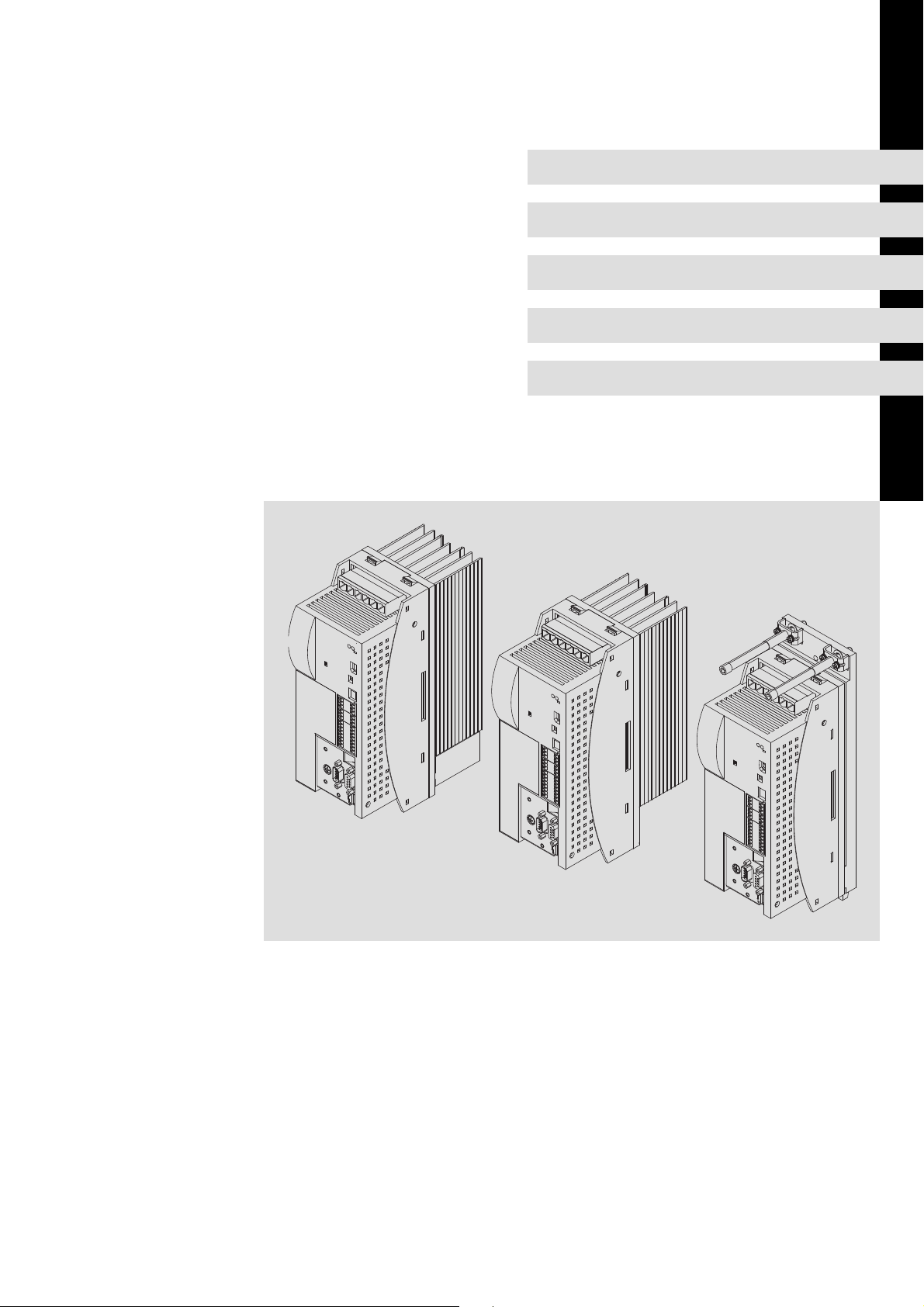
ECSEA_003A
EDBCSXM064 EN 11.0
3
Page 4

Scope of supply
Position Description Quantity
A ECSM... axis module 1
Accessory kit with fixing material corresponding to the design ():
l "E" − standard panel−mounted unit
l "D" − push−through technique
l "C" − cold−plate technique
Mounting Instructions 1
Drilling jig 1
Functional earth conductor (only ECSDM...) 1
Note!
The ECSZA000X0B connector set must be ordered separately.
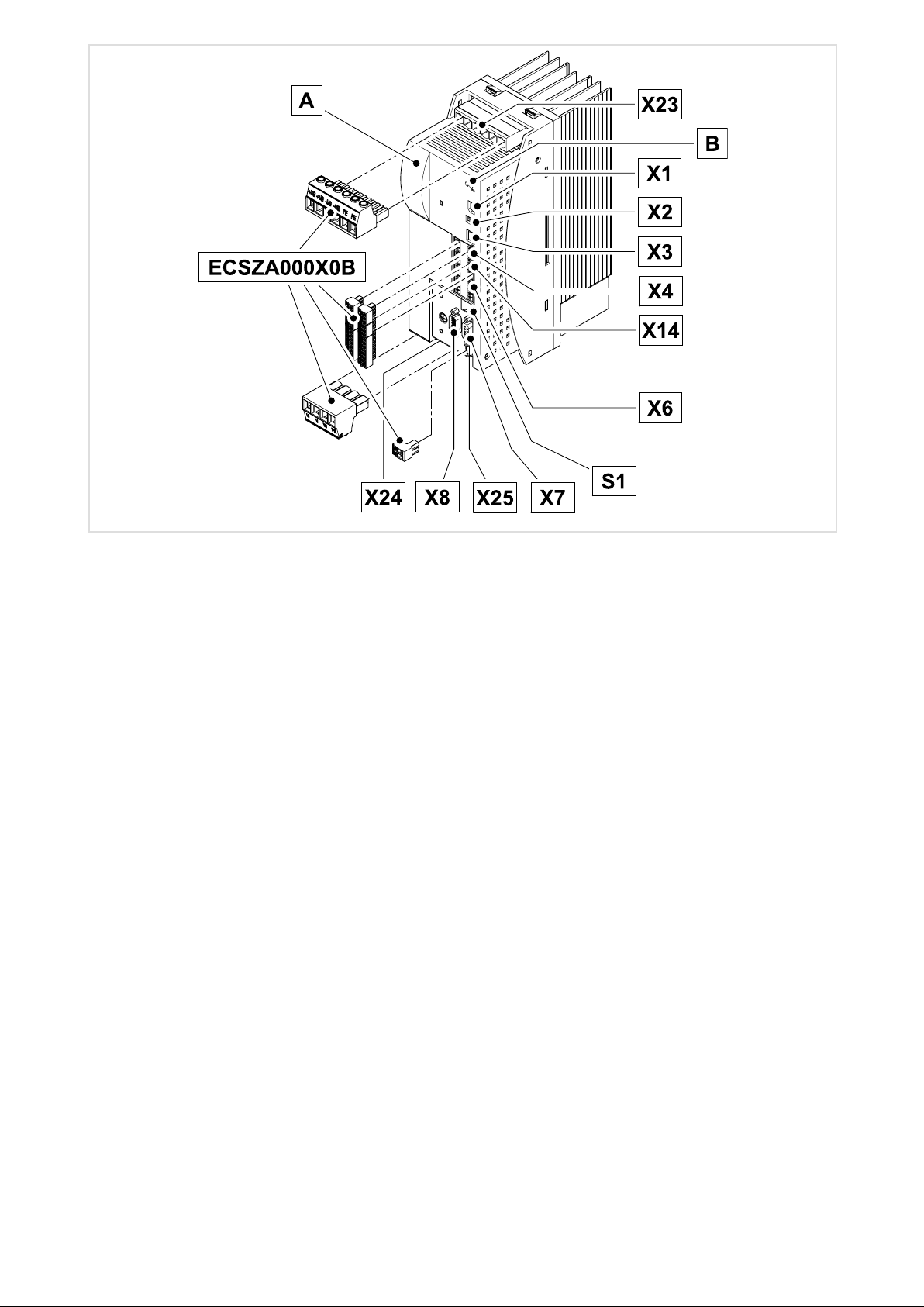
Connections and interfaces
Position Description Detailed
X23 Connections
l DC−bus voltage
l PE
B LEDs: Status and fault display
X1 Automation interface (AIF) for
l Communication module
l Operating module (keypad XT)
x2 PE connection of AIF
X3 Analog input configuration 69
X4 CAN connection
l MotionBus (CAN) / for ECSxA: System bus (CAN)
l Interface to the master control
X14 CAN−AUXconnection
l System bus (CAN)
l PC interface/HMI for parameter setting and diagnostics
X6 Connections
l Low−voltage supply
l Digital inputs and outputs
l Analog input
l "Safe torque off" (formerly "safe standstill")
S1 DIP switch
l CAN node address
l CAN baud rate
X7 Resolver connection 86
X8 Encoder connection
l Incremental encoder (TTL encoder)
l Sin/cos encoder
X25 Brake control connection 61
X24 Motor connection 60
54
79
191
80
64
68
69
70
197
87
1
information
Status displays
LED
Red Green
Off On Controller enabled, no fault
Off Blinking Controller inhibited (CINH), switch−on inhibit Code C0183
Blinking Off Fault/error (TRIP) active Code C0168/1
Blinking On Warning/FAIL−QSP active Code C0168/1
4
Operating state Check
EDBCSXM064 EN 11.0
Page 5

Contents i
1 Preface and general information 11 . . . . . . . . . . . . . . . . . . . . . . . . . . . . . . . . . . . . . . . . . . . .
1.1 About these Operating Instructions 11 . . . . . . . . . . . . . . . . . . . . . . . . . . . . . . . . . . . . .
1.1.1 Terminology used 12 . . . . . . . . . . . . . . . . . . . . . . . . . . . . . . . . . . . . . . . . . . . .
1.1.2 Code descriptions 13 . . . . . . . . . . . . . . . . . . . . . . . . . . . . . . . . . . . . . . . . . . . . .
1.2 Features of the axis module ECSxM (Motion) 14 . . . . . . . . . . . . . . . . . . . . . . . . . . . . .
1.3 Structure 15 . . . . . . . . . . . . . . . . . . . . . . . . . . . . . . . . . . . . . . . . . . . . . . . . . . . . . . . . . . . .
1.4 Scope of supply 16 . . . . . . . . . . . . . . . . . . . . . . . . . . . . . . . . . . . . . . . . . . . . . . . . . . . . . .
1.5 Legal regulations 17 . . . . . . . . . . . . . . . . . . . . . . . . . . . . . . . . . . . . . . . . . . . . . . . . . . . . .
2 Safety instructions 18 . . . . . . . . . . . . . . . . . . . . . . . . . . . . . . . . . . . . . . . . . . . . . . . . . . . . . . . .
2.1 General safety and application notes for Lenze controllers 18 . . . . . . . . . . . . . . . . . .
2.2 Thermal motor monitoring 22 . . . . . . . . . . . . . . . . . . . . . . . . . . . . . . . . . . . . . . . . . . . .
2.2.1 Forced ventilated or naturally ventilated motors 23 . . . . . . . . . . . . . . . . . .
2.2.2 Self−ventilated motors 24 . . . . . . . . . . . . . . . . . . . . . . . . . . . . . . . . . . . . . . . . .
2.3 Residual hazards 26 . . . . . . . . . . . . . . . . . . . . . . . . . . . . . . . . . . . . . . . . . . . . . . . . . . . . .
2.4 Safety instructions for the installation according to UL 28 . . . . . . . . . . . . . . . . . . . . .
2.5 Notes used 29 . . . . . . . . . . . . . . . . . . . . . . . . . . . . . . . . . . . . . . . . . . . . . . . . . . . . . . . . . .
3 Technical data 30 . . . . . . . . . . . . . . . . . . . . . . . . . . . . . . . . . . . . . . . . . . . . . . . . . . . . . . . . . . . .
3.1 General data and operating conditions 30 . . . . . . . . . . . . . . . . . . . . . . . . . . . . . . . . .
3.2 Rated data 32 . . . . . . . . . . . . . . . . . . . . . . . . . . . . . . . . . . . . . . . . . . . . . . . . . . . . . . . . . .
3.3 Current characteristics 34 . . . . . . . . . . . . . . . . . . . . . . . . . . . . . . . . . . . . . . . . . . . . . . . .
3.3.1 Increased continuous current depending on the control factor 34 . . . . . . .
3.3.2 Device protection by current derating 37 . . . . . . . . . . . . . . . . . . . . . . . . . . . .
4 Mechanical installation 38 . . . . . . . . . . . . . . . . . . . . . . . . . . . . . . . . . . . . . . . . . . . . . . . . . . . .
4.1 Important notes 38 . . . . . . . . . . . . . . . . . . . . . . . . . . . . . . . . . . . . . . . . . . . . . . . . . . . . . .
4.2 Mounting with fixing rails (standard installation) 39 . . . . . . . . . . . . . . . . . . . . . . . . .
4.2.1 Dimensions 39 . . . . . . . . . . . . . . . . . . . . . . . . . . . . . . . . . . . . . . . . . . . . . . . . . .
4.2.2 Mounting steps 40 . . . . . . . . . . . . . . . . . . . . . . . . . . . . . . . . . . . . . . . . . . . . . .
4.3 Mounting with thermal separation (push−through technique) 41 . . . . . . . . . . . . . . .
4.3.1 Dimensions 42 . . . . . . . . . . . . . . . . . . . . . . . . . . . . . . . . . . . . . . . . . . . . . . . . . .
4.3.2 Mounting steps 44 . . . . . . . . . . . . . . . . . . . . . . . . . . . . . . . . . . . . . . . . . . . . . .
4.4 Mounting in cold−plate design 45 . . . . . . . . . . . . . . . . . . . . . . . . . . . . . . . . . . . . . . . . . .
4.4.1 Dimensions 46 . . . . . . . . . . . . . . . . . . . . . . . . . . . . . . . . . . . . . . . . . . . . . . . . . .
4.4.2 Mounting steps 47 . . . . . . . . . . . . . . . . . . . . . . . . . . . . . . . . . . . . . . . . . . . . . .
EDBCSXM064 EN 11.0
5
Page 6

Contentsi
5 Electrical installation 48 . . . . . . . . . . . . . . . . . . . . . . . . . . . . . . . . . . . . . . . . . . . . . . . . . . . . . . .
5.1 Installation according to EMC (installation of a CE−typical drive system) 48 . . . . . . .
5.2 Power terminals 51 . . . . . . . . . . . . . . . . . . . . . . . . . . . . . . . . . . . . . . . . . . . . . . . . . . . . .
5.2.1 Connection to the DC bus (+UG, −UG) 54 . . . . . . . . . . . . . . . . . . . . . . . . . . . .
5.2.2 Connection plan for mimimum wiring with internal
brake resistor 56 . . . . . . . . . . . . . . . . . . . . . . . . . . . . . . . . . . . . . . . . . . . . . . . .
5.2.3 Connection plan for mimimum wiring with external
brake resistor 58 . . . . . . . . . . . . . . . . . . . . . . . . . . . . . . . . . . . . . . . . . . . . . . . .
5.2.4 Motor connection 60 . . . . . . . . . . . . . . . . . . . . . . . . . . . . . . . . . . . . . . . . . . . .
5.2.5 Motor holding brake connection 61 . . . . . . . . . . . . . . . . . . . . . . . . . . . . . . . .
5.2.6 Connection of an ECSxK... capacitor module (optional) 63 . . . . . . . . . . . . . .
5.3 Control terminals 64 . . . . . . . . . . . . . . . . . . . . . . . . . . . . . . . . . . . . . . . . . . . . . . . . . . . .
5.3.1 Digital inputs and outputs 68 . . . . . . . . . . . . . . . . . . . . . . . . . . . . . . . . . . . . .
5.3.2 Analog input 69 . . . . . . . . . . . . . . . . . . . . . . . . . . . . . . . . . . . . . . . . . . . . . . . . .
5.3.3 Safe torque off 70 . . . . . . . . . . . . . . . . . . . . . . . . . . . . . . . . . . . . . . . . . . . . . . .
5.4 Automation interface (AIF) 79 . . . . . . . . . . . . . . . . . . . . . . . . . . . . . . . . . . . . . . . . . . . . .
5.5 Wiring of system bus (CAN) 80 . . . . . . . . . . . . . . . . . . . . . . . . . . . . . . . . . . . . . . . . . . .
5.6 Wiring of the feedback system 85 . . . . . . . . . . . . . . . . . . . . . . . . . . . . . . . . . . . . . . . . .
5.6.1 Resolver connection 86 . . . . . . . . . . . . . . . . . . . . . . . . . . . . . . . . . . . . . . . . . . .
5.6.2 Encoder connection 87 . . . . . . . . . . . . . . . . . . . . . . . . . . . . . . . . . . . . . . . . . . .
5.6.3 Digital frequency input/output (encoder simulation) 90 . . . . . . . . . . . . . . .
6 Commissioning 92 . . . . . . . . . . . . . . . . . . . . . . . . . . . . . . . . . . . . . . . . . . . . . . . . . . . . . . . . . . .
6.1 Before you start 92 . . . . . . . . . . . . . . . . . . . . . . . . . . . . . . . . . . . . . . . . . . . . . . . . . . . . . .
6.2 Commissioning steps (overview) 93 . . . . . . . . . . . . . . . . . . . . . . . . . . . . . . . . . . . . . . . .
6.2.1 Basic settings with GDC 94 . . . . . . . . . . . . . . . . . . . . . . . . . . . . . . . . . . . . . . .
6.2.2 Setting of homing 96 . . . . . . . . . . . . . . . . . . . . . . . . . . . . . . . . . . . . . . . . . . . .
6.3 Loading the Lenze setting 100 . . . . . . . . . . . . . . . . . . . . . . . . . . . . . . . . . . . . . . . . . . . . . .
6.4 Setting of mains data 101 . . . . . . . . . . . . . . . . . . . . . . . . . . . . . . . . . . . . . . . . . . . . . . . . .
6.4.1 Selecting the function of the charging current limitation 101 . . . . . . . . . . .
6.4.2 Setting the voltage thresholds 102 . . . . . . . . . . . . . . . . . . . . . . . . . . . . . . . . .
6.5 Entry of motor data for Lenze motors 103 . . . . . . . . . . . . . . . . . . . . . . . . . . . . . . . . . . . .
6.6 Holding brake configuration 105 . . . . . . . . . . . . . . . . . . . . . . . . . . . . . . . . . . . . . . . . . . .
6.6.1 Closing the brake 107 . . . . . . . . . . . . . . . . . . . . . . . . . . . . . . . . . . . . . . . . . . . . .
6.6.2 Opening the brake 108 . . . . . . . . . . . . . . . . . . . . . . . . . . . . . . . . . . . . . . . . . . . .
6
EDBCSXM064 EN 11.0
Page 7

Contents i
6.7 Setting of the feedback system for position and speed control 109 . . . . . . . . . . . . . . .
6.7.1 Resolver as position and speed encoder 110 . . . . . . . . . . . . . . . . . . . . . . . . . .
6.7.2 Resolver as absolute value encoder 112 . . . . . . . . . . . . . . . . . . . . . . . . . . . . . .
6.7.3 TTL/SinCos encoder as position and speed encoder 113 . . . . . . . . . . . . . . . .
6.7.4 TTL/SinCos encoder as position encoder and resolver
as speed encoder 117 . . . . . . . . . . . . . . . . . . . . . . . . . . . . . . . . . . . . . . . . . . . . .
6.7.5 Absolute value encoder as position and speed encoder 121 . . . . . . . . . . . . .
6.7.6 Absolute value encoder as position encoder and resolver
as speed encoder 126 . . . . . . . . . . . . . . . . . . . . . . . . . . . . . . . . . . . . . . . . . . . . .
6.8 Selecting the control interface (C4010) 130 . . . . . . . . . . . . . . . . . . . . . . . . . . . . . . . . . .
6.9 Process data to the axis module (control word Ctrl1 and setpoints) 131 . . . . . . . . . .
6.10 Process data from the axis module (status words and actual values) 134 . . . . . . . . .
6.10.1 Toggle−bit monitoring 136 . . . . . . . . . . . . . . . . . . . . . . . . . . . . . . . . . . . . . . . . .
6.11 Entry of machine parameters 138 . . . . . . . . . . . . . . . . . . . . . . . . . . . . . . . . . . . . . . . . . .
6.12 Configuring the digital inputs and outputs 140 . . . . . . . . . . . . . . . . . . . . . . . . . . . . . . .
6.12.1 Digital inputs for communication via the
MotionBus (CAN) X4 141 . . . . . . . . . . . . . . . . . . . . . . . . . . . . . . . . . . . . . . . . . .
6.12.2 Digital inputs for communication via the
automation interface (AIF) X1 141 . . . . . . . . . . . . . . . . . . . . . . . . . . . . . . . . . .
6.12.3 Setting the polarity of digital inputs and outputs 142 . . . . . . . . . . . . . . . . . .
6.13 Setting of homing parameters 143 . . . . . . . . . . . . . . . . . . . . . . . . . . . . . . . . . . . . . . . . . .
6.13.1 Homing parameters 143 . . . . . . . . . . . . . . . . . . . . . . . . . . . . . . . . . . . . . . . . . .
6.13.2 Homing modes 145 . . . . . . . . . . . . . . . . . . . . . . . . . . . . . . . . . . . . . . . . . . . . . . .
6.13.3 Shifting the zero position with regard to the home position
(offsets C3011, C3012) 155 . . . . . . . . . . . . . . . . . . . . . . . . . . . . . . . . . . . . . . . .
6.13.4 Example: Reference search with linear positioning axis 156 . . . . . . . . . . . .
6.13.5 Example: Reference search with continuous positioning axis 158 . . . . . . . .
6.14 Selection of the operating mode 160 . . . . . . . . . . . . . . . . . . . . . . . . . . . . . . . . . . . . . . . .
6.14.1 Operating mode "Interpolated Position Mode" (IP−Mode) 161 . . . . . . . . . . .
6.14.2 "Homing" operating mode 164 . . . . . . . . . . . . . . . . . . . . . . . . . . . . . . . . . . . . .
6.14.3 "Manual jog" operating mode 165 . . . . . . . . . . . . . . . . . . . . . . . . . . . . . . . . . .
6.14.4 "Velocity" operating mode 167 . . . . . . . . . . . . . . . . . . . . . . . . . . . . . . . . . . . . .
6.15 Controller enable (CINH = 0) 169 . . . . . . . . . . . . . . . . . . . . . . . . . . . . . . . . . . . . . . . . . . .
6.16 Following error monitoring (C3030, C3031) 170 . . . . . . . . . . . . . . . . . . . . . . . . . . . . . .
6.17 Evaluating and retracting from hardware limit switch 172 . . . . . . . . . . . . . . . . . . . . .
6.17.1 Evaluating hardware limit switches 172 . . . . . . . . . . . . . . . . . . . . . . . . . . . . .
6.17.2 Retracting from hardware limit switches 172 . . . . . . . . . . . . . . . . . . . . . . . . .
6.18 Quick stop (QSP) 173 . . . . . . . . . . . . . . . . . . . . . . . . . . . . . . . . . . . . . . . . . . . . . . . . . . . . .
EDBCSXM064 EN 11.0
7
Page 8

Contentsi
6.19 Operation with motors from other manufacturers 174 . . . . . . . . . . . . . . . . . . . . . . . .
6.19.1 Entering motor data manually 174 . . . . . . . . . . . . . . . . . . . . . . . . . . . . . . . . . .
6.19.2 Checking the direction of rotation of the motor feedback system 177 . . . .
6.19.3 Adjusting current controller 178 . . . . . . . . . . . . . . . . . . . . . . . . . . . . . . . . . . . .
6.19.4 Effecting rotor position adjustment 180 . . . . . . . . . . . . . . . . . . . . . . . . . . . . .
6.20 Optimising the drive behaviour after start 183 . . . . . . . . . . . . . . . . . . . . . . . . . . . . . . . .
6.20.1 Speed controller adjustment 183 . . . . . . . . . . . . . . . . . . . . . . . . . . . . . . . . . . .
6.20.2 Adjustment of field controller and field weakening controller 185 . . . . . . .
6.20.3 Resolver adjustment 188 . . . . . . . . . . . . . . . . . . . . . . . . . . . . . . . . . . . . . . . . . .
7 Parameter setting 189 . . . . . . . . . . . . . . . . . . . . . . . . . . . . . . . . . . . . . . . . . . . . . . . . . . . . . . . . .
7.1 General information 189 . . . . . . . . . . . . . . . . . . . . . . . . . . . . . . . . . . . . . . . . . . . . . . . . .
7.2 Parameter setting with "Global Drive Control" (GDC) 190 . . . . . . . . . . . . . . . . . . . . . .
7.3 Parameter setting with the XT EMZ9371BC keypad 191 . . . . . . . . . . . . . . . . . . . . . . . .
7.3.1 Connecting the keypad 191 . . . . . . . . . . . . . . . . . . . . . . . . . . . . . . . . . . . . . . . .
7.3.2 Description of the display elements 192 . . . . . . . . . . . . . . . . . . . . . . . . . . . . .
7.3.3 Description of the function keys 194 . . . . . . . . . . . . . . . . . . . . . . . . . . . . . . . .
7.3.4 Changing and saving parameters 195 . . . . . . . . . . . . . . . . . . . . . . . . . . . . . . .
8 Configuration 196 . . . . . . . . . . . . . . . . . . . . . . . . . . . . . . . . . . . . . . . . . . . . . . . . . . . . . . . . . . . . .
8.1 Configuring MotionBus/system bus (CAN) 197 . . . . . . . . . . . . . . . . . . . . . . . . . . . . . . .
8.1.1 Setting CAN node address and baud rate 197 . . . . . . . . . . . . . . . . . . . . . . . . .
8.1.2 Individual addressing 201 . . . . . . . . . . . . . . . . . . . . . . . . . . . . . . . . . . . . . . . . .
8.1.3 Defining boot−up master in the drive system 203 . . . . . . . . . . . . . . . . . . . . . .
8.1.4 Setting of boot−up time/cycle time 204 . . . . . . . . . . . . . . . . . . . . . . . . . . . . . .
8.1.5 Executing a reset node 206 . . . . . . . . . . . . . . . . . . . . . . . . . . . . . . . . . . . . . . . .
8.1.6 Axis synchronisation (CAN synchronisation) 207 . . . . . . . . . . . . . . . . . . . . . .
8.1.7 Monitoring of the synchronisation (sync time slot) 209 . . . . . . . . . . . . . . . . .
8.1.8 Axis synchronisation via CAN 210 . . . . . . . . . . . . . . . . . . . . . . . . . . . . . . . . . . .
8.1.9 Axis synchronisation via terminal X6/DI1 211 . . . . . . . . . . . . . . . . . . . . . . . . .
8.2 Node guarding 212 . . . . . . . . . . . . . . . . . . . . . . . . . . . . . . . . . . . . . . . . . . . . . . . . . . . . . .
8.3 Diagnostics codes 214 . . . . . . . . . . . . . . . . . . . . . . . . . . . . . . . . . . . . . . . . . . . . . . . . . . . .
8.3.1 CAN bus status (C0359) 214 . . . . . . . . . . . . . . . . . . . . . . . . . . . . . . . . . . . . . . . .
8.3.2 CAN telegram counter (C0360) 215 . . . . . . . . . . . . . . . . . . . . . . . . . . . . . . . . .
8.3.3 CAN bus load (C0361) 216 . . . . . . . . . . . . . . . . . . . . . . . . . . . . . . . . . . . . . . . . .
8.4 Remote parameterisation (gateway function) 217 . . . . . . . . . . . . . . . . . . . . . . . . . . . .
8
EDBCSXM064 EN 11.0
Page 9

Contents i
9 Monitoring functions 219 . . . . . . . . . . . . . . . . . . . . . . . . . . . . . . . . . . . . . . . . . . . . . . . . . . . . . .
9.1 Fault responses 220 . . . . . . . . . . . . . . . . . . . . . . . . . . . . . . . . . . . . . . . . . . . . . . . . . . . . . .
9.2 Overview of monitoring functions 221 . . . . . . . . . . . . . . . . . . . . . . . . . . . . . . . . . . . . . .
9.3 Configuring monitoring functions 225 . . . . . . . . . . . . . . . . . . . . . . . . . . . . . . . . . . . . . .
9.3.1 Monitoring times for process data input objects 225 . . . . . . . . . . . . . . . . . . .
9.3.2 Time−out monitoring for activated remote parameterisation 227 . . . . . . . .
9.3.3 Short circuit monitoring (OC1) 228 . . . . . . . . . . . . . . . . . . . . . . . . . . . . . . . . . .
9.3.4 Earth fault monitoring (OC2) 228 . . . . . . . . . . . . . . . . . . . . . . . . . . . . . . . . . . .
9.3.5 Motor temperature monitoring (OH3, OH7) 229 . . . . . . . . . . . . . . . . . . . . . .
9.3.6 Heatsink temperature monitoring (OH, OH4) 231 . . . . . . . . . . . . . . . . . . . . .
9.3.7 Monitoring of internal device temperature (OH1, OH5) 232 . . . . . . . . . . . . .
9.3.8 Function monitoring of thermal sensors (H10, H11) 233 . . . . . . . . . . . . . . . .
9.3.9 Current load of controller (I x t monitoring: OC5, OC7) 234 . . . . . . . . . . . . . .
9.3.10 Current load of motor (I2 x t monitoring: OC6, OC8) 237 . . . . . . . . . . . . . . . .
9.3.11 DC−bus voltage monitoring (OU, LU) 241 . . . . . . . . . . . . . . . . . . . . . . . . . . . . .
9.3.12 Voltage supply monitoring − control electronics (U15) 244 . . . . . . . . . . . . . .
9.3.13 Motor phase failure monitoring (LP1) 244 . . . . . . . . . . . . . . . . . . . . . . . . . . . .
9.3.14 Monitoring of the resolver cable (Sd2) 245 . . . . . . . . . . . . . . . . . . . . . . . . . . .
9.3.15 Motor temperature sensor monitoring (Sd6) 246 . . . . . . . . . . . . . . . . . . . . . .
9.3.16 Monitoring of the absolute value encoder initialisation (Sd7) 247 . . . . . . . .
9.3.17 Sin/cos signal monitoring (Sd8) 248 . . . . . . . . . . . . . . . . . . . . . . . . . . . . . . . . .
9.3.18 Monitoring of the speed system deviation (nErr) 249 . . . . . . . . . . . . . . . . . . .
9.3.19 Monitoring of max. system speed (NMAX) 250 . . . . . . . . . . . . . . . . . . . . . . . .
9.3.20 Monitoring of the rotor position adjustment (PL) 251 . . . . . . . . . . . . . . . . . .
10 Diagnostics 252 . . . . . . . . . . . . . . . . . . . . . . . . . . . . . . . . . . . . . . . . . . . . . . . . . . . . . . . . . . . . . . .
10.1 Diagnostics with Global Drive Control (GDC) 252 . . . . . . . . . . . . . . . . . . . . . . . . . . . . . .
10.2 Diagnostics with Global Drive Oscilloscope (GDO) 253 . . . . . . . . . . . . . . . . . . . . . . . . .
10.2.1 GDO buttons 254 . . . . . . . . . . . . . . . . . . . . . . . . . . . . . . . . . . . . . . . . . . . . . . . . .
10.2.2 Diagnostics with GDO 255 . . . . . . . . . . . . . . . . . . . . . . . . . . . . . . . . . . . . . . . . .
10.3 Diagnostics with the XT EMZ9371BC keypad 259 . . . . . . . . . . . . . . . . . . . . . . . . . . . . .
10.4 Diagnostics with PCAN−View 260 . . . . . . . . . . . . . . . . . . . . . . . . . . . . . . . . . . . . . . . . . . .
10.4.1 Monitoring of telegram traffic on the CAN bus 260 . . . . . . . . . . . . . . . . . . . .
10.4.2 Setting all CAN nodes to the "Operational" status 262 . . . . . . . . . . . . . . . . .
EDBCSXM064 EN 11.0
9
Page 10

Contentsi
11 Troubleshooting and fault elimination 263 . . . . . . . . . . . . . . . . . . . . . . . . . . . . . . . . . . . . . . .
11.1 Fault analysis 263 . . . . . . . . . . . . . . . . . . . . . . . . . . . . . . . . . . . . . . . . . . . . . . . . . . . . . . . .
11.1.1 Fault analysis via the LED display 263 . . . . . . . . . . . . . . . . . . . . . . . . . . . . . . . .
11.1.2 Fault analysis with keypad XT EMZ9371BC 263 . . . . . . . . . . . . . . . . . . . . . . .
11.1.3 Fault analysis with the history buffer 264 . . . . . . . . . . . . . . . . . . . . . . . . . . . .
11.1.4 Fault analysis via application status word (C3150/C3151) 266 . . . . . . . . . . .
11.1.5 Fault analysis via LECOM status words (C0150/C0155) 267 . . . . . . . . . . . . .
11.2 Malfunction of the drive 269 . . . . . . . . . . . . . . . . . . . . . . . . . . . . . . . . . . . . . . . . . . . . . . .
11.3 Fault messages 270 . . . . . . . . . . . . . . . . . . . . . . . . . . . . . . . . . . . . . . . . . . . . . . . . . . . . . .
11.3.1 Causes and remedies 270 . . . . . . . . . . . . . . . . . . . . . . . . . . . . . . . . . . . . . . . . . .
11.3.2 Reset fault messages (TRIP−RESET) 278 . . . . . . . . . . . . . . . . . . . . . . . . . . . . . . .
12 Appendix 279 . . . . . . . . . . . . . . . . . . . . . . . . . . . . . . . . . . . . . . . . . . . . . . . . . . . . . . . . . . . . . . . .
12.1 Code table 279 . . . . . . . . . . . . . . . . . . . . . . . . . . . . . . . . . . . . . . . . . . . . . . . . . . . . . . . . . .
12.2 General information about the system bus (CAN) 333 . . . . . . . . . . . . . . . . . . . . . . . . .
12.3 Communication with MotionBus/system bus (CAN) 334 . . . . . . . . . . . . . . . . . . . . . . .
12.3.1 Structure of the CAN data telegram 334 . . . . . . . . . . . . . . . . . . . . . . . . . . . . .
12.3.2 Communication phases of the CAN network (NMT) 336 . . . . . . . . . . . . . . . .
12.3.3 Process data transfer 339 . . . . . . . . . . . . . . . . . . . . . . . . . . . . . . . . . . . . . . . . . .
12.3.4 Parameter data transfer 345 . . . . . . . . . . . . . . . . . . . . . . . . . . . . . . . . . . . . . . .
12.3.5 Addressing of the parameter and process data objects 351 . . . . . . . . . . . . .
12.4 Overview of accessories 353 . . . . . . . . . . . . . . . . . . . . . . . . . . . . . . . . . . . . . . . . . . . . . . .
12.4.1 Connector sets 353 . . . . . . . . . . . . . . . . . . . . . . . . . . . . . . . . . . . . . . . . . . . . . . .
12.4.2 Shield mounting kit 353 . . . . . . . . . . . . . . . . . . . . . . . . . . . . . . . . . . . . . . . . . . .
12.4.3 Components for operation and communication 354 . . . . . . . . . . . . . . . . . . .
12.4.4 Brake resistor 355 . . . . . . . . . . . . . . . . . . . . . . . . . . . . . . . . . . . . . . . . . . . . . . . .
12.4.5 Mains fuses 357 . . . . . . . . . . . . . . . . . . . . . . . . . . . . . . . . . . . . . . . . . . . . . . . . . .
12.4.6 Mains chokes 358 . . . . . . . . . . . . . . . . . . . . . . . . . . . . . . . . . . . . . . . . . . . . . . . .
12.4.7 RFI filters 359 . . . . . . . . . . . . . . . . . . . . . . . . . . . . . . . . . . . . . . . . . . . . . . . . . . . .
13 Index 360 . . . . . . . . . . . . . . . . . . . . . . . . . . . . . . . . . . . . . . . . . . . . . . . . . . . . . . . . . . . . . . . . . . . .
10
EDBCSXM064 EN 11.0
Page 11

Preface and general information
About these Operating Instructions
1 Preface and general information
1.1 About these Operating Instructions
These Operating Instructions will assist you in connecting and commissioning the ECSxM...
axis modules.
They contain safety instructions which must be observed!
All persons working on and with the ECSxM... axis modules must have the Operating
Instructions available and must observe the information and notes relevant for their work.
The Operating Instructions must always be in a complete and perfectly readable state.
1
EDBCSXM064 EN 11.0
11
Page 12

1
Preface and general information
About these Operating Instructions
Terminology used
1.1.1 Terminology used
Term In the following text used for
Power supply module
ECSxE...
Capacitor module
ECSxK...
Axis module
Controller
Standard device
ECSxS...
ECSxP...
ECSxM...
ECSxA ...
Drive system ECS drive system consisting of:
24 V supply
Low−voltage supply
AIF Automation InterFace
System bus (CAN) Lenze standard bus system based on CANopen for
MotionBus (CAN) The "MotionBus (CAN)" term expresses the functionality of the CAN interface X4 in
DDS Drive PLC Developer Studio
GDC Global Drive Control
GDO Global Drive Oscilloscope
Cxxxx Code Cxxxx (e.g. C0351)
Cxxxx/y Subcode y of code Cxxxx (e. g. C0470/3 = subcode 3 of code C0470)
Xk/y Terminal y on terminal strip Xk (e.g. X6/B+ = terminal B+ on terminal strip X6)
ECSxE... power supply module
ECSxK... capacitor module
Axis module of the ECS series
l ECSxS... − "Speed and Torque"
l ECSxP... − "Posi and Shaft"
l ECSxM... − "Motion"
l ECSxA... − "Application"
l ECSxE... power supply module
l Axis module ECSxS... / ECSxP... / ECSxM... / ECSxA...
l ECSxK series capacitor module (optional)
l further Lenze drive components (accessories)
Voltage supply
l of the control card, voltage range 20 ... 30 V DC (±0 V)
l of the "safe torque off" function (formerly "safe standstill"), voltage range
18 ... 30 V DC (±0 V)
l of the motor holding brake, voltage range 23 ... 30 V DC (±0 V)
l communication with a higher−level host system (PLC) or further controllers.
l parameter setting and diagnostics.
case of ECSxS/P/M... axis modules, where communication takes place using a
higher−level host system (PLC) or further controllers exclusively via the X4 interface.
Interface X14 (CAN−AUX) is exclusively used for parameter setting and diagnostics.
(Lenze software for PLC programming acc. to IEC 61131)
(Lenze software for parameter setting and diagnostics)
(additional diagnostic tool of the GDC)
Parameters which serve to parameterise or monitor the controller.
12
EDBCSXM064 EN 11.0
Page 13

Preface and general information
About these Operating Instructions
Code descriptions
1.1.2 Code descriptions
Lenze codes are described in the form of tables with the following structure:
Column Abbreviation Meaning
No.
Name LCD display of the keypad XT EMZ9371BC
Lenze/{Appl.}
Selection 1 {%} 99 minimum value {unit}maximum value
IMPORTANT Short code description
Cxxxx
1 Subcode 1 of Cxxxx
2 Subcode 2 of Cxxxx
Cxxxx Changed input value of the code or subcode is accepted after pressing
[Cxxxx] Changed input value of the code or subcode is accepted after pressing
x Lenze setting:
{xxx...} Different application initialisation value
à The "Important" column contains further information
Code no. Cxxxx
.
when the controller is inhibited.
l Value at the time of delivery or after loading the Lenze setting using
C0002.
l Value at the time of delivery
l After loading the Lenze setting using C0002, the application
initialisation value is overwritten with the Lenze setting.
l The application initialisation values can be restored by loading the
application software with "Global Drive Loader" (GDL).
1
Example
Code Possible settings IMPORTANT
No. Designation Lenze/
{Appl.}
C0003 Par save 0
C1192 Selection of resistance
1 Char.: OHM 1000
2 Char.: OHM 2225 PTC characteristic:
Selection
Non−volatile saving of parameter
set
0 No response
1 Save parameter set
characteristic for PTC
0 {1 W} 30000 PTC characteristic:
{0}
resistance R1 at T1
resistance R2 at T2
EDBCSXM064 EN 11.0
13
Page 14

1
Preface and general information
Features of the axis module ECSxM (Motion)
1.2 Features of the axis module ECSxM (Motion)
ƒ Safety function "safe torque off" (formerly "safe standstill")
ƒ Homing can be selected from 19 modes
ƒ Brake logic activatable
ƒ Switching of operating modes
– "Interpolated Position Mode" (for travel according to setpoint selection)
– "Homing Mode"
– "Manual Jog"
– "Velocity Mode"
ƒ Torque feedforward control
ƒ Fine interpolation
ƒ Interpolation cycle can be selected between 1 − 10 ms
ƒ Process coordination by higher−level host system (PLC)
ƒ Toggle bit monitoring
ƒ Monitor data selectable via control word
ƒ Double CAN ON BORD
– MotionBus (CAN):
Interface X4 "CAN" (PDO1, Sync−based) for communicating with a higher−level
host system (PLC) or further controllers.
– System bus (CAN):
Interface X14 "CAN−AUX" for parameter setting and diagnostics
ƒ Selectable control interfaces (via code C4010):
– MotionBus (CAN)
– MotionBus (EtherCAT) via the automation interface (AIF)
– Via codes through parameter channel
ƒ Supported feedback systems:
– Resolver with and without position storage
– Encoder (incremental encoder (TTL encoder), sin/cos encoder)
ƒ Commissioning, parameter setting and diagnostics with the Lenze parameter
setting and operating program "Global Drive Control" (GDC) or the XT EMZ9371BC
keypad
14
EDBCSXM064 EN 11.0
Page 15
EDBCSXM064 EN 11.0
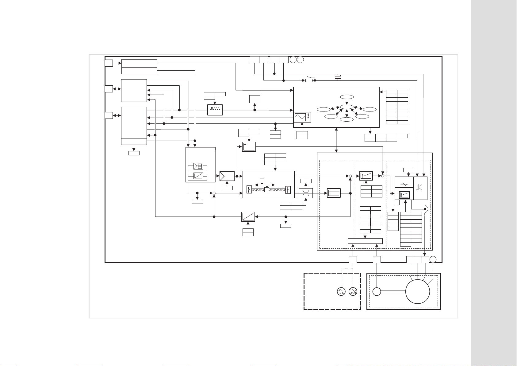
1.3 Structure
X6
X1
C4010 = 2
(AIF)
X4
C4010 = 0
(CAN)
Digital_IO
DI1: EtherCAT_SYNC
AIF_IO
CAN_IO
CAN_SYNC
C3165
Set position
(32 bits)
Actual position (32 bits)
C3162
Fine
interpolation
*
C0050
Toggle bit
+
-
UG+ UG- UG+ UG-
C3161C3160
C0011
*
C3430
C3420
C3422
C3152
C3153
Status word
C3421
C0011
C0497
Control word
Monitor data
C3150
C3151
C0935
C3010
C3012
C0936
C3011
Homing
C3030
C3032
C0051
PE PE
Drive control
C3180
C3181
C3034
C3031
C3033
Trouble
VelMode
Motor control
Position
control
1000 s
m
32 bits
Init
Stand by
Homing
IP-Mode
Speed
control
+
Feedback
250 s
C0019
C0071
C0105
C0030
C0095
C0416
C0420
C0427
C0491
C0540
ManJog
C0136
C3210
m
16 bits
C0070
C0072
C0909
C0058
C0098
C0419
C0421
C0490
C0495
C3001
C0150
C3211
+
C0135
C0576
C0579
C3002
C3009
C3008
C3010
C3011
C3012
C3020
C3022
C3021
C3037
C3038
C3170
C3175
C5000
C4011
C3201
C3200
C5001
Current/torque
control
m
62.5 s
PWM
VEC CTRL
C0022
C0053
C0074
C0079
C0082
C0076
C0083
C0078
C0092
C0081
C0085
C0088
C0090
C4018
C0018
ECSxM
16 bits
C0023
C0075
C0077
C0080
C0084
C0087
C0089
C0091
Preface and general information
15
Fig. 1−1 Structure of the ECS application "Motion"
alternative
TTL encoder
Sin/cos encoder
X8
X7
R
PE
WVU
M
3~
Structure
Motor
ECSXA502
1
Page 16

1
1.4 Scope of supply
Preface and general information
Scope of supply
The scope of supply of the ECSxM... axis module includes:
ƒ Standard device
ƒ Accessory kit with fixings according to the design:
– "E" − panel−mounted device
– "D" − push−through technique
– "C" − cold−plate technique
ƒ Mounting Instructions
ƒ Drilling jig
ƒ Functional earth conductor (only ECSDM...)
Accessories
The appendix includes information on the following accessories: ( 353).
ƒ Connector sets for
– power supply modules: ECSZE000X0B
– capacitor modules: ECSZK000X0B
– axis modules: ECSZA000X0B
ƒ ECSZS000X0B001 shield mounting kit (EMC accessories)
ƒ Components for operation and communication
ƒ Brake resistors
ƒ Mains fuses
ƒ Mains chokes
ƒ RFI filters
Tip!
Information and auxiliary devices related to the Lenze products can be found
in the download area at
http://www.Lenze.com
16
EDBCSXM064 EN 11.0
Page 17

1.5 Legal regulations
Preface and general information
Legal regulations
1
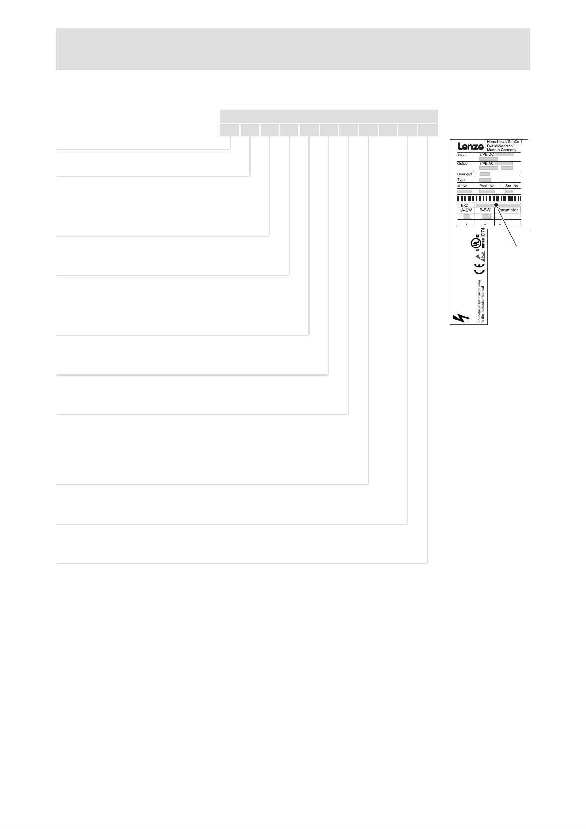
Identification
Application as
directed
Liability l The information, data and notes in these Instructions met the state of the art at the time of printing. Claims
Warranty l Terms of warranty: See terms of sales and delivery of Lenze Drive Systems GmbH.
Nameplate CE designation Manufacturer
Lenze controllers are
unambiguously designated by the
contents of the nameplate.
ECSxM... axis modules
l must only be operated under the conditions prescribed in these Instructions.
l are components
– for open and closed loop control of variable speed drives with PM synchronous motors and asynchronous
motors.
– for installation into a machine
– for assembly with other components to form a machine.
l are electrical equipment for the installation in control cabinets or similar closed operating areas.
l comply with the protective requirements of the EC Low−Voltage Directive.
l are not machines for the purpose of the EC Machinery Directive.
l are not to be used as domestic appliances, but for industrial purposes only.
Drive systems with ECSxM... axis modules
l comply with the EC Directive "Electromagnetic compatibility" if they are installed according to the guidelines
of CE−typical drive systems.
l can be used
– at public and non−public mains.
– in industrial premises.
l The user is responsible for the compliance of his application with the EC directives.
Any other use shall be deemed inappropriate!
on modifications referring to axis modules and components which have already been supplied cannot be
derived from the information, illustrations and descriptions given in these Instructions.
l The specifications, processes, and circuitry described in these Instructions are for guidance only and must be
adapted to your own specific application. Lenze does not take responsibility for the suitability of the process
and circuit proposals.
l Lenze does not accept any liability for damages and failures caused by:
– Disregarding the Operating Instructions
– Unauthorised modifications to the axis module
– Operating errors
– Improper working on and with the axis module
l Warranty claims must be made to Lenze immediately after detecting the deficiency or fault.
l The warranty is void in all cases where liability claims cannot be made.
Conforms to the EC Low−Voltage
Directive
Lenze Automation GmbH
Grünstraße 36
D−40667 Meerbusch
EDBCSXM064 EN 11.0
17
Page 18

2
Safety instructions
General safety and application notes for Lenze controllers
2 Safety instructions
2.1 General safety and application notes for Lenze controllers
(in accordance with Low−Voltage Directive 2006/95/EC)
For your personal safety
Disregarding the following safety measures can lead to severe injury to persons and
damage to material assets:
ƒ Only use the product as directed.
ƒ Never commission the product in the event of visible damage.
ƒ Never commission the product before assembly has been completed.
ƒ Do not carry out any technical changes on the product.
ƒ Only use the accessories approved for the product.
ƒ Only use original spare parts from Lenze.
ƒ Observe all regulations for the prevention of accidents, directives and laws
applicable on site.
ƒ Transport, installation, commissioning and maintenance work must only be carried
out by qualified personnel.
– Observe IEC 364 and CENELEC HD 384 or DIN VDE 0100 and IEC report 664 or
DIN VDE 0110 and all national regulations for the prevention of accidents.
– According to this basic safety information, qualified, skilled personnel are persons
who are familiar with the assembly, installation, commissioning, and operation of
the product and who have the qualifications necessary for their occupation.
ƒ Observe all specifications in this documentation.
– This is the condition for safe and trouble−free operation and the achievement of
the specified product features.
– The procedural notes and circuit details described in this documentation are only
proposals. It is up to the user to check whether they can be transferred to the
particular applications. Lenze Automation GmbH does not accept any liability for
the suitability of the procedures and circuit proposals described.
ƒ Depending on their degree of protection, some parts of the Lenze controllers
(frequency inverters, servo inverters, DC speed controllers) and their accessory
components can be live, moving and rotating during operation. Surfaces can be hot.
– Non−authorised removal of the required cover, inappropriate use, incorrect
installation or operation, creates the risk of severe injury to persons or damage to
material assets.
– For more information, please see the documentation.
18
ƒ High amounts of energy are produced in the controller. Therefore it is required to
wear personal protective equipment (body protection, headgear, eye protection, ear
protection, hand guard).
EDBCSXM064 EN 11.0
Page 19

Safety instructions
General safety and application notes for Lenze controllers
Application as directed
Controllers are components which are designed for installation in electrical systems or
machines. They are not to be used as domestic appliances, but only for industrial purposes
according to EN 61000−3−2.
When controllers are installed into machines, commissioning (i.e. starting of the operation
as directed) is prohibited until it is proven that the machine complies with the regulations
of the EC Directive 2006/42/EC (Machinery Directive); EN 60204 must be observed.
Commissioning (i.e. starting of the operation as directed) is only allowed when there is
compliance with the EMC Directive (2004/108/EC).
The controllers meet the requirements of the Low−Voltage Directive 2006/95/EC. The
harmonised standard EN 61800−5−1 applies to the controllers.
The technical data and supply conditions can be obtained from the nameplate and the
documentation. They must be strictly observed.
Warning: Controllers are products which can be installed in drive systems of category C2
according to EN 61800−3. These products can cause radio interferences in residential areas.
In this case, special measures can be necessary.
2
Transport, storage
Please observe the notes on transport, storage, and appropriate handling.
Observe the climatic conditions according to the technical data.
Installation
The controllers must be installed and cooled according to the instructions given in the
corresponding documentation.
The ambient air must not exceed degree of pollution 2 according to EN 61800−5−1.
Ensure proper handling and avoid excessive mechanical stress. Do not bend any
components and do not change any insulation distances during transport or handling. Do
not touch any electronic components and contacts.
Controllers contain electrostatic sensitive devices which can easily be damaged by
inappropriate handling. Do not damage or destroy any electrical components since this
might endanger your health!
EDBCSXM064 EN 11.0
19
Page 20

2
Safety instructions
General safety and application notes for Lenze controllers
Electrical connection
When working on live controllers, observe the applicable national regulations for the
prevention of accidents (e.g. VBG 4).
The electrical installation must be carried out according to the appropriate regulations
(e.g. cable cross−sections, fuses, PE connection). Additional information can be obtained
from the documentation.
This documentation contains information on installation in compliance with EMC
(shielding, earthing, filter, and cables). These notes must also be observed for CE−marked
controllers. The manufacturer of the system is responsible for compliance with the limit
values demanded by EMC legislation. The controllers must be installed in housings (e.g.
control cabinets) to meet the limit values for radio interferences valid at the site of
installation. The housings must enable an EMC−compliant installation. Observe in
particular that e.g. the control cabinet doors have a circumferential metal connection to
the housing. Reduce housing openings and cutouts to a minimum.
Lenze controllers may cause a DC current in the PE conductor. If a residual current device
(RCD) is used for protection against direct or indirect contact for a controller with
three−phase supply, only a residual current device (RCD) of type B is permissible on the
supply side of the controller. If the controller has a single−phase supply, a residual current
device (RCD) of type A is also permissible. Apart from using a residual current device (RCD),
other protective measures can be taken as well, e.g. electrical isolation by double or
reinforced insulation or isolation from the supply system by means of a transformer.
Operation
If necessary, systems including controllers must be equipped with additional monitoring
and protection devices according to the valid safety regulations (e.g. law on technical
equipment, regulations for the prevention of accidents). The controllers can be adapted to
your application. Please observe the corresponding information given in the
documentation.
After the controller has been disconnected from the supply voltage, all live components
and power terminals must not be touched immediately because capacitors can still be
charged. Please observe the corresponding stickers on the controller.
All protection covers and doors must be shut during operation.
Notes for UL−approved systems with integrated controllers: UL warnings are notes that
only apply to UL systems. The documentation contains special UL notes.
20
EDBCSXM064 EN 11.0
Page 21

Safety instructions
General safety and application notes for Lenze controllers
Safety functions
Certain controller versions support safety functions (e.g. "Safe torque off", formerly "Safe
standstill") according to the requirements of the EC Directive 2006/42/EC (Machinery
Directive). The notes on the integrated safety system provided in this documentation must
be observed.
Maintenance and servicing
The controllers do not require any maintenance if the prescribed operating conditions are
observed.
Disposal
Recycle metal and plastic materials. Ensure professional disposal of assembled PCBs.
The product−specific safety and application notes given in these instructions must be
observed!
2
EDBCSXM064 EN 11.0
21
Page 22

2
Safety instructions
Thermal motor monitoring
2.2 Thermal motor monitoring
Note!
2
ƒ I
x t monitoring is based on a mathematical model which calculates a
thermal motor load from the detected motor currents.
ƒ The calculated motor load is saved when the mains is switched.
ƒ The function is UL−certified, i.e. no additional protective measures are
required for the motor in UL−approved systems.
ƒ However, I
the motor load could not be detected as for instance changed cooling
conditions (e.g. interrupted or too warm cooling air flow).
2
x t load of the motor is displayed in C0066.
Die I
The thermal loading capacity of the motor is expressed by the thermal motor time
constant (t, C0128). Find the value in the rated motor data or contact the manufacturer
of the motor.
2
The I
x t monitoring has been designed such that it will be activated after 179 s in the
event of a motor with a thermal motor time constant of 5 minutes (Lenze setting C0128),
a motor current of 1.5 x I
Two adjustable trigger thresholds provide for different responses.
2
x t monitoring is no full motor protection as other influences on
N
and a trigger threshold of 100 %.
ƒ Adjustable response OC8 (TRIP, warning, off).
– The trigger threshold is set in C0127.
– The response is set in C0606.
– The response OC8, for instance, can be used for an advance warning.
ƒ Fixed response OC6−TRIP.
– The trigger threshold is set in C0120.
Behaviour of the I2 x t monitoring Condition
The I2 x t monitoring is deactivated.
C0066 is set = 0 % and
MCTRL−LOAD−I2XT is set = 0.00 %.
I2 x t monitoring is stopped.
The current value in C0066 and at the
MCTRL−LOAD−I2XT output is frozen.
I2 x t monitoring is deactivated.
The motor load is displayed in C0066.
When C0120 = 0 % and C0127 = 0 %, set controller
inhibit.
When C0120 = 0 % and C0127 = 0 %, set controller
enable.
Set C0606 = 3 (off) and C0127 > 0 %.
Note!
An error message OC6 or OC8 can only be reset if the I2 x t load falls below the
set trigger threshold by 5 %.
22
EDBCSXM064 EN 11.0
Page 23
Forced ventilated or naturally ventilated motors
2.2.1 Forced ventilated or naturally ventilated motors
Parameter setting
2
The following codes can be set for I
Code Meaning Value range Lenze setting
C0066 Display of the I2 x t load of the motor 0 ... 250 % −
C0120 Threshold: Triggering of error "OC6" 0 ... 120 % 0 %
C0127 Threshold: Triggering of error "OC8" 0 ... 120 % 0 %
C0128 Thermal motor time constant 0.1 ... 50.0 min 5.0 min
C0606 Response to error "OC8" TRIP, warning, off Warning
x t monitoring:
Calculate release time and I2 x t load
Formula for release time Information
t +*(t) ln
ȡ
ȧ
ȧ
Ȣ
1 *
I
ȣ
z ) 1
I
Mot
ǒ
Ǔ
I
N
2
100
ȧ
ȧ
Ȥ
Mot
I
r
t Thermal motor time constant (C0128)
z Threshold value in C0120 (OC6) or C0127 (OC8)
Actual motor current (C0054)
Rated motor current (C0088)
Safety instructions
Thermal motor monitoring
2
Formulae for I2 x t load Information
L(t) Chronological sequence of the I2 x t load of the motor
2
I
Mot
ǒ
L(t) +
If the controller is inhibited, the I2 x t load is reduced:
Ǔ
100% ǒ1 * e
I
N
L(t) + L
Start
Ǹ
e
*t
t
t
*
t
I
Ǔ
Mot
Ir Rated motor current (C0088)
t Thermal motor time constant (C0128)
L
Start
(Display: C0066)
Actual motor current (C0054)
I2 x t load before controller inhibit
If an error is triggered, the value corresponds to the
threshold value set in C0120 (OC6) or
C0127 (OC8).
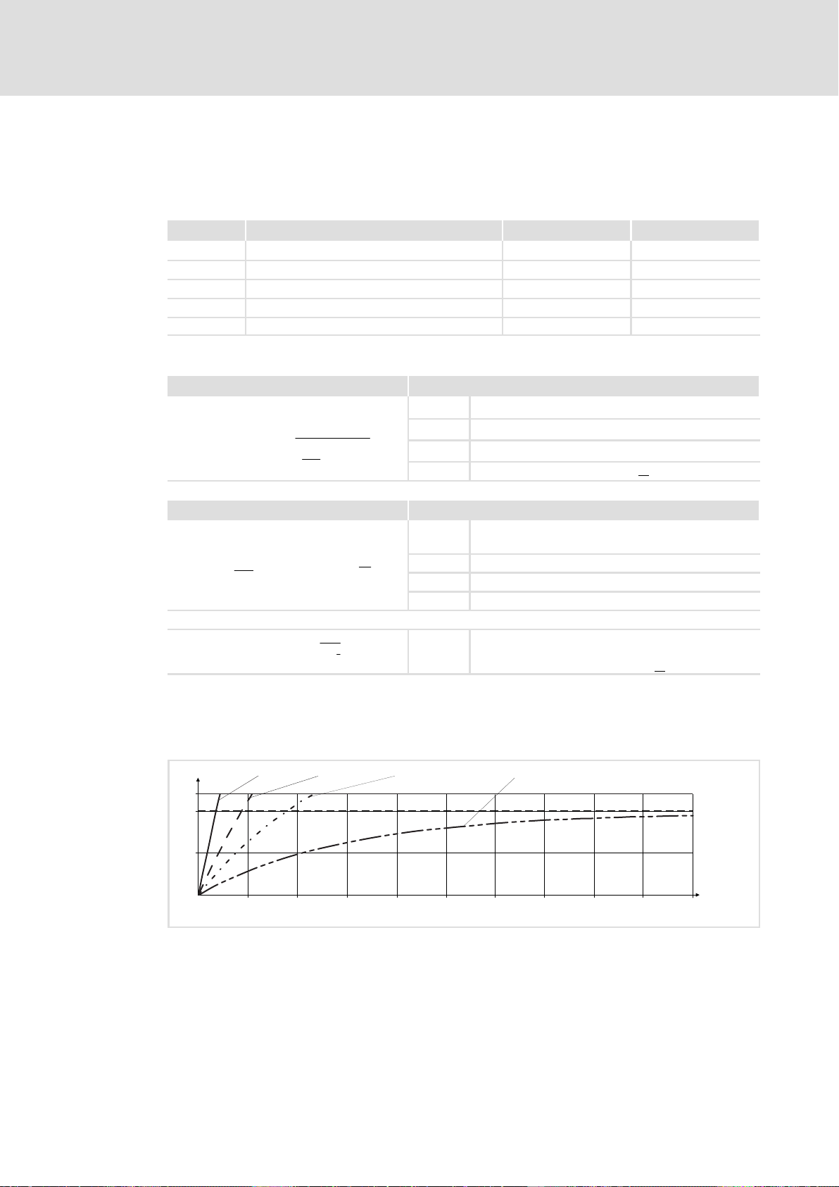
Read release time in the diagram
Diagram for detecting the release times for a motor with a thermal motor time constant
of 5 minutes (Lenze setting C0128):
L [%]
120
100
50
0
Fig. 2−1 I2 × t−monitoring: Release times for different motor currents and trigger thresholds
I = 3 × I
Mot N
0 100 200 300 400 500 600 700 800 900
I
Mot
I
r
LI
T Time
I = 2 × I
Mot N
Actual motor current (C0054)
Rated motor current (C0088)
2
x t load of the motor (display: C0066)
I = 1.5 × I
Mot N
I = 1 × I
Mot N
t [s]
1000
9300STD105
EDBCSXM064 EN 11.0
23
Page 24
2
Safety instructions
Thermal motor monitoring
Self−ventilated motors
2.2.2 Self−ventilated motors
Due to the construction, self−ventilated standard motors are exposed to an increased heat
generation in the lower speed range compared to forced ventilated motors.
Warnings!
For complying with the UL 508C standard, you have to set the
speed−dependent evaluation of the permissible torque via code C0129/x.
Parameter setting
The following codes can be set for I
Code Meaning Value range Lenze setting
C0066 Display of the I2 x t load of the motor 0 ... 250 % −
C0120 Threshold: Triggering of error "OC6" 0 ... 120 % 0 %
C0127 Threshold: Triggering of error "OC8" 0 ... 120 % 0 %
C0128 Thermal motor time constant 0.1 ... 50.0 min 5.0 min
C0606 Response to error "OC8" TRIP, warning, off Warning
C0129/1 S1 torque characteristic I1/I
C0129/2 S1 torque characteristics n2/n
2
x t monitoring:
rated
rated
10 ... 200 % 100 %
10 ... 200 % 40 %
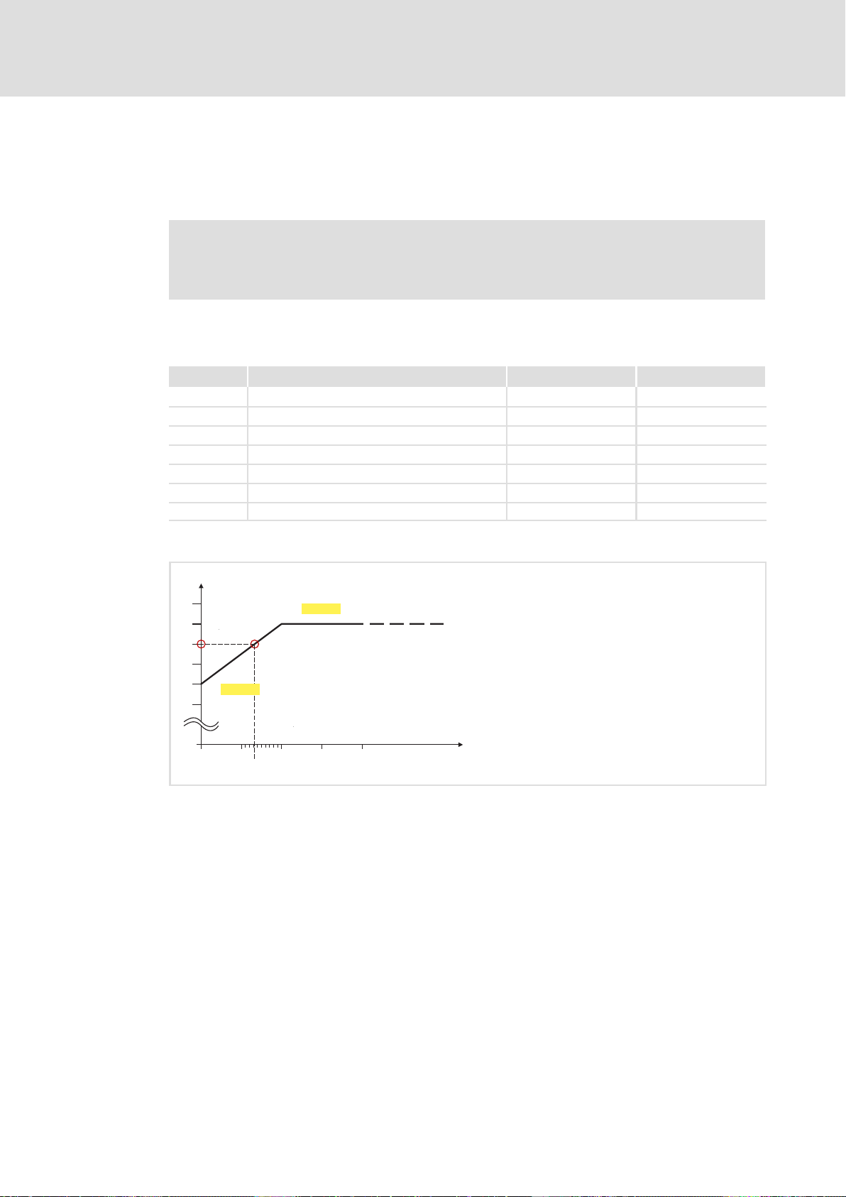
Effect of code C0129/x
I / I
N
1.1
1.0
3
0.9
0.8
0.7
0.6
Fig. 2−2 Working point in the range of characteristic lowering
0
0
0 0.1
C0129/1
0.132
C0129/2
1
2
0.2 0.3 0.4
n / n
N
9300STD350
The lowered speed / torque characteristic (Fig. 2−2) reduces the permissible thermal load
of self−ventilated standard motors. The characteristic is a line the definition of which
requires two points:
ƒ Point : Definition with C0129/1
This value also enables an increase of the maximally permissible load.
ƒ Point : Definition with C0129/2
With increasing speeds, the maximally permissible load remains unchanged
(I
Mot
= I
rated
).
In Fig. 2−2, the motor speed and the corresponding permissible motor torque () can be
read for each working point (on the characteristic () ... ). can also be calculated
using the values in C0129/1and C0129/2 (evaluation coefficient "y", 25)
24
EDBCSXM064 EN 11.0
Page 25
Thermal motor monitoring
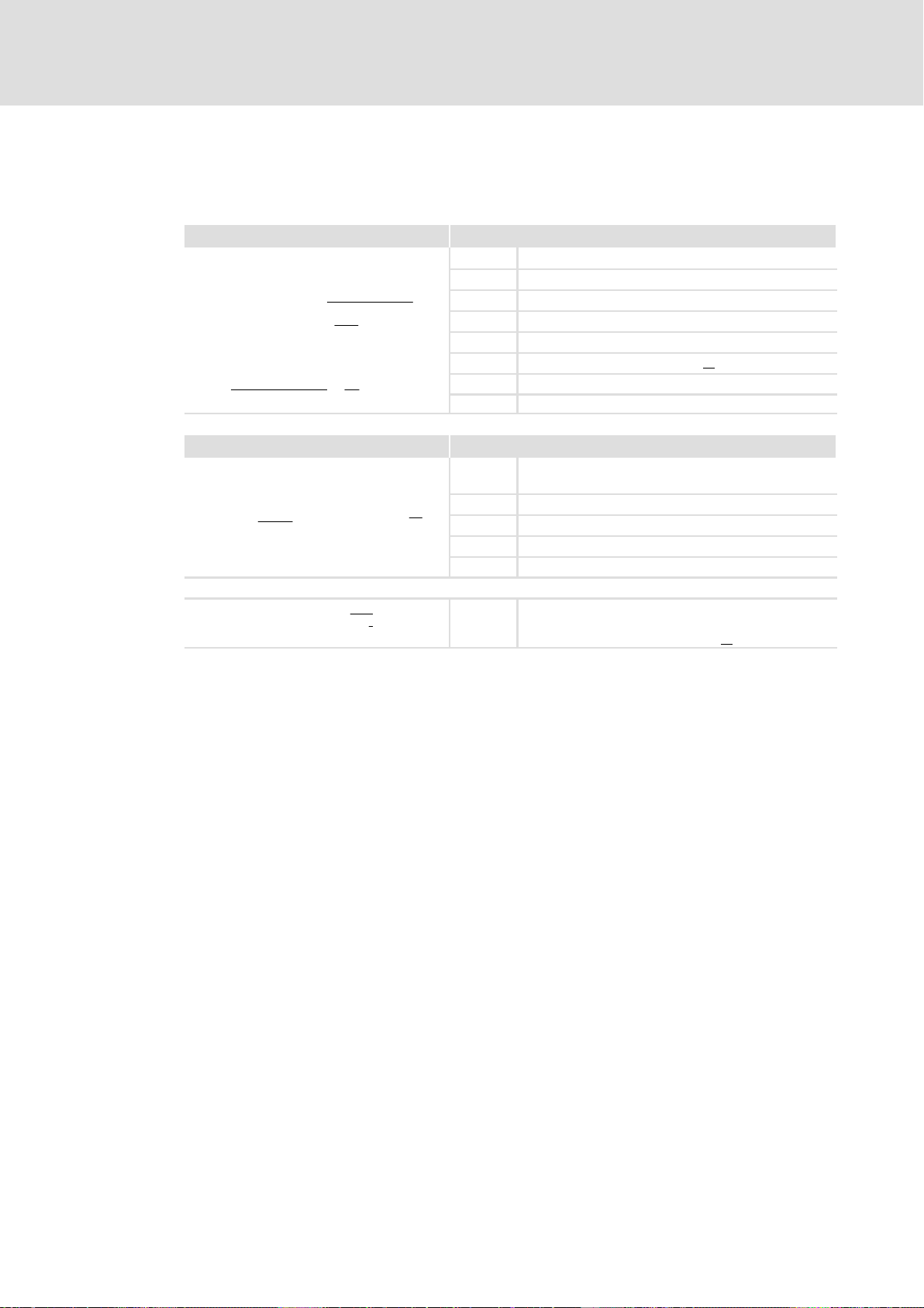
Calculate release time and I2 x t load
Calculate the release time and the I
2
x t load of the motor considering the values in
C0129/1 and C0129/2(evaluation coefficient "y").
Formulae for release time Information
T Release time of the I2 x t monitoring
ȡ
I
Mot
ǒ
y I
n
Ǹ
e
z ) 1
Ǔ
N
n
) C0129ń1
N
*
T +*(t) ln
ȧ
ȧ
1 *
Ȣ
100% * C0129ń1
y +
Formulae for I2 x t load Information
If the controller is inhibited, the I2 x t load is reduced:
L(t) +
C0129ń2
I
Mot
ǒ
y I
L(t) + L
2
Ǔ
100% ǒ1 * e
N
Start
2
100
t
t
ȣ
t Thermal motor time constant (C0128)
In Function: Natural logarithm
ȧ
ȧ
I
Mot
Ȥ
I
r
z Threshold value in C0120 (OC6) or C0127 (OC8)
y Evaluation coefficient
n
rated
L(t) Chronological sequence of the I2 x t load of the motor
y Evaluation coefficient
*t
Ǔ
t
I
Mot
Ir Rated motor current (C0088)
t Thermal motor time constant (C0128)
L
Start
Actual motor current (C0054)
Rated motor current (C0088)
Rated speed (C0087)
(Display: C0066)
Actual motor current (C0054)
I2 x t load before controller inhibit
If an error is triggered, the value corresponds to the
threshold value set in C0120 (OC6) or
Safety instructions
Self−ventilated motors
C0127 (OC8).
2
EDBCSXM064 EN 11.0
25
Page 26

2
2.3 Residual hazards
Safety instructions
Residual hazards
Protection of persons
ƒ Before working on the axis module, check that no voltage is applied to the power
terminals, because
– the power terminals +UG, −UG, U, V and W remain live for at least 3 minutes after
mains switch−off.
– the power terminals +UG, −UG, U, V and W remain live when the motor is stopped.
ƒ The heatsink has an operating temperature of > 70 °C:
– Direct skin contact with the heatsink results in burns.
ƒ The discharge current to PE is > 3.5 mA AC or. > 10 mA DC.
– EN 61800−5−1 requires a fixed installation.
– The PE connection must comply with EN 61800−5−1.
– Comply with the further requirements of EN 61800−5−1 for high discharge
currents!
Device protection
ƒ All pluggable connection terminals must only be connected or disconnected when
no voltage is applied!
ƒ The power terminals +UG, −UG, U, V, W and PE are not protected against polarity
reversal.
– When wiring, observe the polarity of the power terminals!
ƒ Power must not be converted until all devices of the power system are ready for
operation. Otherwise, the input current limitation may be destroyed.
Frequent mains switching (e.g. inching mode via mains contactor) can overload and
destroy the input current limitation of the axis module, if
ƒ the axis module is supplied via the ECSxE supply module and the input current
limitation is activated depending on the DC−bus voltage (C0175 = 1 or 2).
ƒ the axis module is not supplied via a supply module delivered by Lenze.
ƒ the low−voltage supply (24 V) is switched off.
For this reason allow a break of at least three minutes between two starting operations!
Use the safety function ˜Safe torque off˜ (STO) for frequent disconnections for safety
reasons.
26
EDBCSXM064 EN 11.0
Page 27

Safety instructions
Residual hazards
Motor protection
ƒ Only use motors with a minimum insulation resistance of û = 1.5 kV,
min. du/dt = 5 kV/ms.
– Lenze motors meet these requirements.
ƒ When using motors with an unknown insulation resistance, please contact your
motor supplier.
ƒ Some settings of the axis module lead to an overheating of the connected motor,
e.g. longer operation of self−ventilated motors with low speeds.
ƒ Use PTC thermistors or thermostats with PTC characteristic for motor temperature
monitoring.
2
EDBCSXM064 EN 11.0
27
Page 28

2
Safety instructions
Safety instructions for the installation according to UL
2.4 Safety instructions for the installation according to UL
Warnings!
General markings:
ƒ Use 60/75 °C or 75 °C copper wire only.
ƒ Maximum ambient temperature 55 °C, with reduced output current.
Markings provided for the supply units:
ƒ Suitable for use on a circuit capable of delivering not more than 5000 rms
symmetrical amperes, 480 V max, when protected by K5 or H Fuses
(400/480 V devices).
ƒ Alternate − Circuit breakers (either inverse−time, instantaneous trip types or
combination motor controller type E) may be used in lieu of above fuses
when it is shown that the let−through energy (i
) of the inverse−time current−limiting circuit breaker will be less
p
current (I
than that of the non−semiconductor type K5 fuses with which the drive has
been tested.
ƒ Alternate − An inverse−time circuit breaker may be used, sized upon the
input rating of the drive, multiplied by 300 %.
Markings provided for the inverter units:
ƒ The inverter units shall be used with supply units which are provided with
overvoltage devices or systems in accordance with UL840 2nd ed., Table 5.1.
ƒ The devices are provided with integral overload and integral thermal
protection for the motor.
ƒ The devices are not provided with overspeed protection.
2
t) and peak let−through
Terminal tightening torque of lb−in (Nm)
Terminal lb−in Nm
X 21, X 22, X 23, X 24 10.6 ... 13.3 1.2 ... 1.5
X4, X6, X14 1.95 ... 2.2 0.22 ... 0.25
X 25 4.4 ... 7.1 0.5 ... 0.8
Wiring diagram AWG
Terminal AWG
X 21, X 22, X 23, X 24 12 ... 8
X4, X6, X14 28 ... 16
X 25 24 ... 12
28
EDBCSXM064 EN 11.0
Page 29

2.5 Notes used
The following pictographs and signal words are used in this documentation to indicate
dangers and important information:
Safety instructions
Structure of safety instructions:
Danger!
(characterises the type and severity of danger)
Note
(describes the danger and gives information about how to prevent dangerous
situations)
Pictograph and signal word Meaning
Danger!
Danger!
Stop!
Safety instructions
Notes used
Danger of personal injury through dangerous electrical voltage.
Reference to an imminent danger that may result in death or
serious personal injury if the corresponding measures are not
taken.
Danger of personal injury through a general source of danger.
Reference to an imminent danger that may result in death or
serious personal injury if the corresponding measures are not
taken.
Danger of property damage.
Reference to a possible danger that may result in property
damage if the corresponding measures are not taken.
2
Application notes
Pictograph and signal word Meaning
Note!
Tip!
Special safety instructions and application notes for UL and UR
Pictograph and signal word Meaning
Warnings!
Warnings!
Important note to ensure troublefree operation
Useful tip for simple handling
Reference to another documentation
Safety or application note for the operation of a UL−approved
device in UL−approved systems.
Possibly the drive system is not operated in compliance with UL
if the corresponding measures are not taken.
Safety or application note for the operation of a UR−approved
device in UL−approved systems.
Possibly the drive system is not operated in compliance with UL
if the corresponding measures are not taken.
EDBCSXM064 EN 11.0
29
Page 30

3
Technical data
General data and operating conditions
3 Technical data
3.1 General data and operating conditions
Standards and operating conditions
Conformity CE Low−Voltage Directive (2006/95/EG)
Approvals
Max. permissible
Motor cable length
Packaging (EN ISO 4180) Shipping package
Installation l Installation into IP20 control cabinet
Mounting position vertically suspended
Free space
shielded 50 m For rated mains voltage and switching frequency of 8 kHz
above ³ 65 mm
below ³ 65 mm
to the sides can be mounted directly side by side without any clearance
UL 508C
CSA 22.2 No. 14
l For the "safe torque off" function (formerly "safe standstill"): mounting in IP54
control cabinet
With ECSZS000X0B shield mounting kit: > 195 mm
Power Conversion Equipment
Underwriter Laboratories (File No. E132659)
for USA and Canada
Environmental conditions
Climate 3k3 in accordance with IEC/EN 60721−3−3
Condensation, splash water and ice formation
not permissible.
Site altitude 0 ... 4000 m amsl
Pollution EN 61800−5−1, UL840: Degree of pollution 2
Vibration resistance Acceleration resistant up to 0.7 g (Germanischer Lloyd, general conditions)
Storage IEC/EN 60721−3−1 1K3 (−25 ... + 55 °C)
Transport IEC/EN 60721−3−2 2K3 (−25 ... +70 °C)
Operation IEC/EN 60721−3−3 3K3 (0 ... + 55 °C)
l Atmospheric pressure: 86 ... 106 kPa
l Above +40 °C: reduce the rated output
current by 2 %/°C.
l Reduce rated output current by
5 %/1000 m above 1000 m amsl.
l Over 2000 m amsl: Use is only permitted in
environments with overvoltage category II
30
EDBCSXM064 EN 11.0
Page 31

Technical data
General data and operating conditions
General electrical data
EMC Compliance with the requirements acc. to EN 61800−3
Noise emission Compliance with the limit class C2 acc. to EN 61800−3
(achieved by using collective filters typical for the application)
Noise immunity
Insulation resistance EN61800−5−1, UL840: Overvoltage category III
Discharge current to PE
(Acc. to EN 61800−5−1)
Enclosure IP20 for
Protective measures against l Short circuit in power terminals
Protective insulation of control circuits Protective separation from the mains
1)
Noise immunity in the above−mentioned severities must be guaranteed by the control cabinet! The user
must check the compliance with the severities!
Requirements acc. to EN 61800−3
Requirement Standard Severity
1)
ESD
Conducted high frequency EN 61000−4−6 10 V; 0.15 ... 80 MHz
RF interference (housing) EN 61000−4−3 3, i. e. 10 V/m;
Burst EN 61000−4−4 3/4, i. e. 2 kV/5 kHz
Surge (surge voltage on mains
cable)
> 3.5 mA AC
l Standard installation (built−in unit)
l Cold−plate technique
l Mounting with thermal separation (push−through technique), IP54 on heatsink side
– Motor terminal has a limited protection against short circuit (after short circuit
detection, the error message must be reset.)
l Short circuit in auxiliary circuits
– Digital outputs: Short−circuit−proof
– Bus and encoder systems: Limited protection against short circuit (if necessary,
monitoring functions can be switched off, in this case, error messages must be
reset:)
l Earth fault (earth−fault protected during operation, limited earth−fault protection
on mains power−up)
l Overvoltage
l Motor stalling
l Motor overtemperature (input for KTY, I
Double/reinforced insulation acc. to EN 61800−5−1
EN 61000−4−2 3, i. e.
EN 61000−4−5 3, i. e. 1.2/50 ms
2
x t monitoring)
3
l 8 kV for air discharge
l 6 kV for contact discharge
80 ... 1000 MHz
l 1 kV phase/phase
l 2 kV phase/PE
EDBCSXM064 EN 11.0
31
Page 32

3
Technical data
Rated data
3.2 Rated data
Rated data Type
ECSx004 ECSx008 ECSx016
Output power 400 V mains S
Data for operation with upstream power supply module
on mains voltage
DC−bus voltage V
DC−bus current I
Rated output current at 4 kHz
(causes a heatsink temperature of 70°C at an ambient
temperature of 20°C)
Rated output current at 8 kHz (at an ambient
temperature of 20°C it causes a heatsink temperature
of 70°C)
Max. output current
(acceleration current)
Continuous current at standstill
(holding current at 90°C, 4 kHz)
Short−time standstill current
(holding current at 90 °C, 4 kHz)
Short−time standstill current
(holding current at 70 °C, 4 kHz)
Short−time standstill current
(holding current at 70 °C, 8 kHz)
Power loss (operation with rated
current at 4 kHz / 8 kHz)
Max. output frequency f
Mass m [kg] approx. 2.4
1)
2)
2)
2)
Total
Inside the device 13.3 17.3 20.7
Heatsink 14.0 29.0 64.0
1)
If the heatsink temperature reaches 70°C, the switching frequency automatically changes to 4 kHz.
2)
The indicated temperature is the measured heatsink temperature (C0061).
Application software:
[kVA] 1.3 2.6 5.3
rated
V
[V] 400 480 400 480 400 480
mains
[V] 15 ... 770
DC−bus
[A] 2.5 2.0 4.9 3.9 9.8 7.8
DC−bus
Ir [A] 2.0 1.6 4.0 3.2 8.0 6.4
Ir [A] 1.4 1.1 2.7 2.2 5.3 4.2
I
[A] 4.0 8.0 16.0
max
I
0,eff 4 kHz
I
0,eff 4 kHz
I
0,eff 4 kHz
I
0,eff 8 kHz
S = Speed & Torque P = Posi & Shaft
M = Motion A = Application
[A] 2.0 1.6 4.0 3.2 8.0 6.4
[A] 2.3 4.6 9.1
[A] 3.0 6.0 12.0
[A] 1.5 3.0 6.0
27.3 46.3 84.7
P
[W]
loss
[Hz] 600
out
Axis module
32
EDBCSXM064 EN 11.0
Page 33

Technical data
Rated data
3
Rated data Type
ECSx032 ECSx048 ECSx064
Output power 400 V mains S
Data for operation with upstream power supply module
on mains voltage
DC−bus voltage V
DC−bus current I
Rated output current at 4 kHz
(causes a heatsink temperature of 70°C at an ambient
temperature of 20°C)
Rated output current at 8 kHz (at an ambient
temperature of 20°C it causes a heatsink temperature
of 70°C)
Max. output current
(acceleration current)
Continuous current at standstill
(holding current at 90°C, 4 kHz)
Short−time standstill current
(holding current at 90 °C, 4 kHz)
Short−time standstill current
(holding current at 70 °C, 4 kHz)
Short−time standstill current
(holding current at 70 °C, 8 kHz)
Power loss (operation with rated
current at 4 kHz / 8 kHz)
Max. output frequency f
Mass m [kg] approx. 2.4 approx. 3.3
1)
2)
2)
2)
2)
Total
Inside the device 27.5 34.5 41.0
Heatsink 117.0 132.0 158.0
1)
If the heatsink temperature reaches 70°C, the switching frequency automatically changes to 4 kHz.
2)
The indicated temperature is the measured heatsink temperature (C0061).
Application software:
[kVA] 8.3 11.2 13.2
rated
U
[V] 400 480 400 480 400 480
mains
[V] 15 ... 770
DC−bus
[A] 15.6 12.5 20.9 16.8 24.5 19.6
DC−bus
Ir [A] 12.7 10.2 17.0 13.6 20.0 16.0
Ir [A] 8.5 6.8 11.3 9.0 13.3 10.6
I
[A] 32.0 48.0 64.0
max
I
0,eff 4 kHz
I
0,eff 4 kHz
I
0,eff 4 kHz
I
0,eff 8 kHz
S = Speed & Torque P = Posi & Shaft
M = Motion A = Application
[A] 16.0 12.8 23.0 18.4 27.0 21.6
[A] 18.1 27.2 36.3
[A] 24.0 36.0 48.0
[A] 12.1 18.1 24.2
144.5 166.5 199.0
P
[W]
loss
[Hz] 600
out
Axis module
EDBCSXM064 EN 11.0
33
Page 34

3
Technical data
Current characteristics
Increased continuous current depending on the control factor
3.3 Current characteristics
3.3.1 Increased continuous current depending on the control factor
In the lower speed range ˘ the motor does not need the full motor voltage ˘ particularly
the more powerful ECS axis modules can be permanently operated with increased output
current (cp. continuous current I
I [A]
I [A]
0
30.0
27.0
25.0
23.0
20.0
16.0
15.0
10.0
8.0
5.0
4.0
2.0
0.0
0 % 50 %
Fig. 3−1 Continuous device current, depending on the output voltage for U
I
r
U
Mot_n
U
Mot_max
Rated output current of the axis module
Actual controller output voltage
0.9 x current mains voltage
32).
0,eff
ECSxS/P/M/A064
ECSxS/P/M/A048
ECSxS/P/M/A032
ECSxS/P/M/A016
ECSxS/P/M/A008
ECSxS/P/M/A004
I [A]
N
20.0
17.0
12.7
U/U
Mot
£ 400 V at 4 kHz
mains
8.0
4.0
2.0
100 %
max
ECSXA002
The permissible continuous current depends on the control factor of the power output
stages, approximately on the ratio of the motor voltage output in the operating point
(U
the components involved at rated load and a control margin, U
) to the maximum possible output voltage (U
Mot_n
Mot_max
). Due to voltage drops across
Mot_max
can be estimated
with 90 % of the mains voltage.
Tip!
The operating threshold of the device utilisation monitoring (I x t) function is
automatically adapted to the continuous device current which changes
depending on the output voltage (see fig.).
34
EDBCSXM064 EN 11.0
Page 35

Technical data
Current characteristics
Increased continuous current depending on the control factor
The following table shows the connections between mains voltage, DC−bus voltage and
motor voltage:
3
Mains voltage
]
[U
mains
3 x 230 V AC 310 V DC 3 x 205 V AC
3 x 380 V AC 510 V DC 3 x 340 V AC
3 x 400 V AC 540 V DC 3 x 360 V AC
3 x 415 V AC 560 V DC 3 x 370 V AC
3 x 460 V AC 620 V DC 3 x 415 V AC
3 x 480 V AC 650 V DC 3 x 435 V AC
3 x 528 V AC 712 V DC 3 x 475 V AC
DC−bus voltage
= U
[U
DC
mains
x 1.35]
Output voltage (motor voltage)
nominally achievable for 100 %
modulation
[U
mot
= 0.66 x UDC]
For steady−state operation in generator mode with increased DC−bus voltage or supply
from a closed−loop DC−voltage source, interpolate accordingly between the values given in
the table.
The increased rated currents are valid for the entire voltage range specified at switching
frequencies of 4 kHz and 8 kHz.
Note!
If in this connection a heatsink temperature of > 70 °C is reached, the drive
switches to a switching frequency of 4 kHz, independently of the selected
switching frequency.
EDBCSXM064 EN 11.0
35
Page 36

3
Technical data
Current characteristics
Increased continuous current depending on the control factor
Example:
The ECS axis module suitable for operation in conjunction with a Lenze motor of type
MCS 14L32 is to be determined.
ƒ Rated motor data
– Rated motor torque (M
– Rated motor speed (n
– Motor voltage at 3250 rpm (U
– Rated motor current (I
– Max. motor current (I
ƒ Application data:
– Max. torque (M
) = 35 Nm
max
– Max. operating speed (n
– An effective process power (P
– The drive rating results in an effective motor current (I
) = 17.2 Nm
mot
) = 3225 rpm
mot
) = 15 A
mot
mot_max
) = 2500 rpm
max
mot_n3250
) = 275 V
) = 92 A
) of 4.5 kW arises on the basis of the Mn diagram.
eff
Mot_eff
) of 14.8 A.
A first estimation based on the rated current of the ECS axis module would probably lead
to selecting the ECSxM048 module with a rated current of 17.0 A.
However, if we take into account the increased continuous current for smaller control
factors, the more cost−effective ECSxM032 axis module with a rated current of 12.7 A can
be used here.
ƒ When the MCS 14L32 is operated with 2500 rpm, the real motor voltage is
(U
Mot_n2500
U
ƒ This leads to the following max. control factor (α
):
Mot_n2500
a
max
+ U
+
Mot_n3250
U
Mot_n2500
U
max
n
max
@
n
Mot
Þ
Þ
275V @
max
2500rpm
3250rpm
+ 212V
) of the axis module:
212V
360V
+ 0.59 + 59%
Using the current characteristic of Fig. 3−1 ( 34), a continuous current of 15.5 A can
be determined for the ECSxM032 axis module when the control factor (α
ƒ Result:
) is 59 %.
max
Under the conditions mentioned above the MCS 14L32 Lenze motor can be operated
continuously on the ECSxM032 axis module.
36
EDBCSXM064 EN 11.0
Page 37

3.3.2 Device protection by current derating
The maximum output current is limited. With output frequencies < 5 Hz the limitation
depends on the heatsink temperature.
Technical data
Current characteristics
Device protection by current derating
3
1.00
Iout
Imax
0.75
0.57
0.38
0.00
Fig. 3−2 Current derating characteristics
≤ 70 °C
90 °C
0510
Operation with switching frequency = 8 kHz (C0018 = 1).
l If the current exceeds the characteristic , the switching frequency is automatically
changed to 4 kHz (e.g. for higher torque in acceleration processes).
Operation with switching frequency = 4 kHz (C0018 = 0).
l The current limitation follows the characteristic .
l With output frequencies < 5 Hz and heatsink temperatures between 70 and 90 °C the
current limit is steplessly adjusted in the range .
1.00
0.67
fout [Hz]
ECSXA024
Type
Switching frequency 8 kHz Switching frequency 4 kHz
f
> 5 Hz f
out
ECSxM004 2.7 1.5 4.0 3.0 2.3
ECSxM008 5.3 3.0 8.0 6.0 4.6
ECSxM016 10.7 6.0 16.0 12.0 9.1
ECSxM032 21.3 12.1 32.0 24.0 18.1
ECSxM048 32.0 18.1 48.0 36.3 27.2
ECSxM064 42.7 24.2 64.0 48.0 36.3
0 Hz f
out
I
[A]
max
> 5 Hz f
out
0 Hz
out
£ 70 °C
f
out
0 Hz
90 °C
EDBCSXM064 EN 11.0
37
Page 38

4
Mechanical installation
Important notes
4 Mechanical installation
4.1 Important notes
ƒ Axis modules of the ECS series provide IP20 enclosure and can therefore only be
used for installation in control cabinets.
ƒ If the cooling air contains air pollutants (dust, fluff, grease, aggressive gases):
– Take suitable preventive measures , e.g. separate air duct, installation of filters,
regular cleaning.
ƒ Possible mounting positions:
– Vertical at the mounting plate
– DC bus connections (X23) at the top
– Motor connection (X24) at the bottom
ƒ Maintain the specified clearances (above and below) to other installations!
– If the ECSZS000X0B shield mounting kit is used, an additional clearance is
required.
– Ensure unimpeded ventilation of cooling air and outlet of exhaust air.
– Several modules of the ECS series can be installed in the control cabinet next to
each other without any clearance.
ƒ The mounting plate of the control cabinet
– must be electrically conductive.
– must not be varnished.
ƒ In case of continuous vibrations or shocks use shock absorbers.
38
EDBCSXM064 EN 11.0
Page 39

Mechanical installation
Mounting with fixing rails (standard installation)
4.2 Mounting with fixing rails (standard installation)
4.2.1 Dimensions
Note!
Mounting with ECSZS000X0B shield mounting kit:
ƒ Mounting clearance below the module > 195 mm
4
Dimensions
0
g
³ 65 mm
³ 65 mm
Fig. 4−1 Dimensions for "panel−mounted" design
Axis module Dimensions [mm]
Type Size a b d d1 e h g
ECSE004
ECSE008
ECSE016
ECSE032
ECSE048
ECSE064
1)
Max. 212 mm, depending on the plugged−on communication module
e
131
88,5
240 276 260
h
d
d1
a
b
g
h
d
d1
176
212
1
g
g
a
1)
10
b
ECSxA005
6,5
(M6)
EDBCSXM064 EN 11.0
Application software: S = Speed & Torque P = Posi & Shaft
M = Motion A = Application
39
Page 40

4
4.2.2 Mounting steps
Mechanical installation
Mounting with fixing rails (standard installation)
Mounting steps
How to install the axis module:
1. Prepare the fixing holes on the mounting surface.
– Use the drilling jig for this purpose.
2. Take the fixing rails from the accessory kit in the cardboard box.
3. Push the rails into the slots of the heatsink:
– From above: Push in the long side.
– From below: Push in the short side.
4. Attach the axis module to the mounting surface.
40
EDBCSXM064 EN 11.0
Page 41

Mechanical installation
Mounting with thermal separation (push−through technique)
4.3 Mounting with thermal separation (push−through technique)
For the push−through technique the rear panel of the control cabinet must be a steel plate
with a thickness of at least 2 mm.
The edges of the mounting cutout and the fixing holes for the clamps must be slightly
curved inwards (towards the axis module).
Cooling
With the separated heatsink the heat generation in the control cabinet can be reduced.
ƒ Distribution of the power loss:
– approx. 65 % via separated cooler
– approx. 35 % in the inside of the axis module
ƒ Protection class of the separated cooler: IP54
– The sealing surface at the heatsink of the axis module must rest completely
against the mounting plate.
– Use a liquid thread sealant to bond the screws of the clamps.
4
ƒ For sufficient cooling of the drive system:
– Air flow behind the rear panel of the control cabinet must be ³ 3 m/s (e.g. by
means of a collective fan).
ƒ With sufficient cooling, the rated data of the axis modules remain valid.
EDBCSXM064 EN 11.0
41
Page 42

4
Mechanical installation
Mounting with thermal separation (push−through technique)
Dimensions
4.3.1 Dimensions
Note!
Mounting with ECSZS000X0B shield mounting kit:
ƒ Mounting clearance below the module > 195 mm
³ 65 mm
³ 65 mm
0
a1
g
b1
b
e
e1
c1
a
Z
h
d
g
b1
b
1
a1
g
c1
a
Z
h
d
g
Fig. 4−2 Dimensions for "push−through design"
Z Mounting cutout (a1 x b1), 43
Axis module Dimensions [mm]
Type Size a a1 b b1 c1 d e e1 g h
ECSD004
ECSD008
ECSD016
ECSD032
ECSD048
ECSD064
1)
Max. 145 mm, depending on the plugged−on communication module
Application software: S = Speed & Torque P = Posi & Shaft
131 121,5
88,5 78,5
240 197 75 250
M = Motion A = Application
109
145
1)
67 M5 10,5
ECSXA007
42
EDBCSXM064 EN 11.0
Page 43

Mounting with thermal separation (push−through technique)
Dimensions of mounting cutout
Note!
Installation with shield mounting ECSZS000X0B:
ƒ Clearance below the mounting cutout > 220 mm
Mechanical installation
a1 a1
4
Dimensions
g
³ 70 mm
b1
g
³ 90 mm
c1
0
Fig. 4−3 Dimensions of mounting cutout
Mounting surface
Mounting cutout for size
Mounting cutout for size
Axis module Dimensions [mm]
Type Size a1 b1 c1 d g h
ECSD004
ECSD008
ECSD016
ECSD032
ECSD048
ECSD064
121,5
78,5
197 75 250 M5 10,5
1
c1
h
2
b1
d
ECSXA063
EDBCSXM064 EN 11.0
Application software: S = Speed & Torque P = Posi & Shaft
M = Motion A = Application
43
Page 44

4
Mechanical installation
Mounting with thermal separation (push−through technique)
Mounting steps
4.3.2 Mounting steps
How to mount the axis module:
1. Prepare the fixing holes for the wire clamps on the mounting area.
For this purpose, apply a drilling jig.
2. Prepare the mounting cutout.
The edges of the mounting cutout and the fixing holes for the wire clamps have to be
slightly arched inwardly (to the axis module).
3. Apply liquid thread sealant to the threads of the screws for the wire clamps.
4. Fix the wire clamps together with the functional earth conductor supplied (Fig. 4−4).
The functional earth conductor is part of the scope of supply of the ECSDx... axis module
5. Push the axis module into the mounting cutout.
6. Engage axis module in the wire clamp at the top and the bottom.
7. Connect the functional earth conductor to the axis module (Fig. 4−4).
Note!
Fixing the functional earth conductor to the ECSDx... axis module is required
for a better electromagnetic compatibility (EMC).
ECSXA081
Fig. 4−4 Functional earth conductor at the ECSDx... axis module
Functional earth conductor
44
EDBCSXM064 EN 11.0
Page 45

4.4 Mounting in cold−plate design
The axis modules ECSC... are intended for mounting in cold−plate design (e.g. on collective
coolers).
Requirements for collective coolers
The following requirements must be met to ensure a safe operation of the axis modules:
ƒ Good thermal contact with the cooler
– The contact surface between collective cooler and axis module must be at least as
large as the cooling plate of the axis module.
– Smooth contact surface, max. deviation 0.05 mm.
– Connect the collective cooler with all specified screwed connections to the axis
module.
Mechanical installation
Mounting in cold−plate design
4
ƒ Maintain the thermal resistance R
according to the table.
th
– The values apply for operating the axis modules under rated conditions.
Axis module Power to be dissipated Heat sink − environment
Type Ploss [W] Rth [k/W]
ECSC004 14.0
ECSC008 29.0
ECSC016 64.0
ECSC032 117.0
ECSC048 132.0
ECSC064 158.0 0,11
Application software: S = Speed & Torque P = Posi & Shaft
M = Motion A = Application
ƒ Ambient conditions:
0,31
0,13
– Furthermore the rated data regarding the ambient temperature and the derating
factors at increased temperature apply to the axis modules ( 30 et seqq.).
– Temperature of the cooling plate ("Cold Plate"): max. +85 °C
EDBCSXM064 EN 11.0
45
Page 46

4
Mechanical installation
Mounting in cold−plate design
Dimensions
4.4.1 Dimensions
Note!
Mounting with ECSZS000X0B shield mounting kit:
ƒ Mounting clearance below the module > 195 mm
³ 65 mm
0
a
g
d
b
a1
g
b
1
a
a1
³ 65 mm
Fig. 4−5 Dimensions for "cold−plate design"
Axis module Dimensions [mm]
Type Size a a1 b c1 d e g
ECSC004
ECSC008
ECSC016
ECSC032
ECSC048
ECSC064
1)
Max. 157 mm, depending on the plugged−on communication module
Application software: S = Speed & Torque P = Posi & Shaft
e
131 90
88,5 60
M = Motion A = Application
282 50 287
g
c1
121
157
g
c1
1)
ECSXA009
M6
46
EDBCSXM064 EN 11.0
Page 47

Mechanical installation
Mounting in cold−plate design
Mounting steps
4
4.4.2 Mounting steps
Fig. 4−6 Mounting for "cold−plate design"
Proceed as follows to mount the axis module:
1. Prepare the fixing holes on the mounting plate.
– Use a drilling jig for this purpose.
À Á Â
ECSXA030
2. Clean and degrease the contact area of collective cooler and heatsink of the
axis module (e.g. with methylated spirit).
3. Screw the support onto the collective cooler.
4. Insert the axis module from above into the support and fasten the two stud
bolts with 3.5 ... 4.5 Nm .
Note!
Penetration depth of the screws into the collective cooler: approx. 15 mm!
Tip!
The heat transfer resistance is reduced if − following step 2. −
ƒ a thin layer of heat conducting paste is applied to the contact surface or
ƒ heat conducting foil is used.
EDBCSXM064 EN 11.0
47
Page 48

5
Electrical installation
Installation according to EMC (installation of a CE−typical drive system)
5 Electrical installation
5.1 Installation according to EMC (installation of a CE−typical drive system)
General information
ƒ The electromagnetic compatibility of a machine depends on the type of installation
and care taken.Especially consider the following:
– Assembly
– Filtering
– Shielding
– Earthing
ƒ For diverging installations, the evaluation of the conformity to the EMC Directive
requires a check of the machine or system regarding the EMC limit values. This for
instance applies to:
– Use of unshielded cables
– Use of collective interference filters instead of the assigned RFI filters
– Operating without RFI filters
ƒ The compliance of the machine application with the EMC Directive is in the
responsibility of the user.
– If you observe the following measures, you can assume that the machine will
operate without any EMC problems caused by the drive system, and that
compliance with the EMC Directive and the EMC law is achieved.
– If devices which do not comply with the CE requirement concerning noise
immunity EN 61000−6−2 are operated close to the ECS modules, these devices may
be electromagnetically affected by the ECS modules.
48
EDBCSXM064 EN 11.0
Page 49

Electrical installation
Installation according to EMC (installation of a CE−typical drive system)
Assembly
ƒ Connect the ECS modules, RFI filters, and mains choke to the earthed mounting
plate with a surface as large as possible:
– Mounting plates with conductive surfaces (zinc−coated or stainless steel) allow for
permanent contact.
– Painted plates are not suitable for an EMC−compliant installation.
ƒ If you use the ECSxK... capacitor module:
– Install the capacitor module between the power supply module and the axis
module(s).
– If the total cable length in the DC−bus connection is > 5 m, install the capacitor
module as close as possible to the axis module with the greatest power.
ƒ If you use several mounting plates:
– Connect as much surface of the mounting plates as possible (e.g. with copper
bands).
ƒ Ensure the separation of the motor cable and the signal or mains cables.
5
ƒ Avoid a common terminal/power strip for the mains input and motor output.
ƒ Lay the cables as close as possible to the reference potential. Freely suspended
cables act like aerials.
Filters
Only use RFI filters and mains chokes which are assigned to the power supply modules:
ƒ RFI filters reduce impermissible high−frequency interferences to a permissible value.
ƒ Mains chokes reduce low−frequency interferences which in particular depend on the
motor cables and their lengths.
EDBCSXM064 EN 11.0
49
Page 50

5
Electrical installation
Installation according to EMC (installation of a CE−typical drive system)
Shielding
ƒ Connect the motor cable shield to the axis module
– with the ECSZS000X0B shield mounting kit.
– extensively to the mounting plate below the axis module.
– Recommendation: For the shield connection, use earthing clamps on bare metal
mounting surfaces.
ƒ If contactors, motor protection switches or terminals are located in the motor cable:
– Connect the shields of the connected cables to each other and connect them to the
mounting plate, too, with a surface as large as possible.
ƒ Connect the shield in the motor terminal box or on the motor housing extensively to
PE:
– Metal glands at the motor terminal box ensure an extensive connection of the
shield and the motor housing.
ƒ Shield UG cables and control cables from a length of 0.3 m:
– Connect both shields of the digital control cables.
– Connect one shield end of the analog control cables.
– Always connect the shields to the shield connection at the axis module over the
shortest possible distance.
ƒ Use of the ECS modules in residential areas:
– Additionally dampen the shield in order to limit the interfering radiation: ³10 dB .
This can be achieved by using standard, closed, metallic, and earthed control
cabinets or boxes.
Earthing
ƒ Earth all metallically conductive components (e.g. ECS modules, RFI filters, motor
filters, mains chokes) using suitable cables connected to a central earthing point (PE
rail).
ƒ Maintain the minimum cross−sections prescribed in the safety regulations:
– For EMC not the cable cross−section is important, but the surface of the cable and
the contact with a cross−section as large as possible, i.e. large surface.
50
EDBCSXM064 EN 11.0
Page 51

5.2 Power terminals
Electrical installation
Power terminals
5
Fig. 5−1 Plug connectors for power terminals
Danger!
Dangerous voltage
The leakage current to earth (PE) is > 3.5 mA AC or > 10 mA DC.
Possible consequences:
ƒ Death or severe injuries when the device is touched in the event of a fault.
Protective measures:
ƒ Implement the actions required in the EN 61800−5−1. Especially:
– Fixed installation
– PE connection must conform to standards (PE conductor diameter
³ 10 mm
2
or PE conductor must be connected twice)
Stop!
No device protection if the mains voltage is too high
The mains input is not internally fused.
Possible consequences:
ƒ Destruction of the device if the mains voltage is too high.
Protective measures:
ƒ Observe the maximally permissible mains voltage.
ƒ Fuse the device correctly on the supply side against mains fluctuations and
voltage peaks.
ECSXA080
EDBCSXM064 EN 11.0
51
Page 52

5
Electrical installation
Power terminals
ƒ All power connections are plug connections and coded. The ECSZA000X0B plug
connector set must be ordered separately.
ƒ Installation of the cables to EN 60204−1.
ƒ The cables used must comply with the approvals required at the site of use (e.g. VDE,
UL, etc.).
Note!
ECSDM... axis modules:
For a better electromagnetic compatibility (EMC), connect the functional earth
conductor to the ECSDM... axis module ( 44).
This is not required for the ECSEM... (standard installation) and ECSCM... (cold
plate) axis modules!
Assignment of the plug connectors
Plug
connector/terminal
X23 DC−bus voltage connection
X23/+UG
X23/+UG
X23/−UG
X23/−UG
X23/PE
X23/PE
X24 Motor connection
X24/U Motor phase U
X24/V
X24/W Motor phase W
X24/PE Earth connection
X25 Motor holding brake connection
X25/BD1 Brake connection +
X25/BD2 Brake connection −
Function Electrical data
Positive DC−bus voltage
Negative DC−bus voltage
Earth connection
Motor phase V
Cable cross−sections and screw−tightening torques
Cable type Wire end ferrule Possible cable
Plug connectors X23 and X24
Rigid ˘
Without wire end
ferrule
Flexible
Plug connector X25
Flexible
Insulated with wire
end ferrule
Insulated with wire
end ferrule
Insulated with wire
end ferrule
Without wire end
ferrule
cross−sections
0.2 ... 10 mm
(AWG 24 ... 8)
0.2 ... 10 mm
(AWG 24 ... 8)
0.25 ... 6 mm
(AWG 22 ... 10)
0.25 ... 4 mm
(AWG 22 ... 12)
0.25 ... 2.5 mm
(AWG 22 ... 12)
0.2 ... 2.5 mm
(AWG 24 ... 12)
2
2
2
2
2
2
Dependent on application and type
0 ... 770 V
2 ... 24.5 A ( 32)
Dependent on application and type
0 ... 480 V
1.6 ... 20 A ( 32)
23 ... 30 V DC,
max. 1.5 A
Tightening torque Stripping length
5 mm for screw
1.2 ... 1.5 Nm
(10.6 ... 13.3 lb−in)
0.5 ... 0.8 Nm
(4.4 ... 7.1 lb−in)
connections
10 mm for spring
connections
5 mm for screw
connections
10 mm for spring
connections
52
EDBCSXM064 EN 11.0
Page 53

Electrical installation
Power terminals
Shielded cables
The following factors decisively determine the effect of the shielded cables:
ƒ Good shield connection
– Ensure a contact surface as large as possible
ƒ Low shield resistance
– Only use shields with tin−plated or nickel−plated copper braids (shields with steel
braids cannot be used).
ƒ High overlap rate of the braid
– At least 70 ... 80 % with 90° overlap angle
The ECSZS000X0B shield mounting kit includes a wire clamp and shield sheet.
5
EDBCSXM064 EN 11.0
53
Page 54

5
Electrical installation
Power terminals
Connection to the DC bus (+U
, −UG)
G
5.2.1 Connection to the DC bus (+UG, −UG)
Stop!
No device protection for DC bus voltage surges
In passive axis modules (without 24 V−supply), the charging circuit can be
overloaded through DC bus voltage surges.
Possible consequences:
ƒ Destruction of the device
Protective measures:
ƒ All axis modules in the DC−bus connection should be basically supplied with
a control voltage of 24 V.
ƒ If the total cable length is > 20 m, install an axis module or a capacitor module
directly at the power supply module.
ƒ Design the ±U
routing!
ƒ Cable length (module « module) > 30 cm: install shielded ±U
Cable cross−section
cables twisted and as short as possible. Ensure short−circuit−proof
G
cables.
G
Cable length
(module/
module)
Up to 20 m
> 20 m
Wire end ferrule Cable cross−section Tightening torque Stripping length
Without wire end
ferrule
With insulated wire end
ferrule
Without wire end
ferrule
With insulated wire end
ferrule
Use pin−end connectors
for wiring!
2
6 mm
(AWG 10)
10 mm
(AWG 8)
5 mm for screw
1.2 ... 1.5 Nm
(10.6 ... 13.3 lb−in)
2
connection
10 mm for spring
connection
54
EDBCSXM064 EN 11.0
Page 55

Electrical installation
Power terminals
Connection to the DC bus (+U
Fuses
ƒ Mains fuses are not included in the Lenze delivery program. Use standard fuses.
ƒ When using ECSxE power supply modules which are fused on the supply side the
DC−bus supply need not be fused.
ƒ When ECS axis modules are supplied by devices of the 82xx and 93xx series with a
continuous DC current > 40 A, install the following fuses between the supplying
device and the ECS devices:
Fuse Support
Value [A] Lenze type Lenze type
50 EFSGR0500ANIN EFH20007
ƒ Observe the national and regional regulations (VDE, UL, EVU, ...).
, −UG)
G
Warnings!
ƒ Use UL−approved cables, fuses and fuse holders only.
ƒ UL fuse:
– Voltage 500 ... 600 V
– Tripping characteristic "H", "K5" or "CC"
5
Replacing defective fuses
Danger!
Hazardous electrical voltage
Components can carry hazardous voltages up to 3 minutes after power−off.
Possible consequences:
ƒ Death or severe injuries when touching the device.
Protective measures:
ƒ Replace fuses in the deenergised state only.
– Set controller inhibit (CINH) for all axis modules in DC−bus operation and
disconnect all power supply modules from the mains.
EDBCSXM064 EN 11.0
55
Page 56

5
Electrical installation
Power terminals
Connection plan for mimimum wiring with internal brake resistor
5.2.2 Connection plan for mimimum wiring with internal brake resistor
Documentation of the ECSxE power supply module
Observe the enclosed notes.
Stop!
Always operate the ECS power supply modules with a brake resistor
(internal/external).
The ECS power supply modules in the standard built−in unit and push−through design
(ECSEE / ECSDE) are provided with a device−internal brake resistor.
In order to use the internal brake resistor (Rb), carry out the following wiring:
ƒ Bridge between the terminals X22/+UG and X22/BR0 (CR)
Current flow from +UG via the internal brake resistor (Rb) and the brake transistor to
−UG.
ƒ Bridge between the terminals X6/T1 and X6/T2 (CR)
Deactivate the temperature monitoring of the non−existing external brake resistor.
56
EDBCSXM064 EN 11.0
Page 57

Electrical installation
5
Power terminals
Connection plan for mimimum wiring with internal brake resistor
K1
L1
L2
L3
N
F4
Off
On
K1
K1
F1...F3
Z1
"
"
L3
L1 L2
PE
X21
ECSEE...
ECSDE...
X6
...
T1
T2
BR0
BR1
Rb
-UG
X22
+UG
-UG
PE
-UG
+UG
X23
ECSxS/P/M/A...
BD2
UV
X24
W
BD1
X25
PE
+UG
+UG
"
"
M
3~
J
+
Fig. 5−2 Interconnected power system with internal brake resistor
HF−shield termination by large surface connection to functional earth (see mounting
K1 Mains contactor
F1 ... F4 Fuse
Z1 Mains choke / mains filter, optional
Rb Internal brake resistor
J KTY thermal sensor of the motor
System cable for feedback
instructions for shield mounting ECSZS000X0B)
Twisted cables
PE
+UG
+UG
-UG
X23
-UG
PE
PE
ECSxS/P/M/A...
X7
PE
BD1
X25
BD2
UV
X24
W
0
"
"
2
"
"
6
R
M
3~
J
X7
PE
0
"
"
6
R
2
+
ECSXA011
EDBCSXM064 EN 11.0
57
Page 58

5
Electrical installation
Power terminals
Connection plan for mimimum wiring with external brake resistor
5.2.3 Connection plan for mimimum wiring with external brake resistor
Documentation of the ECSxE power supply module
Observe the enclosed notes.
Stop!
ƒ Always operate the ECS power supply modules with a brake resistor.
ƒ A parallel wiring of internal and external brake resistor is not permissible!
ƒ Implement the thermal contact of the brake resistor into the system
monitoring so that the mains supply of the power supply module will be
switched off in case the brake resistor will be overheated.
ƒ Read the documentation for the external brake resistor. Observe the safety
instructions contained therein.
If the power supply module needs a high amount of braking power when it comes as
standard built−in unit or in push−through technique design (ECSEE / ECSDE), an external
and more powerful brake resistor can be connected instead of the internal brake resistor.
A power supply module in cold plate technique design (ECSCE) is not provided with an
internal brake resistor so that this version always requires an external brake resistor
(Rbext).
ƒ Connect the brake resistor to X22/BR1 and X22/+UG.
ƒ Connect the thermal contact (NC contact) of the external brake resistor to X6/T1
and X6/T2.
58
EDBCSXM064 EN 11.0
Page 59

Electrical installation
5
Power terminals
Connection plan for mimimum wiring with external brake resistor
K1
L1
L2
L3
N
F4
F1...F3
Z1
Rb
ext
J
"
Off
On
K1
K1
"
J
(Rb
L1 L2
X21
ECSxE...
X6
...
T1
T2
)
ext
L3
PE
BR0
+UG
BR1
+UG
-UG
X22
PE
+UG
+UG
-UG
X23
-UG
PE
ECSxS/P/M/A...
BD2
UV
X24
PE
W
BD1
X25
"
"
M
3~
J
+
Fig. 5−3 Interconnected power system with external brake resistor
HF−shield termination by large surface connection to functional earth (see mounting
K1 Mains contactor
F1 ... F4 Fuse
Z1 Mains choke / mains filter, optional
Rb
J KTY thermal sensor of the motor
System cable for feedback
instructions for shield mounting ECSZS000X0B)
Twisted cables
External brake resistor
ext
PE
+UG
+UG
-UG
X23
-UG
PE
PE
ECSxS/P/M/A...
"
"
2
X7
BD1
X25
BD2
UV
X24
W
0
"
"
6
R
M
3~
J
X7
PE
0
"
"
6
R
2
+
ECSXA012
EDBCSXM064 EN 11.0
59
Page 60

5
Electrical installation
Power terminals
Motor connection
5.2.4 Motor connection
Fig. 5−4 Motor and motor holding brake connection
Motor cables
ƒ Use low−capacitance motor cables. Capacitance per unit length:
– Core/core: max. 75 pF/m
– Core/shield: max. 150 pF/m
ECSXA010
ƒ Length: max. 50 m, shielded
ƒ The cross−section of the motor cables are selected according to the motor standstill
current (I
) for asynchronous motors.
(I
N
ƒ Length of the unshielded ends: 40 ... 100 mm (depending on the cable cross−section)
ƒ Lenze system cables meet these requirements.
ƒ Use the ECSZS000X0B shield mounting kit for EMC−compliant wiring.
) when using synchronous motors or according to the rated motor current
0
Mounting instructions for ECSZS000X0B shield mounting
Here you can find more information on wiring according to EMC.
60
EDBCSXM064 EN 11.0
Page 61

5.2.5 Motor holding brake connection
The motor holding brake
ƒ is connected to X25/BD1 and X25/BD2.
ƒ is supplied with low voltage via the terminals X6/B+ and X6/B−:
+23 ... +30 V DC, max.1.5 A
Stop!
ƒ Protect X6/B+ with an F 1.6 A fuse.
ƒ If no suitable voltage (incorrect amount, incorrect polarity) is connected to
the brake, it is applied and can overheat or be destroyed by the continuously
running motor.
5.2.5.1 Spark suppressor
The axis module comes with an integrated spark suppressor for protecting the contacts of
the integrated brake relay when the motor holding brake (inductive load) is switched.
Electrical installation
Power terminals
Motor holding brake connection
5
5.2.5.2 Monitoring the brake connection
The connection of the motor holding brake can be monitored for voltage failure and cable
breakage if monitoring is activated under C0602.
The monitoring system of the brake connection trips under the following conditions:
Case 1, motor holding brake released (brake relay contact is closed):
ƒ Current via holding brake (I
ƒ Voltage at X6/B+ and X6/B− (V
Case 2, motor holding brake closed (brake relay contact is open):
ƒ Voltage at X6/B+ and X6/B− (V
B
) < 140 mA +/−10 % or
) < +4 V +/−10 %
B
) < +4 V +/−10 %
B
EDBCSXM064 EN 11.0
61
Page 62

5
Electrical installation
Power terminals
Motor holding brake connection
5.2.5.3 Requirements on the brake cables
ƒ Use a Lenze system cable with integrated brake cable.
– The shielding of the brake cable must be separated.
ƒ Length: max. 50 m
ƒ If a separately installed brake cable is required, lay it in a shielded manner.
Note!
Due to the monitoring circuit of the brake connection, an additional constant
voltage drop of 1.5 V is produced. The voltage drop can be compensated by a
higher voltage at the cable entry.
The voltage required at X6/B+ and X6/B− for the Lenze system cables is calculated as
follows:
V
ƪ
UK[V] + UB[V] ) 0.08
ƫ
@ LL[m] @ IB[A] ) 1.5[V]
m @ A
V
Voltage required at 6X/B+ and X6/B− [V]
comp
V
Rated operating voltage of the brake [V]
B
L
Length of the brake cable [m]
L
Brake current [A]
I
B
1.5 A
B+
X6
F 1.6 A
+23 ... +30 V DC
max. 1.5 A
B-
_
+
X25
"
"
BD2
BD1
_
+
M
3~
+
Fig. 5−5 Connection of the motor holding brake to X25
HF−shield termination by large−surface connection to functional earth (see Mounting
Instructions for ECSZS000X0B shield mounting kit)
ECSXA017
62
EDBCSXM064 EN 11.0
Page 63

Electrical installation
Power terminals
Connection of an ECSxK... capacitor module (optional)
5
5.2.6 Connection of an ECSxK... capacitor module (optional)
The ECS capacitor modules support the DC−bus voltage for the drive system. These
capacitor module types are available:
ƒ ECSxK001 (705 mF, ±20 %)
ƒ ECSxK002 (1410 mF, ±20 %)
x Design/mounting technique:
E = standard installation
C = Cold−plate technique
D = push−through technique
Documentation of the ECSxK capacitor module
Observe the enclosed notes.
K1
L1
L2
L3
N
F4
F1...F3
Z1
Off
On
K1
"
"
L1 L2
X21
L3
PE
BR0
+UG
BR1
X22
+UG
-UG
ECSxE...
K1
X6
DI2
DO1
T1
D24
T2
DI1
+24V
GND
"
"
0
GND
-
24 V DC
Fig. 5−6 Wiring of capacitor module ECSxK...
+
HF−shield termination by large−surface connection to functional earth (see Mounting
Instructions for ECSZS000X0B shield mounting kit)
Twisted cables
K1 Mains contactor
F1 ... F4 Fuse
Z1 Mains choke / mains filter, optional
Contactor relay
System cable ˘ feedback
Terminal X6/SI1 of the connected axis modules (controller enable/inhibit)
-UG
-UG
+UG
PE
+UG
+UG
-UG
X23
-UG
PE
PE
ECSxK...
X26
+UG
X23
ECSxS/P/M/A...
X25
BD2
BD1
"
"
2
UV
M
3~
+
X24
PE
PE
X7
PE
W
1
"
"
6
J
R
2
ECSXX004
EDBCSXM064 EN 11.0
63
Page 64

5
5.3 Control terminals
Electrical installation
Control terminals
Fig. 5−7 Plug connectors for control terminals (X6)
ECSXA070
For the supply of the control electronics an external 24 V DC voltage at terminals X6/+24
and X6/GND is required.
Stop!
ƒ The control cables must always be shielded to prevent interference
injections.
ƒ The voltage difference between X6/AG, X6/GND and PE of the axis module
may maximally amount to 50 V.
ƒ The voltage difference can be limited by:
– overvoltage−limiting components or
– direct connection of X6/AG and X6/GND to PE.
ƒ The wiring has to ensure that for X6/DO1 = 0 (LOW level) the connected axis
modules do not draw energy from the DC bus. Otherwise, the power supply
module may be damaged.
64
EDBCSXM064 EN 11.0
Page 65

Electrical installation
Control terminals
Shield connection of control cables and signal cables
The plate on the front of the device serves as the mounting place (two threaded holes M4)
for the shield connection of the signal cables. The screws used may extend into the inside
of the device by up to 10 mm. For optimum contact of the shield connection, use the wire
clamps from the ECSZS000X0B shield mounting kit.
+UG
L1 L2
X21
L3
PE
BR0
BR1
X22
+UG
-UG
PE
+UG
+UG
X23
-UG-UG
PEPE
5
"
"
0
T1
T2
ECSxE...
X6
DI1
DI2
DO1
D24
+24V
GND
1
+24 VDC
GND
ECSxS/P/M/A...
DI1
DI2
DO1
AI+
DI3
DI4
"
"
24 VDC
X6
AI-
AG
+24V
GND
SI1
SO
S24
"
"
-
=
+
+
=
-
4
Fig. 5−8 Interconnection: Control signals with internal brake resistor
HF−shield termination by large surface connection to functional earth (see mounting
/ Contactor relay
Voltage supply of motor holding brake 23 ... 30 V DC, max. 1.5 A
Safe torque off (formerly: "Safe standstill")
Controller enable/inhibit
instructions for shield mounting ECSZS000X0B)
B-
B+
SI2
"
F 1,6 A
U
2
3
ECSXA013
EDBCSXM064 EN 11.0
65
Page 66

5
Electrical installation
Control terminals
Switch−on sequence for the auxiliary relay
Stop!
Overload of the charging connection in the power supply module
The controller enable for the axes may only take place when the charging
process of the DC bus is completed and the power supply module is ready for
operation.
Possible consequences:
ƒ Destruction of the power supply module
Protective measures:
ƒ Use of switching the central controller enable for the axes via the inputs and
outputs DI2 and DO1 of the power supply module (see the following
descriptions).
The switch−on sequence of the auxiliary relay (see Fig. 5−8) is as follows:
1. The digital input X6/DI1 (power supply enable) of the power supply module is
switched to HIGH by the higher−level control or by the operator.
– The DC bus is charged.
2. The ready for operation output of the axis module (DO1) now switches the X6/DI2
digital input (central controller enable) of the power supply module via the relay .
– In the default Lenze setting of the ECS axis modules, DO1 is set to "ready". "Ready"
is only present if a specified DC−bus voltage has been reached.
3. The central controller enable for the axis module takes place via the X6/DO1 output
of the power supply module. The central controller enable DO1 only switches if the
charging process of the DC bus is completed AND the X6/DI2 input is set.
66
EDBCSXM064 EN 11.0
Page 67

Electrical installation
Control terminals
Assignment of the plug connectors
Plug connector X6
Terminal Function Electrical data
X6/+24 Low−voltage supply of the control electronics
X6/GND Reference potential of low−voltage supply
X6/DO1 Digital output 1 24 V DC, 0.7 A (max. 1.4 A)
X6/DI1 Digital input 1
X6/DI2 Digital input 2
X6/DI3 Digital input 3
X6/DI4 Digital input 4
X6/AI+ Analog input +
X6/AI− Analog input −
X6/AG Reference potential of analog input (internal
X6/B+ Brake supply +
X6/B− Brake supply −
X6/S24
X6/SO
X6/SI1
X6/SI2
ground)
Connection of "safe torque off" (formerly "safe
standstill")
20 ... 30 V DC, 0. A (max. 1 A)
for starting current of 24 V:
max. 2 A for 50 ms
short−circuit−proof
LOW:
−3 ... +5 V;
−3 ... +1.5 mA
HIGH:
+15 ... +30 V;
+2 ... +15 mA
Input current at 24 V DC:
8 mA per input
Adjustable with jumper strip X3:
−10 ... +10 V, max. 2 mA
−20 ... +20 mA
Resolution: 11 bits + sign
23 ... 30 V DC
max. 1.5 A
Set brake voltage so that the permissible
voltage at the brake is not under−run or
exceeded ˘ otherwise malfunction or
destruction!
70
5
Cable cross−sections and screw−tightening torques
Cable type Wire end ferrule Cable cross−section Tightening torque Stripping length
Flexible
Without wire end
ferrule
With insulated wire
end ferrule
0.08 ... 1.5 mm
(AWG 28 ... 16)
0.25 ... 0.5 mm
(AWG 22 ... 20)
2
0.22 ... 0.25 Nm
2
(1.95 ... 2.2 lb−in)
5 mm for screw
connection
9 mm for spring
connection
We recommend to use control cables with a cable cross−section of 0.25 mm2.
EDBCSXM064 EN 11.0
67
Page 68

5
Electrical installation
Control terminals
Digital inputs and outputs
5.3.1 Digital inputs and outputs
Stop!
If an inductive load is connected to X6/DO1, a spark suppressor with a limiting
function to max. 50 V ± 0 % must be provided.
GNDext
47k
1k
3k3
3k3
3k3
3k3
1.5 A
X6
DI1
DI2
DI3
DI4
GND
DO1
+24
"
"
_
=
24 VDC
+
Fig. 5−9 Digital inputs and outputs at X6
HF−shield termination by large−surface connection to functional earth (see Mounting
ƒ The digital inputs X6/DI1 ... DI4 are freely assignable.
ƒ The polarity of the digital inputs X6/DI1 ... DI4 is set under C0114/x.
ƒ The polarity of the digital output (X6/DO1) is set under C0118/1.
Instructions for ECSZS000X0B shield mounting kit)
ECSXA014
68
EDBCSXM064 EN 11.0
Page 69

Electrical installation
Control terminals
Analog input
5
5.3.2 Analog input
82k5
X3
5
3.3 nF
=
AI-
X6
"
"
Fig. 5−10 Analog input at X6
HF−shield termination by large−surface connection to functional earth (see Mounting
Analog input configuration
ƒ Use C0034 to set whether the input is to be used for a master voltage (±10 V) or a
master current (+4 ... 20 mA or ±20 mA).
82k5
250R
6
GND
3.3 nF
=
AI+
AG
Instructions for ECSZS000X0B shield mounting kit)
ECSXA015
ƒ Set jumper bar X3 according to the setting in C0034:
Stop!
Do not plug the jumper on the pins 3−4! The axis module cannot be initialised
like this.
Jumper bar X3 Setting Measuring range
5
3
1
5
3
1
6
4
Jumper on 1−2: Parking position
5−6 open
2
6
4
5−6 closed
2
C0034 = 0 (master voltage)
l Level: −10 ... +10 V
l Resolution: 5 mV (11 bits + sign)
l Scaling: ±10 V º ±16384 º ±100 %
C0034 = 1 (master current)
l Level: +4 ... +20 mA
l Resolution: 20 mA (10 bits without sign)
l Scaling:
+4 mA º 0 º 0 %
+20 mA º 16384 º 100 %
C0034 = 2 (master current)
l Level: −20 ... +20 mA
l Resolution: 20 mA (10 bits + sign)
l Scaling: ±20 mA º ±16384 º ±100 %
EDBCSXM064 EN 11.0
69
Page 70

5
Electrical installation
Control terminals
Safe torque off
5.3.3 Safe torque off
The axis modules support the "safe torque off" safety function (formerly "safe standstill"),
"protection against unexpected start−up", in accordance with the requirements of
EN ISO 13849−1, Performance Level Pld. For this purpose, the axis modules are equipped
with two independent safety paths. The Performance Level Pld is obtained if the output
signal is additionally checked with regard to correctness at X6/SO.
5.3.3.1 Implementation
In the axis module, the "safe torque off" connection is implemented with optocouplers.
The optocouplers isolate the following areas electrically from each other:
ƒ The digital inputs and outputs:
– input X6/SI1 (controller enable/inhibit)
– input X6/SI2 (pulse enable/inhibit)
– brake output X6/B+, B−
– output X6/SO ("safe torque off" active/inactive)
ƒ The circuit for the internal control
ƒ The final power stage
µP
U
V
W
X
Y
Z
X6
Sl1
Sl2
S24
SO
GND
B+
B-
X25
BD2
BD1
Fig. 5−11 Implementation of the "safe torque off" function
Area 1: Inputs and outputs
Area 2: Circuit for the internal control
Area 3: Power output stage
>1
&
&
&
&
&
&
Stop!
Use insulated wire end ferrules when wiring the "safe torque off" circuits to
X6.
X2
U
V
W
ECSXA100
70
EDBCSXM064 EN 11.0
Page 71

5.3.3.2 Functional description
The "safe torque off" state can be initiated any time via the input terminals X6/SI1
(controller enable/inhibit) and X6/SI2 (pulse enable/inhibit). For this purpose a LOW level
has to be applied at both terminals:
ƒ X6/SI1 = LOW (controller inhibited):
The inverter is inhibited via the microcontroller system.
ƒ X6/SI2 = LOW (pulses inhibited):
The supply voltage for the optocouplers of the power section driver is switched off,
i. e. the inverter can no longer be enabled and controlled via the microcontroller
system.
The input signal at X6/SI2 to the hardware is additionally directed to the
microcontroller system and is evaluated for the state control there. For the external
further processing a HIGH level is output for the state "safe torque off active" at the
digital output X6/SO.
The control of the inverter thus is prevented by two different methods that are
independent of each other. Therefore an unexpected start−up by the motor is avoided.
Electrical installation
Control terminals
Safe torque off
5
EDBCSXM064 EN 11.0
71
Page 72

5
5.3.3.3 Important notes
Electrical installation
Control terminals
Safe torque off
Danger!
When using the "safe torque off" function, additional measures are required
for "emergency stops"!
There is neither an electrical isolation between motor and axis module nor a
"service" or "repair switch".
Possible consequences:
ƒ Death or severe injuries
ƒ Destruction or damage of the machine/drive
Protective measures:
An "emergency stop" requires the electrical isolation of the motor cable, e.g.
by means of a central mains contactor with emergency stop wiring.
Installation/commissioning
ƒ The "safe torque off" function must only be installed and commissioned by qualified
personnel.
ƒ All control components (switches, relays, PLC, ...) and the control cabinet must meet
the requirements of EN ISO 13849. These include for instance:
– Switches, relays in enclosure IP54.
– Control cabinet in enclosure IP54.
– All other requirements can be found in EN ISO 13849.
ƒ Wiring with insulated wire end ferrules is essential.
ƒ All safety−relevant cables (e.g. control cable for the safety relay, feedback contact)
outside the control cabinet must be protected, e.g. in the cable duct. It must be
ensured that short circuits between the individual cables cannot occur. For further
measures, see EN ISO 13849.
ƒ If force effects from outside (e.g. sagging of hanging loads) are to be expected when
the "safe torque off" function is active, additional measures have to be taken (e.g.
mechanical brakes).
During operation
ƒ After installation, the operator must check the "safe torque off" function.
ƒ The function check must be repeated at regular intervals, but no later than after one
year.
72
EDBCSXM064 EN 11.0
Page 73

5.3.3.4 Technical data
Terminal assignment
Plug connector X6
Terminal Function Level Electrical data
X6/S24 Low−voltage supply 18 ... 30 V DC
X6/SO "Safe torque off" feedback
output
X6/SI1 Input 1 (controller
enable/inhibit)
X6/SI2 Input 2 (pulse enable/inhibit)
Electrical installation
Control terminals
Safe torque off
LOW During operation
HIGH "Safe torque off" active
LOW Controller inhibited
HIGH Controller enabled
LOW Pulses for power section are
inhibited
HIGH Pulses for power section are
enabled
5
0.7 A
24 V DC
0.7 A (max. 1.4 A)
Short−circuit−proof
LOW level:
−3 ... +5 V
−3 ... +1.5 mA
HIGH level:
+15 ... +30 V
+2 ... +15 mA
Input current at 24 V DC:
8 mA per input
Cable cross−sections and screw−tightening torques
Cable type Wire end ferrule Cable cross−section Starting torque Stripping length
5 mm for screw
connections
9 mm for spring
connections
Flexible
With insulated wire
end ferrule
Without wire end
ferrule
0.25 ... 1.5 mm
(AWG 22 ... 16)
Not permitted when the "Safe torque off" function is used
2
0.22 ... 0.25 Nm
(1.95 ... 2.2 lb−in)
EDBCSXM064 EN 11.0
73
Page 74

5
Electrical installation
Control terminals
Safe torque off
5.3.3.5 Function check
ƒ After installation the operator must check the "safe torque off" function.
ƒ The function check must be repeated at regular intervals, after one year at the
latest.
Stop!
If the function check leads to impermissible states at the terminals,
commissioning cannot take place!
Test specifications
ƒ Check the circuitry with regard to correct function.
ƒ Check directly at the terminals whether the "safe torque off" function operates
faultlessly in the axis module:
States of the "safe torque off" function on the axis module
Level at input terminal
X6/SI1 X6/SI2 X6/SO X6/SO
LOW LOW HIGH LOW
LOW HIGH LOW
HIGH LOW LOW
HIGH HIGH LOW
Resulting level at
output terminal
Impermissible level at
output terminal
HIGH
74
EDBCSXM064 EN 11.0
Page 75

Electrical installation
Control terminals
Safe torque off
5.3.3.6 Example: Wiring with electronic safety switching device "Pilz PNOZ e1vp" for
Performance Level Pl
24V DC
d
5
Start
Not-Halt/
Emergency stop
S34
Y7
Y4
S21
PNOZ e1vp 10s
S11
Y6
S12
S22
S36 A1
Pilz
Y32
14
24
A2
T1 T2
Pilz
774195
Pilz
774195
24V DC
H1
ECSxS/P/M/A
X6
DI1
QSP
SI1
SI2
S24
S0
GND
B+
B-
X25
BD2
BD1
ECSXA034
Fig. 5−12 Example: Wiring with "Pilz PNOZ e1vp 10s" safety switching device
T1 Test key 1
T2 Test key 2
ƒ The motor is shut down in accordance with stop category 1 of EN 60204 when the
safety function is requested.
ƒ The delay time of the safety switching device and the quick stop deceleration time
have to be coordinated with the brake closing time.
ƒ The diode−capacitor combination prevents the test pulses of the safety switching
device from disturbing the smooth running of the motor, as otherwise a short−time
inhibit of the controller cannot be ruled out. The diode−capacitor combination can be
procured from the company Pilz (Pilz order number: 774195) as a complete terminal
block.
EDBCSXM064 EN 11.0
75
Page 76

5
Electrical installation
Control terminals
Safe torque off
Description of the function
ƒ The "PNOZ" safety switching device has a two−channel effect on the controller. In
the case of an emergency stop request the two channels (terminals 14 and 24)
become deenergised. The safety switching device monitors the diagnostic output of
the controller.
ƒ The safety switching device is provided with test pulses at the output side, so that
short circuits within the wiring are detected.
ƒ Diagnostics is effected via the wiring of diagnostic output SO to input Y7 of the
safety switching device. Y7 is the input of the feedback loop which has to be on
HIGH level (+24 V) before the outputs 14 and 24 are activated. There is only HIGH
level if both disconnecting paths have switched off.
ƒ At least once a year a manual test has to be carried out to verify the independence
and cutout ability of the two disconnecting paths.
Manual test of the disconnecting paths
ƒ The disconnecting paths have to be checked individually in succession.
ƒ When any test key (T1, T2) is pressed the motor has to become torqueless
immediately. Additionally the brake has to be applied, since the supply of the brake
is switched off via contact X6/B+.
ƒ When the safety switching device is switched off, or if both pushbuttons are pressed
at the same time, the STO state has to be signalled via the indicator light H1. In all
other states this message has to be inactive.
If a deviation from the response described above is determined, the controller must be
switched off immediately. Eliminate the fault before restarting the controller.
For obtaining a Performance Level PL
requirements for PL
62061 are to be used in all upstream applications!
in accordance with EN ISO 13849−1 or SIL 2 in accordance with EN
d
(SIL 2), only components which also comply with the
d
Interconnection examples can be found in the download area (Application
Knowledge Base) at:
www.Lenze.com
76
EDBCSXM064 EN 11.0
Page 77

Electrical installation
Control terminals
Safe torque off
5.3.3.7 Example: Wiring with electromechanical safety switching device "Siemens 3TK2827"
for Performance Level Pl
Not-Halt/ Emergency stop
d
5
Y21
Y10
24V DC
A1
13
23
47
A2
Fig. 5−13 Example: Wiring with "Siemens 3TK2827" safety switching device
Y11
Siemens 3TK2827
T1 Test key 1
T2 Test key 2
Y22
Y12
14
24
48
5857
Y33
Y34
T1 T2
Start
H1
ECSxS/P/M/A
X6
QSP
DI1
SI1
SI2
S24
S0
GND
B+
B-
X25
BD2
BD1
ECSXA035
ƒ The motor is shut down in accordance with stop category 1 of EN 60204 when the
safety function is requested.
ƒ The delay time of the safety switching device and the quick stop deceleration time
have to be coordinated with the brake closing time.
Description of the function
ƒ The "Siemens 3TK2827" safety switching device has a two−channel effect on the
controller. In the case of an emergency stop request the two channels (terminals 48
and 58) become deenergised. The safety switching device monitors the diagnostic
output of the controller.
ƒ If the "safe torque off" safety function is activated, output X6/SO is at HIGH level.
This state is shown to the operator by means of the indicator light H1. Afterwards
switch−on is possible again using the Start pushbutton.
ƒ At least once a year a manual test has to be carried out to verify the independence
and cutout ability of the two disconnecting paths.
EDBCSXM064 EN 11.0
77
Page 78

5
Electrical installation
Control terminals
Safe torque off
Manual test of the disconnecting paths
ƒ The disconnecting paths have to be checked individually in succession.
ƒ When any test key (T1, T2) is pressed the motor has to become torqueless
immediately. Additionally the brake has to be applied, since the supply of the brake
is switched off via contact X6/B+.
ƒ When the safety switching device is switched off, or if both pushbuttons are pressed
at the same time, the STO state has to be signalled via the indicator light H1. In all
other states this message has to be inactive.
If a deviation from the response described above is determined, the controller must be
switched off immediately. Eliminate the fault before restarting the controller.
For obtaining a Performance Level PL
requirements for PL
62061 are to be used in all upstream applications!
in accordance with EN ISO 13849−1 or SIL 2 in accordance with EN
d
(SIL 2), only components which also comply with the
d
Interconnection examples can be found in the download area (Application
Knowledge Base) at:
www.Lenze.com
78
EDBCSXM064 EN 11.0
Page 79

5.4 Automation interface (AIF)
The keypad XT or a communication module can be attached to or removed from the
automation interface (X1). This is also possible during operation.
ƒ The keypad XT serves to enter and visualise parameters and codes.
ƒ The communication modules serve to network the modules of the ECS servo system
with the host system (PLC or PC).
The following combinations are possible:
Electrical installation
Automation interface (AIF)
5
Operating/communication module Type/order number
Keypad XT EMZ9371BC ü ü
Diagnosis terminal (keypad XT with hand−held) E82ZBBXC ü ü
LECOM−A (RS232) EMF2102IB−V004 ü ü
LECOM−B (RS485) EMF2102IB−V002 ü ü
LECOM−A/B (RS232/485) EMF2102IB−V001 ü ü
LECOM−LI (optical fibre) EMF2102IB−V003 ü ü
LON EMF2141IB ˘ ü
INTERBUS EMF2113IB ˘ ü
PROFIBUS−DP EMF2133IB ˘ ü
CANopen EMF2178IB ˘ ü
DeviceNet EMF2179IB ˘ ü
EtherCAT EMF2192IB ü ü
Can be used together with
ECSxE ECSxS/P/M/A
Further information ....
on wiring and application of communication modules can be found in the
corresponding Mounting Instructions and Communication Manuals.
EDBCSXM064 EN 11.0
79
Page 80

5
Electrical installation
Wiring of system bus (CAN)
5.5 Wiring of system bus (CAN)
Note!
System bus (CAN)
The ECSxA...axis module can communicate with a higher−level host system
(PLC) or further controllers via both CAN interfaces (X4 or X14).
MotionBus (CAN)
The "MotionBus (CAN)" term expresses the functionality of the CAN interface
X4 in case of ECSxS/P/M... axis modules, where communication takes place
using a higher−level host system (PLC) or further controllers exclusively via the
X4 interface. Interface X14 (CAN−AUX) is exclusively used for parameter setting
and diagnostics.
Basic wiring of the CAN bus networks
The two following schematic diagrams show drive systems with different master value
concepts:
ƒ In Fig. 5−14 a higher−level control assumes the function of the master, e.g. ETC.
ƒ In Fig. 5−15 the function of the master is enabled by a controller intended as master.
In both representations, the master value transmission is effected via the
MotionBus(CAN), interface X4.
The system bus (CAN), interface X14, serves to diagnose and/or parameterise the drives.
M
X4 X14 X14 X14X4 X4
PC
HMI
MB
SB
SSS
ECS_COB006
Fig. 5−14 MotionBus (CAN) with master control
PC
X4 X14 X14 X14X4 X4
HMI
MB
SB
80
M
Fig. 5−15 MotionBus (CAN) with controller as master
MB MotionBus (CAN), interface X4
SB System bus (CAN), interface X14
M Master
S Slave
PC PC with the Lenze parameter setting and operating software (GDC, GDL, GDO)
HMI HMI / operating unit
SS
ECS_COB007
EDBCSXM064 EN 11.0
Page 81

Fig. 5−16 Bus connections on the controller
Assignment of the plug connectors
Electrical installation
Wiring of system bus (CAN)
5
ECS_COB003
X4 (CAN) X14 (CAN−AUX) Description
CH CAH CAN−HIGH
CL CAL CAN−LOW
CG CAG Reference potential
Specification of the transmission cable
We recommend the use of CAN cables in accordance with ISO 11898−2:
CAN cable in accordance with ISO 11898−2
Cable type Paired with shielding
Impedance 120 W (95 ... 140 W)
Cable resistance/cross−section
Cable length £ 300 m £ 70 mW/m / 0.25 0.34 mm2 (AWG22)
Cable length 301 1000 m £ 40 mW/m / 0.5 mm2 (AWG20)
Signal propagation delay £ 5 ns/m
EDBCSXM064 EN 11.0
81
Page 82

5
Electrical installation
Wiring of system bus (CAN)
System bus(CAN) wiring
ECS_COB004
Fig. 5−17 Example: System bus (CAN) wiring via interface X4
ECS ECS axis module
M Master control, e.g. ETC
Note!
Connect one bus terminating resistor (120 W) each to the first and last node of
the system bus (CAN).
82
EDBCSXM064 EN 11.0
Page 83

Electrical installation
Wiring of system bus (CAN)
Bus cable length
Note!
The permissible cable lengths must be observed.
1. Check the compliance with the total cable length in Tab. 5−1.
The baud rate determines the total cable length.
CAN baud rate [kbit/s] Max. bus length [m]
50 1500
125 630
250 290
500 120
1000 25
Tab. 5−1 Total cable length
5
2. Check the compliance with the segment cable length in Tab. 5−2.
The segment cable length is determined by the cable cross−section used and the number
of nodes. Without a repeater, the segment cable length corresponds to the total cable
length.
Number of nodes
2 240 m 430 m 650 m 940 m
5 230 m 420 m 640 m 920 m
10 230 m 410 m 620 m 900 m
20 210 m 390 m 580 m 850 m
32 200 m 360 m 550 m 800 m
63 170 m 310 m 470 m 690 m
Tab. 5−2 Segment cable length
Cable cross−section
0.25 mm
2
0.5 mm
2
0.75 mm
2
1.0 mm
2
3. Compare the two values detected.
If the value detected from Tab. 5−2 is smaller than the total cable length to be provided
from Tab. 5−1 , repeaters must be used. Repeaters divide the total cable length into
segments.
EDBCSXM064 EN 11.0
83
Page 84

5
Electrical installation
Wiring of system bus (CAN)
Example: Selection help
Specifications
2
l Cable cross−section: 0.5 mm
l Number of nodes: 63
l Repeater: Lenze−repeater, type 2176 (cable reduction: 30 m)
(according to cable specifications 81)
For the max. number of nodes (63), the following cable lengths / number of repeaters from
the specifications must be observed:
Baud rate [kbit/s] 50 120 250 500 1000
Max. cable length [m] 1500 630 290 120 25
Segment cable length [m] 310 310 290 120 25
Number of repeaters 5 2 − − −
Check repeater application
Given:
l Baud rate: 125 kbps
l Cable cross−section: 0.5 mm
l Number of nodes: 28
l Cable length: 450 m
2
Procedure Cable length See
1. Total cable length at 125 kbps: 630 m Tab. 5−1
2. Segment cable length for 28 bus nodes and a cable cross−section of
3. Comparison: The value under point 2 is smaller than the required cable length of 450 m.
Conclusion
l It is not possible to use a cable length of 450 m without using a repeater.
l After 360 m (point 2) a repeater must be installed.
Result
l The Lenze repeater type 2176 is used (cable reduction: 30 m)
l Calculation of the maximum cable length:
à Maximum possible cable length with repeater: 690 m.
à Now it is possible to use the required cable length.
2
0.5 mm
First segment: 360 m
Second segment: 360 m (according to Tab. 5−1) minus 30 m (cable reduction when a repeater is used)
:
360 m Tab. 5−2
Note!
Repeaters are recommended as a
ƒ Service interface
Advantage: Trouble−free connecting during bus operation is possible.
ƒ Calibration interface
Advantage: Calibration/programming unit remains electrically isolated.
84
EDBCSXM064 EN 11.0
Page 85

5.6 Wiring of the feedback system
You can connect various feedback systems to the axis module:
ƒ Resolver on X7 ( 86)
ƒ Encoder on X8 ( 87)
– Incremental encoder with 5V−TTL level, RS−422
– SinCos encoder with zero track without Hiperface, signal level 1 Vss
– SinCos absolute value encoder (single−turn/multi−turn) with serial communication
(Hiperface® interface), supply voltage 5 ... 8 V
Note!
If a "safe isolation" acc. to EN 61140 between the encoder cable and motor
cable (e.g. by using separating webs or separated trailing cables) is not ensured
on the entire cable length cable due to an installation on the system side, the
encoder cable must be provided with an insulation resistance of 300 V. Lenze
encoder cables meet this requirement.
ƒ We recommend to use Lenze encoder cables for wiring.
ƒ In case of self−prepared cables
– only use cables with shielded cores twisted in pairs.
– Observe the notes on wiring/preparation on the following pages.
Electrical installation
Wiring of the feedback system
5
EDBCSXM064 EN 11.0
85
Page 86

5
Electrical installation
Wiring of the feedback system
Resolver connection
5.6.1 Resolver connection
Note!
ƒ Use the prefabricated Lenze system cables for the connection of a resolver.
ƒ Cable length: max. 50 m
ƒ Depending on the cable length and resolver used parameterise the code
C0416 (resolver excitation amplitude).
Check the resolver control with code C0414 (recommended values: 0.5 ...
1.2; ideal value: 1.0).
ƒ Before using a resolver from another manufacturer, please consult Lenze.
Connect a resolver via the 9−pole Sub−D socket X7.
Features
ƒ Resolver: U = 10 V, f = 4 kHz
ƒ Resolver and resolver supply cable are monitored for open circuit (fault
message "Sd2").
KTY
Fig. 5−18 Resolver connection
+REF
-REF
+COS
-COS
+SIN
-SIN
R1 (+KTY)
R2 (-KTY)
X7
Æ
mm2AWG
1
2
3
4
5
6
7
8
9
0.5
0.14
20
26
X7
1
5
6
9
ECSXA022
86
Assignment of socket connector X7: Sub−D 9−pole
Pin 1
2 3 4 5 6 7 8 9
Signal +Ref −Ref GND +COS −COS +SIN −SIN R1
(+KTY)R2(−KTY)
0.5 mm
(AWG 20)
2
˘
0.14 mm
(AWG 26)
2
EDBCSXM064 EN 11.0
Page 87

Electrical installation
Wiring of the feedback system
Encoder connection
5
5.6.2 Encoder connection
Danger!
Valid when using an operating software up to and including V7.0:
When absolute value encoders are used, uncontrolled movements of the drive
are possible!
If an absolute value encoder is disconnected from the axis module during
operation, the fault OH3−TRIP occurs. If the absolute value encoder now is
connected to X8 again and a TRIP−RESET is carried out, the drive may start up in
an uncontrolled manner with a high speed and a high torque. A SD8−TRIP will
not occur, as would be expected.
Possible consequences:
ƒ Death or severe injuries
ƒ Destruction or damage of the machine/drive
Protective measures:
ƒ If a fault (trip) occurs during commissioning when an absolute value
encoder is used, check the history buffer C0168. If an Sd8−TRIP is at the
second or third place, a reinitialisation is absolutely necessary
purpose, switch off and on again the 24−V supply of the control electronics.
. For this
Via the 9−pole Sub−D−plug X8, you can connect the following encoders:
ƒ Incremental encoder (TTL encoder)
– with two 5 V complementary signals (RS−422) that are electrically shifted by 90°.
– with zero track that can be connected optionally.
ƒ Sin/cos encoder (singleturn or multiturn rotary transducer)
– with supply voltage (5 ... 8 V).
– with serial communication.
The initialisation time of the axis module is extended to approx. 2 s.
The controller supplies the encoder with voltage.
Use C0421 to set the supply voltage V
drop [DV] on the encoder cable:
DU ^ 2 @ L
DV Voltage drop on the encoder cable [V]
L
L
R/m Ohmic resistance per meter of cable length [W/m]
I
G
[m] @ Rńm[Wńm] @ IG[A]
L
Cable length [m]
Encoder current [A]
(5 ... 8 V) to compensate, if required, the voltage
CC
Stop!
Observe the permissible supply voltage of the encoder used. If the values in
C0421 are set too high, the encoder can be destroyed!
EDBCSXM064 EN 11.0
87
Page 88

5
Electrical installation
Wiring of the feedback system
Encoder connection
Incremental encoder (TTL encoder)
Features
Input/output frequency: 0 ... 200 kHz
Current consumption: 6 mA per channel
Current on output VCC (X8/pin 4): Max. 200 mA
KTY
<50m
R1 (+KTY)
R2 (-KTY)
GND
B
B
A
A
V
CC
Z
Z
5
X8
1
2
3
4
5
6
7
8
9
9
6
1
A
A
B
B
Z
Z
Fig. 5−19 Connection of incremental encoder with TTL level (RS−422)
Signals in case of clockwise rotation
Cores twisted in pairs
Assignment of plug connector X8: Sub−D 9−pole
Pin 1 2 3 4 5 6 7 8 9
Signal B A A V
0.14 mm
2
(AWG 26)
CC
(R1/+KTY)
2
1 mm
(AWG 18)
GND
Z Z R2
(−KTY)
0.14 mm
2
(AWG 26)
ECSXA026
B
88
EDBCSXM064 EN 11.0
Page 89

Electrical installation
Wiring of the feedback system
Encoder connection
SinCos encoders and SinCos absolute value encoders with Hiperface
Features
Input/output frequency: 0 ... 200 kHz
Internal resistance (Ri): 221 W
Offset voltage for signals SIN, COS, Z: 2.5 V
ƒ The differential voltage between signal track and reference track must not exceed
1 V ± 10 %.
ƒ The connection is open−circuit monitored (fault message "Sd8")
ƒ For encoders with tracks sine, sine and cosine, cosine:
– Assign RefSIN with sine
– Assign RefCOS with cosine
ƒ For SinCos absolute value encoders with Hiperface, the serial interface (RS 485) is
available instead of the zero track (Z track).
.
.
5
KTY
<50m
R1 (+KTY)
R2 (-KTY)
RefSIN
SIN
RefCOS
COS
GND
V
CC
Z
Z
5
X8
1
2
3
4
5
6
7
8
9
9
6
1
SIN
2.5 V
COS
2.5 V
0.5V
0V
0V
0.5 V
RefSIN
RefCOS
Fig. 5−20 Connection of SinCos encoder
Signals in case of clockwise rotation
Cores twisted in pairs
Assignment of plug connector X8: Sub−D 9−pole
Pin 1 2 3 4 5 6 7 8 9
Signal SIN RefCOS
(cos
0.14 mm
(AWG 26)
)
2
COS V
CC
1 mm
(AWG 18)
GND
(R2/−KTY)
2
Z or
−RS458
Z or
+RS485
0.14 mm
(AWG 26)
R1
(+KTY)
2
RefSIN
ECSXA023
(sin
)
EDBCSXM064 EN 11.0
89
Page 90

5
Electrical installation
Wiring of the feedback system
Digital frequency input/output (encoder simulation)
5.6.3 Digital frequency input/output (encoder simulation)
The digital frequency coupling of ECSxS/P/A axis modules basically is effected as a
master−slave connection via the interface X8. This interface can either be used as a digital
frequency input or as a digital frequency output (e. g. for encoder simulation)
(configuration via C0491).
Features
X8 as digital frequency input X8 as digital frequency output
l Input frequency: 0 ... 200 kHz
l Current consumption: max. 6 mA per channel
l Two−track with inverse 5 V signals and zero track
l Possible input signals:
– incremental encoder with two 5 V complementary
signals (TTL encoders) offset by 90°
l The function of the inputs signals can be set via
l Output frequency: 0 ... 200 kHz
l Permissible current loading: max. 20 mA per
channel
l Two−track with inverse 5 V signals (RS422)
l The function of the output signals can be set via
C0540.
C0427.
Wiring
ƒ 1 slave on the master:
Wire master and slave to each other directly via interface X8.
<50m
X8
(ECS-Master)
B
1
2
3
4
5
6
7
8
9
B
A
A
GND
Z
Z
1
2
3
4
5
6
7
8
9
X8
(ECS-Slave)
Fig. 5−21 Connection of the master frequency input/output X8 (master « slave)
Signals for clockwise rotation
Cores twisted in pairs
Assignment of plug connector X8: Sub−D 9−pole
Pin 1 2 3 4 5 6 7 8 9
Input signal B A A ˘ GND Z Z ˘ B
Output signal B A A ˘ GND Z Z ˘ B
0.14 mm
2
(AWG 26)
5
6
1
A
A
B
B
Z
Z
2
1 mm
(AWG 18)
9
0.14 mm
2
(AWG 26)
ECSXA029
90
EDBCSXM064 EN 11.0
Page 91

Electrical installation
Wiring of the feedback system
Digital frequency input/output (encoder simulation)
ƒ 2 to 3 slaves connected to the master:
Use the EMF2132IB digital frequency distributor to wire the ECS axis modules with
master digital frequency cable EYD0017AxxxxW01W01 and slave digital frequency
cable EYD0017AxxxxW01S01.
5
PLC
X
E-Shaft Master Slave 3
ECS ECS ECS ECS
S
120
120
X8 X8 X8X8
Slave 1
X4X4
X14X14
Slave 2
X4X4
X14X14
120120
120120
0 111
X5
X2
X1
X3
Fig. 5−22 ECS axis modules in the digital frequency network with digital frequency distributor EMF2132IB
PLC Master control (PLC) or a PLC device to control the drive system
E−Shaft master Master value master (axis module ECSxP)
Slave 1...3 Slave 1, slave 2, slave 3 (axis module ECSxP)
Master digital frequency cable EYD0017AxxxxW01W01 (socket/socket)
Slave digital frequency cable EYD0017AxxxxW01S01 (plug/socket)
EMF2132IB
X4
ECSXP001
Tip!
"xxxx" in the type designation of the digital frequency cables serves as a
wildcard for the specification of the cable length in decimetres.
Example: EYD0017A0015W01W01 ® cable length = 15 dm
EDBCSXM064 EN 11.0
91
Page 92

6
Commissioning
Before you start
6 Commissioning
6.1 Before you start
Note!
ƒ The use of a Lenze motor is assumed in this description of the
commissioning steps. For details on the operation with other motors see
174.
ƒ The operation with the Lenze parameter setting and operating program
"Global Drive Control (GDC)" is taken as a basis. The parameters are
displayed in the online mode, i.e. GDC can directly access the codes of the
axis module.
Prior to initial switch−on of the drive system, check the wiring for completeness,
short−circuit, and earth fault:
ƒ Power connection:
– Polarity of the DC−bus voltage supply via terminals +UG, −UG
ƒ Motor connection:
– In−phase connection to the motor (direction of rotation)
ƒ Wiring of "safe torque off" (formerly "safe standstill")
ƒ Feedback system
ƒ Control terminals:
– Wiring adjusted to the signal assignment of the control terminals.
92
EDBCSXM064 EN 11.0
Page 93

6.2 Commissioning steps (overview)
Commissioning steps (overview)
Start
Carry out the basic setting
( 94)
Set homing
( 96)
Optimise drive behaviour
( 183)
Commissioning
6
l Save parameters in the drive
with C0003 = 1.
l Save parameter set with GDC in
the parameter set file.
End
EDBCSXM064 EN 11.0
93
Page 94

6
Commissioning
Commissioning steps (overview)
Basic settings with GDC
6.2.1 Basic settings with GDC
Note!
Follow the commissioning steps in the given order!
Settings Brief description Detailed
Preconditions l Mains is switched off. (Green LED is dark, red LED is
1. Switch on low−voltage supply
(24 V DC).
2. Connect PC/laptop (with
installed GDC parameter
setting program) to
controller.
3. Start GDC and select the
device to be set.
4. Load Lenze setting. l Not required for initial commissioning of the axis module.
5. Set communication
parameters according the
interface used.
6. Set mains data. Set the following codes in the GDC parameter menu under
7. Enter motor data.
8. Configure holding brake. l Not required if a holding brake is not available;
blinking)
l Controller inhibit is active.
– Press the <F9> key in GDC.
– X6/SI1 orX6/SI2 must be open (LOW).
– Control bit 9 = 1
Connection to X14 (system bus (CAN)) with PC system bus
adapter EMF2177IB.
Select device:
Change to the online mode via the GDC toolbar with the
<F4> key and select "Searching for drives" using the <F2>
key.
ð The drive is identified and the parameter menu is opened.
l Only recommended if the Lenze setting is unclear.
Comm. parameters − AIF interface:
Please also read the documentation for the Lenze
communication module used!
AIF: EtherCAT settings (EMF2192IB)
l C1120 = 2 (synchronisation via terminal X6/DI1)
l C1121 (synchronisation cycle [in ms])
l The synchronisation cycle set under C1121 must be set
the same as the transmission cycle of the sync telegrams.
Comm. parameters − CAN interface:
l CAN node address (via DIP switch or C0350/C2450)
l Baud rate (via DIP switch or C0351/C2451)
l C0356 (CAN boot up/cycle time)
l C1120 = 1 (sync connection via MotionBus (CAN))
l C1121 (synchronisation cycle [in ms])
Short setup Mains:
l C0173 (voltage thresholds)
l C0175 (function of the charge relay)
– For operation with the power supply module ECSxE set
C0175 = 3.
Lenze motors:
Use the GDC motor assistant.
Motors from other manufacturers:
Set the codes in the GDC parameter menu under
Motor/feedback systems Motor setting.
otherwise
l set C0472/10 (speed threshold) > 0 (e. g. 1 %) for closing
the holding brake.
information
190
GDC online
help
100
207
197
204
207
101
103
174
105
94
EDBCSXM064 EN 11.0
Page 95

Commissioning
Commissioning steps (overview)
Basic settings with GDC
6
Brief descriptionSettings
9. Set feedback system. l Set Lenze motors with resolvers (standard) in the GDC
10. Select the control interface. l Set C4010 in the GDC parameter menu under Short
11. Set toggle bit monitoring. Set the following codes in the GDC parameter menu under
12.
A Set signal assignment of
the digital inputs.
B Set the polarity of the
digital inputs and outputs.
13. Enter machine parameters. Set the following codes in the GDC parameter menu under
14. Switch on the mains. l Green LED is blinking and red LED is off:
parameter menu under Short setup Feedback system.
l Set other resolvers and encoders in the GDC parameter
menu under Motor/feedback systems Feedback
system.
setup Control/operating mode.
Motion Toggle bit monitoring:
l C3160 (toggle bit error handling)
l C3161 (toggle bit error counter limit)
Set C4011 in the GDC parameter menu under Short setup
Digital inputs/outputs:
l 0: Control via the CAN interface X4 (MotionBus)
l 1: Control via the AIF interface X1 (for EtherCAT only)
l Set IC0114/x (polarity X6/DI1 ... DI4) in the GDC
parameter menu under Terminals I/O Digital inputs.
l Set C0118/1 (polarity X6/DO1) in the GDC parameter
menu under Terminals I/O Digital outputs.
Motion Machine parameters:
l C0011 (max. speed)
l C0105 (deceleration time for quick stop (QSP))
l C0596 (max. system speed)
l C3030 (following error warning limit)
l C3031 (following error limit FAIL−QSP)
l C3032 (1st response when following error limit has been
reached)
l C3033 (2nd response when following error limit has been
reached)
– Controller is ready for operation.
l Green LED is off and red LED is blinking:
– An error has occurred. Eliminate the error before you
continue commissioning.
Detailed
information
109
130
136
140
142
138
The basic settings are completed now.
Proceed as follows:
ƒ Enable controller ( 183).
ƒ Save parameters in the controller with C0003 = 1.
ƒ Save parameter set with GDC in the parameter set file.
ƒ Set homing ( 96).
EDBCSXM064 EN 11.0
95
Page 96

6
Commissioning
Commissioning steps (overview)
Setting of homing
6.2.2 Setting of homing
Homing
By means of homing, the zero position is defined within the physically possible traversing
range of the machine. Thus, the reference of the measuring systems to the machine is
established.
-10
Fig. 6−1 Homing (defining the zero position)
0-Position
10 20 30 40 50 60
ECSXA418
The zero position (home position) can be defined by homing or by setting a reference:
ƒ When homing, the drive travels in a mode defined before (Homing Mode) to detect
the zero position independently and in a reproducible way. The homing mode can
preferably be executed with the homing function implemented in the ECS Motion.
Homing modes for various application tasks are selectable.
ƒ Optionally, homing can also be executed via the functionality of the higher−level
motion control if required. The ECS Motion is then operated in the "Interpolated
Position Mode" and controlled via higher−level control until the home position has
been reached. At the end, the "Reference setting" function is executed. When the
reference is set, the current position is defined as zero position (reference).
96
EDBCSXM064 EN 11.0
Page 97

Commissioning
Commissioning steps (overview)
Setting of homing
The homing setting described in this chapter requires the following system structure:
CAN-AUX
X14
X6
DI1
ECSxM...
DI3
DI2
DI4
DO1
7
0
1
2
X7
X24
3
0
5
4
8
9
R
Z2
Z1
Ref
1
6
TP
6
Fig. 6−2 Basic system structure
ECSxM... axis module with "Motion" application software
Speed / position feedback
Motor power connection
Change−over between reference switch and touch probe sensor
(only required in the homing modes 6 and 7! 145)
Negative hardware limit switch
Reference switch
Touch probe sensor
Positive hardware limit switch
Gearbox with ratio i = Z2/Z1 (ratio of the number of teeth or circumferences) or i = n1/n2
(ratio of speeds)
Servo motor
ECSXA500
EDBCSXM064 EN 11.0
97
Page 98

6
Commissioning
Commissioning steps (overview)
Setting of homing
Setting sequence:
Comply with ...
the safety and application instructions for multi−axis applications in the
corresponding manuals and on the systems.
Note!
Follow the commissioning steps in the given order!
Settings Brief description Detailed
1. Activate controller inhibit. l Press the <F9> key in GDC.
l X6/SI1 orX6/SI2 must be open (LOW).
l Control bit 9 = 1
2. Set homing parameters. Set the following codes in the GDC parameter menu under
3. Save parameters in the
controller.
4.
C Select "Homing Mode". The "homing" mode is automatically selected by the
D Confirm setting of
"Homing Mode".
5. Enable controllers. The controller can only be enabled by a higher−level control
6.
Start homing. The master control (PLC) set the control word bit
ð The drive approaches the home position according to the setting in C3010.
Motion Homing:
l C3010 (homing mode)
l C3011 (zero position offset with drive traversing)
l C3012 (zero position offset without drive traversing)
l C0935 (traversing speed of homing)
l C0936 (deceleration time (T
Set C0003 = 1.
higher−level control (PLC): C5000 = 6
The operating mode can also be set manually in the GDC
parameter menu under Motion Operating mode.
In order that the drive performs homing, the ECSxM axis
module must write the value from C5000 into C5001 (here
C5001 = 6).
If this is not the case, set the operating mode manually in the
GDC parameter menu under Motion Operating mode.
(PLC).
l Green LED is lit continuously if X6/SI1 = HIGH,
X6/SI2 = HIGH, and the controller has been enabled via
the PLC.
l Green LED is blinking if X6/SI1 = HIGH and X6/SI2 = HIGH.
No enable via PLC.
Ctrl1.Bit12 = 1 (TRUE).
Notes:
l In order to interrupt homing, reset the Ctrl1.Bit12 to "0"
using the master control.
l Homing can also be started via the parameter setting and
operating program GDC or the keypad XT if the control
interface is switched over to codes (C4010).
) of homing)
i
information
143
164
169
131
98
EDBCSXM064 EN 11.0
Page 99

Commissioning
Commissioning steps (overview)
Setting of homing
6
Brief descriptionSettings
7.
A Select "Interpolated
Position Mode".
B Confirm setting of
"Interpolated Position
Mode".
8. Start travel according to the
setpoint selection.
The "Interpolated Position Mode" is automatically selected
by the higher−level control (PLC): C5000 = 7
The operating mode can also be set manually in the GDC
parameter menu under Motion Operating mode.
In order that the drive performs a travel according to the
setpoint selection, the ECSxM axis module must write the
value from C5000 into C5001 (here C5001 = 7).
If this is not the case, set the operating mode manually in the
GDC parameter menu under Motion Operating mode.
The master control (PLC) set the control word bit
Ctrl1.Bit12 = 1 (TRUE).
Note:
In order to interrupt homing, reset the Ctrl1.Bit12 to "0"
using the master control.
The settings for homing are now completed.
Proceed as follows:
ƒ Save parameter set with GDC in the parameter set file.
ƒ Optimise drive behaviour ( 183).
Detailed
information
161
131
EDBCSXM064 EN 11.0
99
Page 100

6
6.3 Loading the Lenze setting
Commissioning
Loading the Lenze setting
Note!
When loading the Lenze setting, all parameters are reset to the basic setting
defined by Lenze. Settings that have been adjusted before get lost during this
process!
In GDC, you can find the parameters and codes to be set in the parameter menu under
Load / Save / PLC.
Setting sequence
1. Stop the PLC program: C2108 = 2
2. Load the Lenze setting: C0002 = 0
3. Continue with 3.1 or 3.2.
3.1 The 24−V supply voltage can be switched.
A Switch off and on again the 24 V−supply voltage.
B Plug the keypad XT (EMZ9371BC) onto the AIF interface (X1).
3.2 The 24−V supply voltage cannot be switched.
A Plug the keypad XT (EMZ9371BC) onto the AIF interface (X1).
B Reset the PLC: C2108 = 3
4. Continue with basic settings from point 5 of the table on 94.
5. Automatic start of the PLC program after power−up: C2104 = 1
6. Start the PLC program: C2108 = 1
7. Save parameter set: C0003 = 1
100
EDBCSXM064 EN 11.0
 Loading...