

Page 1
EDB82MV752
.5eI
L
Operating Instructions
Ä.5eIä
Global Drive
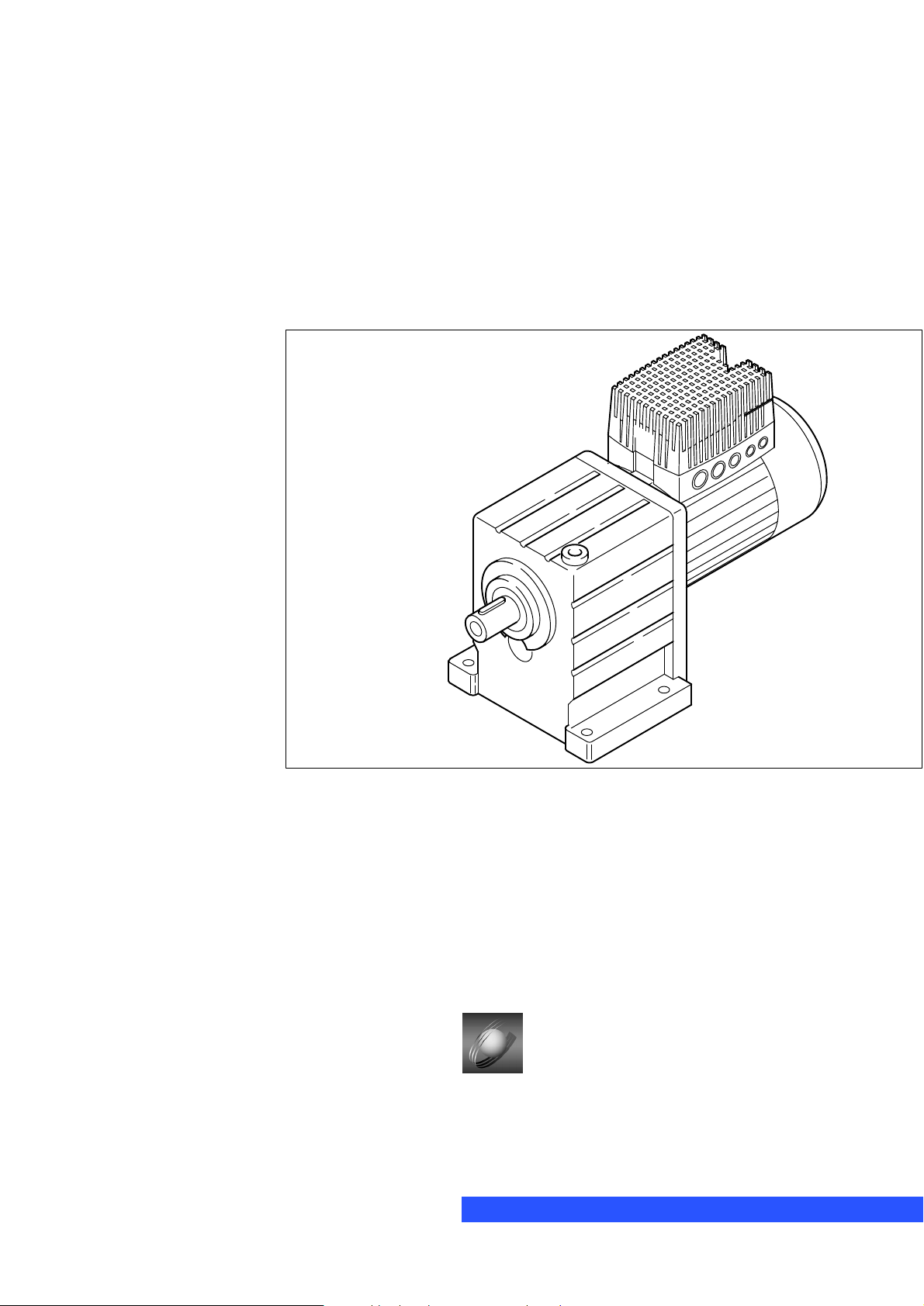
8200 motec frequency inverter
0.25 kW ... 7.5 kW
Page 2
This documentation is valid for 8200 motec controllers as of version
E82MV xxx _ x B xxx XX XX 3x
Type
Power
2
(e.g. 152 = 15 10
(e.g. 113 = 11 10
Voltage class
2 = 240 V
4 = 400 V/500 V
Device version
Hardware version
Software version
W = 1.5 kW)
3
W = 11 kW)
When 8200 motec controllers are operated together with Lenze motors or Lenze geared motors, these instructions
are only valid together with the operating instructions for the motors and geared motors.
In the event of service, please state the exact type designation. The function module used can either be identified
through the keypad, the PC , or by means of the nameplate stuck on the carrier housing. Moreover, each function
module is clearly designated (e.g. STANDARD" for standard I/O).
What is new / what has changed in the Operating Instructions?
Material number
00402783 1.0 07/98 TD00 1. edition First edition for pilot series
00404604 2.0 11/98 TD00 2. edition
00422543 3.0 09/01 TD02 3. edition
00459196 4.0 11/02 TD01 4. edition
13206840 5.1 07/07 TD14 5. edition Extended by device version with electronic switching output K1
Edition Important Contents
Replaces
402783
Replaces
404604
Replaces
422543
4.1 02/03 TD15 Replaces
459196
Complete revision for series
All chapters: error correction and complete editorial revision
Extended by frequency inverter 0.25 kW/0.37 kW and 3 kW ... 7.5 kW,
Chapter 3 Technical data": extended by powers 0.25/0.37 kW u. 3..7.5 kW
Chapter. 5 Commissioning": extended by step for step commissioning
Chapter 12 Accessories": extended and updated
All chapters: update, error correction and complete editorial revision
Change of company name
Chapter 11 "Braking operation": update
Chapter 4.2.1.5, 8, 11.2: update
Chapter 4.2.2.5: removed; chapter 4.2.4.4: reference to Communication Manual
Chapter 5.4 − 5.5: internal reorganisation
Chapter 11.3.2 u 11.3.3: update of brake resistor data
Chapter 14: signal flow diagrams (without AIF) updated/newly arranged and code table
updated according to SW 3.7
Layout corrections:
Chapter 13.1: Table of the application−specific configuration:
− Correction of mixed up example values in code 412/1 and 412/5
− Supplement of code 0415
2006 Lenze Drive Systems GmbH
No part of this documentation may be copied or made available without the explicit written approval of Lenze Drive Systems GmbH.
We have compiled all information in this documentation with great care and have checked them with regard to compliance with the hardware and software
described. Nevertheless, we cannot entirely exclude deviations. We do not accept legal responsibility or liability for damage possibly resulting therefrom.
We will include necessary amendments in the subsequent editions.
Version 5.2 08/2007
Page 3

Contents
1 Preface and general information 1−1 . . . . . . . . . . . . . . . . . . . . . . . . . . . . . . . . . . . . . . . . . . .
1.1 The 8200 motec frequency inverter 1−1 . . . . . . . . . . . . . . . . . . . . . . . . . . . . . . . . . . . . . . . . . . . . . . . . . . . .
1.2 About these Operating Instructions ... 1−1 . . . . . . . . . . . . . . . . . . . . . . . . . . . . . . . . . . . . . . . . . . . . . . . . . .
1.3 Terminology used 1−1 . . . . . . . . . . . . . . . . . . . . . . . . . . . . . . . . . . . . . . . . . . . . . . . . . . . . . . . . . . . . . . . . .
1.4 Legal regulations 1−2 . . . . . . . . . . . . . . . . . . . . . . . . . . . . . . . . . . . . . . . . . . . . . . . . . . . . . . . . . . . . . . . . .
2 Safety information 2−1 . . . . . . . . . . . . . . . . . . . . . . . . . . . . . . . . . . . . . . . . . . . . . . . . . . . . . .
2.1 General safety and application instructions for Lenze controllers 2−1 . . . . . . . . . . . . . . . . . . . . . . . . . . . . . .
2.2 General safety and application instructions for Lenze motors 2−3 . . . . . . . . . . . . . . . . . . . . . . . . . . . . . . . . .
2.3 Residual hazards 2−5 . . . . . . . . . . . . . . . . . . . . . . . . . . . . . . . . . . . . . . . . . . . . . . . . . . . . . . . . . . . . . . . . .
2.4 Layout of the safety information 2−5 . . . . . . . . . . . . . . . . . . . . . . . . . . . . . . . . . . . . . . . . . . . . . . . . . . . . . .
3 Technical data 3−1 . . . . . . . . . . . . . . . . . . . . . . . . . . . . . . . . . . . . . . . . . . . . . . . . . . . . . . . . .
3.1 General data/operating conditions 3−1 . . . . . . . . . . . . . . . . . . . . . . . . . . . . . . . . . . . . . . . . . . . . . . . . . . . . .
3.2 Rated data at a mains voltage of 230 V 3−5 . . . . . . . . . . . . . . . . . . . . . . . . . . . . . . . . . . . . . . . . . . . . . . . . .
3.2.1 Operation with rated power (normal operation) 3−5 . . . . . . . . . . . . . . . . . . . . . . . . . . . . . . . . . . . .
3.2.2 Operation with increased rated power 3−6 . . . . . . . . . . . . . . . . . . . . . . . . . . . . . . . . . . . . . . . . . .
3.3 Rated data at a mains voltage of 400/500 V 3−7 . . . . . . . . . . . . . . . . . . . . . . . . . . . . . . . . . . . . . . . . . . . . .
3.3.1 Operation with rated power (normal operation) 3−7 . . . . . . . . . . . . . . . . . . . . . . . . . . . . . . . . . . . .
3.3.2 Operation with increased rated power 3−9 . . . . . . . . . . . . . . . . . . . . . . . . . . . . . . . . . . . . . . . . . .
4 Installation 4−1 . . . . . . . . . . . . . . . . . . . . . . . . . . . . . . . . . . . . . . . . . . . . . . . . . . . . . . . . . . . .
4.1 Mechanical installation 4−1 . . . . . . . . . . . . . . . . . . . . . . . . . . . . . . . . . . . . . . . . . . . . . . . . . . . . . . . . . . . . .
4.1.1 Important notes 4−1 . . . . . . . . . . . . . . . . . . . . . . . . . . . . . . . . . . . . . . . . . . . . . . . . . . . . . . . . . . .
4.1.2 Mechanical design 4−1 . . . . . . . . . . . . . . . . . . . . . . . . . . . . . . . . . . . . . . . . . . . . . . . . . . . . . . . .
4.1.3 Dimensions 4−2 . . . . . . . . . . . . . . . . . . . . . . . . . . . . . . . . . . . . . . . . . . . . . . . . . . . . . . . . . . . . . .
4.2 Electrical installation 4−3 . . . . . . . . . . . . . . . . . . . . . . . . . . . . . . . . . . . . . . . . . . . . . . . . . . . . . . . . . . . . . .
4.2.1 Important notes 4−3 . . . . . . . . . . . . . . . . . . . . . . . . . . . . . . . . . . . . . . . . . . . . . . . . . . . . . . . . . . .
4.2.1.1 Protection of persons 4−3 . . . . . . . . . . . . . . . . . . . . . . . . . . . . . . . . . . . . . . . . . . . . .
4.2.1.2 Motor protection 4−3 . . . . . . . . . . . . . . . . . . . . . . . . . . . . . . . . . . . . . . . . . . . . . . . . .
4.2.1.3 Mains types/mains conditions 4−4 . . . . . . . . . . . . . . . . . . . . . . . . . . . . . . . . . . . . . . .
4.2.1.4 Operation on public supply systems (compliance with EN 61000−3−2) 4−4 . . . . . . . . . .
4.2.1.5 Operation with earth−leakage circuit breaker 4−5 . . . . . . . . . . . . . . . . . . . . . . . . . . . .
4.2.1.6 Interaction with compensation equipment 4−5 . . . . . . . . . . . . . . . . . . . . . . . . . . . . . .
4.2.1.7 Specification of the cables used 4−6 . . . . . . . . . . . . . . . . . . . . . . . . . . . . . . . . . . . . .
4.2.2 Installation according to EMC 4−7 . . . . . . . . . . . . . . . . . . . . . . . . . . . . . . . . . . . . . . . . . . . . . . . . .
4.2.2.1 Assembly 4−7 . . . . . . . . . . . . . . . . . . . . . . . . . . . . . . . . . . . . . . . . . . . . . . . . . . . . . .
4.2.2.2 Filters 4−7 . . . . . . . . . . . . . . . . . . . . . . . . . . . . . . . . . . . . . . . . . . . . . . . . . . . . . . . .
4.2.2.3 Shielding 4−7 . . . . . . . . . . . . . . . . . . . . . . . . . . . . . . . . . . . . . . . . . . . . . . . . . . . . . .
4.2.2.4 Earthing 4−7 . . . . . . . . . . . . . . . . . . . . . . . . . . . . . . . . . . . . . . . . . . . . . . . . . . . . . . .
4.2.3 Power connections 4−8 . . . . . . . . . . . . . . . . . . . . . . . . . . . . . . . . . . . . . . . . . . . . . . . . . . . . . . . .
4.2.4 Control connections 4−8 . . . . . . . . . . . . . . . . . . . . . . . . . . . . . . . . . . . . . . . . . . . . . . . . . . . . . . . .
4.2.4.1 Mounting/dismounting the I/O function module 4−8 . . . . . . . . . . . . . . . . . . . . . . . . . .
4.2.4.2 Terminal assignment − standard I/O E82ZAFSC001 4−9 . . . . . . . . . . . . . . . . . . . . . . . .
4.2.4.3 Terminal assignment − application I/O E82ZAFAC001 4−12 . . . . . . . . . . . . . . . . . . . . . .
4.2.4.4 Wiring of bus function modules 4−16 . . . . . . . . . . . . . . . . . . . . . . . . . . . . . . . . . . . . . .
L EDB82MV752 EN 5.2
i
Page 4

Contents
5 Commissioning 5−1 . . . . . . . . . . . . . . . . . . . . . . . . . . . . . . . . . . . . . . . . . . . . . . . . . . . . . . . .
5.1 Before you start 5−1 . . . . . . . . . . . . . . . . . . . . . . . . . . . . . . . . . . . . . . . . . . . . . . . . . . . . . . . . . . . . . . . . . .
5.2 Before switching on 5−1 . . . . . . . . . . . . . . . . . . . . . . . . . . . . . . . . . . . . . . . . . . . . . . . . . . . . . . . . . . . . . .
5.2.1 Menu structure 5−2 . . . . . . . . . . . . . . . . . . . . . . . . . . . . . . . . . . . . . . . . . . . . . . . . . . . . . . . . . . .
5.2.2 Changing and saving parameters 5−3 . . . . . . . . . . . . . . . . . . . . . . . . . . . . . . . . . . . . . . . . . . . . . .
5.3 Selection of the correct control mode 5−4 . . . . . . . . . . . . . . . . . . . . . . . . . . . . . . . . . . . . . . . . . . . . . . . . . .
5.4 Commissioning − V/f characteristic control 5−6 . . . . . . . . . . . . . . . . . . . . . . . . . . . . . . . . . . . . . . . . . . . . . .
5.4.1 Commissioning without function module 5−6 . . . . . . . . . . . . . . . . . . . . . . . . . . . . . . . . . . . . . . . . .
5.4.2 Commissioning with standard I/O function module 5−8 . . . . . . . . . . . . . . . . . . . . . . . . . . . . . . . . .
5.5 Commissioning − vector control 5−10 . . . . . . . . . . . . . . . . . . . . . . . . . . . . . . . . . . . . . . . . . . . . . . . . . . . . . .
5.5.1 Commissioning without function module 5−10 . . . . . . . . . . . . . . . . . . . . . . . . . . . . . . . . . . . . . . . . .
5.5.2 Commissioning with standard I/O function module 5−12 . . . . . . . . . . . . . . . . . . . . . . . . . . . . . . . . .
5.5.3 Vector control optimisation 5−14 . . . . . . . . . . . . . . . . . . . . . . . . . . . . . . . . . . . . . . . . . . . . . . . . . . .
6 Parameter setting 6−1 . . . . . . . . . . . . . . . . . . . . . . . . . . . . . . . . . . . . . . . . . . . . . . . . . . . . . .
6.1 General information 6−1 . . . . . . . . . . . . . . . . . . . . . . . . . . . . . . . . . . . . . . . . . . . . . . . . . . . . . . . . . . . . . . .
6.2 Parameter setting via keypad 6−2 . . . . . . . . . . . . . . . . . . . . . . . . . . . . . . . . . . . . . . . . . . . . . . . . . . . . . . . .
6.2.1 Installation/commissioning 6−2 . . . . . . . . . . . . . . . . . . . . . . . . . . . . . . . . . . . . . . . . . . . . . . . . . . .
6.2.2 Displays and functions 6−2 . . . . . . . . . . . . . . . . . . . . . . . . . . . . . . . . . . . . . . . . . . . . . . . . . . . . . .
6.2.3 Menu structure 6−4 . . . . . . . . . . . . . . . . . . . . . . . . . . . . . . . . . . . . . . . . . . . . . . . . . . . . . . . . . . .
6.2.4 Changing and saving parameters using the keypad 6−5 . . . . . . . . . . . . . . . . . . . . . . . . . . . . . . . . .
6.2.5 Change parameter set 6−5 . . . . . . . . . . . . . . . . . . . . . . . . . . . . . . . . . . . . . . . . . . . . . . . . . . . . . .
6.2.6 Remote parameterisation of system bus nodes 6−6 . . . . . . . . . . . . . . . . . . . . . . . . . . . . . . . . . . . .
6.2.7 Change entries in the user menu 6−6 . . . . . . . . . . . . . . . . . . . . . . . . . . . . . . . . . . . . . . . . . . . . . .
6.2.8 Activation of password protection 6−7 . . . . . . . . . . . . . . . . . . . . . . . . . . . . . . . . . . . . . . . . . . . . . .
6.3 Parameter setting using the LECOM−A(RS232) communication module 6−9 . . . . . . . . . . . . . . . . . . . . . . . . .
6.3.1 Technical data 6−9 . . . . . . . . . . . . . . . . . . . . . . . . . . . . . . . . . . . . . . . . . . . . . . . . . . . . . . . . . . . .
6.3.1.1 General data/operating conditions 6−9 . . . . . . . . . . . . . . . . . . . . . . . . . . . . . . . . . . . .
6.3.1.2 Communication times 6−10 . . . . . . . . . . . . . . . . . . . . . . . . . . . . . . . . . . . . . . . . . . . . .
6.3.2 Wiring to a host (PC or PLC) 6−11 . . . . . . . . . . . . . . . . . . . . . . . . . . . . . . . . . . . . . . . . . . . . . . . . . .
6.3.2.1 Notes on self−made PC system cables 6−11 . . . . . . . . . . . . . . . . . . . . . . . . . . . . . . . . .
6.3.3 Parameter setting using LECOM−A (RS232) 6−12 . . . . . . . . . . . . . . . . . . . . . . . . . . . . . . . . . . . . . . .
6.3.4 Additional codes for LECOM−A (RS232) 6−12 . . . . . . . . . . . . . . . . . . . . . . . . . . . . . . . . . . . . . . . . . .
6.3.5 Troubleshooting and fault elimination LECOM−A (RS232) 6−16 . . . . . . . . . . . . . . . . . . . . . . . . . . . . .
7 Function library 7−1 . . . . . . . . . . . . . . . . . . . . . . . . . . . . . . . . . . . . . . . . . . . . . . . . . . . . . . . .
7.1 Operating mode 7−2 . . . . . . . . . . . . . . . . . . . . . . . . . . . . . . . . . . . . . . . . . . . . . . . . . . . . . . . . . . . . . . . . .
7.1.1 V/f characteristic control 7−4 . . . . . . . . . . . . . . . . . . . . . . . . . . . . . . . . . . . . . . . . . . . . . . . . . . .
7.1.2 Vector control 7−8 . . . . . . . . . . . . . . . . . . . . . . . . . . . . . . . . . . . . . . . . . . . . . . . . . . . . . . . . . . .
7.1.3 Sensorless torque control with speed limitation 7−10 . . . . . . . . . . . . . . . . . . . . . . . . . . . . . . . . . . .
7.2 Optimising the operating behaviour 7−13 . . . . . . . . . . . . . . . . . . . . . . . . . . . . . . . . . . . . . . . . . . . . . . . . . . .
7.2.1 Slip compensation 7−13 . . . . . . . . . . . . . . . . . . . . . . . . . . . . . . . . . . . . . . . . . . . . . . . . . . . . . . . .
7.2.2 Inverter switching frequency 7−14 . . . . . . . . . . . . . . . . . . . . . . . . . . . . . . . . . . . . . . . . . . . . . . . . .
7.2.3 Oscillation damping 7−16 . . . . . . . . . . . . . . . . . . . . . . . . . . . . . . . . . . . . . . . . . . . . . . . . . . . . . . .
7.2.4 Skip frequencies 7−17 . . . . . . . . . . . . . . . . . . . . . . . . . . . . . . . . . . . . . . . . . . . . . . . . . . . . . . . . .
7.3 Behaviour in the event of mains switching, mains failure or controller inhibit 7−18 . . . . . . . . . . . . . . . . . . . . .
ii
EDB82MV752 EN 5.2
L
Page 5

Contents
7.3.1 Start conditions/flying−restart circuit 7−18 . . . . . . . . . . . . . . . . . . . . . . . . . . . . . . . . . . . . . . . . . . .
7.3.2 Controlled deceleration after mains failure/mains disconnection 7−19 . . . . . . . . . . . . . . . . . . . . . . .
7.3.3 Controller inhibit 7−20 . . . . . . . . . . . . . . . . . . . . . . . . . . . . . . . . . . . . . . . . . . . . . . . . . . . . . . . . . .
7.4 Limit value setting 7−21 . . . . . . . . . . . . . . . . . . . . . . . . . . . . . . . . . . . . . . . . . . . . . . . . . . . . . . . . . . . . . . .
7.4.1 Speed range 7−21 . . . . . . . . . . . . . . . . . . . . . . . . . . . . . . . . . . . . . . . . . . . . . . . . . . . . . . . . . . . . .
7.4.2 Current limits 7−23 . . . . . . . . . . . . . . . . . . . . . . . . . . . . . . . . . . . . . . . . . . . . . . . . . . . . . . . . . . .
7.5 Acceleration, deceleration, braking, stopping 7−24 . . . . . . . . . . . . . . . . . . . . . . . . . . . . . . . . . . . . . . . . . . . .
7.5.1 Setting of acceleration times, deceleration times and S−shaped ramps 7−24 . . . . . . . . . . . . . . . . . .
7.5.2 Quick stop 7−27 . . . . . . . . . . . . . . . . . . . . . . . . . . . . . . . . . . . . . . . . . . . . . . . . . . . . . . . . . . . . . . .
7.5.3 Change of direction of rotation 7−28 . . . . . . . . . . . . . . . . . . . . . . . . . . . . . . . . . . . . . . . . . . . . . . .
7.5.4 DC braking (DCB) 7−30 . . . . . . . . . . . . . . . . . . . . . . . . . . . . . . . . . . . . . . . . . . . . . . . . . . . . . . . . .
7.5.5 AC motor braking 7−31 . . . . . . . . . . . . . . . . . . . . . . . . . . . . . . . . . . . . . . . . . . . . . . . . . . . . . . . . .
7.6 Configuration of analog and digital setpoints and actual values 7−32 . . . . . . . . . . . . . . . . . . . . . . . . . . . . . .
7.6.1 Setpoint source selection 7−32 . . . . . . . . . . . . . . . . . . . . . . . . . . . . . . . . . . . . . . . . . . . . . . . . . . .
7.6.2 Analog setpoints via terminal 7−34 . . . . . . . . . . . . . . . . . . . . . . . . . . . . . . . . . . . . . . . . . . . . . . . .
7.6.3 Digital setpoints via frequency input 7−39 . . . . . . . . . . . . . . . . . . . . . . . . . . . . . . . . . . . . . . . . . . .
7.6.4 Setpoints via function "motor potentiometer" 7−41 . . . . . . . . . . . . . . . . . . . . . . . . . . . . . . . . . . . . .
7.6.5 Setpoints via fixed setpoints (JOG) 7−43 . . . . . . . . . . . . . . . . . . . . . . . . . . . . . . . . . . . . . . . . . . . .
7.6.6 Setpoints via keypad 7−45 . . . . . . . . . . . . . . . . . . . . . . . . . . . . . . . . . . . . . . . . . . . . . . . . . . . . . .
7.6.7 Setpoints via a bus system 7−46 . . . . . . . . . . . . . . . . . . . . . . . . . . . . . . . . . . . . . . . . . . . . . . . . . .
7.6.8 Setpoint changeover (hand/remote changeover) 7−47 . . . . . . . . . . . . . . . . . . . . . . . . . . . . . . . . . . .
7.7 Automatic detection of motor data 7−48 . . . . . . . . . . . . . . . . . . . . . . . . . . . . . . . . . . . . . . . . . . . . . . . . . . . .
7.8 Process controller 7−50 . . . . . . . . . . . . . . . . . . . . . . . . . . . . . . . . . . . . . . . . . . . . . . . . . . . . . . . . . . . . . . . .
7.8.1 Setting of control characteristics 7−50 . . . . . . . . . . . . . . . . . . . . . . . . . . . . . . . . . . . . . . . . . . . . . .
7.8.2 Setpoint selection for the process controller 7−53 . . . . . . . . . . . . . . . . . . . . . . . . . . . . . . . . . . . . .
7.8.3 Actual value selection for the process controller 7−54 . . . . . . . . . . . . . . . . . . . . . . . . . . . . . . . . . .
7.8.4 Switching off process controller functions 7−55 . . . . . . . . . . . . . . . . . . . . . . . . . . . . . . . . . . . . . . .
7.9 Current−limit controller 7−56 . . . . . . . . . . . . . . . . . . . . . . . . . . . . . . . . . . . . . . . . . . . . . . . . . . . . . . . . . . . .
7.10 Free interconnection of analog signals 7−57 . . . . . . . . . . . . . . . . . . . . . . . . . . . . . . . . . . . . . . . . . . . . . . .
7.10.1 Free configuration of analog input signals 7−57 . . . . . . . . . . . . . . . . . . . . . . . . . . . . . . . . . . . . . . .
7.10.2 Free configuration of analog outputs 7−59 . . . . . . . . . . . . . . . . . . . . . . . . . . . . . . . . . . . . . . . . . . .
7.10.3 Free configuration of analog process data output words 7−64 . . . . . . . . . . . . . . . . . . . . . . . . . . . . .
7.11 Free interconnection of digital signals 7−68 . . . . . . . . . . . . . . . . . . . . . . . . . . . . . . . . . . . . . . . . . . . . . . . . .
7.11.1 Free configuration of digital input signals 7−68 . . . . . . . . . . . . . . . . . . . . . . . . . . . . . . . . . . . . . . . .
7.11.2 Free configuration of digital outputs 7−73 . . . . . . . . . . . . . . . . . . . . . . . . . . . . . . . . . . . . . . . . . . .
7.11.3 Free configuration of digital process data output words 7−79 . . . . . . . . . . . . . . . . . . . . . . . . . . . . .
7.12 Thermal motor monitoring 7−82 . . . . . . . . . . . . . . . . . . . . . . . . . . . . . . . . . . . . . . . . . . . . . . . . . . . . . . . . . .
7.12.1 I2t monitoring 7−82 . . . . . . . . . . . . . . . . . . . . . . . . . . . . . . . . . . . . . . . . . . . . . . . . . . . . . . . . . . . .
7.12.2 Temperature monitoring of the motor with PTC and earth−fault detection 7−84 . . . . . . . . . . . . . . . .
7.13 External fault evaluation 7−85 . . . . . . . . . . . . . . . . . . . . . . . . . . . . . . . . . . . . . . . . . . . . . . . . . . . . . . . . . . .
7.13.1 External fault detection 7−85 . . . . . . . . . . . . . . . . . . . . . . . . . . . . . . . . . . . . . . . . . . . . . . . . . . . . .
7.13.2 Reset of external faults 7−85 . . . . . . . . . . . . . . . . . . . . . . . . . . . . . . . . . . . . . . . . . . . . . . . . . . . . .
7.14 Display of operating data, diagnostics 7−86 . . . . . . . . . . . . . . . . . . . . . . . . . . . . . . . . . . . . . . . . . . . . . . . . .
7.14.1 Display of operating data 7−86 . . . . . . . . . . . . . . . . . . . . . . . . . . . . . . . . . . . . . . . . . . . . . . . . . . .
7.14.2 Diagnostics 7−89 . . . . . . . . . . . . . . . . . . . . . . . . . . . . . . . . . . . . . . . . . . . . . . . . . . . . . . . . . . . . .
L EDB82MV752 EN 5.2
iii
Page 6

Contents
7.15 Parameter set management 7−91 . . . . . . . . . . . . . . . . . . . . . . . . . . . . . . . . . . . . . . . . . . . . . . . . . . . . . . . . .
7.15.1 Saving and copying parameter sets 7−91 . . . . . . . . . . . . . . . . . . . . . . . . . . . . . . . . . . . . . . . . . . . .
7.15.2 Parameter set changeover 7−94 . . . . . . . . . . . . . . . . . . . . . . . . . . . . . . . . . . . . . . . . . . . . . . . . . .
7.16 Individual summary of drive parameters in the user menu 7−95 . . . . . . . . . . . . . . . . . . . . . . . . . . . . . . . . . . .
8 Troubleshooting and fault elimination 8−1 . . . . . . . . . . . . . . . . . . . . . . . . . . . . . . . . . . . . . .
8.1 Troubleshooting 8−1 . . . . . . . . . . . . . . . . . . . . . . . . . . . . . . . . . . . . . . . . . . . . . . . . . . . . . . . . . . . . . . . . . .
8.1.1 Status display (LEDs on the controller) 8−1 . . . . . . . . . . . . . . . . . . . . . . . . . . . . . . . . . . . . . . . . . .
8.2 LEDs on the drive controller (status display) 8−1 . . . . . . . . . . . . . . . . . . . . . . . . . . . . . . . . . . . . . . . . . . . . .
8.2.1 Error analysis with the history buffer 8−1 . . . . . . . . . . . . . . . . . . . . . . . . . . . . . . . . . . . . . . . . . . .
8.3 Drive performance in case of errors 8−2 . . . . . . . . . . . . . . . . . . . . . . . . . . . . . . . . . . . . . . . . . . . . . . . . . . .
8.4 Error elimination 8−3 . . . . . . . . . . . . . . . . . . . . . . . . . . . . . . . . . . . . . . . . . . . . . . . . . . . . . . . . . . . . . . . . .
8.4.1 Maloperation of the drive 8−3 . . . . . . . . . . . . . . . . . . . . . . . . . . . . . . . . . . . . . . . . . . . . . . . . . . .
8.4.2 Fault messages on the keypad or in the parameter setting program Global Drive Control 8−4 . . . . .
8.5 Resetting error messages 8−7 . . . . . . . . . . . . . . . . . . . . . . . . . . . . . . . . . . . . . . . . . . . . . . . . . . . . . . . . . .
9 Automation 9−1 . . . . . . . . . . . . . . . . . . . . . . . . . . . . . . . . . . . . . . . . . . . . . . . . . . . . . . . . . . .
9.1 System bus function module (CAN) E82ZAFC 9−1 . . . . . . . . . . . . . . . . . . . . . . . . . . . . . . . . . . . . . . . . . . . . .
10 DC−bus connection 10−1 . . . . . . . . . . . . . . . . . . . . . . . . . . . . . . . . . . . . . . . . . . . . . . . . . . . . .
11 Braking operation 11−1 . . . . . . . . . . . . . . . . . . . . . . . . . . . . . . . . . . . . . . . . . . . . . . . . . . . . . .
11.1 Braking operation without additional measures 11−1 . . . . . . . . . . . . . . . . . . . . . . . . . . . . . . . . . . . . . . . . . . .
11.2 Braking operation with external brake resistor 11−1 . . . . . . . . . . . . . . . . . . . . . . . . . . . . . . . . . . . . . . . . . . . .
11.2.1 Selection of brake resistors 11−1 . . . . . . . . . . . . . . . . . . . . . . . . . . . . . . . . . . . . . . . . . . . . . . . . . .
11.2.2 Rated data of the integrated brake transistor 11−2 . . . . . . . . . . . . . . . . . . . . . . . . . . . . . . . . . . . . .
11.2.3 Rated data of Lenze brake resistors 11−3 . . . . . . . . . . . . . . . . . . . . . . . . . . . . . . . . . . . . . . . . . . . .
12 Accessories 12−1 . . . . . . . . . . . . . . . . . . . . . . . . . . . . . . . . . . . . . . . . . . . . . . . . . . . . . . . . . . .
13 Application examples 13−1 . . . . . . . . . . . . . . . . . . . . . . . . . . . . . . . . . . . . . . . . . . . . . . . . . . .
13.1 Pressure control 13−1 . . . . . . . . . . . . . . . . . . . . . . . . . . . . . . . . . . . . . . . . . . . . . . . . . . . . . . . . . . . . . . . . . .
13.1.1 Example 1: Simple pressure control with fixed setpoint selection 13−5 . . . . . . . . . . . . . . . . . . . . . . .
13.1.2 Example 2: Simple pressure control with changeable setpoint selection 13−7 . . . . . . . . . . . . . . . . . .
13.2 Operation with mid−frequency motors 13−9 . . . . . . . . . . . . . . . . . . . . . . . . . . . . . . . . . . . . . . . . . . . . . . . . . .
13.3 Speed control 13−10 . . . . . . . . . . . . . . . . . . . . . . . . . . . . . . . . . . . . . . . . . . . . . . . . . . . . . . . . . . . . . . . . . . .
13.4 Group drive (operation with several motors) 13−13 . . . . . . . . . . . . . . . . . . . . . . . . . . . . . . . . . . . . . . . . . . . . . .
13.5 Setpoint summation (base and additional load operation) 13−14 . . . . . . . . . . . . . . . . . . . . . . . . . . . . . . . . . . . .
13.6 Power control (torque limitation) 13−15 . . . . . . . . . . . . . . . . . . . . . . . . . . . . . . . . . . . . . . . . . . . . . . . . . . . . . .
14 Appendix 14−1 . . . . . . . . . . . . . . . . . . . . . . . . . . . . . . . . . . . . . . . . . . . . . . . . . . . . . . . . . . . . .
14.1 Signal flow diagrams 14−1 . . . . . . . . . . . . . . . . . . . . . . . . . . . . . . . . . . . . . . . . . . . . . . . . . . . . . . . . . . . .
14.2 Overview of signal processing of standard I/O 14−2 . . . . . . . . . . . . . . . . . . . . . . . . . . . . . . . . . . . . . . . . . . . .
14.2.1 Controller with standard I/O 14−2 . . . . . . . . . . . . . . . . . . . . . . . . . . . . . . . . . . . . . . . . . . . . . . . . . .
iv
EDB82MV752 EN 5.2
L
Page 7

Contents
14.3 Signal processing in the standard I/O function blocks 14−3 . . . . . . . . . . . . . . . . . . . . . . . . . . . . . . . . . . . . . .
14.3.1 Speed setpoint conditioning (NSET1) 14−3 . . . . . . . . . . . . . . . . . . . . . . . . . . . . . . . . . . . . . . . . . . .
14.3.2 Process controller and setpoint processing (PCTRL1) 14−4 . . . . . . . . . . . . . . . . . . . . . . . . . . . . . . . .
14.3.3 Motor control (MCTRL1) 14−5 . . . . . . . . . . . . . . . . . . . . . . . . . . . . . . . . . . . . . . . . . . . . . . . . . . . . .
14.4 Overview of signal processing of the application I/O 14−6 . . . . . . . . . . . . . . . . . . . . . . . . . . . . . . . . . . . . . . .
14.4.1 Controller with application I/O 14−6 . . . . . . . . . . . . . . . . . . . . . . . . . . . . . . . . . . . . . . . . . . . . . . . .
14.5 Signal processing in the application I/O function blocks 14−7 . . . . . . . . . . . . . . . . . . . . . . . . . . . . . . . . . . . . .
14.5.1 Speed setpoint conditioning (NSET1) 14−7 . . . . . . . . . . . . . . . . . . . . . . . . . . . . . . . . . . . . . . . . . . .
14.5.2 Process controller and setpoint processing (PCTRL1) with Application I/O 14−8 . . . . . . . . . . . . . . . . .
14.5.3 Motor control (MCTRL1) with Application I/O 14−9 . . . . . . . . . . . . . . . . . . . . . . . . . . . . . . . . . . . . . .
14.6 Code table 14−10 . . . . . . . . . . . . . . . . . . . . . . . . . . . . . . . . . . . . . . . . . . . . . . . . . . . . . . . . . . . . . . . . . . . . . .
14.7 Table of attributes 14−51 . . . . . . . . . . . . . . . . . . . . . . . . . . . . . . . . . . . . . . . . . . . . . . . . . . . . . . . . . . . . . . . .
14.7.1 Standard devices in the power range 0.25 ... 7.5 kW with standard I/O 14−52 . . . . . . . . . . . . . . . . . .
14.7.2 Standard devices in the power range 0.25 ... 7.5 kW with application I/O 14−56 . . . . . . . . . . . . . . . .
15 Table of keywords 15−1 . . . . . . . . . . . . . . . . . . . . . . . . . . . . . . . . . . . . . . . . . . . . . . . . . . . . . .
L EDB82MV752 EN 5.2
v
Page 8

Preface and general information
1 Preface and general information
1.1 The 8200 motec frequency inverter
Decentralised drive solutions require a flexible combination of motor/geared motor and frequency
inverter.
The concept of the 8200 motec frequency inverter is therefore based on a modular system of
matching components. Together with a Lenze geared motor or a Lenze three−phase AC motor the
8200 motec is a highly functional electronic variable speed drive.
As compact drives they can be used for adjusting speeds in different application, such as material
handling, HVAC technology, automation, etc. A free combination of input and output signals and
parallel operation of two interfaces ensure an individual solution for your drive task.
The 8200 motec frequency inverter is directly mounted onto the motor. Wall mounting of the
8200 motec is also possible.
1.2 About these Operating Instructions ...
These Operating Instructions are intended for all persons who install, set−up and adjust the
8200 motec frequency inverter.
A chapter informs entirely about a subject:
– You therefore only have to read the chapters you are interested in at the moment.
– The Index helps you to find all information about a certain topic.
These Instructions are meant as addition to the Mounting Instructions which are part of the
delivery package:
– The features and funtions are described in detail.
– Examples describe how to set the parameters for typical applications.
– In case of doubt, the Mounting Instructions delivered together with the 8200 motec
frequency inverter apply.
The Mounting Instructions do not inform about the use together with Lenze geared motors
and Lenze motors. The most important data are listed on the nameplates. If necessary,
Operating Instructions can always be ordered from Lenze.
1.3 Terminology used
Term In the following text used for
Controller Any frequency inverter, servo inverter or DC controller
motec Frequency inverter 8200 motec
Drive 8200 motec in combination with a geared motor, a three−phase AC motor and other Lenze drive components
AIF AutomationInterF ace: Interface for a communication module. Accessible from the outside at the heatsink of the motec.
FIF F unctionInterF ace: Interface for a function module. Is inside the motec.
Cxxxx/y Subcode y of code Cxxxx (e.g. C0517/3 = subcode 3 of code C0517)
Xk/y Terminal y on terminal strip Xk (e. g. X3/28 = terminal 28 on terminal strip X3)
L EDB82MV752 EN 5.2
1−1
Page 9

Preface and general information
1.4 Legal regulations
Labelling
Application as
directed
Nameplate CE−identification Manufacturer
Lenze controllers are unambiguously
designated by the contents of the nameplate.
8200 motec frequency inverter and accessories
Conforms to the EC Low Voltage Directive Lenze Drive Systems GmbH
Postfach 10 13 52
D−31763 Hameln
must only be operated under the conditions prescribed in these Operating Instructions.
are components
– for open and closed loop control of variable speed drives with asynchronous standard motors, reluctance motors, PM synchronous
motors with asynchronous damping cage.
– for installation into a machine
– used for assembly together with other components to form a machine.
comply with the requirements of the EC Low−Voltage Directive.
are not machines for the purpose of the EC Machinery Directive.
are not to be used as domestic appliances, but only for industrial purposes.
Drives with 8200 motec frequency inverters
meet the EC Electromagnetic Compatibility Directive if they are installed according to the guidelines of CE−typical drive systems.
can be used
– for operation on public and non−public mains
– for operation in industrial premises and residential areas.
The user is responsible for the compliance of his application with the EC directives.
Any other use shall be deemed inappropriate!
Liability The information, data, and notes in these instructions met the state of the art at the time of printing. Claims referring to drive systems
which have already been supplied cannot be derived from the information, illustrations, and descriptions given in these Operating
Instructions.
The specifications, processes, and circuitry described in these instructions are for guidance only and must be adapted to your own specific
application. Lenze does not take responsibility for the suitability of the process and circuit proposals.
The specifications in these Instructions describe the product features without guaranteeing them.
Lenze does not accept any liability for damage and operating interference caused by:
– disregarding the operating instructions
– unauthorized modifications to the controller
– operating errors
– improper working on and with the controller
Warranty Warranty conditions: see Sales and Delivery Conditions of Lenze Drive Systems GmbH.
Warranty claims must be made to Lenze immediately after detecting the deficiency or fault.
The warranty is void in all cases where liability claims cannot be made.
Disposal
Material recycle dispose
Metal −
Plastic −
Assembled PCBs −
1−2
EDB82MV752 EN 5.2
L
Page 10

Safety instructions
Lenze controllers
2 Safety information
2.1 General safety and application instructions for Lenze controllers
(According to: Low−Voltage Directive 73/23/EEC)
General
Depending on their degree of protection, some parts of Lenze controllers (frequency inverters, servo
inverters, DC controllers) and their accessory components can be live, moving and rotating during
operation. Surfaces can be hot.
Non−authorised removal of the required cover, inappropriate use, incorrect installation or operation,
creates the risk of severe injury to persons or damage to material assets.
For more information please see the documentation.
All operations concerning transport, installation, and commissioning as well as maintenance must be
carried out by qualified, skilled personnel (IEC 364 and CENELEC HD 384 or DIN VDE 0100 and IEC
report 664 or DIN VDE 0110 and national regulations for the prevention of accidents must be observed).
According to this basic safety information, qualified, skilled personnel are persons who are familiar with
the assembly, installation, commissioning, and operation of the product and who have the qualifications
necessary for their occupation.
Application as directed
Drive controllers are components which are designed for installation in electrical systems or machinery.
They are not to be used as domestic appliances, but only for industrial purposes according to
EN 61000−3−2.
When installing drive controllers into machines, commissioning of these controllers (i.e. the starting of
operation as directed) is prohibited until it is proven that the machine corresponds to the regulations of
the EC Directive 98/37/EC (Machinery Directive); EN 60204 must be observed.
Commissioning (i.e. starting of operation as directed) is only allowed when there is compliance with the
EMC Directive (89/336/EEC).
The controllers meet the requirements of the Low−Voltage Directive 73/23/EEC. The harmonised
standard EN 61800−5−1 applies to the controllers.
The technical data as well as the connection conditions can be obtained from the nameplate and the
documentation. They must be strictly observed.
Warning: The controllers are products which can be installed in drive systems of category C2 according
to EN 61800−3. These products can cause radio interference in residential areas. In this case, special
measures can be necessary.
Transport, storage
Please observe the notes on transport, storage and appropriate handling.
Observe the climatic conditions according to the technical data.
Installation
The controllers must be installed and cooled according to the instructions given in the corresponding
documentation.
Ensure proper handling and avoid mechanical stress. Do not bend any components and do not change
any insulation distances during transport or handling. Do not touch any electronic components and
contacts.
Controllers contain electrostatically sensitive components, which can easily be damaged by
inappropriate handling. Do not damage or destroy any electrical components since this might endanger
your health!
L EDB82MV752 EN 5.2
2−1
Page 11

Safety instructions
Lenze controllers
Electrical connection
When working on live controllers, the valid national regulations for the prevention of accidents
(e.g. VBG 4) must be observed.
Carry out the electrical installation in compliance with the corresponding regulations (e.g. cable
cross−sections, fuses, PE connection). More detailed information is given in the corresponding
documentation.
Notes about installation according to EMC regulations (shielding, earthing, filters and cable routing) are
included in the documentation. These notes also apply to CE−marked controllers. The compliance with
limit values required by the EMC legislation is the responsibility of the manufacturer of the machine or
system. The controllers must be installed in housings (e.g. control cabinets) to meet the limit values for
radio interferences valid at the site of installation. The housings must enable an EMC−compliant
installation. Observe in particular that e.g. the control cabinet doors should have a circumferential metal
connection to the housing. Reduce housing openings and cutouts to a minimum.
Lenze controllers can cause a DC current in the protective conductor. If a residual current device (RCD)
is used as a protective means in the case of direct or indirect contact, only a residual current device (RCD)
of type B may be used on the current supply side of the controller. Otherwise, another protective
measure, such as separation from the environment through double or reinforced insulation or
disconnection from the mains by means of a transformer must be used.
Operation
If necessary, systems including controllers must be equipped with additional monitoring and protection
devices according to the valid safety regulations (e.g. law on technical equipment, regulations for the
prevention of accidents). The controller can be adapted to your application. Please observe the
corresponding information given in the documentation.
After a controller has been disconnected from the voltage supply, all live components and power
connections must not be touched immediately because capacitors can still be charged. Please observe
the corresponding stickers on the controller.
All protection covers and doors must be shut during operation.
Note for UL approved systems with integrated controllers: UL warnings are notes that only apply
to UL systems. The documentation contains special UL notes.
Safety functions
Special controller variants support safety functions (e.g. "safe torque off", formerly "safe standstill")
according to the requirements of Annex I No. 1.2.7 of the EC Directive "Machinery" 98/37/EC, EN 954−1
Category 3 and EN 1037. Strictly observe the notes on the safety functions given in the documentation
on the respective variants.
Maintenance and servicing
The controllers do not require any maintenance, if the prescribed conditions of operation are observed.
If the ambient air is polluted, the cooling surfaces of the controller may become dirty or the air vents of
the controller may be obstructed. Therefore, clean the cooling surfaces and air vents periodically under
these operating conditions. Do not use sharp or pointed tools for this purpose!
Waste disposal
Recycle metal and plastic materials. Ensure professional disposal of assembled PCBs.
The product−specific safety and application notes given in these instructions must be observed!
2−2
EDB82MV752 EN 5.2
L
Page 12

Safety instructions
Lenze low−voltage machinery
2.2 General safety and application instructions for Lenze motors
(According to: Low−Voltage Directive 73/23/EEC)
General
Low−voltage machines have hazardous live and rotating parts and possibly also hot surfaces.
Synchronous machines induce voltages at open terminals during operation.
All operations concerning transport, connections, commissioning and maintenance must be carried
out by qualified, skilled personnel (EN 50110−1 (VDE 0105−100) and IEC 60364 must be observed).
Inappropriate use creates the risk of severe injury to persons and damage to material assets.
Low−voltage machines may only be operated under the conditions that are indicated in the section
"Application as directed".
The conditions at the place of installation must comply with the data given on the nameplate and in
the documentation.
Application as directed
Low−voltage machines are intended for commercial installations. They comply with the harmonised
standards of the series EN60034 (VDE 0530). Their use in potentially explosive atmospheres is
prohibited unless they are expressly intended for such use (follow additional instructions).
Low−voltage machines are components for installation into machines as defined in the Machinery
Directive 98/37/EC. Commissioning is prohibited until the conformity of the end product with this
directive has been established (follow i. a. EN 60204−1).
Low−voltage machines with IP23 protection or less are only intended for outdoor use when applying
special protective features.
The integrated brakes must not be used as safety brakes. It cannot be ruled out that factors which
cannot be influenced, such as oil ingress due to a defective A−side shaft seal, cause a brake torque
reduction.
Transport, storage
Damages must be reported immediately upon receipt to the forwarder; if required, commissioning
must be excluded. Tighten screwed−in ring bolts before transport. They are designed for the weight
of the low−voltage machines, do not apply extra loads. If necessary, use suitable and adequately
dimensioned means of transport (e. g. rope guides).
Remove transport locking devices before commissioning. Reuse them for further transport. When
storing low−voltage machines, ensure a dry, dust−free and low−vibration (v
environment (bearing damage while being stored).
Installation
Ensure an even surface, solid foot/flange mounting and exact alignment if a direct clutch is
connected. Avoid resonances with the rotational frequency and double mains frequency which may
be caused by the assembly. Turn rotor by hand, listen for unusual slipping noises. Check the direction
of rotation when the clutch is not active (observe section "Electrical connection").
Use appropriate means to mount or remove belt pulleys and clutches (heating) and cover them with
a touch guard. Avoid impermissible belt tensions.
The machines are half−key balanced. The clutch must be half−key balanced, too. The visible jutting
out part of the key must be removed.
If required, provide pipe connections. Designs with shaft end at bottom must be protected with a
cover which prevents the ingress of foreign particles into the fan. Free circulation of the cooling air
must be ensured. The exhaust air − also the exhaust air of other machines next to the drive system
− must not be taken in immediately.
0.2 mm/s)
eff
L
EDB82MV752 EN 5.2
2−3
Page 13

Safety instructions
Lenze low−voltage machinery
Electrical connection
All operations must only be carried out by qualified and skilled personnel on the low−voltage machine
at standstill and deenergised and provided with a safe guard to prevent an unintentional restart.This
also applies to auxiliary circuits (e. g. brake, encoder, blower).
Check safe isolation from supply!
If the tolerances specified in EN 60034−1; IEC 34 (VDE 0530−1) − voltage ±5 %, frequency ±2 %,
waveform, symmetry − are exceeded, more heat will be generated and the electromagnetic
compatibility will be affected.
Observe the data on the nameplate, operating notes, and the connection diagram in the terminal box.
The connection must ensure a continuous and safe electrical supply (no loose wire ends); use
appropriate cable terminals. The connection to the PE conductor must be safe. The plug−in
connectors must be bolt tightly (to stop).
The clearances between blank, live parts and to earth must not fall below 8 mm at U
at U
725 V, 14 mm at Ur 1000 V.
r
The terminal box must be free of foreign particles, dirt and moisture. All unused cable entries and the
box itself must be sealed against dust and water.
550 V, 10 mm
r
Commissioning and operation
Before commissioning after longer storage periods, measure insulation resistance. In case of values
1 k per volt of rated voltage, dry winding.
For trial run without output elements, lock the featherkey. Do not deactivate the protective devices,
not even in a trial run.
Check the correct operation of the brake before commissioning low−voltage machines with brakes.
Integrated thermal detectors do not provide full protection for the machine. If necessary, limit the
maximum current. Parameterise the controller so that the motor will be switched off with I > I
a few seconds of operation, especially at the risk of blocking.
Vibrational severities v
clutch is activated.
If deviations from normal operation occur, e.g. increased temperatures, noises, vibrations, find the
cause and, if required, contact the manufacturer. In case of doubt, switch off the low−voltage
machine.
If the machine is exposed to dirt, clean the air paths regularly.
Shaft sealing rings and roller bearings have a limited service life.
Regrease bearings with relubricating devices while the low−voltage machine is running. Only use the
grease recommended by the manufacturer. If the grease drain holes are sealed with a plug, (IP54
drive end; IP23 drive and non−drive end), remove plug before commissioning. Seal bore holes with
grease. Replace prelubricated bearings (2Z bearing) after approx. 10,000 h − 20,000 h, at the latest
however after 3 − 4 years.
The product−specific safety and application notes given in these instructions must be
observed!
3.5 mm/s (Pr 15 kW) or 4.5 mm/s (Pr > 15 kW) are acceptable if the
eff
after
r
2−4
EDB82MV752 EN 5.2
L
Page 14
2.3 Residual hazards
Safety instructions
Residual hazards, Layout of the safety instructions
Protection of
persons
Deenergise the motec before you start working on it or open the housing. Wait for at least one minute since the power terminals U, V, W; BR0,
BR1, BR2 and the pins of the FIF interface remain live after switching off the mains.
– After opening the motec, check if the power terminals L1, L2, L3; U, V, W; BR0, BR1, BR2, the relay outputs K11, K12, K14, and the pins of
the FIF interface are dead.
– Even if the motec is disconnected from the mains, the relay outputs K11, K12, K14 can be live!
If you do not use the fail−safe function selection of direction of rotation" via the digital signal DCTRL1−CW/CCW (C0007 = −0− ... −13−, C0410/3
255):
– In case of open circuit or failure of the control voltage, the drive may change the direction of rotation.
If you use the "flying restart circuit" function (C0142 = −2−, −3−) for machines with a low moment of inertia and low friction:
– After controller enable has been effected in the standstill status, the motor may temporarily start up, or change direction of rotation.
The motec heatsink has an operating temperature > 60 °C:
– Skin contact with the heatsink causes burns.
Device
protection
8200 motec 3 ... 7.5 kW (E82MV302_4B, E82MV402_4B, E82MV552_4B, E82MV752_4B):
Frequent mains switching (e.g. inching mode via mains contactor) may overload and destroy the input current limitation of the controller:
– Thus, at least three minutes have to pass between two switch−on processes.
Depending on the controller settings, the connected motor can be overheated:
– e. g. long−time operation of the DC injection brake.
– long−time operation of self−ventilated motors at low speeds.
Overspeed Drives can attain dangerous overspeeds (e. g. setting of high output frequencies with regard to motors and machines not qualified for this
purpose):
– The drive controllers do not provide protection against such operating conditions. For this purpose, apply additional components.
2.4 Layout of the safety information
All safety information given in these Operating Instructions has the same layout:
Signal word (characterises the severity of danger)
Note (describes the danger and gives information how to avoid it)
Icons used Signal words
Warning of danger
to persons
Warning of damage
to material
More information Tip! Designates a general, useful note.
Warning of hazardous
electrical voltage
Warning of a general
danger
Danger! Warns of impending danger.
Consequences if disregarded:
Death or most severe injuries
Warning! Warns of potential, very hazardous situations.
Possible consequences if disregarded:
Death or most severe injuries
Caution! Warns of potential, hazardous situations.
Possible consequences if disregarded:
Light or minor injuries
Stop! Warns of potential damage to material.
Possible consequences if disregarded:
Damage of the controller/drive system or its environment
If you observe it, handling of the controller/drive system is made easier.
L
EDB82MV752 EN 5.2
2−5
Page 15

Safety instructions
Residual hazards, Layout of the safety instructions
2−6
EDB82MV752 EN 5.2
L
Page 16
Technical data
General data/operating conditions
3 Technical data
3.1 General data/operating conditions
Standards and operating conditions
Conformity CE Low−Voltage Directive (73/23/EEC)
Approvals UL 508C Underwriter Laboratories (File−No. E132659)
Vibration resistance Acceleration resistant up to 2g (Germanischer Lloyd, general conditions)
Climatic conditions
Storage IEC/EN 60721−3−1
Transport IEC/EN 60721−3−2 2K3 (−25 °C...+70 °C)
Operation IEC/EN 60721−3−3 3K3 (−20 °C...+60 °C)
Permissible installation height 0 ... 4000 m amsl
Degree of pollution VDE 0110 part 2 degree of pollution 2
Mounting positions All mounting positions and mounting alignments are permitted
Free space
DC−bus operation not possible
The rated output current should be derated by 5 %/1000 m above 1000 m amsl
above 100 mm
to the sides 100 mm
1K3 (−25 °C...+60 °C) < 6 months
1K3 (−25 °C...+40 °C) > 6 months
At temperatures above +40 °C, the rated output current should be derated by
2.5 %/ °C
EMC Directive (93/68/EEC)
Power Conversion Equipment
> 2 years: form the DC bus capacitors
Mechanical design
Housing Carrier housing: glass−fiber reinforced plastic, heatsink: die−cast aluminium
Screwed
connections
E82MV251K2B, E82MV371K2B 4 x M20/ 2 x M16 (thread length 10 mm, without counternut)
E82MV551K4B, E82MV751K4B 2 x M25/ 4 x M16 (thread length 10 mm, without counternut)
E82MV152K4B, E82MV222K4B 2 x M25/1 x M20/4 x M16 (thread length 10 mm, without counternut)
E82MV302K4B, E82MV402K4B,
E82MV552K4B, E82MV752K4B
1 x M20 for motor cable in case of wall mounting (EMC cable gland, thread length 10 mm, with counternut)
1 x M20 for motor cable in case of wall mounting (EMC cable gland, thread length 10 mm, with counternut)
3 x M25/4 x M16 (thread length 10 mm, without counternut)
L EDB82MV752 EN 5.2
3−1
Page 17

Technical data
General data/operating conditions
General electrical data
EMC Complies with requirements according to EN 61800−3/A11
Noise emission
Noise immunity
Insulation resistance Overvoltage category III acc. to EN 61800−5−1
Discharge current to PE (to EN 61800−5−1) > 3.5 mA Observe regulations and safety instructions!
Enclosure
Protective measures against Short circuit, earth fault, overvoltage, motor stalling, motor overtemperature (input for PTC or thermal contact,
Protective insulation of control circuits Safe mains isolation:
Motor mounting Complies with the limit classes A and B (for B: at a max. switching
Wall mounting
Requirements Standard Severities
ESD EN 61000−4−2 3, i. e. 8 kV with air discharge,
Cable−guided high frequency EN 61000−4−6 150 kHz ... 80 MHz, 10 V/m 80 % AM (1kHz)
RF interference (housing) EN 61000−4−3 80 MHz ... 1000 MHz, 10 V/m 80 % AM (1kHz)
Burst EN 61000−4−4 3/4, i. e. 2 kV/5 kHz
Surge
(Surge voltage on mains cable)
IP54 (NEMA 250 type 12) when using the fan module
IP55 (NEMA 250 type 12) without fan module and without protective cap on the AIF interface
IP65 (NEMA 250 type 4) without fan module and with protective cap on the AIF interface
I2t monitoring)
Double/reinforced insulation to EN 61800−5−1
frequency of 8 kHz ) acc. to EN 61800−3
Complies with the limit class A acc. to EN 61800−3
(up to 10 m shielded motor cable)
Complies with the limit class B acc. to EN 61800−3
(up to 1 m shielded motor cable; at a max. switching frequency of
8 kHz)
6 kV with contact discharge
EN 61000−4−5 3, i. e. 1.2/50 s,
1 kV phase−phase, 2 kV phase−PE
3−2
EDB82MV752 EN 5.2
L
Page 18

Technical data
General data/operating conditions
Open and closed loop control
Open and closed−loop control methods V/f characteristic control (linear, quadratic), vector control, torque selection
Switching frequency optionally 2 kHz, 4 kHz, 8 kHz, 16 kHz
Torque behaviour
Maximum torque 1.8 x MN for 60 s if rated motor power = rated controller power
Setting range 1 : 10 in speed setting range 3 ... 50 Hz, accuracy < 8 %
Torque/speed
characteristic
M/M
N
2.0
1.8
1.0
Sensorless speed
control
Output frequency
Digital setpoint
selection
Analog setpoint
selection
500 1000 1500
Minimum output
frequency
Setting range 1 : 50 related to 50 Hz and M
Accuracy 0.5 %
Smooth running 0.1 Hz
Range − 650 Hz ... + 650 Hz
Absolute resolution 0.02 Hz
Standardised
resolution
Accuracy 0.005 Hz (= 100 ppm)
Linearity 0.5 % Signal level: 5 V or 10 V
Temperature
sensitivity
Offset 0 %
1.0 Hz (0 ... MN)
in speed setting range 3 ... 50 Hz
Parameter data: 0.01 %, process data: 0.006 % (= 214)
+ 0.3 % 0 ... 60 °C
-1
n [min ]
N
L EDB82MV752 EN 5.2
3−3
Page 19
Technical data
General data/operating conditions
Inputs and outputs
Analog
inputs/outputs
Digital
inputs/outputs
Cycle times
Relay output (device version 151) Changeover contact, AC 250 V/3 A, DC 24 V/2 A ... 240 V/0.22 A
digital switching output
(device versions 152 and 153)
Operation in generator mode
(monitored internally)
with standard I/O 1 input, optionally bipolar
1 output
with application I/O 2 inputs, optionally bipolar
2 outputs
with standard I/O 4 inputs, optionally 1 frequency input, single−track 0 ... 10 kHz / two−track 0...1 kHz; 1 input for controller inhibit
1 output
with application I/O 6 inputs, optionally 1 frequency input, single−track / two−track 0 ... 102.4 kHz; 1 input for controller inhibit
2 outputs, 1 frequency output 50 Hz ... 10 kHz
digital inputs 1 ms
digital outputs 4 ms
analog inputs 2 ms
analog outputs 4 ms (smoothing time: = 10 ms)
DC 24 V ext./50 mA or DC 20 V int./10 mA
Integrated brake transistor
external brake resistors: ( 11−1 )
3−4
EDB82MV752 EN 5.2
L
Page 20
Technical data
Rated data at 230 V mains voltage
3.2 Rated data at a mains voltage of 230 V
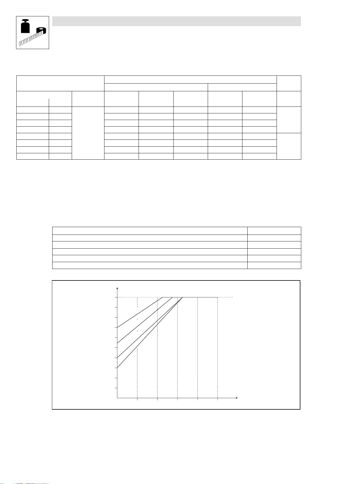
3.2.1 Operation with rated power (normal operation)
Typical motor power
Three−phase asynchronous motor
(4−pole)
8200 motec Type E82MV251_2B E82MV371_2B
Mains voltage U
Data for operation at 1/N/PE AC 230 V
Rated mains current I
Rated output current at
switching frequency
Max. permissible output
current for 60 s at
switching frequency
Output voltage UM [V] 3~ 0 ... U
Power loss (operation with IN8) Pv [W] 30 40
Dimensions L x W x H [mm] 190 x 138 x 100
Weight m [kg] 1.8 1.8
2 kHz
4 kHz
8 kHz IN8 [A] 1.7 2.4
16 kHz I
2 kHz
4 kHz
1)
8 kHz I
16 kHz I
Bold print = data for operation at a switching frequency of 8 kHz (Lenze setting)
1)
Currents for periodic load change: 1 min overcurrent time with I
2)
Under different operating conditions possible for some types: Operation with increased rated output current with the same load change
cycle ( 3−6)
PN [kW] 0.25 0.37
PN [hp] 0.34 0.5
[V] 1/N/PE AC 180 V − 0 % ... 264 V + 0 % ; 45 Hz − 0 % ... 65 Hz + 0 %
mains
[A] 3.4 5.0
mains
2)
I
[A]
N24
[A] 1.1 1.6
N16
I
[A] 2.5 3.6
max24
[A] 2.5 3.6
max8
[A] 1.6 1.4
max16
2.0 2.9
/ 0 ... 650 Hz
mains
and 2 min base load time with 75 % I
max
Nx
Fuses and cable cross−sections
8200 motec
Installation acc. to EN 60204−1 Installation acc. to UL
Type System Fuse Circuit breaker L1, L2, L3, PE Fuse L1, L2, L3, PE FI
[kW] [mm2] [AWG]
E82MV251_2B 0.25
E82MV371_2B 0.37 M10 A C10 A 1.5 10 A 16
1)
2)
Observe national and regional regulations
1/N/PE AC
180 ... 264 V;
45 ... 65 Hz
Only use UL−approved cables, fuses, and fuse holders.
UL fuse: voltage 240 V, tripping characteristic "H", "K5" or "CC"
Pulse current sensitive or universal−current sensitive earth−leakage circuit breaker
M10 A C10 A 1.5 10 A 16
Normal operation
1)
30 mA
2)
L
EDB82MV752 EN 5.2
3−5
Page 21
Technical data
Rated data at 230 V mains voltage
3.2.2 Operation with increased rated power
Under the application conditions described here the controller can be operated in continuous
operation with a motor of higher performance. The overload capacity is reduced to 120 %.
Typical applications:
– Pumps with quadratic load characteristic
– Fan
Operation is only permissible
– in the mains voltage ranges mentioned
– at a switching frequency of 2 or 4 kHz
– with the prescribed fuses and cable cross−sections
Typical motor power
Three−phase asynchronous motor
(4−pole)
8200 motec Type E82MV251_2B E82MV371_2B
Mains voltage U
Data for operation on 1/N/PE AC 230 V
Rated mains current I
Rated output current at
switching frequency
Max. permissible output
current for 60 s at
switching frequency
Output voltage UM [V] 3~ 0 ... U
Power loss (operation with I
Dimensions L x W x H [mm] 190 x 138 x 100
Weight m [kg] 1.8 1.8
2 kHz
4 kHz
2 kHz
4 kHz
1)
) Pv [W] 30 40
N24
1)
Currents for periodic load change with 1 min overcurrent time with I
PN [kW] 0.37 0.55
PN [hp] 0.5 0.75
[V] 1/N/PE AC 180 V − 0 % ... 264 V + 0 % ; 45 Hz − 0 % ... 65 Hz + 0 %
mains
[A] 4.1 6.0
mains
I
[A] 2.0 2.9
N24
I
[A] 2.5 3.6
max24
/ 0 ... 650 Hz
mains
and 2 min base load time with 75 % I
max
Nx
Fuses and cable cross−sections
8200 motec
Installation acc. to EN 60204−1 Installation acc. to UL
Type System Fuse Circuit breaker L1, L2, L3, PE Fuse L1, L2, L3, PE FI
[kW] [mm2] [AWG]
E82MV251_2B 0.37
E82MV371_2B 0.55 M10 A C10 A 1.5 10 A 16
1)
2)
Observe national and regional regulations
1/N/PE AC
180 ... 264 V;
45 ... 65 Hz
Only use UL−approved cables, fuses, and fuse holders.
UL fuse: voltage 240 V, tripping characteristic "H", "K5" or "CC"
Pulse current sensitive or universal−current sensitive earth−leakage circuit breaker
M10 A C10 A 1.5 10 A 16
Operation with increased rated power
1)
30 mA
2)
3−6
EDB82MV752 EN 5.2
L
Page 22
Technical data
Rated data at 400/500 V mains voltage
3.3 Rated data at a mains voltage of 400/500 V
3.3.1 Operation with rated power (normal operation)
Typical motor power
Three−phase asynchronous motor
(4−pole)
PN [kW] 0.55 0.75 1.5 2.2
PN [hp] 0.75 1.0 2.0 3.0
8200 motec Type E82MV551_4B E82MV751_4B E82MV152_4B E82MV222_4B
Mains voltage U
[V] 3/PE AC 320 V − 0 % ... 550 V + 0 % ; 45 Hz − 0 % ... 65Hz + 0 %
mains
Data for operation on 3/PE AC 400 V 500 V 400 V 500 V 400 V 500 V 400 V 500 V
Rated mains current I
Rated output current at
switching frequency
2 kHz
4 kHz
[A] 1.8 1.4 2.4 1.9 3.8 3.0 5.5 4.5
mains
2)
I
N24
[A]
2.1 1.8 2.9 2.4 4.6 3.9 6.7 5.6
8 kHz IN8 [A] 1.8 1.6 2.4 2.1 3.9 3.5 5.6 5.0
16 kHz I
Max. permissible output
current for 60 s at
switching frequency
1)
2 kHz
4 kHz
8 kHz I
16 kHz I
Output voltage UM [V] 3~ 0 ... U
[A] 1.2 1.1 1.6 1.4 2.5 2.3 3.6 3.2
N16
I
[A] 2.7 2.4 3.6 3.2 5.8 5.2 8.4 7.6
max24
[A] 2.7 2.4 3.6 3.2 5.8 5.2 8.4 7.6
max8
[A] 1.8 1.6 2.4 2.1 3.9 3.5 5.3 4.8
max16
mains
/ 0 ... 650 Hz
Power loss (operation with IN8) Pv [W] 35 45 70 95
Dimensions L x W x H [mm] 202 x 156 x 151 230 x 176 x 167
Weight m [kg] 2.8 2.8 4.1 4.1
Typical motor power
Three−phase asynchronous motor
(4−pole)
PN [kW] 3.0 4.0 5.5 7.5
PN [hp] 4.1 5.4 7.5 10.2
8200 motec Type E82MV302_4B E82MV402_4B E82MV552_4B E82MV752_4B
Mains voltage U
[V] 3/PE AC 320 V − 0 % ... 550 V + 0 % ; 45 Hz − 0 % ... 65Hz + 0 %
mains
Data for operation on 3/PE AC 400 V 500 V 400 V 500 V 400 V 500 V 400 V 500 V
Rated mains current I
Rated output current at
switching frequency
2 kHz
4 kHz
[A] 9.5 7.6 12.3 9.8 16.8 13.4 21.5 17.2
mains
2)
I
N24
[A]
8.8 7.0 11.4 9.2 15.6 12.5 16.5 13.2
8 kHz IN8 [A] 7.3 5.8 9.5 7.6 13.0 10.4 16.5 13.2
16 kHz I
Max. permissible output
current for 60 s at
switching frequency
1)
2 kHz
4 kHz
8 kHz I
16 kHz I
Output voltage UM [V] 3~ 0 ... U
[A] 4.7 4.2 6.1 5.5 8.4 7.6 10.7 9.6
N16
I
[A] 11.0 8.7 14.2 11.4 19.5 15.6 24.8 19.8
max24
[A] 11.0 8.7 14.2 11.4 19.5 15.6 24.8 19.8
max8
[A] 7.1 6.4 9.1 8.2 12.7 11.4 16.1 14.5
max16
mains
/ 0 ... 650 Hz
Power loss (operation with IN8) Pv [W] 14o 180 230 290
Dimensions L x W x H [mm] 325 x 211 x 163 (223**)
Weight m [kg] 9.7 9.7 9.7 9.7
Bold print = data for operation at a switching frequency of 8 kHz (Lenze setting)
1)
Currents for periodic load change: 1 min overcurrent time with I
2)
Under different operating conditions possible for some types: Operation with increases rated output current with the same load change
and 2 min base load time with 75 % I
max
Nx
cycle ( 3−9)
** for wall mounting or with a supplementary module (E82ZMV)
L
EDB82MV752 EN 5.2
3−7
Page 23
Technical data
Rated data at 400/500 V mains voltage
Fuses and cable cross−sections
8200 motec
Installation acc. to EN 60204−1 Installation acc. to UL
Normal operation
1)
Type System Fuse Circuit breaker L1, L2, L3, PE Fuse L1, L2, L3, PE FI
[kW] [mm2] [AWG]
E82MV551_4B 0.55
E82MV751_4B 0.75
E82MV152_4B 1.5
E82MV222_4B 2.2
E82MV302_4B 3.0
E82MV402_4B 4.0
E82MV552_4B 5.5
E82MV752_4B 7.5
1)
3/PE AC
320 ... 550 V;
45 ... 65 Hz
Only use UL−approved cables, fuses, and fuse holders.
M6 A B6 A 1 5 A 18
M6 A B6 A 1 5 A 18
M6 A B6 A 1 5 A 18
M10 A B10 A 1.5 10 A 16
M16 A B16 A 2.5 15 A 14
M20 A B20 A 4.0 20 A 12
M25 A B25 A 4.0 25 A 10
M32 A B32 A 6.0 35 A 8
30 mA
300 mA
UL fuse: voltage 500 ... 600 V, tripping characteristic "H", "K5" or "CC"
2)
Universal−current sensitive earth−leakage circuit breaker
Observe national and regional regulations
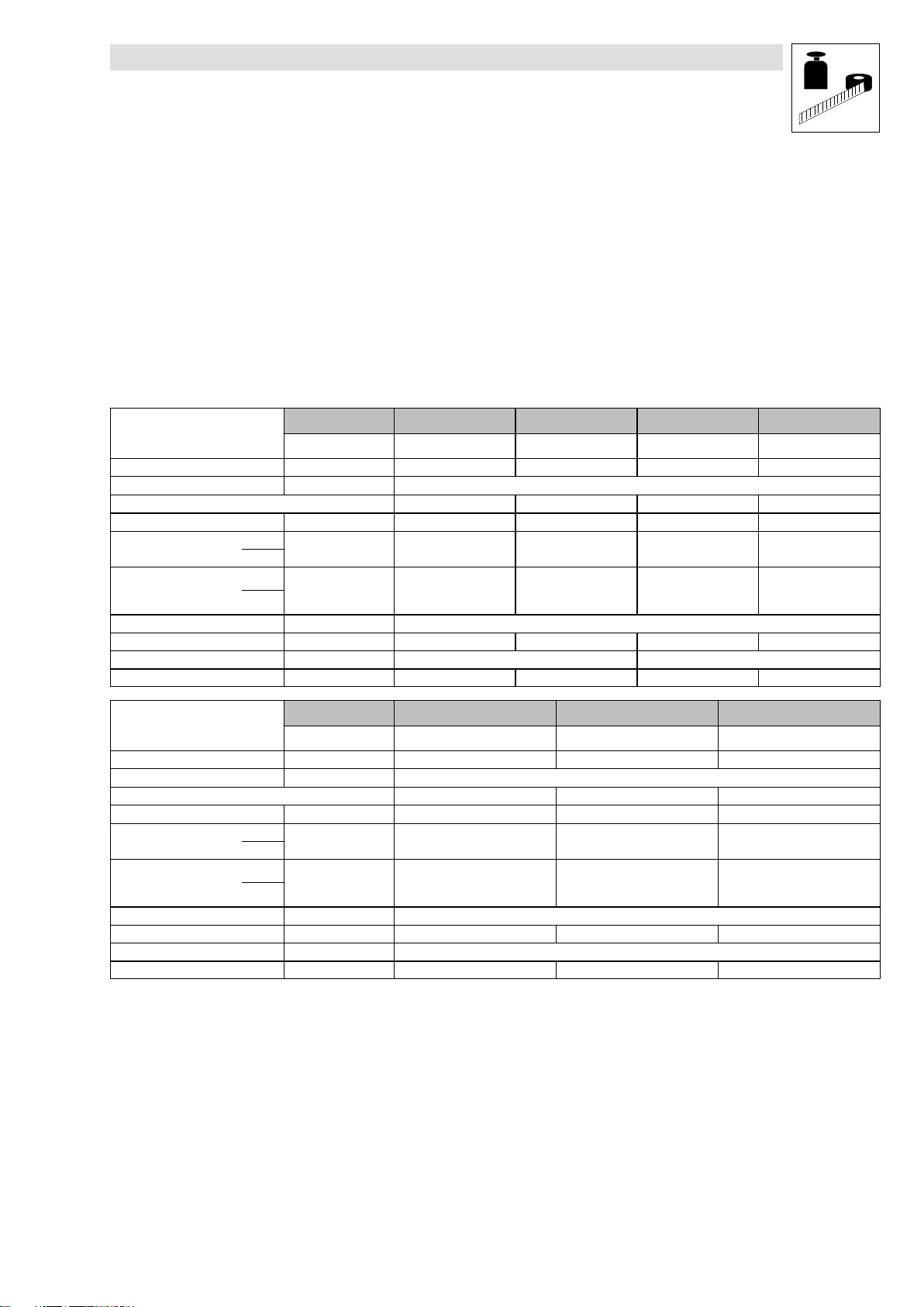
Current derating
Depending on the operating conditions and the use of the 8200 motec, the types E82MV302_4B to
EMV752_4B may require a reduction of the rated output current in continuous operation:
8200 motec mounted on... Current derating
...Lenze motor/forced ventilated geared motor not required
...Lenze motor/self−ventilated geared motor see illustration below
...Lenze motor/self−ventilated geared motor with E82ZMV supplementary module not required
...no Lenze motor/geared motor E82ZMV supplementary module is always required not required
...the wall (wall mounting) E82ZMV supplementary module is always required not required
2)
2)
I/I
N
1
0,9
0,8
0,7
0,6
0,5
0,4
0,3
0,2
E
E
0,1
B
4
_
2
0
3
V
M
2
8
B
4
_
2
0
4
V
M
2
8
B
4
_
2
5
5
B
V
4
M
_
2
2
8
5
E
7
V
M
2
8
E
10
20 30 40 50
f [Hz]
Fig. 3−1 Reduction of the rated output current in continuous operation at 40°C ambient temperature and a switching frequency of
4 kHz or 35°C and 8 kHz
I Reduced output current 8200 motec
I
N
f Output frequency 8200 motec [Hz]
Rated output current 8200 motec at a switching frequency of 4 kHz or 8 kHz
3−8
EDB82MV752 EN 5.2
L
Page 24
Technical data
Rated data at 400/500 V mains voltage
3.3.2 Operation with increased rated power
Under the application conditions described here the controller can be operated in continuous
operation with a motor of higher performance. The overload capacity is reduced to 120 %.
Typical applications:
– Pumps with quadratic load characteristic
– Fan
Operation is only permissible
– in the mains voltage ranges mentioned
– at a switching frequency of 2 or 4 kHz
– with the prescribed fuses and cable cross−sections
Typical motor power
Three−phase asynchronous motor
(4−pole)
8200 motec Type E82MV551_4B E82MV751_4B E82MV152_4B E82MV222_4B
Mains voltage U
Data for operation on 3/PE AC 400 V 400 V 400 V 400 V
Rated mains current I
Rated output current at
switching frequency
Max. permissible output
current for 60 s at
switching frequency
Output voltage UM [V] 3~ 0 ... U
Power loss (operation with IN8) Pv [W] 35 45 70 95
Dimensions L x W x H [mm] 202 x 156 x 151 230 x 176 x 167
Weight m [kg] 2.8 2.8 4.1 4.1
2 kHz
4 kHz
2 kHz
4 kHz
1)
PN [kW] 0.75 1.1 2.2 3.0
PN [hp] 1.0 1.5 3.0 4.0
[V] 3/PE AC 320 V − 0 % ... 440 V + 0 % ; 45 Hz − 0 % ... 65Hz + 0 %
mains
[A] 2.2 2.8 4.6 6.6
mains
I
[A] 2.1 2.9 4.6 6.7
N24
I
[A] 2.7 3.6 5.8 8.4
max24
/ 0 ... 650 Hz
mains
Typical motor power
Three−phase asynchronous motor
(4−pole)
8200 motec Type E82MV302_4B E82MV402_4B E82MV552_4B
Mains voltage U
Data for operation on 3/PE AC 400 V 400 V 400 V
Rated mains current I
Rated output current at
switching frequency
Max. permissible output
current for 60 s at
switching frequency
Output voltage UM [V] 3~ 0 ... U
Power loss (operation with IN8) Pv [W] 140 180 230
Dimensions L x W x H [mm] 325 x 211 x 163 (223**)
Weight m [kg] 9.7 9.7 9.7
2 kHz
4 kHz
2 kHz
4 kHz
1)
Bold print = data for operation at a switching frequency of 8 kHz (Lenze setting)
1)
Currents for periodic load change with 1 min overcurrent time with I
** for wall mounting or with a supplementary module (E82ZMV)
PN [kW] 4 5.5 7.5
PN [hp] 5.4 7.5 10.2
[V] 3/PE AC 320 V − 0 % ... 440 V + 0 % ; 45 Hz − 0 % ... 65Hz + 0 %
mains
[A] 11.4 14.8 20.2
mains
I
[A] 8.8 11.4 15.6
N24
I
[A] 11.0 14.2 19.5
max24
/ 0 ... 650 Hz
mains
and 2 min base load time with 75 % I
max
Nx
L
EDB82MV752 EN 5.2
3−9
Page 25
Technical data
Rated data at 400/500 V mains voltage
Fuses and cable cross−sections
8200 motec
Installation acc. to EN 60204−1 Installation acc. to UL
Operation with increased rated power
1)
Type System Fuse Circuit breaker L1, L2, L3, PE Fuse L1, L2, L3, PE FI
[kW] [mm2] [AWG]
E82MV551_4B 0.75
E82MV751_4B 1.1
E82MV152_4B 2.2
E82MV222_4B 3.0
E82MV302_4B 4.0
E82MV402_4B 5.5
E82MV552_4B 7.5
1)
3/PE AC
320 ... 440 V;
45 ... 65 Hz
Only use UL−approved cables, fuses, and fuse holders.
M6 A B6 A 1 5 A 18
M6 A B6 A 1 5 A 18
M10 A B10 A 1.5 10 A 16
M10 A B10 A 1.5 10 A 16
M16 A B16 A 2.5 15 A 14
M20 A B20 A 4.0 20 A 12
M32 A B32 A 6.0 25 A 10
30 mA
300 mA
UL fuse: voltage 500 ... 600 V, tripping characteristic "H", "K5" or "CC"
2)
Universal−current sensitive earth−leakage circuit breaker
Observe national and regional regulations
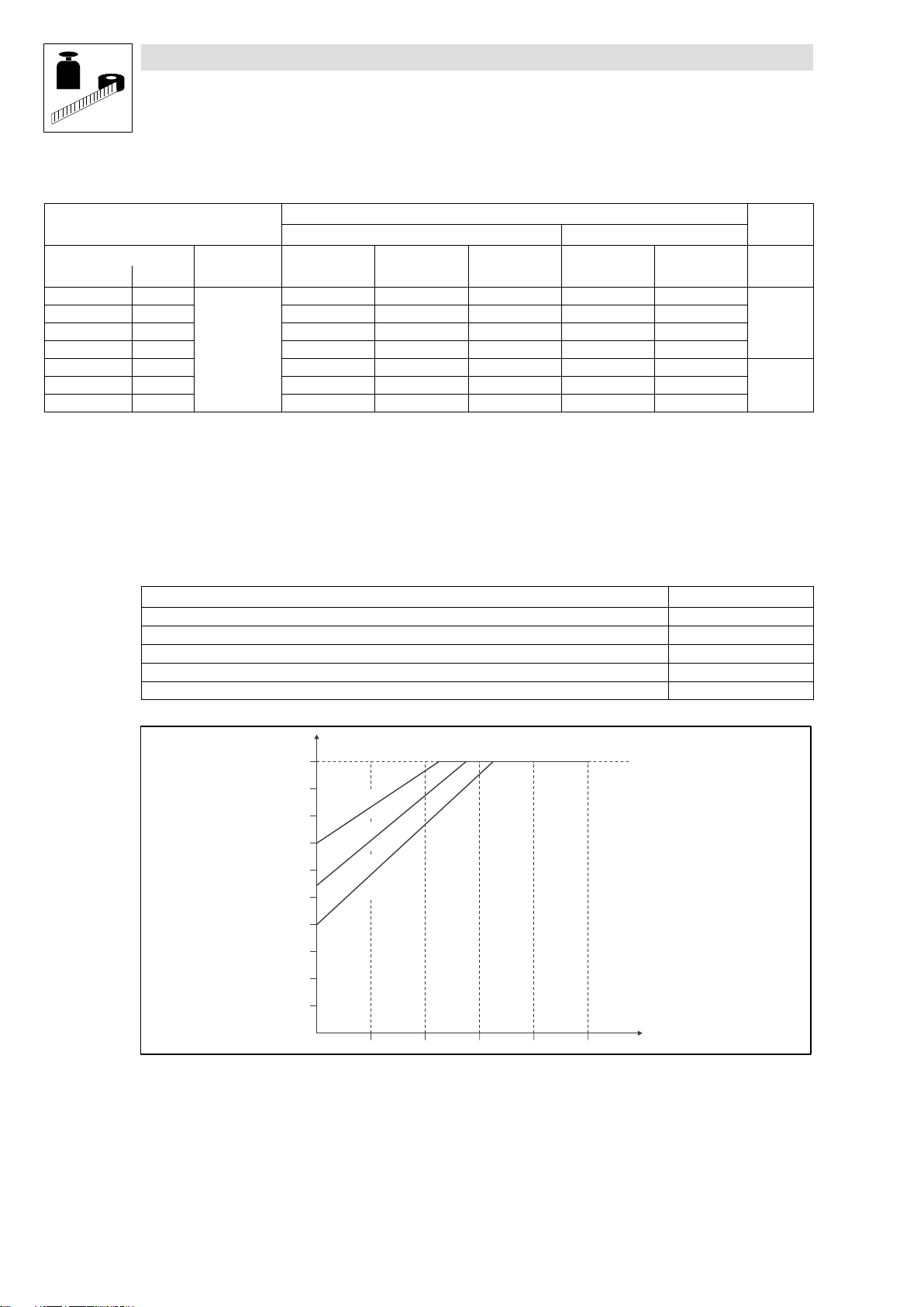
Current derating
Depending on the operating conditions and the use of the 8200 motec, the types E82MV302_4B to
EMV552_4B may require a reduction of the rated output current in continuous operation:
8200 motec mounted on... Current derating
...Lenze motor/forced ventilated geared motor not required
...Lenze motor/self−ventilated geared motor see illustration below
...Lenze motor/self−ventilated geared motor with E82ZMV supplementary module not required
...no Lenze motor/geared motor E82ZMV supplementary module is always required not required
...the wall (wall mounting) E82ZMV supplementary module is always required not required
2)
2)
I/I
N
1
0,9
0,8
0,7
0,6
0,5
0,4
0,3
0,2
E
E
0,1
B
4
_
2
0
3
V
M
2
8
B
4
_
2
0
4
V
M
2
8
B
4
_
2
5
5
V
M
2
8
E
10
20 30 40 50
f [Hz]
Fig. 3−2 Reduction of the rated output current in continuous operation at 40°C ambient temperature and a switching frequency of
4 kHz
I Reduced output current 8200 motec
I
N
f Output frequency 8200 motec [Hz]
Rated output current 8200 motec at a switching frequency of 4 kHz
3−10
EDB82MV752 EN 5.2
L
Page 26

4 Installation
4.1 Mechanical installation
4.1.1 Important notes
The 8200 motec frequency inverter can be used in all operating positions.
Free space:
– Allow a free space of 100 mm above and below the inverter.
– Ensure unimpeded ventilation of cooling air and outlet of exhaust air.
Tip!
The installation of compact drives, mechanical motor mounting or wall mounting is described in the
corresponding Mounting Instructions.
Installation
Mechanical installation − Important notes
4.1.2 Mechanical design
Type Cable connections Weight
E82MV251_2B
E82MV371_2B
E82MV551_4B
E82MV751_4B
E82MV152_4B
E82MV222_4B
E82MV302_4B
E82MV402_4B
E82MV552_4B
E82MV752_4B
4 M20
2 M16
2 M25
4 M16
1 M20 for motor cable used for wall mounting (EMC cable connection)
1 M20
2 M25
4 M16
1 M20 for motor cable used for wall mounting (EMC cable connection)
3 M25
4 M16
(thread length 10 mm, without counter nut) 1.8 kg
(thread length 10 mm, without counter nut)
2.8 kg
(thread length 10 mm, with counter nut)
(thread length 10 mm, without counter nut)
4.1 kg
(thread length 10 mm, with counter nut)
(thread length 10 mm, without counter nut) 9.7 kg
L EDB82MV752 EN 5.2
4−1
Page 27
Installation
Mechanical installation − Dimensions
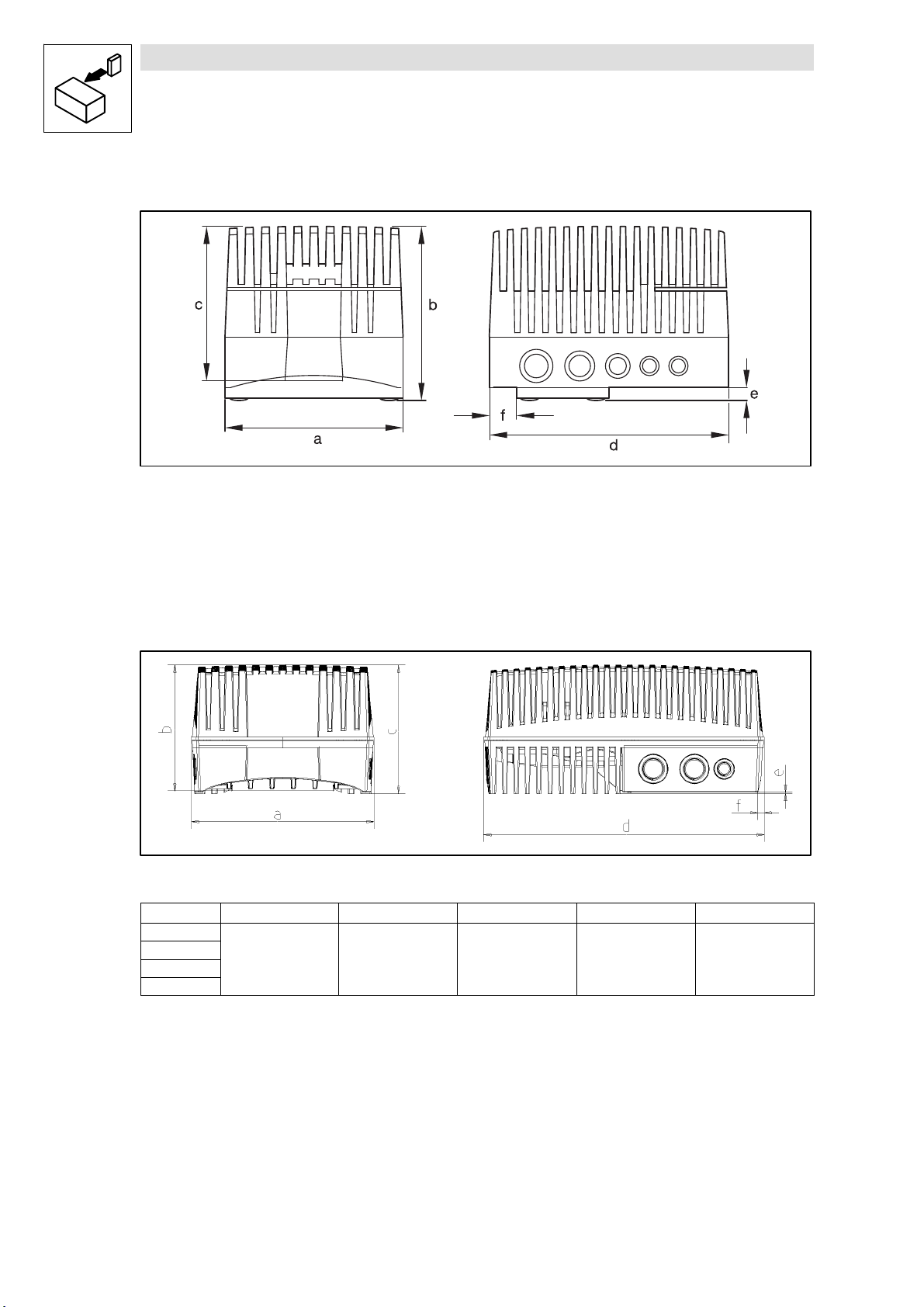
4.1.3 Dimensions
Fig. 4−1 Dimensions 0.25 ... 2.2 kW
E82MV251_2B
E82MV371_2B
E82EV551_4B
E82EV751_4B
E82EV152_4B
E82EV222_4B
8200mot001
a [mm] b [mm] c [mm] d [mm] [mm] f [mm]
138 100 90 190 7 12
156 151 135 202 15 26
176 167 151 230 15 26
Fig. 4−2 Dimensions 3 ... 7.5 kW
Type a [mm] b [mm] c [mm] d [mm] [mm]
E82MV302_4B
E82MV402_4B
E82MV552_4B
E82MV752_4B
**
for wall mounting or with fan module (type E82ZMV, dimensions L x W x H [mm]: 325 x 211 x 60), see also Instructions enclosed in the fan
module.
4−2
211 163 (223**) 148 325 15
EDB82MV752 EN 5.2
82mot443
L
Page 28
4.2 Electrical installation
4.2.1 Important notes
Stop !
The controller contains electrostatic sensitive devices!
Before working in the connection area, the personnel must be free of electrostatic charges.
4.2.1.1 Protection of persons
Danger!
Before working on the controller, check whether all power terminals (device version 001 or 151) and
the pins of the FIF interface are dead, because
the power terminals U, V, W, BR0, BR1, BR2 and the pins of the FIF interface remain live for at
least 1 minute after power−off.
the power terminals L1, L2, L3; U, V, W, BR0, BR1, BR2 and the pins of the FIF interface
remain live when the motor is stopped.
the relay outputs K11, K12, K14 (device version 001 or 151) can be live if the controller is
disconnected from the mains.
Installation
Electrical installation − Important notes
Use of earth−leakage circuit breakers ( 4−5)
Pluggable terminal strips
Plug in or pull off all pluggable terminals in deenergised state only!
Replacing defective fuses
Replace defective fuses with the prescribed type only when no voltage is applied.
Disconnecting the controller from the mains
The controller can be safely disconnected from the mains only via a contactor on the input side.
4.2.1.2 Motor protection
Extensive protection against overload:
– By overcurrent relay or temperature monitoring.
– We recommend to use PTC thermistors or thermal contacts for motor temperature
monitoring. (Lenze three−phase AC motors are equipped with thermal contacts (NC
contacts) as standard)
– PTC thermistors or thermal contacts can be connected to the controller.
Only use motors the insulation of which is suitable for inverter operation:
– Insulation resistance: min. û = 1.5 kV, min. du/dt = 5 kV/μs
– Lenze three−phase AC motors are designed for inverter operation.
– When using motors with an unknown insulation resistance, please contact your motor
supplier.
L
EDB82MV752 EN 5.2
4−3
Page 29

Installation
Electrical installation − Important notes
4.2.1.3 Mains types/mains conditions
Please observe the restrictions of each mains type!
System Controller operation Notes
with earthed neutral
(TT/TN systems)
with isolated neutral
(IT systems)
4.2.1.4 Operation on public supply systems (compliance with EN 61000−3−2)
The European standard EN 61000−3−2 stipulates limit values for harmonic currents in the supply
system. Non−linear consumers (e.g. frequency inverters) cause harmonic currents which "interfere"
the supplying mains and may disturb other consumers. This standard helps to ensure the high quality
of public mains systems and reduce the mains load.
No restrictions Comply with the rated data of the
possible if the controller is protected in the event of an earth fault in the
mains supply
by suitable equipment which detect the earth fault and
the controller is directly disconnected from the mains
controllers.
In the event of an earth fault at the
inverter output, a safe operation
cannot be ensured.
Tip!
The standard only applies to public mains systems. Mains systems with an own transformer station
as common in industry are not public. Thus, the standard does not apply to them.
If a device or machine consists of several components, the limit values defined in the standard apply
to the entire unit.
If you observe all measures given, the controllers comply with the limit values according to
EN 61000−3−2. The machine/system manufacturer is responsible for the compliance with the
requirements for the machine/system:
Supply voltage Power Measure
8200 motec [V] [kW]
E82MV251_2B
E82MV371_2B 0.37
E82MV551_4B
E82MV751_4B 0.75
1/N/PE AC 230 V
3/PE AC 400 V
0.25
0.55
Use ELN1−0900H005 mains choke
Use EZN3A1500H003 mains choke
4−4
EDB82MV752 EN 5.2
L
Page 30

Electrical installation − Important notes
4.2.1.5 Operation with earth−leakage circuit breaker
Danger!
The controllers have an internal mains rectifier. In the event of a short circuit to frame, a DC residual
current can prevent the activation of the AC−sensitive or pulse−current sensitive earth−leakage circuit
breakers and thus block the protective function for all electrical equipment operated on this
earth−leakage circuit breaker.
We recommend the following to protect persons and animals (DIN VDE 0100):
– Pulse current sensitive earth−leakage circuit breakers in systems where controllers are
connected to a single−phase mains (L1/N).
– Universal−current sensitive earth−leakage circuit breakers in systems where controllers are
connected to a three−phase mains (L1/L2/L3).
Earth−leakage circuit breakers must only be installed between mains supply and controller.
Earth−leakage circuit breakers can be misactivated by
– capacitive compensation currents of the cable shields during operation (especially with long,
shielded motor cables),
– simultaneous connection of several controllers to the mains,
– use of additional interference filters.
Installation
4.2.1.6 Interaction with compensation equipment
Controllers only consume very little reactive power of the fundamental wave from the
AC mains. Therefore, a compensation is not necessary.
If you operate the controllers on a mains with compensation equipment, the compensation
equipment must be provided with chokes.
– For this purpose please contact the supplier of the compensation equipment.
L
EDB82MV752 EN 5.2
4−5
Page 31

Installation
Electrical installation − Important notes
4.2.1.7 Specification of the cables used
Power terminals
The cables used must comply with the approvals required for the application (e.g. UL).
Use low−capacitance motor cables. Capacitance per unit length:
– Core/core 75 pF/m
– Core/shield 150 pF/m
Max. permissible motor cable length without external measures:
– unshielded: 10 m
– shielded: 10 m
Control connections
Control cables must always be shielded to prevent interference injections.
Shielded cables
The efficiency of shielded cables is determined by
a good shield connection
– a contact surface as large as possible.
a low shield resistance:
– only use shields with tin or nickel−plated copper braid!
– shields made of steel braid are not suitable.
the overlap rate of the braid:
– at least 70 to 80 % with an overlap angle of 90°.
4−6
EDB82MV752 EN 5.2
L
Page 32

Electrical installation − Installation according to EMC requirements
4.2.2 Installation according to EMC
The electromagnetic compatibility (EMC) of a machine depends on the type of installation and the
care taken.
If you observe the following measures, you can assume that the machine will operate without any
EMC problems caused by the drive system.
4.2.2.1 Assembly
Ensure the separation of motor cable and signal or mains cables.
Do not use the same terminal strip for mains input and motor output.
Rout cables as close as possible to the reference potential. Freely suspended cables have the
same effect as aerials.
4.2.2.2 Filters
Only use RFI filters and mains chokes which are assigned to the controllers:
– RFI filters reduce impermissible high−frequency interferences to a permissible value.
– Mains chokes reduce the effective current consumption of the frequency inverter on the
mains.
Installation
4.2.2.3 Shielding
Use shielded, low−capacitance motor cable. Capacitance per unit length:
– Core/core 75 pF/m
– Core/shield 150 pF/m
Connect the shield to the shield sheets in the motec with a large surface
Connect the shield with PE in the terminal box of the motor:
– Metal cable glands at the motor terminal box ensure a large surface connection of the shield
to the motor housing.
If you use a brake resistor:
– Connect the shield of the brake resistor cable directly at the frequency inverter and the
brake resistor to the mounting plate with a large surface.
Shield control cables:
– Connect control cable shields at both ends.
4.2.2.4 Earthing
Earth all components (controllers, RFI filters, motor filters, mains chokes) using suitable cables
connected to a central earthing point (PE rail).
Maintain the defined minimum cross−sections:
– For EMC, the surface of the cable with a large−surface contact is decisive, i.e. as large
cross−sections as possible (large surface).
L
EDB82MV752 EN 5.2
4−7
Page 33

Installation
Electrical installation − Connections
4.2.3 Power connections
See corresponding Mounting Instructions
4.2.4 Control connections
The basic controller version is not provided with control terminals. Different I/O function modules are
available for the FIF interface to equip the controllers with control terminals.
4.2.4.1 Mounting/dismounting the I/O function module
See corresponding Mounting Instructions
4−8
EDB82MV752 EN 5.2
L
Page 34

Installation
Electrical installation − Connections
4.2.4.2 Terminal assignment − standard I/O E82ZAFSC001
Stop !
Control cables must always be shielded to prevent interference injections!
Electrical connection Terminal strip with screw connection
Possible connections
Tightening torque 0.22 ... 0.25 Nm (1.9 ... 2.2 lb−in)
Bare end 5 mm
rigid: 1.5 mm
flexible:
without wire end ferrule
2
1.0 mm
(AWG 18)
with wire end ferrule, without plastic sleeve
2
0.5 mm
(AWG 20)
with wire end ferrule, with plastic sleeve
2
0.5 mm
(AWG 20)
2
(AWG 16)
L
EDB82MV752 EN 5.2
4−9
Page 35

Installation
Electrical installation − Connections
Supply via the internal voltage source (X3/20):
X3/28, controller inhibit (CINH)
X3/E1 .... X3/E4, digital inputs
GND2
X3
GND1
62 8
AOUT1
GND1
+5V
0…+5V
+20V
20 28
9
897
1k … 10k
77
AIN1
E1 E2E3E439A1
Supply via an external voltage source:
X3/28, controller inhibit (CINH)
X3/E1 ... X3/E4, digital inputs
GND1
GND1
+20V
+5V
6278 9 20 28E1E2 E3 E4 39 A1 59
X3
AOUT1
7
AIN1
7
8
9
1k … 10k
0…+5V
59
DIGOUT1
GND2
DIGOUT1
_
+
24 V ext.
(+12VDC-0%
...
+30VDC+0%,
max. 120 mA)
E82ZAFS004
E82ZAFS005
Min. wiring required for operation
Signal type and range selection by DIP switch
ON
1ON234
5
OFF
) Note!
DIP switch and C0034 must be set for the same value range, otherwise the analog
input signal at X3/8 will be interpreted incorrectly by the basic unit.
If a setpoint potentiometer is internally supplied through X3/9, the DIP switch must
be set for a voltage range of 0 ... 5 V. Otherwise it is not possible to use the whole
speed range.
−3− Switch position
Signal at X3/8 1 2 3 4 5 C0034
0 ... 5 V OFF OFF ON OFF OFF 0
0 ... 10 V (Lenze setting) OFF OFF ON OFF ON 0
0 ... 20 mA OFF OFF ON ON OFF 0
4 ... 20 mA OFF OFF ON ON OFF 1
4 ... 20 mA Open−circuit monitoring OFF OFF ON ON OFF 3
−10 V ... +10 V ON ON OFF OFF OFF 2
4−10
EDB82MV752 EN 5.2
L
Page 36

Installation
Electrical installation − Connections
X3/ −4− Signal type Function Level
62 Analog output Output frequency 0 ... + 6 V
7 − GND1, reference potential for analog signals −
8 Analog input
Act. or setpoint input
Change range using the DIP switch and C0034
Lenze setting: Bold print
0 ... + 10 V
1)
Master voltage 0 ... +5 V
0 ... +10 V
−10 V ... +10 V
2)
Master current 0 ... +20 mA
+4 ... +20 mA
+4 ... +20 mA (open−circuit monitored)
9 − Internal, stabilised DC voltage supply for setpoint potentiometer +5.2 V
20 − Internal DC voltage supply for control of digital inputs and outputs +20 V 10 % (ref.: X3/7)
28
3)
E1
3)
E2
Digital inputs
E3 DC−injection brake (DCB) 1 = DCB
E4 Change of direction of rotation
39 − GND2, reference potential for digital signals −
A1
Digital output
59 − DC supply for X3/A1
Controller inhibit (CINH) 1 = START
Activation of JOG frequencies
JOG1 = 20 Hz
JOG2 = 30 Hz
JOG3 = 40 Hz
CW/CCW rotation
Ready for operation with
– internal supply:
– external supply:
– internal (bridge to X3/20):
– external:
JOG1 1 0
JOG2 0 1
JOG3 1 1
CW 0
CCW 1
0 ... +20 V
0 ... +24 V
+20 V
+24 V
E1 E2
E4
1)
Output level 0 ... + 10 V: Adapt offset (C0109/C0422) and gain (C0108/C0420)
2)
Adjust offset (C0026) and gain (C0027) separately for each function module:
After replacing the function module or the basic device
After loading the Lenze setting
3)
Alternatively frequency input 0 ... 10 kHz single−tracked or 0 ...1 kHz double−tracked, configuration via C0425
L
EDB82MV752 EN 5.2
4−11
Page 37

Installation
Electrical installation − Connections
4.2.4.3 Terminal assignment − application I/O E82ZAFAC001
Stop !
Control cables must always be shielded to prevent interference injections!
Electrical connection Terminal strip with screw connection
Possible connections
Tightening torque 0.22 ... 0.25 Nm (1.9 ... 2.2 lb−in)
Bare end 5 mm
rigid: 1.5 mm
flexible:
without wire end ferrule
2
1.0 mm
(AWG 18)
with wire end ferrule, without plastic sleeve
2
0.5 mm
(AWG 20)
with wire end ferrule, with plastic sleeve
2
0.5 mm
(AWG 20)
2
(AWG 16)
4−12
EDB82MV752 EN 5.2
L
Page 38

Electrical installation − Connections
Controller inhibit (CINH) supply via internal voltage source (X3.3/20)
1U
9
2U1U2I 62 63
1I
X3.1
7
AIN2 AOUT2AIN1 AOUT1
GND
GND
A2A1 7 7 A4 20 28E1E2 E3 E4 E5 E6
X3.3
DIGOUT2 DFOUT1DIGOUT1
59
+20 V
0…+5V
1k … 10k
X3.2
Controller inhibit (CINH) supply via external voltage source
1U
9
2U1U2I 62 63
1I
X3.1
0 … +5 V
1k … 10k
7
AIN2 AOUT2AIN1 AOUT1
X3.2
+5 V
9
+5 V
9
Installation
E82ZAFA001
GND
GND
A2A1 7 7 A4 20 28E1E2 E3 E4 E5 E6
X3.3
DIGOUT2 DFOUT1DIGOUT1
(+12VDC-0% ... +30VDC+0%,
59
_
+
24 V ext.
max. 200 mA)
+20 V
E82ZAFA002
Min. wiring required for operation
L
EDB82MV752 EN 5.2
4−13
Page 39

Installation
Electrical installation − Connections
Jumper setting for inputs
5
7
3
6
214
) Note!
If a setpoint potentiometer is internally supplied via X3.2/9, the jumper must be set
to a voltage range between 0 ... 5 V. Otherwise not the whole speed range can be
covered.
X3.1/1U
Analog input1, AIN1
X3.1/2U
Analog input2, AIN2
X3.1/1I
Analog input1, AIN1
X3.1/2I
Analog input2, AIN2
Lenze setting (see bold print in tables)
1 − 3
2 − 4
7 − 9
1098
Possible levels
Jumper 7 − 9: free 7 − 9 7 − 9
Code C0034/1 = 0 C0034/1 = 0 C0034/1 = 1
Possible levels
Jumper 8 − 10: free 8 − 10 8 − 10
Code C0034/2 = 0 C0034/2 = 0 C0034/2 = 1
Possible levels
Jumper any any any
Code C0034/1 = 2 C0034/1 = 3 C0034/1 = 4
Possible levels
Jumper any any any
Code C0034/2 = 2 C0034/2 = 3 C0034/2 = 4
8 − 10
0 ... 5 V 0 ... 10 V
0 ... 5 V 0 ... 10 V
0 ... 20 mA 4 ... 20 mA 4 ... 20 mA
0 ... 20 mA 4 ... 20 mA 4 ... 20 mA
2)
2)
−10 V ... +10 V
−10 V ... +10 V
1)
1)
1)
open−circuit monitored
2)
Lenze setting (delivery status)
4−14
EDB82MV752 EN 5.2
L
Page 40

Jumper setting for outputs
Installation
Electrical installation − Connections
5
7
3
1098
j6
214
X3.1/62
Analog output, AOUT1
X3.1/63
Analog output, AOUT2
X3.1/ −5− Signal type Function Level
1U/2U Analog inputs Actual or setpoint inputs (master voltage)
1I/2I Actual or setpoint inputs (master current)
X3.2/ −6− Signal type Function
62
63 Motor current
9 − Internal, stabilised DC voltage supply for setpoint potentiometer +5.2 V
Analog outputs
Possible levels
Jumper 1 − 3 3 − 5 3 − 5
Code C0424/1 = 0 C0424/1 = 0 C0424/1 = 1
Possible levels
Jumper 2 − 4 4 − 6 4 − 6
Code C0424/2 = 0 C0424/2 = 0 C0424/2 = 1
Use jumper and C0034 to change range
Use jumper and C0034 to change range
(Lenze setting, in bold print)
Output frequency
Lenze setting (see bold print in tables)
1 − 3
2 − 4
7 − 9
8 − 10
0 ... 10 V 0 ... 20 mA 4 ... 20 mA
0 ... 10 V 0 ... 20 mA 4 ... 20 mA
(Lenze setting, in bold print)
0 ... +5 V
0 ... +10 V
−10 V ... +10 V
0 ... +20 mA
+4 ... +20 mA
+4 ... +20 mA (open−circuit monitored)
Level
(Lenze setting, in bold print)
Voltage output:
0 ... +6 V
0 ... +10 V
Current output:
(0 ... +12 mA)
0 ... +20 mA
+4 ... +20 mA
1)
1)
1)
1)
Output level 0 ... + 10 V or 0/+4 ... +20 mA: Adapt offset (C0422) and gain (C0420)
L
EDB82MV752 EN 5.2
4−15
Page 41

Installation
Electrical installation − Connections
X3.3/ −6− Signal type Function Level
A1
A2 not prefabricated
7 − GND, reference potential −
A4 Frequency
59 − DC supply for X3/A1 and X3/A2
20 − Internal DC voltage supply for control of digital inputs and output +20 V 10 %
28
2)
E1
2)
E2
E3 DC−injection brake (DCB) 1 = DCB
E4 Change of direction of rotation
E5 not prefabricated −
E6 not prefabricated −
2)
Digital outputs
output
Digital inputs
Optional frequency input 0 ... 102.4 kHz, single−tracked or double−tracked, configuration via C0425
Ready for operation
DC bus voltage HIGH:
Controller inhibit (CINH) 1 = START
Activation of JOG frequencies
JOG1 = 20 Hz
JOG2 = 30 Hz
JOG3 = 40 Hz
CW/CCW rotation
(Lenze setting, in bold print)
0/+20 V at DC internal
0/+24 V at DC external
+18 V...+24 V (HTL)
LOW: 0 V
+20 V (internal, bridge to X3/20)
+24 V (external)
JOG1 1 0
JOG2 0 1
JOG3 1 1
CW 0
CCW 1
E1 E2
E4
4.2.4.4 Wiring of bus function modules
System bus (CAN): see CAN Communication Manual
For all other bus function modules (e.g. PROFIBUS−DP, INTERBUS, ...) see the accompanying
Mounting Instructions or Communication Manual.
4−16
EDB82MV752 EN 5.2
L
Page 42

5 Commissioning
5.1 Before you start
Tip!
The controller is factory−set to drive the following four−pole standard asynchronous motors:
– 230/400 V, 50 Hz
– 280/480 V, 60 Hz
– 400 V, 50 Hz
Maintain the switch−on sequence. ( 5−6)
In the event of an error during commissioning please see the "Troubleshooting and fault
elimination" chapter: ( 8−1)
Commissioning
Before you start
Check ...
... before the mains voltage is connected
the wiring for completeness, short circuit, and earth fault
If no function module is used (delivery status):
– Has the FIF cover been mounted?
If the internal voltage source X3/20 of the standard I/O is used:
– Are the terminals X3/7 and X3/39 bridged?
... the most important drive parameters settings before the controller is enabled
Has the V/f rated frequency been adapted to the motor circuit configuration? ( 7−5)
Have the configuration of the analog inputs and outputs been adapted to the wiring? ( 7−57)
Have the configuration of the digital inputs and outputs been adapted to the wiring? ( 7−68)
Are the drive parameters relevant for your application set correctly?
If required, use the keypad or PC to adapt them. ( 6−1 ff)
5.2 Before switching on
( STOP!
Special commissioning procedure after long−time storage
If controllers have been stored for more than 2 years, their DC−bus capacitors may
have dried out.
Possible consequences:
l The DC−bus capacitors and thus the controller will be damaged at the first
switch−on.
Protective measures:
l Anodize the DC−bus capacitors before commissioning. A detailed set of
instructions can be downloaded from the Internet (www.Lenze.com).
L EDB82MV752 EN 5.2
5−1
Page 43

Commissioning
Parameter setting using the keypad
5.2.1 Menu structure
For easy operation the codes are divided in two groups:
The user menu
– is active after every mains switching or keypad attachment during operation.
– contains all codes for a standard application with linear V/f characteristic control (Lenze
setting).
– can be modified as required under C0517.
The all menu
– contains all codes.
– shows a list of all codes in ascending order.
j gfkih PS
qr
Hi
1
Lo
xx
j
mno
qr
Hi
Lo
user
j
mno
qr
Hi
j
gfkih PS
Lo
mno
qr
Hi
Lo
~5 s
j
gfkihPS
mno
p
qr
Hi
Lo
000
5
z
wx
y
x
bcd e
0050
vtu
a
000
Hz
s
a
bcd e
o
0050
suer
…
o
t
bcd e
gfkih PS
p
0XXX 000X
000
bcd e
gfkih PS
p
0XYZ
bcd e
000
p
0ZXY
000
a
000
t
a
000
a
1
000
1
C517/3
1
000
Hz
1
C517/1
C517/2
z
y
j
mno
qr
Hi
Lo
j gfkih PS
qr
Hi
Lo
xx
Hi
Lo
j
mno
qr
Hi
gfkih PS
Lo
bcd e
o
p
0050
AL L
…
o
t
bcd e
j
gfkih PS
mno
p
qr
000
ALL
bcd e
gfkih PS
p
0XYZ
bcd e
000
p
0ZXY
000
a
000
000
1
a
1
000
Hz
t
a
1
000
C000x
Hz
a
1
C000x+1
C000x+2
mno
qr
Hi
Lo
p
0UVW
000
000
1
C517/10
a
bcd e
j
gfkih PS
Fig. 5−1 Change between the uSEr and ALL menus
j
gfkih PS
mno
qr
Hi
Lo
000
bcd e
p
0UVW
000
a
1
C000x+n
8200vec075
5−2
EDB82MV752 EN 5.2
L
Page 44

5.2.2 Changing and saving parameters
) Note!
l The user menu user is active after mains switching. Change to the menu all to
address all codes.
l In the different parameter sets only parameter values can be changed with the
keypad.
l Digital signals must be used to activate a parameter set for operation
(configuration with C0410)!
l In the function the display shows the parameter set which is just active
during operation.
Step Keys Result Action
1. Connect keypad
2. If necessary change to
the menu "ALL"
3.
4.
5.
6. Select parameter set for
change
7.
8.
9.
10. Inhibit controller
11. Set parameters
12.
13.
14.
15.
16.
17.
18. Restart the "loop" at 11. or 6. to set other parameters.
XXXX
XXX
XXXXX
STOre
xx.xx Hz
Change to function bar 2
all Select menu "ALL" (list of all codes)
Confirm selection and change to function bar 1
Change to function bar 2
1 ... 4 Select parameter set to be changed
Confirm selection and change to function bar 1
001
Commissioning
Parameter setting using the keypad
Function is activated. The first code in the user menu will be
displayed (C0517/1, Lenze setting: C0050 = output frequency).
Only necessary if you want to change C0002, C0148, C0174 and/or
C0469
Select code
For codes without subcodes: Jump automatically to
Select subcode
Set parameters
Confirm entry if is blinking
Confirm entry if is not blinking; is not active
L EDB82MV752 EN 5.2
5−3
Page 45

Commissioning
Selection of the correct control mode
5.3 Selection of the correct control mode
The following table helps you to find the correct control mode for standard applications. You can
choose between V/f characteristic control, vector control and sensor torque control:
V/f characteristic control is the classic control mode for standard applications.
The vector control provides better control features than the V/f characteristic control because of:
a higher torque over the whole speed range
higher speed accuracy and smooth running features
higher efficiency
V/f characteristic control
Vector control
Tip!
The parameters for the corresponding control mode are to be set as follows:
for linear V/f characteristic control in menu USEr
for square−law V/f characteristic control, vector control or sensorless torque in menu ALL
5−4
EDB82MV752 EN 5.2
L
Page 46

Commissioning
Selection of the correct control mode
Application Operating mode
C0014
Stand−alone drives
with extremely alternating loads −4− −2−
with heavy start conditions −4− −2−
with speed control (speed feedback) −2− −4−
with high dynamic response (e. g. positioning and infeed drives) −2− −
with torque setpoint −5− −
with torque limitation (power control) −2− −4−
three−phase AC reluctance motors −2− −
three−phase sliding rotor motors −2− −
three−phase motors with fixed frequency−voltage characteristic −2− −
Pump and fan drives with square−law load characteristic −3− −2− / −4−
Group drives
(several motors connected to controller)
identical motors and identical loads −2− −
different motors and/or changing loads −2− −
C0014 = −2−: linear V/f characteristic control
C0014 = −3−: square−law V/f characteristic control
C0014 = −4−: vector control
C0014 = −5−: sensorless torque control
recommended alternatively
L
EDB82MV752 EN 5.2
5−5
Page 47

Commissioning
V/f characteristic control
5.4 Commissioning − V/f characteristic control
5.4.1 Commissioning without function module
Stop !
The controller can only be used when the FIF cover is mounted!
– If the FIF cover is missing, the green LED is blinking (keypad: ). The controller is
inhibited.
– The FIF cover is mounted when the inverter is delivered.
Since the controller is not provided with control terminals when the function module is not
attached, starting and stopping during operation is also possible by switching the mains.
– Frequent mains switching (e.g. inching mode via mains contactor) may overload and destroy
the input current limitation of the controller: for this reason, at least three minutes have to
pass between two starting operations.
The function saves the setpoint at the time the operation is interrupted when switching the
mains or in case of mains failures. The drive restarts automatically as soon as the mains
recovers.
If the drive does not start after the setpoint has been selected, ( does not go off), press
to enable the controller.
a
8
888
m
Hz
AV
W
%sh
°C
rpm
s
vtu
8200mot170
E82ZBB
bcde
j
gfkihPS
mno
p
qr
8888
Hi
Lo
88888
z
wx
y
E82ZWLxxx
1
AIF
L1/L2/L3/PE
W
V
U
2
2
2
U
W
V
1
1
1
PE
Step Comment
Connect diagnosis terminal (contains keypad)
Diagnosis terminal and connecting cable are not included in the scope of supply.
with motec. Put the plug of the connecting cable
into the AIF interface on the motec.
Connect mains voltage.
Automatic start is possible!
Select setpoint via the function.
The controller is ready for operation after approx. 1 second.
Keypad:
Activate
CW rotation
CCW rotation
Faults during commissioning or operation? chapter 8
2
j
wx
w
j
0....+50 Hz
z
0....- 50 Hz
y
cd
5000
z
y
0140
Hz
t
v
3
s
u
goes off. The drive is running now.
Display indicates output frequency.
5−6
EDB82MV752 EN 5.2
L
Page 48

1. Connect the keypad
f
f
f
2. Ensure that controller inhibit is active after mains connection
3. Switch on the mains
4. The keypad is in "Disp" mode after approx. 2 s and indicates
the output frequency (C0050)
5. Change to the mode to configure the basic settings for
your drive
6. Set the minimum output frequency (C0010)
Lenze setting: 0.00 Hz
V/f characteristic control
}
20 28
ON
j gf kih PS
mno
p
qr
000
[f]
0050
Hi
Lo
Hi
Lo
z
wx
y
C0011
Commissioning
X3
000
bcd e
j
gfkih PS
mno
p
qr
0050
000
Terminal X3/28 = LOW
misc001
misc002
abcd e
The USEr menu is active
1
Hz
a
Blinking on the display: 0050
1
000
Hz
7. Set the maximum output frequency (C0011)
Lenze setting: 50.00 Hz
8. Set the acceleration time Tir (C0012)
Lenze setting: 5.00 s
9. Set the deceleration time Tif (C0013)
Lenze setting: 5.00 s
10. Set the V/f−rated frequency (C0015)
Lenze setting: 50.00 Hz
11. Set the V
Lenze setting: Depends on the controller type
boost (C0016)
min
12. If you want to change other settings, please go to the ALL
menu
C0010
[ H z ]
C 0 0 1 1
2
1
0
V
out
100%
V
min
0
0 C0015
0 %
t
i r
T
i r
100 %
t
i f
T
i f
f
Activate e.g. JOG frequencies
(C0037, C0038, C0039) or
C0011
Tir tir
f2 f
C0011
f2 f
1
1
tir = acceleration time wanted
Tif tif
t
tif = deceleration time wanted
The Lenze setting is suitable for all common
applications
motor temperature monitoring
(C0119)
13. Go to the ALL menu
A Check the fan monitoring setting under code C0608:
– for 8200 motec 0.25...0.37 kW and 0.55...2.2 kW:
C0608 = 0! (default setting)
– for 8200 motec 3...7.5 kW:
C0608 =1 (recommended) or C0608 = 2!
Stop!
Function must be activated during
commissioning! Otherwise, the controller may be
destroyed through overheating!
– for all other controllers:
C0608 = 0 ! (default setting)
B Select additional functions via codes, if necessary.
When all settings are complete:
14. Select the setpoint E.g. via potentiometer at
terminals 7, 8, 9
15. Enable the controller
X3
28
20
Terminal X3/28 = HIGH
misc002
16. The drive should now be running. If the drive does not start, press in
addition
L
EDB82MV752 EN 5.2
5−7
Page 49

Commissioning
f
f
f
V/f characteristic control
5.4.2 Commissioning with standard I/O function module
The following instructions apply to controllers equipped with a standard−I/O function module and a
three−phase AC motor which has been selected according to a power−based assignment.
1. Connect the keypad
2. Ensure that controller inhibit is active after mains connection
3. Switch on the mains
4. The keypad is in "Disp" mode after approx. 2 s and indicates
the output frequency (C0050)
5. Change to the mode to configure the basic settings for
your drive
6. Adapt the voltage/current range for the analog setpoint
selection (C0034)
Lenze setting: −0−, (0 ... 5 V/0 ... 10 V/0 ... 20 mA)
7. Adapt the terminal configuration to the wiring (C0007)
Lenze setting: −0−, i. e.
E1: JOG1/3 fixed setpoint selection
E2: JOG2/3
E3: DCB DC injection brake
E4: CW/CCW rotation
8. Set the minimum output frequency (C0010)
Lenze setting: 0.00 Hz
}
j gf kih PS
mno
qr
Hi
Lo
z
wx
y
z
wx
y
z
wx
y
C0011
ON
p
000
[f]
X3
20 28
0050
bcd e
j
gfkih PS
mno
p
qr
Hi
Lo
000
j gfkih PS
mno
p
qr
Hi
Lo
bcd e
j
gfkih PS
mno
p
qr
Hi
Lo
abcd e
000
Hz
0050
0034
0007
misc001
misc002
1
a
000
abcd e
000
0
a
000
0
Hz
Terminal X3/28 = LOW
The USEr menu is active
Blinking on the display: 0050
1
Set the DIP switch on the standard I/O to the
1
same range (see Mounting Instructions for the
standard I/O)
1
9. Set the maximum output frequency (C0011)
Lenze setting: 50.00 Hz
10. Set the acceleration time Tir (C0012)
Lenze setting: 5.00 s
11. Set the deceleration time Tif (C0013)
Lenze setting: 5.00 s
12. Set the V/f−rated frequency (C0015)
Lenze setting: 50.00 Hz
13. Set the V
Lenze setting: Depends on the controller type
boost (C0016)
min
C0010
[ H z ]
C 0 0 1 1
2
1
0
V
out
100%
V
min
0
0 C0015
0 %
t
i r
T
i r
100 %
Tir tir
tir = acceleration time wanted
Tif tif
t
t
i f
T
i f
tif = deceleration time wanted
C0011
f2 f
C0011
f2 f
1
1
The Lenze setting is suitable for all common
applications
f
5−8
EDB82MV752 EN 5.2
L
Page 50

Commissioning
V/f characteristic control
14. If you want to change other settings, please go to the ALL
menu
15. Go to the ALL menu
A Check the fan monitoring setting under code C0608:
– for 8200 motec 0.25...0.37 kW and 0.55...2.2 kW:
C0608 = 0! (default setting)
– for 8200 motec 3...7.5 kW:
C0608 =1 (recommended) or C0608 = 2!
Stop!
Function must be activated during
commissioning! Otherwise, the controller may be
destroyed through overheating!
– for all other controllers:
C0608 = 0 ! (default setting)
B Select additional functions via codes, if necessary.
When all settings are complete:
16. Select the setpoint E.g. via potentiometer at
17. Enable the controller
18. The drive should now be running. If the drive does not start, press in
Activate e.g. JOG frequencies
(C0037, C0038, C0039) or
motor temperature monitoring
(C0119)
terminals 7, 8, 9
X3
28
20
misc002
Terminal X3/28 = HIGH
addition
L
EDB82MV752 EN 5.2
5−9
Page 51

Commissioning
f
f
f
Vector control
5.5 Commissioning − vector control
5.5.1 Commissioning without function module
Stop !
The controller can only be used when the FIF cover is mounted!
– If the FIF cover is missing, the green LED is blinking (keypad: ). The controller is
inhibited.
– The FIF cover is mounted when the inverter is delivered.
Since the controller is not provided with control terminals when the function module is not
attached, starting and stopping during operation is also possible by switching the mains.
– Frequent mains switching (e.g. inching mode via mains contactor) may overload and destroy
the input current limitation of the controller: for this reason, at least three minutes have to
pass between two starting operations.
The function saves the setpoint at the time the operation is interrupted when switching the
mains or in case of mains failures. The drive restarts automatically as soon as the mains
recovers.
If the drive does not start after the setpoint has been selected, ( does not go off), press
to enable the controller.
1. Connect the keypad
2. Ensure that controller inhibit is active after mains connection
3. Switch on the mains
4. The keypad is in "Disp" mode after approx. 2 s and indicates
the output frequency (C0050)
5. Go to the ALL menu
6. Change to the mode to configure the basic settings for
your drive
7. Set the minimum output frequency (C0010)
Lenze setting: 0.00 Hz
8. Set the maximum output frequency (C0011)
Lenze setting: 50.00 Hz
9. Set the acceleration time Tir (C0012)
Lenze setting: 5.00 s
10. Set the deceleration time Tif (C0013)
Lenze setting: 5.00 s
[ H z ]
C 0 0 1 1
2
1
Hi
Lo
z
wx
y
C0011
C0010
0
}
j
mno
qr
X3
20 28
ON
bcd e
gfkih PS
p
0050
000
bcd e
j
gfkih PS
mno
p
qr
0050
Hi
Lo
000
[f]
0 %
t
i r
T
i r
t
i f
T
i f
a
000
Hz
Terminal X3/28 = LOW
misc001
misc002
The USEr menu is active
1
a
Blinking on the display: 0050
1
000
Hz
100 %
Tir tir
tir = acceleration time wanted
Tif tif
t
tif = deceleration time wanted
C0011
f2 f
C0011
f2 f
1
1
5−10
EDB82MV752 EN 5.2
L
Page 52

Commissioning
Vector control
11. Activate the control mode "vector control" (C0014 = 4)
Lenze setting: Linear V/f characteristic control (C0014 = 2)
cd
PS
H/L
SubcodeDispSet
Para
f
p
0014
000
1
4
z
t
}
}
20
v
20 28
X3
20
20 28
X3
s
u
X3
X3
28
28
E82ZBC014
misc001
misc002
misc001
misc002
Enter the value for the motor connection type
(star/delta) selected!
Enter the value for the motor connection type
(star/delta) selected!
Terminal X3/28 = LOW
Terminal X3/28 = HIGH
The identification starts:
– The segment
– The motor consumes current and makes
a high−pitched" tone.
– The motor does not rotate!
is off
Terminal X3/28 = LOW
Identification is completed.
Calculated and stored:
– V/f rated frequency (C0015)
– Slip compensation (C0021)
– Motor stator inductance (C0092)
Measured and stored:
– Motor stator resistance (C0084) = Total
resistance of motor cable and motor
Terminal X3/28 = HIGH
addition
wx
y
12. Enter the motor data See motor nameplate
A Rated motor speed (C0087)
Lenze setting: 1390 rpm
B Rated motor current (C0088)
Lenze setting: Depends on the controller
C Rated motor frequency (C0089)
Lenze setting: 50 Hz
D Rated motor voltage (C0090)
Lenze setting: Depends on the controller
E Motor−cos (C0091)
Lenze setting: Depends on the controller
13. Start the motor parameter identification (C0148) Only when the motor is cold!
A Ensure that the controller is inhibited
B Set C0148 = 1 Press
C Enable the controller
D If the segment becomes active after approx. 30 s,
inhibit the controller once again.
14. If necessary, change other parameters Activate e.g. JOG frequencies
(C0037, C0038, C0039) or
motor temperature monitoring
(C0119)
15. Go to the ALL menu
A Check the fan monitoring setting under code C0608:
– for 8200 motec 0.25...0.37 kW and 0.55...2.2 kW:
C0608 = 0! (default setting)
– for 8200 motec 3...7.5 kW:
C0608 =1 (recommended) or C0608 = 2!
Stop!
Function must be activated during
commissioning! Otherwise, the controller may be
destroyed through overheating!
– for all other controllers:
C0608 = 0 ! (default setting)
B Select additional functions via codes, if necessary.
When all settings are complete:
16. Select the setpoint E.g. via potentiometer at
terminals 7, 8, 9
17. Enable the controller
18. The drive should now be running. If the drive does not start, press in
L
EDB82MV752 EN 5.2
5−11
Page 53

Commissioning
f
f
f
Vector control
5.5.2 Commissioning with standard I/O function module
The following instructions apply to controllers equipped with a standard−I/O function module and a
three−phase AC motor which has been selected according to a power−based assignment.
1. Connect the keypad
2. Ensure that controller inhibit is active after mains connection
3. Switch on the mains
4. The keypad is in "Disp" mode after approx. 2 s and indicates
the output frequency (C0050)
5. Go to the ALL menu
6. Change to the mode to configure the basic settings for
your drive
7. Adapt the terminal configuration to the wiring (C0007)
Lenze setting: −0−, i. e.
E1: JOG1/3 fixed setpoint selection
E2: JOG2/3
E3: DCB DC injection brake
E4: CW/CCW rotation
8. Set the minimum output frequency (C0010)
Lenze setting: 0.00 Hz
j
mno
Hi
Lo
z
wx
y
z
wx
y
C0011
}
qr
X3
20 28
ON
bcd e
gfkih PS
p
000
0050
000
bcd e
j
gfkih PS
mno
p
qr
0050
Hi
Lo
000
bcd e
j
gfkih PS
mno
p
qr
0007
Hi
Lo
[f]
a
Hz
misc001
misc002
1
a
000
Hz
a
000
0
1
Terminal X3/28 = LOW
The USEr menu is active
Blinking on the display: 0050
1
9. Set the maximum output frequency (C0011)
Lenze setting: 50.00 Hz
10. Set the acceleration time Tir (C0012)
Lenze setting: 5.00 s
11. Set the deceleration time Tif (C0013)
Lenze setting: 5.00 s
12. Activate the control mode "vector control" (C0014 = 4)
Lenze setting: Linear V/f characteristic control (C0014 = 2)
C0010
0 %
[ H z ]
C 0 0 1 1
2
1
0
t
i r
T
i r
cd
H/L
SubcodeDispSet
Para
f
p
000
0014
100 %
C0011
Tir tir
f2 f
tir = acceleration time wanted
C0011
Tif tif
t
t
i f
T
i f
PS
1
tif = deceleration time wanted
f2 f
4
z
wx
y
13. Adapt the voltage/current range for the analog setpoint
selection (C0034)
z
wx
y
Lenze setting: −0−, (0 ... 5 V/0 ... 10 V/0 ... 20 mA)
14. Enter the motor data See motor nameplate
A Rated motor speed (C0087)
Lenze setting: 1390 rpm
B Rated motor current (C0088)
Lenze setting: Depends on the controller
C Rated motor frequency (C0089)
Lenze setting: 50 Hz
D Rated motor voltage (C0090)
Lenze setting: Depends on the controller
E Motor−cos (C0091)
Lenze setting: Depends on the controller
s
vtu
j gfkih PS
mno
qr
Hi
Lo
E82ZBC014
p
0034
abcd e
Set the DIP switch on the standard I/O to the
1
000
same range (see Mounting Instructions for the
0
standard I/O)
Enter the value for the motor connection type
(star/delta) selected!
Enter the value for the motor connection type
(star/delta) selected!
1
1
5−12
EDB82MV752 EN 5.2
L
Page 54

Commissioning
Vector control
15. Start the motor parameter identification (C0148) Only when the motor is cold!
A Ensure that the controller is inhibited
B Set C0148 = 1 Press
C Enable the controller
D If the segment becomes active after approx. 30 s,
inhibit the controller once again.
16. If necessary, change other parameters Activate e.g. JOG frequencies
17. Go to the ALL menu
A Check the fan monitoring setting under code C0608:
– for 8200 motec 0.25...0.37 kW and 0.55...2.2 kW:
C0608 = 0! (default setting)
– for 8200 motec 3...7.5 kW:
C0608 =1 (recommended) or C0608 = 2!
Stop!
Function must be activated during
commissioning! Otherwise, the controller may be
destroyed through overheating!
– for all other controllers:
C0608 = 0 ! (default setting)
B Select additional functions via codes, if necessary.
When all settings are complete:
18. Select the setpoint E.g. via potentiometer at
19. Enable the controller
20. The drive should now be running. If the drive does not start, press in
}
}
(C0037, C0038, C0039) or
motor temperature monitoring
(C0119)
terminals 7, 8, 9
20 28
X3
20
20 28
X3
20
X3
28
X3
28
Terminal X3/28 = LOW
misc001
Terminal X3/28 = HIGH
misc002
The identification starts:
– The segment
– The motor consumes current and makes
a high−pitched" tone.
– The motor does not rotate!
Terminal X3/28 = LOW
Identification is completed.
misc001
Calculated and stored:
– V/f rated frequency (C0015)
– Slip compensation (C0021)
– Motor stator inductance (C0092)
Measured and stored:
– Motor stator resistance (C0084) = Total
resistance of motor cable and motor
Terminal X3/28 = HIGH
misc002
addition
is off
L
EDB82MV752 EN 5.2
5−13
Page 55

Commissioning
Vector control
5.5.3 Vector control optimisation
In general, the vector control is ready for operation without any further measures after the motor
parameters have been identified. The vector control must only be optimised in case of the following
drive behaviour:7
Drive behaviour Remedy
Rough motor run and motor current (C0054) > 60 % rated motor
current in idle running (steady−state operation)
Torque too low for frequencies f < 5 Hz (starting torque) Increase motor resistance (C0084) or motor inductance (C0092)
Poor speed stability at high load (setpoint and motor speed are
proportional anymore)
Error messages OC1, OC3, OC4 or OC5 at acceleration times
(C0012) < 1 s (controller is no longer able to follow the dynamic
processes)
1. Reduce motor inductance (C0092) by 10 %
2. Check motor current in C0054
3. If the motor current (C0054) is > 50 % of the rated motor current:
– Reduce C0092 until the motor current amounts to approx. 50 %
of the rated motor current
– Reduce C0092 by max. 20 %!
– Note: If you reduce C0092, the torque will decrease!
Increase slip compensation (C0021)
Overcompensation results in drive instability!
Change reset time of the I
Reduce C0078 = I
Increase C0078 = I
controller (C0078):
max
controller becomes faster (more dynamic)
max
controller becomes slower ("smoother")
max
5−14
EDB82MV752 EN 5.2
L
Page 56

6 Parameter setting
6.1 General information
The controller can be adapted to your application by means of parameterisation. A detailed
description of the functions can be found in the function library. ( 7−1 ff.)
The parameters for the functions are stored in numbered codes:
– The codes are marked in the text with a "C".
– The code table provides a quick overview of all codes. The codes are sorted in numerical
ascending order. ( 14−10)
You can either parameterise via keypad, PC or via the parameter channel of a bus system:
Parameter setting via keypad or PC
Detailed information about parameter setting via keypad: ( 6−2)
Detailed information about parameter setting via PC: ( 6−9)
In addition to parameter setting the keypad or PC serves to:
– control your controller (e.g. inhibit and enable)
– Select the setpoints
– Display operating data
– Transfer parameter sets to other controllers
Parameter setting
General information
Parameter setting with a bus system
Detailed information on the "system bus (CAN)" function module. ( 9−1)
Detailed information on other bus modules can be found in the Operating Instructions of the
modules.
Tip!
The signal flow diagrams provide an overview of all configurable signals. ( 14−1)
If you make a mistake during parameter setting, load the Lenze setting with C0002 and start
again.
L EDB82MV752 EN 5.2
6−1
Page 57

Parameter setting
With keypad
6.2 Parameter setting via keypad
The controller is parameterised via the keyboard of the E82ZBB diagnosis terminal.
The diagnosis terminal can be connected to the AIF via cables with different lengths.
Tip!
The diagnosis terminal can be connected or disconnected and parameterised during operation.
6.2.1 Installation/commissioning
With diagnosis terminal Basic structure
4. Remove plug from the motec heatsink.
5. Connect diagnosis terminal to the AIF interface using the connecting cable.
When the mains voltage is switched on, the communication module is ready for
operation.
You can communicate with the drive.
E82ZWLxxx
j
gfkihPS
mno
p
qr
Hi
Lo
88888
z
wx
y
a
bcde
888
8888
m
Hz
%sh
W
rpm
t
s
v
u
8
AV
°C
6.2.2 Displays and functions
1
3
4
2
j gf kih PS
mno
qr
Hi
Lo
88888
bcde
p
8888
a
888
m
Hz
%sh
rpm
8
AV
°C
W
0
z
wx
y
t
v
s
u
5
6
7
8
Function keys
Status displays
Bar graph display
Function bar 1
Function bar 2
Active parameter set to be changed
Code number
Subcode number
! Parameter value with unit
AIF
8200 motec
If the corresponding
value is blinking, it can
be changed.
8200mot031
6−2
EDB82MV752 EN 5.2
L
Page 58

Function keys
Key Function Explanation
Enable drive controller X3/28 must be set to HIGH level.
Inhibit drive controller (CINH) or quick stop (QSP) Configuration in C0469.
Change function bar 1 function bar 2
To the right/left in the active function bar. The current function is framed.
Increase/decrease value.
change quickly: keep key pressed
Save parameters if is blinking.
confirmation by
STOrein the display.
Only blinking values can be changed.
Status displays
Description of the fault messages: ( 8−1 ff)
Display Meaning Explanation
"
#
$
Ready for operation
Pulse inhibit Power outputs inhibited
Set current limit is exceeded C0022 (in motor mode) or C0023 (in generator mode)
Warning active
Error active
Bar graph display
Set value in C0004 in %.
(Lenze setting: device utilisation C0056).
Display range: − 180 % ... + 180 % (every scale line = 20 %)
Function bar 1
Function Meaning Explanation
Setpoint selection via Not possible with active password protection (display = "loc")
Display function:
Active after every mains connection
User menu, memory location 1 (C0517/1), display
Display active parameter set
%
Select codes Active code number shown on four−digit display
Select subcodes Active subcode number shown on three−digit display
Change parameter value of a (sub−) code Current value shown on five−digit display !
Display values with more than 5 digits
H: high−order digits "HI" shown on display
L: low−order digits "lo" shown on display
Function bar 2
Function Meaning Explanation
Select parameter set 1 ... parameter set 4 for changing Display e. g. PS 2 ()
Activating parameter sets can be effected via digital signals only
&
Select node on system bus (CAN) The node selected can be parameterised from the current drive.
' = function active
Select menu
The user menu is active after every mains switching. If required,
change to all.
user List of the codes in the user menu (C0517)
all List of all codes
funci Only specific codes for bus function modules, e.g. INTERBUS,
PROFIBUS−DP and LECOM-B
Parameter setting
With keypad
(configuration with C0410).
L
EDB82MV752 EN 5.2
6−3
Page 59

Parameter setting
With keypad
6.2.3 Menu structure
All parameters for parameterising or monitoring the controller are saved in codes in the User and all
menus. The codes are numbered and labelled with a "C" in the text. Some codes save the
parameters in numbered "subcodes" so that a clear parameter setting is ensured (example: C0517
User) menu.
The User
menu
– is active after every mains switching or keypad attachment during operation.
– contains all codes for a standard application with linear V/f characteristic control (Lenze
setting).
– can be compiled as required in C0517.
The all menu
– contains all codes.
– shows a list of all codes in ascending order.
The change between Userand all and how to change the parameters in the codes is described
on the following pages.
Change between the USEr and ALL menus
USEr
jgfkih PS
mno
p
qr
Hi
jgfkih PS
Lo
000
mno
p
qr
001 6
Hi
jgfkih PS
~5s
jgfkih PS
mno
p
qr
0050
Hi
Lo
000
5
z
wx
y
z
wx
y
abcd e
000
Hz
s
vtu
s
t
u
v
1
j
mno
qr
Hi
Lo
j
mno
qr
Hi
Lo
Lo
mno
qr
Hi
jgfkih PS
Lo
mno
qr
Hi
jgfkih PS
Lo
mno
qr
Hi
jgfkih PS
Lo
mno
qr
Hi
jgfkih PS
Lo
000
mno
p
qr
Hi
jgfkih PS
Lo
000
mno
p
qr
0007
Hi
jgfkih PS
Lo
000
mno
p
qr
0034
Hi
Lo
000
gfkih PS
p
0050
000
z
s
wx
y
vtu
z
s
t
wx
y
u
v
gfkih PS
p
0050
suer
p
000
p
001 3
000
p
001 2
000
p
0011
001 0
abcd e
000
Hz
abcd e
1
000
Hz
abcd e
1
000
Hz
000
001 5
abcd e
000
Hz
abcd e
000
Hz
abcd e
1
000
Hz
1
0002
abcd e
000
Hz
abcd e
000
Hz
1
1
000
1
abcd e
Hz
1
abcd e
000
abcd e
000
Hz
1
z
wx
y
z
wx
y
ALL
p
000
p
001 0
000
abcd e
000
Hz
abcd e
1
000
Hz
1
1
0988
abcd e
000
Hz
1
abcd e
1
000
Hz
1
8200vec075
jgfkih PS
mno
qr
Hi
jgfkih PS
mno
qr
Hi
s
Lo
jgfkih PS
mno
qr
Hi
Lo
jgfkih PS
mno
p
qr
0002
Hi
Lo
000
p
0001
000
z
s
t
y
u
v
z
s
t
wx
y
u
v
p
0050
AL L
Lo
p
0007
000
abcd e
000
Hz
abcd e
000
Hz
1
Hz
1
z
wx
y
vtu
z
s
t
wx
y
u
v
j
gfkih PS
mno
qr
Hi
Lo
wx
s
t
u
v
j
gfkih PS
mno
qr
Hi
Lo
s
vtu
6−4
EDB82MV752 EN 5.2
L
Page 60

Parameter setting
6.2.4 Changing and saving parameters using the keypad
Tip!
After every mains switching, the user menu is active. In order to be able to call up all codes,
you have to change to the all menu.
With keypad
Action Key
1. Attach keypad
If required,
2.
change to the
3.
menu "ALL"
4.
5.
6. Inhibit
controller
Set
7.
parameters
8.
9.
sequence
Result Comment Example
xx.xx
Change to function bar 2
all Select menu "ALL" (list of all codes)
Confirm selection and change to function bar 1
Function is active. The first code in the user menu (C0517/1, Lenze
setting: C0050 = output frequency) is displayed.
Hz
Only necessary if you alter C0002, C0148, C0174, and/or C0469
XXXX
(
Select code
For codes without subcodes: automatic skip to
001
10.
11.
12.
13.
xxx
XXXXX
STOre
14. Restart "loop" at 7. again, in order to set further parameters
Select subcode
Set parameters 3
Confirm entry if is blinking
Confirm entry if is not blinking; is inactive
6.2.5 Change parameter set
C0412, assign subcode 3 to
value 3.
0412
003
Tip!
The keypad can only be used to change to parameter sets in order to change the parameters. Use
digital signals to activate a parameter set for operation (configuration with C0410)!
The function shows the parameter set active in the operation at this moment.
Action Key
Select
1.
function
2.
Select
3.
parameter set
4.
5. Set
parameters
L
sequence
Result Comment Example
Change to function bar 2
1 ... 4 Select parameter set to be changed
Confirm selection and change to function bar 1
As described in chapter 6.2.4
2
EDB82MV752 EN 5.2
Select parameter set 2.
6−5
Page 61

Parameter setting
With keypad
6.2.6 Remote parameterisation of system bus nodes
Tip!
Instead of using the & function, the system bus node can also be selected via C0370.
Action Key
Select
1.
function
2.
Select node
3.
address
4.
5. Set
parameters
sequence
Result Comment Example
Change to function bar 2
&
1 ... 63
'
Select node address. ( )
Confirm address and change to function bar 1
The node can be parameterised remotely now
As described in chapter 6.2.4
All settings are redirected to the selected node
6.2.7 Change entries in the user menu
Tip!
Detailed information on the user menu: ( 7−95)
Action Key
Change the
1.
"ALL" menu
2.
3.
4.
Select user
5.
menu
6.
Select
7.
memory
location
8.
Change entry
9.
10.
11.
12. Restart "loop" at 7. again, in order to change further memory locations
sequence
Result Comment Example
Change to function bar 2
all
Confirm selection and change to function bar 1
Select menu "ALL" (list of all codes)
0517
(
001
001 ... 010
Code for user menu
Code saved in C0517/1 is displayed
(Lenze setting: output frequency C0050)
Select subcode
XXXXX
STOre
Enter code number
It is not checked whether the code number exists!
Enter
"0" to delete the entry.
Confirm entry
Remote parameterisation of
system bus node 32.
32
Enter C0014 (operating mode)
to position 2 in the user menu.
0517
The existing setting will be
overwritten.
002
14
6−6
EDB82MV752 EN 5.2
L
Page 62

6.2.8 Activation of password protection
Tip!
If the password protection is activated (C0094 = 1 ... 9999) only the user menu can be freely
accessed.
All other functions require the correct password.
Pleas observe that also the password−protected parameters are overwritten when the
parameter sets are transferred. The password will not be transferred.
Do not forget your password! If you have forgotten the password, it can only be reset via PC
or a bus system!
6.2.8.1 Activation of password protection
Parameter setting
With keypad
Action Key
Change the
1.
"ALL" menu
2.
3.
4.
Enter
5.
password
6.
7.
8.
9.
Activate
10.
password by
11.
changing to
12.
the user menu
13.
sequence
Result Comment Example
Change to function bar 2
all
Confirm selection and change to function bar 1
Select menu "ALL" (list of all codes)
0094
Code for password
XXXX
STOre
Change to function bar 2
Set password 123
Confirm password
user
)
Select user menu
Confirm selection and change to function bar 1
The key symbol indicates that the password protection is active
6.2.8.2 Calling a password−protected function
Action Key
1. Calling a
password−prot
ected function
Deactivate
2.
password
protection
temporarily
3.
4. Free access to
all functions
Reactivating
5.
password
6.
protection by
7.
changing to
the user menu
8.
sequence
Various
Various All functions can be freely accessed again
Result Comment Example
pass
0
You tried to call a password−protected function
0 is blinking
)
pass
Set password
XXXX
)
STOre
Confirm password
) goes off
Change to function bar 2
user
)
Select user menu
Confirm selection and change to function bar 1
Password protection is active again
Enter and activate password
123
0094
Deactivating password 123
temporarily
123
L
EDB82MV752 EN 5.2
6−7
Page 63

Parameter setting
With keypad
6.2.8.3 Deactivating password protection permanently
Action Key
Change the
1.
"ALL" menu
2.
3.
4.
5.
6.
7.
Deactivate
8.
password
9.
protection
10.
permanently
11.
12.
sequence
Result Comment Example
pass
0 is blinking
0
)
pass
Set password
XXXX
)
STOre
Confirm password
) goes off
Change to function bar 2
all
Confirm selection and change to function bar 1
Select menu "ALL" (list of all codes)
0094
Code for password
0
STOre
Delete password 0
Confirm entry
All functions can be freely accessed again
Deactivating password 123
permanently
123
0094
6−8
EDB82MV752 EN 5.2
L
Page 64

Parameter setting
With communication module LECOM−A (RS232)
6.3 Parameter setting using the LECOM−A(RS232) communication
module
The LECOM−A (RS232) communication module connects the controller to a host (e.g. PC) via the
RS232 interface.
You need the following accessory components to use the communication module:
Parameterisation software Global Drive Control easy (GDC easy)"
PC system cable
Connecting cable
6.3.1 Technical data
6.3.1.1 General data/operating conditions
Communication module type E82ZBL
Communication medium RS232 (LECOM−A)
Communication protocol LECOM−A/B V2.0
Character format 7E1: 7 bits ASCII, 1 stop bit, 1 start bit, 1 parity bit (even)
Baud rate [Bit/s] 1200, 2400, 4800, 9600, 19200
LECOM−A node Slave
Network topology Point−to−point
Max. number of nodes 1
Max. cable length 15 m
Communication time See table
PC connection 9−pole Sub−D socket
DC voltage supply Internal
Insulation voltage to reference
earth/PE
Type of protection
Climatic conditions
Permissible
Temperature ranges
Dimensions (L x B x H) 75 mm x 62 mm x 23 mm
50 V AC
EN60529 IP20
NEMA 250 Protection against accidental contact to
type 1
Storage IEC/EN 60721−3−1 1K3 (−25 °C...+60 °C)
Transport IEC/EN 60721−3−2 2K3 (−25 °C...+70 °C)
Operation IEC/EN 60721−3−3 3K3 (0 °C...+55 °C)
outside the wire range of the terminals
on the motor side
L
EDB82MV752 EN 5.2
6−9
Page 65

Parameter setting
With communication module LECOM−A (RS232)
6.3.1.2 Communication times
The time required for communication with the drive can be displayed as a sequence of time
segments. The communication times depend on the baud rate set in C0125:
Section Active component Action
t0 Application program in the host system Starts request on the controller
t1 Software driver in the host system Converts request data into the LECOM−A/B protocol and starts the transmission
t2 Communication (= serial transmission) to the controller (telegram run time)
t3 Controller Processes the request and starts the response
t4 Communication response is transmitted (telegram run time)
t5 Software driver in the host system Evaluates the response and converts it into the format of the application program
t6 Application program in the host system Receives the result
Telegram run time (t2 + t4) [ms] Baud rate [bits/s] (can be set with C0125)
SEND telegram type
(sends data to the drive)
RECEIVE telegram
(reads data from the drive)
Runtime of single character
1)
1200 2400 4800 9600 19200
t2
(parameter value = 9 characters) 150 75 37.5 18.8 9.4
Standard
Addition for extended addressing 41.6 20.8 10.4 5.2 2.6
t4
(parameter value = 9 characters) 166.7 83.3 41.7 20.8 10.4
Standard
Addition for extended addressing 83.3 41.7 20.8 10.4 5.2
per character [ms] 8.4 4.2 2.1 1 0.52
Processing time in the controller (t3) t3 [ms]
Write codes 20
Read codes 20
1)
If the telegram contains less or more than nine characters, the transmission time changes by the values given.
6−10
EDB82MV752 EN 5.2
L
Page 66

With communication module LECOM−A (RS232)
6.3.2 Wiring to a host (PC or PLC)
Parameter setting
Pin assignment of 9−pole SubD socket
Pin DesignationInput (E) / output
(A)
1 − − not assigned
2 RxD e Data reception" cable
3 TxD a Data transmission" cable
4 DTR a Transmission control
5 GND − Reference potential
6 DSR e not assigned
7 − − not assigned
8 − − not assigned
9 GND Reference potential for T/R (A), T/R (B) and +5 V
Explanation
= PC system cable
= connecting cable
= plug
Installation/commissioning
The Global Drive Control easy parameterisation
software must be installed on your PC.
1. Connect communication module to the PC via
PC system cable 1.
2. Insert the connecting cable 2 into the
diagnosis terminal.
3. Remove protective cap 3 from the motec
heatsink.
4. Connect connecting cable 2 to the interface
(AIF) of the controller.
When the mains voltage is switched on, the
communication module is ready for operation. You
can communicate with the drive.
Tip!
The controller has a double basic insulation to EN 50178. An additional electrical isolation is
not required.
Use the Lenze accessories listed for wiring.
6.3.2.1 Notes on self−made PC system cables
Specification for RS232
interface cable
Specification for SubD
connector
Pin assignment
Cable type LIYCY 4 x 0.25 mm2 shielded
Cable resistance 100 /km
Capacitance per unit
length
Use metallic SubD housing only.
Connect the shield on both ends to the housing.
at communication module 9−pole SubD socket pin 25−pole SubD socket pin
9−pole SubD plug pin
140 nF/km
2 (RxD) 3 (TxD) 2 (TxD)
3 (TxD) 2 (RxD) 3 (RxD)
5 (GND) 5 (GND) 7 (GND)
Must be connected to PC or similar with
L
EDB82MV752 EN 5.2
6−11
Page 67

Parameter setting
With communication module LECOM−A (RS232)
6.3.3 Parameter setting using LECOM−A (RS232)
All codes can be accessed using LECOM-A:
Controller codes (code table: 14−10 ff.).
– These codes are automatically saved non−volatilely in the controller.
– Exception: Process data as e. g. control words or setpoints.
Module−specific codes (access via communication module only: 6−12).
The Online Help of Global Drive Control contains all notes on parameter setting with
LECOM-A.
6.3.4 Additional codes for LECOM−A (RS232)
How to read the code table:
Column Entry Meaning
Code
Parameter Settings/options Contents or meaning of the parameter values (bold print = Lenze setting)
Important Important additional information
No. Code number (codes marked with *" are the same in all parameter sets.
Name Code name.
LECOM format Interpretation of response message:
VH = hexadecimal; VD = decimal; VS = ASCII string; VO = octet
6−12
EDB82MV752 EN 5.2
L
Page 68

Parameter setting
With communication module LECOM−A (RS232)
Code Parameter Important
No. Designation LECOM
format
C0068*Operating status VH
C0248*LECOM input
selection
Settings/options
Bit Assignment
3|2|1|0 TRIP error number Submission of the 10th digit of the LECOM error number.
7|6|5|4 Last communication error
0000 No error
Checksum error
0001
Protocol frame error
0010
Reserved
0011
Invalid code number
0100
Invalid variable value
0101
No access authorisation
0110
Telegram processing interrupted by
0111
new telegram
1111
General error
8
9
10
11
12
13
14
15
VD 0 0000 ... 0255 For compatibility with LECOM−A/B drivers V1.0 which do not
Controller inhibit (DCTRL1−CINH)
Controller inhibited
0
Controller enabled
1
Q
threshold reached (PCTRL1−QMIN)
min
0
Not reached
1
Reached
Direction of rotation (NSET1/CW/CCW)
0
CW rotation
1
CCW rotation
Pulse inhibit (DCTRL1−IMP)
0
Power outputs inhibited
1
Power outputs enabled
Quick stop (DCTRL1−QSP)
0
Not active
1
Active
I
limit reached (MCTRL1−IMAX)
max
(C0014 = −5−: torque setpoint)
0
Not reached
1
Reached
Frequency setpoint reached
(MCTRL1−RFG1=NOUT)
0
Wrong
1
True
TRIP error message (DCTRL1−TRIP)
0
Not active
1
Active
Example: TRIP OH (LECOM no. 50) = 0110 (5)
support the direct addressing of subcodes (array parameters).
C0248 determines the subcode (array element) which is accessed.
The attempt to access codes without subcodes with C0248 > 0,
causes an error since the address does not exist.
LECOM-A/B drivers from V2.0 on support the direct addressing of
subcodes. Do not use C0248 together with these drivers!
With every switch−on, C0248 is set to 0.
L
EDB82MV752 EN 5.2
6−13
Page 69

Parameter setting
With communication module LECOM−A (RS232)
Code ImportantParameter
No. Settings/optionsLECOM
Designation
C0249*LECOM code
bank
*
SW
C1810
identification
C1811*SW creation VS Date of software creation
C1920 Starting status VD
C1921 Reduced
response time
C1922
Communication
monitoring
response
Monitoring time 50 {ms} 65535
C1923
format
VD
Code bank Addressable codes
0 0000 ... 0255
0250 ... 0505
1
0500 ... 0755
2
0750 ... 1005
3
1000 ... 1255
4
1250 ... 1505
5
1500 ... 1755
6
1750 ... 2005
7
2000 ... 2255
8
2250 ... 2505
9
2500 ... 2755
10
2750 ... 3005
11
3000 ... 3255
12
3250 ... 3505
13
3500 ... 3755
14
3750 ... 4005
15
VS Structure: 33S2102I_xy000 Software identification (x = main version, y = subversion)
0 QSP (quick stop) After mains switching the drive is in QSP" status.
1 CINH (controller inhibit) After mains switching the drive is in CINH" status.
VD
0 Not active
For compatibility with LECOM−A/B drivers V1.0 (maximum possible
code number 255).
With the code bank, an offset of 250 is added to the code number.
Together with LECOM.A/B drivers from V2.0 on, C0249 is
ineffective.
With every switch−on, C0249 is set to 0.
Writing of C0040 =1 enable
C1921 = 1:
A write telegram (send) is only checked for transmission errors:
– A faulty telegram is acknowledged positively (ACK), otherwise
negatively (NAK).
1 Active
– Only after this the value is transmitted to the controller.
It is not guaranteed that the controller has adopted the value
correctly.
The communication module can be readdressed after 50 ms.
VD
0 Not active
1 CINH (controller inhibit)
2
QSP (quick stop)
Use C1922 and C1923 to monitor the communication connection to
the host.
If the host does not send a telegram to the communication module
during the monitoring time set under C1923, the action set under
C1922 will be executed.
6−14
EDB82MV752 EN 5.2
L
Page 70

Code ImportantParameter
No. Settings/optionsLECOM
Designation
C1962 Extended error
no.
format
208
209 Overflow error
210
211 Telegram interruption
212
213
214
Parameter setting
With communication module LECOM−A (RS232)
0 No error
1 Invalid service identification
2 Invalid call identification
Invalid data type
3
4 Invalid subcode number
Invalid code number
5
Invalid parameter − general
6
Operating status, e. g. controller inhibit
7
8 Operating mode C0001 wrong
Parameter can only be read
9
General
10
Data block length too long
11
12 Collision with other parameter values
Leave value range
13
General limit violation
14
General internal error Internal error
17
32 General
33 Time−out
Frame error
34
Parity error
35
Overflow
36
Handshake
37
Block memory overflow
38
Frame error
Checksum error in the communication
module
Invalid data
Invalid service
Parity error
Internal error
User error in the host
Access error
Limit violation
Communication error − communication module controller
Communication error − controller communication module
L
EDB82MV752 EN 5.2
6−15
Page 71

Parameter setting
With communication module LECOM−A (RS232)
6.3.5 Troubleshooting and fault elimination LECOM−A (RS232)
Three LEDs on the LECOM−A (RS232) communication module show the status:
Green LED (Vcc) Yellow LED (RxD) Yellow LED (TxD)
Blinking Communication module is not initialised
On Communication module is supplied with
Off Communication module is not supplied
Error Cause Remedy
No communication
with the controller
yet.
voltage, no trouble
with voltage.
Controller is switched off:
No operating status display is lit at the controller.
The green LED Vcc is not lit.
Communication module has no voltage:
The green LED Vcc is not lit.
Communication module was not initialised with the
controller.
Controller does not receive any telegrams.
Test: Let the host transmit telegrams cyclically (e.g. with
GDC in online operation).
Controller does not transmit telegrams.
Test: Let the host transmit telegrams cyclically. This can be
done e.g. with GDC in online operation.
Controller does not
execute write request
Controller transmits negative acknowledgement (NAK
response):
– No write access on C0044, C0046, since C0412 is
set incorrectly.
– Attempt to write into code of read only" type. Write request is never possible.
Controller transmits positive acknowledgement (ACK
response):
– Controller works with another parameter set. Change over parameter set.
Telegram is received. Response is transmitted
− −
No telegrams are received. No responses are transmitted.
Supply controller with voltage.
Check connection with the controller.
If the yellow LED RxD is not blinking:
Check wiring to host.
Check the host if it transmits telegrams and uses the
correct interface.
If the yellow LED TxD is not blinking:
Check LECOM baud rate (C0125) of both nodes and
equate them, if required.
Do not use device addresses 00, 10, ..., 90.
The yellow LED TxD is blinking:
Check wiring to host.
Set C0412/1, C0412/2 = 0.
6−16
EDB82MV752 EN 5.2
L
Page 72

7 Function library
The function library gives all information needed to adapt your controller to your application. The
chapter is subdivided into the following sections:
Select control mode, optimise operating behaviour
Limit value setting
Acceleration, decleration, braking, stopping
Configuration of analog and digital setpoints
Motor data entry/automatic detection
Process controller I
Free connection of analog signals
Free connection of digital signals, message output
Thermal motor monitoring , error detection
Display of operating data, diagnostics
Parameter set management
Individual grouping of drive parameters − The user menu
max
Function library
Important notes
controller
Tip!
Signal flow charts show how codes are integrated into signal processing. ( 14−1 ff.)
The code table lists all codes in numerical order and explains them briefly. ( 14−10 ff.)
For free signal configuration:
Select the source from the targets point of view:
– Ask yourself Where does the signal come from?"
– That makes it easy to find the correct entry for a code.
A source can have several targets:
– It is thus possible that double assignments occur when targets are assigned to sources.
– For instance, the assignment of E1 remains the same even if the frequency input E1 is
activated (Lenze setting: "JOG1 activation!). The previous assignment must be deleted with
C0410/1 = 255 to ensure trouble−free operation.
– Ensure that only the targets wanted are assigned to a source.
A target can have one source only.
L EDB82MV752 EN 5.2
7−1
Page 73

Function library
Selection of control mode, optimisation of operating behaviour
7.1 Operating mode
Description
The control mode of the controller can be selected via the operating mode. You can select between
V/f characteristic control
Vector control
Sensorless torque control
Selection of the correct operating mode
V/f characteristic control is the classic operating mode for standard applications.
The vector control provides a better control performance than the V/f characteristic control due to:
a higher torque over the whole speed range
a higher speed accuracy and concentricity factor
a higher efficiency
M
M
N
N
Fig. 7−1 Comparison of V/f characteristic control and vector control
V/f characteristic control
Vector control
Operating modes recommended for standard applications
The following table helps you to find the correct operating mode for standard applications:
nn
8200vec524
7−2
EDB82MV752 EN 5.2
L
Page 74

Function library
Selection of control mode, optimisation of operating behaviour
Application Operating mode
Setting in C0014
Single drives
With extremely alternating loads 4 2
With high starting duty 4 2
With speed control (speed feedback) 2 4
With high dynamic response (e. g. positioning and infeed drives) 2 −
With torque setpoint 5 −
With torque limitation (power control) 2 4
Three−phase AC reluctance motors 2 −
Three−phase sliding rotor motors 2 −
Three phase motors with assigned frequency−voltage characteristic 2 −
Pump and fan drives with square−law load characteristic 3 2 or 4
Group drives
(several motors connected to one controller)
Identical motors and identical loads 2 −
Different motors and/or changing loads 2 −
recommended alternatively
C0014 = 2: linear V/f characteristic control
C0014 = 3: square−law V/F characteristic control
C0014 = 4: vector control
C0014 = 5: sensorless torque control
) Note!
l Only change between the operating modes if the controller is inhibited!
l Do not use the operating mode "Torque control" for applications with power
control!
l Optimum drive behaviour in process controller applications, e.g. with speed
control or dancer position control can be achieved with the control modes "linear
V/f characteristic control" or with "vector control".
– If you need a high torque at low speed we recommend the operating mode
vector control".
L EDB82MV752 EN 5.2
7−3
Page 75

Function library
Selection of control mode, optimisation of operating behaviour
7.1.1 V/f characteristic control
Description
The output voltage of the controller follows a defined characteristic. At low output frequencies, the
characteristic can be boosted. It can be adapted to different load profiles.
Linear characteristic for drives with constant load torque over the speed.
Quadratic characteristic for drives with quadratic load torque over the speed:
– Quadratic V/f characteristics are preferably used in centrifugal pump and fan drives.
However, it must be checked whether your pump or fan drive can be operated in this
operating mode!
– If your pump or fan drive cannot be used for the operation with a quadratic V/f
characteristic, the linear V/f characteristic or vector control mode must be used.
V [V]
out
V
rmot
(100 %)
C0015
Fig. 7−2 Linear and square−law V/f characteristic
f [Hz]
8200vec540 8200vec539
V [V]
out
V
rmot
(100 %)
Codes for parameter setting
Code Possible settings IMPORTANT
No. Name Lenze Selection
C0014Operating mode 2
C0015
V/f rated frequency 50.00 7.50 {0.02 Hz} 960.00 C0015 is calculated and stored under
uSEr
C0016
V
boost à 0.00 {0.01 %} 40.00 à Depending on the controller
min
uSEr
2 V/f characteristic control V ~ f
3 V/f characteristic control V ~ f
4 Vector control
5 Sensorless torque control with speed limitation
(linear characteristic with constant V
(square−law characteristic with constant V
boost)
min
2
boost)
Torque setpoint via C0412/6
Speed limitation via setpoint 1 (NSET1−N1) if
C0412/1 is assigned, otherwise via maximum
frequency (C0011)
Commissioning is possible without
identifying motor parameters
Advantage of identification with C0148:
– Improved smooth running at low
min
speeds
– V/f rated frequency (C0015) and slip
(C0021) are calculated and saved.
They must not be entered
In case of the first selection enter the
motor data and identify them with
C0148
Otherwise, commissioning is not
possible
When C0014 = 5, C0019 must be set = 0
(automatic DC injection brake is
deactivated)
C0148 when the motor parameters are
identified
Setting applies to all mains voltages
permitted
Setting applies to all mains voltages
permitted
C0015
f [Hz]
7−2
7−4
7−8
7−4
7−4
EDB82MV752 EN 5.2
L
Page 76

Function library
Selection of control mode, optimisation of operating behaviour
Setting the V/f characteristic
Under C0014 select the V/f characteristic suitable for your application.
) Note!
The following must be observed when operating drives with square−law V/f
characteristic:
l High moments of inertia reduce the acceleration of the drive.
l This drive behaviour can be avoided by using the linear V/f characteristic via the
parameter set changeover during the acceleration.
Setting of V/f rated frequency 10
The V/f rated frequency determines the slope of the V/f characteristic and has considerable
influence on the current, torque and power performance of the motor.
The setting under C0015 applies to all admitted mains voltages.
The internal mains voltage compensation compensates deviations in the mains during
operation. Therefore, they do not have to be considered for the setting of C0015.
Depending on the settings under C0015 it can be necessary to adapt the maximum output
frequency under C0011 to ensure that the entire speed range will be used.
The V/f rated frequency depends on the rated controller voltage, the rated motor voltage, and
the rated motor frequency:
C0015[Hz]
U[V]
Ur[V]
) Note!
The identification of the motor parameters calculates C0015 and automatically
saves the value.
fr[Hz]
V 400 V for E82xVxxxK4C types
V 230 V for E82xVxxxK2C types
V
r
f
r
Rated motor voltage depending on type of connection, see nameplate
Rated motor frequency according to nameplate
L EDB82MV752 EN 5.2
7−5
Page 77

Function library
Selection of control mode, optimisation of operating behaviour
Typical values for C0015
400 V E82xVxxxK4 controller 230 V E82xVxxxK2 controller
motor C0015 motor C0015
Voltage Frequency Connection Voltage Frequency Connection
230/400V 50Hz
220/380V 50Hz
280/480V 60Hz
400/690V
400V
230/400V
280/480V
400 V
220/380V 50Hz
50Hz
50Hz
50Hz
60Hz
87 Hz
*
*
*
+
+
+
50Hz 230/400V 50Hz + 50Hz
52.6Hz 220/380V 50Hz + 52.3Hz
50Hz
50Hz
87Hz
90.9Hz
) Note!
l 4−pole asynchronous motors which are designed for a rated frequency of 50Hz
in star connection, can be operated in delta connection if the constant
excitement does not exceed 87Hz.
– The motor current and the motor power increase by the factor 3=1.73.
– The field−weakening range starts above 87Hz.
l Advantages:
– Higher speed−setting range
– 73% higher power output with standard motors.
l In principle, this method can also be used for motors with other pole numbers.
– Observe the mechanical limit speed when using 2−pole asynchronous motors.
7−6
EDB82MV752 EN 5.2
L
Page 78

Function library
Selection of control mode, optimisation of operating behaviour
Setting of V
min
boost
Load−independent boost of the motor voltage for output frequencies below the V/f rated frequency.
This serves to optimise the torque behaviour.
C0016 must always be adapted to the asynchronous motor used. Otherwise, the motor might be
destroyed by overtemperature or the controller might be driven with overcurrent:
1. Operate the motor in idle running at slip frequency (f 5 Hz):
2. V
f
n
n
rsyn
fs fr
fr 60
n
rsyn
until the following motor current is reached:
min
r
n
rsyn
p
s
f
r
r
rsyn
r
r
p Number of pole pairs
Slip frequency [Hz]
Rated motor frequency according to nameplate [Hz]
Synchronous motor speed [min−1]
Rated motor speed according to nameplate [min−1]
A Motor in short−term operation at 0Hzf25Hz:
– Motor with integrated ventilation: I
– Motor with forced ventilation: I
motor
motor
I
I
r motor
r motor
B Motor in continuous operation at 0Hzf25Hz:
– Motor with integrated ventilation: I
– Motor with forced ventilation: I
Motor
motor
I
0,8I
r motor
r motor
) Note!
For adjustment, observe the thermal performance of the connected asynchronous
motor at low output frequencies:
l As experience shows it is possible to operate standard asynchronous motors
with insulation class B for a short time with rated current 0Hzf 25Hz.
l Contact the motor manufacturer for exact setting values for the max. permissible
motor current in the lower frequency range of self−ventilated motors.
V [V]
out
V
rmot
(100 %)
C0016
C0016
2
C0015
2
Fig. 7−3 Umin boost at linear and square−law V/f characteristic
C0015
1/N/PE AC 264 V
3/PE AC 264 V
3/PE AC 550 V
1/N/PE AC 180 V
3/PE AC 100 V
3/PE AC 320 V
f [Hz]
V [V]
out
V
rmot
(100 %)
C0016
8200vec537 8200vec538
C0015
1/N/PE AC 264 V
3/PE AC 264 V
3/PE AC 550 V
1/N/PE AC 180 V
3/PE AC 100 V
3/PE AC 320 V
f [Hz]
L EDB82MV752 EN 5.2
7−7
Page 79

Function library
Selection of control mode, optimisation of operating behaviour
7.1.2 Vector control
Description
Compared with the V/f characteristic control the vector control offers considerably higher torque
and lower current consumption during idle running. The vector control is an improved motor current
control following the Lenze FTC technology. Select vector control for operation of the following
drives:
Single drives with extremely changing loads
Single drives with heavy start conditions
Sensorless speed control of standard three−phase AC motors
) Note!
l The connected motor should maximally be two power classes lower than the
motor assigned to the controller.
l The operation with vector control is not possible if several drives are operated on
one controller.
l The motor parameter identification is absolutely vital! Otherwise commissioning
is not possible.
Codes for parameter setting
Code Possible settings IMPORTANT
No. Name Lenze Selection
C0014Operating mode 2
2 V/f characteristic control V ~ f
3 V/f characteristic control V ~ f
4 Vector control
5 Sensorless torque control with speed limitation
(linear characteristic with constant V
(square−law characteristic with constant V
boost)
min
2
boost)
Torque setpoint via C0412/6
Speed limitation via setpoint 1 (NSET1−N1) if
C0412/1 is assigned, otherwise via maximum
frequency (C0011)
C0015
V/f rated frequency 50.00 7.50 {0.02 Hz} 960.00 C0015 is calculated and stored under
uSEr
C0021 Slip compensation 0.0 −50.0 {0.1 %} 50.0 C0021 is calculated and stored under
C0054* Apparent motor
current
(MCTRL1−IMOT)
C0087 Rated motor speed à 300 {1 rpm} 16000 à Depending on the controller 7−48
C0088 Rated motor
current
C0089 Rated motor
frequency
C0090 Rated motor
voltage
0.0 {A} 2000.0 Only display
à 0.0 {0.1 A} 650.0 à Depending on the controller
50 10 {1 Hz} 960 7−48
à 50 {1 V} 500 à 230 V with 230 V controllers,
Commissioning is possible without
identifying motor parameters
Advantage of identification with C0148:
– Improved smooth running at low
min
speeds
– V/f rated frequency (C0015) and slip
(C0021) are calculated and saved.
They must not be entered
In case of the first selection enter the
motor data and identify them with
C0148
Otherwise, commissioning is not
possible
When C0014 = 5, C0019 must be set = 0
(automatic DC injection brake is
deactivated)
C0148 when the motor parameters are
identified
Setting applies to all mains voltages
permitted
C0148 when the motor parameters are
identified
0.0 ... 2.0 x rated output current of the
controller
400 V with 400 V controllers
7−2
7−4
7−8
7−13
7−48
7−48
7−8
EDB82MV752 EN 5.2
L
Page 80

Selection of control mode, optimisation of operating behaviour
Code IMPORTANTPossible settings
No. SelectionLenzeName
C0091 Motor cos ϕ
C0092 Motor stator
inductance
C0148*Motor parameter
identification
à 0.40 {0.1} 1.0 à Depending on the controller 7−48
0.0 0.000 {0.1 mH} 200.0
0.00 0.00 {0.01 mH} 200.00 Only 8200 vector 15 ... 90 kW
0
0 Ready
1 Start identification
V/f−rated frequency (C0015), slip
compensation (C0021) and motor stator
inductivity (C0092) are calculated and saved.
The motor stator resistance (C0084) = total
resistance of motor cable and motor is
measured and saved
Function library
Only when the motor is cold!
1. Inhibit controller, wait until drive is at
standstill
2. Enter the correct motor data under
C0087, C0088, C0089, C0090, C0091
(see motor nameplate).
3. Set C0148 = 1 by
4. Enable controller
The identification
– starts, goes off
– the motor makes a high−pitched tone,
but does not rotate!
– takes approx. 30 s
– is completed when is on again
5. Inhibit controller
7−48
7−48
Setting of vector control
Use C0014 = 4 to set the operating mode "vector control".
Preparing motor parameter identification
You must enter the motor data of the motor nameplate:
Rated motor speed (C0087)
Rated motor current (C0088)
Rated motor frequency (C0089)
Rated motor voltage (C0090)
Motor cos (C0091)
Motor parameter identification
Carry out the motor parameter identification. ( 7−48 )
Automatically detected parameters
V/f−rated frequency (C0015), slip compensation (C0021) and motor stator inductivity (C0092) are
calculated and saved. The total resistance of motor cable and motor is measured and saved as
motor stator resistance (C0084).
Optimising the vector control
In general, the vector control is ready for operation after the motor parameters have been identified.
Vector control must only be optimised for the following drive performance: 11
Drive performance Remedy
Rough motor run and motor current (C0054) > 60 % rated motor
current in idle running (stationary operation)
Torque too low for frequencies f < 5 Hz (starting torque) Increase of motor resistance (C0084) or increase of motor inductance
Poor constant speed at high loads (setpoint and motor speed are not
proportional).
Error messages OC1, OC3, OC4 or OC5 during acceleration times
(C0012) < 1 s (drive controller is no longer able to follow the dynamic
processes)
1. Reduction of motor inductance (C0092) by 10 %
2. Check of motor current under C0054
3. If the motor current (C0054) > 50 % of the rated motor current:
– C0092 must be reduced until the motor current amounts to 50 %
of the rated motor current
– Reduce C0092 by max. 20 %!
– Note: If you reduce C0092 the torque will decrease!
(C0092)
Increase of slip compensation (C0021)
Overcompensation results in drive instability!
Change reset time of the I
Reduction of C0078 = I
dynamic)
Increase of C0078 = I
controller (C0078):
max
controller becomes quicker (more
max
controller becomes slower ("smoother")
max
L EDB82MV752 EN 5.2
7−9
Page 81

Function library
Selection of control mode, optimisation of operating behaviour
7.1.3 Sensorless torque control with speed limitation
Description
The setpoint linked with C0412/6 is interpreted as torque setpoint. Actual values are not required.
The controller varies the speed within the set frequency range in dependence of the load and the
torque selected.
The speed is limited via setpoint 1 or the maximum frequency.
Application with, for instance, winding drives.
) Note!
l The sensorless torque control only operates in motor mode, not in generator
mode.
l The motor parameter identification is absolutely vital! Otherwise commissioning
is not possible.
Codes for parameter setting
Code Possible settings IMPORTANT
No. Name Lenze Selection
C0014Operating mode 2
2 V/f characteristic control V ~ f
3 V/f characteristic control V ~ f
4 Vector control
5 Sensorless torque control with speed limitation
(linear characteristic with constant V
(square−law characteristic with constant V
boost)
min
2
boost)
Torque setpoint via C0412/6
Speed limitation via setpoint 1 (NSET1−N1) if
C0412/1 is assigned, otherwise via maximum
frequency (C0011)
C0047* Torque setpoint or
C0077* Gain I
C0078* Integral action time
C0087 Rated motor speed à 300 {1 rpm} 16000 à Depending on the controller 7−48
C0088 Rated motor
C0089 Rated motor
torque limit value
(MCTRL1−MSET)
controller 0.25 0.00
max
I
controller
max
current
frequency
400 0 {1 %} 400 The value set will be lost when
Ref.: Rated motor torque detected by motor parameter
identification
= P component not
active
65
12 {1 ms} 9990
à 130
à 0.0 {0.1 A} 650.0 à Depending on the controller
50 10 {1 Hz} 960 7−48
{0.01} 16.00 7−56
= I component not
Commissioning is possible without
identifying motor parameters
Advantage of identification with C0148:
– Improved smooth running at low
min
speeds
– V/f rated frequency (C0015) and slip
(C0021) are calculated and saved.
They must not be entered
In case of the first selection enter the
motor data and identify them with
C0148
Otherwise, commissioning is not
possible
When C0014 = 5, C0019 must be set = 0
(automatic DC injection brake is
deactivated)
switching the mains!
Control mode "Sensorless torque control"
(C0014 = 5):
Torque setpoint selection if C0412/6 =
FIXED−FREE (not assigned)
Torque setpoint display if C0412/6 is
linked with a signal source
Control mode "V/f characteristic control" or
"Vector control" (C0014 = 2, 3, 4):
Torque limit value is displayed if
C0412/6 is linked with a signal source
C0047 = 400 is displayed if C0412/6 =
FIXED−FREE (not assigned)
à Only 8200 vector 15 ... 90 kW 7−56
active
0.0 ... 2.0 x rated output current of the
controller
7−2
7−10
7−48
7−10
EDB82MV752 EN 5.2
L
Page 82

Selection of control mode, optimisation of operating behaviour
Code IMPORTANTPossible settings
No. SelectionLenzeName
C0090 Rated motor
voltage
C0091 Motor cos ϕ
C0092 Motor stator
inductance
C0148*Motor parameter
identification
à 50 {1 V} 500 à 230 V with 230 V controllers,
à 0.40 {0.1} 1.0 à Depending on the controller 7−48
0.0 0.000 {0.1 mH} 200.0
0.00 0.00 {0.01 mH} 200.00 Only 8200 vector 15 ... 90 kW
0
0 Ready
1 Start identification
V/f−rated frequency (C0015), slip
compensation (C0021) and motor stator
inductivity (C0092) are calculated and saved.
The motor stator resistance (C0084) = total
resistance of motor cable and motor is
measured and saved
Function library
400 V with 400 V controllers
Only when the motor is cold!
1. Inhibit controller, wait until drive is at
standstill
2. Enter the correct motor data under
C0087, C0088, C0089, C0090, C0091
(see motor nameplate).
3. Set C0148 = 1 by
4. Enable controller
The identification
– starts, goes off
– the motor makes a high−pitched tone,
but does not rotate!
– takes approx. 30 s
– is completed when is on again
5. Inhibit controller
7−48
7−48
7−48
Setting of torque control
Use C0014 = 5 to set the operating mode "sensorless torque control".
Linking setpoint and selecting speed limitation
Link an external setpoint source with the torque setpoint via C0412/6. ( 7−57)
Select the type of speed limitation. The speed is limited via setpoint 1 or the maximum frequency:
Setpoint 1, if C0412/1 is linked with a setpoint source.
Maximum frequency, if C0412/1 is not assigned.
Preparing motor parameter identification
You must enter the motor data of the motor nameplate:
Rated motor speed (C0087)
Rated motor current (C0088)
Rated motor frequency (C0089)
Rated motor voltage (C0090)
Motor cos (C0091)
Motor parameter identification
Carry out the motor parameter identification. ( 7−48 )
Automatically detected parameters
V/f−rated frequency (C0015), slip compensation (C0021) and motor stator inductivity (C0092) are
calculated and saved. The total resistance of motor cable and motor is measured and saved as
motor stator resistance (C0084).
L EDB82MV752 EN 5.2
7−11
Page 83

Function library
Selection of control mode, optimisation of operating behaviour
Optimising the sensorless torque control
In general, the sensorless torque control is ready for operation after the motor parameters have been
identified. The drive performance can be optimised by manually setting several parameters: 12
Drive performance Remedy
Torque is not constant Reduce motor inductance (C0092) by approx. 10 ... 20 %.
Drive does not accelerate from standstill Raise the torque setpoint to 20 ... 25 %.
Controller is not able to follow the quick load changes Adapt gain C0077) and adjustment time (C0078) of the I
Tip
The minimum torque setpoint must not fall below 10 % (setting range 1 : 10).
The motor may stall at operation with output frequencies < 3 Hz. If so, reset the internal
control by quickly switching the controller inhibit.
If C0412/6 is combined with an analog signal source it is possible to display the torque
setpoint under C0047.
If C0412/6 is not combined with an analog signal source (FIXED−FREE) it is possible to select
the torque setpoint under C0047. Please note:
– When disconnecting the mains, the value set will be lost!
– Before enabling the controller it is absolutely necessary at the restart to select the correct
setpoint under C0047. Otherwise the drive would start with the maximum torque.
Idle current and maximum current decrease.
Reduction of C0078 = I
dynamic)
Increase of C0078 = I
controller becomes quicker (more
max
controller becomes slower ("smoother")
max
-controller:
max
) Note!
In the control modes "V/f characteristic control" and "vector control" the signal
combined with C0412/6 or C0047 act as a torque limitation.
7−12
EDB82MV752 EN 5.2
L
Page 84

Function library
Selection of control mode, optimisation of operating behaviour
7.2 Optimising the operating behaviour
7.2.1 Slip compensation
Description
Under load, the speed of an asynchronous machine is reduced. This load dependent speed drop is
called slip. The slip can be partly compensated by setting C0021 accordingly. The slip compensation
is effective for all control modes (C0014).
Codes for parameter setting
Code Possible settings IMPORTANT
No. Name Lenze Selection
C0021 Slip compensation 0.0 −50.0 {0.1 %} 50.0 C0021 is calculated and stored under
Automatic adjustment
The slip compensation is calculated during the motor parameter identification and entered under
C0021.
Preparing motor parameter identification
You must enter the motor data of the motor nameplate:
Rated motor speed (C0087)
Rated motor current (C0088)
Rated motor frequency (C0089)
Rated motor voltage (C0090)
Motor cos (C0091)
Motor parameter identification
Carry out the motor parameter identification. (
Automatically detected parameters
V/f−rated frequency (C0015), slip compensation (C0021) and motor stator inductivity (C0092) are
calculated and saved. The total resistance of motor cable and motor is measured and saved as motor
stator resistance (C0084).
Manual adjustment
The slip compensation must only be set if the motor parameter identification is not carried out. For
this purpose the slip compensation initially must be coarsely adjusted on the basis of the motor data.
The fine adjustment is made empirically during operation:
Coarse adjustment
1. Coarsely detect slip compensation and enter under C0021:
7−48 )
C0148 when the motor parameters are
identified
7−13
L
n
n
rsyn
s
n
rsyn
n
rsyn
s
r
100%
n
rsyn
f
60
r
p
50Hz 60
2
1500 min11435 min
1500 min
1500 min
1
1
1
100% 4.33%
s Slip constant (C0021) [%]
r
Synchronous motor speed [min−1]
rsyn
r
Rated motor speed to motor nameplate [min−1]
r
f
Rated motor frequency to motor nameplate [Hz]
r
p No. of pole pairs (1, 2, 3, ...) of the motor
Example for 4−pole motor / 1435min−1 / 50Hz:
Preset C0021=4.3%
EDB82MV752 EN 5.2
7−13
Page 85

Function library
Selection of control mode, optimisation of operating behaviour
Fine adjustment
2. Correct C0021 during operation until no load−dependent speed drop occurs in the required
speed range between idle running and maximum motor load. The following is regarded as the
standard value for the correctly adjusted slip compensation:
– Deviation of the rated speed 0.5% for an output frequency of 5 ... 50Hz (87Hz)
– Greater deviations are possible in the field weakening range
) Note!
If C0021 is set too high, the drive can get instable.
Tip
Set C0021 = 0.0 for speed control with internal process controller.
Negative slip (C0021<0) at V/f characteristic control causes a smoother" drive behaviour
with high load impacts or multi−motor applications.
7.2.2 Inverter switching frequency
Description
The switching frequency of the inverter influences the smooth running performance, the power loss
inside the controller, and the noise generation in the connected motor. The Lenze setting of 8 kHz is
the optimum value for standard applications. The following general rule applies:
The lower the switching frequency the
lower the power loss.
higher the noise generation.
Moreover you can determine whether the switching frequency is changed over to 4 kHz if the
heatsink temperature only amounts to approx. 5 °C below the permissible maximum temperature.
This serves to prevent the drive from being inhibited by the "overtemperature" error and the motor
from coasting without torque.
) Note!
Note that when operating with a switching frequency of 16 kHz the output current
must be reduced to prevent the controller from being overheated (derating).
The current limit values (C0022 and C0023) must be adapted so that the currents
given in the technical data will not be exceeded.
7−14
EDB82MV752 EN 5.2
L
Page 86

Function library
Selection of control mode, optimisation of operating behaviour
Codes for parameter setting
Code Possible settings IMPORTANT
No. Name Lenze Selection
C0018Switching
frequency
C0018Switching
frequency
(only 8200 vector
15 ... 90 kW)
C0144No temperature
depending
switching frequency
derating
2
0 2 kHz sin
1 4 kHz sin
2 8 kHz sin
3 16 kHz sin
6
0 2 kHz sin
1 4 kHz sin
2 8 kHz sin
3 16 kHz sin
4 2 kHz
5 4 kHz
6 8 kHz
7 16 kHz
8 1 kHz sin
9 ... 11
12 1 kHz
1 0 No temperature−depending switching frequency
1 Automatic switching frequency derating to 4 kHz,
Reserved
derating
if
max reaches
− 5 °C
low noise generation
low noise generation
low power loss
low power loss
General rule:
The lower the switching frequency the
lower the power loss
higher the noise generation
Only operate mid−frequency motors at 8
kHz sin or 16 kHz sin (C0018 = 2 or 3)!
General rule:
The lower the switching frequency the
lower the power loss
higher the noise generation
Only operate mid−frequency motors at 8
kHz sin or 16 kHz sin (C0018 = 2 or 3)!
When operating with a switching frequency
of 16 kHz it is also possible to derate it to 4
kHz. The behaviour can be changed under
C0310.
7−14
7−14
7−14
Automatic switching frequency reduction
C0144=0 (no temperature−dependent switching frequency reduction)
If the maximum heatsink temperature (
is exceeded when using a switching frequency of 8 kHz
max
or 16kHz) the inverter will be inhibited, TRIP "OH" (overtemperature) will be set and the motor will
coast to standstill.
C0144=1 (temperature−dependent switching frequency reduction is active):
If the heatsink temperature
− 5°C is reached when using a switching frequency of 8 kHz
max
or 16kHz the controller automatically reduces the switching frequency to 4kHz thus keeping
the operation running.
After cooling the heatsink the controller automatically changes to the switching frequency set.
) Note!
The switching frequency is automatically set to its optimum value depending on the
apparent motor current and output frequency to ensure trouble−free operation.
l The noise emission changes.
l The user cannot influence this function.
Tip
Medium−frequency motors are only allowed to be operated on 8 kHz sin or 16 kHz sin.
L
EDB82MV752 EN 5.2
7−15
Page 87

Function library
Selection of control mode, optimisation of operating behaviour
7.2.3 Oscillation damping
Description
Suppression of idling oscillations when:
the rated power of controller and motor of a drive do not match, e.g. at operation with high
switching frequency and the related power derating
Operation of higher−pole motors
Operation of special motors
Compensation of resonances in the drive
Some asynchronous motors can show this behaviour when being operated with an output
frequency of approx. 20...40Hz. As a result, operation can be instable (current and speed
fluctuations).
Codes for parameter setting
Code Possible settings IMPORTANT
No. Name Lenze Selection
C0079 Oscillation damping 2 0 {1} 140 7−16
Adjustment
1. Approach with speed oscillations.
2. Reduce the speed oscillations by changing C0079 step by step. Additional indicators for
smooth running can be:
– uniform motor current
– reduction of mechanical vibrations in the bearing seat
) Note!
Compensate the resonances in speed−controlled operation via the parameters of
the controller only.
7−16
EDB82MV752 EN 5.2
L
Page 88

Function library
Selection of control mode, optimisation of operating behaviour
7.2.4 Skip frequencies
Description
With certain output frequencies, mechanical resonances might occur (e. g. fan).The skip frequencies
suppress these unwanted output frequencies. The bandwidth (nf) determines the skip frequency
range.
The function is in the block NSET1 before the ramp function generator.
Codes for parameter setting
Code Possible settings IMPORTANT
No. Name Lenze Selection
C0625* Skip frequency 1 0.00 0.00 {0.02 Hz} 650.00
C0626* Skip frequency 2 0.00 0.00 {0.02 Hz} 650.00
C0627* Skip frequency 3 0.00 0.00 {0.02 Hz} 650.00
C0628* Bandwidth of skip
frequencies
Adjustment
0.00 0.00 {0.01 %} 100.00 Applies to C0625, C0626, C0627
7−17
) Note!
l Skip frequencies only effect main setpoints.
l C0625, C0626, C0627, C0628 are the same for all parameter sets.
Set the required skip frequencies under C0625, C0626, C0627.
C0628 defines the bandwidth for skip frequencies.
– Calculation of bandwidth (+f) for the respective skip frequency:
f
Skip frequency
Df[Hz] 2 f
-f=2xC0627 x
-f=2xC0626 x
C0628
100 %
C0628
100 %
f
C0627
C0626
C0628[%]
[Hz]
s
out
100%
s
-f=2xC0625 x
Fig. 7−4 Effect of the skip frequencies
f
in
f
out
C0628
100 %
C0625
Input frequency of the function
Output frequency of the function
L
EDB82MV752 EN 5.2
f
in
8200vec525
7−17
Page 89

Function library
Selection of control mode, optimisation of operating behaviour
7.3 Behaviour in the event of mains switching, mains failure or controller inhibit
7.3.1 Start conditions/flying−restart circuit
Description
Determines the controller behaviour after a restart after controller inhibit, mains switching or a mains
failure.
With activated flying−restart circuit the controller automatically synchronises to a coasting motor
after mains disconnection or adds a setpoint signal.
Codes for parameter setting
Code Possible settings IMPORTANT
No. Name Lenze Selection
C0142Start condition 1
C0143*Selection of
flying−restart
0 Automatic restart after mains connection
1 Automatic start, if X3/28 = HIGH
2 Automatic restart after mains connection
3 Automatic start, if X3/28 = HIGH
0
0 Max. output frequency (C0011) ... 0 Hz
1 Last output frequency ... 0 Hz
2 Frequency setpoint addition (NSET1−NOUT)
3 Act. process controller value (C0412/5) addition
inhibited
Flying restart not active
Flying restart circuit not active
inhibited
Flying−restart circuit active
Flying restart circuit active
(PCTRL1−ACT)
Start after HIGH−LOW−HIGH changes at
X3/28
Start after HIGH−LOW−HIGH changes at
X3/28
Motor speed selected for the indicated
range
The corresponding value is input after
controller enable.
7−18
7−18
Drive behaviour without flying−restart circuit
Manual start (C0142 = 0):
After mains interruption the drive only restarts after a LOW/HIGH level change at the "Controller
inhibit" terminal (X3/28).
Automatic start (C0142 = 1)
After mains interruption the drive only restarts if a HIGH level is applied to the "controller
inhibit"terminal (X3/28).
The controller sets all integrators to zero and releases them again.
Drive behaviour with flying−restart circuit
Manual start with flying−restart circuit (C0142 = 2)
After mains interruption the drive only restarts after a LOW/HIGH level change at the "Controller
inhibit" terminal (X3/28).
Automatic start with flying−restart circuit (C0142 = 3)
After mains interruption the drive only restarts if a HIGH level is applied to the "controller
inhibit"terminal (X3/28).
Flying restart
With the selection of the flying restart(C0143) you define whether the controller searches for the
motor speed after the restart or adds a signal.
Searching for the motor speed (C0143 = 0, C0143 = 1)
The drive starts if the momentary motor speed has been found. The acceleration is steady and
smooth
7−18
EDB82MV752 EN 5.2
L
Page 90

Function library
Selection of control mode, optimisation of operating behaviour
) Note!
l The flying−restart circuit must not be used if several motors with different rotating
masses are connected to a controller.
l The flying restart method is safe and reliable for drives with great rotating masses.
l With machines with low moments of inertia and small friction, the motor can
restart for a short time or reverse after controller enable.
The controller only searches the given direction of rotation.
The controller calculates the output frequency required for the current speed of the idling
motor, is connected and accelerates the motor until it reaches its setpoint.
Adding a signal (C0143 = 2, C0143 = 3)
The controller adds the output frequency corresponding to the frequency setpoint or the actual
process controller value.
) Note!
The actual process controller value must only be set if a speed−proportional signal is
available in C0412/5!
Tip
If the flying−restart circuit is not required for every drive start, but only after mains reconnection:
Bridge X3/28 with HIGH level and start the controller with the function QSP" (C0142=3 and
C0106=0s).
The flying−restart circuit is now only activated for for the first mains connection.
7.3.2 Controlled deceleration after mains failure/mains disconnection
) Note!
This function cannot be used with a 8200 motec!
L
EDB82MV752 EN 5.2
7−19
Page 91

Function library
Selection of control mode, optimisation of operating behaviour
7.3.3 Controller inhibit
Description
If the controller inhibit is active, the power outputs are inhibited.
The drive idles to standstill without torque.
Keypad status display: Pulse inhibit
Status display of the controller: The green LED is blinking.
} Danger!
Do not use controller inhibit (DCTRL1−CINH) as emergency off. The controller inhibit
only inhibits the power outputs and does not disconnect the controller from the
mains!
The drive could restart any time.
Codes for parameter setting
Code Possible settings IMPORTANT
No. Name Lenze Selection
C0040*Controller inhibit
(CINH)
Activation
−0− Controller inhibited (CINH)
−1− Controller enabled (CINH)
Controller can only be enabled if X3/28 =
HIGH
Via terminal X3/28:
– LOW level at the terminal activates the controller inhibit (cannot be inverted)
– HIGH level enables the controller again
Via digital signal (linking C0410/10 with a signal source):
– LOW level at the signal source activates the controller inhibit (level inversion is possible with
C0411)
– HIGH level releases the controller again
Via keypad (condition: C0469 = 1):
– activates the controller inhibit
– enables the controller again
Via code C0040:
– C0040 = 0 activates the controller inhibit
– C0040 = 1 enables the controller again
) Note!
l The sources for controller inhibit are ANDed, i. e. the drive only restarts when the
controller inhibit is cancelled at all signal sources.
l The restart begins with an output frequency of 0 Hz, i.e. if the flying−restart circuit
is not activated, still rotating masses can lead to generative overload.
7−20
7−20
EDB82MV752 EN 5.2
L
Page 92

7.4 Limit value setting
7.4.1 Speed range
Description
The speed setting range required for the application can be set via the selection of output
frequencies:
The minimum output frequency (C0010) corresponds to the speed at 0 % speed setpoint
selection.
The maximum output frequency (C0011) corresponds to the speed at 100 % speed setpoint
selection.
The lower frequency limitation (C0239) sets the speed. Independently of the setpoint, the
value cannot fall below this speed (e.g. for fans, dancer position control, or dry running
protection for pumps).
Function library
Limit value setting
[f]
C0011
C0010
0%
Fig. 7−5 Relation between setpoint and minimum and maximum output frequency
100 %
Codes for parameter setting
Code Possible settings IMPORTANT
No. Name Lenze Selection
C0010
uSEr
C0011
uSEr
C0239 Lowest frequency
C0236
(A)
Minimum output
frequency
Maximum output
frequency
limit
Acceleration time −
minimum frequency
limitation
0.00 0.00
à 14.5 Hz
50.00 7.50
à 87 Hz
−650.00 −650.00 {0.02 Hz} 650.00 The value does not fall below limit
0.00 0.00 {0.02 s} 1300.00 Ref. to C0011
{0.02 Hz} 650.00
{0.02 Hz} 650.00
C0010 is not effective with bipolar
setpoint selection (−10 V ... + 10 V)
C0010 only defines the analog input 1
As of software 3.5: If C0010 > C0011,
the drive does not start running with
controller enable.
à Speed setting range 1 : 6 for Lenze
geared motors: Setting absolutely
required for operation with Lenze
geared motors.
independently of the setpoint.
If the minimum frequency limitation is
active, the automatic DC−injection brake
(auto DCB) must be deactivated (C0019
= 0 or C0106 = 0).
Minimum frequency limitation = C0239
8200vec526
7−21
7−21
7−21
L EDB82MV752 EN 5.2
7−21
Page 93

Function library
Limit value setting
Adjustment
Relation between output frequency and synchronous speed of the motor:
C0011 60
n
rsyn
Example:
4−pole asynchronous motor: p = 2, C0011 = 50 Hz
p
r
rsyn
C0011 Max. output frequency [Hz]
p No. of pole pairs (1, 2, 3, ...)
Synchronous motor speed [min−1]
50 60
n
rsyn
2
1500 min
1
C0010
"Minimum output frequency" characteristics:
C0010 is approached via the acceleration ramp.
C0010 has no effect
– on the analog input 2 of the application I/O.
– when the setpoint is selected via frequency input.
C0010 C0011:
– C0011 is approached via the acceleration ramp regardless of the selected analog setpoint.
– The output frequency is limited to C0011.
– The analog input gain must be set to zero (C0027 = 0), to ensure a trouble−free operation.
C0011
"Maximum output frequency" characteristics:
When selecting fixed setpoint (JOG) C0011 acts as limitation.
C0011 is an internal normalisation variable! Bigger changes should only be made when the
controller is inhibited!
( Stop!
Set C0011 so that the maximum permissible motor speed will not be exceeded.
Otherwise the motor can be destroyed.
C0239
"Lower frequency limitation" characteristics:
When using standard I/O, C0239 is approached without acceleration ramp (jolt!). When using
application I/O, C0236 can be used to set an acceleration time for C0239.
C0239 = 0.00 Hz only allows one direction of rotation.
Tip
For output frequencies > 300Hz, switching frequencies < 8kHz must be avoided.
The display values of C0010 and C0011 can be related to a process variable under C0500
and C0501.
7−22
EDB82MV752 EN 5.2
L
Page 94

7.4.2 Current limits
Description
The controllers are equipped with a current−limit control which determines the dynamic response
under load. The measured load is compared with the limit values set under C0022 for motor load
and C0023 for generator load. If the current limit is exceeded, the controller will change its dynamic
behaviour:
Controller performance when a limit value is reached
Motor overload during acceleration:
The controller prolongs the acceleration ramp.
Generator overload during deceleration:
The controller prolongs the deceleration ramp.
With increasing load and constant speed:
When the current limit of the motor mode is reached:
– The controller reduces the output frequency to 0Hz.
– The controller cancels the change of the output frequency if the load falls below the limit
value.
When the current limit in the generator mode is reached:
– The controller increases the output frequency up to the maximum frequency (C0011).
– The controller cancels the change of the output frequency if the load falls below the limit
value.
If suddenly a load is applied to the motor shaft (e.g. drive is blocked), the overcurrent
switch−off can be activated (error message OCX).
Function library
Limit value setting
Codes for parameter setting
Code Possible settings IMPORTANT
No. Name Lenze Selection
C0022 I
C0023 I
limit (motor
max
mode)
−limit in the
max
generator mode
150 30 {1 %} 150 Only 8200 vector 15 ... 90 kW:
If C0022 = 150 %, 180 % I
for max. 3 s. after controller enable
150 30 {1 %} 150 C0023 = 30 %: function is inactive, if
C0014 = 2, 3:
Adjustment
Set the acceleration and deceleration times so that the drive can follow the speed profile
without reaching I
of the controller.
max
C0022 and C0023 refer to the rated output current at a switching frequency of 8 kHz.
When operating with a switching frequency of 16 kHz you must adapt C0022 and C0023 to
the permissible output currents (derating).
Correct current control for operation in generator mode is only possible with external brake
resistor.
C0023 = 30 %
At V/f characteristic control the current−limit controller is not active for the operation in generator
mode with C0023 = 30%:
Possibly reasonable in applications with medium frequency asynchronous motors if motor
and generator mode cannot be detected as fault−free.
Drive behaviour in case of motor and generator overload (C0054 > C0022):
– The controller reduces the output frequency to 0Hz.
– The controller cancels the change of the output frequency if the load falls below the limit
value.
are available
r
7−23
7−23
L EDB82MV752 EN 5.2
7−23
Page 95

Function library
Acceleration, deceleration, braking, stopping
7.5 Acceleration, deceleration, braking, stopping
7.5.1 Setting of acceleration times, deceleration times and S−shaped ramps
Description
The acceleration times and deceleration times determine the controller response after a setpoint
change.
The ramp function generator for the main setpoint can be set linearly or S−shaped. The S−shape
selection of the main setpoint enables the drive to start and stop smoothly.
When operating with application I/O three additional deceleration times and acceleration times can
be activated via digital signals.
Codes for parameter setting
Code Possible settings IMPORTANT
No. Name Lenze Selection
C0012
uSEr
C0013
uSEr
C0101
(A)
C0103
(A)
C0182* Integration time
C0220* Acceleration time −
C0221* Deceleration time −
Acceleration time
main setpoint
Deceleration time
main setpoint
Acceleration times
− main setpoint
1 C0012 5.00
2 Tir 1 2.50
3 Tir 2 0.50
4 Tir 3 10.00
Deceleration times
− main setpoint
1 C0013 5.00
2 Tif 1 2.50
3 Tif 2 0.50
4 Tif 3 10.00
S–ramps
additional setpoint
(PCTRL1−NADD)
additional setpoint
(PCTRL1−NADD)
5.00 0.00 {0.02 s} 1300.00 Reference: frequency change 0 Hz ...
5.00 0.00 {0.02 s} 1300.00 Reference: frequency change
0.00 0.00 {0.01 s} 50.00 C0182 = 0.00: Linear ramp function
5.00 0.00 {0.02 s} 1300.00 Main setpoint ð C0012
5.00 0.00 {0.02 s} 1300.00 Main setpoint ð C0013
C0011
Additional setpoint ð C0220
Acceleration times can be activated via
digital signals ð C0101
C0011 ... 0 Hz
Additional setpoint ð C0221
Deceleration times can be activated via
digital signals ð C0103
0.00 {0.02 s} 1300.00 7−24
Binary coding of the digital signal sources
assigned to C0410/27 and C0410/28
determine the active time pair
0.00 {0.02 s} 1300.00 C0410/27 C0410/28
LOW LOW
HIGH LOW
LOW HIGH
HIGH HIGH
generator operation
Active
C0012; C0013
T
1; Tif 1
ir
Tir 2; Tif 2
T
3; Tif 3
ir
C0182 > 0.00: S−shaped ramp function
generator (smooth)
7−24
7−24
7−24
7−24
7−24
Adjustment
The acceleration and deceleration times refer to an output frequency change from 0Hz to the
max. output frequency set under C0011.
Calculate the times T
Tir tir
Tif tif
C0011
f
f
2
C0011
f2 f
1
1
and Tif, which must be set under C0012 and C0013.
ir
t ir and tif are the times required for the change between f1 and f2:
EDB82MV752 EN 5.2
L
Page 96

Function library
f
f
f
Acceleration, deceleration, braking, stopping
) Note!
If the acceleration and deceleration times are set too short the controller may switch
off with TRIP OC5 under unfavorable service conditions. In these cases, the
acceleration and deceleration times should be set short enough so that the drive
can follow the speed profile without reaching I
Linear ramp setting
C0182 = 0.00: Linear ramp function generator operation for the main setpoint.
[ H z ]
C 0 0 1 1
2
1
0
Fig. 7−6 Acceleration times and deceleration times for linear ramp function generator
t
i r
T
i r
t
i f
T
i f
max
t
of the controller.
8200vec527
S−shaped ramp setting
C0182 > 0.00: S–shaped (smooth) ramp function generator operation for the main setpoint.
The value of C0182 determines the shape of the S−curve.
C0182 has no effect on the additional setpoint (PCTRL1−NADD).
Fig. 7−7 Acceleration times and deceleration times for linear ramp function generator
) Note!
l The ramp function generator operation in the parameter sets must not differ as
C0182 is the same in all parameter sets.
l The S−shaped ramp also has an effect on the deceleration time for quick stop!
8200vec528
L
EDB82MV752 EN 5.2
7−25
Page 97

Function library
Acceleration, deceleration, braking, stopping
Special functions for the ramp function generator
Setting the ramp function generator to 0
The ramp function generator input of the main setpoint can be set to 0 under C0410/6:
The main setpoint decelerates to 0 Hz along the deceleration ramp (C0013) as long as the
function is active.
With setpoint summation or in controlled operation the drive can continue to run.
Stopping the ramp function generator
The ramp function generator of the main setpoint can be stopped under C0410/5
(NSET1−RFG1−STOP).
The ramp function generator output value remains the same as long as the function is active.
7−26
EDB82MV752 EN 5.2
L
Page 98

7.5.2 Quick stop
Description
Quick stop decelerates the drive to standstill according to the deceleration time set under C0105,
as soon as the signal DCTRL1−QSP is activated.
If the output frequency falls below the threshold C0019, the automatic DC injection brake (DCB) is
activated. After the holding time (C0106) the controller sets pulse inhibit (display: ).
Quick stop acts on
the main setpoint (NSET1−N1, NSET1−N2).
the additional setpoint (PCTRL1−NADD).
the process controller setpoint 1 (PCTRL1−SET1) (only application I/O).
) Note!
Function library
Acceleration, deceleration, braking, stopping
The S−shaped ramp (C0182) has also an effect on quick stop! Therefore the real
deceleration time is longer than set under C0105.
Reduce the time setting under C0105 to reach the desired deceleration time for
quick stop.
Codes for parameter setting
Code Possible settings IMPORTANT
No. Name Lenze Selection
C0105 Deceleration time
quick stop (QSP)
C0019 Operating threshold
− automatic DC
injection brake
(auto DCB)
C0106 Hold time for
automatic
DC−injection brake
(Auto DCB)
5.00 0.00 {0.02 s} 1300.00 Quick stop (QSP) decelerates the drive
0.10 0.00
= inactive
0.50 0.00
= auto DCB not active
{0.02 Hz} 650.00 Hold time ð C0106
{0.01 s} 999.00
to standstill according to the ramp set
under C0105.
If the output frequency falls below the
threshold C0019, the DC−injection brake
(DCB) will be activated.
The S−shaped ramp (C0182) has also an
effect on quick stop!
– Reduce the time setting under C0105
to reach the desired deceleration
time for quick stop.
– The S−shaped ramp for the quick stop
can be switched off under C0311 (as
of software 3.1).
Deactivate automatic DC injection brake
(auto DBC):
at active lower frequency limitation
(C0239)
at operating mode C0014 = 5
Hold time, if DC−injection brake is activated
because the value falls below the setting
=
under C0019.
7−27
7−30
7−30
L
Activation
Via digital signal:
C0410/4 must be combined with digital signal source.
LOW level at the signal source activates quick stop
Level inversion with C0411 is possible
EDB82MV752 EN 5.2
7−27
Page 99

Function library
Acceleration, deceleration, braking, stopping
) Note!
Quick stop can also be activated when using the function "fail−safe change of the
direction of rotation". ( 7−28)
In addition to the free configuration under C0410 you can also use the fixed
assignment under C0007 to combine the function with a digital input.
Via keypad:
Assign the key with the quick stop function (C0469 = 2):
– activates quick stop
– restarts the drive
7.5.3 Change of direction of rotation
Description
Change of direction of motor rotation via digital control signals. Only the main setpoint is changed.
The direction of rotation can be changed in a fail−safe or non−fail−safe way. Depending on the type
of change−over, the controller brakes the motor to 0 Hz along the deceleration ramp or quick stop
ramp in order to accelerate the motor along the acceleration ramp in the other direction of rotation.
The reversing time depends on the ramp times set for the main setpoint or quick stop.
Non−fail−safe change of the direction of rotation
Link C0410/3 with a digital signal source.
If the direction of rotation is changed, the drive brakes along the deceleration ramp (C0013) and
accelerates along the acceleration ramp (C0012) in the other direction or rotation.
Direction of rotation with in−phase connection and HIGH active signal:
LOW = CW rotation
HIGH = CCW rotation
7−28
) Note!
In case of open circuit or failure of the external control voltage, the drive may
reverse the direction of rotation.
EDB82MV752 EN 5.2
L
Page 100

Function library
Acceleration, deceleration, braking, stopping
Fail−safe change of the direction of rotation
Link C0410/22 and C0410/23 with one digital signal source each.
If the direction of rotation is changed, the drive brakes along the quick stop ramp (C0105) and
accelerates along the acceleration ramp (C0012) in the other direction or rotation.
Direction of rotation with in−phase connection and HIGH active signal:
Direction of rotation
CCW rotation LOW HIGH
CW rotation HIGH LOW
Quick stop LOW LOW
Unchanged HIGH HIGH During operation: The direction of rotation results
Signal level at
C0410/22
(DCTRL1−CW/QSP)
Notes
C0410/23
(DCTRL1−CCW/QSP)
from the signal which was active first.
When switching on the mains: The controller
activates quick stop (QSP).
) Note!
In addition to the free configuration in C0410 you can also use the fixed assignment
in C0007 to link the "change direction of rotation" function with a digital input.
L
EDB82MV752 EN 5.2
7−29
 Loading...