

Page 1
EDH 8200UE
Show/Hide Bookmarks
00406193
Manual
S
= G l obal Drive
Frequ ency inv erters 8200
Page 2

This Manual is valid for 82XX controllers as of version:
Show/Hide Bookmarks
33.820X- E- 1x. 1x ( 8201- 8204)
33.8202- E- 1x. 1x -V002 R educedassem blydept h(8202)
33.821X- E- 0x. 1x ( 8211- 8218)
33.821X- E- 1x. 2x ( 8211- 8218)
33.821X- C- 1x. 2x -V003 Col dplate (8215- 8218)
33.821X- E- 3a. 3x -V020 HVAC (8211 - 8218)
33.822X- E- 0x. 0x ( 8221- 8227)
33.822X- C- 1x. 2x -V003 Col dplate (8221- 8222)
33.822X- E- 3a. 3x -V020 HVAC (8221 - 8227)
33.824X- E- 1x. 1x ( 8241- 8246)
33.824X- C- 1x. 1x -V003 Col dplate (8241- 8246)
33.824X- E- 3a. 3x -V020 HVAC (8241 - 8246)
Type
Design:
B = Module
C= Coldplate
E = Built-in unitIP 20
Hardware version and index
Softwareversionandindex
Variant
Explanation
Edition of: 01/1999
revised
Page 3

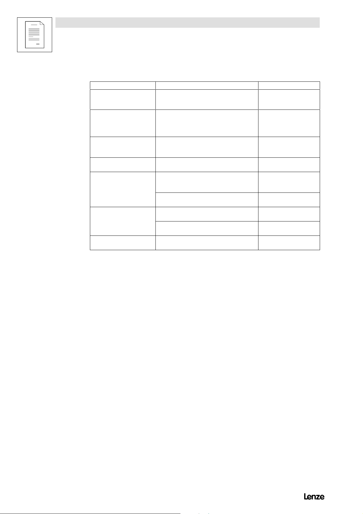
Contents of the Manual
Show/Hide Bookmarks
Part Contents Material
A T able of contents
Preface and general information
Safetyinform atio n
B T echnical data
In stallation
C Commissioning
Durin goper ation
D Configuration 406184 01/99
D1 Code table for series “Standard” 406185 01/99
D2 Code table for series “HV AC” 406186 01/99
E Troubleshooting and
fault elimin atio n
Maintenance
F Net work of sever aldriv es 406188 01/99
G Ap p licatio nofbrake un its 393658 12/96 Operat i ngIn structionsforbrakeunit8250
H Au to mation 404788 11/98 Operating Instructions for fieldbus mo dule 2102
I Accesso riesandm otors 406189 01/99 Overvi ew
K Selectionhelp
Applicatio nexam ples
L Signal-flowcharts 406191 01/99
M Glossary
Table of keywords
N
O
P
number
406181 01/99
406182 01/99
406183 01/99
406187 01/99
399907 02/98 Operating Instructions for regenerative power supply
394036 01/97 Op eratingInstru c t i onsforbrakeun i t9350
393434 12/96 Operating Instructions for fieldbus mo dule 2111
394179 01/97 Operating Instructions for fieldbus mo dule 2131
402381 06/98 Operating Instructions for fieldbus mo dule 2171/2172
391883 08/96 Operating Instructions PTC input module 8274
391882 08/96 Op eratingInstru c t i onsI/O mo dule8275
402956 11/96 Flyer: PC software Global Drive Control
403236 12/96 Catalog:Frequ encyinverter8200
401950 11/96 Flyer: Three-phase AC motors
406190 01/99
406192 01/99
Edition of Note
un i t9340
Page 4
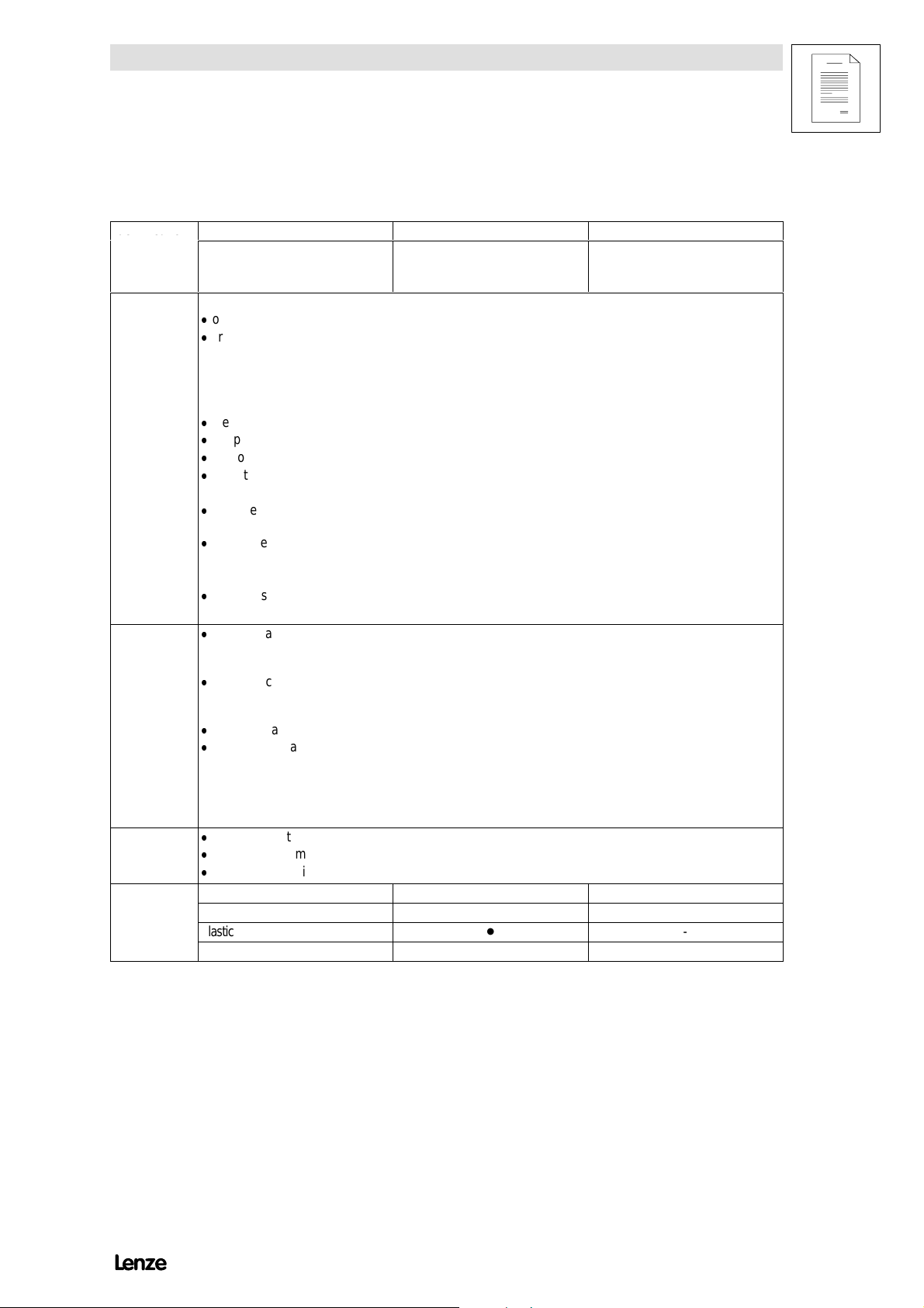
820X/821X
Show/Hide Bookmarks
Lenze
Postfach 101352 ,31763 HAM E LN
822X/824X
+U G -U G
L1 L2 L3
PAR2 0VLVIM AXDBTEMP
PAR1
SET
SH
PRG
LO A D
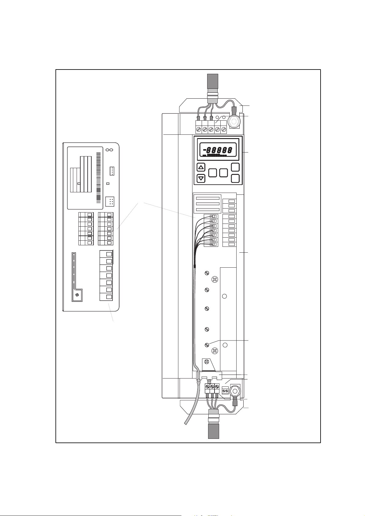
Screen-sheet m ains connection
M ains connection and
D C connection
PE
A
%
D etachable operating m odule,
Hz
as alternative
STP
RUN
Fieldbus
INTERBUS
Typ
Id .-N R
F e rt.- N r
Serien-Nr.
Eingang1
Eingang2
C ontrol Term inals
62
7
8
9
K12
K21
K22
K24
20
E1 28
E2
E3
K11
E4
39
K14
C ontrol term inals
M ains-/M otor connection
Screen connection
Screen-sheet control connections
PE
Therm al-contact connection
W
U
V
UVW
T1 T2
M otor connection
Screen-sheet m otor cables
Page 5

Contents
Show/Hide Bookmarks
Part A
1 Preface and general information 1-1...............................
1.1 Howto use this Manual 1-1...........................................
1.1.1 Terminology used 1-1.......................................
1.2 Scope of delivery 1-1................................................
1.3 Legalregulations 1-3................................................
1.4 ECDi rectives/D eclarationofConformity 1-4................................
1.4.1 What is the purpose of EC directives? 1-4.........................
1.4.2 What does the CE mark imply? 1-4.............................
1.4.3 EC Low-V oltage Directive 1-5.................................
1.4.4 EC Directive Electromagnetic Compatibility 1-7.....................
1.4.5 ECMachi neryDirect i ve 1-11...................................
2 Safety i nformation 2-1..........................................
2.1 Generalsaf etyin formation 2-1.........................................
2.2 Layout of the safety information 2-2.....................................
2.3 Residualhazards 2-2................................................
8200SHB0199
i
Page 6

Contents
Show/Hide Bookmarks
Part B
3 Technical data 3-1.............................................
3.1 Overview of types 3-1...............................................
3.2 Featu res 3-2......................................................
3.3 General data/application conditions 3-4...................................
3.4 Rated data (Operation with 150 % overload) 3-5.............................
3.4.1 Types8201 to8204 3-5.....................................
3.4.2 Types8211 to8214 3-6.....................................
3.4.3 Types8215 to8218 3-8.....................................
3.4.4 Types8221 to8224 3-10.....................................
3.4.5 Types8225 to8227 3-12.....................................
3.4.6 Types8241 to8243 3-14.....................................
3.4.7 Types8244 to8246 3-16.....................................
3.5 Rated data (Operation with 120 % overload) 3-18.............................
3.5.1 Operating conditions 3-18.....................................
3.5.2 Types821X 3-18...........................................
3.5.3 Types822X 3-19...........................................
3.5.4 Types824X 3-20...........................................
3.6 Fusesandcabl ecross-sections 3-21.....................................
3.6.1 Operation of controllers in UL-approved systems 3-21.................
3.6.1.1 Protectionof th emotorcabl es 3-21...................
3.6.2 Si ngl ed r i ves w i t h150 %ov er l oad 3-22...........................
3.6.3 Si ngl ed r i ves w i t h120 %ov er l oad 3-23...........................
3.7 Analog plug-in module 8279I B 3-24......................................
3.7.1 Features 3-24.............................................
3.8 Dim ensions 3-25....................................................
3.8.1 Analog plug-in module 3-25...................................
8200SHB0199ii
Page 7

Contents
Show/Hide Bookmarks
4 Installation 4-1................................................
4.1 Mechanical installation 4-1............................................
4.1.1 Important notes 4-1........................................
4.1.2 Standard assembly with fixing rails or fixing brackets 4-3..............
4.1.2.1 Types 8201 to8204 4-3..........................
4.1.2.2 Type 8202-V002(reduc edassem blydept h) 4-3..........
4.1.2.3 Types 8211 to8214 4-4..........................
4.1.2.4 Types 8215 to8218 4-5..........................
4.1.2.5 Types 8221 to8227 4-6..........................
4.1.2.6 Types 8241 to8246 4-7..........................
4.1.3 DIN-railass embl y 4-8.......................................
4.1.3.1 Types 8201 to8204 4-8..........................
4.1.3.2 Types 8211 to8214 4-9..........................
4.1.4 Assemblywith thermally separated power stage
(”push-through technique”) 4-10................................
4.1.4.1 Types 8215 to8218 4-11..........................
4.1.4.2 Types 8221 to8227 4-12..........................
4.1.4.3 Types 8241 to8246 4-13..........................
4.1.5 Assemblyofthe vari an t82XX-V003”coldplate” 4-14.................
4.1.5.1 General 4-14...................................
4.1.5.2 Demandsonthe cooler 4-15........................
4.1.5.3 Thermal performance of the system 4-16...............
4.1.5.4 Assemb l ypr ep ar ations 4-17........................
4.1.5.5 Assemb l yof821X-C-V003 4-18.....................
4.1.5.6 Assemb l yof822X-C-V003 4-21.....................
4.1.5.7 Assemb l yof824X-C-V003 4-22.....................
4.1.6 Assemblywi thm ainsfilter 4-23.................................
4.1.7 Assembly of the analog plug-in module 8279IB 4-24..................
4.2 Electrical in stallation 4-25.............................................
4.2.1 Oper ator’ ssafety 4-25.......................................
4.2.2 Pr otecti ono fthe controll ers 4-26...............................
4.2.3 Motor protection 4-26.......................................
4.2.4 Mains types/mains conditions 4-27..............................
4.2.5 Combination with compensation equipment 4-27.....................
4.2.6 Specification of the cables used 4-27.............................
4.2.7 Power connections 4-28......................................
4.2.7.1 Mains connection 4-28............................
4.2.7.2 Motor connection 4-29............................
4.2.7.3 Connection of a brake unit 4-34......................
4.2.7.4 Connection plan 820X 4-35.........................
4.2.7.5 Connection plan 821X 4-36.........................
4.2.7.6 Connection plan 822X/824X 4-37....................
4.2.8 Control connections 4-38.....................................
4.2.8.1 C ontrolcables 4-38..............................
4.2.8.2 Assignment of the control terminals 4-38...............
4.2.8.3 Connection diagrams 4-41.........................
4.2.8.4 Connection diagrams: Analog plug-in module 4-42........
4.3 Installation of a CE-typical drive system 4-43................................
8200SHB0199
iii
Page 8

Contents
Show/Hide Bookmarks
Part C
5 Commissioning 5-1............................................
5.1 Before switching on 5-1..............................................
5.2 Short commissioning (factory setting) 5-2..................................
5.2.1 Switch-on sequence 5-2.....................................
5.2.2 Factory setting of the most important drive parameters 5-2............
5.3 Adapt machine data 5-3..............................................
5.3.1 Determine speed range (fdmin, fdmax) 5-3........................
5.3.2 Settingofacceleration andd eceler ationtimes( Tir, Tif) 5-4.............
5.3.3 Setting of current limit values (I maxlimits) 5-5......................
5.4 Optimisation of the operating behaviour 5-6................................
5.4.1 Select control mode 5-6.....................................
5.4.2 Optimising operating modes 5-8...............................
5.4.2.1 Optimising motor-current control (C014 = -4-) 5-8.......
5.4.2.2 Optimise V/f-characteristic control with auto boost
(C014 = -0-/-1-) 5-10............................
5.4.2.3 Optimise V/f-characteristic control with constant Vmin boost
(C014 = -2-/-3-) 5-12............................
5.4.2.4 Norm alisationofan application datum 5-15.............
5.4.3 Operation with PIDcontroller 5-16...............................
5.5 Ap plication examples for PI Dcontrollers 5-18................................
5.5.1 Pumpapplication with pressure control 5-18........................
5.5.2 Pum papplication with level control 5-21...........................
5.5.3 Dancer-position control ( line drive) 5-23...........................
5.5.4 Air conditioning system 5-26...................................
6 During operation 6-1...........................................
6.1 Operating information 6-1............................................
6.1.1 General 6-1..............................................
6.1.2 822X /824X 6-2...........................................
6.1.3 8218-V003 6-2...........................................
6.2 Display of the controller status 6-2......................................
8200SHB0199iv
Page 9

Contents
Show/Hide Bookmarks
Part D
7 Configuration 7-1..............................................
7.1 8201BB operatingmodule 7-2.........................................
7.2 Structure of the operating program 7-4...................................
7.2.1 Oper ati nglevel 7-4........................................
7.2.2 Code level 7-4............................................
7.2.3 Parameterlevel 7-5........................................
7.3 Change and store parameters 7-5.......................................
7.3.1 Chan ge andstor eparameter swi t hthe8201BB operatingmodule 7-6.....
7.3.2 Change and store parameters with fieldbus modules. 7-8..............
7.3.3 Dynamic parameter change 7-8...............................
7.4 Operating functions 7-9..............................................
7.4.1 Operating mode 7-9........................................
7.4.2 Working with parameter sets 7-10...............................
7.4.3 Change parameter set via DC-bus voltage 7-12.....................
7.4.3.1 AC-motorbrakingbymeansofparameter setch angeover 7-12
7.4.3.2 Automatic parameter set changeover for controlled
deceleration in the event of mains failure 7-13...........
7.5 Control functions 7-15................................................
7.5.1 Speed range (fdmin, fdmax) 7-15...............................
7.5.2 Accelerationanddecelerat iontimesTi r, Tif 7-16.....................
7.5.3 Current limit values (I m ax limitvalues) 7-17........................
7.5.4 Current limitation controller (I m ax controller) 7-18....................
7.5.5 Control m ode 7-19.........................................
7.5.6 V /fch ar act eristi c 7-22.......................................
7.5.6.1 V /f-ratedfreq uencyfdr 7-22........................
7.5.6.2 V minsetti ng 7-24................................
7.5.7 Configuration 7-26..........................................
7.5.8 Motor data detection 7-27....................................
7.5.9 Running optimisation 7-28....................................
7.5.9.1 Sl i pcompensati on 7-28...........................
7.5.9.2 Chopper frequency 7-29...........................
7.5.9.3 Oscillation damping 7-31..........................
7.5.9.4 Ramp function generator S-shape 7-32................
7.5.9.5 Ski pfreq uenci es 7-33.............................
7.5.10 PIDcont rol l eras processcont rol l er 7-34..........................
7.5.10.1 R eset integral component and influence 7-38............
7.5.10.2 Setpoint selection for the process controller 7-38..........
7.5.10.3 Frequency precontrol 7-39.........................
7.5.10.4 Fr equen cysett i ngrange 7-39.......................
7.5.11 Setpoint input 7-40.........................................
7.5.11.1 Analog setpoint input 7-40.........................
7.5.11.2 Setpoint input using the keypad 7-42..................
7.5.11.3 Setpoint input via JOG frequencies 7-43................
7.5.11.4 Setpoint input via function ”Motor potentiometer” 7-44......
7.5.11.5 Setpoint input via of the function ”Motor potentiometer in
combin ation withJOG value” 7-46....................
7.5.11.6 Setpoint su m 7-47...............................
8200SHB0199
v
Page 10

Contents
Show/Hide Bookmarks
7.5.12 Con t r ollerenabl e RFR 7-48....................................
7.5.13 Start conditions/flying-restart circuit 7-49..........................
7.5.14 Function of the inputs to be configured block by block 7-50.............
7.5.14.1 Level inversion for digital inputs 7-52..................
7.5.14.2 Priority mask for digital inputs 7-53...................
7.5.14.3 Change of the direction of rotation (CW/CCW) 7-54........
7.5.14.4 Q uickstopQS P 7-55.............................
7.5.14.5 DC-in jectio nbr ake(DCB) 7-56.......................
7.5.14.6 Parametersetchan geov erPAR 7-58..................
7.5.14.7 TRIPset 7-58..................................
7.5.14.8 Manual/rem ote chan geover 7-59.....................
7.5.14.9 Digital frequency input 7-60.........................
7.5.15 In direct torque limitation 7-61..................................
7.6 Display functions 7-62................................................
7.6.1 Displ ayvalues 7-62.........................................
7.6.2 Switch-on display 7-62.......................................
7.6.3 Normalisation of an application datum 7-63........................
7.6.4 Elapsed operating time meter 7-64..............................
7.6.5 Software versionandcontrollertype 7-64..........................
7.7 Monitoring functions 7-65.............................................
7.7.1 Relay outputs 7-65.........................................
7.7.2 Analog output 7-69.........................................
7.7.3 Thermal motor monitoring 7-71.................................
7.7.3.1 I 2x t monitorin g 7-71.............................
7.7.3.2 PTC input 7-72.................................
7.7.4 Motor-phase failure detection 7-73..............................
Part D1
7.8 Code table for “Standard” series 7-77.....................................
Part D2
7.9 Code table for “HV AC” series 7-85.......................................
8200SHB0199vi
Page 11

Contents
Show/Hide Bookmarks
Part E
8 Troubleshooting and fault elimination 8-1...........................
8.1 T roubleshooting 8-1.................................................
8.1.1 Display at the controller 8-1..................................
8.1.2 Display at the operating module 8-1.............................
8.1.3 Maloperation of the drive 8-2.................................
8.2 Fault analysis wi ththe historybuffer 8-2..................................
8.3 Fault messages 8-2.................................................
8.4 Reset of fault messages 8-4...........................................
9 Maintenance 9-1..............................................
9.1 Maintenance services 9-1............................................
9.2 Service addresses 9-2...............................................
Part F
10 Network of several drives 10-1....................................
10.1 Funct i on 10-1......................................................
10.2 Conditions for trouble-free network operation 10-2............................
10.2.1 Possible combinations 10-2...................................
10.2.2 Mains connection 10-3.......................................
10.2.2.1 C ab le protection/cab l ecross-section 10-3..............
10.2.2.2 Main scho k e/m ainsfilter 10-3.......................
10.2.2.3 C ont r ollerprotection 10-3..........................
10.2.3 DC-bus connection 10-4......................................
10.2.4 Fusesandcablecro ss-sections fo ra networ kofseveraldr iv es 10-6.......
10.2.5 Prot ection innetworksofs everaldri ves 10-7.......................
10.3 Selecti onbasics 10-9................................................
10.3.1 Conditions 10-9............................................
10.3.2 Selecti onexample fo r4 drives 10-12..............................
10.3.2.1 Supplyonly via controllers 10-12......................
10.3.2.2 Supplyby means of 934Xsupply and feedback module 10-13.
10.4 Central supply 10-14..................................................
10.4.1 Central supply of 820X 10-14...................................
10.4.2 Central supply via 934Xfor821X/822X /824X/93XX 10-15...............
10.5 Decentral supply 10-16................................................
10.5.1 Decentral supply for 820X 10-16.................................
10.5.2 Central supply for 821X/822X /824X/93X X/934X 10-17.................
See also table of contents of the attached Operating Instructions
8200SHB0199
vii
Page 12

Contents
Show/Hide Bookmarks
Part G
11 Application of brake units
See: Table of contents of the attached Operating Instructions
Part H
12 Automation
See: Table of contents of the attached Operating Instructions
Part I
13 Accessories (Survey) 13-1........................................
13.1 Access oriesforall ty pes 13-1...........................................
13.2 Softw ar e 13-1.....................................................
13.3 Type-specificaccessories 13-2..........................................
13.3.1 T ypes820X 13-2...........................................
13.3.2 T ypes821X 13-3...........................................
13.3.3 T ypes822X 13-4...........................................
13.3.4 T ypes824X 13-5...........................................
Part K
14 Selection help 14-1.............................................
15 Application examples 15-1.......................................
15.1 Pum papplicationwithpressure control 15-1................................
15.2 Pum papplication with level control 15-4...................................
15.3 Dancer-positioncontrol(line drive) 15-6....................................
15.4 Air conditioning system 15-8...........................................
8200SHB0199viii
Page 13

Contents
Show/Hide Bookmarks
Part L
16 Signal-flow charts 16-1..........................................
16.1 Sig nal-flowchartfortypes820X 16-2.....................................
16.1.1 Con t r olst r uctu r e 16-2.......................................
16.1.2 Inver t ercon trol 16-3........................................
16.1.3 Mo nitorings 16-3...........................................
16.2 Sig nal-flowchartsfortypes 821X/822X/824X 16-4............................
16.2.1 Control structure control mode V/f control 16-4......................
16.2.2 Control structure control mode motor current control 16-5..............
16.2.3 Inver t ercon trol 16-6........................................
16.2.4 Mo nitorings 16-6...........................................
16.3 Sig nal-flowchartsfortypes 821X/822X/824X-H VAC 16-7.......................
16.3.1 Processandspeedco ntroll erforC005 = -0- 16-7...................
16.3.2 Processandspeedco ntroll erforC005 = -1- ... -7- 16-8...............
Part M
17 Gl ossary 17-1..................................................
18 Table of keywords 18-1..........................................
8200SHB0199
ix
Page 14

Contents
Show/Hide Bookmarks
8200SHB0199x
Page 15

EDS8200U--A
Show/Hide Bookmarks
00406181
Manual
Part A
Table of contents
Preface and general information
Safety information
= G l obal Drive
Frequ ency inv erters 8200
Page 16

This Manual is valid for 82XX controllers as of version:
Show/Hide Bookmarks
33.820X- E - 1x. 1x (8201- 8204)
33.8202- E- 1x. 1x -V002 Redu c edassem blydep t h(8202)
33.821X- E - 0x. 1x (8211- 8218)
33.821X- E - 1x. 2x (8211- 8218)
33.821X- C- 1x. 2x -V003 Coldplate(8215- 8218)
33.821X- E - 3a. 3x -V020 HVAC (8211 - 8218)
33.822X- E - 0x. 0x (8221- 8227)
33.822X- C- 1x. 2x -V003 Coldplate(8221- 8222)
33.822X- E - 3a. 3x -V020 HVAC (8221 - 8227)
33.824X- E - 1x. 1x (8241- 8246)
33.824X- C- 1x. 1x -V003 Coldplate(8241- 8246)
33.824X- E - 3a. 3x -V020 HVAC (8241 - 8246)
Type
Design:
B = Module
C= Coldplate
E = Built-in unitIP 20
Hardware version and index
Softwareversionandindex
Variant
Explanation
Edition of: 01/1999
revised
Page 17
Preface and general information
Show/Hide Bookmarks
1 Preface and general information
1.1 How to use this Manual
- This Manual completes the Operating Instructions for 82XXfrequency
inverters.
- It contains the Operating Instructions and additional information on planning,
adaptability and the accessories valid at the time of printing.
- In case of doubt, refer to the Operating Instructions delivered with the
82XXfrequency inverters.
- The Manual is a help to select and adapt the 82XXfrequency inverters and
the accessories to ensure safe and trouble-free operation. It contains safety
information which must be observed.
- The Manual must always be in a complete and perfectly readable state.
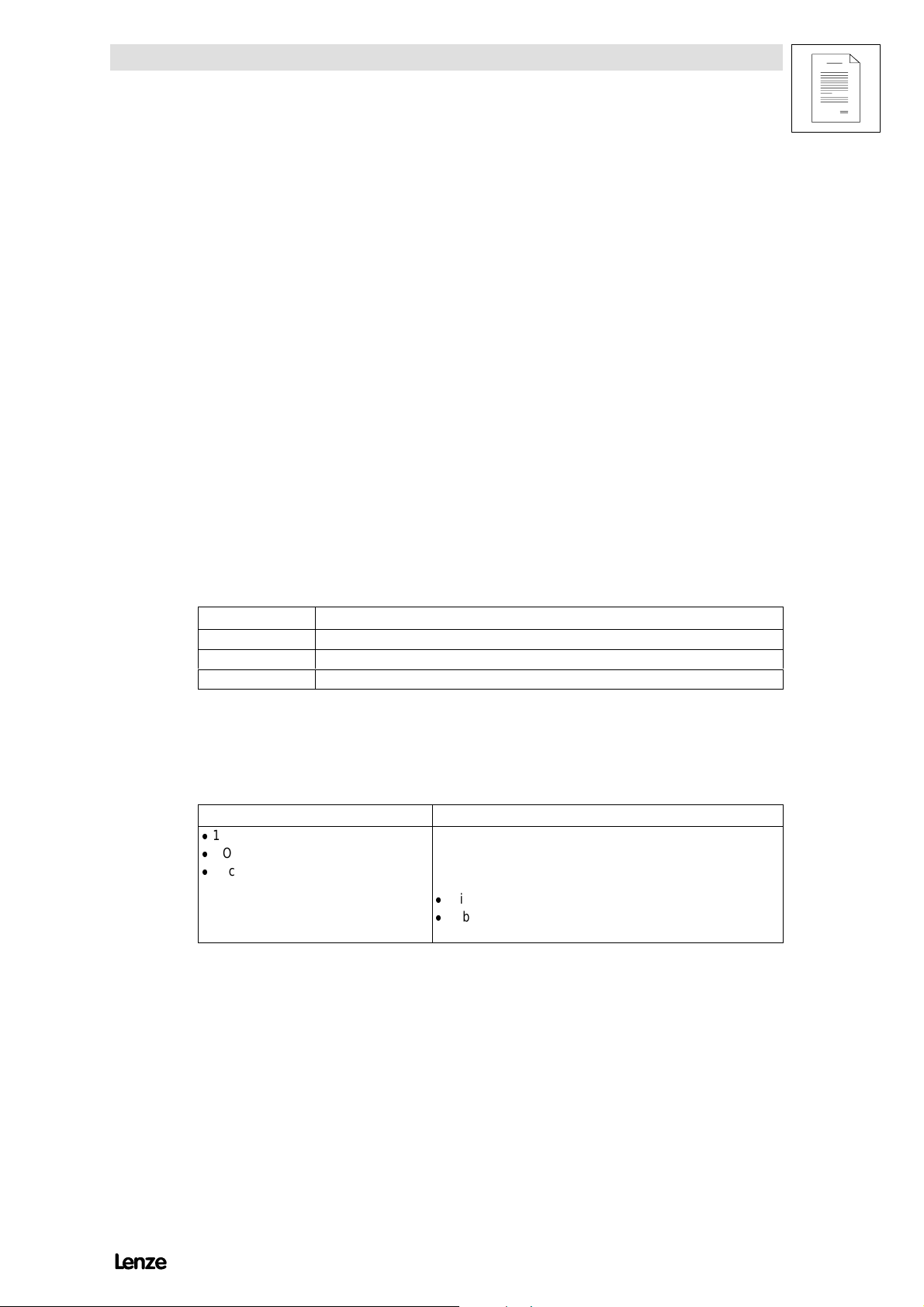
1.1.1 Terminology used
Term In the following text used for
82XX Anyfrequencyinvert erof the series8200, 8210, 8220, 8240
Controllers 82XX frequency inverter
Drive system Driv esystem swith82XXfrequencyinvertersand other Lenze drivecomp o nen ts
1.2 Scope of delivery
Scope of delivery Important
-
1 82XXfrequency inverter
-
1 Operating Instructions
-
1 accesso rykit (comp o n en tsandpieces
fo rmechanicalandelectricalinstallation)
Afterrecepti onofthedelivery, checkim mediatelywhetherthe scope
of supply matches the accompanying papers. Lenze does not accept
anyliability for deficiencies claimedsubs equ ently.
Claim
-
visible transport damage immediately to the forwarder.
-
visib ledeficiencies/incom pletenessimmediatelytoyou rLenze
rep resent ative.
8200SHB0199
1-1
Page 18
Preface and general information
Show/Hide Bookmarks
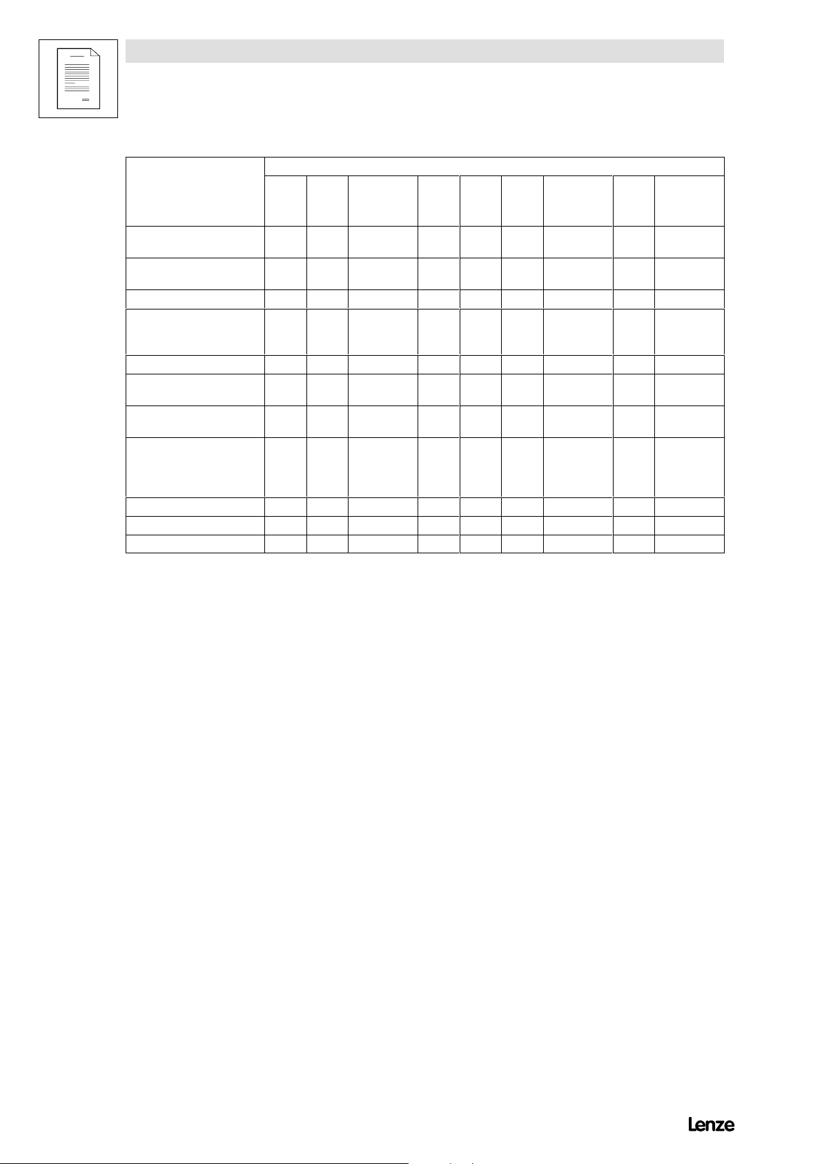
Accessorykit
820X 821X 821X-V003 8221
8222
8223
7-pole socket connectors for
contr o lcables
3-pole socket connectors for
relay output K2
Fixingrails 2 2 2 - - - - 2 Fixing units incl. screws for
fixingthe inverter tothe
housing
PGdiaphragm gland 21 - - - 1 1 1 1 - Screensheetfo rcont rol
cables incl. fixingscrew
Screensheetfo rmo t orcable
incl. two fixing screws
Hexagon nuts incl. washers
and spring-lock washers for
the electrical connectio nof
thepowerstage
Heat-conducting paste - - 1 tube - - - 1 tube - 1 tube
Gasket - - 1 - - - 1 - 1
Tightening frame - - 1 - - - 2 - 2
2 2 2 2 2 2 2 2 2
- - - 1 1 1 1 1 1
- - - 4 4 - - - -
- - - 1 1 1 1 1 1
- - - 1 1 1 1 1 1
- - - 8M6 8M8 8M10 8M6 - -
8224
8225
8226
8227
8221-V003
8222-V003
824X 824X-V003
8200SHB01991-2
Page 19
1.3 Legal regulations
Identificatio
n
Disposa
l
Show/Hide Bookmarks
Preface and general information
Identification
Application
as directed
Liability
Warranty
Disposal
Nameplate CE-identification Manufacturer
Lenze controllers are unambiguously
designated bythe contents of the
nameplate.
Conforms to the EC Low Voltage
Directive
Lenze GmbH &Co KG
Postfac h101352
D-31763Hameln
82XX frequency inverter
-
operate the controller only under the conditions prescribed in these operating instructions.
-
are components
- foropenandclo sedloopedco ntrol ofvariable speeddriveswithasynchro nous standardm otors,relu c t ance
motors, PMsynchronous motors with asynchronous damper cage,
- for installation into a machine,
- used for assembly together with other components to forma machine.
-
are electric units for the installation into control cabinets or similar enclosed operating housing.
-
comply with the requirements of the Low-Voltage Directive.
-
are not machines for the purpose of the Machinery Directive.
-
are not to be used as domestic appliances, but only for industrial purposes.
Drivesystems with 82XX frequency inverters
-
meetthe ECElectrom agn etic Comp atibilityDirective ifthey are installed accordin gto the guidelinesof CE-typical
drive systems.
-
can be used
- on public and no n-pu b licmains,
- in industrial as well as residential and commercial premises.
-
The user is responsible for the compliance of his application with the EC directives.
Any other use shall be deemed inappropriate!
-
The information, data, and notes in these instructions met the state of the art at the time of printing. Claims on
m odif icatio nsreferringto cont roll erswh i chhavealread ybeensuppli edcannot be derivedfromtheinformation,
illustratio n s,and description s.
-
The specifications, processes, and circuitry described in these instructions are for guidance only and mustbe
adapted to yo u row nspecific application. Lenze doesnottake respo n sib ilityfor thesuitabilityof the pro cessand
circuit proposals.
-
The specifications in these instructions describe the product features without guaranteeing them.
-
Lenzedoesnotaccept anyliabilityfordamageand operatinginterference causedby:
- disregarding the operating instructions
- unauthorised modifications to the controller
- operating errors
- improper working onand with the controller
-
Warrantyco ndit i ons :SeeSalesandDeliveryCond i tionsofLenze G mbH&Co KG .
-
Warrantyclaims mustbe made toLenze immediatel yafterdetecti ngthedefici encyorfault.
-
Thewarrantyisvoidin all cases w hereliability claims cannot be mad e.
Material Recycle Dispose
Metal - Plastic - Assembled PCBs - -
8200SHB0199
1-3
Page 20

Preface and general information
Show/Hide Bookmarks
1.4 EC Directives/Declaration of Conformity
1.4.1 What is the purpose of EC directives?
EC directives are issued by the European Council and are intended for the
determinationofcommon technicalrequirements (harmonisation)and certification
procedures within the European Community. A t the moment, there are 21 EC
directivesofproduct ranges.Thedirectivesareor willbeconverted to nationallaws
of the member states. A certification issued by one member state is valid
automatically without any further approval in all other member states.
The texts of the directive are restricted to the essential requirements. Technical
details are or will be determined by European harmonised standards.
1.4.2 What does the CE mark imply?
After a verification, the conformity according to the EC directives is certified by
affixing a CE mark. Within the EC there are no commercial barriers for a product
withthe CEmark.
The enclosure of a conformity certification is not necessary according to most
directives. Therefore, the customer is not able to appreciate which of the 21 EC
directivesapplies to a product andwhichharmonised standardsareconsidered
in the conformity verification.
Controllers on their own with the CE mark exclusively correspond to the Low
Voltage Directive. For the compliance with the EMC Directive only general
recommendations have been issued so far. The CE conformity of the installed
machine remains the responsibility of the user. For the installation of CE-typical
drivesystems,LenzehasalreadyprovedtheCEconformitytotheEMCDirective.
8200SHB01991-4
Page 21

Preface and general information
Show/Hide Bookmarks
1.4.3 EC Low-Voltage Directive
(73/23/EEC)
amended by: CE Mark Directive (93/68/EEC)
General
- The Low-Voltage Directive is effective for all electrical equipment for use
with a rated voltage between 50 V and 1000 V AC and between 75 V and
1500 V DC, and under normal ambient conditions. The use of e.g. electrica l
equipment in explosive atmospheres and electrical parts in passenger and
goods lifts are excepted.
- The objective of the Low Voltage Directive is to ensure that only electrical
equipment which does not endanger the safety of persons or animals is
placed on the market. It should also be designed to conserve material
assets.
8200SHB0199
1-5
Page 22
Preface and general information
Show/Hide Bookmarks
EC Declaration of Conformity ’95
for the purpose of the EC Low-Voltage Directive (73/23/EEC)
amended by: CE Mark Directive (93/68/EEC)
820X/821X/822X/824X controllers are developed, designed, and manufactured
incompliance with the abovementioned ECDirective under thesole responsibility
of
Lenze GmbH & Co KG, Postfach 10 13 52, D-31763 Hameln
Standards considered:
Standard
DINV DE0160 5.88 +A1/ 4.89 +A2 /10.88
DINEN50178
Classificati onVDE0160 / 11.94
DINV DE0100 S tand ardsfor theinstallation of powerinstallations
EN60529 IP degrees of protection
IEC 249 / 1 10/86, IEC249 / 2-15 / 12/89 Base material for printed circuits
IEC 326 / 1 10/90, EN60097 / 9.93 Prin tedcircuits, printed boards
DINV DE0110 /1-2 /1/89 /20/ 8/90 Creepacedistancesandclearan c es
Electronic equipment for use in electrical power
installations
Hameln, 01 October, 1995
________________
(i.V.Loy)
Product Manager
8200SHB01991-6
Page 23

Preface and general information
Show/Hide Bookmarks
1.4.4 EC Directive Electromagnetic Compatibility
(89/336/EEC)
amended by: F irst Amendment Directive (92/31/EEC)
CEMark Directive(93/68/EEC)
General
- The EC Electromagnetic Compatibility Directive is effective for ”devices”
which may cause electromagnetic interference or the operation of which
may be impaired by such interference.
- The aim is to limit the generation of electromagnetic interference so that an
operation without interference to radio and telecommunication systems and
other equipment is possible. The devices must also show an appropriate
resistance against electromagnetic interference to ensure the application as
directed.
- Controllers cannot be driven in stand-alone operation and therefore the
controllers cannot be evaluated on their own in terms of EMC. Only after the
integration of the controllers into a drive system, can this system be tested
concerning the objectives of the EC EMC Directive and the compliance with
the ”Law about the Electromagnetic Compatibility of Devices”.
- Lenze has verified the conformity of controllers integrated into certain
defined drive systems. In the following these systems are called ”CE-typical
drivesystems”.
The following configurations can now be selected by the user:
- The user himself can determine the system components and their
integration into the drive system and is then held responsible for the
conformityof the drive.
- The user can select the CE-typcial drive systems for which the
manufacturer has already proved the conformity.
8200SHB0199
1-7
Page 24
Preface and general information
Show/Hide Bookmarks
Components of the CE-typical drive system
System component Specification
Contr o ller 820X/821X/822X/824Xcontro l l er s
For type designation see inner cover page
RFIfilter For data and data assignment, see chapter ”Accessories ”
Mains choke For data and data assignment, see chapter ”Accessories”
Mainsfilters For data and data assignment, see chapter ”Accessories”
Motor cable Screenedpowercable withtinned E-CUbraidwitha m inimumof 85 % optical
Mainscable betw eenRFIfilter
and controller
Contr o lcables Screen edsignal cable typeLIYCY
Motor Standard three-phase AC asynchronous motor
Accesso r ies Forratedaccessories ,seeinnercoverpage.
- Controller, RFI filter and mains choke are mounted on one assembly board.
cov erag e
As fromcable length 300 mm:
Screenedpow ercable withtinnedE-CUbraid witha minimumof 85 % optical
cov erag e
Lenzetype DXRA or similar
- The system components are functionally wired according to chapter 4,
”Electrical installation”.
Application as directed/Scope of application
- The820X/821X/822X/824X controllers areintended for the useincontrol
cabinets.
- The820X/821X/822X/824X controllers aredirected as components for the
control of variable-speed drives with three-phase AC motors to be
assembled together with other components to form a drivesystem.
The drive systems are intended for installation into a machine or for the
constructiontogetherwith other components to form a machine or a plant.
- Drive syste mswith the 820X/821X/822X/824X controllers, which are
installed according to the guidelines of CE-typical drive systems,
correspond to the EC EMC Directive and the standards mentioned below.
- The CE-typical drive systems are suitable for the operation on public and
non-public mains.
- The CE-typical drive systems are provided for the operation in industrial
premises as well as in residential and commercial areas.
- Because of the earth-potential reference of the RF I filters, the described
CE-typical drive systems are not suitable for the connection to IT-mains
(mains without earth-reference potential).
8200SHB01991-8
- The controllers are not domestic appliances, but they are intended as a part
of drivesystems for commercialuse.
Page 25
Preface and general information
Show/Hide Bookmarks
EC Declaration of Conformity ’95 for the purpose of the EC
Directive
on Electromagnetic Compatibility (89/336/EEC)
amended by: F irst Amendment Directive (92/31/EEC)
CEMark Directive(93/68/EEC)
820X/821X/822X/824Xcontrollerscannot be driven in stand-alone operation for
the purpose of the R egulation about Electromagnetic Compatibility (EMVG of
9/11/92 and 1. EMVGÄndG of 08 August, 1995). The EMC can only be verified
when thecontroller isintegrated into a drive system.
Lenze GmbH & Co KG, Postfach 10 13 52, D-31763 Hameln
declaresthat thedescribed ”CE-typicaldrivesystems” withthe controllersof the
types 820X/821X/822X/824X comply with the above mentioned EC Directive.
Theconformity evalua tion is based on the working paper of the product standard
for drive systems:
IEC 22G-W G4 5/94 EMC product standard including specific test methods for power drive systems”
Generic standardsconsidered:
Generic standard
EN50081-1 /92 Generic standard for the emission of noise
Part 1: Residential area, commercial premises, and small businesses
EN50081-2 /93
(u sedinadditionto the
requirements of IEC 22G)
prEN50082-2 3/94 Generic standard for noise immunity
Generic standard for the emission of noise
Part 2: Industrial premises
The emission of noise in industrial premises is not limited in IEC 22G.
Part 2: Industrial premises
The requirements of noise immunity for residential areas were not considered
since they are less strict.
8200SHB0199
1-9
Page 26
Preface and general information
Show/Hide Bookmarks
Considered basic standards for the test of noise emission:
Basic standard Test Limit value
EN55022 7/92 R adio interference housing and mains
EN55011 7/92
(u sedinadditionto the
requirements of IEC 22G)
IEC 801-2 /91 Electrostatic discharge
IEC 1000-4-3 Electromagnetic fields
ENV50140 /93 High-frequency field
IEC 801-4 /88 Fast transients
IEC 801-5 Surge test
Freq uencyrange0.15 - 1000MHz
Radio interference housing and mains
Freq uencyrange0.15 - 1000MHz
The emission of noise in industrial premises is not
limitedin IEC22G.
on housing and heat sink
Freq uencyrange26 - 1000 MHz
Freq uencyrange80 - 1000 MHz,
80 % amplitude modulated
Fixed frequency
900 MH zwith200 Hz, 100 %modulated
burst on power terminals
Burst on bus and control cables Severity 4
Mainscables
Class B
for use in residential areas
and commercial premises
Class A
foruse in
industrial premesis
Severity 3
6 kV with contact discharge
8 kV air discharge
Severity 3
10 V/m
Severity 3
10 V/m
10 V/m
Severity 3
2kV/5kHz
2kV/5kHz
In stallatio nclass 3
Hameln, 01 October, 1995
________________
(i.V.Loy)
Product Manager
8200SHB01991-10
Page 27

Preface and general information
Show/Hide Bookmarks
1.4.5 EC MachineryDirective
(89/392/EEC)
amended by: First Amendment Directive(91/368/EEC)
Second Amendment Directive (93/44/EE C)
CEMark Directive(93/68/EEC)
General
For the purpose of the Machinery Directive, ”machinery” means an assembly of
linked parts or components, at least one of which moves, with the appropriate
actuators, control and power circuits, etc., joined together for a specific
application, in particular for the processing, treatment, moving or packaging of a
material.
8200SHB0199
1-11
Page 28

Preface and general information
Show/Hide Bookmarks
EC Manufacturer’s Declaration
for the purpose of the EC Machinery Directive (98/392/EEC)
amended by: First Amendment Directive (91/368/EE C)
Second Amendment Directive (93/44/EE C)
CE Mark Directive (93/68/EEC)
The 820X/821X /822X/824X controllers were developed, designed, and
manufactured under the sole responsibility of
Lenze GmbH & Co KG, Postfach 10 13 52, D-31763 Hameln
Commissioning of the controllers is prohibited until it is proven that the machine
in which they are to be installed corresponds to the EC Machinery Directive.
Hameln, 01 October, 1995
________________
(i.V.Loy)
Product Manager
8200SHB01991-12
Page 29
2 Safety information
Show/Hide Bookmarks
2.1 General safety information
Safety and application notesfor controllers
(to: Low-V oltage Directive 73/23/EEC)
Safety information
1. General
Dur in goperatio n , drive controllersmay have, accordin gtotheir
ty pe o fprot ec t i on,live,bar e,inso me casesalsomovab l eor
rotatingpartsaswellashotsurfaces.
Non-authorised removal of the required cover, inappropriate use,
inc orr ectinstall ationoroperatio n, creates theris kofsevereinjury
toper sonsordamagetomaterialasset s.
Further information can be obtained from the documentation.
All operations concerning transport, installation, and
commis sioningas w el las maintenancemustbecarriedoutby
qualified, skilled perso n nel(I E C364 and CENEL ECHD384 orDI N
VDE0100 and IECrep ort664 or DI NVD E0110 andnati onal
regulations for the prevention of accidents mustbe observed).
Accord in gtothisbasic safetyinformationqualifiedskilled
perso nn elare person swh oare familiarwiththe erection,
assembly , comm issioning, and operation of the product and who
have the qualifications necessary for their occupation.
2. Application as directed
Drive controllers are components which are designed for
installati oninelectr i calsyst ems o rmachi nery.
W heninstallingin machin es,com missio n ingof thedrive
contr o llers( i.e. the starting of operationas directed)is pro h ib ited
until it is proven that the machine corresponds to the regulations
oftheECDirectiv e89/392/EEC( MachineryDirect i ve); EN60204
must be observed.
Com missio n ing(i.e. startingof operationas directed) is on ly
allowedwh enthere is com p liancewiththe EM CDirectiv e
( 89/336/EEC).
The drive controllers meet the requirements of the LowVoltage
Directiv e73/23/EEC.Theharmonis edstand ardsoftheEN50178/
DINV DE0160 seriestog et her withEN60439-1/DINVD E0660
part500 andEN60146/DINV DE0558 areappl i cable to drive
controllers.
The technical data and information on the connection conditions
m ustbeobt ai nedfromthenameplat eandthe docu mentationand
m ustbeobservedin all cas es.
3. Transport, storage
Notes on transport, storage and appropriate handling must be
observed.
Climaticcondit ionsmust be observedaccor dingto EN50178.
4. Erection
The devices must be erected and cooled according to the
regulations of the corresponding documentation.
The drive controllers must be protected from inappropriate loads.
Particularly during transport and handling, components must not
be bent and/or isolating distances mustnot be changed. Touching
ofelectron i cco mpon entsandco ntactsmust be av oided.
Driv econtro llerscon tainelectrostaticallysensitivecomp o n ents
which can easily be damaged by inappropriate handling. Electrical
compon entsmustnot be damaged ordest royedmechanic al l y
(health risks are possible!).
5. Electrical connection
W henwo r kingon live drivecontro llers ,the validnational
regulations for the prevention of accidents ( e.g. VBG4)must be
observed.
Th eelectr i c alinstall at i onm ustbecarriedoutacco rdingtothe
appropriate regulations (e.g. cable cross-sections, fuses, PE
connection). More detailed information is included in the
documentation.
No tesconcernin gthe installationin compliancewithEMC- such
as screening, grounding, arrangement of filters and laying of
cables - are included in the documentation of the drive controllers.
These notes mustalso be observed in all cases for drive
controllers with the CE mark. The compliance with the required
limitvaluesdemandedbythe EMClegislationis the respon sib ility
ofthem anufac t urerofth esy stemormachine.
6. Operation
Systems where drive controllers are installed must be equipped, if
necessary, with additional monitoring and protective devices
according to the valid safety regulations, e.g. law on technical
tools, regulations for the prevention of accidents, etc.
Mo d ification softhe driv econtrollersby theoperatingsoftw are are
allowed.
After disconnecting the drive controllers from the supply voltage,
live parts of the controller and power connections must not be
touched immediately, because of possibly charged capacitors. For
this, observe the corresponding labels on the drive controllers.
During operation, all covers and doors must be closed.
7.Maintenance and servicing
The manufacturer’s documentation must be observed.
This safety information must be kept!
The product-specific safety and application notes in these Operating Instructions must also be observed!
8200SHB0199
2-1
Page 30
Safety information
Show/Hide Bookmarks
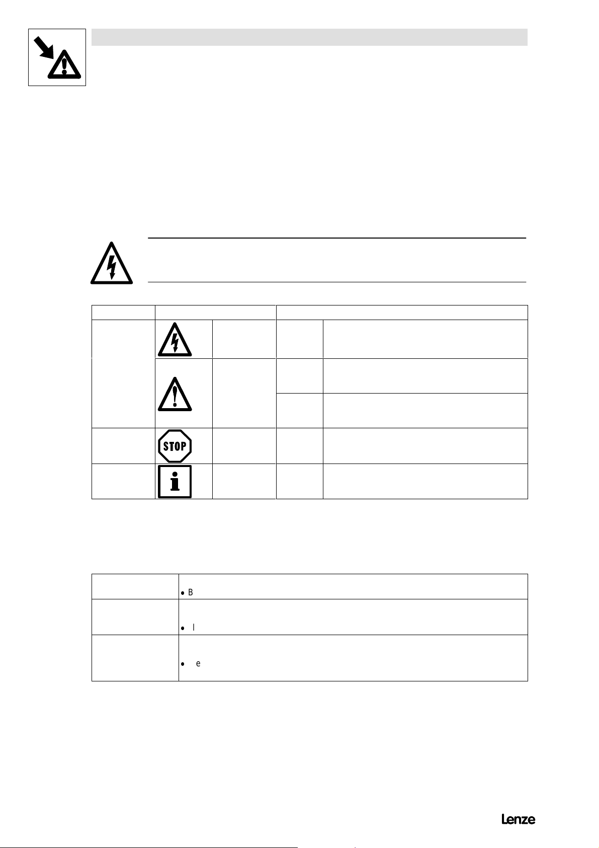
2.2 Layout of the safet y information
- All safety information has a uniform layout:
- The icon characterises the type of danger.
- The signal word characterises the severity of danger.
- The note describes the danger and suggests how to avoid the danger.
Signal word
Note
Icons used Signal words
Warning of
danger to
persons
Warning of
damage to
material
Other notes Note! Designates a general, useful note.
Warning of
hazardous
electr i c alvolt age
Warning of a
general danger
Danger! Warns of impending dangeU .
Consequences if disregarded:
Deat horsevere injur i es.
Warning! Warns of potential,very hazardous situations.
Possible consequences if disregarded:
Deat horsevere injur i es.
Caution! Warns of potential,hazardous situations .
Possible consequences if disregarded:
Light or minor injuries.
Stop! Warns of potential damage to material .
Possible consequences if disregarded:
Dam ageof the contro ller/driv e systemorits enviro n ment
Ifthisnote is obs erved , handlingof the contr o ller/driv e
systemis easier.
.
2.3 Residual hazards
Operator’s safety After mains disconnection, the power terminals U, V, Wand +UG,-UGremainliv efo rat least3 minutes .
Protection of devices Cyclic connection and disconnection of the controller supply voltage at L1, L2, L3 or +UG,+UGmay
Overspeeds Drive systems can reach dangerous overspeeds (e.g. setting high field frequencies for motorsand
8200SHB01992-2
-
Before working onthe controller, check that no voltage is applied to the power terminals.
overload the internal input current limit.
-
Allow at least 3 minutes between disconnection and reconnection.
machines which are not suitable):
-
The controllers do not offer any protection against these operating conditions. Use additional
com po n entsforthis.
Page 31

EDS8200U--B
Show/Hide Bookmarks
00406182
Manual
Part B
Technical data
Installation
= G l obal Drive
Frequ ency inv erters 8200
Page 32

This Manual is valid for 82XX controllers as of version:
Show/Hide Bookmarks
33.820X- E - 1x. 1x (8201- 8204)
33.8202- E- 1x. 1x -V002 Reducedassembl ydepth(8202)
33.821X- E - 0x. 1x (8211- 8218)
33.821X- E - 1x. 2x (8211- 8218)
33.821X- C- 1x. 2x -V003 Coldplate(8215- 8218)
33.821X- E - 3a. 3x -V020 HVAC (8211 - 8218)
33.822X- E - 0x. 0x (8221- 8227)
33.822X- C- 1x. 2x -V003 Coldplate(8221- 8222)
33.822X- E - 3a. 3x -V020 HVAC (8221 - 8227)
33.824X- E - 1x. 1x (8241- 8246)
33.824X- C- 1x. 1x -V003 Coldplate(8241- 8246)
33.824X- E - 3a. 3x -V020 HVAC (8241 - 8246)
Type
Design:
B = Module
C= Coldplate
E = Built-in unitIP 20
Hardware version and index
Softwareversionandindex
Variant
Explanation
Edition of: 01/1999
revised
Page 33

3 Technical data
Show/Hide Bookmarks
3.1 Overview of types
Technical Data
Motor power (4-pole ASM 230/400V)
kW
90
75
55
45
30
22
15
11
7.5
5.5
4.0
3.0
2.2
8204
8218
8217
8216
8215
8214
8213
Frame size
8227
8226
8225
8224
8223
8222
8221
8246
8245
8244
1.5
0.75
0.75
0.55
0.37
FIG 3-1 Overview of types
8203
8202
8202
V002
8201
L1/N/PE
AC 220/230V
8212
8211
Rated voltage
L1/L2/L3/PE
AC 400/460V
L1/L2/L3/PE
AC 400/480V
8243
8242
8241
L1/L2/L3/PE
AC 400/480V
8200SHB0199
3-1
Page 34

Technical Data
Show/Hide Bookmarks
3.2 Features
820X 821X 822X 824X
Co mpact desig n
Loadcapacit yof upto150 %Irfor1 min
Inverter outputs are protected against short circuit
Earth-fault check at mains connection
Chopper frequency 9.2 kHz
Chopper frequency selectable: 4 kHz, 8 kHz, 12 kHz, 16 kHz
V/f-characterist i cco ntrol withcons t ant V
boost or auto boost
min
Motor-current control orV/f-characteristic control selectable
Mains -vo ltagecomp ens ation
Slipcom p ens atio n
Adjus tablecurrentlimitationwith V/f-ov errid e
PWM converterwithIGBT-powerstages
DC-bus connection and brake-chopper connection
Isolated analog input and output
Relay outputs (change-over contact) 1 1 2 2
PLC-compatibledigitalout puts(I/O module8275) 3 (option) 3 (option) 3 (option) 3 (option)
Isolated digital inputs with programmable functions 4 4 4 4
Upto 3 JOG frequencies per parameter set
DC-injection brake
TRI Pset and TRI Preset function
M oto rpotentiomet er
Output frequency up to 240 Hz / 480 Hz
Output frequency up to 480 Hz
Flyi ngrest art circui t
2 parametersets
Elapsedtime meter
Assem blywi t hthermal separatio nofthepowerstag e asfro m
T emperature-dependent blower activation
PTCmo n ito rin gofthe m o to rbyintegrated evaluation option option
Process andspeedcont roll er
Setpo intsum mation
Level inversion for digital inputs
Priority for digital inputs
Manual/remote changeover (H/Re)
Belt monitoring
Sel ectionof an inver se an al ogsetp oint
Limit frequencies
Rampfunction generator S-shape
Mo to rphasefailure detection
/ / / /
/ / / /
/ / / /
/ / / /
/
/ / /
/
/ / /
/ / / /
/ / / /
/ / / /
/ / / /
/ / / /
/ / / /
/ / / /
/ / / /
/ / / /
/ / / /
/
/ / /
/ / / /
/ / / /
/ / / /
/ /
8215E
/ /
/ /
*
/
*
/
*
/
*
/
*
/
*
/
*
/
*
/
*
/
*
/
*
/
*
/
*
/
*
/
*
/
*
/
*
/
*
/
*
/
/
*
/
*
/
*
/
*
/
*
/
*
/
*
/
*
/
*
/
*
8200SHB01993-2
Page 35

Attachable accessories
Show/Hide Bookmarks
8201BBop eratingmo duleforco ntrol and parametersetting withmem oryfor
parameter-set transmission
Ser i al2102IBLEC O Mfieldbusmodule for RS 232/485 or opti c alfibre
INTER B US 2111IBfieldbus module
2171 syst embusmo dule(C AN)
I/Om odule 8275 IB
PTC module8274 IB
M onit ormodul e8276 IB
Bipolar analog input 8278 IB
Anal ogplu g-inmodu l e8279IB(2. analogchann el )
*
Onl yfor821X/2X/4XHVAC (V 020)controllers .
Technical Data
824X822X821X820X
/ / / /
/ / / /
/ / / /
/ / / /
/ / / /
/ /
/ / / /
/ / / /
*
/
*
/
*
/
8200SHB0199
3-3
Page 36

Technical Data
Permissibletemperatur
e
Show/Hide Bookmarks
3.3 General data/application conditions
Field Values
Vibration resistance Germanischer Lloyd, general conditions
Humidity class Humidi t yclassF with outco nden satio n(averagerelativehumidity85 %)
Permissi ble temperature
range
Permissible installation
height
Degree of pollution VDE0110 part2 pol l utio ndegree2
Noise emission Req uirementsto EN50081-2, EN50082-1, I EC 22G-W G4 (Cv)21
Noise immunity
Insulation strength Overv oltage categoryIIItoV DE0110
Packaging to DIN 4180 Types820X,821X,824X
Enclosure
Approvals
During transport of the controller: -25C¡+70 C
During storage of the controller: -25C¡+55 C
During operation of the controller: 0C¡+40 C
+40 C¡+50C
h$ 1000 ma.m.s.l .
1000 m a.m.s.l. h$ 4000 m a.m.s.l.
Limit val ue classA to EN 55011 (i ndustry)with mains filter
Limit v alue classB to EN 55022 ( resid entialarea)withmain sfilterandinstallati onintocon t rol
cabinet
Limit v al uesmaintain edwithmain sfilter
R equir ementsto EN50082-2, IEC 22G-WG4 (Cv)21
Requirements Standard Severities
ESD EN61000-4-2 3, i.e. 8 kVwithair disch arge,
R Fint erference (enc l osu re) EN61000-4-3 3, i.e. 10 V/m; 27¡1000MHz
Burst EN61000-4-4 3/4, i.e. 2 kV/5 kHz
Surge
(Surge on mains cable)
T ypes822X,
821X/2X/4XHVAC (V020)
T ypes82XX,82XXHVAC (V 020) IP20
T ypes8215 - 8218, 822X ,824X,
8215/16/17/18/2X/4XHVAC( V020)
T ypes82XX,82XXHVAC (V 020) CE: Low-Voltage Directive and
T ypes822X, 824X,
822X/4XHVAC (V020)
IEC 1000-4-5 3, i.e. 1.2/50 ³s,
Dust packaging
T ransport packaging
NEMA1: Protecti onagain st cont ac t
IP 41 on the heat-sink sid e with thermal separation in
push-through technique
U L508:
U L508C:
without power derating
with power derating
without power derating
with power derating
6 kV with contact discharge
1 kV phase-phase,
2 kV phase-PE
Electrom ag neticComp atibility
Industrial Control Equipment
Power Conversion Equipment
8200SHB01993-4
Page 37

Technical Data
Variant”reducedassembly
Motorpower(4poleASM
)
Field
Analogsetpoin
t
Show/Hide Bookmarks
3.4 Rated data (Operation with 150 % overload)
3.4.1 Types 8201 to 8204
150 % overload Type 8201 8202 8203 8204
Order No. EV F8201-E E VF8202-E EV F8203-E EVF8204-E
Variant ”reduced assembly
depth”
Mains voltage Vr[V] 190 V -0 %$ Vr$ 260 V+0 %; 45 Hz ¡ 65 Hz á0%
Alternative DC supply VDC[V] 270 V -0 %$ VDC$ 360 V+0 %
Mains current
4)
withmainsfilter/mainschoke
wi t hout main sfilter/main schoke
Data for mains operation with 1 AC / 230 V / 50 Hz/60 Hz; 270 V $ VDC$ 275 V
Motor power (4 pole ASM)
at 9.2 kHz*
Output power U, V, W at 9.2 kHz* S
Output power +UG,-U
1)
G
Output current Ir[A] 2.6 4.0 7.0 9.5
Max. output current for 60 s
Mo to rvoltage
3)
2)
Power loss (operation with Ir) P
Powerderating [%/K]
Field
frequency
Resolution Absolute 0.05Hz
Digital setpoint
selection
Analog setpoint
selection
Weight m[kg] 1.0 1.3
Type 8202-V002
Order No. EVF8202-E- V002
I
[A]
mains
4.2
5.0
7.5
9.0
12.5
15.0
Pr[kW] 0.37 0.75 1.5 2.2
Pr[hp] 0.5 1.0 2.0 2.9
[kVA] 1.0 1.5 2.7 3.6
r9.2
PDC[kW] 0.0 0.0 0.0 0.0
I
[A] 3.9 6.0 10.5 14.2
rmax
VM[V] 0-3xV
[W] 30 50 70 100
loss
/0Hz¡ 50 Hz, if requir edupto240 H z
mains
40 C< TV<50C: 2.5 %/K
[%/m]
1000 m a.m.s.l. h$ 4000 ma.m.s .l.:5 %/1000 m
Accuracy á0.05Hz
Linearit y á0.5 %(max.selectedsign allevel, 5 Vor10 V)
Temperat ure
0 ¡ 40 C: +0.4 %
sensitiv ity
Offset á0.3 %
2.2 2.2
Variant 1.0
17.0
-
1)
Th i spowercan be additi onall yobt ai nedwh enoper at i nga matchi ngmoto r
2)
The currents apply to a periodical load cycle with 1 minute overcurrent with the current mentioned here and
2 minutes base load with 75 % Ir.
3)
With mains choke/mains filter: max. output voltage = approx. 96 % of the mains voltage
4)
Observe the N-conduction load when having a symm etrical mains distribution! (See electrical installation)
* Chopper frequency of the inverter
8200SHB0199
3-5
Page 38

Technical Data
Motorpower(4poleASM
)
Outpu
t
Max
.
current
2
)
for60
s
2
)
Show/Hide Bookmarks
3.4.2 Types 8211 to 8214
150 % overload Type 8211 8212 8213 8214
Order No. EV F8211-E EVF8212-E EVF8213-E EVF8214-E
Variant “HVAC” Type 8211-V020 8212-V020 8213-V020 8214-V020
Order No. EVF8211-E -V 020 EV F8212-E-V020 EV F8213-E -V 020 EVF8214-E -V 020
Mains voltage Vr[V] 320 V -0 %$ Vr$ 510 V+0 %; 45 Hz ¡ 65 Hz á0%
Alternative DC supply VDC[V] 450 V-0 %$ VDC$ 715 V+0 %
Mains current
withmainsfilter/mainschoke
wi t hout main sfilter/main schoke
Dat aformain soperat i onwit h3 AC/ 400 V/ 50 Hz/60 H z; 450 V$ VDC$ 650 Vor
3 AC/460 V/50Hz/60Hz ;460 V $ VDC$ 725 V 400 V 460 V 400 V 460 V 400 V 460 V 400 V 460 V
Motor power (4 pole ASM)
at 4 kH z/8 kHz*
Output power U, V, W
at 4 kH z/8 kHz*
Output power +UG,-U
Output
current
4kHz* Ir4[A] 2.4 2.4 3.9 3.9 5.5 5.5 7.3 7.3
8kHz* Ir8[A] 2.4 2.4 3. 9 3. 9 5. 5 5. 5 7.3 7.3
1)
G
12 kHz* I
16 kHz* I
No iseoptimised4 kHz*
No iseoptimised8 kHz*
4)
4)
No iseoptimised12 kHz* I
No iseoptimised16 kHz* I
Max.
output
4kHz* I
8kHz* I
12 kHz* I
16 kHz* I
No iseoptimised4 kHz*
No iseoptimised8 kHz*
4)
4)
No iseoptimised12 kHz* I
No iseoptimised16 kHz* I
I
mains
I
mains
[A]
[A]
2.5
3.75
3.9
5.85
5.0
7.5
7.0
--
Pr[kW] 0.75 1.1 1.5 1.5 2.2 2.2 3.0 3.7
Pr[hp] 1.0 1.5 2.0 2.0 2.9 2.9 4.0 5.0
Sr8[kVA] 1.6 1.9 2.7 3.1 3.8 4.3 5.2 5.8
PDC[kW] 0.7 0.7 0.0 0.0 1.0 1.0 0.0 0.0
[A] 2.0 1.9 3.3 3.0 4.6 4.3 6.1 5.7
r12
[A] 1.8 1.7 2.9 2.7 4.1 3.8 5.5 5.1
r16
Ir4[A] 2.4 2.3 3.9 3.7 5.5 5.2 7.3 6.9
Ir8[A] 2.1 2.0 3.4 3.2 4.7 4.5 6.3 6.0
[A] 1.9 1.8 3.1 2.9 4.4 4.1 5.8 5.4
r12
[A] 1.6 1.5 2.5 2.3 3.6 3.3 4.7 4.4
r16
[A] 3.6 3.6 5.9 5.9 8.3 8.3 11.0 11.0
rmax4
[A] 3.6 3.6 5.9 5. 9 8.3 8.3 11.0 11.0
rmax8
[A] 3.0 2.8 4.9 4.6 6.9 6.6 9.2 8.7
rmax12
[A] 2.7 2.5 4.4 4.1 6.2 5.8 8.2 7.7
rmax16
I
[A] 3.6 3.7 5.9 5.6 8.3 7.8 11.0 10.4
rmax4
I
[A] 3.1 2.9 5.1 4.8 7.1 6.7 9.4 8.9
rmax8
[A] 2.9 2.7 4.7 4.4 6.6 6.2 8.8 8.2
rmax12
[A] 2.4 2.1 3.8 3.5 5.4 5.0 7.1 6.6
rmax16
8200SHB01993-6
Page 39

Technical Data
Field
Analogsetpointselection
Show/Hide Bookmarks
150 % overload 8214821382128211Type
EVF8214-EEVF8213-EEVF8212-EEVF8211-EOrder No.
8214-V0208213-V0208212-V0208211-V020TypeVariant “HVAC”
EVF8214-E-V020EVF8213-E-V020EVF8212-E-V020EVF8211-E-V020Order No .
Mo to rvoltage
Power loss (operation with Irx) P
Powerderating [%/K]
Field
frequency
Weight m[kg] 2.2 2.2 2.2 2.2
3)
VM[V] 0-3xV
[W] 55 75 90 100
loss
/0Hz¡ 50 Hz, if requir edupto480 H z
mains
40 C< TV<50C: 2.5 %/K
[%/m]
1000 m a.m.s.l. h$ 4000 ma.m.s .l.:5 %/1000 m
Resolution Absolute 0.02 Hz
Di gitalsetp oin tselec t i on Accu r acy á0.05 Hz
Analog setpoint selection
Linearit y á0.5 %(max. selec t edsign allevel: 5 Vor10 V)
Temperat ure
0 ¡ 40 C: +0.4 %
sensitiv ity
Offset á0%
Prin tedin bo ld Data forthe op erationwithfactorysetting and a chop perfrequencyof8 kHz.
1)
Th i spowercan be additi onall yobt ai nedwh enoper at i nga matchi ngmoto r
2)
The currents apply to a periodical load cycle with 1 minute overcurrent with the current mentioned here and
2 minutes base load with 75 % Irx.
3)
With mains choke/mains filter: max. output voltage = approx. 96 % of the mains voltage
4)
Only with variant “HVAC”
* Chopper frequency of the inverter
8200SHB0199
3-7
Page 40

Technical Data
Variant”ColdPlate
”
Motorpower(4poleASM
)
Outpu
t
Max
.
current
2
)
for60
s
2
)
Show/Hide Bookmarks
3.4.3 Types 8215 to 8218
150 % overload Type 8215 8216 8217 8218
Order No. EVF8215-E EVF8216-E EVF8217-E EVF8218-E
Variant ”Cold Plate” Type 8215-V003 8216-V003 8217-V003 8218-V003
Order No. EVF8215-C-V 003 E VF8216-C-V003 E VF8217-C-V003 E VF8218-C-V003
Variant “HVAC” Type 8215-V020 8216-V020 8217-V020 8218-V020
Order No. EV F8215-E -V 020 EV F8216-E -V 020 EV F8217-E -V 020 EV F8218-E -V 020
Mains voltage Vr[V] 320 V-0 %$ Vr$ 510 V+0 %; 45 Hz¡ 65 H zá0%
Alternative DC supply VDC[V] 450 V-0 %$ VDC$ 715 V+0 %
Mains current
withmainsfilter/mainschoke
wi t hout main sfilter/main schoke
Dat aformain soperat i onwit h3 AC/ 400 V/ 50 Hz/60 H z; 450 V$ VDC$ 650 Vor
3 AC/460 V/50Hz/60Hz ;460 V $ VDC$ 725 V 400 V 460V 400 V 460 V 400 V 460V 400 V 460 V
Motor power (4 pole ASM)
at 4 kH z/8 kHz*
Output power U, V, W at 4 kHz/8 kHz* Sr8[kVA] 6.5 7.5 9.0 10.3 11.4 13.7 16.3 19.5
Output power +UG,-U
Output
current
4kHz* Ir4[A] 9.4 9.4 13.0 13.0 16.5 16.5 23.5 23.5
8kHz* Ir8[A] 9.4 9.4 13.0 13.0 16.5 16.5 23. 5 23.5
1)
G
12 kHz* I
16 kHz* I
No iseoptimised4 kHz*
No iseoptimised8 kHz*
4)
4)
No iseoptimised12 kHz* I
No iseoptimised16 kHz* I
Max.
output
4kHz* I
8kHz* I
12 kHz* I
16 kHz* I
No iseoptimised4 kHz*
No iseoptimised8 kHz*
4)
4)
No iseoptimised12 kHz* I
No iseoptimised16 kHz* I
I
mains
I
mains
[A]
[A]
8.8
13.2
12.0
18.0
15.0
22.5
20.5
--
Pr[kW] 4.0 5.5 5.5 7.5 7.5 11.0 11.0 15.0
Pr[hp] 5.4 7.5 7.5 10.0 10.0 15.0 15.0 20.0
PDC[kW] 1.0 1.0 0.0 0.0 3.9 3.9 0.0 0.0
[A] 7.9 7.4 10.9 10.3 13.9 13.0 19.7 18.5
r12
[A] 7.0 6.6 9.7 9.1 12.3 11.6 17.6 16.5
r16
Ir4[A] 9.4 8.9 13.0 12.3 16.5 15.6 23.5 22.1
Ir8[A] 8.0 7.6 11.1 10.5 14.1 13.3 20.0 18.8
[A] 7.5 7.0 10.4 9.7 13.2 12.4 18.8 17.6
r12
[A] 6.1 5.6 8.4 7.8 10.7 9.9 15.3 14.1
r16
[A] 14.1 14.1 19.5 19.5 24.8 24.8 35.3 35.3
rmax4
[A] 14.1 14.1 19. 5 19.5 24. 8 24.8 35. 3 35.3
rmax8
[A] 11.9 11.1 16.4 15.4 20.8 19.6 29.6 27.9
rmax12
[A] 10.6 9.8 14.6 13.6 18.6 17.4 26.5 24.7
rmax16
I
[A] 14.1 13.3 19.5 18.3 24.8 23.4 35.3 55.1
rmax12
I
[A] 12.0 11.3 16.6 15.6 21.1 19.9 30.0 28.2
rmax12
[A] 11.3 10.6 15.6 14.6 19.8 18.8 28.2 26.4
rmax12
[A] 9.1 8.5 12.7 11.7 16.1 14.9 22.9 21.1
rmax16
8200SHB01993-8
Page 41

Technical Data
Variant”ColdPlate
”
Field
Analogsetpointselection
Show/Hide Bookmarks
150 % overload Type 8215 8216 8217 8218
Order No. EVF8215-E EVF8216-E EVF8217-E EVF8218-E
Variant ”Cold Plate” Type 8215-V003 8216-V003 8217-V003 8218-V003
Order No. EVF8215-C-V 003 E VF8216-C-V003 E VF8217-C-V003 E VF8218-C-V003
Variant “HVAC” Type 8215-V020 8216-V020 8217-V020 8218-V020
Order No. EV F8215-E -V 020 EV F8216-E -V 020 EV F8217-E -V 020 EV F8218-E -V 020
Mo to rvoltage
Power loss (operation with Irx) P
Powerderating [%/K]
Field
frequency
Weight
”Cold Plate” without heat sink
”ColdPlate” with heat sink
3)
VM[V] 0-3xV
[W] 150 200 280 400
loss
/0Hz¡ 50 Hz, if requir edupto480 H z
mains
40 C< TV<50C: 2.5 %/K
[%/m]
1000 m a.m.s.l. h$ 4000 ma.m.s .l.:5 %/1000 m
Resolution Absolute 0.02 H z
Di gitalsetp oin tselec t i on Accuracy á0.05 Hz
Analog setpoint selection
Linearit y á0.5 % (max.select edsignal level: 5 Vor10 V)
Temperat ure
0 ¡ 40 C: +0.4 %
sensitiv ity
Offset á0%
m[kg] 5.3
2.8
20.8
5.3
2.8
20.8
5.3
2.8
20.8
5.3
2.8
20.8
Prin tedin bo ld Data forthe op erationwithfactorysetting and a chop perfrequencyof8 kHz.
1)
Th i spowercan be additi onall yobt ai nedwh enoper at i nga matchi ngmoto r
2)
The currents apply to a periodical load cycle with 1 minute overcurrent with the current mentioned here and
2 minutes base load with 75 % Irx.
3)
With mains choke/mains filter: max. output voltage = approx. 96 % of the mains voltage
4)
Only with variant “HV AC”
* Chopper frequency of the inverter
8200SHB0199
3-9
Page 42

Technical Data
Motorpower(4poleASM
)
Outpu
t
Max
.
current
for60
s
2
)
Show/Hide Bookmarks
3.4.4 Types 8221 to 8224
150 % overload Type 8221 8222 8223 8224
Order No. EVF8221-E EVF8222-E EVF8223-E EVF8224-E
Variant ”Cold Plate” Type 8221-V003 8222-V003
Order No. EVF8221-C-V 003 E VF8222-C-V003
Variant “HVAC” Type 8221-V020 8222-V020 8223-V020 8224-V020
Order No. EV F8221-E -V 020 EV F8222-E -V 020 EV F8223-E -V 020 EV F8224-E -V 020
Mains voltage Vr[V] 320 V-0 %$ Vr$ 528 V+0 %; 45 Hz ¡ 65 Hz á0%
Alternative DC supply VDC[V] 460 V-0 %$ VDC$ 740 V+0 %
Mains current
withmainsfilter/mainschoke
wi t hout main sfilter/main schoke
Dat aformain soperat i onwit h3 AC/ 400 V/ 50 Hz/60 H z; 460 V$ VDC$ 620 Vor
3 AC / 480 V/ 50 Hz/60 Hz; 460 V$ VDC$ 740 V 400 V 480 V 400 V 480 V 400 V 480V 400 V 480 V
Motor power (4 pole ASM)
at 4 kH z/8 kHz*
Output power U, V, W at 4 kHz/8 kHz* Sr8[kVA] 22.2 26.6 32.6 39.1 41.6 49.9 61.7 73.9
Output power +UG,-U
Output
current
4kHz* Ir4[A] 32 32 47 47 59 56 89 84
8kHz* Ir8[A] 32 32 47 47 59 56 89 84
1)
G
12 kHz* I
16 kHz* I
No iseoptimised4 kHz*
No iseoptimised8 kHz*
4)
4)
No iseoptimised12 kHz* I
No iseoptimised16 kHz* I
Max.
output
4kHz* I
8kHz* I
12 kHz* I
2)
16 kHz* I
No iseoptimised4 kHz*
No iseoptimised8 kHz*
4)
4)
No iseoptimised12 kHz* I
No iseoptimised16 kHz* I
Mo to rvoltage
3)
Power loss (operation with Irx) P
I
mains
I
mains
[A]
[A]
29.0
43.5
42.0
--
55.0
--
80.0
--
Pr[kW] 15 18.5 22 30 30 37 45 55
Pr[hp] 20 25 30 40 40 49.5 60 74
PDC[kW] 10.2 11.8 4.0 4.6 0 0 5.1 5.9
[A] 27 25 40 37 50 47 71 67
r12
[A] 24 22 35 33 44 41 62 58
r16
Ir4[A] 32 30.5 47 45 59 56 89 84
Ir8[A] 29 27 43 41 47
[A] 25 24 37 35 44 38 62 58
r12
[A] 21 19 30 28 35 30 53 49
r16
[A] 48 48 70.5 70.5 89 84 134 126
rmax4
[A] 48 48 70.5 70. 5 89 84 134 126
rmax8
[A] 40 38 59 56 75 70 92 87
rmax12
[A] 36 33 53 49 66 61 81 75
rmax16
I
[A] 48 46 70.5 66.5 89 56 134 126
rmax4
I
[A] 43 41 64 61 70
rmax8
[A] 38 36 56 53 66 57 81 75
rmax12
[A] 31 29 46 42 53 45 69 63
rmax16
VM[V] 0-3xV
[W] 430 640 810 1100
loss
/0Hz¡ 50 Hz, if requir edupto480 H z
mains
5)
5)
44
65
5)
5)
59
88
5)
55
5)
82
5)
5)
8200SHB01993-10
Page 43

Technical Data
Field
Analogsetpointselection
Show/Hide Bookmarks
150 % overload Type 8221 8222 8223 8224
Order No. EVF8221-E EVF8222-E EVF8223-E EVF8224-E
Variant ”Cold Plate” Type 8221-V003 8222-V003
Order No. EVF8221-C-V 003 E VF8222-C-V003
Variant “HVAC” Type 8221-V020 8222-V020 8223-V020 8224-V020
Order No. EV F8221-E -V 020 EV F8222-E -V 020 EV F8223-E -V 020 EV F8224-E -V 020
Powerderating [%/K]
[%/m]
Field
frequency
Weight
”Cold Plate” without heat sink
Resolution Absolute 0.02 H z
Di gitalsetp oin tselec t i on Accuracy á0.05 Hz
Analog setpoint selection
Prin tedin bo ld Data forthe op erationwithfactorysetting and a chop perfrequencyof8 kHz.
1)
Th i spowercan be additi onall yobt ai nedwh enoper at i nga matchi ngmoto r
2)
The currents apply to a periodical load cycle with 1 minute overcurrent with the current mentioned here and
2 minutes base load with 75 % Irx.
3)
With mains choke/mains filter: max. output voltage = approx. 96 % of the mains voltage
4)
Only with variant “HV AC”
5)
Must only be operated with C144 = -1- (automatic chopper frequency derating at J
exceedthe curr ents.
* Chopper frequency of the inverter
Linearit y á0.5 % (max.select edsignal level: 5 Vor10 V)
Temperat ure
sensitiv ity
Offset á0%
m[kg] 15
1000 m a.m.s.l. h$ 4000 ma.m.s .l.:5 %/1000 m
11
40 C< TV<50C: 2.5 %/K
0 ¡ 40 C: +0.4 %
15
11
15
-
=+5C) . Ensure not to
max
33.5
-
8200SHB0199
3-11
Page 44

Technical Data
Motorpower(4poleASM
)
Outpu
t
Max
.
current
for60
s
2
)
Show/Hide Bookmarks
3.4.5 Types 8225 to 8227
150 % overload Type 8225 8226 8227
Order No. EVF8225-E EV F8226-E EV F8227-E
Variant “HVAC” Type 8225-V020 8226-V020 8227-V020
Order No. EVF8225-E-V020 EVF8226-E-V020 EVF8227-E-V 020
Mains voltage Vr[V] 320 V-0 %$ Vr$ 528 V+0 %; 45 Hz ¡ 65 Hz á0%
Alternative DC supply VDC[V] 460V-0 %$ VDC$ 740 V+0 %
Mains current
withmainsfilter/mainschoke
wi t hout main sfilter/main schoke
Dat aformain soperat i onwit h3 AC/ 400 V/ 50 Hz/60 H z; 460 V$ VDC$ 620 Vor
3 AC / 480 V/ 50 Hz/60 Hz ; 460 V$ VDC$ 740 V 400 V 480 V 400 V 480 V 400 V 480 V
Motor power (4 pole ASM)
at 4 kH z/8 kHz*
Output power U, V, W at 4 kHz/8 kHz* Sr8[kVA] 76.2 91.4 103.9 124 124.7 149
Output power +UG,-U
Output
current
4kHz* Ir4[A] 110 105 150 142 180 171
8kHz* Ir8[A] 110 105 150 142 171 162
1)
G
12 kHz* I
16 kHz* I
No iseoptimised4 kHz*
No iseoptimised8 kHz*
4)
4)
No iseoptimised12 kHz* I
No iseoptimised16 kHz* I
Max.
output
4kHz* I
8kHz* I
12 kHz* I
2)
16 kHz* I
No iseoptimised4 kHz*
No iseoptimised8 kHz*
4)
4)
No iseoptimised12 kHz* I
No iseoptimised16 kHz* I
Mo to rvoltage
3)
Power loss (operation with Irx) P
I
mains
I
mains
[A]
[A]
100
--
135
--
165
--
Pr[kW] 55 75 75 90 90 110
Pr[hp] 74 100 100 120 120 148
PDC[kW] 0 0 28.1 32.4 40.8 47.1
[A] 88 83 120 112 126 117
r12
[A] 77 72 105 98 108 99
r16
Ir4[A] 110 104 150 141 159
Ir8[A] 76
[A] 66 60 82 75 90 81
r12
[A] 60 55 67 60 72 63
r16
[A] 165 157 225 213 270 256
rmax4
[A] 165 157 225 213 221 211
rmax8
[A] 114 108 156 147 164 153
rmax12
[A] 100 94 136 128 140 130
rmax16
I
[A] 165 156 225 212 238
rmax4
I
[A] 114
rmax8
[A] 85 78 107 98 117 106
rmax12
[A] 78 72 87 78 94 83
rmax16
5)
5)
VM[V] 0-3xV
[W] 1470 1960 2400
loss
71
107
5)
5)
mains
92
138
5)
5)
86
169
5)
5)
/0Hz¡ 50 Hz, if requir edupto480 H z
100
150
5)
149
5)
94
5)
223
5)
141
5)
5)
5)
5)
8200SHB01993-12
Page 45

Technical Data
Field
Analogsetpointselection
Show/Hide Bookmarks
150 % overload Type 8225 8226 8227
Order No. EVF8225-E EV F8226-E EV F8227-E
Variant “HVAC” Type 8225-V020 8226-V020 8227-V020
Order No. EVF8225-E-V020 EVF8226-E-V020 EVF8227-E-V 020
Powerderating [%/K]
Field
frequency
[%/m]
Resolution Absolute 0.02 Hz
Di gitalsetp oin tselec t i on Accuracy á0.05 Hz
Analog setpoint selection
Linearit y á0.5 % (max.select edsignal level: 5 Vor10 V)
1000 m a.m.s.l. h$ 4000 ma.m.s .l.:5 %/1000 m
Temperat ure
sensitiv ity
Offset á0%
Weight m[kg] 36.5 59 59
Prin tedin bo ld Data forthe op erationwithfactorysetting and a chop perfrequencyof8 kHz.
1)
Th i spowercan be additi onall yobt ai nedwh enoper at i nga matchi ngmoto r
2)
The currents apply to a periodical load cycle with 1 minute overcurrent with the current mentioned here and
2 minutes base load with 75 % I
3)
With mains choke/mains filter: max. output voltage = approx. 96 % of the mains voltage
4)
Only with variant “HVAC”
5)
Must only be operated with C144 = -1- (automatic chopper frequency derating at J
.
rx
exceedthe curr ents.
* Chopper frequency of the inverter
40 C< TV<50C: 2.5 %/K
0 ¡ 40 C: +0.4 %
=+5C) . Ensure not to
max
8200SHB0199
3-13
Page 46

Technical Data
Motorpower(4poleASM
)
Outpu
t
Max
.
current
for60
s
2
)
Show/Hide Bookmarks
3.4.6 Types 8241 to 8243
150 % overload Typ 8241 8242 8243
Order No. EVF8241-E EVF8242-E EVF8243-E
Variant ”Cold Plate” Type 8241-V003 8242-V003 8243-V003
Order No. EV F8241-C-V003 EVF8242-C-V003 E VF8243-C-V003
Variant “HVAC” Type 8241-V020 8242-V020 8243-V020
Order No. EVF8241-E-V020 EVF8242-E-V 020 EVF8243-E-V020
Mains voltage Vr[V] 320 V-0 %$ Vr$ 528 V+0 %; 45 Hz ¡ 65 Hz á0%
Alternative DC supply VDC[V] 460 V -0 %$ VDC$ 740 V+0 %
Mains current
withmainsfilter/mainschoke
wi t hout main sfilter/main schoke
Dat aformain soperat i onwit h3 AC/ 400 V/ 50 Hz/60 H z; 460 V$ VDC$ 620 Vor
3 AC / 480 V/ 50 Hz/60 Hz ; 460 V$ VDC$ 740 V 400 V 480 V 400 V 480 V 400 V 480 V
Motor power (4 pole ASM)
at 4 kH z/8 kHz*
Output power U, V, W at 4 kHz/8 kHz* Sr8[kVA] 1.0 1.2 1.7 2.1 2.7 3.2
Output power +UG,-U
Output
current
4kHz* Ir8[A] 1.5 1.5 2.5 2.5 3.9 3.9
8kHz* Ir8[A] 1.5 1. 5 2.5 2.5 3.9 3.9
1)
G
12kH z * I
16 kHz* I
No iseoptimised4 kHz*
No iseoptimised8 kHz*
4)
4)
No iseoptimised12 kHz* I
No iseoptimised16 kHz* I
Max.
output
4kHz* I
8kHz* I
12 kHz* I
2)
16 kHz* I
No iseoptimised4 kHz*
No iseoptimised8 kHz*
4)
4)
No iseoptimised12 kHz* I
No iseoptimised16 kHz* I
Mo to rvoltage
3)
Power loss (operation with Irx) P
I
mains
I
mains
[A]
[A]
1.5
2.1
2.5
3.5
3.9
5.5
Pr[kW] 0.37 0.37 0.75 0.75 1.5 1.5
Pr[hp] 0.5 0.5 1.0 1.0 2.0 2.0
PDC[kW] 1.9 2.3 0.7 0.9 0 0
[A] 1.35 1.35 2.2 2.2 3.5 3.5
r12
[A] 1.2 1.2 2.0 2.0 3.1 3.1
r16
Ir4[A] 1.5 1.5 2.5 2.4 3.9 3.7
Ir8[A] 1.3 1.3 2.2 2.1 2.9 2.8
[A] 1.3 1.3 2.1 2.1 3.4 3.4
r12
[A] 1.1 1.1 1.8 1.8 2.9 2.9
r16
[A] 2.2 2.25 3.7 3.75 5.8 5.85
rmax8
[A] 2. 2 2.25 3.7 3.75 5.8 5.85
rmax8
[A] 2.0 2.0 3.3 3.3 5.2 5.2
rmax12
[A] 1.8 1.8 3.0 3.0 4.7 4.7
rmax16
I
[A] 2.3 2.2 3.8 3.6 5.8 5.5
rmax4
I
[A] 2.0 1.8 3.2 3.0 5.0 4.7
rmax8
[A] 1.9 1.9 3.2 3.2 5.1 5.1
rmax12
[A] 1.6 1.6 2.7 2.7 4.3 4.3
rmax16
VM[V] 0-3xV
[W] 50 65 100
loss
/0Hz¡ 50 Hz, if requir edupto480 H z
mains
8200SHB01993-14
Page 47

Technical Data
Field
Analogsetpointselection
Show/Hide Bookmarks
150 % overload Type 8241 8242 8243
Order No. EVF8241-E EVF8242-E EVF8243-E
Variant ”Cold Plate” Type 8241-V003 8242-V003 8243-V003
Order No. EV F8241-C-V003 EVF8242-C-V003 E VF8243-C-V003
Variant “HVAC” Type 8241-V020 8242-V020 8243-V020
Order No. EVF8241-E-V020 EVF8242-E-V 020 EVF8243-E-V020
Powerderating [%/K]
[%/m]
Field
frequency
Weight
”Cold Plate” without heat sink
Resolution Absolute 0.02 Hz
Di gitalsetp oin tselec t i on Accuracy á0.05 Hz
Analog setpoint selection
Prin tedin bo ld Data forthe op erationwithfactorysetting and a chop perfrequencyof8 kHz.
1)
Th i spowercan be additi onall yobt ai nedwh enoper at i nga matchi ngmoto r
2)
The currents apply to a periodical load cycle with 1 minute overcurrent with the current mentioned here and
2 minutes base load with 75 % Irx.
3)
With mains choke/mains filter: max. output voltage = approx. 96 % of the mains voltage
4)
Only with variant “HV AC”
* Chopper frequency of the inverter
Linearit y á0.5 %(max. selec t edsignal level: 5 Vor10 V)
Temperat ure
sensitiv ity
Offset á0%
m[kg] 3.5 3.5 5.0
1000 m a.m.s.l. h$ 4000 ma.m.s .l.:5 %/1000 m
40 C< TV<50C: 2.5 %/K
0 ¡ 40 C: +0.4 %
8200SHB0199
3-15
Page 48

Technical Data
Motorpower(4poleASM
)
Outpu
t
Max
.
current
for60
s
2
)
Show/Hide Bookmarks
3.4.7 Types 8244 to 8246
150 % overload Type 8244 8245 8246
Order No. EVF8244-E EVF8245-E EVF8246-E
Variant ”Cold Plate” Type 8244-V003 8245-V003 8246-V003
Order No. EVF8244-C-V003 EVF8245-C-V003 EV F8246-C-V003
Variant ”HVAC” Type 8244-V020 8245-V020 8246-V020
Order No. EVF8244-E-V 020 EVF8245-E-V020 EV F8246-E -V020
Mains voltage Vr[V] 320V-0 %$ Vr$ 528 V+0 %; 45 Hz ¡ 65 Hz á0%
Alternative DC supply VDC[V] 460 V-0%$ VDC$ 740 V+0 %
Mains current
withmainsfilter/mainschoke
wi t hout main sfilter/main schoke
Dat aformain soperat i onwit h3 AC/ 400 V/ 50 Hz/60 H z; 460 V$ VDC$ 620 Vor
3 AC / 480 V/ 50 Hz/60 Hz ; 460 V$ VDC$ 740 V 400 V 480 V 400 V 480 V 400 V 480 V
Motor power (4 pole ASM)
at 4 kH z/8 kHz*
Output power U, V, W at 4 kHz/8 kHz* Sr8[kVA] 4.8 5.8 9.0 10.8 16.3 10.8
Output power +UG,-U
Output
current
4kHz* Ir4[A] 7.0 7.0 13.0 13.0 23.5 23.5
8kHz* Ir8[A] 7.0 7.0 13.0 13.0 23.5 23.5
1)
G
12 kHz* I
16 kHz* I
No iseoptimised4 kHz*
No iseoptimised8 kHz*
4)
4)
No iseoptimised12 kHz* I
No iseoptimised16 kHz* I
Max.
output
4kHz* I
8kHz* I
12 kHz* I
2)
16 kHz* I
No iseoptimised4 kHz*
No iseoptimised8 kHz*
4)
4)
No iseoptimised12 kHz* I
No iseoptimised16 kHz* I
Mo to rvoltage
3)
Power loss (operation with Irx) P
Powerderating [%/K]
I
mains
I
mains
[A]
[A]
7.0
12.0
-
16.8
20.5
-
Pr[kW] 3.0 3.0 5.5 5.5 11.0 11.0
Pr[hp] 4.0 4.0 7.5 7.5 15.0 15.0
PDC[kW] 2.0 2.5 0 0 0 0
[A] 6.3 6.3 11.7 11.7 20.0 19.1
r12
[A] 5.6 5.6 10.4 10.4 16.5 15.7
r16
Ir4[A] 7.0 6.6 13.0 12.3 23.5 22.1
Ir8[A] 6.0 5.6 11.1 10.4 20.0 18.8
[A] 6.1 6.1 11.3 11.3 19.4 18.4
r12
[A] 5.2 5.2 9.7 9.7 15.2 14.6
r16
[A] 10. 5 10.5 19.5 19.5 35.0 33.5
rmax8
[A] 10.5 10.5 19.5 19.5 35.0 33.5
rmax8
[A] 9.5 9.5 17.5 17.5 30.0 28.7
rmax12
[A] 8.4 8.4 15.6 15.6 24.6 23.6
rmax16
I
[A] 10.5 8.4 19.5 15.6 35.5 28.2
rmax4
I
[A] 7.8 7.8 14.5 14.5 22.9 21.8
rmax8
[A] 9.1 9.1 16.5 16.5 29.0 27.6
rmax12
[A] 7.8 7.8 14.5 14.5 22.9 21.8
rmax16
VM[V] 0-3xV
[W] 150 210 360
loss
/0Hz¡ 50 Hz, if requir edupto480 H z
mains
40 C< TV<50C: 2.5 %/K
[%/m]
1000 m a.m.s.l. h $ 4000 m a.m.s.l.: 5 % /1000m
8200SHB01993-16
Page 49

Technical Data
Field
Analogsetpointselection
Show/Hide Bookmarks
150 % overload Type 8244 8245 8246
Order No. EVF8244-E EVF8245-E EVF8246-E
Variant ”Cold Plate” Type 8244-V003 8245-V003 8246-V003
Order No. EVF8244-C-V003 EVF8245-C-V003 EV F8246-C-V003
Variant ”HVAC” Type 8244-V020 8245-V020 8246-V020
Order No. EVF8244-E-V 020 EVF8245-E-V020 EV F8246-E -V020
Field
frequency
Weight
”Cold Plate” without heat sink
Resolution Absolute 0.02 Hz
Di gitalsetp oin tselec t i on Accuracy á0.05 Hz
Analog setpoint selection
Prin tedin bo ld Data forthe op erationwithfactorysetting and a chop perfrequencyof8 kHz.
1)
Th i spowercan be additi onall yobt ai nedwh enoper at i nga matchi ngmoto r
2)
The currents apply to a periodical load cycle with 1 minute overcurrent with the current mentioned here and
2 minutes base load with 75 % Irx.
3)
With mains choke/mains filter: max. output voltage = approx. 96 % of the mains voltage
4)
Only with variant “HV AC”
* Chopper frequency of the inverter
Linearit y á0.5 %(max. selectedsignallevel:5 V or10 V )
Temperat ure
sensitiv ity
Offset á0%
m[kg] 5.0 7.5 7.5
0 ¡ 40 C: +0.4 %
8200SHB0199
3-17
Page 50

Technical Data
Motorpower(4poleASM
)
Outpu
t
outpu
t
Show/Hide Bookmarks
3.5 Rated data (Operation with 120 % overload)
3.5.1 Operating conditions
- Applications:
- Pumps with square characteristic
-Fans
- Operation only
- with mains filter or mains choke,
- withmainsvoltage3AC/400V/50Hz/60Hz,
- 821Xwith chopper frequencies{ 8kHz,
- 822X/824X with chopper frequencies= 4 kHz (chopper
frequencies { 16 kHz possible, load-dependent derating) .
- Automatic chopper-frequency reduction to 4 kHz.
- Adapt mains-side accessories to the increased mains current:
- Fuses and cable cross-sections, see chapter 3.6.3.
- For data of other components , see”Accessories”.
3.5.2 Types 821X
120 % overload Type 8211 8212 8213 8214 8215 8216 8217 8218
Rated mains current
withmainsfilter/mainschoke
Dat aformain soperat i onwit h3 AC/ 400 V/ 50 Hz/60 H z; 450 V$ VDC$ 650 V
Motor power (4 pole ASM)
Output power U, V, W Sr[kVA] 2.1 2.7 5.2 5.2 9.0 9.0 16.3 16.3
Output
current
Max.
output
current
for60 s
Power loss P
4kHz Ir[A] 3.0 3.9 7.3 7.3 13.0 13.0 23.5 23.5
*1)
8kHz
4kHz INm[A] 3.6 5.9 8.3 11.0 14.1 19.5 24.8 35.3
*1)
8kHz
2)
1)
Only with variant “HVAC”
* No dyn. chopper frequency derating of the inverter
Allotherdata, see chapter3.4.2 and chapter3.4.3.
Ir[A]
3.0 3.9 7.0 7.0 12.0 12.0 20.5 20.5
Pr[kW] 1.1 1.5 3.0 3.0 5.5 5.5 11.0 11.0
Pr[hp] 1.5 2.0 4.0 4.0 7.5 7.5 15.0 15.0
Ir[A] 3.0 3.9 7.3 7.3 13.0 13.0 23.5 23.5
INm[A] 3.6 5.9 8.3 11.0 14.1 19.5 24.8 35.3
[W] 65 75 100 100 200 200 400 400
loss
8200SHB01993-18
Page 51

3.5.3 Types 822X
Motorpower(4poleASM
)
Outpu
t
Max
.
current
for
60s
60s
2
)
Show/Hide Bookmarks
Technical Data
120 % overload Type 8221 8222 8223
Mains current
withmainsfilter/mainschoke
I
[A] 39.0 50.0 60.0 97.0 119 145 185
mains
Dat aformain soperat i onwit h3 AC/ 400 V/ 50 Hz/60 H z; 460 V$ VDC$ 620 V
Motor power (4 pole ASM)
at 4 kH z/8 kHz
Output power U, V, W
at 4 kH z/8 kHz
Output
current
Max.
output
2)
*
*
*
4kHz
*
8kHz
*
12 kHz
*
16 kHz
No iseoptimised4 kHz
No iseoptimised8 kHz
No iseoptimised12 kHz
No iseoptimised16 kHz
*
4kHz
*
8kHz
*
12 kHz
*
16 kHz
No iseoptimised4 kHz
No iseoptimised8 kHz
No iseoptimised12 kHz
No iseoptimised16 kHz
*3)
*3)
*
*
*3)
*3)
*
*
Power loss (operation with Ir4) P
Pr[kW] 22 30 37.5 55 75 90 110
Pr[hp] 30 40 50 74 100 120 148
Sr4[kVA]
[kVA]
S
r8
29.8
22.2
39.5
32.6
46.4
41.6
Ir4[A] 43 56 66 100 135 159 205
Ir8[A] 32 47 59 89 110 150 171
I
[A] 27 40 50 62 88 120 126
r12
I
[A] 24 35 44 54 77 105 108
r16
Ir4[A] 32 47 59 89 110 150 159
Ir8[A] 29 43 47
I
[A] 25 37 44 54 66 82 90
r12
I
[A] 21 30 35 46 60 67 72
r16
I
[A] 48 70.5 89 134 165 225 270
rmax4
I
[A] 48 70.5 89 134 165 225 221
rmax8
I
[A] 40 59 75 92 114 156 164
rmax12
I
[A] 36 53 66 81 100 136 140
rmax16
I
[A] 48 70.5 89 134 165 225 238
rmax4
I
[A] 43 64 70
rmax8
I
[A] 38 56 66 81 85 107 117
rmax12
I
[A] 31 46 53 69 78 87 94
rmax16
[W] 640 810 810 1350 1470 2100 2400
loss
1)
4)
4)
8224 8225
74.8
61.7
59
88
91.5
76.2
4)
76
4)
114
1)
4)
4)
8226 8227
110
103.9
92
138
142
124.7
4)
100
4)
150
1)
4)
4)
4)
4)
1)
Max. permissible ambient operating temperature +35 C
2)
The currents apply to a periodical load cycle with 1 minute overcurrent with the current mentioned here and
2 minutes base load with 75 % Irx.
3)
Only with variant “HVAC”
4)
Must only be operated with C144 = -1- (automatic chopper frequency derating at J
=+5C) . Ensure not to
max
exceedthe curr ents.
* Chopper frequency of the inverter
Formore data, seechap t er3.4.4 and chapt er3.4.5.
8200SHB0199
3-19
Page 52

Technical Data
Motorpower(4poleASM
)
Outpu
t
Max
.
current
for
60s
60s
1
)
Show/Hide Bookmarks
3.5.4 Types 824X
120 % overload Type 8241 8242 8243 8244 8245 8246
Mains current
withmainsfilter/mainschoke
Dat aformain soperat i onwit h3 AC/ 400 V/ 50 Hz/60 H z; 460 V$ VDC$ 620 V
Motor power (4 pole ASM)
at 4 kH z/8 kHz
Output power U, V, W
at 4 kH z/8 kHz
Output
current
*
*
*
4kHz
*
8kHz
*
12 kHz
*
16 kHz
No iseoptimised4 kHz
No iseoptimised8 kHz
No iseoptimised12 kHz
No iseoptimised16 kHz
*2)
*2)
*
*
Max.
output
1)
*
8kHz
*
12 kHz
*
16 kHz
No iseoptimised4 kHz
No iseoptimised8 kHz
No iseoptimised12 kHz
No iseoptimised16 kHz
*2)
*2)
*
*
Power loss (operation with Irx) P
I
[A] 1.7 2.8 5.0 8.8 15.0 20.5
mains
Pr[kW] 0.55 1.1 2.2 4.0 7.5 11.0
Pr[hp] 0.75 1.5 2.9 5.4 10.0 15.0
Sr4[kVA]
[kVA]
S
r8
1.3
1.0
2.1
1.7
3.8
2.7
6.5
4.8
11.1
9.0
16.3
16.3
Ir4[A] 1.8 3.1 5.5 9.2 16.0 23.5
Ir8[A] 1.5 2.5 3.9 7.0 13.0 23.5
I
[A] 1.35 2.2 3.5 6.3 11.7 20.0
r12
I
[A] 1.2 2.0 3.1 5.6 10.4 16.5
r16
Ir4[A] 1.5 2.5 3.9 7.0 13.0 23.5
Ir8[A] 1.3 2.2 2.9 6.0 11.1 20.0
I
[A] 1.3 2.1 3.4 6.1 11.3 19.4
r12
I
[A] 1.1 1.8 2.9 5.2 9.7 15.2
r16
I
[A] 2.25 3.6 6.6 11.0 19.5 35.3
rmax4
Ir8[A] 2.2 3.7 5.8 10.5 19.5 35
I
[A] 2.0 3.3 5.2 9.5 17.5 30.0
r12
I
[A] 1.8 3.0 4.7 8.4 15.6 24.6
r16
Ir4[A] 2.3 3.8 5.8 10.5 19.5 35.5
Ir8[A] 2.0 3.2 5.0 7.8 14.5 22.9
I
[A] 1.9 3.2 5.1 9.1 16.5 29.0
r12
I
[A] 1.6 2.7 4.3 7.8 14.5 22.9
r16
[W] 50 65 115 165 260 360
loss
1)
The currents apply to a periodical load cycle with 1 minute overcurrent with the current mentioned here and
2 minutes base load with 75 % Irx.
2)
Only with variant “HVAC”
* Chopper frequency of the inverter
Formore dat aseechap t er3.4.6 and chapter3.4.7.
8200SHB01993-20
Page 53

Technical Data
Show/Hide Bookmarks
3.6 Fuses and cable cross-sections
3.6.1 Operation of controllers in UL-approved systems
- Use only UL-approved fuses and fuse holders:
- 500 V to 600 V in the main sinput (AC, F1 ... F3),
- 700 V in the voltageDC bus (DC, F4/F5),
- Activation characteristic ”H” or”K5”.
- OnlyuseUL-approved cables
Note!
- UL-approved fuses and fuse holder are produced and sold by e.g.
Gemballa Electronics GmbH in Kaltenkirchen, Germany.
- DC fuses as part of the Lenze accessories are UL approved.
3.6.1.1 Protection of the motor cables
- For functional reasons, the motor cables need not to be protected by fuses
if you only connect a motor per controller.
- If you want to drive several motors in parallel connected to a controller, an
individual cable protection is required when reducing the cable
cross-section.
- Refer to the data listed in ”Operation with mains filter/mains choke”
8200SHB0199
3-21
Page 54

Technical Data
Typ
e
Typ
e
Typ
e
Show/Hide Bookmarks
3.6.2 Single drives with 150 % overload
Thetablevaluesarevalid for the operation of 82XXcontrollers assingle driveswith
a matching motor and 150 % overload.
Type
Mains input L1, N,PE / motor connection U,V, W,PE
Operationwithoutmainsfilter/mainschoke Op eratio nwithmain sfilter/mainschoke
Fus e
F1, F2, F3
VDE UL VDE mm
E.l.c.b. Cable cross-section1)Fus e
F1, F2, F3
2
AWG VDE UL VDE mm
E.l.c.b. Cable cross-section
2
AWG
8201 M10A - C 10A 1.5 15 M10A - C 10A 1.5 15
8202 M15A - C 16A 2.5 13 M15A - C 16A 2.5
[1.5]
8203 M20A - C 20A 4 11 M15A - C 16A 2.5
[1.5]
8204 - - - - - M20A - C 20A 4
[2.5]
13
[15]
13
[15]
11
[13]
Valu esin square brackets are validformo to rconnection
Type
Mains input L1, L2,L3,PE / motor connection U,V, W,PE
Operationwithoutmainsfilter/mainschoke Op eratio nwithmain sfilter/mainschoke
Fus e
F1, F2, F3
VDE UL VDE mm
E.l.c.b. Cable cross-section1)Fus e
F1, F2, F3
2
AWG VDE UL VDE mm
E.l.c.b. Cable cross-section
2
AWG
8211 M6A - B6A 1 17 M6A - B6A 1 17
8212 M10A - B6A 1.5 15 M6A - B6A 1 17
8213 M10A - B 10A 1.5 15 M10A - B 10A 1.5 15
8214 - - - - - M10A - B 10A 1.5 15
8215 M16A - B 16A 2.5 13 M16A - B 13A 2.5 13
8216 M25A - B 25A 6 10 M20A - B 20A 4 11
8217 M32A - B 32A 6 10 M25A - B 25A 6 10
8218 - - - - - M32A - B 32A 6 10
1)
1)
Type
Mains input L1, L2,L3,PE / motor connection U,V, W,PE
Operationwithoutmainsfilter/mainschoke Op eratio nwithmain sfilter/mainschoke
Fus e
F1, F2, F3
VDE UL VDE mm
E.l.c.b. Cable cross-section1)Fus e
F1, F2, F3
2
AWG VDE UL VDE mm
E.l.c.b. Cable cross-section
2
AWG
8221 63A -- -- 16 5 M35A 35A -- 10 7
8222 -- -- -- -- -- M50A 50A -- 16 5
8223 -- -- -- -- -- M80A 80A -- 25 3
8224 -- -- -- -- -- M100A 100A -- 50 0
8225 -- -- -- -- -- M125A 125A -- 70 2/0
8226 -- -- -- -- -- M160A 175A -- 95 3/0
8227 -- -- -- -- -- M200A 200A -- 120 4/0
8241 M6A 5A B6A 1 17 M6A 5A B6A 1 17
8242 M6A 5A B6A 1 17 M6A 5A B6A 1 17
8243 M10A 10A B 10A 1.5 15 M10A 10A B 10A 1.5 15
8244 -- -- -- -- -- M10A 10A B10A 1.5 15
8245 M25A 25A B 25A 6 10 M20A 20A B 20A 4 11
8246 -- -- -- -- -- M32A 25A B32A 6 10
1)
Observe national and regional regulations (e.g. VDE/EVU) !
1)
8200SHB01993-22
Page 55

3.6.3 Single drives with 120 % overload
Typ
e
Typ
e
Show/Hide Bookmarks
The table values are valid for operation of 82XX controllers with matching motor
and120%overloadinpumpandfandrives.
Technical Data
Type
8211 M6A - B6A 1 17
8212 M6A - B6A 1 17
8213 M10A - B 10A 1.5 15
8214 M10A - B 10A 1.5 15
8215 M20A - B 20A 4 11
8216 M20A - B 20A 4 11
8217 M32A - B 32A 6 10
8218 M32A - B 32A 6 10
Type
8221 M50A 50A -- 16 5
8222 M63A 63A -- 25 3
8223 M80A 80A -- 25 3
8224 M125A 125A -- 70 2/0
8225 M160A 175A -- 95 3/0
8226 M160A 175A -- 95 3/0
8227 M200A 200A -- 120 4/0
8241 M6A 5A B6A 1 17
8242 M6A 5A B6A 1 17
8243 M10A 10A B10A 1.5 15
8244 M10A 10A B10A 1.5 15
8245 M20A 20A B20A 4 11
8246 M32A 25A B32A 6 10
Mains input L1, L2,L3,PE / motor connection U,V, W,PE
Op eratio nwithmain sfilter/mainschoke
Fus eF1, F2, F3 E.l.c.b. Cable cross-section
VDE UL VDE mm
Mains input L1, L2,L3,PE / motor connection U,V, W,PE
Operation only with mains filter/mains choke
Fus eF1, F2, F3 E.l.c.b. Cable cross-section
VDE UL VDE mm
2
2
1)
AWG
1)
AWG
1)
Observe national and regional regulations (e.g. VDE/EVU) !
8200SHB0199
3-23
Page 56

Technical Data
Show/Hide Bookmarks
3.7 Analog plug-in module 8279IB
Order No. EMZ8279IB
Note!
Onlycontroll ersofthe8210, 8220and8240 HVAC(V020)seriescanbeequipped
with an analog plug-in module 8278IB, because they provide the required
software.
3.7.1 Features
Theanalog plug-inmodule8279IBprovidesasecond analoginput.It convertsan
analog input signal(0 ... 10 V or 0 ... 20 mA)into a digitalsignal (pulsefrequency
0 ... 10 kHz) with the following levels:
- LOW level = 0 V ... 3 V
- HIGH level = 12 V ... 30 V
For operation with 4 ... 20 mA, the following codes must be parameterised:
- C426 = 125 %
- C427 = -12.5 %
Further notes can be obtained from the code table.
Controllers of the 8210, 8220 and 8240 series equipped with an analog plug-in
module, can be used for the following process controller applications:
- Pressure regulation
- Temperature or volume control
- Setpoint summation
- Speed or dancer-position control
Tooperate the analog plug-inmodule, the terminalconfiguration C007 hasto be
set to -28-...-45- or -48- ... -51-.
Theinverterswith plug-inmodule aresubject to the technicaldata and application
conditions of the controllers.
8200SHB01993-24
Page 57

3.8 D ime nsions
Show/Hide Bookmarks
Thecontrollerdimensionsdepend onthemechanicalinstallation(seechapter4.1).
3.8.1 Analog plug-in module
Note!
Onlycontrollerof theseries 8210, 8220 and 8240 HVAC (V020)canbeequipped
with the analog plug-in module.
Technical Data
- -
20
28
0 - 10 V
0-20mA
-
Jumper
E1
E2
E3
3.90 cm
E4
39
4.00 cm
4.80 cm
FI G3-2 Dimensions of analog plug-in module
8279frnt_gb
The changeover of the analog input between 0 V ... 10 V ( factory setting) or
0 mA ... 20 mA (internal 500 W load) is carried out via a jumper on the PCB.
The jumper can be accessed when removing the cover from the internal PCB.
8200SHB0199
3-25
Page 58

4 Installation
Show/Hide Bookmarks
4.1 Mechanical installation
4.1.1 Important notes
- Use the controllers only as built-in devices!
- If the cooling air contains pollutants (dust, fluff, grease, aggressive gases):
- Take suitable preventive measures, e.g. separate air duct, installation of
filters, regular cleaning, etc.
- Ensure free space!
- You can install severalcontrollersnext to each other without freespace
in a control cabinet.
- E ns ur eunimpeded ventila tion of cooling air and outlet of exhaust air!
- Allow a free space of 100 mm at the top and at the bottom.
Installation
- Do not exceed the ambient temperature permitted during operation
(see chapter 3.3).
- With continuous oscillations or vibrations:
- Check the use of shock absorbers.
8200SHB0199
4-1
Page 59

Installation
Show/Hide Bookmarks
Possible mounting positions for t ypes 8201 to 8214
- In vertical position at the back of the control cabinet, terminals point to the
front:
- With attached fixing rails.
- With special fixing unit on one or two DINrai l s .
- Turned by 90 (flast assembly on the backside of the control cabinet) :
- Insert the attached fixing rail into the guides at the heat sink.
- Horizontally with an additional fan.
- On a pivoting frame for assembly depths< 198 mm:
- Therefore easy handling and installation of the front interfaces possible.
Possible mounting positions for t ypes 8215 to 8218
- In vertical position at the back of the control cabinet, terminals point to the
front:
- With attached fixing rails.
- Thermally separated with external heat sink (”push-through technique”).
- Variant V003 thermallyseparated w ith external cooler in ” Cold plate”
technique (e.g. w ith convection cooler).
Possible mounting positions types 822X/824X
- In vertical position at the back of the control cabinet, terminals point to the
front:
- Withattached fixing brackets.
- Thermally separated with external heat sink (”push-through technique”).
- Variant V003 thermallyseparated w ith external cooler in ” Cold plate”
technique (e.g. w ith convection cooler).
8200SHB01994-2
Page 60

Installation
Show/Hide Bookmarks
4.1.2 Standard assembly with fixing rails or fixing brackets
4.1.2.1 Types 8201 to 8204
g
Lenze
Postfach101352,31763HAMELN
Typ
Id.-NR
Fert. -Nr
Serien-Nr.
1)
Eingang 1
Eingang 2
db
3)
2)
c
k
a
e
FIG 4-1 Dimensions 8201 - 8204: Standard assembly
1)
Insert the fixing rail here for side assembly
2)
Observe the free space required for the connection cables
3)
With attachable fieldbus or I/O module:
Observe assembly depth and assembly space required for connection cables
[mm]
a b c d e
3)
g k
8201 64 210 29 190 158 6.5 30
8202 64 210 29 190 198 6.5 30
8202-V002 64 210 29 190 158 6.5 30
8203 / 8204 83 283 38 263 211 6.5 30
4.1.2.2 Type 8202-V002 (reduced assembly depth)
This variant is equipped with a heat sink with a smaller surface. Observe the
following points to comply withthetechnical data:
- Assembly on an unpainted, metallic assembly board.
2
- Area > 0.15 m
.
- Sheet thickness at least 2 mm.
8200SHB0199
4-3
Page 61

Installation
Show/Hide Bookmarks
4.1.2.3 Types 8211 to 8214
g
Lenze
Postfach101352,31763HAMELN
Typ
Id.-NR
Fert. -Nr
Serien-Nr.
Eingang 1
Eingang 2
db
1)
3)
2)
c
k
a
e
FIG 4-2 Dimensions 8211 - 8214: Standard assembly
1)
Insert the fixing rail here for side assembly
2)
Observe the free space required for the connection cables
3)
With attachable fieldbus or I/O module:
Observe assembly depth and assembly space required for connection cables
[mm]
a b c d e
3)
g k
8211 / 8212 / 8213 / 8214 83 283 38 263 211 6.5 30
8200SHB01994-4
Page 62

4.1.2.4 Types 8215 to 8218
Show/Hide Bookmarks
g
Installation
1)
Lenze
Postfach101352,31763 HAMELN
Typ
Id.- NR
Fert .-N r
Serien-Nr.
Eingang1
Eingang2
bd
k
a
e
FIG 4-3 Dimensions 8215 - 8218: Standard assembly
1)
Insert the fixing rail here for side assembly
2)
Observe the free space required for the connection cables
3)
With attachable fieldbus or I/O module:
Observe assembly depth and assembly space required for connection cables
[mm]
a b d e
3)
g k
8215 / 8216 / 8217 / 8218 125 283 263 218 6.5 30
3)
8200SHB0199
4-5
Page 63

Installation
Show/Hide Bookmarks
4.1.2.5 Types 8221 to 8227
Assembly preparation (see FIG 4-4)
T oassem bleand install the controllerit isnecessary to remo v ethe unit
cover. The accessory kit inside the controller contains the parts required
forassemb lyandinstallation.
1.Loosen screws (x).
2.Swin gcoverto the topanddet ac h.
3.Screwfixingbrackets ontothe hou sin g .
3)
(x)
FIG 4-4 Dimensions 8221 - 8227: Standard assembly
3)
With attachable fieldbus or I/O module:
Observe assembly depth and assembly space required for connection cables
[mm] a b b1 c c1 d d1 e
8221 / 8222 / 8223 250 402 350 22 206 370 24 250 230 6.5 24 11
8224 340 580 510 28.5 283 532 38 285 265 11 24 18
8225 340 672 591 28.5 283 624 38 285 265 11 28 18
8226 / 8227 450 748.5 680 30.5 389 702 38 285 265 11 28 18
3)
e1 g k m
8200SHB01994-6
Page 64

4.1.2.6 Types 8241 to 8246
Show/Hide Bookmarks
Installation
FIG 4-5 Dimensions 8241 - 8246: Standard assembly
3)
With attachable fieldbus or I/O module:
Observe assembly depth and assembly space required for connection cables
[mm]
8241 / 8242 A 78 384 350 39 - 365 - 230 250 6.5 30 -
8243 / 8244 B 97 384 350 48.5 - 365 - 230 250 6.5 30 -
8245 / 8246 C 135 384 350 21.5 92 365 - 230 250 6.5 30 -
Fig. a b b1 c c1 d d1 e
3)
e1 g k m
8200SHB0199
4-7
Page 65

Installation
Show/Hide Bookmarks
4.1.3 DIN-rail assembly
4.1.3.1 Types 8201 to 8204
1)
Lenze
Postfach101352,31763HAMELN
3)
c3
c2
c1
Typ
Id.-NR
Fert.-Nr
Serien-N r.
Eingang1
Eingang2
b
1)
a
e
2)
FIG 4-6 Dimensions 8201 - 8204: DIN rail assembly
1)
8201/8202: As semblyona DINrail(middle)ortw oDINrails(topandbot t om )po ssible)
8203 - 8204: Ass emblyontw oDI Nrailsrequired
2)
Observe the free space required for the connection cables
3)
With attachable fieldbus or I/O module:
Observe assembly depth and assembly space required for connection cables
[mm]
a b c1 c2 c3 e
8201 64 188 16 98 149 173
8202 64 188 16 98 149 213
8203 / 8204 83 258 16 - 149 237
3)
8200SHB01994-8
Page 66

4.1.3.2 Types 8211 to 8214
Show/Hide Bookmarks
1)
Lenze
Postfach101352,31763HAMELN
Installation
3)
c3
c2
c1
Typ
Id.-NR
Fert.-Nr
Serien-N r.
Eingang1
Eingang2
b
1)
a
e
2)
FIG 4-7 Dimensions 8211 - 8214: DIN-railassembly
1)
Assembly on twoDINrails required
2)
Observe the free space required for the connection cables
3)
With attachable fieldbus or I/O module:
Observe assembly depth and assembly space required for connection cables
[mm]
a b c1 c2 c3 e
8211 / 8212 / 8213 / 8214 83 258 16 - 149 226
3)
8200SHB0199
4-9
Page 67

Installation
Show/Hide Bookmarks
4.1.4 Assembly with thermally separated power stage
(” push-through technique”)
Theheatsinkofthecontrollers
- 8215 to 8218
- 8221 to 8227
- 8241 to 8246
canalsobeexternallymounted toreducetheheat generatedinthecontrolcabinet.
You need an assembly frame with seal (see Accessories) .
- Distribution of the power loss of the controller:
- Enter approx. 65 % via the separated heat sink (heat sink + blower)
- Enterapprox. 35 % inside thec ontroller
- The enclosure of the separated heat sink (heat sink + blower) is IP41.
- The rated data of the controller is still valid.
Assemblypreparation
1. Lay the halves of the assembly frame into the slot provided on the
controller.
2. Pushtheframe halves togetheruntilthe ends catch.
3. Slip the seal over the heat sink and lay it into the provided slot.
8200SHB01994-10
Page 68

4.1.4.1 Types 8215 to 8218
Show/Hide Bookmarks
l
k
Lenze
Postfach101352,31763HAMELN
Typ
Id.-NR
Fert.-Nr
Serien-Nr.
Eingang1
Eingang2
Installation
g
Z
3)
b
n
d3
d2
d1
m
h
c1
f
e
c2
a
FIG 4-8 Dimensions 8215 - 8218: Assemblywith thermally separated power stage
3)
With attachable fieldbus or I/O module:
Observe assembly depth and assembly space required for connection cables
[mm] a b c1 c2 d1 d2 d3 e
3)
f g h
8215 / 8216 / 8217 / 8218 162 283 31 132 10 90.5 192.5 218 88 6.5 8.5
Assembly cut-out [mm] Height Width k l m n
Line Z 250 5 132 5 16 2 147 2 19 2 266 2
8200SHB0199
4-11
Page 69

Installation
Show/Hide Bookmarks
4.1.4.2 Types 8221 to 8227
l
k
g
Z
L
b
d4
d3
d2
h
d1
h
c1
c2
c3
a
n
m
f
e
FIG 4-9 Dimensions 8221 - 8227: Assemblywith thermally separated power stage
3)
With attachable fieldbus or I/O module:
Observe assembly depth and assembly space required for connection cables
[mm] a b c1 c2 c3 d1 d2 d3 d4 e
3)
f g h
8221 / 8222 / 8223 280 379 28 140 252 41 141 238 338 250 90 6 9
8224 / 8225
8226 / 8227
Assembly cut-out Z [mm] Height Width k l m n
8221 / 8222 / 8223 338 1 238 1 20 2 259 2 20 2 359 2
8224 / 8225
8226 / 8227
8200SHB01994-12
Page 70

4.1.4.3 Types 8241 to 8246
Show/Hide Bookmarks
Lenze
d1
Installation
d
b1
b
d1
c
a
FIG 4-10 Dimensions 8241 - 8246: Assembly with thermally separated power stage
3)
With attachable fieldbus or I/O module:
Observe assembly depth and assembly space required for connection cables
[mm] a b b1 c c1 d d1 e
8241 / 8242 112.5 385.5 350 60 95.5 365.5 105.5 250 92 6.5
8243 / 8244 131.5 385.5 350 79 114.5 365.5 105.5 250 92 6.5
8245 / 8246 135 385.5 350 117 137.5 365.5 105.5 250 92 6.5
g
c
1
f
e
3)
f g
Assembly cut-out [mm] Height Width
8241 / 8242 3503 82 3
8243 / 8244 3503 101 3
8245 / 8246 3503 139 3
8200SHB0199
4-13
Page 71

Installation
Show/Hide Bookmarks
4.1.5 Assembly of the variant 82XX-V003 ”cold plate”
4.1.5.1 General
Fields of application
- Application of coolers without separately driven fan:
- If e.g. the cooling air is so contaminated that it is not possible to use
separa telydriven fans. The performance as well as the service life of the
fan would be reduced.
- High enclosure with thermal separation:
- If thermal separationisrequired becauseof the heat generation in the
control cabinet and if the enclosure class of the cooling unit must be
higherthan IP41.
- Application of controllers directly in the machine with reduced assembly
depth:
- Machine components adopt the cooling function.
- Thedrive concept provides common cooling units(water cooler, forced-air
cooler, etc.) for all controllers.
- Because of technical reasons, t he c onvection cooling is not suitable for
continuous powers> 22 kW. Here, forced c ooling (e.g. waterc ooling)is
required.
8200SHB01994-14
Page 72

4.1.5.2 Demands on the cooler
Controller/brak
e
Show/Hide Bookmarks
Coolers, which can be operated with different coolants (air, water, oil, etc.),
can dissipate the power lossof the controller.
In addition to the features required by the user, the following features are
important for safe operation:
- Good thermal connection with the cooler
- The contact surface between cooler and controller must be at least as
large as the cold plate of the controller .
- Smooth c ontact surface: approx. 0.05 mm
- Connect coolerand c old plate by means of the provided screws.
- For further information see chapter4.1.5.4 ff.
Installation
- Observe the thermal resistance R
thmin heat sink
(transition cooler- coolant)
according to the table. The values are valid for
- theoperation of controllers underrated conditions (seechapter 3.4),
- a max. temperature of the cold plate of 75 EC, measuring point: see
FIG4- 11, FIG 4-13, FIG4-14.
Controller / brake
units
8215-V 003 135 0.25
8216-V 003 180 0.19
8217-V 003 250 0.14
8218-V 003 360 0.10
8221-V 003 410 0.085
8222-V 003 610 0.057
8241-V 003 24 1.45
8242-V 003 42 0.85
8243-V 003 61 0.57
8244-V 003 105 0.33
8245-V 003 180 0.19
8246-V 003 360 0.10
9351-V 003 100 0.3
9352-V 003 63 0.3
Power to be dissipated P
Cooling path
[W] R
loss crtl
thmin heat sink
[K/W]
8200SHB0199
4-15
Page 73

Installation
Show/Hide Bookmarks
4.1.5.3 Thermal performance of the system
The thermal conditions of a system are influenced by sever a lfactors. Take the
following into account for the selection of a control cabinet/system:
Ambient temperature of the controller
Therated dataand thecorresponding derating factors for highertemperaturesare
still valid for the ambient temperature of the controller.
Heat generation inside control cabinets
In addition to the unit losses, which are to be dissipated via the external heat
sink, further losses must be taken into account:
- Losses inside the controller
- Thes elosses are generated by the electronics supply, fans, DC-bus
capacitors, etc.
- Losses of the mains and motor components:
- You find detailed information about the losses of these components in
the corresponding technical data (Part 1) of the catalogs.
- Heat radiation from the external cooler into the unit:
- Thisportion of the thermalenergy depends, among others, on the type of
cooling unit and assembly .
- 821X-V003:
Lenzeconvection coolers dissipate approx. 65 % of the total power loss
of the controller via the cooler, approx. 35 % must be dissipated viat he
control-c abinet cooling.
- 822X-V003/824X-V003:
No details at present.
Thermal distribution to common cooling units/in the control cabinet
If several components (controller, brake units, etc.) are mounted onto a
common cooler, it must be ensured that the cold plate temperature at the
controller does not exceed 75 EC.
Measures:
- 821X-V003 with Lenze convection coolers
- Min. free spacerequired for the convection coolers:
200 mm left and right / 500 mm top and bottom.
- Do not installone controller on top of the other.
- If necessary, use integral fans to avoid heat concentration inside the
control cabinet.
8200SHB01994-16
- 82XX-V003 with other coolers:
- No details at present, empirical testing required.
Page 74

4.1.5.4 Assembly preparations
Show/Hide Bookmarks
- Apply the heat-conducting paste beforeyoubolt the cooleronto the cold
plate of the controller to reduce the heat-transfer resistance to a minimum.
Installation
- The heat-conducting paste, which you will find in the accessory kit, will be
enough for an area of approx. 1000 cm
Application of heat-conducting paste
1. Clean the contact surfaces of the cooler and cold plate with ethanol.
2. Apply the heat-conducting paste thinly with a scraper or a brush.
2
.
8200SHB0199
4-17
Page 75

Installation
Show/Hide Bookmarks
4.1.5.5 Assembly of 821X-C-V003
Note!
With 821X-C-V 003,the coolerisscrewed to the back of thecontrollercold plate.
Provide enough free space for the dismantling of the controller.
Control-cabinet assemblyof Lenze convection coolers
The fixing screws are included in the delivery package of the convection cooler.
1. Use the 8 fixing screws M5 x 20 to screw the convection cooler onto the
cold plate.
- For other screws observe theinsertiondepth t into thecold plate:
8mm$ t $ 10 mm
- Tightening torque: 3.4 Nm.
2. Push the gasket over the front onto the convection cooler.
3. Push the controller from behind through the cut-out at the back of the
control cabinet.
4. Screw the fixing screws 8 x M6 x 12 from inside the control cabinet
through the back and the gasket in the tapped holes of the heat sink.
- Tighten screws crosswise.
- Tightening torque: 5.4 Nm.
8200SHB01994-18
Page 76

Installation
Show/Hide Bookmarks
g
M6 x 12
Lenze
Postfach 101352 ,31763 HAMELN
d2
Typ
Id.-NR
Fert.-Nr
Serien-Nr.
Eingang1
Eingang2
b
d1
d2
c2
c1
a
max. 75 °C
f
e
3)
FIG 4- 11 Dimensions 821X-V003: Control-cabinet assemblyof Lenzeconvection coolers
3)
With attachable fieldbus or I/O module:
Observe assembly depth and assembly space required for connection cables
[mm] a b c1 c2 d1 d2 e
3)
f g
8215-V003 300 400 145 100 263 80.5 138 83 6.5
8216-V003 300 500 145 100 263 80.5 138 83 6.5
8217-V003 300 600 145 100 263 80.5 138 83 6.5
8218-V003 300 750 145 100 263 80.5 138 83 6.5
Assembly cut-out [mm] Height Width
250 5 1325
8200SHB0199
4-19
Page 77

Installation
Show/Hide Bookmarks
Wall mounting of Lenze convection coolers
1. Use the 8 fixing screws M5 x 20 to screw the convection cooler onto the
cold plate.
- The fixing screws are included in the delivery package of the convection
cooler.
- For other screws observe theinsertion depth t in thecold plate:
8mm$ t $ 10 mm
- Tightening torque: 3.4 Nm.
2. Fix the unit at the wall by screwing the 4 screws (max. diameter 8 mm)
through the bores provided.
g
3)
Lenze
Postfach 101352 ,31763 HAMELN
Typ
Id.-NR
Fert.-Nr
Serien-Nr.
Eingang1
Eingang2
b
d
c
a
max. 75 °C
f
e
FIG 4- 12 Dimensions 821X-V003: Wall mounting of Lenzeconvection coolers
3) With of attachable fieldbus orI/O modules:
Observe the assembly depth and the space required for connection cables.
[mm]
a b c d e
3)
f g
8215-V003 300 400 230 320 138 83 9
8216-V003 300 500 230 320 138 83 9
8217-V003 300 600 230 320 138 83 9
8218-V003 300 750 230 320 138 83 9
8200SHB01994-20
Page 78

4.1.5.6 Assembly of 822X-C-V003
Show/Hide Bookmarks
- Fix the controller to the heat sink using the fixing screws M5 x 25.
- Tightening torque: 3.4 Nm.
Installation
b1
L
max. 75 °C
b
d
g
c
c1
a
a1
e
3)
[mm]
8221-V003
8222-V003
FIG 4- 13 Dimensions 822X-C-V003: Control-cabinet assembly
3)
With attachable fieldbus or I/O module:
Observe assembly depth and assembly space required for connection cables
a a1 b b1 c c1 d e
234 250 381 350 110 220 367 171 6.5
3)
g
8200SHB0199
4-21
Page 79

Installation
Show/Hide Bookmarks
4.1.5.7 Assembly of 824X-C-V003
- Fix the controller to the heat sink using the fixing brackets and the fixing
screws M5x20.
- Tightening torque: 3.4 Nm.
b1
Lenze
c
a
Lenze
b1
bd
g
g
bd
b1
c
a
c2
Lenze
g
c
a
FIG 4- 14 Dimensions 824X-C-V003: Control-cabinet assembly
3)
With attachable fieldbus or I/O module:
Observe assembly depth and assembly space required for connection cables
3)
max. 75 °C
bd
e
[mm]
8241-V003
8242-V003
8243-V003
8244-V003
8245-V003
8246-V003
a b b1 c c2 d e
3)
78 381 350 48 - 367 168 6.5
97 381 350 67 - 367 168 6.5
135 381 350 105 38 367 168 6.5
g
8200SHB01994-22
Page 80

Installation
Show/Hide Bookmarks
4.1.6 Assembly with mains filter
Note!
More information about dimensions, installation and selection of the appropriate
mains filter can be obtained from the catalog Global Drive 8200 Frequency
Inverters.
Standard assembly 1.Screw the fixingbrackets to the housingof the controllerand the mainsfilter .
2.Connect the ready-to-use output cables (unit/load) of the filter to the mains input of
the controller (L1, L2, L3, PE).
3.Use all fixing brackets to mountthe unit to the assembly wall.
Assembly with thermally separated
power stage
Assembly of the variant “Cold plate” 1.Forassemblypreparations ,seechapt er4.1.5.
Assembly, if the assembly space is
not deep enough
1.Forassemblypreparatio ns,see chapter4.1.4.
2.Dismantle the housing of the mains filter.
3.Mou n tthe contr o llerintothe assem blycut-out.
4.Connect the ready-to-use output cables of the filter (unit/load) to the mains input of
the controller (L1, L2, L3, PE).
2.Dismantle the housing of the mains filter.
3.Mou n tthe contr o llerintothe assem blycut-out.
4.Connect the ready-to-use output cables of the filter (unit/load) to the mains input of
the controller (L1, L2, L3, PE).
1.Mou n tthe m ainsfilter nexttothe contr o ller.
2.Refer to the dimensions for assembly with thermally separated power stage.
8200SHB0199
4-23
Page 81

Installation
Show/Hide Bookmarks
4.1.7 Assembly of the analog plug-in module 8279IB
Note!
Onlycontroll ersoftheseries8210,8220and8240 HVAC(V020)canbeequipped
with the analog plug-in module 8279IB.
Front view Side view
8279
K 35.0141G B
FIG 4-15 Analog plug-in module directly mounted onto the controller
Assembly
- The analog plug-in module is plugged onto the right terminal strip
(terminals 20 ... 39).
- The assembly depth of the controller is thus increased by 40 mm.
Step What to do
1. If mounted, remove the socket connector mounted to terminals 20 ... 39.
2. Connect the plug-in module to the terminals 20 ... 39.
3. Plug the socket connector in the terminals strip of the analog plug-in module (the plug-in module
servesas intermediate adapter) .
4. Connect the analog input to the terminals E1 and 39 of the socket connector.
8200SHB01994-24
Note!
Because of the mechanical instability, the installation of an analog plug-in module
and a PTC input module should be avoided.
Page 82

4.2 Electrical installation
Show/Hide Bookmarks
For information on the installation according to EMC, see chapter 4.3.
4.2.1 Operator’s safety
Danger!
All power terminals remain live up to 3 minutes after mains disconnection.
Labelling of the r.c.c.b. Meaning
AC-sensitive residual-current circuit breaker (RCCB, type AC)
Pulse-current sensitive residual-current circuit breaker (RCCB, type A)
Installation
All-current sensitive residual-current circuit breaker (RCCB, type B)
Definition Inthe follo w in gtext “RCCB” is used for “residual-current circuit breaker”.
Protection of persons and
animals
Rated fault current Please observe the rated fault current for the selection of the r.c.c.b.
Installation The r.c.c.b. must only be installed between the supplying mains and the controller.
Note about the use of
all-current sensitive r.c.c.b.
DINV DE0100 withres i dual-cu rrentoperat edpro t ectivedev i ces(RCCB ):
-
The controllers are internally equipped with a mains rectifier. In the event of a short circuit to
framea sm o o thDC faultcurrentcan blo ckthe activationof theAC sens itiv e or pulse-current
sensitive r.c.c.b. and thus eliminate the protective function for all units connected to this r .c.c.b.
We thereforerecommend:
- ”Pu l se-currentsensitiv er.c.c.b.”insy stem swith820Xcontr oller s(L 1/N) .
- ”All-cu rrentsen sitiv er.c.c.b.”insystem swith821X/822X/824Xcontr oller s(L 1/L 2/L3) .
The r.c.c.b. may be activated unintentionally by
-
capaci t iveleakagecurrentsbetweenthe cable screen s(es peciallywithlongscreen edmo t or
cables),
-
simultaneousco nnect i onofsev eral cont roll erstothemains,
-
usingRFIfilters.
-
All-current sensit i ve r.c.c.b. aredesc r i bedforth efirst timeintheEur opeanstand ar dEN50178
( vers i onOctober1997). The EN50178 hasbeen harmon i sedandhasbeeneffectivesince
October1997. Itreplacesthe natio nal stand ardVDE 0160. Ther.c.c.b.are alsodesc ribedin th e
IEC 755.
-
R.c.c.b. with a rated fault current of
- 30 m Aare onlysu it able forsy stem swith820X contr oller s,
- 300 m Aare onlysui t able forsy s t ems w i t h821X/822X/824Xcontroll ers.
Electrical isolation /
protection against contact
Replacement of defective
fuses
Separate controller from the
mains
The control inputs and outputs of all controllers are mains isolated. Please observe the terminal
description of the different controllers.
R eplacedefecti ve fuseswiththepr escribedtyp eonlywhennovoltag eisapp l i ed.
-
Forsing l edri ves,thecontrollercarr i esa hazar dousvol tage uptothr eem i nutesafter mains
disconnection.
-
InDC-bus operation, all controllers mustbe inhibited and separated fromthe mains.
Make a safety disconnection between the controller and mains onlyvia a contactor at the input side.
-
Ensure that all controllers connected to the DC-bus are inhibited.
8200SHB0199
4-25
Page 83

Installation
Show/Hide Bookmarks
4.2.2 Protection of the controllers
Stop!
The controllers contain electrostatically sensitive components:
- Prior to assembly and service operations, the personnel must be free of
electrostatic charge.
- Discharging is possible by touching the PE fixing screw or another
grounded metal part in the control cabinet.
- The controller is protected by external fuses.
- Unused control inputs and outputs should be covered with plugs.
- Frequent mains switching can overload the internal switch-on current
limitation. For cyclic mains switching, the controller can be switched on
every three minutes as a maximum.
- Thecontrollers 8204, 8214, 8218, 8222 - 8227, 8224, 8246 must only be
operated together with appropriate mains filter/mains choke.
- In case of condensation, connect the controller to the mains voltage only
after the visible humidity has evaporated.
4.2.3 Motor protection
- Totalmotor protection according to VDE:
- By overcurrent relay s or temperature monitoring
- Required for group drives
(motors connected in parallel to a controller)
- We recommend the use of PTC thermistors or thermostats withPTC
characteristic for monitoring the motor temperature.
( A s standard, Lenze three-phase AC motors are equipped with PTCs.)
- The PTC or thermostat can be directlyconnected to the units 822X/824X.
With the units 820X/821X, they are connected by mean sof the PTC
module 8274 or the I/O module 8275 (see Accessor ies).
8200SHB01994-26
- When using motors with insulation which is not suitable for inverter
operation:
- Pleasecontact your motor supplier.
Lenze-three-phase AC motors are designed for inverter operation.
- In general, operation with the assigned motor filters is possible.
- With the corresponding parameter setting, the controllers reach field
frequencies up to 240 Hz/480 Hz:
- When operating inappropriate motors, dangerous overspeeds may occur
and result in the destruction of the drive.
Page 84

4.2.4 Mains types/mains conditions
Show/Hide Bookmarks
Please observe the restrictions of each mains type!
Mains Operation of the controllers Notes
With grounded neutral
(TT/TN mains)
Withisolatedneutral
(IT mains)
With grounded phase Operation is onlypossible with one
DC-supply via +UG/-U
Norestrictions Observecontro llerratings.
Op er ationof sever al820Xco ntrollers
connect edto a mai ns3AC / N/ PEand
symm etrical distribution to the three
outer conductors excepted
Po ss ible, if the contr o lleris protected
from an earth fault in the supplying
mains
-
by corresponding equipment which
detects the earth fault and
-
immediatelyseparates the cont roll er
fromthe mains.
variant.
The DC voltage must be symm etrical to
G
PE.
Installation
-
ObservetheloadofthecommonN
conductor.
- For r .m.s. current see chapter 3.4
-
Possibly enlarge the cross-section of the
N conductor.
Saf eoperationintheeventof an eart hfault
in the output of the controller cannot be
guaranteed.
Co ntactLen z e.
The controller will be destroyed when
grounding +UG-conductor or -UG-conductor.
4.2.5 Combination with compensation equipment
- The controllers take up a very low fundamental reactive power from the
supplying AC mains. Therefore compensation is not necessary.
- If the controllers are operated at a mains with compensation, this equipment
must be used with chokes.
- For this, contact thesupplier of the compensation equipment.
4.2.6 Specification of the cables used
- The cables used must comply with the approvals required at the site
(e.g. UL).
- The prescribed minimum cross-sections of PE conductors must be
maintained in all cases. The cross-section of the PE conductor must be at
least as large as the cross-section of the power connections.
- The screening quality of a cable is determined by
- a good screen connection,
- a low screen resistance.
Only use screens with tin-plated or nickel-plated copper braids!
Screens of steel braid are not suitable.
- For theoverlapping degree of thescreenbraid:
At least 70 % to 80 % with an overlapping angle of 90.
8200SHB0199
4-27
Page 85

Installation
Show/Hide Bookmarks
4.2.7 Power connections
4.2.7.1 M ains connection
Types 8221 to 8227 Types 8241 to 8246
s
➀
➁
+UG
PE
L2
L1
Corr ectscreen connectio nwithscreened cables:
-
Co nnectthescr eenwithsuitable clampto the
conducting control cabinet mounting plate.
-
T oimprove the screen connection: Connect screen
additionally to the stud next to the power connections.
-UG
L3
L1 L2 L3
-UG+UG
Corr ectscreen connectio nwithscreened cables
(r equir edparts in the accessorykit):
-
Screwsreenplate➀ onfixing bracket ➁.
-
Fixscreen usingcablelug s. D onotuse as a strain
relief!
-
T oimprove the screen connection: Connect the screen
additionally to the stud next to the power connections.
FIG 4-16 Proposalfor mainsconnection822X/824X
- Connect themains cablesto thescrew terminals L1, L2, L3.
- Connect cables for brake unit (935X), supply module (934X)or further
controllers in the DC-bus connection to the screw terminals +U
,-UGat the
G
top of the controller.
- Max. permissible cable cross-sections and tightening torques:
PE
8200SHB01994-28
Terminals
Max.permissible
Type
8201 - 8214 2.5 mm
8215 - 8218 4mm
8221 - 8223 25 mm
8224 - 8225 95 mm
8226 - 8227 120 m m
8241 - 8246 4mm
1)
With pin-end connector: 6 mm
cable cross-sections
2
21)
22)
22)
22)
21)
With wire crimp cap: 4 mm
2)
With ring cable lug: The cross-section is onlylimited by the cable cut-out in the housing.
L1, L2, L3, +UG,-U
G
PEconnection
0.5 ... 0.6 Nm(4.4 ... 5.3 lbin) 1.7 Nm( 15lbin)
0.5 ... 0.6 Nm(4.4 ... 5.3 lbin) 1.7 Nm( 15lbin)
4 Nm(35 lbin)
7 Nm(62 lbin)
12 Nm( 106.2lbin)
0.5 ... 0.6 Nm(4.4 ... 5.3 lbin) 3.4 Nm( 30lbin)
2
2
Page 86

Installation
Show/Hide Bookmarks
Protection
Fuses and cable cross-sections The specifications in chapter 3.6 are recomm endations and refer to the application
-
in contro lcabinetsand machines,
-
installationin the cable duct,
-
m ax. ambi ent temp erature +40 C,
-
as single drive with matching motor .
Selection of the cable cross-section For selection take into account the voltage drop when being loaded
Protection of cables and controller on
theACside(L1,L2,L3)
Protection of cables and controller on
theDCside(+UG,-UG)
For DC group drives or supply via DC
source
Connection of a brake unit If the unit is connected to the terminals +UG/-UG, the fuses and cross-sections
Further information Forpr otecti onofcablesandcon t roll ers, see chapter”Accessor i es”.
Further standards Thecompli ance withot her standards(e.g.VDE0113, V DE0289, etc.)rem ai nsinthe
( t oDI N18015 par t1: ≤ 3%).
-
By standard comm ercial fuses.
-
Fuses in UL -conform plants must have ULapproval.
-
The rated voltages of the fuses must be dimensioned according to the mains voltage
at the site. Theactiv at i onchar ac t eristi cisdefi nedby”H”or”K5”.
-
Bymeansof recommend edDC fuses.
-
The fuses/fuse holders recomm ended by Lenze are all UL-approved.
Observe notes in Part F.
indicated in chapter 3.6 are not valid. These unit-specific data can be obtained from the
technical documentation for the brake unit.
respo ns ib ilityofthe us er.
4.2.7.2 Motor connection
For EMC safety reasons we recommend the use of screened motor cables.
Note!
Thescreeningofthe motorcableis onlyrequired tocomplywithexisting standards
(e.g. VDE 0160, E N50178).
Screenconnection
- 820X: On the front FAST-ON connector.
- 8211 - 8214: On the front FAST-ON connector.
- 8215 - 8218: On the front metal surface.
8200SHB0199
4-29
Page 87

Installation
Show/Hide Bookmarks
Types 8221/8222/8223
PE
T1
T2
Types 8224/8225
Corr ectscreen connectio nwithscreened cables:
-
Fixthescr eenofthemotorcable andthermal
contact.Donotus easa strainrelief !
-
T oimprove the screen connection: Connect the
screen additionallyto the studPEnext to the
UVW
PE
T1
UV
T2
W
contr o ller.
-
Strain relief by using cable binders ➀.
-
Corr ectscreen connectio nwithscreened cables:
- Applymotorcable screen tothe screening
plate using clampand screws M5x12
➁.
- Connect thermal contactscreen tothe stud PE
next to the motor connection over a large
su rface.
M5 X 12
Types 8226/8227
PE
T1
U
T2
V
W
M4 X 12
M5 X 12
FIG 4-17 Proposalfor motor connection with 822X
-
Strainrelief by us ingcable clampsand screws
M4x12
➂.
- An additional strain relief/fixing is possible with
cable binders
-
Corr ectscreen connectio nwithscreened cables:
➀.
- Applymotorcable screen tothe screening
plate using clampand screws M5x12
➁.
- Connect thermal contactscreen tothe stud PE
next to the motor connection over a large
su rface.
8200SHB01994-30
Page 88

Types 824X
(4.4...5.3lbin)
Show/Hide Bookmarks
Corr ectscreen connectio nwithscreened cables
(r equir edparts in the accessorykit):
-
Screwsreenplate➀ onfixing bracket ➁.
-
Fix the screen of the motor cable and thermal contact. Do
not use as a strai nrelief!
-
T oimprove the screen connection: Connect the screen
addition allytothe studPEnextto the mo to rconn ection s.
W
U
V
UVW
T1 T2
PE
FIG 4-18 Proposalfor motor connection with 824X
Installation
- Connect themotor cablesto thescrew terminals U, V, W.
- Observecorrect poleconnection.
- Max. permissible cable cross-sections and tightening torques
Terminals
Max.permissible
Type
8201 - 8214 2.5 mm
8215 - 8218 4mm
8221 - 8223 25 m m
8224 - 8225 95 m m
8226 - 8227 120 mm
8241 - 8246 4mm
1)
With pin-end connector: 6 mm
cable cross-sections
2
21)
22)
22)
22)
21)
With wire crimp cap: 4 mm
2)
With ring cable lug: The cross-section is onlylimited by the cable cut-out in the housing.
U, V, W
0.5 ... 0.6 Nm
(4.4 ... 5.3 lbin)
0.5 ... 0.6 Nm
(4.4 ... 5.3 lbin)
4 Nm(35 lbin) 7 Nm(62 lbin) 3.4 Nm( 30lbi n)
12 Nm( 106.2lbin)
0.5 ... 0.6 Nm
(4.4 ... 5.3 lbin)
2
2
PE
connection
1.7 N m
(15 lbin)
1.7 N m
(15 lbin)
3.4 N m
(30 lbin)
Screen/
strain relief
- -
- -
M4: 1.7 Nm(15 lbin)
M5: 3.4 Nm(30 lbin)
-
T1, T2
0.5 ... 0.6 Nm
(4.4 ... 5.3 lbin)
Note!
- Switching on the motor side of the controller is permitted
- for safety switch-off ( e mergency switch-off) ,
- under load.
8200SHB0199
4-31
Page 89

Installation
-0-,-1-
,
-2-,-3--2-,-3
-
-2-,-3-
-2-,-3-+motorfilter/+sinefilter
-2-,-3-
-2-,-3-
-2-,-3-+motorfilter/+sinefilter
8213/8214
motorchoke+sinefilter
8213/8214
motorchok
e
8215/8216
-2-,-3-,-4-
8215/8216
-2-,-3-,-4-
8217/8218
motorchok
e
Show/Hide Bookmarks
- Themotorcableshouldbeasshortaspossiblebecauseofthepositive
effect on the drive characteristic.
- FIG 4-19 shows the relation between the motor cable length and the
possiblyrequired output filters.
- For group drives (severalmotors connected to one controller)it is
necessary to calculate the resulting cable length I
res
:
,
VXP RI DOO PRWRU FDEOH OHQJWKV ô 1R RI PRWRU FDEOHV
UHV
¯
- The components stated in FIG 4-19 are valid for chopper frequencies
$ 8 kHz (C018 = -0-, -1-). When usingcontrollerswith chopper
frequencies > 8 kHz, different measures may be required. Please contact
Lenze.
- When using unscreened motor cables, the data indicated in FIG 4-19 are
valid for the double motor cable length.
- P lease contact Lenze whenthe absolute or resulting motor cable lengths
are> 200 m.
Type Permissible control mode C014
8201
8202
8203
8204
Type Permissible control mode C014
8211
8212 -2-,-3-, -4- -2-, -3-
-0-,-1-,
-2-,-3-
0 15 25 50 100 200
Mo to rcable length(r esu ltin g), screened inm
-2-,
-3-,
-4-
-2-,-3-
-2-,-3-
+ motor filter/
+ motor filter/
-2-,-3-
+ sine filter
0 15 25 50 100 200
Mo to rcable length(r esu ltin g), screened inm
Type Additionally required output filters in the motor cable
8221/8222 motor filter/motor choke
8223/8224/8225
8226/8227
8241/8242/8243
8244/8245/8246
0 50 100 200
Motor-cable length (resulting), screened in m
FIG 4-19 Output filters additionally required in the motor cable
8200SHB01994-32
none
none motor filter/motor choke sin efilter
none
(contact Lenze)
Page 90

Installation
Show/Hide Bookmarks
- When switchingonthe motor side, theswitching units must be rated for DC
voltages.
- 820X: V
- 821X, 822X, 824X: V
- If you only switch when no voltage is applied, e.g. electrical latching via
controller inhibit, you can also use standard AC switching units.
Note!
- When switching with controller enabled, the fault indication ”OCx”
(short-circuit/earth fault during operation x) can be activated.
- Whe nusing long motor cables an d controllers with low output power,
leakage currents via parasitic cable capacities can activate the fault
indication ”OCx”.
- In such a case, motor filters or sine filters should be used.
- Further information on long motor cables for stand-alone and group drives
can be obtained from the corresponding application reports.
max 400 V
DC
max 800 V
DC
8200SHB0199
4-33
Page 91

Installation
Show/Hide Bookmarks
4.2.7.3 Connection of a brake unit
- When connecting a brake unit (brake module with internal brake resistor or
brakechopperwith external brakeresistor)observe thecorresponding
Operating Instructions in all cases.
Stop!
- Design the circuit so that, if the temperature monitoring of the brake unit is
activated,
- the controllers are inhibited (X5/28 = LOW) ,
- the mains is disconnected.
8200SHB01994-34
Page 92

4.2.7.4 Connection plan 820X
Show/Hide Bookmarks
L1
N/L2
PE
Installation
+UG
-UG
F1 F2*
K10
Z1
PE
L1
+UG
-UG
PE
ZZ42
-X1
K10*
PE
N
8201... 8204
UVW
PE
PE
K10
ϑ
R
B
K10
RB
PE
PE
RB1 RB2
Z3
M
3~
PE
FIG 4-20 820X p ower c onnections
F1, F2* Fuses, F2*only for supply with 2AC / PE / 190 - 260 V
K10, K10* Mains contactor, K10*only for supply with 2AC / PE / 190 - 260 V
Z1 Mains choke, see Accessories (not required when using mains filters)
8204 operation only with assigned mains choke/mains filter
Z2 Moto rfilter/sine filter ,see Accesso ries
Z3 Brake chopper/brake module, see Accessories
Z4 RFIfilter/mainsfilter ( sy mm etricallydesignedfiltersfor L1/N ( L 2)
R B Brak eresi sto r, seeAcces sor i es
J
RB
Temperature monitoring brake resistor
X1 Terminal strip in control cabinet
8200SHB0199
4-35
Page 93

Installation
Show/Hide Bookmarks
4.2.7.5 Connection plan 821X
L1
L2
L3
N
PE
K10
RB
ϑ
K10
F1 F2 F3
K10
ZZ41
PE
RB
PE
RB1
RB2
PE
+UG
Z3
L1
+UG
-UG
-UG
PE
PE
Z2
-X1
L2
8211 ... 8218
U
V
PE
L3
PE
W
M
PE
3~
FIG 4-21 821X p ower c onnections
F1, F2, F3 Fuses
K10 Mains contactor
Z1 Mains choke, see Accessories (not required when using mains filters)
Types 8214/8218 should only be operated with assigned mains choke/mains filter
Z2 Moto rfilter/sine filter ,see Accesso ries
Z3 Brake chopper/brake module, see Accessories
Z4 RFIfilter/mainsfilter
R B Brak eresi sto r, seeAcces sor i es
J
RB
Temperature monitoring brake resistor
X1 Terminal strip in control cabinet
8200SHB01994-36
Page 94

4.2.7.6 Connection plan 822X/824X
Show/Hide Bookmarks
L1
L2
L3
N
PE
F1 F2 F3
K10
K10
RB
ϑ
K10
ZZ41
Installation
PE
RB
PE
RB1
RB2
PE
+UG
Z3
L1
+UG
-UG
-UG
PE
PE
Z2
-X1
L2 L3
8221 ... 8227
8241 ... 8246
W
UV
PE
PE
M
PE
3~
FIG 4-22 822X/824Xpower connections
F1, F2, F3 Fuses
K10 Mains contactor
Z1 Mains choke, see Accessories (not required when using mains filters)
Operate types 8222-8227, 8244/8246 only with assigned mains choke/mains filter
Z2 Moto rfilter/sine filter ,see Accesso ries
Z3 Brake chopper/brake module, see Accessories
Z4 RFIfilter/mainsfilter
R B Brak eresi sto r, seeAcces sor i es
J
RB
Temperature monitoring brake resistor
X1 Terminal strip in control cabinet
8200SHB0199
4-37
Page 95

Installation
Show/Hide Bookmarks
4.2.8 Control connections
4.2.8.1 Control cables
- Connect thecontrolcables to the screw terminals:
Max.permissiblecable cross-section Tightening t orques
2
2.5 mm
- We recommend the unilateral screening of all cables for analog signals to
avoid signal distortion.
- Connect the screens of the control cables
- 820X:
To the front FAST-ON connector
- 8211 - 8214:
To the front FAST-ON connector
- 8215 - 8218:
To the front metalsurface (screw length max. 12 mm).
0.5 ... 0.6 Nm(4.4 ... 5.3 lbin)
- 822X, 824X
With thescreen sheet to the front
metal surface
(screw length max. 12 mm).
- If the control cables are interrupted (terminal strips, relays), the screens
must be reconnected over the shortest possible distance.
- Connect the fixing screw of the setpoint potentiometer to PE.
- Motor-temperature monitoring
(Optionally for 820X/821X, as standard for 822X/824X)
- If possible, separatethe cablesfrom themotor cable.
4.2.8.2 Assignment of the control terminals
Protection against contact - 820X/821X
8200SHB01994-38
- The control terminals have a basic isolation (single insulating distance).
- If protection against contact is required,
- adouble insulating distance must be provided,
- the components to be connected must have a second insulating distance.
Protection against contact - 822X/824X
- Thecontrol termi nal sare separated (VDE 0160, EN50178), the protection
against contact is ensured without additional measures.
Page 96

Installation
Show/Hide Bookmarks
Protection against polarity reversal
- The protection against polarity reversal prevents the wrong connection of
the internalcontrol inputs. It is however possible to overcome the protection
against polarity reversal by applying great force.
Overview
820X/821X 822X/824X
K21
K22
K24
62
7
8
9
K11
K12
K14
FI G4-23 Layout of the control terminals
20
28
E1
E2
E3
E4
39
62
7
8
9
K11
K12
K14
K21
K22
K24
20
28
E1
E2
E3
E4
39
8200SHB0199
4-39
Page 97

Installation
Analo
g
Inputresistance
HIGH:12V...30
V
JOGfrequencie
s
Binarycod
e
outputK
1
60VDC/0.5
A
outputK
2
Show/Hide Bookmarks
Analog
inputs
Analog
output
Digital
inputs
Monitoring
Terminal Use
(Factory setting is printed in bold)
7 GND 1
8 Setpoint input,
reference:
Terminal 7
(0 to 10 V)
9 Supply for setpoint potentiometer 5.2 V / 6 m A
62 Analogoutput,refer ence: Ter minal 7
(Field frequency)
20 Voltage supply for digital inputs
820X:12 V / 20 mA
821X/822X/824X:15 V/ 20 mA
28 Controller enable HIGH
E4 CW/
CCW rotation (CW/CCW)
E3 DC-injection brake HIGH
E2
E1
39 G ND2 (ref erenceforexternal volt ages)
T1 Motor -temp eraturemon ito rin g
T2 Motor -temp eraturemon ito rin g
JOGfrequencies
20 Hz, 30 Hz, 40 Hz
(PTCthermistor/thermal contact)
(PTCthermistor/thermal contact)
6
4
2
Jum p er
5
3
1
Level Data
5-6
0to20mA
5-6
4to20mA
3-4
0to5V
1-2
0to10V
0 ... 6 V / 2 mA
0... 10 V / 2m A
CW : LOW
CCW : HIG H
Binary code
R esolutio n: 820X :9 bi t ,
821X/822X/824X:10 bit
Linearit yfault:0.5 %
Temperat urefault:0.3 % (0... +40 C)
Input resistance
Vo ltag e signal: > 100 k
Current signal: 250
R esolutio n: 820X :8 bi t
1)
821X/822X/824X:10 bit
H IGH: 12 V... 30 V
LOW: 0V...3V
Ifnotused: S etparam et erC119 = -0-!
Relay
output K1
Relay
output K2
Terminal Use
(Factory setting is printed in bold)
K11 Relay output normally-closed contact
(TRIP)
K22 Relaymid-po s itio ncontact
K24 Relay output normally-open contact
(TRIP)
K21 Relay output normally-closed contact
(Ready for operation)
K22 Relaymid-po s itio ncontact 250VAC / 3.0 Aor
K24 Relay output normally-open contact
(Ready for operation)
1)
W i t h821X/822X/824XHVAC( V020)
Relay position (switched) Data
Op ened
Closed
Op ened 250 VAC/ 3.0 A or
Closed 250 V AC / 3.0 A or
24 V AC / 3.0 A or
60 V DC / 0.5 A
60 V DC / 0.5 A
60 V DC / 0.5 A
60 V DC / 0.5 A
8200SHB01994-40
Page 98

4.2.8.3 Connection diagrams
Show/Hide Bookmarks
82XX
Installation
for 822X/824X only
GND 2
GND 1
Vref
3k3
5,2V
>100k
62
78
PE
9
R ³ 1k
K11 K12
K14
K1
Vcc
2028E1E2E3 E4
3k
3k3k
3k3k
39
FI G4-24 Control connections: Supply with internal control voltage
for 822X/824X only
82XX
GND 2
PE
GND 1
3k3
>100k
62 789
Vref
5,2V
K11 K12 K14
K1
3k
3k
Vcc
20 28 E1 E2 E3 E4 39
3k3k3k
-
12...30V
+
K21
K21
K22
K22
K24
K24
K2
T1 T2
PTC
Sx
K2
T1 T2
PTC
R ³ 1k
Sx
FIG 4-25 Control connections: Externalvoltagesupply(+12 V ... +30 V)
GND1 Reference for internal voltages
GND2 Reference for external voltages
GND1 and GND2 have a potential isolation inside the unit.
The connections for the motor temperature monitoring ( T 1, T2) are next to the
connection terminals U, V, W.
8200SHB0199
4-41
Page 99

Installation
Show/Hide Bookmarks
4.2.8.4 Connection diagrams: Analog plug-in module
Note!
Only controllersof the series8210, 8220 and 8240 HVAC can be equipped with
an analog plug-in module.
Connection
821X/822X/824X HVAC (V020)
GND2
GND1
62 7 8 9K11K12K14 2028E1E2E3E439
VCC15
%
5
3K
8279
20 28 E1 E2 E3 E4 39
R
Voltage supply for the 8279 pl ug-inm odule:
-
Plug the module onthe controller.
-
Bri dgeterminals7 and39.
Note:
W iththistype of wirin gthere are 2 ormor e wires connected to
oneterminal. Toavo idthis, provid ean externalconnectio nfacility .
0 ... 10 V
0 ... 20 mA
4 ... 20 mA
K3501421
FI G4-26 Control connections: Supply with internal control voltage
Danger!
821X/822X/824X HVAC (V020)
GND2
GND1
62 7 8 9K11K12K14 2028 E1E2E3E439
VCC15
5%
3K
There is no mains isolation between external supply and unit
mass.
There is no double mains isolation between the mains and the
termin als.
Th erefore, the unitisnotelectricallyisol ated, i.e. not protected
againstcontact.
Connection
Voltage supply for the 8279 pl ug-inm odule:
-
Plug the module onthe controller.
-
Bri dgeterminals7 and39.
Note
W iththistype of wirin gthere are 2 ormor e wires connected to
oneterminal. Toavo idthis, provid ean externalconnectio nfacility .
K3501422
8279
R
20 28 E1 E2 E3 E4 39
0 ... 10 V
0 ... 20 mA
4 ... 20 mA
12 ... 30V
FI G4-27 Control connections: Supply with external control voltage (+12 V... +30 V)
GND1 Reference for internal voltages
GND2 Reference for external voltages
GND1 and GND2 have a potential isolation inside the unit.
8200SHB01994-42
Page 100

4.3 Installation of a CE-typical drive system
Show/Hide Bookmarks
Installation
General
notes
Assembly
Filters
-
Theelectromagnetic compatibilityof a machine depends on the typeof installation and care taken. Please observe:
- Assembly
- Filters
- Scr eening
- Grounding
-
For diverging installations, the conformity to the CE EMCDirective requires a check of the machine or system
regardin gthe EMClimitvalues. Th isis for instance validfor
- the use of unscreened cables,
- the use of groupRFI filters instead of assigned RFI filters,
- the operatio nwitho u tmainsfilter .
-
The compliance of the machine application with the EMC Directive is in the responsibility of the user.
- If you observe the following measures, you can assume that the machine will operate without any EMCproblems
caused by the drive system, and that compliance with the EMC Directive and the EMC law is achieved.
- Ifdev i c eswhic hdonotcom plywi t hthe CE requirement conc ernin gnoise immun i t yEN50082-2 areop er ated
clo se to the cont roll er, these devicesmaybedis t urbedelectromagneti c al l ybythecontrollers.
-
Connect controller, mains choke, and mains filter to the grounded mounting plate with a wire of large a
cross-section as possible:
- Mounting plates with conductive surfaces (zinc-coated, stainless steel) allow permanent contact.
- Pain ted platesareno tsuitab l efo rthe instal l at i oninaccordan c ewith the EM C .
-
If you use several mountingplates:
- Connect as muchsurface as possible of the mounting plates (e.g. with copper bands).
-
Ensure the separation of motor cable and signal or mains cable.
-
Donot use the same terminal strip for mains input and motoroutput.
-
Cable guides as close as possible to the reference potential. Unguided cables have the same effect as aerials.
-
Use mains filters or RFI filters and mains chokes which are assigned to the controller:
- RFI filters reduce impermissible high-frequency interference to a permissible value.
- Mains chokes reduce low-frequency interferences which depend onthe motor cable and its length.
- Mains filters combine the functions of mains choke and RFI filter.
8200SHB0199
4-43
 Loading...