

Page 1
EDB8200EN
Show/Hide Bookmarks
!NIi
Ä!NIiä
Operating Instructions
Lenze
Postfach 101352 ,31763 HAMELN
Typ
Id.-NR
Fert.-Nr
Serien-Nr.
Eingang1
Eingang2
hPRKMNNMJP
Global Drive
Frequency inverters
8200 series
Page 2
qЬЙлЙ lйЙк~нбеЦ fелнкмЕнбзел ~кЙ о~дбЗ Сзк нЬЙ UOuu ЕзенкзддЙкл зС нЬЙ оЙклбзелW
Show/Hide Bookmarks
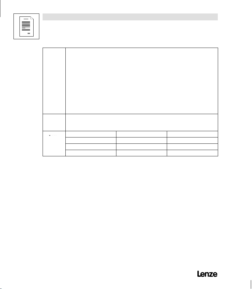
33.820X- E- 1x. 1x (8201 - 8204)
33.8202- E- 1x. 1x -V002 reduced assembly depth (8202)
Type
Design:
B = Module
C=ColdPlate
E = Enclosure IP20
Hardware level and index
Software level and index
Variant
Explanation
кЙоблЙЗ
bЗбнбзе зСW MOLNMLNVVT MVLOMMO
Page 3

Contents
Show/Hide Bookmarks
1 Preface and general information 1-1...........................
1.1 About these Operating Instructions ... 1-1.......................
1.1.1 Terminology used 1-1...............................
1.1.2 What is new? 1-2..................................
1.2 Scope of delivery 1-2.....................................
1.3 Legal regulations 1-3.....................................
2 Safety information 2-1......................................
2.1 General safety information 2-1...............................
2.2 Layout of the safety information 2-3...........................
2.3 Residual hazards 2-4.....................................
3 Technical data 3-1.........................................
3.1 General data/application conditions 3-1.........................
3.2 Rated data (Operation with 150 % overload) 3-2...................
3.2.1 Types 8201 to 8204 3-2.............................
3.3 Fuses and cable cross-sections 3-4...........................
3.3.1 Single drives with 150 % overload 3-4....................
3.4 Dimensions 3-4.........................................
4 Installation 4-1............................................
4.1 Mechanical installation 4-1.................................
4.1.1 Important notes 4-1.................................
4.1.2 Standard assembly with fixing rails or fixing angles 4-3.........
4.1.2.1 Types 8201 to 8204 4-3......................
4.1.2.2 Type 8202-V002 (reduced assembly depth) 4-4.......
4.1.3 DIN-rail assembly 4-5...............................
4.2 Electrical installation 4-6...................................
4.2.1 Important notes 4-6.................................
4.2.2 Power connections 4-7..............................
4.2.2.1 Mains connection 4-7........................
4.2.2.2 Motor connection 4-7........................
4.2.2.3 Connection diagram 4-9.......................
4.2.3 Control connections 4-10..............................
4.2.3.1 Control cables 4-10...........................
4.2.3.2 Assignment of the control terminals 4-10............
4.2.3.3 Connection diagrams 4-12......................
4.3 Installation of a CE-typical drive system 4-13......................
UOMu_^MVMO i
Page 4

Contents
Show/Hide Bookmarks
5 Commissioning 5-1.........................................
5.1 Before you switch on 5-1..................................
5.2 Short set-up (Factory setting) 5-2.............................
5.2.1 Switch-on sequence 5-2.............................
5.2.2 Factory setting of the most important drive parameters 5-3......
5.3 Adapt machine data 5-4...................................
5.3.1 Determine speed range (fdmin, fdmax) 5-4.................
5.3.2 Adjustment of acceleration and deceleration times (Tir , T if) 5-6..
5.3.3 Setting of the current limit (Imax) 5-7.....................
5.4 Optimisation of the operating characteristic of the drive 5-8...........
5.4.1 Select the control mode 5-8...........................
5.4.1.1 Optimisation of V/f-characteristic control
5.4.1.2 Optimisation of V/f-characteristic control 5-13.........
6 During operation 6-1.......................................
7 Configuration 7-1..........................................
7.1 Basics 7-1............................................
7.2 Code table 7-2.........................................
8 Troubleshooting and fault elimination 8-1.......................
8.1 Troubleshooting 8-1......................................
8.1.1 Display at the controller 8-1...........................
8.1.2 Display at the operating module 8-1.....................
8.1.3 Maloperation of the drive 8-2..........................
8.2 Fault analysis using the history buffer 8-2.......................
8.3 Fault indications 8-3......................................
8.4 Reset of fault indications 8-5................................
9 Accessories (Overview) 9-1..................................
9.1 Accessories for all types 9-1................................
9.2 Software 9-2...........................................
9.3 Type-specific accessories 9-2...............................
10 Index 10-1................................................
with auto boost 5-11..........................
ii UOMu_^MVMO
Page 5
Preface and general information
Show/Hide Bookmarks
1 Preface and general information
1.1 About these Operating Instructions ...
D qЬЙлЙ lйЙк~нбеЦ fелнкмЕнбзел ЬЙдй узм нз ЕзееЙЕн ~еЗ лЙн мй
нЬЙ UOuu СкЙимЙеЕу беоЙкнЙкK qЬЙу Езен~бе л~СЙну беСзкг~нбзе
пЬбЕЬ гмлн ДЙ зДлЙкоЙЗK
D ^дд йЙклзел пЬз пзкв зе ~еЗ пбнЬ UOuu СкЙимЙеЕу беоЙкнЙкл
гмлн Ь~оЙ нЬЙ lйЙк~нбеЦ fелнкмЕнбзел ~о~бд~ДдЙ ~еЗ зДлЙкоЙ
~дд кЙдЙо~ен езнЙл ~еЗ белнкмЕнбзелK
D qЬЙ lйЙк~нбеЦ fелнкмЕнбзел гмлн ~дп~ул ДЙ бе ~ ЕзгйдЙнЙ ~еЗ
йЙкСЙЕнду кЙ~З~ДдЙ лн~нЙK
1.1.1 Terminology used
Ter m In the follo wing text used for
82XX Any frequency inverter of the series 8200, 8210, 8220, 8240
Controller 82XX frequency inverter
Drive system Drive systems with 82XX frequency inverters and other Lenze drive
components
UOMu_^MVMO 1-1
Page 6
Preface and general information
Show/Hide Bookmarks
1.1.2 What is new?
Material
no.
375134 05/10/1994 8200/8210 Short Instructions
375190 13/02/1995 8200/8210 Operating Instructions
398283 02/10/1997 replaces 375134
454072 09/2002 replaces 398283 D Chapter 4.2.3.2
Edition of Important Content
replaces 375190
1.2 Scope of delivery
Scope of delivery Important
D 1 82XX frequency inverter
D 1 Operating Instructions
D 1 accessory kit (components for
the mechanical and electric
installation)
D Contents only for 8200
D Complete revision of the contents
D Complete editorial revision
D Chapter 5.1
D Chapter 8.3
D Change of company name
After receipt of the delivery, check immediately whether
the scope of supply matches with the accompanying
papers. Lenze does not accept any liability for deficiencies
claimed subsequently.
Claim
D visible transport damage immediately to the forwarder.
D visible deficiencies/incompleteness immediately to your
Lenze representative.
1-2 UOMu_^MVMO
Page 7
Preface and general information
Labelling
Show/Hide Bookmarks
1.3 Legal regulations
Labelling
Application
as directed
Nameplate CE mark Manufacturer
Lenze controllers are
unambiguously designated by
the content of the nameplate
82XX frequency inverter
D must only be operated under the conditions prescribed in these Instructions.
D are components
- used for open and closed loop control of variable speed drives withasynchronous standard
motors, reluctance motors, PM-synchronous motors with asynchronous damping cage.
- used for installation into a machine.
- used for assembly together with other components to form a machine.
D are electric units for the installation into control cabinets or similar enclosed operating housing.
D comply with the requirements of the Low-Voltage Directive.
D are not machines for the purpose of the Machinery Directive.
D are not to be used as domestic appliances, but only for industrial purposes.
Drive systems with 82XX frequency inverters
D comply with the EMC Directive if they are installed according to the guidelines of CE-typical drive
systems.
D can be used
- on public and non-public mains.
- in industrial as well as residential and commercial premises.
D The user is responsible for the compliance of his application with the EC directives.
Any other use shall be deemed inappropriate!
Conforms to the EC Low Voltage
Directive
Lenze Drive Systems GmbH
Postfach 10 13 52
D-31763 Hameln
UOMu_^MVMO 1-3
Page 8
Preface and general information
Disposa
l
Show/Hide Bookmarks
Liability D The information, data and notes in these Operating Instructions met the state of the art at the time
Warranty D Warranty conditions: see Sales and Delivery Conditions of Lenze Drive Systems GmbH.
Disposal
of printing. Claims referring to drive systems which have already been supplied c annot be derived
from the information, illustrations, and descriptions given in these Operating Instructions.
D The specifications, processes, and circuitry described in these Operating Instructions are for
guidance only and must be adapted to your own specific application. Lenze does not take
responsibility for the suitability of the process and circuit proposals.
D The indications given in these Operating Instructions describe the features of the product without
warranting them.
D Lenze does not accept any liability for damage and operating interference caused by:
- disregarding these Instructions
- unauthorized modifications to the controller
- operating errors
- improper working on and with the controller
D Warranty claims must be made immediately after detecting defects or faults.
D The warranty is void in all cases where liability claims cannot be made.
Material recycle dispose
Metal D Plastic D Printed-board assemblies - D
1-4 UOMu_^MVMO
Page 9
Safety information
Show/Hide Bookmarks
2 Safety information
2.1 General safety information
Safety and application notes for controllers
EнзW iзпJsздн~ЦЙ aбкЙЕнбоЙ TPLOPLbb`F
1. General
During operation, drive controllers may have, according
to their type of protection, live, bare, in some cases also
movable or rotating parts as well as hot surfaces.
Non-authorized removal of the required cover,
inappropriate use, incorrect installation or operation,
creates the risk of severe injury to persons or damage to
material assets.
Further information can be obtained from the
documentation.
All operations concerning transport, installation, and
commissioning as well as maintenance must be carried
out by qualified, skilled personnel (IEC 364 and CENELEC
HD 384 or DIN V DE 0100 and IEC report 664 or DIN VDE
0110 and national regulations for the prevention of
accidents must be observed).
According to this basic safety information qualified
skilled personnel are persons who are familiar with the
erection, assembly, commissioning, and operation of the
product and who have the qualifications necessary for
their occupation.
2. Application as directed
Drive controllers are components which are designed for
installation in electrical systems or machinery.
When installing in machines, commissioning of the drive
controllers (i.e. the starting of operation as directed) is
prohibited until it is proven that the machine corresponds
to the regulations of the EC Directive 89/392/EEC
(Machinery Directive); EN 60204 must be observed.
Commissioning (i.e. starting of operation as directed) is
only allowed when there is compliance with the EMC
Directive (89/336/EEC).
The drive controllers meet the requirements of the Low
Voltage Directive 73/23/EEC. The harmonized standards
of the prEN 50178/ DIN VDE 0160 series together with
EN 60439-1/DIN VDE 0660 part 500 and EN 60146/DIN
VDE 0558 are applicable to drive controllers.
The technical data and information on the connection
conditions must be obtained from the nameplate and the
documentation and must be observed in all cases.
3. Transport, storage
Notes on transport, storage and appropriate handling
must be observed.
Climatic conditions must be observed according to
prEN 50178.
4. Erection
The devices must be erected and cooled according to the
regulations of the corresponding documentation.
The drive controllers must be protected from
inappropriate loads. Particularly during transport and
handling, components must not be bent and/or isolating
distances must not be changed. Touching of electronic
components and contacts must be avoided.
UOMu_^MVMO 2-1
Page 10

Safety information
Show/Hide Bookmarks
Drive controllers contain electrostatically sensitive
components which can easily be damaged by
inappropriate handling. Electrical components must not
be damaged or destroyed mechanically (health risks are
possible!).
5. Electrical connection
When working on live drive controllers, the valid national
regulations for the prevention of accidents (e.g. VBG 4)
must be observed.
The electrical installation must be carried out according
to the appropriate regulations (e.g. cable cross-sections,
fuses, PE connection). More detailed information is
included in the documentation.
Notes concerning the installation in compliance with
EMC - such as screening, grounding, arrangement of
filters and laying of cables - are included in the
documentation of the drive controllers. These notes must
also be observed in all cases for drive controllers with
the CE mark. The compliance with the required limit
values demanded by the EMC legislation is the
responsibility of the manufacturer of the system or
machine.
6. Operation
Systems where drive controllers are installed must be
equipped, if necessary, with additional monitoring and
protective devices according to the valid safety
regulations, e.g. law on technical tools, regulations for
the prevention of accidents, etc. Modifications of the
drive controllers by the operating software are allowed.
After disconnecting the drive controllers from the supply
voltage, live parts of the controller and power
connections must not be touched immediately, because
of possibly charged capacitors. For this, observe the
corresponding labels on the drive controllers.
During operation, all covers and doors must be closed.
7. Maintenance and servicing
The manufacturer’s documentation must be observed.
This safety information must be kept!
The product-specific safety and application notes
in these Operating Instructions must also be
observed!
2-2 UOMu_^MVMO
Page 11
Safety information
Show/Hide Bookmarks
2.2 Layout of the safety information
D ^дд л~СЙну езнЙл Ь~оЙ ~ мебСзкг д~узмнW
J qЬЙ бЕзе ЕЬ~к~ЕнЙкбтЙл нЬЙ нуйЙ зС З~еЦЙкK
J qЬЙ лбЦе~д пзкЗ ЕЬ~к~ЕнЙкбтЙл нЬЙ лЙоЙкбну зС З~еЦЙкK
J qЬЙ езнЙ ЗЙлЕкбДЙл нЬЙ З~еЦЙк ~еЗ лмЦЦЙлнл Ьзп нз ~озбЗ
íÜÉ Ç~åÖÉêK
Signal word
kçíÉ
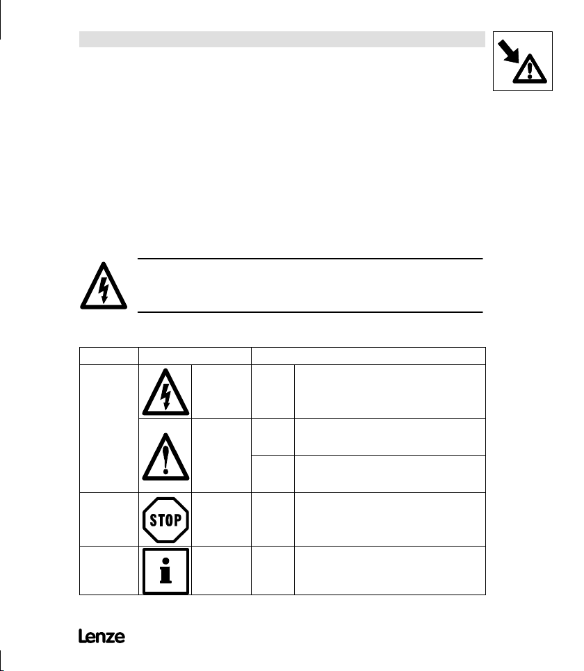
Icons used Signal words
Warning of
danger to
persons
Warning of
damage to
material
Other notes Note! This note designates general, useful notes.
Warning of
hazardous
electrical
voltage
Warning of a
general danger
Danger! Warns of impending danger.
Warning! Warns of potential, very hazardous situations.
Caution! Warns of potential, hazardous situations.
Stop! Warns of potential damage to material .
Consequences if disregarded:
Death or very severe injuries.
Possible consequences if disregarded:
Death or very severe injuries.
Possible consequences if disregarded:
Light or minor injuries.
Possible consequences if disregarded:
Damage of the controller/drive system or its
environment
If you observe it, handling of the controller/drive
system is made easier.
K
UOMu_^MVMO 2-3
Page 12
Safety information
Show/Hide Bookmarks
2.3 Residual hazards
Operator’s safety After mains disconnections, the power terminals U, V, W and +UG,-UGremain live for at
Protection of
devices
Overspeeds Drive systems can reach dangerous overspeeds (e. g. setting of inappropriately high field
least three minutes.
D Before working on the controller, check that no voltage is applied to the power terminals.
Cyclic connection and disconnection of the controller supply voltage at L1, L2, L3 or +U
may overload the internal input current load:
-U
G
D Allow at least 3 minutes between disconnection and reconnection.
frequencies):
D The controllers do not offer any protection against these operating conditions. Use
additional components for this.
,
G
2-4 UOMu_^MVMO
Page 13
Technical Data
Permissible
Show/Hide Bookmarks
3 Technical data
3.1 General data/application conditions
Field Values
Vibration resistance Germanischer Lloyd, general conditions
Humidity class Humidity class F without condensation (average relative humidity 85 %)
Permissible
temperature ranges
Permissible
installation height h
Degree of pollution VDE 0110 part 2 pollution degree 2
Noise emission Requirements acc. to EN 50081-2, EN 50082-1, IEC 22G-WG4 (Cv) 21
Noise immunity
Insulation strength Overvoltage category III according to VDE 0110
Packaging
(DIN 4180)
Type of protection IP20
Approvals CE: Low Voltage Directive
during transport of the controller: -25 °C ¼ +70 °C
during storage of the controller: -25 °C ¼ +55 °C
during operation of the controller: 0 °C ¼+40 °C
h ≤ 1000 m.a.m.s.l
1000 m a.m.s.l
Limit value class A to EN 55011 (industrial area) with mains filter
Limit value class B to EN 55022 (residential area) with mains filter and installation into
control cabinet
Limit values maintained usig mains filter
Requirements according to EN 50082-2, IEC 22G-WG4 (Cv) 21
Requirements Standard Severities
ESD EN61000-4-2 3, i.e. 8 kV with air discharge
RF interference(enclosure) EN61000-4-3 3, i.e. 10 V/m; 27¼1000 MHz
Burst EN61000-4-4 3/4, i.e. 2 kV/5 kHz
Surge
(Surge on mains cable)
< h ≤ 4000 m a.m.s.l
+40
°C ¼ +50 °C
EN 61000-4-5 3, i.e. 1.2/50 μs,
Dust packaging
NEMA 1: Protection against contact
without power derating
with power derating
without power derating
with power derating
6 kV with contact discharge
1 kV phase-phase,
2 kV phase-PE
Electromagnetic compatibility
UOMu_^MVMO 3-1
Page 14
Technical Data
Variantreducedassembl
y
otopoe(poeS
)
Show/Hide Bookmarks
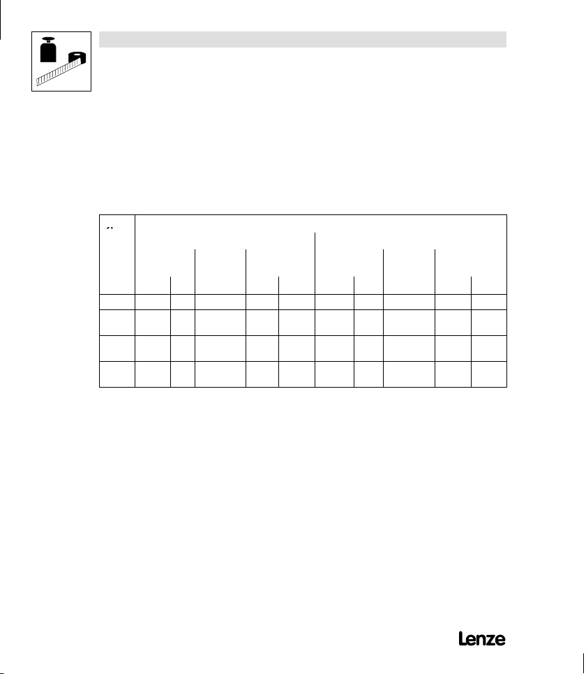
3.2 Rated data (Operation with 150 % overload)
3.2.1 Types 8201 to 8204
150 % overload Type 8201 8202 8203 8204
Order no. EVF8201-E EVF8202-E EVF8203-E EVF8204-E
Variant ”reduced assembly
depth”
Type 8202-V002
Order no. EVF8202-E- V002
3-2 UOMu_^MVMO
Mains voltage V
Alternative DC supply VDC[V] 270V 0% ≤ V
Mains current
4)
with mains filter/mains choke
without mains filter/mains choke
Data for mains operation with 1 AC / 230 V / 50 Hz/60 Hz; 270 ≤ V
Motor power (4 pole ASM)
at 9.2 kHz*
Output power U, V, W
at 9.2 kHz*
Output power +UG,-U
1)
G
Output current I
Max. output current for 60s
Motor voltage
3)
2)
[V] 190V 0% ≤ V
rated
I
[A]
mains
4.2
5.0
P
[kW] 0.37 0.75 1.5 2.2
rated
P
[hp] 0.5 1.0 2.0 2.9
rated
S
[kVA] 1.0 1.5 2.7 3.6
N9.2
≤ 260V 0% ; 45Hz¼65Hz 0%
rated
7.5
9.0
DC
DC
≤ 275V
≤ 360V 0%
12.5
15.0
PDC[kW] 0.0 0.0 0.0 0.0
[A] 2.6 4.0 7.0 9.5
rated
I
[A] 3.9 6.0 10.5 14.2
Nmax
VM[V] 0-3× V
/0Hz¼ 50Hz, if required up to 240Hz
mains
17.0
Power loss (Operation with IN) Pv[W] 30 50 70 100
-
Page 15
150 % overload 8204820382028201Type
Field
Analogsetpoin
t
Show/Hide Bookmarks
Variant ”reduced assembly
depth”
depth”
Technical Data
EVF8204-EEVF8203-EEVF8202-EEVF8201-EOrder no.
8202-V002TypeVariant ”reduced assembly
EVF8202-E- V002Order no.
Power derating [%/K]
[%/m]
Field
frequency
Resolution Absolute 0.05 Hz
Digital setpoint
selection
Analog setpoint
selection
Accuracy 0.05 Hz
Linearity 0.5 % (max. selected signal level, 5V or 10V)
Temperature
sensitivity
40 °C<T
1000 m a.m.s.l.
Offset 0.3 %
Weight m[kg] 1.0 1.3
Variant 1.0
1)
2)
3)
4)
This power can be additionally obtained when operating a matching motor
The currents apply to a periodical load cycle with 1 minute overcurrentwith the current mentioned here
and 2 minutes base load with 75% I
With mains choke/mains filter: max. output voltage = approx. 96 % of the mains voltage
Nrated
.
Observe the N-conduction load when having a symmetrical mains distribution!
(See electrical installation)
* Chopper frequency of the inverter
<50°C: 2,5%/K
amb
< h ≤ 4000 m a.m.s.l.: 5%/1000 m
0 ¼ 40 °C: +0.4 %
2.2 2.2
UOMu_^MVMO 3-3
Page 16
Technical Data
Typ
e
Show/Hide Bookmarks
3.3 Fuses and cable cross-sections
3.3.1 Single drives with 150 % overload
qЬЙ н~ДдЙ о~дмЙл ~кЙ о~дбЗ Сзк нЬЙ зйЙк~нбзе зС UOuu ЕзенкзддЙкл ~л
лбеЦдЙ ЗкбоЙл пбнЬ ~ г~нЕЬбеЦ гзнзк ~еЗ NRM B зоЙкдз~ЗK
Mains input L1, N, PE / motor connection U, V, W, PE
Type
Operation without mains filter/mains choke Operation with mains filter/mains choke
Fuse
F1, F2, F3
VDE UL VDE mm2AWG VDE UL VDE mm2AWG
8201 M 10A - C 10A 1.5 15 M 10A - C 10A 1.5 15
8202 M 15A - C 16A 2.5 13 M 15A - C 16A 2.5
8203 M 20A - C 20A 4 11 M 15A - C 16A 2.5
8204 - - - - - M 20A - C 20A 4
Values in square brackets are valid for motor connection
1)
E.l.c.b. Cable
Observe national and regional regulations (e. g. VDE/EVU)!
cross-section
1)
Fuse
F1, F2, F3
E.l.c.b. Cable
cross-section
[1.5]13[15]
[1.5]13[15]
[2.5]11[13]
1)
3-4 UOMu_^MVMO
3.4 Dimensions
qЬЙ ЕзенкзддЙк ЗбгЙелбзел ЗЙйЙеЗ зе нЬЙ гЙЕЬ~ебЕ~д белн~дд~нбзе
EлЙЙ ЕЬ~йнЙк QKNFK
Page 17

4 Installation
Show/Hide Bookmarks
4.1 Mechanical installation
4.1.1 Important notes
D rлЙ нЬЙ ЕзенкзддЙкл зеду ~л ДмбднJбе ЗЙобЕЙл>
D fС нЬЙ ЕзздбеЦ ~бк Езен~бел йзддмн~енл EЗмлнI СдмССI ЦкЙ~лЙI
~ЦЦкЙллбоЙ Ц~лЙлFW
J н~вЙ лмбн~ДдЙ йкЙоЙенбоЙ гЙ~лмкЙл I ЙKЦK лЙй~к~нЙ ~бк ЗмЕнI
белн~дд~нбзе зС СбднЙклI кЙЦмд~к ЕдЙ~ебеЦI ЙнЕK
D lДлЙкоЙ СкЙЙ лй~ЕЙ>
J vзм Е~е белн~дд лЙоЙк~д ЕзенкзддЙкл еЙсн нз Й~ЕЬ знЬЙк
пбнЬзмн СкЙЙ лй~ЕЙ бе ~ Езенкзд Е~ДбеЙнK
J bелмкЙ мебгйЙЗЙЗ оЙенбд~нбзе зС ЕзздбеЦ ~бк ~еЗ змндЙн зС
ÉñÜ~ìëí ~áê>
J ^ддзп ~ СкЙЙ лй~ЕЙ зС NMM гг ~н нЬЙ нзй ~еЗ ~н нЬЙ ДзннзгK
D aз езн ЙсЕЙЙЗ нЬЙ ~гДбЙен нЙгйЙк~нмкЙ йЙкгбллбДдЙ ЗмкбеЦ
çéÉê~íáçå EëÉÉ ÅÜ~éíÉêK PKNF
D tбнЬ Езенбезмл злЕбдд~нбзел зк обДк~нбзелW
J `ЬЙЕв пЬЙнЬЙк лЬзЕв ~ДлзкДЙкл ~кЙ еЙЕЙлл~куK
Installation
UOMu_^MVMO 4-1
Page 18

Installation
Show/Hide Bookmarks
Possible mounting positions
D fе оЙкнбЕ~д йзлбнбзе ~н нЬЙ Д~Ев зС нЬЙ Езенкзд Е~ДбеЙнI
нЙкгбе~дл йзбен нз нЬЙ СкзенW
J tбнЬ ~нн~ЕЬЙЗ СбсбеЦ к~бдлK
J tбнЬ лйЙЕб~д СбсбеЦ мебн зе зеЙ зк нпз afk к~бдлK
D qìê å É Ç Ä ó VM ° EСд~н ~ллЙгДду зе нЬЙ Д~ЕвлбЗЙ зС нЬЙ Езенкзд
Е~ДбеЙнFW
J fелЙкн нЬЙ ~нн~ЕЬЙЗ СбсбеЦ к~бд бенз нЬЙ ЦмбЗЙл ~н нЬЙ ЬЙ~н
D eзкбтзен~дду пбнЬ ~е ~ЗЗбнбзе~д С~еK
D lе ~ йбознбеЦ Ск~гЙ Сзк ~ллЙгДду ЗЙйнЬл Y NVU ггW
J qЬЙкЙСзкЙ Й~лу Ь~еЗдбеЦ ~еЗ белн~дд~нбзе зС нЬЙ Скзен
ëáåâK
бенЙкС~ЕЙл йзллбДдЙK
4-2 UOMu_^MVMO
Page 19
Installation
g
Typ
Id.-NR
Fert.-Nr
Serien-Nr.
Eingang1
Eingang2
Lenze
Postfach101352,31763 HAMELN
c
k
a
e
db
1)
2)
3)
Show/Hide Bookmarks
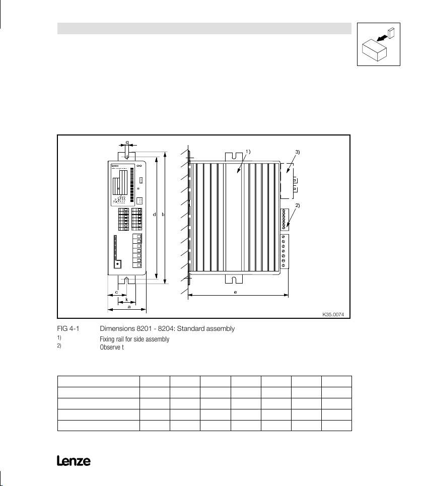
4.1.2 Standard assembly with fixing rails or fixing angles
4.1.2.1 Types 8201 to 8204
cfd QJN aбгЙелбзел UOMN J UOMQW pн~еЗ~кЗ ~ллЙгДду
1)
2)
3)
[mm]
8201 64 210 29 190 158 6.5 30
8202 64 210 29 190 198 6.5 30
8202- V002 64 210 29 190 158 6.5 30
8203 / 8204 83 283 38 263 211 6.5 30
Fixing rail for side assembly
Observe the free space required for the connection cables
With attachable fieldbus or I/O module:
Observe assembly depth and assembly space required for connection cables
a b c d e
3)
hPRKMMTQ
g k
UOMu_^MVMO 4-3
Page 20

Installation
Show/Hide Bookmarks
4.1.2.2 Type 8202-V002 (reduced assembly depth)
qЬбл о~кб~ен бл ЙимбййЙЗ пбнЬ ~ ЬЙ~н лбев пбнЬ ~ лг~ддЙк лмкС~ЕЙK
lДлЙкоЙ нЬЙ СзддзпбеЦ йзбенл нз Езгйду пбнЬ нЬЙ нЙЕЬебЕ~д З~н~W
D ^ллЙгДду зе ~е мей~бенЙЗI гЙн~ддбЕ ~ллЙгДду Дз~кЗK
D ^êÉ~ [ MKNR ã
D pЬЙЙн нЬбЕвеЙлл ~н дЙ~лн O ггK
O
K
4-4 UOMu_^MVMO
Page 21
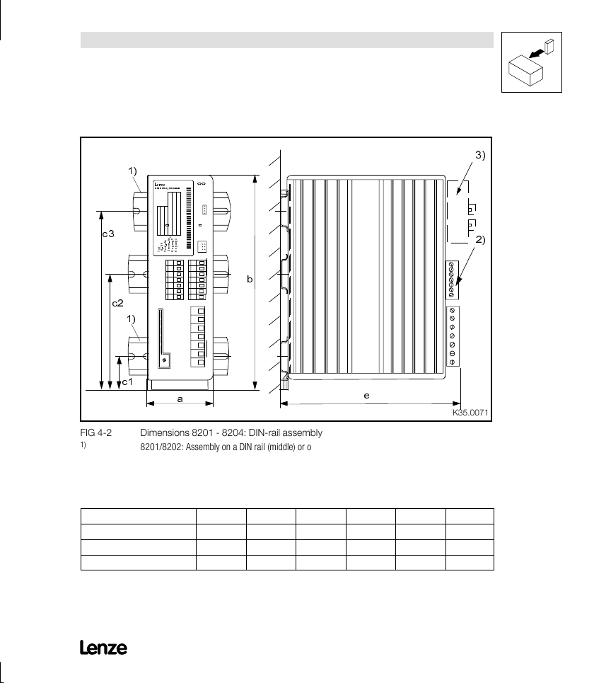
4.1.3 DIN-rail assembly
Show/Hide Bookmarks
1)
Lenze
Postfach101352,31763HAMELN
Installation
3)
c3
Typ
Id.-NR
Fert.-Nr
Serien-N r.
Eingang1
Eingang2
b
c2
1)
c1
a
cfd QJO aбгЙелбзел UOMN J UOMQW afkJк~бд ~ллЙгДду
1)
2)
3)
8201/8202: Assembly on a DIN rail (middle) or on two DIN rails (top and bottom) possible
8203 - 8204: Assembly on two DIN rails
Observe the free space required for the connection cables
With attachable fieldbus or I/O module:
e
Observe assembly depth and assembly space required for connection cables
[mm]
a b c1 c2 c3 e
8201 64 188 16 98 149 173
8202 64 188 16 98 149 213
8203 / 8204 83 258 16 - 149 237
2)
hPRKMMTN
3)
UOMu_^MVMO 4-5
Page 22
Installation
Show/Hide Bookmarks
4.2 Electrical installation
4.2.1 Important notes
D bелмкЙ ~ййкзйкб~нЙ ~Енбо~нбзе пЬЙе млбеЦ ЕмккЙенJзйЙк~нЙЗ
ÉKäKÅKÄKëK
D cзк беСзкг~нбзе зе нЬЙ белн~дд~нбзе ~ЕЕзкЗбеЦ нз bj` лЙЙ
ÅÜ~éíÉê QKP
D mкбзк нз ~ллЙгДду ~еЗ лЙкобЕЙ зйЙк~нбзелI нЬЙ йЙклзееЙд гмлн
ДЙ СкЙЙ зС ЙдЙЕнкзлн~нбЕ ЕЬ~кЦЙK
D rемлЙЗ Езенкзд беймнл ~еЗ змнймнл лЬзмдЗ ДЙ ЕзоЙкЙЗ пбнЬ
йдмЦлK
D fе Е~лЙ зС ЕзеЗЙел~нбзеI ЕзееЙЕн нЬЙ ЕзенкзддЙк нз нЬЙ г~бел
оздн~ЦЙ зеду ~СнЙк нЬЙ облбДдЙ ЬмгбЗбну Ь~л Йо~йзк~нЙЗK
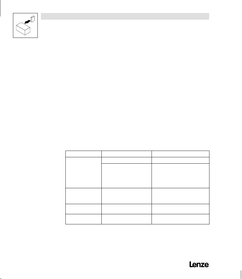
D mдЙ~лЙ зДлЙкоЙ нЬЙ кЙлнкбЕбнзел зС Й~ЕЬ г~бел нуйЙ>
Mains Operation of the controller Notes
With grounded neutral No restrictions Observe controller ratings
With isolated neutral
(IT mains)
With grounded phase Operation only possible with one
DC supply via +UG/-UG DCvoltagemustbesymmetrical
Operation of several 820X
controllers connected to a mains
3AC / N / PE and symmetrical
distribution to the three outer
conductors excepted
Operation with recommended
mainsfiltersisnotpossible
variant
to PE
D Observe the load of the shared
N-conductor.
- r.m.s. current, see chapter 3.2
D Possibly enlarge the cross-section
of the N-conductor.
D Mains filter will be destroyed if
”earth fault” occurs.
D Contact Lenze.
Contact Lenze
Controller will be destroyed when
grounding +U
G-Leiteror-UG-Leiter
4-6 UOMu_^MVMO
Page 23

4.2.2 Power connections
Show/Hide Bookmarks
4.2.2.1 Mains connection
D `зееЙЕн нЬЙ г~бел Е~ДдЙл пбнЬ нЬЙ лЕкЙп нЙкгбе~дл
iNI iOI iPK
J qбЦЬнЙебеЦ нзкимЙл
Type
8201 - 8204 0.5 ... 0.6 Nm (4.4 ... 5.3 lbin) 3.4 Nm (30 lbin)
L1,L2,L3,+UG,-UG PE connection
4.2.2.2 Motor connection
_ЙЕ~млЙ зС нЬЙ bj` л~СЙну пЙ кЙЕзггЙеЗ нЬЙ млЙ зС лЕкЙЙеЙЗ
гзнзк Е~ДдЙл зедуK
pЕкЙЙе ЕзееЙЕнбзе
D UOMuW lе нЬЙ Скзен c^pqJlk ЕзееЙЕнзкK
D `зееЙЕн нЬЙ гзнзк Е~ДдЙл нз нЬЙ лЕкЙп нЙкгбе~дл rI sI t
~елЕЬдбЙ≈ЙеK
J lДлЙкоЙ ЕзккЙЕн йздЙ ЕзееЙЕнбзеK
J qбЦЬнЙебеЦ нзкимЙл
Type
8201 -
8204
U, V, W PE connection
0.5 ... 0.6 Nm
(4.4 ... 5.3 lbin)
3.4 Nm
(30 lbin)
Ter mi nal s
Ter mi nal s
Installation
Screen/
strain relief
- -
T1, T2
D pпбнЕЬбеЦ зе нЬЙ гзнзк лбЗЙ зС нЬЙ ЕзенкзддЙк бл йЙкгбннЙЗ
J Сзк л~СЙну лпбнЕЬ зСС EЙгЙкЦЙеЕу лпбнЕЬ зССFK
J ЗмкбеЦ зйЙк~нбзе меЗЙк дз~ЗK
UOMu_^MVMO 4-7
Page 24

Installation
-0-,-1-
-2-,-3-
-2-,-3-
,
Show/Hide Bookmarks
D qЬЙ гзнзк Е~ДдЙ лЬзмдЗ ДЙ ~л лЬзкн ~л йзллбДдЙ ДЙЕ~млЙ зС
нЬЙ йзлбнбоЙ ЙССЙЕн зе нЬЙ ЗкбоЙ ЕЬ~к~ЕнЙкблнбЕK
J cfd QJP лЬзпл нЬЙ кЙд~нбзе ДЙнпЙЙе гзнзкJЕ~ДдЙ дЙеЦнЬ
~еЗ нЬЙ йзллбДдЙ кЙимбкЙЗ змнймн СбднЙклK
J cзк Цкзмй ЗкбоЙл EлЙоЙк~д гзнзкл ЕзееЙЕнЙЗ нз зеЙ
ЕзенкзддЙкF бн бл еЙЕЙлл~ку нз Е~дЕмд~нЙ нЬЙ кЙлмднбеЦ Е~ДдЙ
дЙеЦнЬ д
fêÉë = pмг зС ~дд гзнзк Е~ДдЙ дЙеЦнЬл ⋅ kзK зС гзнзк Е~ДдЙл
J tЬЙе млбеЦ мелЕкЙЙеЙЗ гзнзк Е~ДдЙлI нЬЙ З~н~ беЗбЕ~нЙЗ
бе cfd QJP ~кЙ о ~дбЗ Сзк нЬЙ ЗзмДдЙ гзнзкJЕ~ДдЙ дЙеЦнЬK
J mдЙ~лЙ Езен~Ен iЙетЙ пЬЙе нЬЙ ~ДлздмнЙ зк кЙлмднбеЦ
гзнзкJЕ~ДдЙ дЙеЦнЬл ~кЙ [ OMM гK
Type Permissible control mode C014
8201
8202
8203
8204
Motor-cable length (resulting), s creened in m
cfd QJP lмнймн СбднЙкл ~ЗЗбнбзе~дду кЙимбкЙЗ бе нЬЙ гзнзк Е~ДдЙ
-0-, -1-,
,
-2-, -3-
0 15 25 50 100 200
êÉë
-2-, -3-
W
-2-, -3- -2-, -3-
+ motor filter/
+ sine filter
4-8 UOMu_^MVMO
Page 25

4.2.2.3 Connection diagram
Show/Hide Bookmarks
L1
N/L2
PE
K10
J
K10
PE
PE
RB1 RB2
Z3
F1 F2*
L1
+UG
8201... 8204
-UG
PE
UVW
N
K10*
PE
K10
R
B
Z1
RB
+UG
-UG
Installation
F1 Fuse
F2* Fuse only for supply with 2AC / PE /
190-260V
K10 Mains contactor
K10* Mains contactor only for supply
with 2AC / PE / 190-260V
Z1 Mains filter/mains choke, see
Accessories
Z2 Motor filter/sine filter, see
Accessories
Z3 Brake chopper/brake module, see
Accessories
RB Brake resistor, see Accessories
J
Temperature monitoring - brake
RB
resistor
X1 Terminal strip in control cabinet
8204 operation only with assigned
mains choke/mains filter
cfd QJQ UOMu йзпЙк ЕзееЙЕнбзел
PE
Z2
-X1
M
3~
PE
hPRKMNPR
UOMu_^MVMO 4-9
Page 26

Installation
Show/Hide Bookmarks
4.2.3 Control connections
4.2.3.1 Control cables
D tЙ кЙЕзггЙеЗ нЬЙ мебд~нЙк~д лЕкЙЙебеЦ зС ~дд Е~ДдЙл Сзк
~е~дзЦ лбЦе~дл нз ~озбЗ лбЦе~д ЗблнзкнбзеK
D `зееЙЕн нЬЙ лЕкЙЙел зС нЬЙ Езенкзд Е~ДдЙл ~л СзддзплW
J UOMuW
lе нЬЙ Скзен c^pqJlk ЕзееЙЕнзкK
D fС нЬЙ Езенкзд Е~ДдЙл ~кЙ бенЙккмйнЙЗ EнЙкгбе~д лнкбйлI кЙд~улFI
нЬЙ лЕкЙЙел гмлн ДЙ кЙЕзееЙЕнЙЗ зоЙк нЬЙ лЬзкнЙлн йзллбДдЙ
Зблн~еЕЙK
D `зеееЙЕн нЬЙ СбсбеЦ лЕкЙп зС нЬЙ лЙнйзбен йзнЙенбзгЙнЙк нз
mbK
4.2.3.2 Assignment of the control terminals
6 2
7
8
9
K 1 1
K 1 2
K 1 4
cfd QJR mзлбнбзе зС нЬЙ Езенкзд нЙкгбе~дл
4-10 UOMu_^MVMO
2 0
2 8
E 1
E 2
E 3
E 4
3 9
hPRKMMOS
Page 27

Installation
R
P
Vol
t
100
k
Ω
p
HIGH:12V...30
V
JOGequece
s
aycod
e
p
60VDC/0.5
A
Show/Hide Bookmarks
Ter mi nal Use
Analog
7 GND 1
inputs
8 Setpoint input,
9 Supply for setpoint potentiometer 5.2V / 6mA
Analog
62 Analog output, reference: terminal 7
output
Digital
20 Voltage supply for digital inputs
inputs
28 Controller enable HIGH
E4 CW rotation/
E3 DC-injection brake HIGH
E2
E1
39 GND 2 (reference for external voltages)
Ter mi nal Use
Relay
K11 Relay output normally-closed contact
output
K1
K12 Relay mid-position contact
K14 Relay output normally-open contact
(Factory setting is printed in bold)
reference:
Ter min al 7
(0 to 10V)
(Field frequency)
12 V/20 mA
CCW rotation (CW/CCW)
JOG frequencies Binary code
20Hz, 30Hz, 40Hz
(Factory setting is printed in bold)
(TRIP)
(TRIP)
S
Q
O
Jumper
Level Data
5-6
0to20mA
5-6
4to20mA
3-4
0to5V
1-2
0to10V
N
0... 6 V / 2mAResolution: 8 bit
CW: LOW
CCW: HIGH
Relay position
(switched)
opened
closed
Resolution: 9 bit
Linearity fault:
Temperature fault: 0.3 % (0...+40
°C)
Input resistance
Current signal: 250 Ω
HIGH: 12 V ... 30 V
LOW: 0V...3V
±0.5 %
age signal:>
Data
24 V AC / 3,0 A or
60 V DC / 0.5 A
UOMu_^MVMO 4- 11
Page 28

Installation
Show/Hide Bookmarks
4.2.3.3 Connection diagrams
82XX
PE
GND 1
3k3
>100k
62789
K1
Vref
5,2V
K14
K11K12
3k3k
Vcc
2028E1E2E3 E4
GND 2
3k
3k3k
39
cfd QJS `зенкзд ЕзееЙЕнбзелW pмййду пбнЬ бенЙке~д Езенкзд оздн~ЦЙ
cfd QJT `зенкзд ЕзееЙЕнбзелW bснЙке~д оздн~ЦЙ лмййду EHNO s KKK HPM sF
GND1 Reference for internal voltages
GND2 Reference for external voltages
4-12 UOMu_^MVMO
R ³ 1k
82XX
PE
GND 1
3k3
>100k
62 789
R ³ 1k
Vref
5,2V
K11K1 2K14
K1
3k
Vcc
20 28 E1 E2 E3 E4 39
GND1 and GND2 have a potential isolation inside the unit.
hPRKMMTTJP
GND 2
3k3k3k
3k
-
12...30V
+
hPRKMMTTJQ
Page 29

Installation
Show/Hide Bookmarks
4.3 Installation of a CE-typical drive system
General
notes
Assembly D Connect controller, mains choke, and mains filter to the grounded mounting plate with a wire of
Filters D Use mains filters or RFI filters and mains chokes which are assigned to the controller:
D The user is responsible for the compliance of his application with the EC directives.
- If you observe the following measure you can be sure that the drive system will not cause any
EMC problems, i.e. comply with the EMC Directive when running the machine.
- If devices which do not comply with the CE requirement concerning noise immunity EN 50082-2
are operated close to the controller, these devices may be interfered electromagnetically by the
controllers.
large a cross-section as possible:
- Mounting plates with conductive surfaces (zinc-coated, stainless steel) allow permanent contact.
- Varnished boards should not be used for installation in accordance with EMC
D If you use several mounting plates:
- Connect as much surface as possible of the mounting plates (e.g. with copper bands).
D Ensure the separation of motor cable and signal or mains cable.
D Do not use the same terminal strip for mains input and motor output.
D Cable guides as close as possible to the reference potential. Unguided cables have the same effect
as aerials.
- RFI filters reduce impermissible high-frequency interference to a permissible value.
- Mains chokes reduce low-frequency interferences which depend on the motor cable and its
length.
- Mains filters combine the functions of mains choke and RFI filter.
UOMu_^MVMO 4- 13
Page 30

Installation
Show/Hide Bookmarks
Screening D Connect the screen of the motor cable with the controller
Grounding D Ground all conductive metal components (controller, mains filter, motor filter, mains choke) using
- to the screen connection of the controller.
- additionally to the mounting plate with a surface as large as possible.
- Recommendation: For the connection, use ground clamps on bare metal mounting surfaces.
D If contactors, motor-protecting switches or terminals are located in the motor cable:
- Connect the screens of the connected cables also to the mounting plate, with a surface as large
as possible.
D Connect the screen to PE, with a surface as large as possible.
- Metal glands at the motor terminal box ensure a connection of the screen and the motor
housing.
D If the mains cable between mains filter and controller is longer than 300 mm:
- Screen mains cables.
- Connect the screen of the mains cable directly to the inverter and to the mains filter and connect
it to the mounting plate with as large a surface as possible.
D Use of a brake chopper:
- Connect the screen of the brake resistor cable directly to the mounting plate, at the brake
chopper and the brake resistor with as large a surface as possible.
- Connect the screen of the cable between controller and brake chopper directly to the mounting
plate, at the inverter and the brake chopper with a surface as large as possible.
D Screen the control cables:
- Connect both screen ends of the digital control cables.
- Connect one screen end of the analog control cables.
- Always connect the screens to the screen connection at the controller over the shortest possible
distance.
D Application of the controllers 821X/822X/824X in residential areas:
- Use an additional screen damping
achieved by installation in enclosed and grounded control cabinets made of metal.
suitable cables connected to a central point (PE bar).
D Maintain the minimum cross-sections prescribed in the safety regulations:
- For EMC, not the cable cross-section is important, but the surface and the contact with a
cross-section as large as possible, i.e. large surface.
³ 10 dB to limit the radio interference. This is usually
4-14 UOMu_^MVMO
Page 31

Installation
Show/Hide Bookmarks
RB1RB2 +UG
Z3
n
n
n
F1
n
K10
n
Z1
n
n
PE
PES
RB
-UG
PES
PE
Lx
PES
+UG
-UG
PE
UVW
PE
Z2
-X1
M
PE
3~
82XX
GND 1
789
62
PES
PES
K1
Vref
Vcc
K11
K12K14
2028E1
GND 2
E4 39
E2
E3
PES
PE
Netz
PE
PE
PES
PES PES
PE
cfd QJU bс~гйдЙ Сзк ~е белн~дд~нбзе бе ~ЕЕзкЗ~еЕЙ пбнЬ нЬЙ bj` кЙЦмд~нбзелW
F1 Fuse
K10 Mains contactor
Z1 Mains filter ”A” or ”B”, see Accessories
Z2 Motor filter/sine filter, see Accessories
Z3 Brake module/brake chopper, see Accessories
-X1 Terminal strip in control cabinet
RB Brake resistor
PES HF screen because of a PE connection with a surface as large as possible
(see ”Screening” in this chapter)
n Number of phases
PES
PES
hPRKMMUO
UOMu_^MVMO 4- 15
Page 32

Installation
Show/Hide Bookmarks
4-16 UOMu_^MVMO
Page 33

5 Commissioning
Show/Hide Bookmarks
qЬЙ ЕзенкзддЙкл ~кЙ С~ЕнзкуJлЙн нз ЗкбоЙ ~ ЕзккЙлйзеЗбеЦ СзмкJйздЙ
лн~еЗ~кЗ гзнзк пбнЬ OPMLQMMsI RMeтK cмкнЬЙк лЙннбеЦл ~кЙ езн
еЙЕЙлл~куK
lеду ~ СЙп лЙннбеЦл об~ нЬЙ UOMN __ зйЙк~нбеЦ гзЗмдЙ зк ~ СбЙдЗДмл
гзЗмдЙ ~кЙ еЙЕЙлл~ку нз ~З~йн узмк ЗкбоЙ нз узмк ~ййдбЕ~нбзеK qЬЙ
лнЙйл кЙимбкЙЗ ~кЙ лмгг~кбтЙЗ бе ЕЬ~йнЙк RKP ~еЗ бе ЕЬ~йнЙк RKQK
5.1 Before you switch on
mкбзк нз бебнб~д лпбнЕЬJзе зС нЬЙ ЕзенкзддЙкI ЕЬЙЕв нЬЙ пбкбеЦ Сзк
ЕзгйдЙнЙеЙллI лЬзкнJЕбкЕмбнI ~еЗ Й~кнЬ С~мднW
D mзпЙк ЕзееЙЕнбзеW
J sб~ нЙкгбе~дл iNLk J UOMuK
J ^днЙке~нбоЙду об~ нЙкгбе~дл HrdI Jrd Ea`JЦкзмй ЗкбоЙF
D `зенкзд нЙкгбе~длW
J oЙСЙкЙеЕЙ йзнЙенб~д Сзк нЬЙ Езенкзд нЙкгбе~дл бл нЙкгбе~д PVK
J `зенкзддЙк Йе~ДдЙW нЙкгбе~д OU
J pЙдЙЕнбзе зС ЗбкЙЕнбзе зС кзн~нбзеW нЙкгбе~д bP зк bQ
J bснЙке~д лЙнйзбен лЙдЙЕнбзеW нЙкгбе~дл TI U
J `ЬЙЕв амгйЙк йзлбнбзе> c~Енйк лЙннзгЦW M J NM s
EëÉÉ é~ÖÉ QJNMFK
J aмкбеЦ зйЙк~нбзе пбнЬ ~е бенЙке~д оздн~ЦЙ лмййду об~ нЙкгбе~д
OMI ДкбЗЙ нЬЙ нЙкгбе~дл T ~еЗ PVK
D fе Е~лЙ зС ЕзеЗЙел~нбзе ЕзееЙЕн нЬЙ ЕзенкзддЙк нз г~бел
оздн~ЦЙ зеду ~СнЙк нЬЙ облбДдЙ ЬмгбЗбну Ь~л Йо~йзк~нЙЗK
D qЬЙ йдмЦJбе йзпЙк нЙкгбе~дл зС нЬЙ UOMu ЕзенкзддЙк гмлн зеду
ДЙ ЕзееЙЕнЙЗ зк ЗблЕзееЙЕнЙЗ пЬЙе ез оздн~ЦЙ бл ~ййдбЙЗK
j~бен~бе нЬЙ лпбнЕЬJзе лЙимЙеЕЙ>
Commissioning
UOMu_^MVMO 5-1
Page 34

Commissioning
Show/Hide Bookmarks
5.2 Short set-up (Factory setting)
5.2.1 Switch-on sequence
Step
1.Switch on mains voltage
2.Select the direction of rotation. D CW rotation:
3.Select the setpoint. Apply a voltage 0...+10 V to terminal 8.
4.Enable the controller. Apply a HIGH signal (+12...+30V) to terminal 28.
5.The drive is now operating according to factory
setting.
- Apply a LOW signal to terminal E4 (0...+3V).
D CCW rotation:
- Apply a HIGH signal to terminal E4 (+12...+30V).
5-2 UOMu_^MVMO
Page 35

Commissioning
and
value
s
control
min
Show/Hide Bookmarks
5.2.2 Factory setting of the most important drive parameters
Setting Code Factory se tting Adaption to
Operating mode C001 -0- Setpoint selection via terminal 8
Terminal configuration C007 -0- E4 E3 E2 E1
Machine data Chapter 5.3 ff.
Speed range
Acceleration
and
deceleration
times
Current limit
values
Drive performance Chapter 5.4 ff.
Current,
torque,
power
characteristic
Min. field frequency C010 0.0 Hz
Max. field
frequency
Acceleration time C012 5.0 s
Deceleration time C013 5.0 s
Motor mode C022 150 %
Generator mode C023 80 %
Operating mode C014 -0- Linear characteristic V~fdwith auto
V/f rated frequency C015 50.0 Hz
V
setting C016 type
min
Slip compensation C021 0%
C011 50.0 Hz
dependent
Control via terminals
Parameter setting via 8201BB
CW/CCWDC injection brake JOG1/2/3
boost
the
application
See code
table,
chapter 7.2
See code
table,
chapter 7.2
Chapter 5.3.1
Chapter 5.3.2
Chapter 5.3.3
V/f
characteristic
D with auto
boost, see
chapter
5.4.1.1
D with V
min
boost, see
chapter
5.4.1.2
UOMu_^MVMO 5-3
Page 36

Commissioning
Show/Hide Bookmarks
5.3 Adapt machine data
5.3.1 Determine speed range (f
Code Name
C010 Minimum field
frequency
C011 Maximum field
frequency
Function The speed range required for the application can be selected here by determing the
Adjustment Relation between field frequency and synchronous motor speed:
Possible settings
Lenze Selection Info
0.0 0.0 {0.1Hz} 480.0
50.0 30.0 {0.1Hz} 480.0
field frequencies f
D f
corresponds to the speed at 0 % speed setpoint selection.
dmin
D f
corresponds to the speed at 100 % speed setpoint selection.
dmax
Ñ
å
=
êëóå
Example: 4 pole asynchronous
motor:
p=2,f
dmax
Çã~ñ
=50Hz
é
dmin
⋅ SM
and f
dmax
dmin,fdmax)
:
n
synchronous motor speed [min-1]
rsyn
max. field frequency [Hz]
f
dmax
p number of pole pairs
RM ⋅ SM
å
=
êëóå
O
IMPORTANT
= NRMM ãáå
ÓN
5-4 UOMu_^MVMO
Page 37

Commissioning
Show/Hide Bookmarks
Important D With the setting of f
D When selecting the setpoint by means of JOG values, f
D f
is an internal standardization variable:
dmax
- Use the LECOM interface only for important modifications, when the controller is
inhibited.
D Observe the maximum motor speed!
D f
is only effective under the following conditions:
dmin
- With analog setpoint selection.
- With the motor potentiometer function ”DOWN”.
Special features
D With field frequencies f
- The overcurrent switch-off can be activated.
fd
C011
(fdmax)
C010
(fdmin)
0 % 100 %
dmin>fdmax
> 240Hz:
d
the field frequency is limited to f
acts as limitation.
dmax
dmax
.
hPRKMMSO
UOMu_^MVMO 5-5
Page 38

Commissioning
Show/Hide Bookmarks
5.3.2 Adjustment of acceleration and deceleration
times (T
Code Name
C012 Accel e ration time 5.0 0.0 {0.1s} 999.0 T
C013 Decele rati on time 5.0 0.0 {0.1s} 999.0 T
Possible settings
Lenze Selection Info
ir,Tif
)
IMPORTANT
ir
if
Function The accleration and deceleration times determine the time required by the drive to
Adjustment
Important Under unfavourable operating conditions, too s hort acceleration and deceleration
Special features The slope can be set between 0.095Hz/s and 780Hz/s.
5-6 UOMu_^MVMO
follow a setpoint change.
D The acceleration and deceleration times refer to a change of the field frequency
from 0 Hz to the max. field frequency set under C011.
D Calculate the times T
-t
and tifare the times required for the change between fd1and fd2:
ir
qáê= íáê⋅
times can lead to the deactivation of the controller under overload with the indication
of TRIP OC5. In these events, the acceleration and deceleration times should be set
short enough so that the drive can follow the speed profile without reaching I
controller.
f /Hz
d
f
dmax
f
d2
f
d1
0
t
ir
T
ir
and Tif, which must be set under C012 and C013.
ir
Ñ
Çã~ñ
ÑÇO− Ñ
ÇN
t
if
T
if
qáÑ= íáÑ⋅
Ñ
Çã~ñ
ÑÇO− Ñ
ÇN
of the
max
t
hPRKMMSP
Page 39

Commissioning
Show/Hide Bookmarks
5.3.3 Setting of the current limit (I
Code Name
C022 I
limit
max
motor mode
C023 I
limit
max
generator mode
Function The controllers are equipped with a current-limit control which determines the
Adjustment The acceleration and decleration time should be set short enough so that the drive can
Drive characteristic
when reaching the limit
value
Possible settings
Lenze Selection Info
150 30 {1 %} 150
80 30 {1 %} 110
dynamic response under load. The measured load is compared with the limit values
set under C022 for motor load and under C023 for generator load. If the current-limit
values are exceeded, the controller will change its dynamic response.
follow the speed profile without reaching I
D During acceleration:
- Expansion of the acceleration ramp.
D During deceleration:
- Expansion of the deceleration ramp.
D When the load increases at constant speed:
- When the motor-current limit value is reached:
Reduction of the field frequency to 10Hz.
- When the generator-current limit value is reached:
Increase the field frequency to the maximum frequency (C011).
- Stop the field-frequency change if the load falls below the limit value.
max
of the controller.
max
)
IMPORTANT
UOMu_^MVMO 5-7
Page 40

Commissioning
Show/Hide Bookmarks
5.4 Optimisation of the operating characteristic of the drive
_у гЙ~ел зС нЬЙ СзддзпбеЦ лЙннбеЦл узм Е~е беСдмЙеЕЙ нЬЙ ЕмккЙенI
нзкимЙ ~еЗ йзпЙк ЕЬ~к~ЕнЙкблнбЕ зк нЬЙ ЕзееЙЕнЙЗ гзнзкK
vзм Е~е ЕЬззлЙ ДЙнпЙЙе нЬЙ Езенкзд гзЗЙл ТsLСJЕЬ~к~ЕнЙкблнбЕ
Езенкзд пбнЬ ~мнз ДззлнТ ~еЗ ТsLСJЕЬ~к~ЕнЙкблнбЕ Езенкзд пбнЬ
Езелн~ен s
беСзкг~нбзе нз ЬЙдй узм пбнЬ нЬЙ лЙдЙЕнбзеK
5.4.1 Select the control mode
ДззлнТK fе ЕЬ~йнЙк RKQKN узм пбдд СбеЗ лзгЙ гзкЙ
ãáå
Code Name
C014¿ Operating mode -0- -0- Linear characteristic V~fdwith
Function D Under C014 you can set the control mode and the voltage characteristic.
5-8 UOMu_^MVMO
Possible settings
Lenze Selection Info
auto boost
-1- Square characteristic V
with auto boost
-2- Linear characteristic V
constant V
-3- Square characteristic V
with constant V
D The V/f-characteristic control with auto boost enables a low-loss operation of single
drives with standard three-phase AC motors with load-dependent V
~f
boost
min
boost
min
~f
~f
d
d
d
2
with
2
Control
modes of the
voltage
characteristic
IMPORTANT
boost.
min
Page 41

Commissioning
V
V
N
Show/Hide Bookmarks
o u t
1 0 0 %
m i n
0
0 1
V o u t
1 0 0 %
V
m i n
0
0 1
C014 = -0Linear characteristic
A u t o b o o s t
C014 = -2Linear characteristic
C014 = -1Square-law characteristic (e. g. for pumps, fans)
V o u t
1 0 0 %
V
m i n
f
d
f
d N
0
0 1
A u t o b o o s t
f
d
f
d N
hPRKMMSQ
C014 = -3Square-law characteristic (e. g. for pumps, fans)
V o u t
1 0 0 %
V
m i n
f
d
f
d N
0
0
f
d
1
f
d
hPRKMMSR
UOMu_^MVMO 5-9
Page 42

Commissioning
Show/Hide Bookmarks
Help for decision Motor cable
screened ≤25 m
unscreened
Single drives
With constant load -0- -2- -2- With changing loads -0- -2- -2- With heavy start conditions -0- -2- -2- High dynamic posotioning and feed drives -0- - -2- Lifts and hoists -0- -2- -2- Pumps and fan drives -1- -3- -3- -2Three-phase reluctance motors -2- - -2- Three-phase sliding rotor motors -2- - -2- Three-phase motors with assigned
frequency-voltage characteristic
Group drives (depending on the resulting
motor-cable length)
Simitas motors and loads -2- - -2- Different motors and/or changing loads -2- - -2- -
recommended alternatively recommended alternatively
-2- - -2- -
ä
= á⋅ EäN+ äO+ + äáF
êÉë
≤50 m
screened > 25 m
unscreened > 50 m
C014
5-10 UOMu_^MVMO
Page 43

Commissioning
V
V
Show/Hide Bookmarks
5.4.1.1 Optimisation of V/f-characteristic control with auto boost
Codes required
Code Name Possible settings IMPORTANT
Lenze Selection Info
C015
V/f-rated
frequency
C016
V
setting * 0{1%}40 * type dependent
min
C021
Slip
compensation
Setting sequence
1.If necessary, select V/f
characteristic (C014).
2.Select V/f-rated
frequency (C015).
o u t
1 0 0 %
50.0 30.0 {0.1Hz} 960.0
0 0{1%}12
D The V/f-rated frequency determines the slope of the V/f characteristic and has
considerable influence on the current, torque and power performance of the motor.
D An internal mains voltage compensation compensates deviations in the mains
during operation. They therefore do not have to be considered for the setting of
C015.
Adjustment
Calculate the frequency to be set under C015
`MNRxeòz =
C014 = -0Linear characteristic
OPMs
s
к~нЙЗ гзнзк
⋅ к~нЙЗ гзнзк СкЙимЙеЕуxeтz
xsz
C014 = -1Square-law characteristic (e. g. for pumps, fans)
V o u t
1 0 0 %
m i n
A u t o b o o s t
0
0 1
V
m i n
f
d
f
d N
0
0 1
A u t o b o o s t
f
d
f
d N
hPRKMMSQ
UOMu_^MVMO 5- 11
Page 44

Commissioning
Setspcopesato
Show/Hide Bookmarks
3.Set the Vmin boost
(C016).
4.Set slip compensation
(C021).
Load-dependentboost of the motor voltage in the field-frequency range below the
V/f-rated frequency. C016 acts as gain factor of the auto-boost function.
Adjustment
In general, an adjustment is not necessary. An optimisation can be advantageous:
For drives with very high starting torques:
A Operate the motor under load.
B Select the frequency setpoint.
C Increase V
Too high settings of V
TRIP ”Overcurrent” (OCx).
until the required motor current (torque) occurs.
min
can lead to a positive-feedback effect which activates the
min
For drives with square load torques (fans, pumps):
A Operate the motor under load.
B Select the frequency setpoint.
C Adapt V
until the motor is running steadily and smoothly over the whole fre-
min
quency range.
Too high settings of V
extensive motor temperature.
can activate the TRIP ”Overcurrent” (OCx) and lead to an
min
For drives with special motors:
A Operate the motor under load.
B Select the frequency setpoint.
C Increase V
Too high settings of V
TRIP ”Overcurrent” (OCx).
until the required motor current (torque) occurs.
min
can lead to a positive-feedback effect which activates the
min
D Check the current consumption during idle-running when no load is applied
Rough setting by means of the motor data:
ë =
å
êëóå
å
ê
êëóå
⋅ NMMB
å
êëóå
⋅ SM
Ñ
Çê
=
é
s Slip constant (C021)
synchronous motor speed [min-1]
n
rsyn
rated speed to motor nameplate [min-1]
n
r
rated frequency to motor nameplate [Hz]
f
dr
p Number of pole pairs
− å
Precise setting:
Change C021 under constant load until the speed is near the synchronous speed.
If C021 is set to too high values, the drive may become instable (overcompensation).
5-12 UOMu_^MVMO
Page 45

Commissioning
N
Show/Hide Bookmarks
5.4.1.2 Optimisation of V/f-characteristic control
Codes required
Code Name
C015
V/f-rated
frequency
C016
V
setting * 0{1%}40 * type dependent
min
C021
Slip
compensation
Setting sequence
1.If necessary, select V/f
characteristic (C014).
Possible settings
Lenze Selection Info
50.0 30.0 {0.1Hz} 960.0
0 0{1%}12
IMPORTANT
2.Select V/f-rated
frequency (C015).
V o u t
1 0 0 %
V
m i n
0
0 1
D The V/f-rated frequency determines the slope of the V/f characteristic and has
considerable influence on the current, torque and power performance of the motor.
D An internal mains voltage compensation compensates deviations in the mains
during operation. They therefore do not have to be considered for the setting of
C015.
Adjustment
Calculate the frequency to be set under C015
`MNRxeòz =
C014 = -2Linear characteristic
OPMs
s
к~нЙЗ гзнзк
f
⋅ к~нЙЗ гзнзк СкЙимЙеЕу xeтz
xsz
C014 = -3Square-law characteristic (e. g. for pumps, fans)
V o u t
1 0 0 %
V
m i n
f
d N
0
d
0
f
d
1
f
d
UOMu_^MVMO 5- 13
hPRKMMSR
Page 46

Commissioning
Setspcopesato
Show/Hide Bookmarks
3.Set the Vmin boost
(C016).
4.Set slip compensation
(C021).
D Load-independentboost of the motor voltage for field frequencies below the
U/f-rated frequency. You can thus optimize the torque performance of the inverter
drive.
D It is absolutely necessary to adapt the asynchronous motor used, since otherwise,
the motor can be destroyed by overtemperatue:
Adjustment
Please note the thermal characteristic of the connected motor under small field
frequencies:
D Usually, standard asynchronous motors with insulation class B can be operated for a
short time with rated current and frequencies between 0Hz
D Please ask the motor manufacturer for the exact setting values for the motor
current.
A Operate the motor in idle running with a slip frequency of f
-P
≤7.5 kW: fd≈5Hz
mot
-P
>7.5 kW: fd≈2Hz
mot
B Increase V
- Motor in short-term operation at 0Hz
with self-ventilated motors: I
with forced-ventilated motors: I
- Motor in permanent opera tion at 0Hz ≤f
with self-ventilated motors I
with forced-ventilated motors: I
until you reach the following motor current:
min
≤fd≤ 25Hz:
motor
motor
d
motor
motor
≤ 25Hz:
≤ I
N motor
≤ I
N motor
≤ 0.8 ¡I
≤ I
≤ fd≤25Hz.
≈:
d
N motor
N motor
Rough setting by means of the motor data:
ë =
å
êëóå
å
ê
êëóå
⋅ NMMB
å
êëóå
⋅ SM
Ñ
Çê
=
é
s Slip constant (C021)
synchronous motor speed [min-1]
n
rsyn
rated speed to motor nameplate [min-1]
n
r
f
rated frequency to motor nameplate [Hz]
dr
p Number of pole pairs
− å
Precise setting:
Change C021 under constant load until the speed is near the synchronous speed.
If C021 is set to too high values, the drive may become instable (overcompensation).
5-14 UOMu_^MVMO
Page 47

6 During operation
Show/Hide Bookmarks
D oЙйд~ЕЙ ЗЙСЙЕнбоЙ СмлЙл пбнЬ нЬЙ йкЙлЕкбДЙЗ нуйЙ зеду пЬЙе
ез оздн~ЦЙ бл ~ййдбЙЗK
qЬЙкЙ ~кЙ ез СмлЙл бе нЬЙ ЕзенкзддЙкK
D `уЕдбЕ г~бел лпбнЕЬбеЦW
J aз езн лпбнЕЬ зе нЬЙ ЕзенкзддЙк гзкЙ нЬ~е ЙоЙку P гбемнЙлI
знЬЙкпблЙ нЬЙ бенЙке~д бебнб~дJЕмккЙен дбгбн~нбзе Е~е ДЙ
зоЙкдз~ЗЙЗK
D pпбнЕЬбеЦ зе нЬЙ гзнзк лбЗЙW
J mЙкгбллбДдЙ Сзк ЙгЙкЦЙеЕу лпбнЕЬJзССK
J jзебнзкбеЦ гЙлл~ЦЙл Е~е ДЙ ~Енбо~нЙЗ пЬЙе лпбнЕЬбеЦ нЬЙ
гзнзк пЬЙе нЬЙ ЕзенкзддЙк бл Йе~ДдЙЗK
D qЬЙ йдмЦJбе ЕзееЙЕнбзе нЙкгбе~дл зС нЬЙ UOMu ЕзенкзддЙкл гмлн
зеду ДЙ ЕзееЙЕнЙЗ зк ЗблЕзееЙЕнЙЗ пЬЙе ез оздн~ЦЙ бл
~ййдбЙЗK
D aЙйЙеЗбеЦ зе нЬЙ ЕзенкзддЙк лЙннбеЦлI нЬЙ ЕзееЙЕнЙЗ гзнзк
Е~е ДЙ зоЙкЬЙ~нЙЗW
J cзк белн~еЕЙI дзеЦЙк a`JДк~вбеЦ зйЙк~нбзелK
J iзеЦЙк зйЙк~нбзе зС лЙдСJоЙенбд~нЙЗ гзнзкл ~н дзп лйЙЙЗK
D qЬЙ ЕзенкзддЙкл ЦЙеЙк~нЙ ~е змнймн СкЙимЙеЕу зС мй нз QUM eт
пЬЙе лЙннбеЦ бн ЕзккЙлйзеЗбеЦдуW
J fС ~е бе~ййкзйкб~нЙ гзнзк бл ЕзееЙЕнЙЗI ~ Ь~т~кЗзмл
зоЙклйЙЙЗ г~у зЕЕмкK
J tбнЬ СкЙимЙеЕбЙл [OQM eтI UOMu ЕзенкзддЙкл Е~е ~Енбо~нЙ
нЬЙ зоЙкJЕмккЙен лпбнЕЬJзССK
During operation
UOMu_^MVMO 6-1
Page 48

During operation
Show/Hide Bookmarks
D fС узм млЙ нЬЙ СмеЕнбзе `tL``t EлЙдЙЕнбзе зС нЬЙ ЗбкЙЕнбзе зС
кзн~нбзеF пбнЬ нЬЙ ЕзеСбЦмк~нбзе `MMT Z JMJ нз JNPJW
J qЬЙ ЗкбоЙ Е~е кЙоЙклЙ нЬЙ ЗбкЙЕнбзе зС кзн~нбзе бе нЬЙ ЙоЙен
зС ~ ЕзенкздJоздн~ЦЙ С~бдмкЙ зк ~ Е~ДдЙ ДкЙ~вK
D fС узм млЙ нЬЙ СмеЕнбзе ТcдубеЦJкЙлн~кн ЕбкЕмбнТ E`NQO Z JOJI JPJF
пбнЬ г~ЕЬбеЙл пбнЬ дзп беЙкнб~ нзкимЙ ~еЗ СкбЕнбзеW
J qЬЙ гзнзк Е~е лн~кн Сзк ~ лЬзкн нбгЙ зк кЙоЙклЙ нЬЙ ЗбкЙЕнбзе
зС кзн~нбзе Сзк ~ лЬзкн нбгЙ ~СнЙк Йе~ДдбеЦ нЬЙ ЕзенкзддЙк
пЬЙе нЬЙ гзнзк бл бе лн~еЗлнбддK
6-2 UOMu_^MVMO
Page 49

7 Configuration
Show/Hide Bookmarks
7.1 Basics
D qЬЙ ЕзеСбЦмк~нбзе зС нЬЙ ЕзенкзддЙк бл млЙЗ нз ~З~йн нЬЙ ЗкбоЙ
нз узмк ~ййдбЕ~нбзелK
D cзк нЬблI узм Ь~оЙ нЬЙ СзддзпбеЦ СмеЕнбзел ~о~бд~ДдЙW
J lйЙк~нбеЦ СмеЕнбзел
J `зенкзд СмеЕнбзе
J aблйд~у СмеЕнбзел
J jзебнзкбеЦ СмеЕнбзел
D qЬЙ йзллбДдЙ СмеЕнбзе лЙннбеЦл ~кЙ зкЦ~ебтЙЗ бе ЕзЗЙлW
J `зЗЙл ~кЙ емгЙкбЕ~дду лзкнЙЗI лн~кнбеЦ Скзг нЬЙ ЕзЗЙ пбнЬ
нЬЙ лг~ддЙлн емгДЙк нз нЬЙ зеЙ пбнЬ нЬЙ ЬбЦЬЙлн емгДЙкK ^дд
ЕзЗЙл лн~кн пбнЬ ~ Т `ТK
J qЬЙу ~кЙ дблнЙЗ бе нЬЙ ЕзЗЙ н~ДдЙK
J b~ЕЬ ЕзЗЙ йкзобЗЙл й~к~гЙнЙкл пЬбЕЬ Е~е ДЙ млЙЗ нз
~Замлн ~еЗ зйнбгбтЙ узмк ЗкбоЙK
D qЬЙ ЕзеСбЦмк~нбзе зС нЬЙ ЕзенкзддЙк Е~е ДЙ ЙенЙкЙЗ Ду гЙ~ел
зС нЬЙ вЙуй~З зС нЬЙ UOMN__ зйЙк~нбеЦ гзЗмдЙ зк Ду гЙ~ел
зС ~ СбЙдЗДмл об~ нЬЙ лЙкб~д бенЙкС~ЕЙK
J qЬЙ зйЙк~нбеЦ гзЗмдЙ ~еЗ СбЙдЗДмл гзЗмдЙл ~кЙ ~о~бд~ДдЙ
~л ~ЕЕЙллзкбЙлK
D qЬЙ ЕЬ~еЦбеЦ зС й~к~гЙнЙкл Ду гЙ~ел зС нЬЙ зйЙк~нбеЦ
гзЗмдЙ зк СбЙдЗДмл гзЗмдЙл бл ЗЙлЕкбДЙЗ
J бе нЬЙ lйЙк~нбеЦ fелнкмЕнбзел зС нЬЙ гзЗмдЙлK
J бе нЬЙ j~ем~дK
D ^дд СмеЕнбзел зС нЬЙ ЕзенкзддЙк ~кЙ ЗЙлЕкбДЙЗ лЬзкнду бе нЬЙ ЕзЗЙ
н~ДдЙK ^ ЗЙн~бдЙЗ ЗЙлЕкбйнбзе Е~е ДЙ зДн~беЙЗ Скзг нЬЙ
j~ем~дK
Configuration
UOMu_^MVMO 7-1
Page 50

Configuration
Show/Hide Bookmarks
7.2 Code table
How to read the code table:
Column Abbreviation Meaning
Code C013 Code C013
D The parameter of the code can be different in PAR1 and
PAR2.
D The parameter value is accepted immediately (ONLINE).
Name
Lenze Fac tory setting of the code
Selection 1{1%}99Minimum value {smallest step/unit} maximum value
Info - Meaning of the code
IMPORTANT - Additional, important explanations of the code
7-2 UOMu_^MVMO
C009* D The parameter value of the code is always the same in
C001¿ D The parameter value of the code will be accepted after
[C002] D The parameter value of the code will be accepted after
* The column ”Important” contains further information
PAR1 and PAR2, but is always displayed in PAR1.
pressing SH+PRG.
pressing SH+PRG but only if the controller is inhibited.
Name of the code.
820X
Unit-specific setting possibilites (here for 820X).
Without unit designation the code is valid for all unit types.
Page 51

Configuration
CodeNam
e
IMPORTANT
Show/Hide Bookmarks
Code Name
C001¿Operating mode -0- -0- Setpoint selection via term. 8
[C002]*Parameter set -0- F unction executed
C004¿Switch-on
display
Possible settings
Lenze Selection Info
Control via terminals
Parameter setting via 8201BB
-1- Setpoint selection via 8201BB or via
LECOM
Control via terminals
Parameter setting via 8201BB
-2- Setpoint selection via term. 8
Control via terminals
Parameter setting via LECOM
-3- Setpoint selection via LECOM
Control via LECOM
Parameter setting via LECOM
-1- Overwrite PAR1 with factory setting
-2- Overwrite PAR2 with factory setting
-3- Overwrite PAR1 and PAR2 with the data
of the operating module
-4- Overwrite PAR1 with the data of the
operating module
-5- Overwrite PAR2 with the data of the
operating module
-6- Transmit PAR1 and PAR2 to the
-0- -0- Field frequency f
operating module
-1- Controller load
-2- Motor current
d
IMPORTANT
UOMu_^MVMO 7-3
Page 52

Configuration
Show/Hide Bookmarks
Code IMPORTANTPossible settingsNameCode IMPORTANT
Name
InfoSelectionLenze
[C007]*Ter min al
configuration
C008¿Function relayK1-1- -0- Ready for operation
-0- E4 E3 E2 E1
-0- CW/CCWDC brake JOG1/2/3
-1- CW/CCW PAR JOG1/2/3
-2- CW/CCWQSP JOG1/2/3
-3- CW/CCWPAR DC brake JOG1
-4- CW/CCW QSP PAR JOG1
-5- CW/CCWDC brake Trip set JOG1
-6- CW/CCW PAR Trip set JOG1
-7- CW/CCW PAR DC brake Trip set
-8- CW/CCW QSP PAR Trip set
-9- CW/CCW QSP Trip set JOG1
-10- CW/CCWTrip set UP DOWN
-11- CW/CCWDC brake UP DOWN
-12- CW/CCW PAR UP DOWN
-13- CW/CCWQSP UP DOWN
-14- CCW/QSPCW/QSPDC brake JOG1
-15- CCW/QSPCW/QSP PAR JOG1
-16- CCW/QSPCW/QSPJOG1/2/3
-17- CCW/QSPCW/QSP PAR
-18- CCW/QSPCW/QSP PAR Trip set
-19- CCW/QSPCW/QSPDC brake Trip set
-20- CCW/QSPCW/QSP Trip set JOG1
-21- CCW/QSPCW/QSP UP DOWN
-22- CCW/QSPCW/QSP UP JOG1
-1- TRIP fault message
-2- Motor is running
-3- Motor is running / CW rotation
-4- Motor is running / CCW rotation
-5- Field frequency f
-6- f
dset
-7- Q
min
-8- I
max
-9- Overtemperature (
-10- TRIP or Q
reached
reached
reached
min
d
or IMP
=0
J
max
DC brake
-10 °C)
D CW = CW
rotation
D CCW =
CCW
rotation
D DC brake =
DC
injection
brake
D PAR =
Change of
parameter
sets
D JOG = JOG
frequency
D QSP =
Quick stop
D Tri p- Set =
External
fault
D UP/DOWN
= Motor
potentiomet
er functions
7-4 UOMu_^MVMO
Page 53

Configuration
Show/Hide Bookmarks
Code IMPORTANTPossible settingsNameCode IMPORTANT
Name
InfoSelectionLenze
C009* Device address 1 1 {1} 99 Only for
C010 Minimum field
frequency
C011 Maximum field
frequency
0.0 0.0 {0.1Hz} 480.0
820X 50.0 30.0 {0.1Hz} 480.0
821X 50.0 7.5 {0.1Hz} 480.0
30.0 {0.1Hz} 480.0
(Software 2x)
(Software 1x)
822X/824X 50.0 7.5 {0.1Hz} 480.0
LECOM
applications
C012 Acceleration
C013 Deceleration
C014¿Operating mode
C015
time
time
821X/822X
V/f-rated
frequency
5.0 0.0 {0.1s} 999.0
5.0 0.0 {0.1s} 999.0
820X -0- -0- Linear characteristic V~fdwith auto
-4- -4- Motor-current control
/ 824X
boost
-1- Square characteristic V
boost
-2- Linear characteristic V~fdwith constant
boost
V
min
-3- Square characteristic V
constant V
min
boost
~f
~f
d
d
820X 50.0 30.0 {0.1Hz} 960.0
821X 50.0 7.5 {0.1Hz} 960.0
30.0 {0.1Hz} 960.0
822X/824X 50.0 7.5 {0.1Hz} 960.0
2
with auto
2
with
(Software 2x)
(Software 1x)
UOMu_^MVMO 7-5
Page 54

Configuration
C01
6
¿
Show/Hide Bookmarks
Code IMPORTANTPossible settingsNameCode IMPORTANT
Name
InfoSelectionLenze
C016
V
setting
min
820X * 0{1%} 40 * depends on
821X/822X
C017 Threshold Q
C018
Chopper
¿
frequency
821X/822X/824X-1- -0- 4 kHz
C019
Threshold auto
DC brake
821X/822X/824X0.1 0.1 {0.1Hz} 5.0
C021
Slip
compensation
822X/824X 0 0{1%} 20
C022 I
C023 I
limit motor
max
mode
limit
max
generator mode
0 0{1%} 40
/ 824X
0.0 0.0 {0.1Hz} 480.0
min
-1- 8 kHz
-2- 12 kHz
-3- 16 kHz
-4- 12 kHz noise optimized
-5- 16 kHz noise optimized
820X 0 0{1%} 12
821X 0 0{1%} 20
0{1%} 12
150 30 {1 %} 150
80 30 {1 %} 110
(Software 2x)
(Software 1x)
the unit
7-6 UOMu_^MVMO
C034¿Master current -0- -0- 0 to 20mA /
C036 Voltage for DC
brake
C037 JOG value 1 20 0 {1Hz} 480
* 0{1%} 40 * depends on
0to5V/0to10V
-1- 4 to 20mA
the unit
Page 55

Configuration
transferrin
g
Show/Hide Bookmarks
Code IMPORTANTPossible settingsNameCode IMPORTANT
Name
InfoSelectionLenze
C038 JOG value 2 30 0 {1Hz} 480
C039 JOG value 3 40 0 {1Hz} 480
C050* Output
frequency
C052* Motor voltage Only display
C054* Motor current Only display
C056* Controller load Only display
C061* Heat sink
temperature
C079
Oscillation
damping
822X/824X 5 0 {1} 80
C088 Rated motor
current
821X/822X/824
C091 Motor cos j
821X/822X/824
C093*
Type Only display
822X/824X 822X
*
0.0 ... 1.2 ¡ rated output current
X
*
0.4 {0.1} 1.0
X
820X 820X
821X 821X
Only display
Only display
Is not
transferred
when
transferring
parameters
via the
operating
module.
* depends on
the unit
* depends on
the unit
UOMu_^MVMO 7-7
Page 56

Configuration
Show/Hide Bookmarks
Code IMPORTANTPossible settingsNameCode IMPORTANT
Name
InfoSelectionLenze
C099*
Software version Only display
820X 82 1x (Software 1x)
821X 82 2x (Software 2x)
82 1x (Software 1x)
822X/824X 82 1x (Software 1x)
C105 Deceleration
time quick stop
821X/822X/824
C106
Holding time for
autom. DC
injection brake
821X/822X
C108*
Gain (C111)
822X/824X 128 0 {1} 255
Monitor signal -0- -0- Field frequency
C111
¿
5.00 0.00 {0.01s} 999.00
X
820X 0.00 0.00 {0.01s} 50.00
0.02 0.00 {0.01s} 999.00
824X
820X 220 0 {1} 255
821X 128 0 {1} 255
-1- Controller load
-2- Motor current
-3- DC-bus voltage
7-8 UOMu_^MVMO
Page 57

Configuration
Show/Hide Bookmarks
Code IMPORTANTPossible settingsNameCode IMPORTANT
Name
InfoSelectionLenze
C117¿Function relay
K2
822X/824X
C119¿Function PTC
822X/824X
2
C120
I
¡ t switch off
822X/824X 0 0 {1 %} 100
C125¿*LECOM baud
rate
C142¿Start condition -1- -0- Automatic start inhibited, flying-restart
-0- -0- Ready for operation
-1- TRIP fault message
-2- Motor is running
-3- Motor is running / CW rotation
-4- Motor is running / CCW rotation
-5- Field frequency f
reached
-6- f
dSet
-7- Q
reached
min
-8- I
reached
max
-9- Overtemperature (
-10- TRIP or Q
-11- PTC warning
=0
d
J
max
or IMP
min
-0- -0- PTC input inactive
-1- PTC input active,
TRIP and IMP (pulse inhibit) are set
-2- PTC input active, warning
-0- -0- 9600 baud
-1- 4800 baud
-2- 2400 baud
-3- 1200 baud
-4- 19200 baud
circuit inactive
-1- Automatic start, if term. 28 HIGH,
flying-restart circuit not active
-2- Automatic start inhibited, flying-restart
circuit active
-3- Automatic start, if term. 28 HIGH,
flying-restart circuit active
-10°C)
Only for
LECOM
applications
UOMu_^MVMO 7-9
Page 58

Configuration
¿
Show/Hide Bookmarks
Code IMPORTANTPossible settingsNameCode IMPORTANT
Name
InfoSelectionLenze
C144
Chopper-frequency
¿
reduction
821X/822X/824X-1- -0- No chopper-frequency reduction
C161* Current fault Only display
C162* Last fault Only display
C163* Last but one
fault
C164* Last but two
fault
C170¿TRIP-reset
selection
C171 Delay for
Auto-TRIP-Reset
C178* Operating time Only display
C179* Mains switch-on
time
C377 Gain Zk-voltage
detection
822X/824X
C500*
Display factor
application
datum
numerator
821X/822X/824X2000 1 {1} 25000
-1- Automatic chopper-frequency lowering
when
J
-10°C
max
-0- TRIP-reset by pressing the STP key or
LOW signal at ctrl. enable
-1- Auto-TRIP-Reset
0 0{1s} 60
Only display
Only display
Only display
Should only
be changed
by the Lenze
Service!
7-10 UOMu_^MVMO
C501*
Display factor
for process
variable
denominator
821X/822X/824X10 1 {1} 25000
Page 59

Troubleshooting and fault elimination
Show/Hide Bookmarks
8 Troubleshooting and fault elimination
D c~мднл ~кЙ бггЙЗб~нЙду беЗбЕ~нЙЗ об~ нЬЙ Зблйд~у зк лн~нмл
беСзкг~нбзе EЕЬ~йнЙк UKNFK
D qЬЙ С~мдн Е~е ДЙ ~е~дулЙЗ Ду млбеЦ нЬЙ Ьблнзку ДмССЙк EЕЬ~йнЙк
UKOF ~еЗ нЬЙ дблн бе ЕЬ~йнЙк UKPK qЬЙ дблн ЬЙдйл узм пбнЬ нЬЙ
Йдбгбе~нбзе зС С~мднлK
8.1 Troubleshooting
8.1.1 Display at the controller
aмкбеЦ зйЙк~нбзе пбнЬзмн ~е зйЙк~нбеЦ гзЗмдЙI нЬЙ зйЙк~нбеЦ лн~нЙ
зС нЬЙ ЕзенкзддЙк бл Зблйд~уЙЗ зе нпз ibaл ~н нЬЙ Скзен зС нЬЙ мебнK
LED Operating status
green red
on off Controller enabled
on on Mains switched on and automatic start inhibited (AS_LC)
blinking off Controller inhibited
off blinking every second Fault message, check under C161
off blinking every 0.4 seconds Undervoltage switch-off
off off Programming mode
8.1.2 Display at the operating module
pн~нмл беЗбЕ~нбзел бе нЬЙ Зблйд~у беЗбЕ~нЙ нЬЙ ЕзенкзддЙк лн~нмлK
Display Meaning
OV Overvoltage
UV Undervoltage
IMAX Set current limit exceeded
TEMP Heat sink temperature near switch-off
UOMu_^MVMO 8-1
Page 60

Troubleshooting and fault elimination
acknowledge
d
d
ina”higher”
l
y
Show/Hide Bookmarks
8.1.3 Maloperation of the drive
Maloperation Possible causes
Motor does not rotate D DC-bus voltage too low
Motor does not rotate
smoothly
Current consumption of
motor too high
8.2 Fault analysis using the history buffer
qЬЙ Ьблнзку ДмССЙк бл млЙЗ нз нк~ЕЙ С~мднлK qЬЙ С~мдн гЙлл~ЦЙл ~кЙ
лнзкЙЗ бе нЬЙ Ьблнзку ДмССЙк бе нЬЙ зкЗЙк зС нЬЙбк зЕЕмккЙеЕЙK
qЬЙ Ьблнзку ДмССЙк Ь~л Q гЙгзку дзЕ~нбзел пЬбЕЬ Е~е ДЙ ~ЗЗкЙллЙЗ
об~ ЕзЗЙлK
Structure of the history buffer
Code C0168 Entry Note
C161 Memory locations 1 Active fault
C162 Memory location 2 Last fault
C163 Memory location 3 Last but one fault
C164 Memory location 4
(red LED is blinking every 0.4 s; message LU is displayed)
D Controller inhibited
(green LED is blinking, display of the operating module: OFF,
STOP or AS_LC)
D Setpoint = 0
D DC braking active
D Quick-stop function active
D JOG setpoint activated and JOG frequency = 0
D Fault is indicated (see chapter 8.3 )
D Mechanical motor brake is not released
D Defective motor cable
D Maximum current C022 and C023 too low
D Motor underexcited or overexcited (check parameter setting)
D Setting of C016 too high
D Setting of C015 too low
D C088 and C091 are not adapted to the motor data.
If the fault is no longer active or has been
D The contents of the memory locations 1-3 will be
D The contents of the memory location 4 will be
Last but two fault
D Memory location 1 will be deleted (= no active fault).
:
”
save
eliminated from the history buffer and cannot be
read any longer.
”
ocation.
8-2 UOMu_^MVMO
Page 61

Troubleshooting and fault elimination
OC2Earthfault
Show/Hide Bookmarks
8.3 Fault indications
Display Fault Cause Remedy
--- No fault - EEr External fault (TRIP-Set) A digital input assigned to the
H05 Internal fault Contact Lenze
LU Undervoltage DC-bus voltage too low D Check mains voltage
OC1 Short circuit
OC2 Earth fault
OC3 Overload inverter during
acceleration or short
circuit
OC4 Overload controller during
deceleration
OC5 I x t overload
OC6 Overload motor
TRIP-Set function has been
activated
Short circuit Find out cause of short circuit; check
Excessive capacitive charging
current of the motor cable
Grounded motor phase Check motor; check cable
Excessive capacitive charging
current of the motor cable
Acceleration time too short
(C012)
Defective motor cable Check wiring
Interturn fault in the motor Check motor
Deceleration time too short
(C013)
Frequent and too long
acceleration processes with
overcurrent
Permanent overload with
I
>1.05xI
motor
Motor is thermally overloaded, for
instance, because of
D impermissible continuous
current
D frequent or too long
acceleration processes
Nx
Check external encoder
D Check supply module
cable
Use motor cable which is shorter or of
lower capacitance
Use motor cable which is shorter or of
lower capacitance
D Increase acceleration time
D Check drive selection
D Increase deceleration time
D Check the selection of the brake
resistor or connect the brake
chopper
Check drive dimensioning
D Check drive selection
D Check the setting under C120
UOMu_^MVMO 8-3
Page 62

Troubleshooting and fault elimination
OOeotag
e
datatransferorloadthefactor
y
Show/Hide Bookmarks
Display RemedyCauseFault
OH Heat sink temperature is
higher than the value set
in the controller
OH3 PTC monitoring
OH4 Overtemperature unit Inside unit too hot D Reduce controller load
OH51 PTC monitoring (Warning)
OV Overvoltage
OUE Overvoltage Mains overvoltage longer than 5 s Check mains voltage
rSt Faulty auto-TRIP reset More than 8 fault messages in
Pr Faulty parameter transfer
via the operating module
Pr1 Faulty PAR1 transfer via
the operating module
Pr2 Faulty PAR2 transfer via
the operating module
Ambient temperature
T
>+40°Cor+50°C
amb
Heat sink very dirty Clean heat sink
Incorrect mounting position Change mounting position
Motor too hot because of
excessive current or frequent and
too long acceleration
PTC not connected Connect PTC or switch off monitoring
Motor too hot because of
excessive current or frequent and
too long acceleration
PTC not connected Connect PTC or switch off monitoring
Mains voltage too high Check voltage supply
Feedback operation
Braking operation
Earth leakage on the motor side Check motor cable and motor for earth
10 minutes
PAR1 and PAR2 are defective.
PAR1 is defective.
PAR2 is defective.
D Allow controller to cool and ensure
ventilation
D Check the ambient temperature in
the control cabinet
Check drive dimensioning
(C0585=3)
D Improve cooling
D Check fan in the controller
Check drive selection
D Increase deceleration times.
D For operation with brake choppers:
- Check the selection and
connection of the brake resistor
- Increase the deceleration times
fault (disconnect motor from inverter)
Depends on the fault message
It is absolutely necessary to repeat the
data transfer or load the factor y
setting before enabling the controller.
8-4 UOMu_^MVMO
Page 63

Troubleshooting and fault elimination
Show/Hide Bookmarks
8.4 Reset of fault indications
TRIP
^СнЙк Йдбгбе~нбеЦ нЬЙ С~мднI нЬЙ ймдлЙ беЬбДбн пбдд зеду ДЙ кЙлЙн ~СнЙк нЬЙ
~ЕвезпдЙЗЦЙгЙен зС qofmK
Note!
fС нЬЙ qofm лзмкЕЙ бл лнбдд ~ЕнбоЙI нЬЙ qofm Е~еезн ДЙ кЙлЙнK
Code Name
C170¿ TRIP-reset
C171 Deceleration for
selection
Auto-TRIP reset
Possible settings
Lenze Selection Info
-0- TRIP-reset by pressing the STP
key or a LOW signal at ctrl.
enable
-1- Auto-TRIP reset
0 0{1s}60
IMPORTANT
UOMu_^MVMO 8-5
Page 64

Troubleshooting and fault elimination
Show/Hide Bookmarks
Function You can select whether the active fault is to be reset automatically or manually.
Activation C170 = -0-:
Important Mains switching always resets TRIP.
Auto-Trip reset does not reset all faults automatically.
D Manual TRIP-reset
D STP key
D LOW signal at terminal 28
C170 = -1-:
Auto-Trip reset resets the following fault messages after the time set under C171:
- OC3 (overload during acceleration)
- OC4 (overload during deceleration)
- OC5 (overload)
-OC6(I
¡ t switch-off)
- OH (overtemperature)
- OUE (overvoltage in DC bus)
With more than 8 auto-trip resets within 10 minutes, the controller sets TRIP and
indicates rST (numerator exceeded).
8-6 UOMu_^MVMO
Page 65

9 Accessories (Overview)
Show/Hide Bookmarks
9.1 Accessories for all types
Name Order number
8201BB operating module EMZ8201BB
Diagnosis terminal (2.5 m cable) EMZ8272BB-V001
Diagnosis terminal (5.0 m cable) EMZ8272BB-V002
Diagnosis terminal (10 m cable) EMZ8272BB-V003
Digital display EPD203
Setpoint potentiometer ERPD0001k0001W
Rotary button for potentiometer ERZ0001
Scale for potentiometer ERZ0002
RS232/485 fieldbus module EMF2102IB-V001
RS485 fieldbus module EMF2102IB-V002
Level converter for RS485 EMF2101IB
PC system cable RS232/485 EWL0020
Optical fibre fieldbus module EMF2102IB-V003
Optical fibre adaptor for PLC 0...40m EMF2125IB
Supply unit for optical fibre adaptor 2125 EJ0013
InterBus-S module EMF2111IB
PROFIBUS module EMF2131IB
System bus module (CAN) EMF2171IB
System bus module (CAN) with addressing EMF2172IB
PTC module EMZ8274IB
I/O module EMZ8275IB
Monitor module EMZ8276IB
Bipolar setpoint module EMZ8278IB
Accessories
UOMu_^MVMO 9-1
Page 66

Accessories
Show/Hide Bookmarks
9.2 Software
Name Order number
PC program for Global Drive controllers ESP-GDC 1
9.3 Type-specific accessories
Name Order number
8201 8202 8203 8204
E.l.c.b. EFA1C10A EFA1C16A EFA1C20A EFA1C20A
Fuse EFSM-0100ASB EFSM-0150ASB EFSM-0200ASC EFSM-0200ASC
Fuse holder EFH30001 EFH30001 EFH30001 EFH30001
Mains filter type “A” EZN2-004A001 EZN2-008A001 EZN2-013A001 EZN2-017A001
Mains choke ELN1-0900H005 ELN1-0500H009 ELN1-0350H014 ELN1-0160H017
RFI filter for operation:
With mains choke EZF1-006A002 EZF1-009A002 EZF1-018A002 EZF1-018A002
Without mains choke EZF1-006A002 EZF1-009A002 EZF1-018A002 inadmissible
Motor filter ELM3-030H003 ELM3-020H004 ELM3-010H010 ELM3-014H010
Sine filter EZS3-003A001 EZS3-004A002 EZS3-007A001 EZS3-010A001
Brake module EMB8251-E EMB8251-E EMB8251-E EMB8251-E
Swivel wall assembly EJ0001 EJ0001 EJ0001 EJ0001
DIN-rail assembly EJ0002 EJ0002 EJ0002 EJ0002
Fan for flat assembly EJ0003 EJ0003 EJ0003 EJ0003
Current-limiting module EMZ8201AB EMZ8201AB EMZ8203AB EMZ8203AB
DC-bus fuse EFSM-0060AWE EFSM-0060AWE EFSM-0100AWE EFSM-0160AWE
Fuse holder EFH10001 EFH10001 EFH10001 EFH10001
9-2 UOMu_^MVMO
Page 67

10 Index
Show/Hide Bookmarks
A
Acceleration times, 5-6
Adapt the motor, 5-8
Application, as directed, 1-3
Application conditions, 2-1
Applications as directed, 1-3
Approvals, 2-1
Assembly
Variant reduced assembly depth, Type
8202-V002, 4-4
With fixing rail, Types 820X, 4-3
Auto-TRIP reset, 8-5
Index
C
Cable cross-sections, Single drives, 3-4
150 % overload, 3-4
Code table, 7-2
Information on the, 7-2
Commissioning, 5-1
Configuration, 7-1
Acceleration and deceleration times, 5-6
Basic information, 7-1
Code table, 7-2
Current limit value, 5-7
Maximum field frequency, 5-4
Minimum field frequency, 5-4
Connection
Control, Connection diagram, 4-12
Control cables, 4-10
Mains, 4-7
Motor, 4-7
Power, Circuit diagram, 4-9
Connection diagram
Control connections, 4-12
Power connection, 4-9
Connections, Power, 4-7
Control cables, 4-10
Control connections, 4-10
Control mode, permissible, 4-8, 5-8
Control terminals, 4-10
Overview, 4-10
Terminal assignment, 4-10
Controller, 1-1
Application as directed, 1-3
Labelling, 1-3
Current limit, 5-7
UOMu_^MVMO 10-1
Page 68

Index
Show/Hide Bookmarks
D
Deceleration times, 5-6
Definitions of terminology used, 1-1
Degree of pollution, 2-1
Dimensions
8202-V002 reduced assembly depth, 4-4
820X with fixing rail, 4-3
Controller, 3-4
Display
LED-, 8-1
Operating status, 8-1
Disposal, 1-4
Drive parameters, Factory setting, 5-3
Drive system, 1-1
E
Electrical installation, 4-6
Important notes, 4-6
EMC
Assembly, 4-13
CE-typical drive system, Installation, 4-13
Filters, 4-13
Grounding, 4-14
Installation, 4-13
Screening, 4-14
Enclosure, 2-1
F
Factory setting
Important drive parameters, 5-3
Short set-up, 5-2
Switch-on sequence, 5-2
Fault analysis, 8-2
Fault messages, 8-3
Reset, 8-5
Field frequency
Maximum, 5-4
Minimum, 5-4
Frequency inverter. Siehe Controller
Fuses, Single drives, 3-4
150 % overload, 3-4
G
General data, 2-1
H
History buffer, 8-2
Structure, 8-2
Humidity class, 2-1
10-2 UOMu_^MVMO
Page 69

Index
Show/Hide Bookmarks
I
Initial switch-on, 5-1
Inputs
Analog, 4-11
Digital, 4-11
Installation, 4-1
CE-typical drive system, 4-13
Assembly, 4-13
Filters, 4-13
Grounding, 4-14
Screening, 4-14
Electrical, 4-6
Mechanische, 4-1
Installation height, 2-1
Insulation strength, 2-1
J
Jumper, Analog setpoint selection, 4-11
L
Labelling, Controller, 1-3
LED, 8-1
Legal regulations, 1-3
Liability, 1-4
M
Mains connection, 4-7
Mains-voltage compensation, 5-11, 5-13
Maloperation of the drive, 8-2
Manufacturer , 1-3
Mechanical installation, 4-1
Messages, Fault, 8-3
Monitor output, 4-11
Motor, Adapt, 5-8
Motor cable, Screening, 4-7
Motor connection, 4-7
Mounting positions, Types 820X, 4-2
N
Noise emmission, 2-1
Noise immunity, 2-1
O
Operating module, Fault display, 8-1
Operating status, Display, 8-1
Operation, Status display, 8-1
Operator’s safety, 2-4
Outputs, Analog, 4-11
Overspeeds, 2-4
P
Packaging, 2-1
Power connections, 4-7
UOMu_^MVMO 10-3
Page 70

Index
Show/Hide Bookmarks
R
Rated data, Types 8201-8204, 150 %
overload, 3-2
Relay output, 4-11
Reset, Fault message, 8-5
Residual hazards, 2-4
S
Safety information, 2-1
for controllers to Low-Voltage Directive, 2-1
Layout, 2-3
Safety notes, Layout
Other notes, 2-3
Warning of damage to material, 2-3
Warning of danger to persons, 2-3
Scope of delivery, 1-2
Screening
EMC, 4-14
Motor cable, 4-7
Short set-up, 5-2
Switch-on, Initial, 5-1
Switch-on sequence, Factory setting, 5-2
T
Technical data, 2-1
General data/application conditions, 2-1
Temperature ranges, 2-1
Transport, storage, 2-1
TRIP , 8-5
T roubleshooting, 8-1
Display at the operating module , 8-1
Fault analysis using the history buffer , 8-2
Fault indication, 8-3
LED, 8-1
Maloperation of the drive, 8-2
Resetoffaultindications,8-5
TRIP, 8-5
U
Unit protection, 2-4
V
Variant, V002, 4-4
Vibration resistance, 2-1
Vmin setting, Drives with special motors,
5-12
W
Warranty, 1-4
10-4 UOMu_^MVMO
Page 71

Index
Show/Hide Bookmarks
UOMu_^MVMO 10-5
Page 72

Index
Show/Hide Bookmarks
10-6 UOMu_^MVMO
 Loading...