

Lenovo ThinkCentre Nano IoT IOBOX User Guide [en, ar, bg, cs, da, de, el, es, fi, fr, he, hr, hu, id, it, ja, ko, nb, nl, pl, pt, ro, ru, sh, sk, sl, sv, th, tr, uk, zc, zh]
Page 1

ThinkCentre Nano IoT IOBOX
Page 2
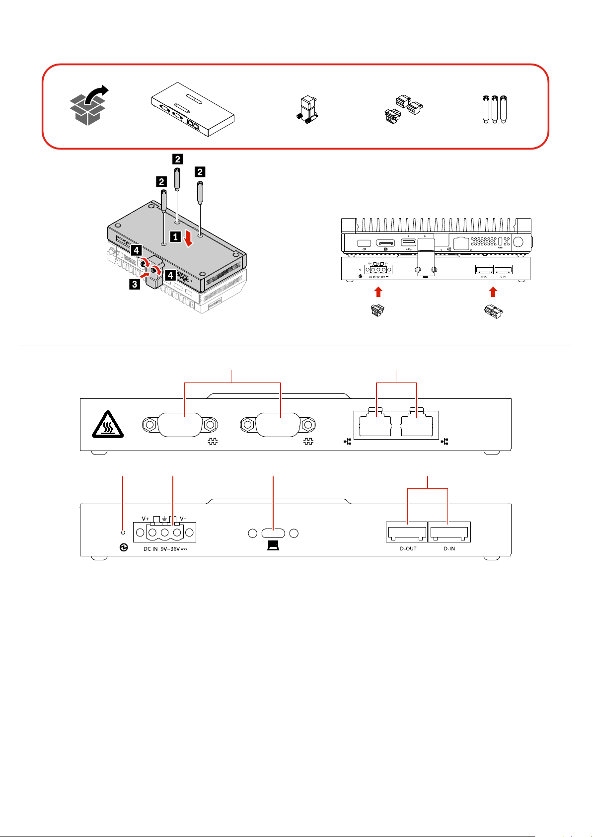
Initial Setup
21
PoE PoE
6
43
5
Overview
1. Serial connectors (2)
2. Ethernet connectors (POE)(2)
4. DC-in power connector
5. USB-C connector
3. DC-in power LED indicator
6. DI/DO connectors (2)
Page 3
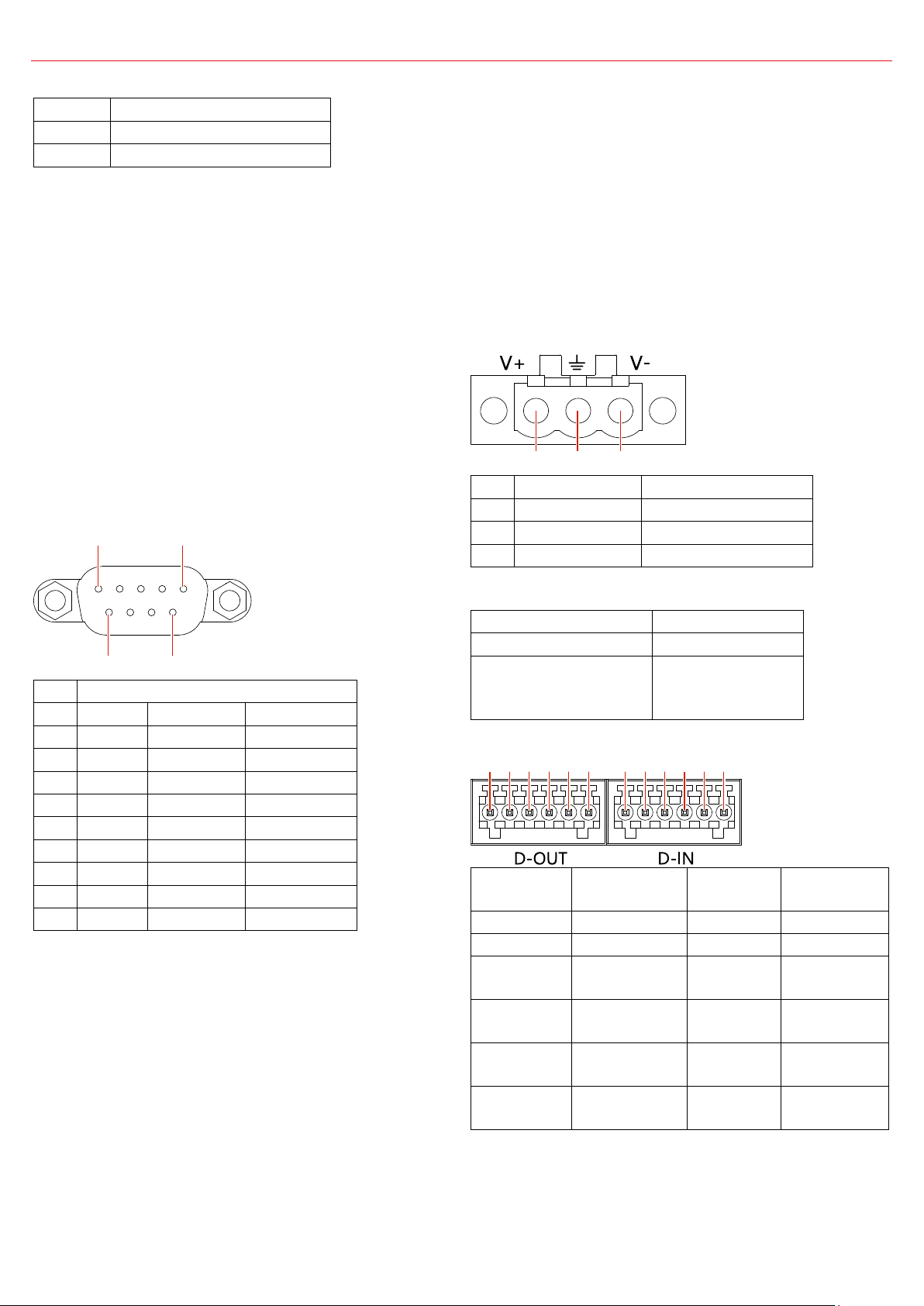
Specification
Length
178 mm (7 inches)
Width
88 mm (3.46 inches)
Height
25.6 mm (1 inch)
Pin
Signal
RS232
RS422
RS485
1
DCD#
TXD422-
485DATA-
2
RXD
TXD422+
485DATA+
3
TXD
RXD422+
N/C
4
DTR#
RXD422-
N/C
5
GND
GND
GND
6
DSR#
N/C
N/C
7
RTS#
N/C
N/C
8
CTS#
N/C
N/C
9
RI#
N/C
N/C
Pin
Signal
Cable spec
1
V+ (DC in)
24AWG-14AWG
2
GND
3
V- (DGND)
24AWG-14AWG
LED indicator color
DC power input
Green
9V ~ 36V
Red
(the box does not
work)
< 9V or >36V
D-OUT pin
number
D-OUT pin
definition
D-IN pin
number
D-IN pin
definition
1
COM
1
COM
2
GND
2
GND
3
Digital
Output
3
Digital
Input
4
Digital
Output
4
Digital
Input
5
Digital
Output
5
Digital
Input
6
Digital
Output
6
Digital
Input
1 5
6 9
1 2 3
1 2 5 63 4 1 2 5 63 4
Dimensions
Environment
Temperature
Operating: 0 ~ 50 °C (32 ~ 122 °F)
Storage: - 40 ~ 60 °C ( -40 ~ 140 °F)
Relative Humidity
Operating: 20% ~ 80% (non-condensing)
Storage: 20% ~ 90% (non-condensing)
Serial connectors
The two serial connectors support RS-232
(default), RS-422, and RS-485 standards. To use
RS-422/485 standards, change the settings with
the IoT IOBOX DT1 IO CONTROLLER application.
To download the application, go to:
https://support.lenovo.com.
They are also compatible with IEEE 802.3af or
IEEE 802.3at devices. In this case, the dc power
input to the box must be higher than 135 W.
Data transfer speed is 10/100/1000 Mbps (The
box is equipped with RTL8153B).
They support full duplex flow control (IEEE
802.3x).
Do not support Wake On LAN.
DC-in power connector
The 3-pin Phoenix dc-in power connector
accepts dc power input from 9 V (-5%) to 36 V
(+5%).
Baud rate: 50 bps ~ 115.2 Kbps
For Baud rate, Data bits, Parity, Stop bits, and
flow control detail setting, do the following:
1. Right-click the Start button to open the
Start context menu.
2. Click Device Manager, and then click
Ports(COM&LPT).
3. Double-click IoT IOBOX DT1 (COM3) or IoT
IOBOX DT1 (COM4), and then click Port
settings.
Ethernet connectors
The two Ethernet connectors are fully compliant
with IEEE 802.3, IEEE 802.3u, and IEEE 802.3ab.
The DC-in power LED indicator shows the status
of the dc power input.
DI/DO connector
-1
-2
-3
-4
-1
-2
-3
-4
Page 4
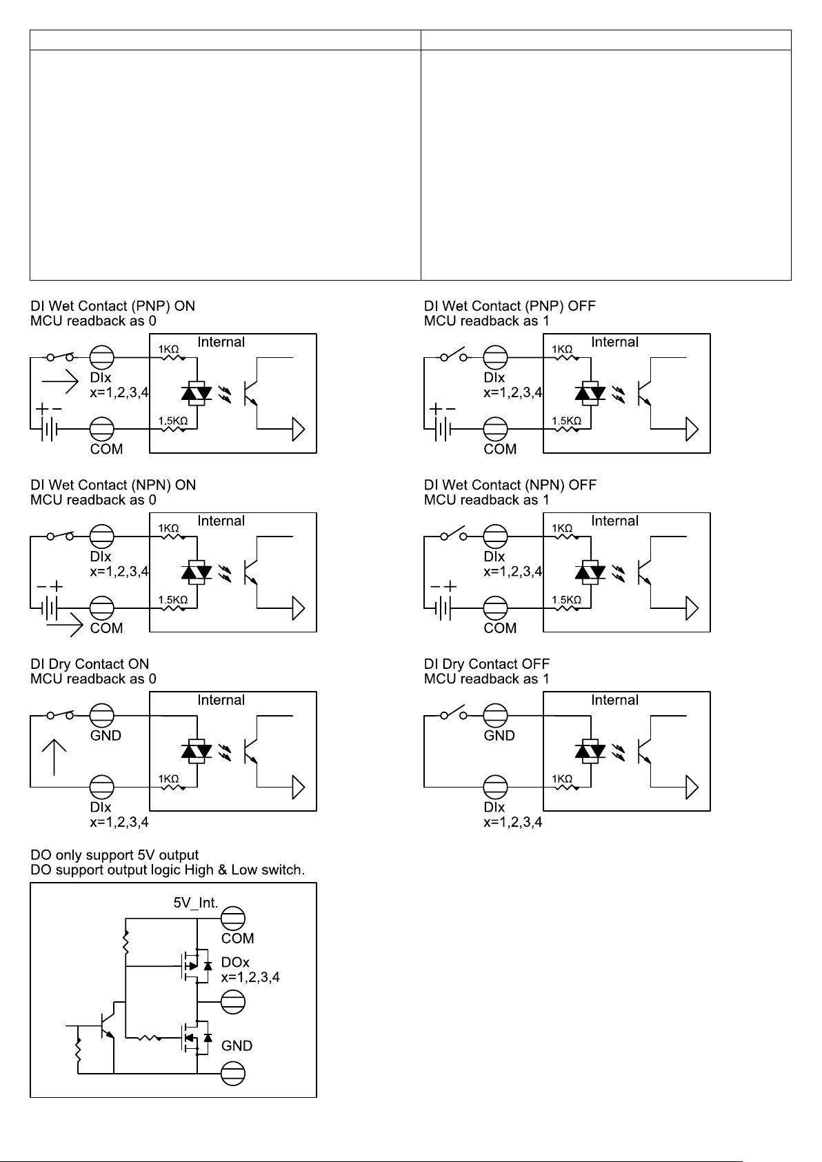
Digital Input
Digital Output
Channels: 4
Channels: 4
Note
Input type: NPN, PNP
Dry contact:
- Logic 0: Open
- Logic 1: Close to GND
Wet contact:
- Logic 0: 0 V to 0.8 V
- Logic 1: 5 V to 30 V
Input resistance: 2.5 kΩ
Isolation voltage: 1.5 kV (DC)
Overvoltage protection: 70 V (DC)
Output type: NPN
Output voltage: 5 V
Total output current: 200 mA
Isolation voltage: 1.5 kV (DC)
:
The output voltage can range from 5 V to 30 V
when an external relay module, which has
been connected to external power source
separately, is connected to the Digital Output
connector.
Page 5

A1
A2
A3
A4
A5
A6
A7
A8
A9
A10
A11
A12
GND
TX1+
TX1-
V
CC1
D+
D- V
RX2-
RX2+
GND
GND
RX1+
RX1-
V
D-
D+
CC2
V
TX2-
TX2+
GND
B12
B11
B10
B9
B8
B7
B6
B5
B4
B3
B2
B1
To connect an external device to a DI/DO adapter:
1. Use a screwdriver or anything similar with a thin tip to press down the block and hold.
2. Insert the bare stranded wires of the cable (24AWG) into the slot completely.
Notes:
The recommend length of the bare stranded wires is 4.8 - 5.5 mm (0.19 – 0.22 inches).
Tin the tips of the bare stranded wires to hold them together beforehand.
Be extremely careful when handling with a screwdriver or similar sharp tools to avoid
potential injuries to your fingers.
USB-C connector
BUS
BUS
BUS
BUS
The output voltage and current for the USB-C connector are 20 V±0.4 V/2.25 A, or 20 V±0.4 V/ 3 A
at maximum. The input voltage and current are 5 V/3 A. The connector supports USB Power
Delivery 3.0.
It transfers data at USB 3.1 Gen 1 speed, up to 5 Gbps.
Page 6

IoT IOBOX DT1 IO CONTROLLER (Windows)
IoT IOBOX DT1 IO CONTROLLER Software Introduction
IoT IOBOX DT1 IO CONTROLLER is a piece of control software specific to the industrial control
product IOBOX and controls the digital input interface, digital output interface, and COM interface.
The control functions are described as follows:
1. Digital input interface
The control software monitors the rising edge count, falling edge count, IO status, frequency,
and duty ratio of input signals of each port on the digital input interface, and controls signal
inversion by the software. Collected data is presented in the display area in real time.
2. Digital output interface
The control software configures the initial status of each port on the digital output interface (after
device access), and controls each port in real time.
3. COM interface
The control software controls two COM interfaces by enabling interface power supply, switching
the mode, configuring the transmission rate.
IoT IOBOX DT1 IO CONTROLLER UI Description
The following figure shows the main UI. In the figure, 1 is the software version number, 2 is the status
bar, 3 is the digital input control area, 4 is the digital output control area, and 5 is the COM control
area.
1. Status Bar
There are two states: "Connected" and "Disconnected". The software monitors the status of the
IOBOX DIO (Digital Input/Output) interface MCU. The status bar displays "
IOBOX is connected to the host or "
when the status bar displays "
Connected".
Disconnected" otherwise. The software is operable only
Connected" when
2. Digital Input Control Area
The Port column indicates four input ports of the digital input interface.
The left pane is the display area. When Invert, Positive, Negative, IO Status, Freq, or Duty is
configured on the right pane, the status of the configuration item is displayed on the left pane.
Specifically, "
true" indicates that a configuration item is selected, and "false" indicates that the
configuration item is not selected. After the software starts monitoring, various values of input
signals on ports are displayed on the left pane.
Page 7

Invert: to enable level inversion for input signals on ports.
Positive: rising edge count of input signals on ports.
Negative: falling edge count of input signals on ports.
Freq: frequency of input signals on ports.
Duty: duty ratio of input signals on ports.
IO Status: IO status value of input signals on ports. Only the current IO status is displayed, and
the IO status value does not reflect all IO inversion status from time t0 to t1.
3. Digital Output Control Area
The Port column indicates four output ports of the digital output interface.
The left pane is the display area. When Initial State or State (Output Configure) is configured
on the right pane, the status of the configuration item is displayed on the left pane.
indicates 1, which means high level, and
Low indicates 0, which means low level. By default,
High
Initial State and State are displayed as 1 for the four output ports.
4. COM Control Area
IoT IOBOX DT1 COM3 and IoT IOBOX DT1 COM4 are the two COM interfaces of IOBOX.
The two COM interfaces are independent of each other. Select either interface and configure the
mode, transmission rate, terminal resistor, and power supply for it.
Mode: mode of the COM interface. There are three options: RS232, RS485, and RS422. The two
COM interfaces adopt RS232 mode by default.
SLEW: transmission rate of the COM interface. The maximum transmission rate is 1 Mbps in
RS232 mode and 20 Mbps in RS485/RS422 mode. The transmission rate can be limited to 250
Kbps in SLEW regardless of the mode. Ensure that the transmit rate matches the receive rate. By
default, the transmission rate is set to 250 Kbps for the three modes.
TERM: to enable the terminal resistor. Generally, the terminal resistor does not need to be
enabled. It is enabled at the transmit and receive ends of RS485 communication only when the
distance between the two parties exceeds 300 m. By default, the terminal resistor is disabled.
COM Power: to enable power supply for the COM interface. Select "Enable" and click "Apply" to
enable power supply for the COM interface. Select "
Disable" and click "Apply" to disable power
supply for the COM interface. By default, power supply is enabled.
Page 8

IoT IOBOX DT1 IO CONTROLLER Test Guide
Before using the software, connect IOBOX to the host and connect the power supply. Power on,
access the host system, start the software, and ensure that the Status Bar displays "
that IOBOX related devices are not marked with a yellow warning mark in the host device manager.
1. Digital Input Interface Test
Step 1: Connect the DI (Digital Input) device to the DI interface of IOBOX.
Step 2: Select ports one by one in the DI control area and configure the ports in the
configuration area.
Note: "Input Mode" and "Freq Mode" are mutually exclusive for each port.
As shown in the following figure, Invert, Positive, Negative, and IO Status are enabled for ports 1
and 2, and
Freq, and Duty are enabled for ports 3 and 4.
Connected" and
Step 3: After configuration, click "Run", and then the "Run" button changes to "Stop". You can
click "
Stop" to stop monitoring.
Step 4: To reset the values (such as Positive and Negative) of signals on a certain port after
starting monitoring, select the port and click "
Reset Channel" to reset the values to 0.
2. Digital Output Interface Test
Step 1: Connect the DO (Digital Output) device to the DO interface of IOBOX.
Step 2: Adjust Initial State and State of the output port in the DO control area.
Notes:
Double-click on the left pane to set a value or select a value on the right pane.
Initial State is set to 1 for the four ports at initial software startup. After Initial State is
reset, the new value is stored in the register of IOBOX. After IOBOX is disconnected from
the host, reconnected to the host, and connected to the DO device, IOBOX initializes the
Page 9

DO device and sets Initial State as before.
State is 1 by default each time the software is started. If the current port status of the DO
device is 1, adjust it once to change the port status. If the current port status of the DO
device is 0, adjust it twice to change the port status.
Step 3: After adjustment of State, check whether the feedback of the DO device is consistent
with the adjustment.
3. COM Interface Test
Step 1: Power supply is enabled by default for the two COM interfaces of IOBOX. Therefore, you
are advised to disable power supply for the COM interface using this software (select a COM
interface, select "
Disable" in COM Power, and click "Apply"), and enable power supply after
connecting the device.
Step 2: Connect the COM device to the COM interface of IOBOX.
Step 3: After connection, set related configuration parameters in the configuration area. As
shown in the following figure, the interface is
IoT IOBOX DT1 COM3", "Mode" is set to RS232, the default value 250 Kbps is retained for
"
SLEW", and "COM Power" is set to "Enable" to enable power supply for the COM interface.
"
Then click "
Apply" for the settings to take effect.
Step 4: Check whether the COM device works correctly.
Page 10

SDK support list
SDK provides some functions to control IOBOX. Users can follow DLL API documents to implement
customized features. Items below are contained in SDK support list.
DI (Digital Input):
Changed DI mode of each port, including following modes:
Freq. Mode
Duty Mode
Level Mode
Positive/Negative Counter Start/Stop
Invert ON/OFF
DO (Digital Output):
Set high/low voltage to each output channel
Set default voltage to each output channel
COM Ports:
COM Port Enable/Disable
Changed COM port mode to RS232/RS485/RS422
Set SLEW 250kbps/1Mbps for RS232 and 250kbps/20Mbps for RS422/RS485
Set TERM Enable/Disable for RS422/RS485
Page 11

SDK Q & A
1. How to import deviceCtrl.dll and IoCtrlInterface.dll?
a. Copy deviceCtrl.dll and IoCtrlInterface.dll to Debug and Release folder
b. Right click on the project->Add->Reference, choose deviceCtrl.dll
c. Declare “using deviceCtrl” at the start of the code
2. How to initialize devCtrl object?
a. Initialize every DO port
b. Call API “SetOutPort()”
c. devCtrl.SetOutPort((byte)i, 1)
3. How to deploy a callback subroutine?
a. Call API “SetRxCallBack()”
devCtrl.SetRxCallBack(HIDOutCallBackx);
the “HIDOutCallBackx(inputStatus[] input)” is a callback routine used to receive data
inputStatus[] is a structure which contains Voltage, I/O port status, Rising count, falling count,
Frequency and Duty
namespace deviceCtrl
{
public struct inputStatus
{
public byte v;
public bool io;
public int rCount;
public int fCount;
public int Freq;
public int Duty;
}
}
b. Call API “RxThreadStart()” to start a thread then IOBOX data will be pass to the callback
“HIDOutCallBackx()”
devCtrl.RxThreadStart();
For Example:
int HIDOutCallBackx(inputStatus[] input){...}
devCtrl.SetRxCallBack(HIDOutCallBackx);
devCtrl.RxThreadStart();
4. How to monitor IOBOX connected or not?
New a thread to monitor the IOBOX status
Thread ThreadHID = new Thread(ThreadHIDHandle);
“ThreadHIDHandle()” is a subroutine used to monitor connect status of IOBOX. Then, you can
follow SDK API to call devCtrl.IsConnect() to check status
For Example:
void ThreadHIDHandle(){...}
Thread ThreadHID = new Thread(ThreadHIDHandle);
ThreadHID.Start();
5. If PC can’t show correct connect status to IOBOX, what should I do?
Page 12

a. Check IOBOX is connected to device correctly
b. Check the Driver has been installed
The device manager will show
c. Is the VID/PID information correct?
Call API “IsConnect()” to check IOBOX connect or not
devCtrl.IsConnect(0x28e9, 0x2381)
The parameter “0x28e9” and “0x2381” is the VID/PID of the IOBOX
Page 13

Note:
For support on software SDK, please send an email to our IOBOX software support team at
ioboxsdk@lenovo.com.
In your email’s subject line, please include the following:
Country – IOBOX SDK ISSUE – 8SS barcode located on host
Example: France – IOBOX SDK ISSUE – 8SSxxxxxxxx
In the email please also:
Include steps to follow to recreate the issue.
Identify any peripherals attached to the IOBOX.
Include error messages and/or description of the failure.
Our software support team will reply within 3 business days.
Fourth Edition (January 2021)
© Copyright Lenovo 2021.
LIMITED AND RESTRICTED RIGHTS NOTICE: If data or software is delivered pursuant to a General Services Administration “GSA”
contract, use, reproduction, or disclosure is subject to restrictions set forth in Contract No. GS-35F-05925.
 Loading...