

Page 1

ThinkCentre
UserGuide
MachineTypes:2756,2800,2929,2932,2934,2941,2945,2961,
2982,2988,2993,2996,3181,3183,3185,3187,3198,3202,3207,
3209,3214,3218,3224,3227,3306,3393,and3395
Page 2

Note:Beforeusingthisinformationandtheproductitsupports,besuretoreadandunderstandthe
“Importantsafetyinformation”onpagevandAppendixA“Notices”onpage131.
FourthEdition(May2012)
©CopyrightLenovo2012.
LIMITEDANDRESTRICTEDRIGHTSNOTICE:IfdataorsoftwareisdeliveredpursuantaGeneralServicesAdministration
“GSA”contract,use,reproduction,ordisclosureissubjecttorestrictionssetforthinContractNo.GS-35F-05925.
Page 3

Contents
Importantsafetyinformation......v
Serviceandupgrades.............v
Staticelectricityprevention...........v
Powercordsandpoweradapters........vi
Extensioncordsandrelateddevices.......vi
Plugsandoutlets..............vii
Externaldevices..............vii
Heatandproductventilation.........vii
Operatingenvironment...........viii
Modemsafetyinformation..........viii
Lasercompliancestatement..........ix
Powersupplystatement............ix
Cleaningandmaintenance...........ix
Chapter1.Productoverview......1
Features..................1
Specications................4
Softwareoverview..............5
SoftwareprovidedbyLenovo........5
AdobeReader..............7
Antivirussoftware.............7
Locations..................7
Locatingconnectors,controls,andindicators
onthefrontofyourcomputer........8
Locatingconnectorsontherearofyour
computer................9
Locatingcomponents..........11
Locatingpartsonthesystemboard....11
Locatinginternaldrives.........14
Machinetypeandmodellabel.......15
Chapter2.Usingyourcomputer...17
Frequentlyaskedquestions.........17
Usingthekeyboard.............17
UsingWindowsshortcutkeys.......17
UsingtheblueThinkVantagebutton....18
Usingangerprintreader........18
Usingthewheelmouse...........18
Adjustingaudio..............18
Aboutyourcomputeraudio........19
Settingthevolumefromthedesktop....19
SettingthevolumefromControlPanel...19
UsingCDsandDVDs............19
HandlingandstoringCDandDVDmedia..20
PlayingaCDorDVD..........20
RecordingaCDorDVD.........20
Chapter3.Y ouandyourcomputer..23
Accessibilityandcomfort..........23
Arrangingyourworkspace........23
Comfort...............23
Glareandlighting............24
Aircirculation.............24
Electricaloutletsandcablelengths.....24
Registeringyourcomputer..........25
Movingyourcomputertoanothercountryor
region..................25
Voltage-selectionswitch.........25
Replacementpowercords........26
Chapter4.Security..........27
Securityfeatures..............27
Attachinganintegratedcablelock.......28
Usingpasswords..............28
BIOSpasswords............28
Windowspasswords..........29
Conguringthengerprintreader.......29
Usingandunderstandingrewalls.......29
Protectingdataagainstviruses........29
Chapter5.Installingorreplacing
hardware...............31
Handlingstatic-sensitivedevices.......31
Installingorreplacinghardware........31
Installingexternaloptions........31
Openingthecomputercover.......32
Removingandreinstallingthefrontbezel..32
Accessingthesystemboardcomponentsand
drives................34
Installingorreplacingamemorymodule...35
InstallingorreplacingaPCIcard......37
Installingorreplacingthecardreader....39
InstallingorreplacingthemSATAsolidstate
drive.................44
Replacingthebattery..........51
Installingthesolidstatedrive.......52
Replacingtheharddiskdrive.......54
Replacingtheopticaldrive........56
Replacingtheheatsinkandfanassembly..59
Replacingthepowersupplyassembly...62
Replacingthemicroprocessor.......67
Replacingthecoverpresenceswitch....70
Replacingtheinternalspeaker.......72
©CopyrightLenovo2012
i
Page 4

ReplacingthefrontaudioandUSB
assembly...............74
Replacingthesystemfanassembly....76
ReplacingtheWiFiunits.........77
InstallingorremovingtherearWiFiantenna.82
InstallingorremovingthefrontWiFiantenna.84
Replacingthekeyboardormouse.....87
Completingthepartsreplacement.....87
Chapter6.Recoveryinformation...89
Creatingandusingrecoverymedia......89
Creatingrecoverymedia.........89
Usingrecoverymedia..........90
Performingbackupandrecoveryoperations...90
Performingabackupoperation......90
Performingarecoveryoperation......91
UsingtheRescueandRecoveryworkspace...91
Creatingandusingarescuemedium......92
Creatingarescuemedium........92
Usingarescuemedium.........92
Reinstallingpreinstalledapplicationsanddevice
drivers..................93
Reinstallingsoftwareprograms........94
Reinstallingdevicedrivers..........94
Solvingrecoveryproblems..........94
Chapter7.UsingtheSetupUtility
program................97
StartingtheSetupUtilityprogram.......97
Viewingandchangingsettings........97
Usingpasswords..............97
Passwordconsiderations.........98
Power-OnPassword..........98
AdministratorPassword.........98
HardDiskPassword...........98
Setting,changing,anddeletingapassword.98
Erasinglostorforgottenpasswords(clearing
CMOS)................99
Enablingordisablingadevice........99
Selectingastartupdevice..........100
Selectingatemporarystartupdevice....100
Selectingorchangingthestartupdevice
sequence...............100
EnablingErPcompliancemode........100
ICEperformancemode...........101
ICEthermalalert..............101
ExitingtheSetupUtilityprogram.......102
Chapter8.Updatingsystem
programs..............103
Usingsystemprograms...........103
Updating(ashing)theBIOSfromadisc....103
Updating(ashing)theBIOSfromyouroperating
system..................104
RecoveringfromaPOST/BIOSupdatefailure..104
Chapter9.Preventingproblems..105
Keepingyourcomputercurrent........105
Gettingthelatestdevicedriversforyour
computer...............105
Updatingyouroperatingsystem......105
UsingSystemUpdate..........106
Cleaningandmaintenance..........106
Basics................106
Cleaningyourcomputer.........107
Goodmaintenancepractices.......108
Movingyourcomputer...........108
Chapter10.Troubleshootingand
diagnostics.............109
Basictroubleshooting............109
Troubleshootingprocedure..........110
Troubleshooting..............110
Audioproblems............111
CDproblems.............112
DVDproblems.............113
Intermittentproblems..........115
Keyboard,mouse,orpointingdevice
problems...............115
Monitorproblems............116
Networkingproblems..........118
Optionproblems............121
Performanceandlockupproblems.....122
Printerproblems............123
Serialportproblems...........123
Softwareproblems...........124
USBproblems.............125
LenovoSolutionCenter...........125
Chapter11.Gettinginformation,help,
andservice.............127
Informationresources............127
LenovoThinkVantageTools........127
LenovoWelcome............127
HelpandSupport............127
SafetyandWarranty...........127
LenovoWebsite(http://www.lenovo.com)..127
LenovoSupportWebsite.........127
Helpandservice..............128
Usingthedocumentationanddiagnostic
program...............128
Callingforservice............128
Usingotherservices..........129
Purchasingadditionalservices......129
iiThinkCentreUserGuide
Page 5

AppendixA.Notices.........131
Trademarks................132
AppendixB.Regulatory
information.............133
Exportclassicationnotice..........133
Electronicemissionsnotices.........133
FederalCommunicationsCommission
DeclarationofConformity........133
Additionalregulatoryinformation.......135
AppendixC.WEEEandrecycling
information.............137
ImportantWEEEInformation.........137
Recyclinginformation............137
RecyclinginformationforBrazil........138
BatteryrecyclinginformationforT aiwan.....138
BatteryrecyclinginformationfortheEuropean
Union..................139
AppendixD.RestrictionofHazardous
SubstancesDirective(RoHS)....141
ChinaRoHS................141
TurkishRoHS...............141
UkraineRoHS...............141
IndiaRoHS................142
AppendixE.EkBilgiler.......143
AppendixF .Servisistasyonlari...145
Index.................153
©CopyrightLenovo2012
iii
Page 6

ivThinkCentreUserGuide
Page 7
Importantsafetyinformation
CAUTION:
Beforeusingthismanual,besuretoreadandunderstandalltherelatedsafetyinformationforthis
product.RefertotheinformationinthissectionandthesafetyinformationintheSafetyandWarranty
Guidethatyoureceivedwiththisproduct.Readingandunderstandingthissafetyinformationreduces
theriskofpersonalinjuryanddamagetoyourproduct.
IfyounolongerhaveacopyoftheSafetyandWarrantyGuide,youcanobtainaPortableDocumentFormat
(PDF)versionfromtheLenovo
®
SupportWebsiteathttp://www.lenovo.com/support.TheLenovoSupport
WebsitealsoprovidestheSafetyandWarrantyGuideandthisUserGuideinadditionallanguages.
Serviceandupgrades
DonotattempttoserviceaproductyourselfunlessinstructedtodosobytheCustomerSupportCenteror
yourdocumentation.OnlyuseaServiceProviderwhoisapprovedtorepairyourparticularproduct.
Note:Somecomputerpartscanbeupgradedorreplacedbythecustomer.Upgradestypicallyare
referredtoasoptions.ReplacementpartsapprovedforcustomerinstallationarereferredtoasCustomer
ReplaceableUnits,orCRUs.Lenovoprovidesdocumentationwithinstructionswhenitisappropriatefor
customerstoinstalloptionsorreplaceCRUs.Youmustcloselyfollowallinstructionswheninstallingor
replacingparts.TheOffstateofapowerindicatordoesnotnecessarilymeanthatvoltagelevelsinsidea
productarezero.Beforeyouremovethecoversfromaproductequippedwithapowercord,alwaysensure
thatthepoweristurnedoffandthattheproductisunpluggedfromanypowersource.Formoreinformation
onCRUs,refertoChapter5“Installingorreplacinghardware”onpage31.Ifyouhaveanyquestionsor
concerns,contacttheCustomerSupportCenter.
Althoughtherearenomovingpartsinyourcomputerafterthepowercordhasbeendisconnected,the
followingwarningsarerequiredforyoursafety.
CAUTION:
Hazardousmovingparts.Keepngersandotherbodypartsaway.
CAUTION:
BeforereplacinganyCRUs,turnoffthecomputerandwaitthreetoveminutestoletthecomputer
coolbeforeopeningthecover.
Staticelectricityprevention
Staticelectricity,althoughharmlesstoyou,canseriouslydamagecomputercomponentsandoptions.
Improperhandlingofstatic-sensitivepartscancausedamagetothepart.Whenyouunpackanoption
©CopyrightLenovo2012
v
Page 8

orCRU,donotopenthestatic-protectivepackagecontainingthepartuntiltheinstructionsdirectyou
toinstallit.
WhenyouhandleoptionsorCRUs,orperformanyworkinsidethecomputer,takethefollowingprecautions
toavoidstatic-electricitydamage:
•Limityourmovement.Movementcancausestaticelectricitytobuilduparoundyou.
•Alwayshandlecomponentscarefully.Handleadapters,memorymodules,andothercircuitboardsbythe
edges.Nevertouchexposedcircuitry.
•Preventothersfromtouchingcomponents.
•Whenyouinstallastatic-sensitiveoptionorCRU,touchthestatic-protectivepackagecontainingthe
parttoametalexpansion-slotcoverorotherunpaintedmetalsurfaceonthecomputerforatleasttwo
seconds.Thisreducesstaticelectricityinthepackageandyourbody.
•Whenpossible,removethestatic-sensitivepartfromthestatic-protectivepackagingandinstallthepart
withoutsettingitdown.Whenthisisnotpossible,placethestatic-protectivepackagingonasmooth,
levelsurfaceandplacethepartonit.
•Donotplacethepartonthecomputercoverorothermetalsurface.
Powercordsandpoweradapters
Useonlythepowercordsandpoweradapterssuppliedbytheproductmanufacturer.
Thepowercordsshallbesafetyapproved.ForGermany,itshallbeH05VV-F,3G,0.75mm
2
,orbetter.For
othercountries,thesuitabletypesshallbeusedaccordingly.
Neverwrapapowercordaroundapoweradapterorotherobject.Doingsocanstressthecordinwaysthat
cancausethecordtofray,crack,orcrimp.Thiscanpresentasafetyhazard.
Alwaysroutepowercordssothattheywillnotbewalkedon,trippedover,orpinchedbyobjects.
Protectpowercordandpoweradaptersfromliquids.Forinstance,donotleaveyourpowercordorpower
adapternearsinks,tubs,toilets,oronoorsthatarecleanedwithliquidcleansers.Liquidscancausea
shortcircuit,particularlyifthepowercordorpoweradapterhasbeenstressedbymisuse.Liquidsalsocan
causegradualcorrosionofpowercordterminalsand/ortheconnectorterminalsonapoweradapter,
whichcaneventuallyresultinoverheating.
Alwaysconnectpowercordsandsignalcablesinthecorrectorderandensurethatallpowercord
connectorsaresecurelyandcompletelypluggedintoreceptacles.
Donotuseanypoweradapterthatshowscorrosionattheacinputpinsorshowssignsofoverheating(such
asdeformedplastic)attheacinputoranywhereonthepoweradapter.
Donotuseanypowercordswheretheelectricalcontactsoneitherendshowsignsofcorrosionor
overheatingorwherethepowercordappearstohavebeendamagedinanyway.
Extensioncordsandrelateddevices
Ensurethatextensioncords,surgeprotectors,uninterruptiblepowersupplies,andpowerstripsthatyouuse
areratedtohandletheelectricalrequirementsoftheproduct.Neveroverloadthesedevices.Ifpowerstrips
areused,theloadshouldnotexceedthepowerstripinputrating.Consultanelectricianformoreinformation
ifyouhavequestionsaboutpowerloads,powerrequirements,andinputratings.
viThinkCentreUserGuide
Page 9

Plugsandoutlets
Ifareceptacle(poweroutlet)thatyouintendtousewithyourcomputerequipmentappearstobedamaged
orcorroded,donotusetheoutletuntilitisreplacedbyaqualiedelectrician.
Donotbendormodifytheplug.Iftheplugisdamaged,contactthemanufacturertoobtainareplacement.
Donotshareanelectricaloutletwithotherhomeorcommercialappliancesthatdrawlargeamountsof
electricity;otherwise,unstablevoltagemightdamageyourcomputer,data,orattacheddevices.
Someproductsareequippedwithathree-prongedplug.Thisplugtsonlyintoagroundedelectricaloutlet.
Thisisasafetyfeature.Donotdefeatthissafetyfeaturebytryingtoinsertitintoanon-groundedoutlet.If
youcannotinserttheplugintotheoutlet,contactanelectricianforanapprovedoutletadapterortoreplace
theoutletwithonethatenablesthissafetyfeature.Neveroverloadanelectricaloutlet.Theoverallsystem
loadshouldnotexceed80percentofthebranchcircuitrating.Consultanelectricianformoreinformation
ifyouhavequestionsaboutpowerloadsandbranchcircuitratings.
Ensurethatthepoweroutletyouareusingisproperlywired,easilyaccessible,andlocatedclosetothe
equipment.Donotfullyextendpowercordsinawaythatwillstressthecords.
Ensurethatthepoweroutletprovidesthecorrectvoltageandcurrentfortheproductyouareinstalling.
Carefullyconnectanddisconnecttheequipmentfromtheelectricaloutlet.
Externaldevices
DonotconnectordisconnectanyexternaldevicecablesotherthanUniversalSerialBus(USB)and1394
cableswhilethecomputerpowerison;otherwise,youmightdamageyourcomputer.T oavoidpossible
damagetoattacheddevices,waitatleastvesecondsafterthecomputerisshutdowntodisconnect
externaldevices.
Heatandproductventilation
Computers,poweradapters,andmanyaccessoriescangenerateheatwhenturnedonandwhenbatteries
arecharging.Alwaysfollowthesebasicprecautions:
•Donotleaveyourcomputer,poweradapter,oraccessoriesincontactwithyourlaporanypartofyour
bodyforanextendedperiodwhentheproductsarefunctioningorwhenthebatteryischarging.Y our
computer,poweradapter,andmanyaccessoriesproducesomeheatduringnormaloperation.Extended
contactwiththebodycouldcausediscomfortor,potentially,askinburn.
•Donotchargethebatteryoroperateyourcomputer,poweradapter,oraccessoriesnearammable
materialsorinexplosiveenvironments.
•Ventilationslots,fans,andheatsinksareprovidedwiththeproductforsafety,comfort,andreliable
operation.Thesefeaturesmightinadvertentlybecomeblockedbyplacingtheproductonabed,sofa,
carpet,orotherexiblesurface.Neverblock,cover,ordisablethesefeatures.
Inspectyourdesktopcomputerfordustaccumulationatleastonceeverythreemonths.Beforeinspecting
yourcomputer,turnoffthepowerandunplugthecomputer'spowercordfromtheelectricaloutlet;then
removeanydustfromventsandperforationsinthebezel.Ifyounoticeexternaldustaccumulation,then
examineandremovedustfromtheinsideofthecomputerincludingheatsinkinletns,powersupplyvents,
andfans.Alwaysturnoffandunplugthecomputerbeforeopeningthecover.Ifpossible,avoidoperating
yourcomputerwithintwofeetofhigh-trafcareas.Ifyoumustoperateyourcomputerinornearahigh-trafc
area,inspectand,ifnecessary,cleanyourcomputermorefrequently.
©CopyrightLenovo2012
vii
Page 10

Foryoursafetyandtomaintainoptimumcomputerperformance,alwaysfollowthesebasicprecautions
withyourdesktopcomputer:
•Keepthecoverclosedwheneverthecomputerispluggedin.
•Regularlyinspecttheoutsideofthecomputerfordustaccumulation.
•Removedustfromventsandanyperforationsinthebezel.Morefrequentcleaningsmightberequiredfor
computersindustyorhigh-trafcareas.
•Donotrestrictorblockanyventilationopenings.
•Donotstoreoroperateyourcomputerinsidefurniture,asthismightincreasetheriskofoverheating.
•Airowtemperaturesintothecomputershouldnotexceed35°C(95°F).
•Donotinstallairltrationdevices.Theymayinterferewithpropercooling.
Operatingenvironment
Theoptimalenvironmentinwhichtouseyourcomputeris10°C-35°C(50°F-95°F)withhumidityranging
between35%and80%.Ifyourcomputerisstoredortransportedintemperatureslessthan10°C(50°F),
allowthecoldcomputertoriseslowlytoanoptimaloperatingtemperatureof10°C-35°C(50°F-95°F)before
use.Thisprocesscouldtaketwohoursinextremeconditions.Failuretoallowyourcomputertorisetoan
optimaloperatingtemperaturebeforeusecouldresultinirreparabledamagetoyourcomputer.
Ifpossible,placeyourcomputerinawell-ventilatedanddryareawithoutdirectexposuretosunshine.
Keepelectricalappliancessuchasanelectricfan,radio,high-poweredspeakers,airconditioner,and
microwaveovenawayfromyourcomputerbecausethestrongmagneticeldsgeneratedbythese
appliancescandamagethemonitoranddataontheharddiskdrive.
Donotplaceanybeveragesontopoforbesidethecomputerorotherattacheddevices.Ifliquidisspilledon
orinthecomputeroranattacheddevice,ashortcircuitorotherdamagemightoccur.
Donoteatorsmokeoveryourkeyboard.Particlesthatfallintoyourkeyboardcancausedamage.
Modemsafetyinformation
CAUTION:
Toreducetheriskofre,useonlyNo.26AWGorlarger(forexample,No.24AWG)telecommunication
linecordlistedbyUnderwritersLaboratories(UL)orcertiedbytheCanadianStandardsAssociation
(CSA).
Toreducetheriskofre,electricalshock,orinjurywhenusingtelephoneequipment,alwaysfollowbasic
safetyprecautions,suchas:
•Neverinstalltelephonewiringduringalightningstorm.
•Neverinstalltelephonejacksinwetlocationsunlessthejackisspecicallydesignedforwetlocations.
•Nevertouchuninsulatedtelephonewiresorterminalsunlessthetelephonelinehasbeendisconnectedat
thenetworkinterface.
•Usecautionwheninstallingormodifyingtelephonelines.
•Avoidusingatelephone(otherthanacordlesstype)duringanelectricalstorm.Theremaybearemote
riskofelectricshockfromlightning.
•Donotusethetelephonetoreportagasleakinthevicinityoftheleak.
viiiThinkCentreUserGuide
Page 11
Lasercompliancestatement
CAUTION:
Whenlaserproducts(suchasCD-ROMs,DVDdrives,beropticdevices,ortransmitters)are
installed,notethefollowing:
•Donotremovethecovers.Removingthecoversofthelaserproductcouldresultinexposureto
hazardouslaserradiation.Therearenoserviceablepartsinsidethedevice.
•Useofcontrolsoradjustmentsorperformanceofproceduresotherthanthosespeciedherein
mightresultinhazardousradiationexposure.
DANGER
SomelaserproductscontainanembeddedClass3AorClass3Blaserdiode.Notethefollowing:
Laserradiationwhenopen.Donotstareintothebeam,donotviewdirectlywithoptical
instruments,andavoiddirectexposuretothebeam.
Powersupplystatement
Neverremovethecoveronapowersupplyoranypartthathasthefollowinglabelattached.
Hazardousvoltage,current,andenergylevelsarepresentinsideanycomponentthathasthislabelattached.
Therearenoserviceablepartsinsidethesecomponents.Ifyoususpectaproblemwithoneoftheseparts,
contactaservicetechnician.
Cleaningandmaintenance
Keepyourcomputerandworkspaceclean.Shutdownthecomputerandthendisconnectthepower
cordbeforecleaningthecomputer.Donotsprayanyliquiddetergentdirectlyonthecomputeroruse
anydetergentcontainingammablematerialtocleanthecomputer.Spraythedetergentonasoftcloth
andthenwipethecomputersurfaces.
©CopyrightLenovo2012
ix
Page 12

xThinkCentreUserGuide
Page 13

Chapter1.Productoverview
Thischapterprovidesinformationaboutthecomputerfeatures,specications,softwareprogramsprovided
byLenovo,andlocationsofconnectors,components,partsonthesystemboard,andinternaldrives.
Features
Thissectionprovidesinformationaboutthecomputerfeatures.Thefollowinginformationcoversavarietyof
models.Forinformationaboutyourspecicmodel,usetheSetupUtilityprogram.SeeChapter7“Using
theSetupUtilityprogram”onpage97
.
Microprocessor
Yourcomputercomeswithoneofthefollowingmicroprocessors(internalcachesizevariesbymodeltype):
•Intel
®
Core™i3microprocessor
•IntelCorei5microprocessor
•IntelCorei7microprocessor
•IntelCeleron
®
microprocessor
•IntelPentium
®
microprocessor
Memory
Yourcomputersupportsuptofourdoubledatarate3unbuffereddualinlinememorymodules(DDR3
UDIMMs).
Internaldrives
•Opticaldrive:DVD-ROMorDVD-R(optional)
•SerialAdvancedTechnologyAttachment(SATA)harddiskdrive
•SATAsolidstatedrive
Note:YourcomputersupportsSATA2.0andSATA3.0devices.Formoreinformation,see“Locatingparts
onthesystemboard”onpage11
.
Videosubsystem
•IntegratedgraphicsforaVideoGraphicsArray(VGA)connectorandaDisplayPortconnector
•PeripheralComponentInterconnect(PCI)Expressx16graphicscardslotonthesystemboardfora
discretegraphicscard
Audiosubsystem
•Integratedhigh-denition(HD)audio
•Audioline-inconnector,audioline-outconnector,andmicrophoneconnectorontherearpanel
•Microphoneconnectorandheadphoneconnectoronthefrontpanel
•Internalspeaker(installedinsomemodels)
Connectivity
•100/1000MbpsintegratedEthernetcontroller
©CopyrightLenovo2012
1
Page 14

•PCIFaxmodem(installedinsomemodels)
Systemmanagementfeatures
•Abilitytostorepower-onself-test(POST)hardwaretestresults
•DesktopManagementInterface(DMI)
DesktopManagementInterfaceprovidesacommonpathforuserstoaccessinformationaboutall
aspectsofacomputer,includingprocessortype,installationdate,attachedprintersandotherperipherals,
powersources,andmaintenancehistory.
•IntelStandardManageability
IntelStandardManageabilityishardwareandrmwaretechnologythatbuildscertainfunctionality
intocomputersinordertomakethemeasierandlessexpensiveforbusinessestomonitor,maintain,
update,upgrade,andrepair.
•IntelMatrixStorageManager
IntelMatrixStorageManagerisadevicedriverthatprovidessupportforSATARAID5arraysandSATA
RAID10arraysonspecicIntelchipsetsystemboardstoenhanceharddiskperformance.
•PrebootExecutionEnvironment(PXE)
ThePrebootExecutionEnvironmentisanenvironmenttostartcomputersusinganetworkinterface
independentofdatastoragedevices(suchastheharddiskdrive)orinstalledoperatingsystems.
•IntelligentCoolingEngine(ICE)
TheIntelligentCoolingEngineisasystemthermalmanagementsolutionthatenablesyourcomputer
torunwithbetterthermalandacousticperformance.TheICEfunctionalsomonitorsthethermal
performanceofyourcomputertoidentifythermalproblems.Formoreinformation,see“ICEperformance
mode”onpage101
and“ICEthermalalert”onpage101.
•SystemManagement(SM)BasicInput/OutputSystem(BIOS)andSMsoftware
TheSMBIOSspecicationdenesdatastructuresandaccessmethodsinaBIOSthatallowsauseror
applicationtostoreandretrieveinformationspecicaboutthecomputerinquestion.
•WakeonLAN
WakeonLANisanEthernetcomputernetworkingstandardthatallowsacomputertobeturnedon
orwokenupbyanetworkmessage.Themessageisusuallysentbyaprogramrunningonanother
computeronthesamelocalareanetwork.
•WakeonRing
WakeonRing,sometimesreferredtoasWakeonModem,isaspecicationthatallowssupported
computersanddevicestoresumefromsleeporhibernationmode.
•WindowsManagementInstrumentation(WMI)
WindowsManagementInstrumentationisasetofextensionstotheWindowsDriverModel.Itprovidesan
operatingsysteminterfacethroughwhichinstrumentedcomponentsprovideinformationandnotication.
2ThinkCentreUserGuide
Page 15

Input/Output(I/O)features
•9-pinserialport(onestandardandoneoptional)
•EightUniversalSerialBus(USB)connectors(twoonthefrontpanelandsixontherearpanel)
•OneDisplayPortconnector
•OneEthernetconnector
•OnePersonalSystem/2(PS/2)keyboardconnector(optional)
•OnePS/2mouseconnector(optional)
•OneVGAmonitorconnector
•Threeaudioconnectorsontherearpanel(audioline-inconnector,audioline-outconnector,and
microphoneconnector)
•Twoaudioconnectorsonthefrontpanel(microphoneconnectorandheadphoneconnector)
Formoreinformation,see“Locatingconnectors,controls,andindicatorsonthefrontofyourcomputer”on
page8
and“Locatingconnectorsontherearofyourcomputer”onpage9.
Expansion
•Oneharddiskdrivebay
•Oneopticaldrivebay
•OnePCIExpressx1cardslot
•OnePCIExpressx16graphicscardslot
•TwoPCIcardslots
Powersupply
Yourcomputercomeswitha240-wattautomaticvoltage-sensingpowersupply.
Securityfeatures
•ComputraceAgentsoftwareembeddedinrmware
•Coverpresenceswitch(alsocalledintrusionswitch)
•Abilitytoenableordisableadevice
•AbilitytoenableanddisableUSBconnectorsindividually
•Keyboardwithngerprintreader(shippedwithsomemodels)
•Power-onpassword(POP),administratorpassword,andharddiskdrivepasswordtodeterunauthorized
useofyourcomputer
•Startupsequencecontrol
•Startupwithoutkeyboardormouse
•Supportforanintegratedcablelock(Kensingtonlock)
•TrustedPlatformModule(TPM)
Formoreinformation,seeChapter4“Security”onpage27
.
Preinstalledsoftwareprograms
Yourcomputerispreinstalledwithsoftwareprogramstohelpyouworkmoreeasilyandsecurely.Formore
information,see“Softwareoverview”onpage5.
Preinstalledoperatingsystem
Chapter1.Productoverview3
Page 16

YourcomputerispreinstalledwiththeMicrosoft
®
Windows
®
7operatingsystem.
Operatingsystem(s),certiedortestedforcompatibility
1
(variesbymodeltype)
•Linux
®
•MicrosoftWindowsXPProfessionalSP3
Specications
Thissectionliststhephysicalspecicationsforyourcomputer.
Dimensions
Width:338mm(13.31inches)
Height:99.7mm(3.93inches)
Depth:385.4mm(15.17inches)
Weight
Maximumcongurationasshipped:7.5kg(16.53lb)
Environment
•Airtemperature:
Operating:10°Cto35°C(50°Fto95°F)
Storage:-40°Cto60°C(-40°Fto140°F)inoriginalshippingpackage
Storage:-10°Cto60°C(14°Fto140°F)withoutpackage
•Humidity:
Operating:20%to80%(non-condensing)
Storage:20%to90%(non-condensing)
•Altitude:
Operating:-50to10000ft(-15.2to3048m)
Storage:-50to35000ft(-15.2to10668m)
Electricalinput
•Inputvoltage:
–Lowrange:
Minimum:100Vac
Maximum:127Vac
Inputfrequencyrange:50to60Hz
–Highrange:
Minimum:200Vac
Maximum:240Vac
Inputfrequencyrange:50to60Hz
1.Theoperatingsystem(s)listedherearebeingcertiedortestedforcompatibilityatthetimethispublicationgoesto
press.AdditionaloperatingsystemsmightbeidentiedbyLenovoascompatiblewithyourcomputerfollowingthe
publicationofthismanual.Thislistissubjecttochange.Todetermineifanoperatingsystemhasbeencertiedor
testedforcompatibility,checktheWebsiteoftheoperatingsystemvendor.
4ThinkCentreUserGuide
Page 17
Softwareoverview
Thecomputercomeswithapreinstalledoperatingsystemandseveralsoftwareprogramsprovidedby
Lenovo.
SoftwareprovidedbyLenovo
ThefollowingsoftwareprogramsareprovidedbyLenovotohelpyouimproveproductivityandreducethe
costassociatedwithmaintainingyourcomputer.Softwareprogramsprovidedwithyourcomputermight
varydependingonyourcomputermodeltypeandpreinstalledoperatingsystem.
LenovoThinkVantageT ools
TheLenovoThinkVantage
®
Toolsprogramguidesyoutoahostofinformationsourcesandprovideseasy
accesstovarioustoolstohelpyouworkmoreeasilyandsecurely.
ToaccesstheLenovoThinkVantageToolsprogram,clickStart➙AllPrograms➙LenovoThinkVantage
Tools.
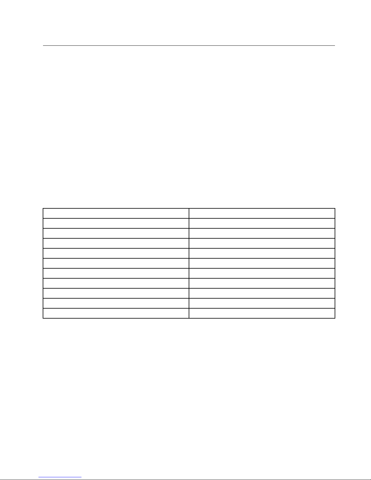
ThefollowingtableliststheprogramsthatyoucanaccessfromtheLenovoThinkVantageToolsprogram.T o
accessaprogram,double-clickthecorrespondingicon.
Table1.ProgramiconnamesinLenovoThinkVantageT ools
ProgramnameIconnameinLenovoThinkVantageTools
CreateRecoveryMedia
FactoryRecoveryDisks
FingerprintSoftware
FingerprintReader
LenovoSolutionCenterSystemHealthandDiagnostics
SimpleTapSimpleTap
ThinkVantagePasswordManagerPasswordVault
ThinkVantagePowerManager
PowerControls
ThinkVantageRescueandRecovery
®
EnhancedBackupandRestore
ThinkVantageSystemUpdate
UpdateandDrivers
CommunicationsUtilityWebConferencing
ViewManager
ScreenLayout
LenovoWelcome
TheLenovoWelcomeprogramintroducesyoutosomeinnovativebuilt-infeaturesofLenovoandguidesyou
throughafewimportantsetuptaskstohelpyoumakethemostofyourcomputer.
FingerprintSoftware
Theintegratedngerprintreaderprovidedonsomekeyboardsenablesyoutoenrollyourngerprintand
associateitwithyourpower-onpassword,harddiskpassword,andWindowspassword.Asaresult,
ngerprintauthenticationcanreplacepasswordsandenablesimpleandsecureuseraccess.Angerprint
readerkeyboardisavailablewithselectcomputersorcanbepurchasedforcomputersthatsupportthis
option.
ProductRecovery
TheProductRecoveryprogramenablesyoutorestorethecontentsoftheharddiskdrivetothefactory
defaultsettings.
Chapter1.Productoverview5
Page 18

SimpleTap
TheSimpleT approgramprovidesyouwithaquickwaytocustomizesomebasiccomputersettingssuchas
mutingthespeakers,adjustingthevolume,lockingthecomputeroperatingsystem,launchingaprogram,
openingaWebpage,openingale,andsoon.Y oualsocanusetheSimpleT approgramtoaccessthe
LenovoAppShop,fromwhichyoucandownloadvariousapplicationsandcomputersoftware.
TostarttheSimpleTapprogram,doanyofthefollowing:
•ClickStart➙AllPrograms➙SimpleTap.
•ClickStart➙AllPrograms➙LenovoThinkVantageTools,anddouble-clickSimpleT ap.
•ClicktheredSimpleTaplaunchpointonthedesktop.Theredlaunchpointisavailableonthedesktop
afteryouhavelaunchedtheSimpleTapprogramforthersttime.
•PresstheblueThinkVantagebuttonifyourkeyboardhasone.
Note:TheSimpleTapprogramisonlyavailableoncertainmodelspreinstalledwiththeWindows7operating
system.IfyourWindows7modelisnotpreinstalledwiththeSimpleTapprogram,youcandownloadit
fromhttp://www.lenovo.com/simpletap.
ThinkVantagePasswordManager
TheThinkVantagePasswordManagerprogramautomaticallycapturesandllsinauthenticationinformation
forWindowsapplicationsandWebsites.
Notes:
•TheThinkVantagePasswordManagerprogramisonlyavailableoncomputerswiththeWindows7
operatingsystemfromLenovo.
•IfthePasswordVaulticonintheLenovoThinkVantageToolsprogramisdimmed,itindicatesthatyou
needtoinstalltheThinkVantagePasswordManagerprogrammanuallybeforeenablingitsfeatures.To
installtheThinkVantagePasswordManagerprogram,dothefollowing:
1.ClickStart➙AllPrograms➙LenovoThinkVantageTools,anddouble-clickPasswordVault.
2.Followtheinstructionsonthescreen.
3.Whentheinstallationprocesscompletes,thePasswordVaulticonisactivated.
ThinkVantagePowerManager
TheThinkVantagePowerManagerprogramprovidesconvenient,exible,andcompletepowermanagement
foryourThinkCentre®computer.ByusingtheThinkVantagePowerManagerprogram,youcanadjustyour
powersettingstoachievethebestbalancebetweensystemperformanceandpowersaving.
ThinkVantageRescueandRecovery
TheThinkVantageRescueandRecoveryprogramisaonebuttonrecoveryandrestoresolutionthatincludes
asetofself-recoverytoolstohelpyoudiagnosecomputerproblems,gethelp,andrecoverfromsystem
crashes,evenifyoucannotstarttheWindowsoperatingsystem.
Note:IftheEnhancedBackupandRestoreiconintheLenovoThinkVantageToolsprogramisdimmed,it
indicatesthatyouneedtoinstalltheThinkVantageRescueandRecoveryprogrammanuallybeforeenabling
itsfeatures.T oinstalltheThinkVantageRescueandRecoveryprogram,dothefollowing:
1.ClickStart➙AllPrograms➙LenovoThinkVantageTools,anddouble-clickEnhancedBackup
andRestore.
2.Followtheinstructionsonthescreen.
3.Whentheinstallationprocesscompletes,theEnhancedBackupandRestoreiconisactivated.
6ThinkCentreUserGuide
Page 19

ThinkVantageSystemUpdate
TheThinkVantageSystemUpdateprogramhelpsyoukeepthesoftwareonyourcomputerup-to-dateby
downloadingandinstallingsoftwarepackages(ThinkVantageapplications,devicedrivers,BIOSupdates,
andotherthirdpartyapplications).
CommunicationsUtility
TheCommunicationsUtilityprogramprovidesacentrallocationforintegratedcameraandmicrophone
settings.ItcontrolsadvancedsettingsfortheintegratedmicrophoneandcameratooptimizeWeb
conferencingandVoiceoverIP(VOIP)experience.
ViewManager
TheViewManagerprogramenablesyoutoautomatewindowlocations.Itenhancesproductivityby
providingtheabilitytomovewindowstohotcornersandquicklysnapthemtoapredeterminedsize.
Itenablesyoutoworkacrossmultiplemonitors.
LenovoSolutionCenter
TheLenovoSolutionCenterprogramenablesyoutotroubleshootandresolvecomputerproblems.It
combinesdiagnostictests,systeminformationcollection,securitystatus,andsupportinformation,along
withhintsandtipsformaximumsystemperformance.See“LenovoSolutionCenter”onpage125for
detailedinformation.
AdobeReader
TheAdobeReaderprogramisatoolusedtoview,print,andsearchPDFdocuments.
Antivirussoftware
Yourcomputercomeswithantivirussoftwarethatyoucanusetodetectandeliminateviruses.Lenovo
providesafullversionofantivirussoftwareonyourharddiskdrivewithafree30-daysubscription.After30
days,youmustrenewthelicensetocontinuereceivingtheantivirusprogramupdates.
Locations
Thissectionprovidesinformationtohelpyoulocatetheconnectorsonthefrontandrearofyourcomputer,
partsonthesystemboard,andcomponentsandinternaldrivesinyourcomputer.
Chapter1.Productoverview7
Page 20
Locatingconnectors,controls,andindicatorsonthefrontofyour
computer
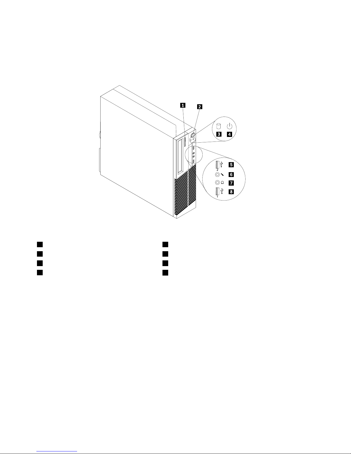
Figure1“Frontconnector,control,andindicatorlocations”onpage8showsthelocationsoftheconnectors,
controls,andindicatorsonthefrontofyourcomputer.
Figure1.Frontconnector,control,andindicatorlocations
1Opticaldriveeject/closebutton5USB2.0connector(USBport2)
2Powerswitch6Microphoneconnector
3Harddiskdriveactivityindicator7Headphoneconnector
4Powerindicator
8USB2.0connector(USBport1)
8ThinkCentreUserGuide
Page 21
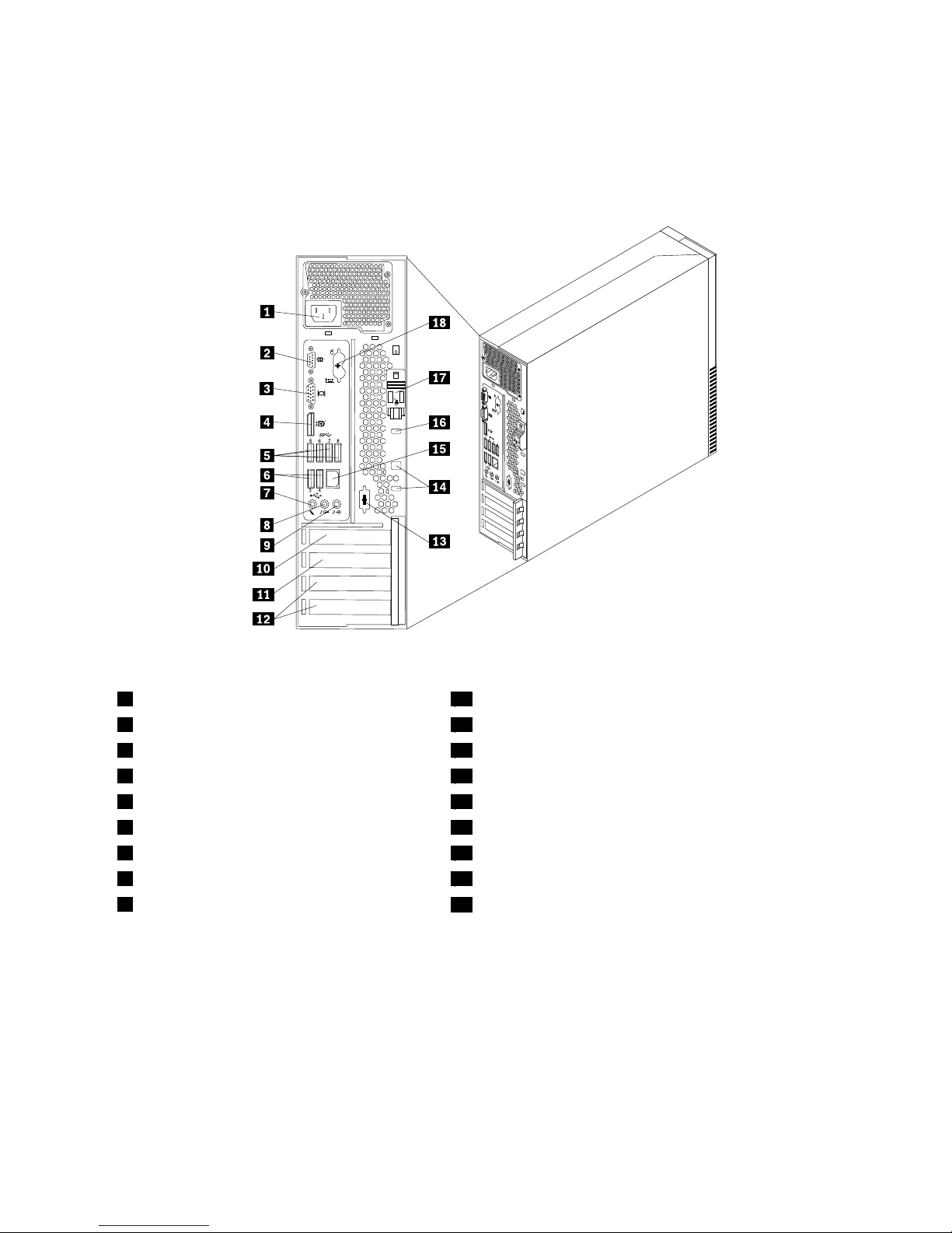
Locatingconnectorsontherearofyourcomputer
Figure2“Rearconnectorlocations”onpage9showsthelocationsoftheconnectorsontherearofyour
computer.Someconnectorsontherearofyourcomputerarecolor-codedtohelpyoudeterminewhereto
connectthecablesonyourcomputer.
Figure2.Rearconnectorlocations
1Powercordconnector
10PCIExpressx16graphicscardslot
2Serialport(Serialport1)11PCIExpressx1cardslot
3VGAmonitorconnector12PCIcardslots(2)
4DisplayPortconnector
13Optionalserialport(Serialport2)
5USB3.0connectors(USBports5to8)14Cablelockslots(2)
6USB2.0connectors(USBports3and4)
15Ethernetconnector
7Microphoneconnector
16Integratedcablelock(Kingstonlock)slot
8Audioline-outconnector
17Cover-releasebutton
9Audioline-inconnector
18PS/2keyboardandmouseconnectors(optional)
ConnectorDescription
Audioline-inconnector
Usedtoreceiveaudiosignalsfromanexternalaudiodevice,suchasastereo
system.Whenyouattachanexternalaudiodevice,acableisconnectedbetween
theaudioline-outconnectorofthedeviceandtheaudioline-inconnectorofthe
computer.
Audioline-outconnector
Usedtosendaudiosignalsfromthecomputertoexternaldevices,suchas
poweredstereospeakers(speakerswithbuilt-inampliers),headphones,
multimediakeyboards,ortheaudioline-inconnectoronastereosystemorother
externalrecordingdevice.
Chapter1.Productoverview9
Page 22

ConnectorDescription
DisplayPortconnector
Usedtoattachahigh-performancemonitor,adirect-drivemonitor,orother
devicesthatuseaDisplayPortconnector.
Ethernetconnector
UsedtoattachanEthernetcableforalocalareanetwork(LAN).
Note:TooperatethecomputerwithinFCCClassBlimits,useaCategory5
Ethernetcable.
MicrophoneconnectorUsedtoattachamicrophonetoyourcomputerwhenyouwanttorecordsoundor
ifyouusespeech-recognitionsoftware.
Serialport
Usedtoattachanexternalmodem,aserialprinter,orotherdevicesthatusea
9-pinserialport.
PS/2keyboardconnector
(optional)
UsedtoattachakeyboardthatusesaPS/2keyboardconnector.
PS/2mouseconnector(optional)Usedtoattachamouse,atrackball,orotherpointingdevicesthatuseaPS/2
mouseconnector.
USB2.0connectorUsedtoattachadevicethatrequiresaUSB2.0connector,suchasaUSB
keyboard,aUSBmouse,aUSBscanneroraUSBprinter.Ifyouhavemorethan
eightUSBdevices,youcanpurchaseaUSBhub,whichyoucanusetoconnect
additionalUSBdevices.
USB3.0connectorUsedtoattachadevicethatrequiresaUSB2.0or3.0connector,suchasaUSB
keyboard,aUSBmouse,aUSBscanneroraUSBprinter.Ifyouhavemorethan
eightUSBdevices,youcanpurchaseaUSBhub,whichyoucanusetoconnect
additionalUSBdevices.
VGAmonitorconnectorUsedtoattachaVGAmonitororotherdevicesthatuseaVGAmonitorconnector.
10ThinkCentreUserGuide
Page 23
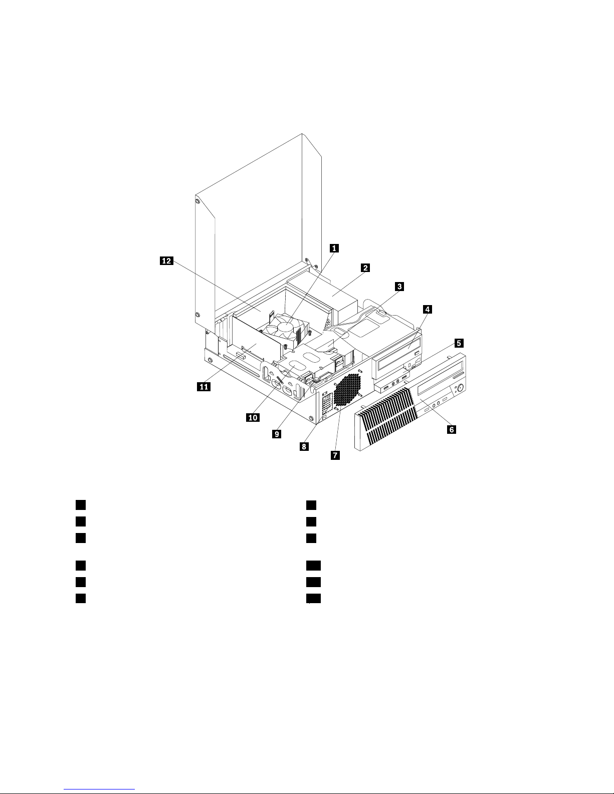
Locatingcomponents
Figure3“Componentlocations”onpage11showsthelocationsofthevariouscomponentsinyour
computer.T oopenthecomputercover,see“Openingthecomputercover”onpage32.
Figure3.Componentlocations
1Heatsinkandfanassembly
7Systemfanassembly
2Powersupplyassembly
8Internalspeaker(installedinsomemodels)
3Memorymodule
9Coverpresenceswitch(Intrusionswitch)(installedin
somemodels)
4Opticaldrive10Harddiskdrive(orsolidstatedrive)
5FrontaudioandUSBassembly11PCIcard(installedinsomemodels)
6Frontbezel
12Heatsinkfanduct
Locatingpartsonthesystemboard
Note:Yourcomputercomeswithoneofthefollowingsystemboards.
Chapter1.Productoverview11
Page 24
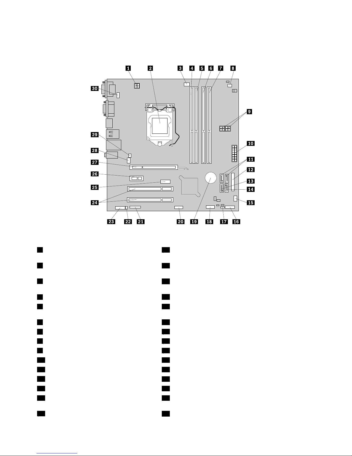
Figure4“Systemboardpartlocations”onpage12showsthelocationsofthepartsononetypeofsystem
board.
Figure4.Systemboardpartlocations
14-pinmicroprocessorpowerconnector
16Frontpanelconnector(forconnectingLEDindicatorsand
powerswitch)
2Microprocessor
17ClearCMOS(ComplementaryMetalOxideSemiconductor)
/Recoveryjumper
3Microprocessorfanconnector
18FrontUSBconnector1(forconnectingUSBports1and2
onthefrontbezel)
4Memoryslot1(DIMM1)
19Battery
5Memoryslot2(DIMM2)20FrontUSBconnector2(forconnectingadditionalUSB
devices)
6Memoryslot3(DIMM3)21Serial(COM2)connector
7Memoryslot4(DIMM4)
22Internalspeakerconnector
8Thermalsensorconnector23Frontaudioconnector
94-pinSATApowerconnectors(2)24PCIcardslots(2)
1014-pinpowerconnector25DisplayPortconnector
11SA TAconnectors1and2(SATA3.0connectors)26PCIExpressx1cardslot
12Parallelconnector
27PCIExpressx16graphicscardslot
13eSATAconnector28Systemfanconnector
14SATAconnector3(SATA2.0connector)29Coverpresenceswitchconnector(Intrusionswitch
connector)
15Powerfanconnector
30PS/2keyboardandmouseconnector
12ThinkCentreUserGuide
Page 25
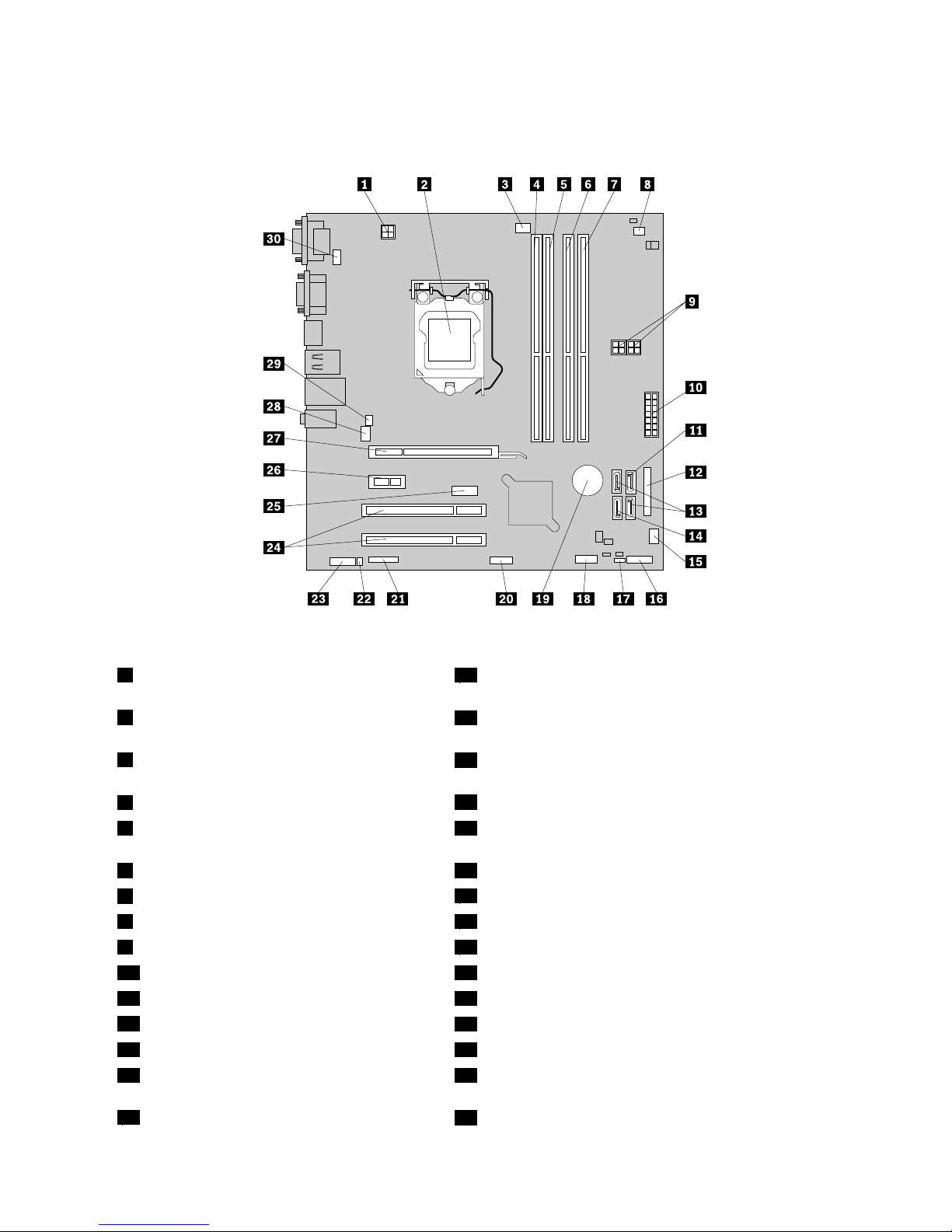
Figure5“Systemboardpartlocations”onpage13showsthelocationsofthepartsontheothertype
ofsystemboard.
Figure5.Systemboardpartlocations
14-pinmicroprocessorpowerconnector
16Frontpanelconnector(forconnectingLEDindicatorsand
powerswitch)
2Microprocessor
17ClearCMOS(ComplementaryMetalOxideSemiconductor)
/Recoveryjumper
3Microprocessorfanconnector
18FrontUSBconnector1(forconnectingUSBports1and2
onthefrontbezel)
4Memoryslot1(DIMM1)
19Battery
5Memoryslot2(DIMM2)20FrontUSBconnector2(forconnectingadditionalUSB
devices)
6Memoryslot3(DIMM3)21Serial(COM2)connector
7Memoryslot4(DIMM4)
22Internalspeakerconnector
8Thermalsensorconnector23Frontaudioconnector
94-pinSATApowerconnectors(2)24PCIcardslots(2)
1014-pinpowerconnector25DisplayPortconnector
11SATAconnector1(SATA3.0connector)26PCIExpressx1cardslot
12Parallelconnector
27PCIExpressx16graphicscardslot
13SA TAconnectors2and3(SATA2.0connectors)28Systemfanconnector
14eSATAconnector29Coverpresenceswitchconnector(Intrusionswitch
connector)
15Powerfanconnector
30PS/2keyboardandmouseconnector
Chapter1.Productoverview13
Page 26
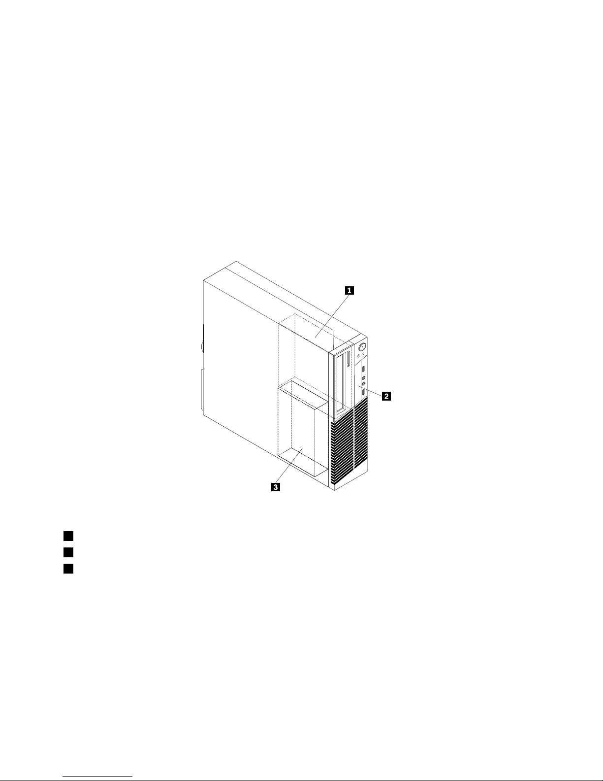
Locatinginternaldrives
Internaldrivesaredevicesthatyourcomputerusestoreadandstoredata.Youcanadddrivestoyour
computertoincreasestoragecapacityandenableyourcomputertoreadothertypesofmedia.Internal
drivesareinstalledinbays.Inthismanual,thebaysarereferredtoasbay1,bay2,andsoon.Your
computercomeswiththefollowingfactory-installeddrives:
•Anopticaldriveinbay1
•A3.5-inchharddiskdriveora2.5-inchsolidstatedriveinbay3
Wheninstallingorreplacinganinternaldrive,itisimportanttonotethetypeandsizeofthedrivethatyou
caninstallorreplaceineachbayandcorrectlyconnectthecablestothedriveinstalled.Refertothe
appropriatesectioninChapter5“Installingorreplacinghardware”onpage31
forinstructionsonhowto
installorreplaceinternaldrivesforyourcomputer.
Figure6“Drivebaylocations”onpage14
showsthelocationsofthedrivebays.
Figure6.Drivebaylocations
1Bay1-Opticaldrivebay(withanopticaldriveinstalled)
2Bay2-CardreaderdrivebayormSATAsolidstatedrivebay
3Bay3-SAT Aharddiskdrivebay(witha3.5-inchharddiskdriveora2.5-inchsolidstatedriveinstalled)
14ThinkCentreUserGuide
Page 27
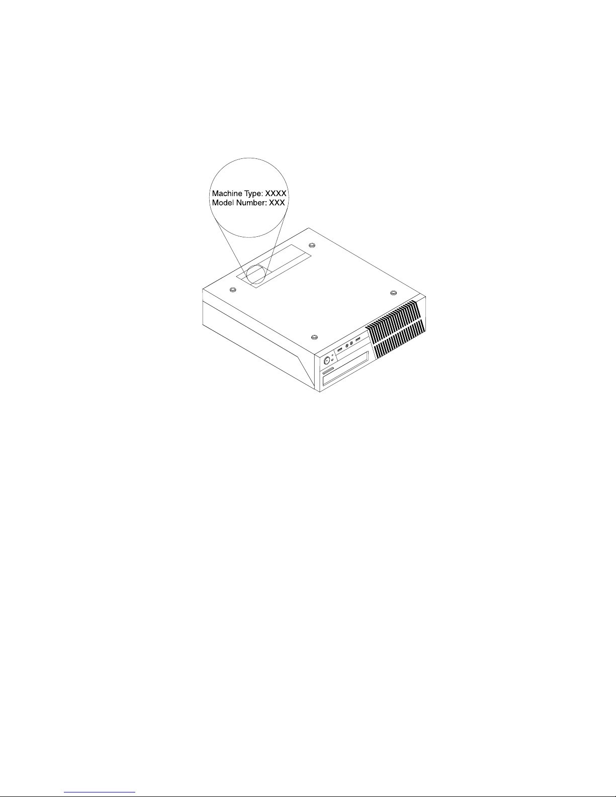
Machinetypeandmodellabel
Themachinetypeandmodellabelidentiesyourcomputer.WhenyoucontactLenovoforhelp,themachine
typeandmodelinformationhelpssupporttechnicianstoidentifyyourcomputerandprovidefasterservice.
Thefollowingisasampleofthemachinetypeandmodellabel.
Figure7.Machinetypeandmodellabel
Chapter1.Productoverview15
Page 28

16ThinkCentreUserGuide
Page 29

Chapter2.Usingyourcomputer
Thischapterprovidesinformationonusingsomeofthecomputercomponents.
Frequentlyaskedquestions
Thefollowingareafewtipsthatwillhelpyouoptimizetheuseofyourcomputer.
CanIgetmyuserguideinanotherlanguage?
TheuserguideisavailableinvariouslanguagesontheLenovoSupportWebsiteat:
http://www.lenovo.com/ThinkCentreUserGuides
Wherearemyrecoverydiscs?
Lenovoprovidesaprogramthatenablesyoutocreaterecoverydiscs.Fordetailsaboutcreatingrecovery
discs,see“Creatingrecoverymedia”onpage89.
Additionally,incaseofaharddiskfailure,youcanorderProductRecoverydiscsfromtheLenovoCustomer
SupportCenter.ForinformationaboutcontactingtheCustomerSupportCenter,seeChapter11“Getting
information,help,andservice”onpage127.BeforeusingtheProductRecoverydiscs,refertothe
documentationthatcomeswiththediscs.
Attention:AProductRecoverydiscpackagemightcontainmultiplediscs.Ensurethatyouhaveallofthe
discsreadybeforestartingtherecoveryprocess.Duringtherecoveryprocess,youmightbeprompted
tochangediscs.
WherecanIndhelpabouttheWindowsoperatingsystem?
TheWindowsHelpandSupportinformationsystemprovidesyoudetailedinformationaboutusingthe
Windowsoperatingsystemtohelpyougetthemostofyourcomputer.ToaccesstheWindowsHelpand
Supportinformationsystem,clickStart➙HelpandSupport.
Usingthekeyboard
Dependingonyourmodel,yourcomputercomeswitheitherastandardkeyboardorangerprintreader
keyboard.TheMicrosoftWindowsshortcutkeysareprovidedonbothkeyboardtypes.
Thissectionprovidesinformationaboutthefollowingtopics:
•“UsingWindowsshortcutkeys”onpage17
•“UsingtheblueThinkVantagebutton”onpage18
•“Usingangerprintreader”onpage18
UsingWindowsshortcutkeys
Boththestandardkeyboardandthengerprintreaderkeyboardprovidethreekeysyoucanusewithyour
MicrosoftWindowsoperatingsystem.
•ThetwoStartmenukeysarelocatedbesidetheAltkeyoneithersideofthespacebar.Theyfeaturethe
Windowslogo.Whenyoupresseither,theWindowsStartmenuopens.ThestyleoftheWindowslogo
variesdependingonthekeyboardtype.
•Thecontext-menukeyislocatednexttotheCtrlkeyontherightsideoftheSpacebar.Pressingthe
context-menukeyopensthecontextmenufortheactiveprogram,icon,orobject.
©CopyrightLenovo2012
17
Page 30
Note:YoucanusethemouseortheUpandDownarrowkeystohighlightmenuselections.Youcanclose
theStartmenuorthecontextmenubyclickingthemouseorpressingEsc.
UsingtheblueThinkVantagebutton
SomekeyboardshaveablueThinkVantagebuttonthatyoucanusetoopenacomprehensiveon-board
helpandinformationcenterfromLenovo.
OntheWindows7operatingsystem,pressingtheblueThinkVantagebuttonopenstheSimpleT approgram.
See“SimpleTap”onpage6formoreinformation.
Usingangerprintreader
Somecomputersmightcomewithakeyboardthathasangerprintreader.Formoreinformationaboutthe
ngerprintreader,see“FingerprintSoftware”onpage5
.
ToopentheThinkVantageFingerprintSoftwareprogramandusethengerprintreader,clickStart➙All
Programs➙LenovoThinkVantageTools➙FingerprintReader.
Followtheinstructionsonthescreen.Foradditionalinformation,refertotheThinkVantageFingerprint
Softwarehelpsystem.
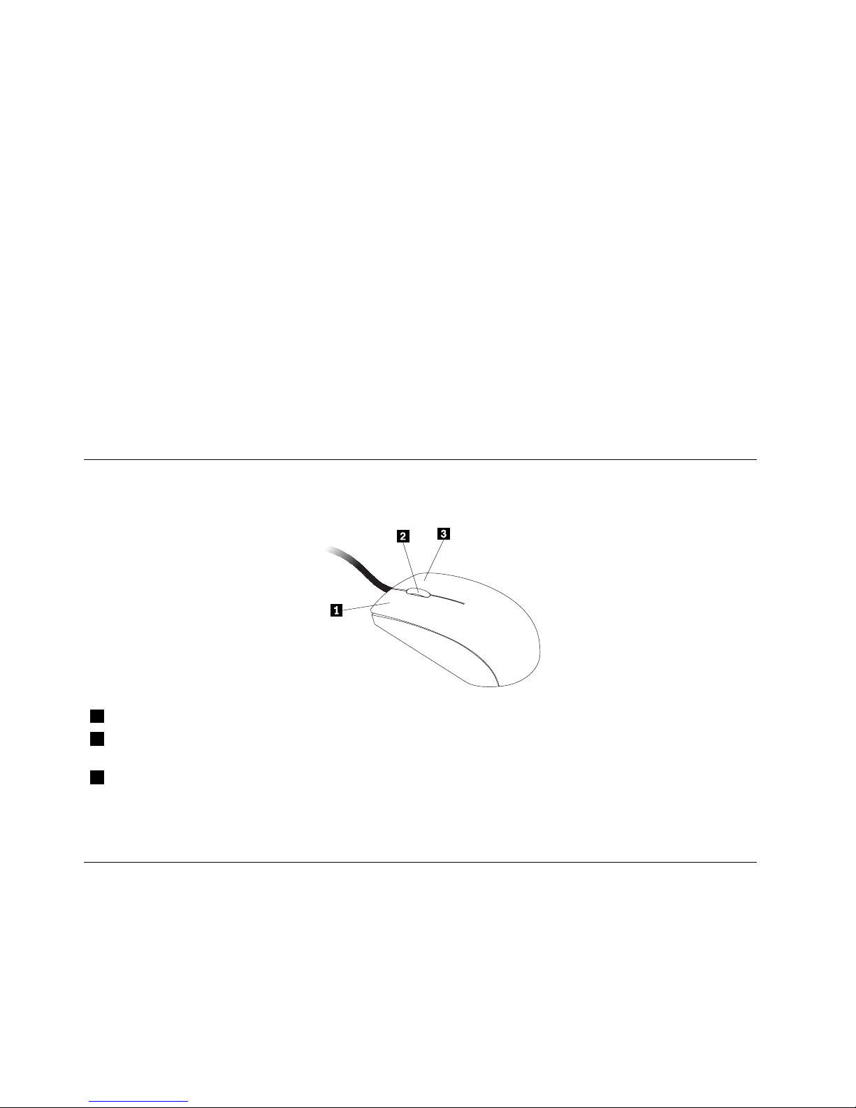
Usingthewheelmouse
Thewheelmousehasthefollowingcontrols:
1PrimarymousebuttonUsethisbuttontoselectorstartaprogramormenuitem.
2Wheel
Usethewheeltocontrolthescrollingactionofthemouse.Thedirectioninwhichyou
rotatethewheelcontrolsthedirectionofthescrollingaction.
3Secondarymousebutton
Usethisbuttontodisplayamenufortheactiveprogram,icon,orobject.
Youcanswitchthefunctionoftheprimaryandsecondarymousebuttonsandchangeotherdefaultbehavior
throughthemousepropertiesfunctionintheWindowsControlPanel.
Adjustingaudio
Soundisanimportantpartofthecomputerexperience.Yourcomputerhasadigitalaudiocontrollerbuilt
intothesystemboard.Somemodelsalsohaveahigh-performanceaudioadapterinstalledinoneofthePCI
cardslots.
18ThinkCentreUserGuide
Page 31

Aboutyourcomputeraudio
Ifafactory-installed,high-performanceaudioadapterisinstalledinyourcomputer,thesystem-board
audioconnectorsontherearofthecomputeraretypicallydisabled;usetheconnectorsprovidedonthe
audioadapter.
Eachaudiosolutionprovidesatleastthreeaudioconnectors:audioline-inconnector,audioline-out
connector,andMicrophoneconnector.Onsomemodels,afourthconnectorisprovidedfortheattachment
ofunpoweredstereospeakers(speakersthatdonotrequireanacpowersource).Theaudioadapter
providesyouwiththeabilitytorecordandplaybacksoundandmusic,aswellastoenjoysoundwith
multimediaapplicationsandworkwithspeech-recognitionsoftware.
Optionally,youcanconnectasetofpoweredstereospeakerstotheaudioline-outconnectortoenjoy
bettersoundwithmultimediaapplications.
Settingthevolumefromthedesktop
Thedesktopvolumecontrolisaccessiblethroughthevolumeiconinthetaskbar,whichislocatedatthe
bottom-rightcorneroftheWindowsdesktop.Clickthevolumeiconandmovethesliderupordownto
controlthevolume,orclicktheMuteicontoturntheaudiooff.Ifthevolumeiconisnotinthetaskbar,see
“Addingthevolumeicontothetaskbar”onpage19
.
Addingthevolumeicontothetaskbar
ToaddthevolumeicontothetaskbarontheWindows7operatingsystem,dothefollowing:
1.FromtheWindowsdesktop,clickStart➙ControlPanel➙AppearanceandPersonalization.
2.IntheT askbarandStartMenutopic,clickCustomizeiconsonthetaskbar.
3.ClickTurnsystemiconsonoroffandchangethevolumebehaviorsfromOfftoOn.
4.ClickOKtosavethenewsettings.
SettingthevolumefromControlPanel
YoucansetthecomputervolumefromControlPanel.TosetthecomputervolumefromControlPanel,
dothefollowing:
1.FromtheWindowsdesktop,clickStart➙ControlPanel➙HardwareandSound.
2.IntheSoundtopic,clickAdjustsystemvolume.
3.Movetheslidersupordowntoraiseorlowerthevolumeofyourcomputer.
UsingCDsandDVDs
YourcomputermighthaveaDVDROMdriveorrecordableDVDdriveinstalled.DVDdrivesuse
industry-standard,12cm(4.75-inch)CDmediaorDVDmedia.IfyourcomputercomeswithaDVDdrive,
thedrivecanreadDVD-ROMdiscs,DVD-Rdiscs,DVD-RAMdiscs,DVD-RWdiscs,andalltypesofCDs,
suchasCD-ROMdiscs,CD-RWdiscs,CD-Rdiscs,andaudioCDs.IfyouhavearecordableDVDdrive,
itcanalsorecordonDVD-Rdiscs,DVD-RWdiscs,typeIIDVD-RAMdiscs,CD-RWstandardandhigh
speeddiscs,andCD-Rdiscs.
FollowtheseguidelineswhenusingtheDVDdrive:
•Donotplacethecomputerinalocationwherethedriveisexposedtothefollowing:
–Hightemperature
–Highhumidity
–Excessivedust
Chapter2.Usingyourcomputer19
Page 32

–Excessivevibrationorsuddenshock
–Aninclinedsurface
–Directsunlight
•DonotinsertanyobjectotherthanaCDorDVDintothedrive.
•Beforemovingthecomputer,removetheCDorDVDfromthedrive.
HandlingandstoringCDandDVDmedia
CDandDVDmediaaredurableandreliable,buttheydorequiresomecareandspecialhandling.When
handlingandstoringaCDorDVD,followtheseguidelines:
•Holdthediscbyitsedges.Donottouchthesurfaceofthesidethatisnotlabeled.
•Toremovedustorngerprints,wipethediscwithaclean,softclothfromthecentertotheoutside.Wiping
thediscinacirculardirectionmightcauselossofdata.
•Donotwriteorstickpaperonthedisc.
•Donotscratchormarkthedisc.
•Donotplaceorstorethediscindirectsunlight.
•Donotusebenzene,thinners,orothercleanerstocleanthedisc.
•Donotdroporbendthedisc.
•Donotinsertdamageddiscsintothedrive.Warped,scratched,ordirtydiscscandamagethedrive.
PlayingaCDorDVD
IfyourcomputercomeswithaDVDdrive,youcanlistentoaudioCDsorwatchDVDmovies.T oplaya
CDorDVD,dothefollowing:
1.PresstheEject/LoadbuttonontheDVDdrivetoopenthetray.
2.Withthetrayfullyextended,inserttheCDorDVDintothetray.SomeDVDdriveshaveasnaphubinthe
centerofthetray.Ifyourdrivehasasnaphub,supportthetraywithonehandandthenpushonthe
centeroftheCDorDVDuntilitsnapsintoplace.
3.PresstheEject/Loadbuttonagainorgentlypushthetrayforwardtoclosethetray.TheCDorDVD
playerprogramstartsautomatically.Foradditionalinformation,refertotheCDorDVDplayerprogram
helpsystem.
ToremoveaCDorDVDfromtheDVDdrive,dothefollowing:
1.Withthecomputeron,presstheEject/Loadbutton.Whenthetrayslidesoutautomatically,carefully
removethedisc.
2.ClosethetraybypressingtheEject/Loadbuttonorbygentlypushingthetrayforward.
Note:IfthetraydoesnotslideoutofthedrivewhenyoupresstheEject/Loadbutton,insertastraightened
paperclipintotheemergency-ejectholelocatedonthefrontoftheDVDdrive.Ensurethatthedriveis
poweredoffwhenusingtheemergencyeject.UsetheEject/Loadbuttoninsteadoftheemergencyeject
exceptinanemergency.
RecordingaCDorDVD
IfyourcomputercomeswitharecordableDVDdrive,youcanusethedrivetorecordCDsorDVDs.To
recordaCDorDVD,dothefollowing:
1.ClickStart➙AllPrograms➙CorelDVDMovieFactoryLenovoEdition.
2.Followtheinstructionsonthescreen.
20ThinkCentreUserGuide
Page 33

FordetailedinformationaboutusingtheCorelDVDMovieFactoryprogram,seethehelpsystemforthe
program.
YoucanalsouseWindowsMediaPlayertorecordCDsanddataDVDs.Formoreinformation,see“Helpand
Support”onpage127.
Chapter2.Usingyourcomputer21
Page 34

22ThinkCentreUserGuide
Page 35

Chapter3.Youandyourcomputer
Thischapterprovidesinformationaboutaccessibility,comfort,andrelocatingyourcomputertoother
countriesorregions.
Accessibilityandcomfort
Goodergonomicpracticeisimportanttogetthemostfromyourpersonalcomputerandtoavoiddiscomfort.
Arrangeyourworkplaceandtheequipmentyouusetosuityourindividualneedsandthekindofwork
thatyouperform.Inaddition,usehealthyworkhabitstomaximizeyourperformanceandcomfortwhile
usingyourcomputer.
Thefollowingtopicsprovideinformationaboutarrangingyourworkarea,settingupyourcomputer
equipment,andestablishinghealthyworkhabits:
Lenovoiscommittedtoprovidingpeoplewithdisabilitiesgreateraccesstoinformationandtechnology.
Asaresult,thefollowinginformationprovideswaystohelpusersthathavehearing,vision,andmobility
limitationsgetthemostoutoftheircomputerexperience.
Assistivetechnologiesenableuserstoaccessinformationinthemostappropriateway.Someofthese
technologiesarealreadyprovidedinyouroperatingsystem,otherscanbepurchasedthroughvendors,or
accessedthroughtheWorldWideWeb:
http://www.lenovo.com/healthycomputing
Arrangingyourworkspace
Togetthemostfromyourcomputer,arrangeboththeequipmentyouuseandyourworkareatosuityour
needsandthekindofworkyoudo.Yourcomfortisofforemostimportance,butlightsources,aircirculation,
andthelocationofelectricaloutletscanalsoaffectthewayyouarrangeyourworkspace.
Comfort
Althoughnosingleworkingpositionisidealforeveryone,hereareafewguidelinestohelpyounda
positionthatsuitsyoubest.
Sittinginthesamepositionforalongtimecancausefatigue.Thebackrestandseatofyourchairshould
adjustindependentlyandprovidegoodsupport.Theseatshouldhaveacurvedfronttorelievepressureon
thethighs.Adjusttheseatsothatyourthighsareparalleltotheoorandyourfeetareeitheratonthe
oororonafootrest.
Whenusingthekeyboard,keepyourforearmsparalleltotheoorandyourwristsinacomfortableposition.
Usealighttouchonthekeyboardandyourhandsandngersrelaxed.Changetheangleofthekeyboard
formaximumcomfortbyadjustingthepositionofthekeyboardfeet.
©CopyrightLenovo2012
23
Page 36

Adjustthemonitorsothetopofthescreenisat,orslightlybelow,eyelevel.Placethemonitorata
comfortableviewingdistance,usually51to61cm(20to24inches),andpositionitsoyoucanviewit
withouthavingtotwistyourbody.Also,positionotherequipmentyouuseregularly,suchasthetelephoneor
amouse,withineasyreach.
Glareandlighting
Positionthemonitortominimizeglareandreectionsfromoverheadlights,windows,andotherlightsources.
Reectedlightfromshinysurfacescancauseannoyingreectionsonyourmonitorscreen.Placethe
monitoratrightanglestowindowsandotherlightsources,whenpossible.Reduceoverheadlighting,if
necessary,byturningofflightsorusinglowerwattagebulbs.Ifyouinstallthemonitornearawindow,use
curtainsorblindstoblockthesunlight.Youcanadjustthebrightnessandcontrastcontrolsonthemonitor
astheroomlightingchangesthroughouttheday.
Whereitisimpossibletoavoidreectionsortoadjustthelighting,anantiglarelterplacedoverthescreen
mightbehelpful.However,theseltersmightaffecttheclarityoftheimageonthescreen;trythemonlyafter
youhaveexhaustedothermethodsofreducingglare.
Dustbuildupcompoundsproblemsassociatedwithglare.Remembertocleanyourmonitorscreen
periodicallyusingasoftclothasdirectedinyourmonitordocumentation.
Aircirculation
Yourcomputerandmonitorproduceheat.Thecomputerhasafanthatpullsinfreshairandforcesouthot
air.Themonitorletshotairescapethroughvents.Blockingtheairventscancauseoverheating,whichmight
resultinamalfunctionordamage.Placethecomputerandmonitorsothatnothingblockstheairvents;
usually,51mm(2inches)ofairspaceissufcient.Also,ensurethattheventedairisnotblowingonpeople.
Electricaloutletsandcablelengths
Thelocationofelectricaloutlets,thelengthofpowercordsandcablesthatconnecttothemonitor,printer,
andotherdevicesmightdeterminethenalplacementofyourcomputer.
Whenarrangingyourworkspace:
•Avoidtheuseofextensioncords.Whenpossible,plugthecomputerpowercorddirectlyintoanelectrical
outlet.
•Keeppowercordsandcablesneatlyroutedawayfromwalkwaysandotherareaswheretheymight
getkickedaccidentally.
Formoreinformationaboutpowercords,see“Powercordsandpoweradapters”onpagevi
.
24ThinkCentreUserGuide
Page 37

Registeringyourcomputer
Whenyouregisteryourcomputer,informationisenteredintoadatabase,whichenablesLenovotocontact
youincaseofarecallorothersevereproblem.AfteryouregisteryourcomputerwithLenovo,youwillreceive
quickerservicewhenyoucallLenovoforhelp.Inaddition,somelocationsofferextendedprivilegesand
servicestoregisteredusers.
ToregisteryourcomputerwithLenovo,dooneofthefollowing:
•ConnectyourcomputertotheInternetandregisteryourcomputerthroughthepreinstalledLenovo
ProductRegistrationprogram.Theprogramlaunchesautomaticallyafteryouhaveusedyourcomputer
foratime.Followtheinstructionsonthescreentoregisteryourcomputer.
•Gotohttp://www.lenovo.com/registerandfollowtheinstructionsonthescreentoregisteryourcomputer.
Movingyourcomputertoanothercountryorregion
Whenyoumoveyourcomputertoanothercountryorregion,youmusttakelocalelectricalstandardsinto
consideration.Thissectionprovidesinformationonthefollowing:
•“Voltage-selectionswitch”onpage25
•“Replacementpowercords”onpage26
Voltage-selectionswitch
Somecomputersareequippedwithavoltage-selectionswitchlocatednearthepower-cordconnection
pointonthecomputerandsomecomputersdonothaveavoltage-selectionswitch.Beforeyouinstall
yourcomputerorrelocateyourcomputertoanothercountryorregion,youmustbecertainthatyouhave
matchedyourcomputertothevoltageavailableatyourelectricaloutlet.
CAUTION:
Youmustknowthevoltageoftheelectricalconnection(outlet)whereyourcomputerwillbe
connected.Ifyoudonotknowthevoltage,contactyourlocalelectriccompanyorrefertoofcial
Websitesorotherliteraturefortravelerstothecountryorregionwhereyouarelocated.
Ifyourcomputerhasavoltage-selectionswitch,youmustsettheswitchtomatchthevoltageavailableat
yourelectricaloutlet.Settingthevoltage-selectionswitchincorrectlywillcausethecomputertomalfunction
andmightcausepermanentdamagetothecomputer.Donotconnectthecomputertoanelectrical
outletuntilyouhaveveriedthatthevoltage-selectionswitchsettingmatchesthevoltageavailableatthe
electricaloutlets.
Ifyourcomputerdoesnothaveavoltage-selectionswitch,inspectthevoltage-ratinglabelonthebottomof
thecomputerandnotethefollowing:
•Ifthevoltage-ratinglabelshowsarangeofeither“100-127V”or“200-240V,”youmustensurethatthe
voltageprovidedattheelectricaloutletmatchesthevoltageratingonthecomputerlabel.Ifitdoes
notmatch,donotattempttoconnectthecomputertotheelectricaloutlet,unlessanexternaldevice
suchasavoltage-convertingtransformerisused.
•Ifthevoltage-ratinglabelshowsadualrangeof“100-127V”and“200-240V,”thissigniesthatthe
computerissuitableforworldwideoperationandthecomputerwillautomaticallyadjusttothevoltageat
theelectricaloutletregardlessofthecountryorregionwherethecomputerisbeingconnected.
Chapter3.Y ouandyourcomputer25
Page 38

Replacementpowercords
Ifyourelocateyourcomputertoacountryorregionthatusesanelectricaloutletstyledifferentfromthe
typeyouarecurrentlyusing,youwillhavetopurchaseeitherelectricalplugadaptersornewpowercords.
YoucanorderpowercordsdirectlyfromLenovo.
Forpowercordinformationandpartnumbers,goto:
http://www.lenovo.com/powercordnotice
26ThinkCentreUserGuide
Page 39

Chapter4.Security
Thischapterprovidesinformationabouthowtoprotectyourcomputerfromtheftandunauthorizeduse.
Securityfeatures
Thefollowingsecurityfeaturesareavailableonyourcomputer:
•ComputraceAgentsoftwareembeddedinrmware
TheComputraceAgentsoftwareisanITassetmanagementandcomputertheftrecoverysolution.
Thesoftwaredetectsifchangeshavebeenmadeonthecomputer,suchashardware,software,or
thecomputercall-inlocation.
Note:YoumighthavetopurchaseasubscriptiontoactivatetheComputraceAgentsoftware.
•Coverpresenceswitch(alsocalledintrusionswitch)
Thecoverpresenceswitchpreventsyourcomputerfromloggingintotheoperatingsystemwhenthe
computercoverisnotproperlyinstalledorclosed.Toenablethecoverpresenceswitchconnector
onthesystemboard,tothefollowing:
1.StarttheSetupUtilityprogram.See“StartingtheSetupUtilityprogram”onpage97.
2.SettheAdministratorPassword.See“Setting,changing,anddeletingapassword”onpage98.
3.FromtheSecuritysubmenu,selectChassisIntrusionDetection➙Enabled.Thecoverpresence
switchconnectoronthesystemboardisenabled.
Whenthecoverpresenceswitchdetectsthatyourcomputercoverisnotproperlyinstalledorclosed
whenyouturnonthecomputer,anerrormessagewillbedisplayed.T obypasstheerrormessageand
logintotheoperatingsystem,dothefollowing:
1.Properlyinstallorcloseyourcomputercover.See“Completingthepartsreplacement”onpage87.
2.PressF1toentertheSetupUtilityprogram.ThenpressF10tosaveandexittheSetupUtility
program.Theerrormessagewillnotbedisplayedagain.
•AbilitytoenableanddisabledevicesandUSBconnectors
Formoreinformation,see“Enablingordisablingadevice”onpage99
.
•Integratedngerprintreader(availableonsomemodels)
Dependingonthemodelsofyourcomputer,thekeyboardmayhaveanintegratedngerprintreader.
ByenrollingyourngerprintandassociatingitwithaPower-onPassword,aHardDiskPassword,or
bothpasswordsbeforehand,youcanstartthecomputer,logontothesystem,andentertheSetup
Utilityprogrambyswipingyourngeroverthereader,withouttypingapassword.Thusngerprint
authenticationcanreplacepasswordsandenablesimpleandsecureuseraccess.
•Startupsequencecontrol
Formoreinformation,see“Selectingorchangingthestartupdevicesequence”onpage100
.
•Startupwithoutkeyboardormouse
Yourcomputerisabletologintotheoperatingsystemwithoutkeyboardormouseconnected.
•TrustedPlatformModule(TPM)
TrustedPlatformModuleisasecurecryptoprocessorthatcanstorecryptographickeysthatprotect
informationstoredinyourcomputer.
©CopyrightLenovo2012
27
Page 40
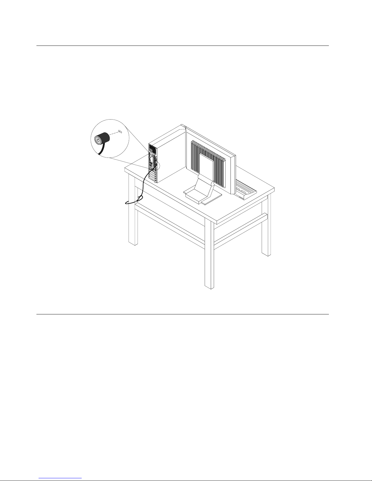
Attachinganintegratedcablelock
Anintegratedcablelock,sometimesreferredtoastheKensingtonlock,canbeusedtosecureyour
computertoadesk,table,orothernon-permanentxture.Thecablelockattachestotheintegratedcable
lockslotattherearofyourcomputerandisoperatedwithakey.Thecablelockalsolocksthebuttonsused
toopenthecomputercover.Thisisthesametypeoflockusedwithmanynotebookcomputers.Youcan
orderanintegratedcablelockdirectlyfromLenovobysearchingforKensingtonat:
http://www.lenovo.com/support
Figure8.Integratedcablelock
Usingpasswords
YoucansetavarietyofpasswordsthroughtheMicrosoftWindowsoperatingsystemandthroughtheBIOS
ofyourcomputertohelpdeterunauthorizeduseofyourcomputer.
BIOSpasswords
YoucanusetheBIOSSetupUtilityprogramtosetpasswordstopreventunauthorizedaccesstoyour
computeranddata.Thefollowingtypesofpasswordsareavailable:
•Power-OnPassword:WhenaPower-OnPasswordisset,youarepromptedtotypeavalidpassword
eachtimethecomputeristurnedon.Thecomputercannotbeuseduntilthevalidpasswordistyped
in.Formoreinformation,see“Power-OnPassword”onpage98.
•HardDiskPassword:SettingaHardDiskPasswordpreventsunauthorizedaccesstothedataonthehard
diskdrive.WhenaHardDiskPasswordisset,youarepromptedtotypeavalidpasswordeachtimeyou
trytoaccesstheharddiskdrive.Formoreinformation,see“HardDiskPassword”onpage98
.
28ThinkCentreUserGuide
Page 41

•AdministratorPassword:SettinganAdministratorPassworddetersunauthorizedusersfromchanging
congurationsettings.Ifyouareresponsibleformaintainingthecongurationsettingsofseveral
computers,youmightwanttosetanAdministratorPassword.Formoreinformation,see“Administrator
Password”onpage98
.
Youdonothavetosetanypasswordstouseyourcomputer.However,usingpasswordsimproves
computingsecurity.
Windowspasswords
DependingonyourversionoftheWindowsoperatingsystem,youcanusepasswordsforavarietyof
features,includingcontrollingloginaccess,accesstosharedresources,networkaccess,andindividualuser
settings.Formoreinformation,see“HelpandSupport”onpage127
.
Conguringthengerprintreader
Ifyourkeyboardhasangerprintreader,youcancongurethengerprintreaderintheSetupUtilityprogram.
TheFingerprintSetupsubmenuundertheSecuritymenuoftheSetupUtilityprogramprovidesthe
followingoptions:
•PrebootAuthentication:enablesordisablesthengerprintauthenticationforaccessingtheBIOS.
•EraseFingerprintData:clearsthengerprintdatastoredinangerprintreader.
Tocongurethengerprintreader,dothefollowing:
1.StarttheSetupUtilityprogram.See“StartingtheSetupUtilityprogram”onpage97.
2.FromtheSetupUtilityprogrammainmenu,selectSecurity➙FingerprintSetup,andpressEnter.
TheFingerprintSetupwindowopens.
3.SelectPrebootAuthenticationorEraseFingerprintDataasdesired,andpressEnter.
4.SelectthedesiredsettingsandpressEnter.
5.PressF10tosavechangesandexittheSetupUtilityprogram.PressEnterwhenpromptedtoconrm
theexit.
Usingandunderstandingrewalls
Arewallcanbehardware,software,oracombinationofbothdependingonthelevelofsecurityrequired.
Firewallsworkonasetofrulestodeterminewhichinboundandoutboundconnectionsareauthorized.If
yourcomputerispreintalledwitharewallprogram,ithelpsprotectagainstcomputerInternetsecurity
threats,unauthorizedaccess,intrusions,andInternetattacks.Italsoprotectsyourprivacy.Formore
informationabouthowtousetherewallprogram,refertothehelpsystemofyourrewallprogram.
TheWindowsoperatingsystempreinstalledonyourcomputerprovidestheWindowsFirewall.Fordetailson
usingtheWindowsFirewall,referto“HelpandSupport”onpage127.
Protectingdataagainstviruses
Yourcomputerispreinstalledwithanantivirusprogramtohelpyouguardagainst,detect,andeliminate
viruses.
Lenovoprovidesafullversionofantivirussoftwareonyourcomputerwithafree30-daysubscription.After
30days,youmustrenewthelicensetocontinuereceivingtheantivirussoftwareupdates.
Note:Virusdenitionlesmustbekeptup-to-datetoguardagainstnewviruses.
Chapter4.Security29
Page 42

Formoreinformationabouthowtouseyourantivirussoftware,refertothehelpsystemofyourantivirus
software.
30ThinkCentreUserGuide
Page 43

Chapter5.Installingorreplacinghardware
Thischapterprovidesinstructionsonhowtoinstallorreplacehardwareforyourcomputer.
Handlingstatic-sensitivedevices
Donotopenthestatic-protectivepackagecontainingthenewpartuntilthedefectiveparthasbeenremoved
fromthecomputerandyouarereadytoinstallthenewpart.Staticelectricity,althoughharmlesstoyou,can
seriouslydamagecomputercomponentsandparts.
Whenyouhandlepartsandothercomputercomponents,taketheseprecautionstoavoidstatic-electricity
damage:
•Limityourmovement.Movementcancausestaticelectricitytobuilduparoundyou.
•Alwayshandlepartsandothercomputercomponentscarefully.HandlePCIcards,memorymodules,
systemboards,andmicroprocessorsbytheedges.Nevertouchanyexposedcircuitry.
•Preventothersfromtouchingthepartsandothercomputercomponents.
•Beforeyoureplaceanewpart,touchthestatic-protectivepackagecontainingtheparttoametal
expansion-slotcoverorotherunpaintedmetalsurfaceonthecomputerforatleasttwoseconds.This
reducesstaticelectricityfromthepackageandyourbody.
•Whenpossible,removethenewpartfromthestatic-protectivepackaging,andinstallitdirectlyinthe
computerwithoutsettingthepartdown.Whenthisisnotpossible,placethestatic-protectivepackage
thatthepartcameinonasmooth,levelsurfaceandplacethepartonit.
•Donotplacethepartonthecomputercoverorothermetalsurface.
Installingorreplacinghardware
Thissectionprovidesinstructionsonhowtoinstallorreplacehardwareforyourcomputer.Youcanexpand
thecapabilitiesofyourcomputerandmaintainyourcomputerbyinstallingorreplacinghardware.
Attention:
Donotopenyourcomputerorattemptanyrepairbeforereadingandunderstandingthe“Importantsafetyinformation”
onpagev.
Notes:
1.UseonlycomputerpartsprovidedbyLenovo.
2.Wheninstallingorreplacinganoption,usetheappropriateinstructionsinthissectionalongwiththe
instructionsthatcomewiththeoption.
Installingexternaloptions
Youcanconnectexternaloptionstoyourcomputer,suchasexternalspeakers,aprinter,orascanner.For
someexternaloptions,youmustinstalladditionalsoftwareinadditiontomakingthephysicalconnection.
Wheninstallinganexternaloption,see“Locatingconnectors,controls,andindicatorsonthefrontofyour
computer”onpage8and“Locatingconnectorsontherearofyourcomputer”onpage9toidentifythe
requiredconnector.Then,usetheinstructionsthatcomewiththeoptiontohelpyoumaketheconnection
andinstallanysoftwareordevicedriversthatarerequiredfortheoption.
©CopyrightLenovo2012
31
Page 44

Openingthecomputercover
Attention:
Donotopenyourcomputerorattemptanyrepairbeforereadingandunderstandingthe“Importantsafetyinformation”
onpagev.
Thissectionprovidesinstructionsonhowtoopenthecomputercover.
CAUTION:
Turnoffthecomputerandwaitthreetoveminutestoletthecomputercoolbeforeopeningthe
computercover.
Toopenthecomputercover,dothefollowing:
1.Removeanymediafromthedrivesandturnoffallattacheddevicesandthecomputer.
2.Disconnectallpowercordsfromelectricaloutlets.
3.Disconnectthepowercords,Input/Outputcables,andanyothercablesthatareconnectedtothe
computer.See“Locatingconnectors,controls,andindicatorsonthefrontofyourcomputer”onpage8
and“Locatingconnectorsontherearofyourcomputer”onpage9.
4.Removeanylockingdevicethatsecuresthecomputercover,suchasanintegratedcablelock.See
“Attachinganintegratedcablelock”onpage28
.
5.Pressthecover-releasebuttonattherearofthecomputerandpivotthecomputercoverupward.
Figure9.Openingthecomputercover
Removingandreinstallingthefrontbezel
Attention:
Donotopenyourcomputerorattemptanyrepairbeforereadingandunderstandingthe“Importantsafetyinformation”
onpagev.
Thissectionprovidesinstructionsonhowtoremoveandreinstallthefrontbezel.
Toremoveandreinstallthefrontbezel,dothefollowing:
1.Removeallmediafromthedrivesandturnoffallattacheddevicesandthecomputer.Then,disconnect
allpowercordsfromelectricaloutletsanddisconnectallcablesthatareconnectedtothecomputer.
32ThinkCentreUserGuide
Page 45
2.Openthecomputercover.See“Openingthecomputercover”onpage32.
3.Removethefrontbezelbyreleasingthethreeplastictabsonthetopofthefrontbezelandpivotingthe
frontbezeloutwardtoremoveitfromthecomputer.
Figure10.Removingthefrontbezel
Chapter5.Installingorreplacinghardware33
Page 46
4.T oreinstallthefrontbezel,aligntheotherthreeplastictabsonthebottomofthefrontbezelwiththe
correspondingholesinthechassis,thenpivotthefrontbezelinwarduntilitsnapsintoposition.
Figure11.Reinstallingthefrontbezel
Whattodonext:
•Toworkwithanotherpieceofhardware,gototheappropriatesection.
•Tocompletetheinstallationorreplacement,goto“Completingthepartsreplacement”onpage87.
Accessingthesystemboardcomponentsanddrives
Attention:
Donotopenyourcomputerorattemptanyrepairbeforereadingandunderstandingthe“Importantsafetyinformation”
onpagev.
Thissectionprovidesinstructionsonhowtoaccessthesystemboardcomponentsanddrives.
Toaccessthesystemboardcomponentsanddrives,dothefollowing:
1.Removeallmediafromthedrivesandturnoffallattacheddevicesandthecomputer.Then,disconnect
allpowercordsfromelectricaloutletsanddisconnectallcablesthatareconnectedtothecomputer.
2.Openthecomputercover.See“Openingthecomputercover”onpage32.
3.Removethefrontbezel.See“Removingandreinstallingthefrontbezel”onpage32.
4.Removetheheatsinkfanduct.See“Replacingtheheatsinkandfanassembly”onpage59.
5.Removetheharddiskdrive.See“Replacingtheharddiskdrive”onpage54.
34ThinkCentreUserGuide
Page 47

6.Pivottheopticaldrivebayupwardtoaccessthesystemboardcomponentsandthecables.See
“Replacingtheopticaldrive”onpage56.
Installingorreplacingamemorymodule
Attention:
Donotopenyourcomputerorattemptanyrepairbeforereadingandunderstandingthe“Importantsafetyinformation”
onpagev.
Thissectionprovidesinstructionsonhowtoinstallorreplaceamemorymodule.
YourcomputerhasfourslotsforinstallingorreplacingDDR3UDIMMsthatprovideuptoamaximumof
32GBsystemmemory.Wheninstallingorreplacingamemorymodule,use2GB,4GB,or8GBDDR3
UDIMMsinanycombinationuptoamaximumof32GB.
Thefollowingtableprovidesinformationaboutthememorymoduleinstallationrulesthatyoushould
considerwheninstallingorremovingamemorymodule.The“X”markindicatesthememoryslot(s)into
whichthememorymodule(s)shouldbeinstalledindifferentsituations.Thenumbers1,2,3,and4indicate
theinstallationsequence.T olocatethememorymoduleslots,see“Locatingpartsonthesystemboard”
onpage11
.
UDIMMDIMM1DIMM2DIMM3DIMM4
OneUDIMM
X
TwoUDIMMsX,1X,2
ThreeUDIMMsX,3X,1X,2
FourUDIMMsX,3X,1X,4X,2
Toinstallorreplaceamemorymodule,dothefollowing:
1.T urnoffthecomputeranddisconnectallpowercordsfromelectricaloutlets.
2.Openthecomputercover.See“Openingthecomputercover”onpage32.
3.Removethefrontbezel.See“Removingandreinstallingthefrontbezel”onpage32.
4.Removetheheatsinkfanduct.See“Replacingtheheatsinkandfanassembly”onpage59.
5.Removetheharddiskdrive.See“Replacingtheharddiskdrive”onpage54.
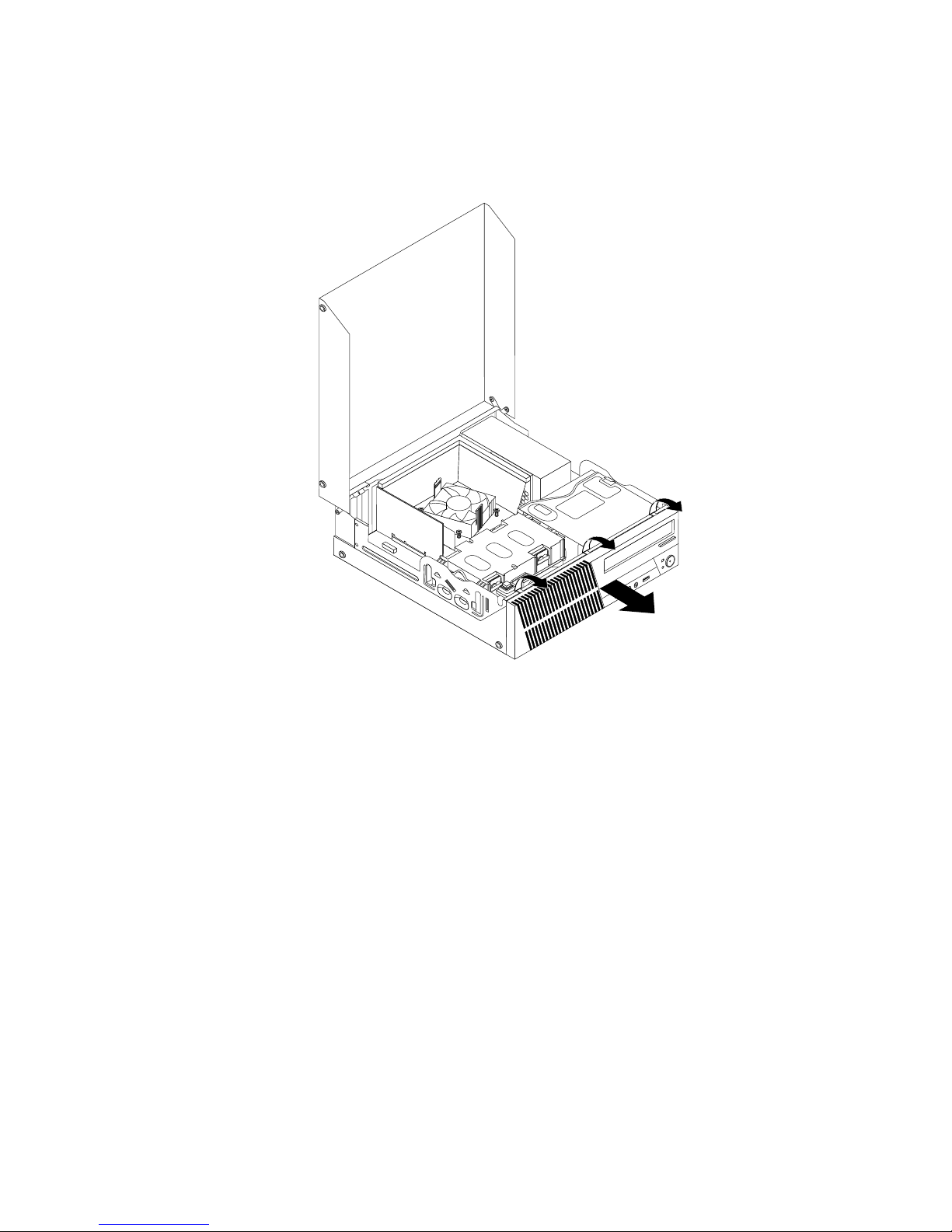
6.Pivottheopticaldrivebayupwardtogainaccesstothememoryslots.See“Replacingtheoptical
drive”onpage56.
7.Locatethememoryslots.See“Locatingpartsonthesystemboard”onpage11.
8.Removeanypartsthatmightpreventaccesstothememoryslots.
9.Dependingonwhetheryouareinstallingorreplacingamemorymodule,dooneofthefollowing:
Chapter5.Installingorreplacinghardware35
Page 48

•Ifyouarereplacinganoldmemorymodule,opentheretainingclipsandgentlypullthememory
moduleoutofthememoryslot.
Figure12.Removingamemorymodule
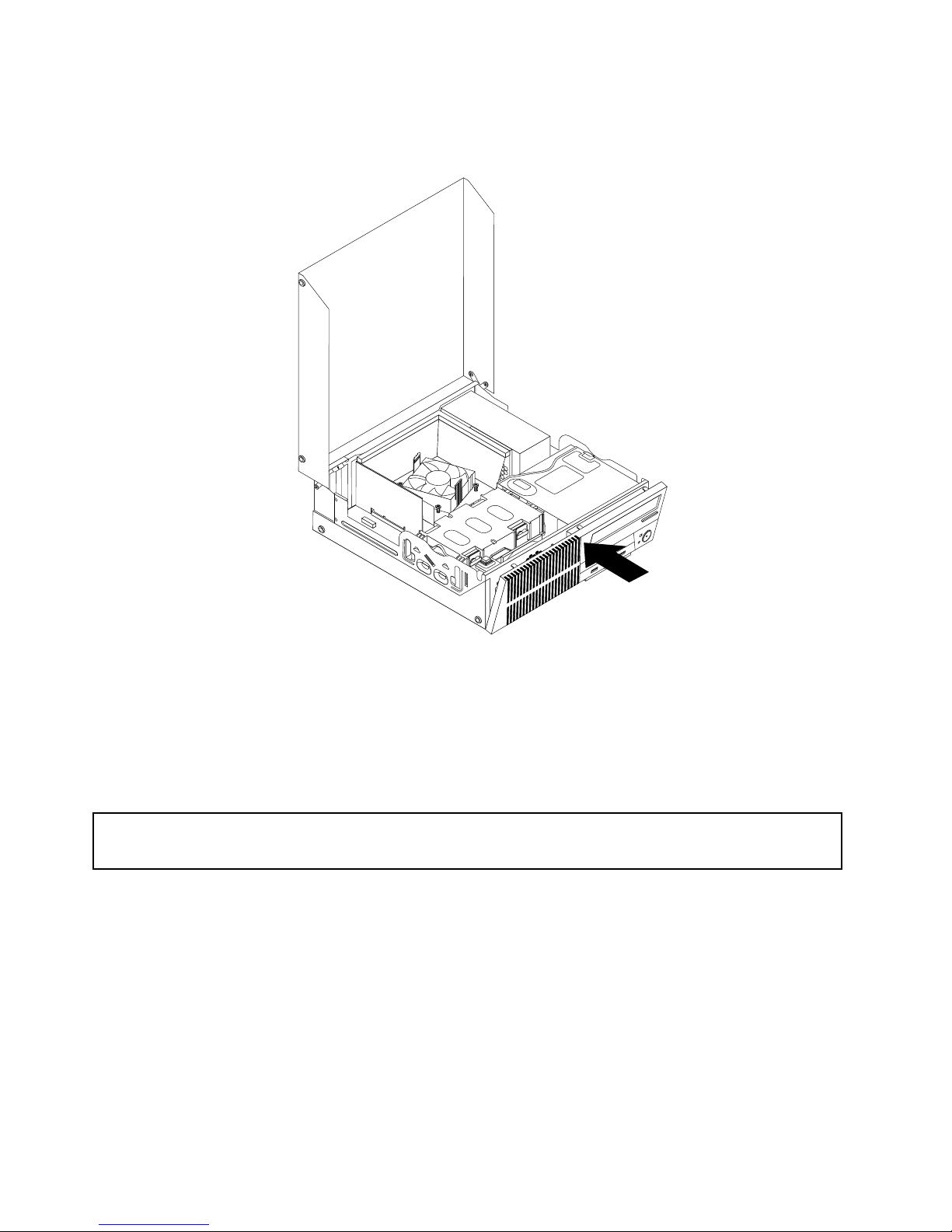
•Ifyouareinstallingamemorymodule,opentheretainingclipsofthememoryslotintowhichyou
wanttoinstallthememorymodule.
Figure13.Openingtheretainingclips
36ThinkCentreUserGuide
Page 49
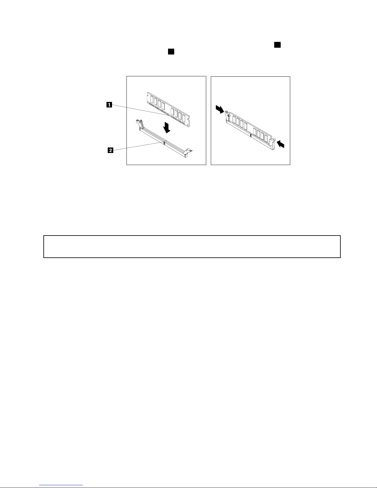
10.Positionthenewmemorymoduleoverthememoryslot.Ensurethatthenotch1onthememory
modulealignscorrectlywiththeslotkey2onthesystemboard.Pushthememorymodulestraight
downintotheslotuntiltheretainingclipsclose.
Figure14.Installingamemorymodule
Whattodonext:
•Toworkwithanotherpieceofhardware,gototheappropriatesection.
•Tocompletetheinstallationorreplacement,goto“Completingthepartsreplacement”onpage87.
InstallingorreplacingaPCIcard
Attention:
Donotopenyourcomputerorattemptanyrepairbeforereadingandunderstandingthe“Importantsafetyinformation”
onpagev.
ThissectionprovidesinstructionsonhowtoinstallorreplaceaPCIcard.Y ourcomputerhastwostandard
PCIcardslots,onePCIExpressx1cardslot,andonePCIExpressx16graphicscardslot.
ToinstallorreplaceaPCIcard,dothefollowing:
1.T urnoffthecomputeranddisconnectallpowercordsfromelectricaloutlets.
2.Openthecomputercover.See“Openingthecomputercover”onpage32.
3.RotatethePCIcardretainertotheopenposition.
4.DependingonwhetheryouareinstallingorreplacingaPCIcard,dooneofthefollowing:
•IfyouareinstallingaPCIcard,removetheappropriatemetalslotcover.
•IfyouarereplacinganoldPCIcard,grasptheoldcardthatiscurrentlyinstalledandgentlypullit
outoftheslot.
Chapter5.Installingorreplacinghardware37
Page 50

Figure15.RemovingaPCIcard
Notes:
a.Thecardtstightlyintothecardslot.Ifnecessary,alternatemovingeachsideofthecardasmall
amountuntilitisremovedfromthecardslot.
b.Ifthecardisheldinplacebyaretaininglatch,pressthecardretaininglatch1asshownto
disengagethelatch.Graspthecardandgentlypullitoutoftheslot.
5.RemovethenewPCIcardfromitsstatic-protectivepackage.
38ThinkCentreUserGuide
Page 51
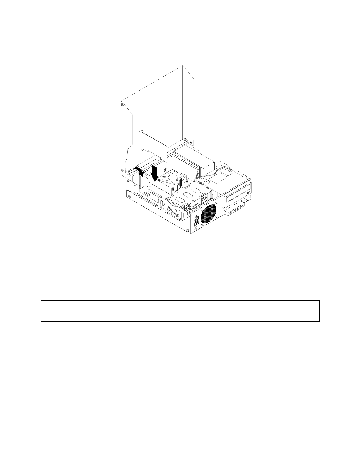
6.Installthenewcardintotheappropriatecardslotonthesystemboardandrotatethecardretainertothe
closedposition.See“Locatingpartsonthesystemboard”onpage11.
Figure16.InstallingthePCIcard
Whattodonext:
•Toworkwithanotherpieceofhardware,gototheappropriatesection.
•Tocompletetheinstallationorreplacement,goto“Completingthepartsreplacement”onpage87
.
Installingorreplacingthecardreader
Attention:
Donotopenyourcomputerorattemptanyrepairbeforereadingandunderstandingthe“Importantsafetyinformation”
onpagev.
Thissectionprovidesinstructionsonhowtoinstallorreplacethecardreader.
Note:Thecardreaderisonlyavailableinsomemodels.Fornewinstallation,see“Installingthecardreader”
onpage39
.Forreplacement,see“Replacingthecardreader”onpage42.
Installingthecardreader
Toinstallthecardreader,dothefollowing:
1.Removeallmediafromthedrivesandturnoffallattacheddevicesandthecomputer.Then,disconnect
allpowercordsfromelectricaloutletsanddisconnectallcablesthatareconnectedtothecomputer.
2.Openthecomputercover.See“Openingthecomputercover”onpage32.
3.Removethefrontbezel.See“Removingandreinstallingthefrontbezel”onpage32.
4.Locatethecardreaderdrivebay.See“Locatinginternaldrives”onpage14.
Chapter5.Installingorreplacinghardware39
Page 52
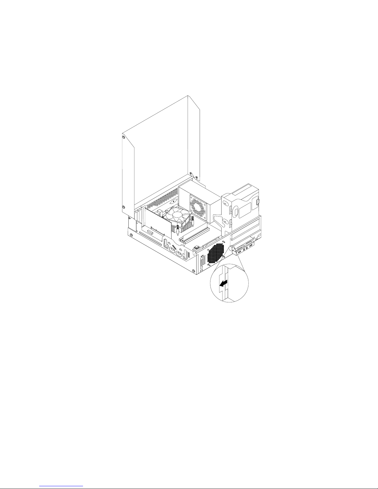
Note:Youmighthavetoremovethemetalcoverofthecardreaderdrivebay.
5.Installthenewcardreaderintothecardreaderbracket.Theninstallthetwoscrewstosecurethe
cardreadertothebracket.
6.Installthecardreaderbrackettothechassis.Thenpushthebrackettothelefttoalignthescrewholein
thebracketwiththecorrespondingholeinthechassis.
Figure17.Installingthecardreader
40ThinkCentreUserGuide
Page 53

7.Installthescrewtosecurethecardreaderbrackettothechassis.
Figure18.Installingthescrewthatsecuresthecardreader
8.ConnectthecardreadercabletooneoftheUSBconnectorsonthesystemboard.See“Locating
partsonthesystemboard”onpage11
.
9.Pivottheopticaldrivebaydownwarduntilitsnapsintoposition.
10.Reinstallthefrontbezel.See“Removingandreinstallingthefrontbezel”onpage32.
Note:Youmighthavetoremovethecardreadercover2fromthefrontbezel.Toremovethecardread
cover,pivotthetworetainingclips1thatsecurethecardreadercoveroutwardsandthencompletely
disengagethecardreadercoverfromthefrontbezel.
Figure19.Removingthecardreadercover
Whattodonext:
•Toworkwithanotherpieceofhardware,gototheappropriatesection.
•Tocompletetheinstallationorreplacement,goto“Completingthepartsreplacement”onpage87.
Chapter5.Installingorreplacinghardware41
Page 54
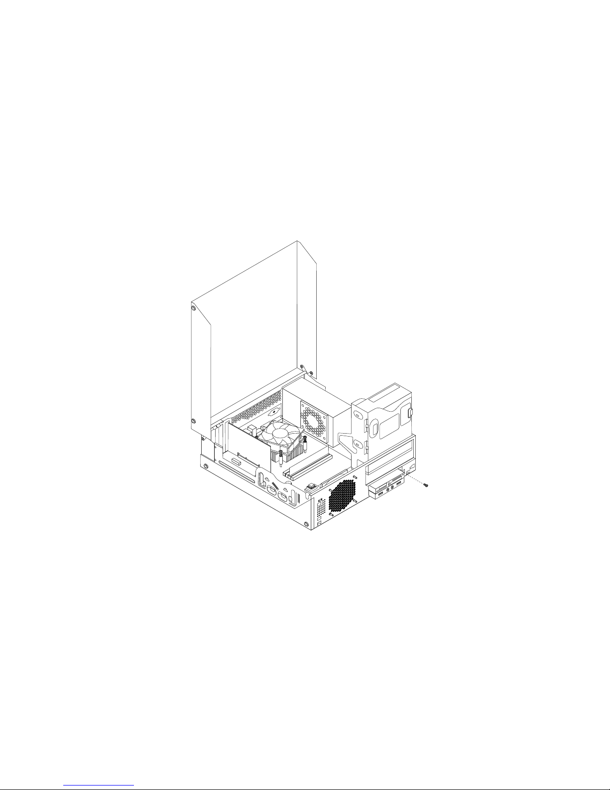
Replacingthecardreader
Toreplacethecardreader,dothefollowing:
1.Removeallmediafromthedrivesandturnoffallattacheddevicesandthecomputer.Then,disconnect
allpowercordsfromelectricaloutletsanddisconnectallcablesthatareconnectedtothecomputer.
2.Openthecomputercover.See“Openingthecomputercover”onpage32.
3.Removethefrontbezel.See“Removingandreinstallingthefrontbezel”onpage32.
4.Locatethecardreaderdrivebay.See“Locatinginternaldrives”onpage14.
5.PivottheopticaldrivebayupwardanddisconnectthecardreadercablefromtheUSBconnectoronthe
systemboard.See“Locatingpartsonthesystemboard”onpage11.
6.Removethescrewthatsecuresthecardreaderbracket.Then,removethecardreaderbracketfrom
thechassis.
Figure20.Removingthescrewthatsecuresthecardreader
7.Removethetwoscrewsthatsecurethecardreadertoitsbracket.Thenremovethefailingcardreader
fromthebracket.
8.Installanewcardreaderintothebracketandinstallthetwoscrewstosecurethecardreadertothe
bracket.
42ThinkCentreUserGuide
Page 55

9.Installthecardreaderbrackettothechassis.Thenpushthebrackettothelefttoalignthescrewholein
thebracketwiththecorrespondingholeinthechassis.
Figure21.Installingthecardreader
Chapter5.Installingorreplacinghardware43
Page 56

10.Installthescrewtosecurethecardreaderbrackettothechassis.
Figure22.Installingthescrewthatsecuresthecardreader
11.ReconnectthecardreadercabletooneoftheUSBconnectorsonthesystemboard.See“Locating
partsonthesystemboard”onpage11
.
12.Pivottheopticaldrivebaydownwarduntilitsnapsintoposition.
13.Reinstallthefrontbezel.See“Removingandreinstallingthefrontbezel”onpage32.
Whattodonext:
•Toworkwithanotherpieceofhardware,gototheappropriatesection.
•Tocompletetheinstallationorreplacement,goto“Completingthepartsreplacement”onpage87
.
InstallingorreplacingthemSA T Asolidstatedrive
Attention:
Donotopenyourcomputerorattemptanyrepairbeforereadingandunderstandingthe“Importantsafetyinformation”
onpagev.
ThissectionprovidesinstructionsonhowtoinstallorreplacethemSATAsolidstatedrive.
Note:ThemSATAsolidstatedriveisonlyavailableinsomemodels.Fornewinstallation,see“Installing
themSATAsolidstatedrive”onpage44.Forreplacement,see“ReplacingthemSATAsolidstatedrive”
onpage47.
InstallingthemSATAsolidstatedrive
ToinstallthemSATAsolidstatedrive,dothefollowing:
44ThinkCentreUserGuide
Page 57

1.Removeallmediafromthedrivesandturnoffallattacheddevicesandthecomputer.Then,disconnect
allpowercordsfromelectricaloutletsanddisconnectallcablesthatareconnectedtothecomputer.
2.Openthecomputercover.See“Openingthecomputercover”onpage32.
3.Removethefrontbezel.See“Removingandreinstallingthefrontbezel”onpage32.
4.LocatethemSATAsolidstatedrivebay.See“Locatinginternaldrives”onpage14.
Note:YoumighthavetoremovethemetalcoverofthemSATAsolidstatedrivebay.
5.InsertthemSATAsolidstatedriveintotheminiPCIExpressslotonthestorageconverter,andthen
pressthemSATAsolidstatedrivedownward.
Figure23.InstallingthemSATAsolidstatedriveintothestorageconverter
6.InstallthetwoscrewstosecurethemSATAsolidstatedrivetothestorageconverter.
Figure24.InstallingthescrewsthatsecurethemSATAsolidstatedrive
7.InsertthemSATAsolidstatedrivestorageconverterintothechassis.Thenpushthestorageconverter
tothelefttoalignthescrewholeinthestorageconverterwiththecorrespondingholeinthechassis.
Chapter5.Installingorreplacinghardware45
Page 58

Figure25.InstallingthemSA TAsolidstatedrivestorageconverter
8.InstallthescrewtosecurethemSATAsolidstatedrivestorageconvertertothechassis.
46ThinkCentreUserGuide
Page 59
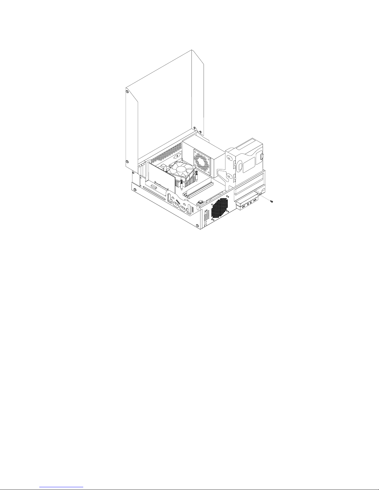
Figure26.InstallingthescrewthatsecuresthemSATAsolidstatedrivestorageconverter
9.ConnectthesignalcableandthepowercabletothemSATAsolidstatedrive.
10.Pivottheopticaldrivebaydownwarduntilitsnapsintoposition.
11.Reinstallthefrontbezel.See“Removingandreinstallingthefrontbezel”onpage32.
Whattodonext:
•Toworkwithanotherpieceofhardware,gototheappropriatesection.
•Tocompletetheinstallationorreplacement,goto“Completingthepartsreplacement”onpage87.
ReplacingthemSATAsolidstatedrive
ToreplacethemSATAsolidstatedrive,dothefollowing:
1.Removeallmediafromthedrivesandturnoffallattacheddevicesandthecomputer.Then,disconnect
allpowercordsfromelectricaloutletsanddisconnectallcablesthatareconnectedtothecomputer.
2.Openthecomputercover.See“Openingthecomputercover”onpage32.
3.Removethefrontbezel.See“Removingandreinstallingthefrontbezel”onpage32.
4.LocatethemSATAsolidstatedrivebay.See“Locatinginternaldrives”onpage14.
5.PivottheopticaldrivebayupwardanddisconnectthecardreadercablefromtheUSBconnectoronthe
systemboard.See“Locatingpartsonthesystemboard”onpage11
.
6.DisconnectthesignalcableandpowercablefromthemSATAsolidstatedrive.
7.RemovethescrewthatsecuresthemSATAsolidstatedrivestorageconverter.Then,removethe
storageconverterfromthechassis.
Chapter5.Installingorreplacinghardware47
Page 60

Figure27.RemovingthemSATAsolidstatedrivestorageconverter
8.RemovethetwoscrewsthatsecurethemSATAsolidstatedrivefromthestorageconverter.
Figure28.RemovingthescrewsthatsecurethemSATAsolidstatedrive
48ThinkCentreUserGuide
Page 61

9.RemovethemSATAsolidstatedrivefromtheminiPCIExpressslotonthestorageconverter.
Figure29.RemovingthemSATAsolidstatedrive
10.T oinstallanewmSATAsolidstatedrive,insertthemSATAsolidstatedriveintotheminiPCIExpressslot
onthestorageconverter,andthenpressthemSATAsolidstatedrivedownward.
Figure30.InstallingthemSATAsolidstatedriveintothestorageconverter
11.InstallthetwoscrewstosecurethemSATAsolidstatedrivetothestorageconverter.
Figure31.InstallingthescrewsthatsecurethemSATAsolidstatedrive
Chapter5.Installingorreplacinghardware49
Page 62

12.InsertthemSATAsolidstatedrivestorageconverterintothechassis.Thenpushtheconvertertotheleft
toalignthescrewholeintheconverterwiththecorrespondingholeinthechassis.
Figure32.InstallingthemSA TAsolidstatedrivestorageconverter
50ThinkCentreUserGuide
Page 63
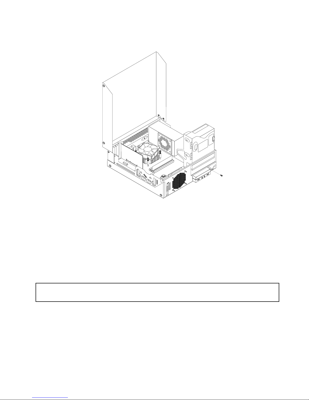
13.InstallthescrewtosecurethemSATAsolidstatedrivestorageconvertertothechassis.
Figure33.Installingthescrewthatsecuresthestorageconverter
14.ConnectthesignalcableandthepowercabletothemSATAsolidstatedrive.
15.Pivottheopticaldrivebaydownwarduntilitsnapsintoposition.
16.Reinstallthefrontbezel.See“Removingandreinstallingthefrontbezel”onpage32.
Whattodonext:
•Toworkwithanotherpieceofhardware,gototheappropriatesection.
•Tocompletetheinstallationorreplacement,goto“Completingthepartsreplacement”onpage87.
Replacingthebattery
Attention:
Donotopenyourcomputerorattemptanyrepairbeforereadingandunderstandingthe“Importantsafetyinformation”
onpagev.
Yourcomputerhasaspecialtypeofmemorythatmaintainsthedate,time,andsettingsforbuilt-infeatures,
suchasparallel-portassignments(conguration).Abatterykeepsthisinformationactivewhenyouturn
offthecomputer.
Thebatterynormallyrequiresnochargingormaintenancethroughoutitslife;however,nobatterylasts
forever.Ifthebatteryfails,thedate,time,andcongurationinformation(includingpasswords)arelost.An
errormessageisdisplayedwhenyouturnonthecomputer.
Chapter5.Installingorreplacinghardware51
Page 64

Refertothe“Lithiumbatterynotice”intheSafetyandWarrantyGuideforinformationaboutreplacing
anddisposingofthebattery.
Toreplacethebattery,dothefollowing:
1.T urnoffthecomputeranddisconnectallpowercordsfromelectricaloutlets.
2.Openthecomputercover.See“Openingthecomputercover”onpage32.
3.Locatethebattery.See“Locatingpartsonthesystemboard”onpage11.
4.Removetheoldbattery.
Figure34.Removingtheoldbattery
5.Installanewbattery.
Figure35.Installinganewbattery
6.Closethecomputercoverandconnectthecables.See“Completingthepartsreplacement”onpage87.
Note:Whenthecomputeristurnedonforthersttimeafterreplacingthebattery,anerrormessage
mightbedisplayed.Thisisnormalafterreplacingthebattery.
7.T urnonthecomputerandallattacheddevices.
8.UsetheSetupUtilityprogramtosetthedate,time,andanypasswords.SeeChapter7“UsingtheSetup
Utilityprogram”onpage97
.
Whattodonext:
•Toworkwithanotherpieceofhardware,gototheappropriatesection.
•Tocompletetheinstallationorreplacement,goto“Completingthepartsreplacement”onpage87.
Installingthesolidstatedrive
Attention:
Donotopenyourcomputerorattemptanyrepairbeforereadingandunderstandingthe“Importantsafetyinformation”
onpagev
.
Thissectionprovidesinstructionsonhowtoinstallthe2.5-inchsolidstatedriveintothe3.5-inchhard
diskdrivebracket.
52ThinkCentreUserGuide
Page 65

Toinstallthesolidstatedrive,dothefollowing:
1.Installthesolidstatedriveintotheadapter.Then,installthefourscrewstosecurethesolidstate
drivetotheadapter.
Figure36.Installingthesolidstatedriveintotheadapter
2.T oinstallthesolidstatedrivewiththeadapterintothe3.5-inchharddiskdrivebracket,exthebracket
andalignpin1,pin2,pin3,andpin4onthebracketwiththecorrespondingholesintheadapter.
Figure37.Installingthesolidstatedrivewiththeadapterintotheharddiskdrivebracket
3.Connectthesignalcableandthepowercabletothesolidstatedrive.
4.Installthesolidstatedriveintotheharddiskdrivebay.See“Replacingtheharddiskdrive”onpage54.
Chapter5.Installingorreplacinghardware53
Page 66

Whattodonext:
•Toworkwithanotherpieceofhardware,gototheappropriatesection.
•Tocompletetheinstallationorreplacement,goto“Completingthepartsreplacement”onpage87.
Replacingtheharddiskdrive
Attention:
Donotopenyourcomputerorattemptanyrepairbeforereadingandunderstandingthe“Importantsafetyinformation”
onpagev.
Thissectionprovidesinstructionsonhowtoreplacetheharddiskdrive.
Note:Dependingonyourmodeltype,yourcomputermightcomewitha2.5-inchsolidstatedrive.Toinstall
thesolidstatedrive,see“Installingthesolidstatedrive”onpage52.
Toreplacetheharddiskdrive,dothefollowing:
1.T urnoffthecomputeranddisconnectallpowercordsfromelectricaloutlets.
2.Openthecomputercover.See“Openingthecomputercover”onpage32.
3.Locatetheharddiskdrive.See“Locatingcomponents”onpage11.
4.Pullonthehandleoftheharddiskdrivebracketasshownandthenlifttheharddiskdrivebracket
upfromtheopticaldrivebay.
Figure38.Removingtheharddiskdrive
5.Disconnectthesignalcableandthepowercablefromtheharddiskdrivetocompletelyremovethehard
diskdrivefromthechassis.
54ThinkCentreUserGuide
Page 67
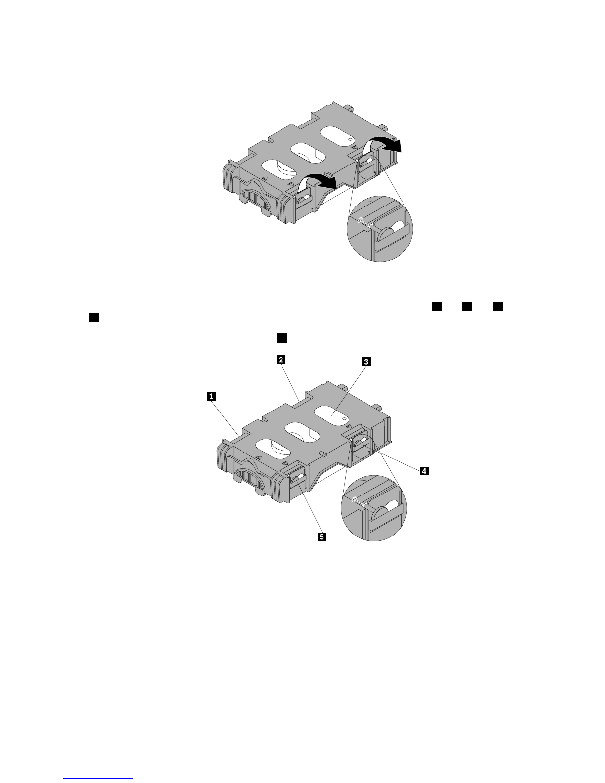
6.Flextheretainingclipsasshowntoremovetheharddiskdrivefromthebracket.
Figure39.Removingtheharddiskdrivefromthebracket
7.T oinstallanewharddiskdriveintothebracket,exthebracketandalignpin1,pin2,pin4,andpin
5onthebracketwiththecorrespondingholesintheharddiskdrive.
Important:Donottouchthecircuitboard
3onthebottomoftheharddiskdrive.
8.Connectthesignalcableandthepowercabletothenewharddiskdrive.
Chapter5.Installingorreplacinghardware55
Page 68

9.Insertthetworetainingclips1oftheharddiskdrivebracketintothecorrespondingholesintheside
oftheopticaldrivebay,andthenpivottheharddiskdriveandbracketdownwardsuntilthehard
diskdrivebracketsnapsintoposition.
Figure40.Installingtheharddiskdrive
Whattodonext:
•Toworkwithanotherpieceofhardware,gototheappropriatesection.
•Tocompletetheinstallationorreplacement,goto“Completingthepartsreplacement”onpage87.
Replacingtheopticaldrive
Attention:
Donotopenyourcomputerorattemptanyrepairbeforereadingandunderstandingthe“Importantsafetyinformation”
onpagev.
Thissectionprovidesinstructionsonhowtoreplacetheopticaldrive.
Toreplacetheopticaldrive,dothefollowing:
1.T urnoffthecomputeranddisconnectallpowercordsfromelectricaloutlets.
2.Openthecomputercover.See“Openingthecomputercover”onpage32.
3.Removethefrontbezel.See“Removingandreinstallingthefrontbezel”onpage32.
4.Removetheharddiskdrive.See“Replacingtheharddiskdrive”onpage54.
56ThinkCentreUserGuide
Page 69

5.Presstheblueretainingcliptopivottheopticaldrivebayupward.
Figure41.Pivotingtheopticaldrivebay
6.Disconnectthesignalcableandthepowercablefromtherearoftheopticaldrive.
Chapter5.Installingorreplacinghardware57
Page 70

7.Presstheopticaldrivelock1andslidetheopticaldriveoutoftherearofthedrivebayassembly.
Figure42.Removingtheoldopticaldrive
8.Installtheopticaldriveretaineronthesideofthenewopticaldrive.
Figure43.Installingtheopticaldriveretainer
58ThinkCentreUserGuide
Page 71
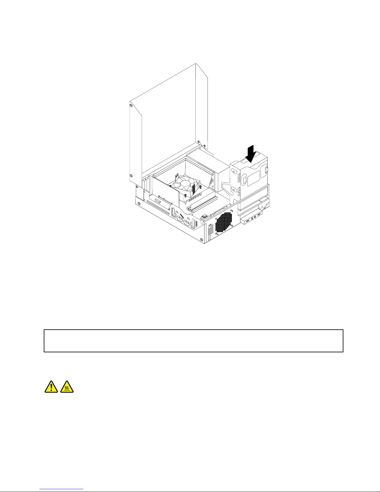
9.Slidethenewopticaldriveintothedrivebayuntilitsnapsintoposition.
Figure44.Installinganewopticaldrive
10.Connectthesignalcableandthepowercabletotherearoftheopticaldrive.
Whattodonext:
•Toworkwithanotherpieceofhardware,gototheappropriatesection.
•Tocompletetheinstallationorreplacement,goto“Completingthepartsreplacement”onpage87.
Replacingtheheatsinkandfanassembly
Attention:
Donotopenyourcomputerorattemptanyrepairbeforereadingandunderstandingthe“Importantsafetyinformation”
onpagev.
Thissectionprovidesinstructionsonhowtoreplacetheheatsinkandfanassembly.
CAUTION:
Theheatsinkandfanassemblymightbeveryhot.Turnoffthecomputerandwaitthreetove
minutestoletthecomputercoolbeforeremovingthecomputercover.
Toreplacetheheatsinkandfanassembly,dothefollowing:
1.Removeallmediafromthedrivesandturnoffallattacheddevicesandthecomputer.Then,disconnect
allpowercordsfromelectricaloutletsanddisconnectallcablesthatareconnectedtothecomputer.
2.Openthecomputercover.See“Openingthecomputercover”onpage32.
Chapter5.Installingorreplacinghardware59
Page 72
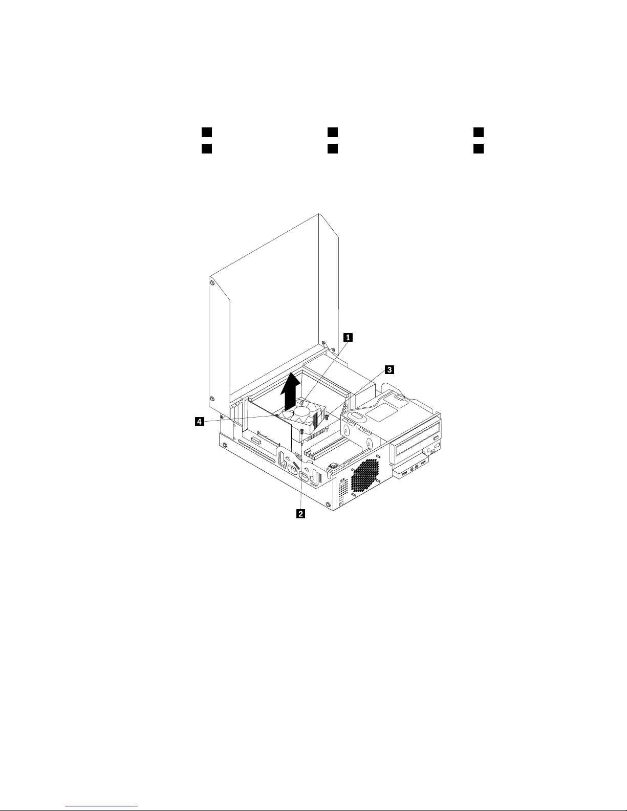
3.Disconnecttheheatsinkandfanassemblycablefromthemicroprocessorfanconnectoronthesystem
board.See“Locatingpartsonthesystemboard”onpage11.
4.Followthissequencetoremovethefourscrewsthatsecuretheheatsinkandfanassemblytothe
systemboard:
a.Partiallyremovescrew1,thenfullyremovescrew2,andthenfullyremovescrew1.
b.Partiallyremovescrew3,thenfullyremovescrew4,andthenfullyremovescrew3.
Note:Carefullyremovethefourscrewsfromthesystemboardtoavoidanypossibledamagetothe
systemboard.Thefourscrewscannotberemovedfromtheheatsinkandfanassembly.
Figure45.Screwsthatsecuretheheatsinkandfanassembly
5.Lifttheheatsinkandfanassemblywiththefanductoffthesystemboard.
Notes:
a.Youmighthavetogentlytwisttheheatsinkandfanassemblytofreeitfromthemicroprocessor.
b.Whenhandlingtheheatsinkandfanassembly,donottouchthethermalgreaseonthebottom
oftheheatsinkandfanassembly.
60ThinkCentreUserGuide
Page 73

6.Pivotthetwoplasticretainingclipsthatsecuretheheatsinkfanductoutward.Thenremovetheheat
sinkfanductfromthefailingheatsinkandfanassembly.
Figure46.Removingtheheatsinkfanduct
7.Placethenewheatsinkandfanassemblyonthesystemboardsothatthefourscrewsarealigned
withthecorrespondingholesinthesystemboard.Ensurethatyouproperlyplacethenewheatsink
andfanassemblysothatyoucaneasilyconnectthenewheatsinkandfanassemblycabletothe
microprocessorfanconnectoronthesystemboard.
8.Followthissequencetoinstallthefourscrewstosecurethenewheatsinkandfanassembly,asshown
inFigure45“Screwsthatsecuretheheatsinkandfanassembly”onpage60:
a.Partiallytightenscrew1,thenfullytightenscrew2,andthenfullytightenscrew1.
b.Partiallytightenscrew3,thenfullytightenscrew4,andthenfullytightenscrew3.
9.Connectthenewheatsinkandfanassemblycabletothemicroprocessorfanconnectoronthesystem
board.See“Locatingpartsonthesystemboard”onpage11.
Chapter5.Installingorreplacinghardware61
Page 74

10.Lowerandpositiontheheatsinkfanductonthetopoftheheatsinkandfanassemblyuntilitsnaps
intoposition.
Figure47.Installingtheheatsinkfanduct
Whattodonext:
•Toworkwithanotherpieceofhardware,gototheappropriatesection.
•Tocompletethereplacement,goto“Completingthepartsreplacement”onpage87.
Replacingthepowersupplyassembly
Attention:
Donotopenyourcomputerorattemptanyrepairbeforereadingandunderstandingthe“Importantsafetyinformation”
onpagev.
Thissectionprovidesinstructionsonhowtoreplacethepowersupplyassembly.
Althoughtherearenomovingpartsinyourcomputerafterthepowercordhasbeendisconnected,the
followingwarningsarerequiredforyoursafetyandproperUnderwritersLaboratories(UL)certication.
CAUTION:
62ThinkCentreUserGuide
Page 75

Hazardousmovingparts.Keepngersandotherbodypartsaway.
CAUTION:
Neverremovethecoveronapowersupplyoranypartthathasthefollowinglabelattached.
Hazardousvoltage,current,andenergylevelsarepresentinsideanycomponentthathasthislabel
attached.Therearenoserviceablepartsinsidethesecomponents.Ifyoususpectaproblemwith
oneoftheseparts,contactaservicetechnician.
Toreplacethepowersupplyassembly,dothefollowing:
1.Removeallmediafromthedrivesandturnoffallattacheddevicesandthecomputer.Then,disconnect
allpowercordsfromelectricaloutletsanddisconnectallcablesthatareconnectedtothecomputer.
2.Openthecomputercover.See“Openingthecomputercover”onpage32.
3.Removethefrontbezel.See“Removingandreinstallingthefrontbezel”onpage32.
4.Removetheharddiskdrive.See“Replacingtheharddiskdrive”onpage54.
Chapter5.Installingorreplacinghardware63
Page 76
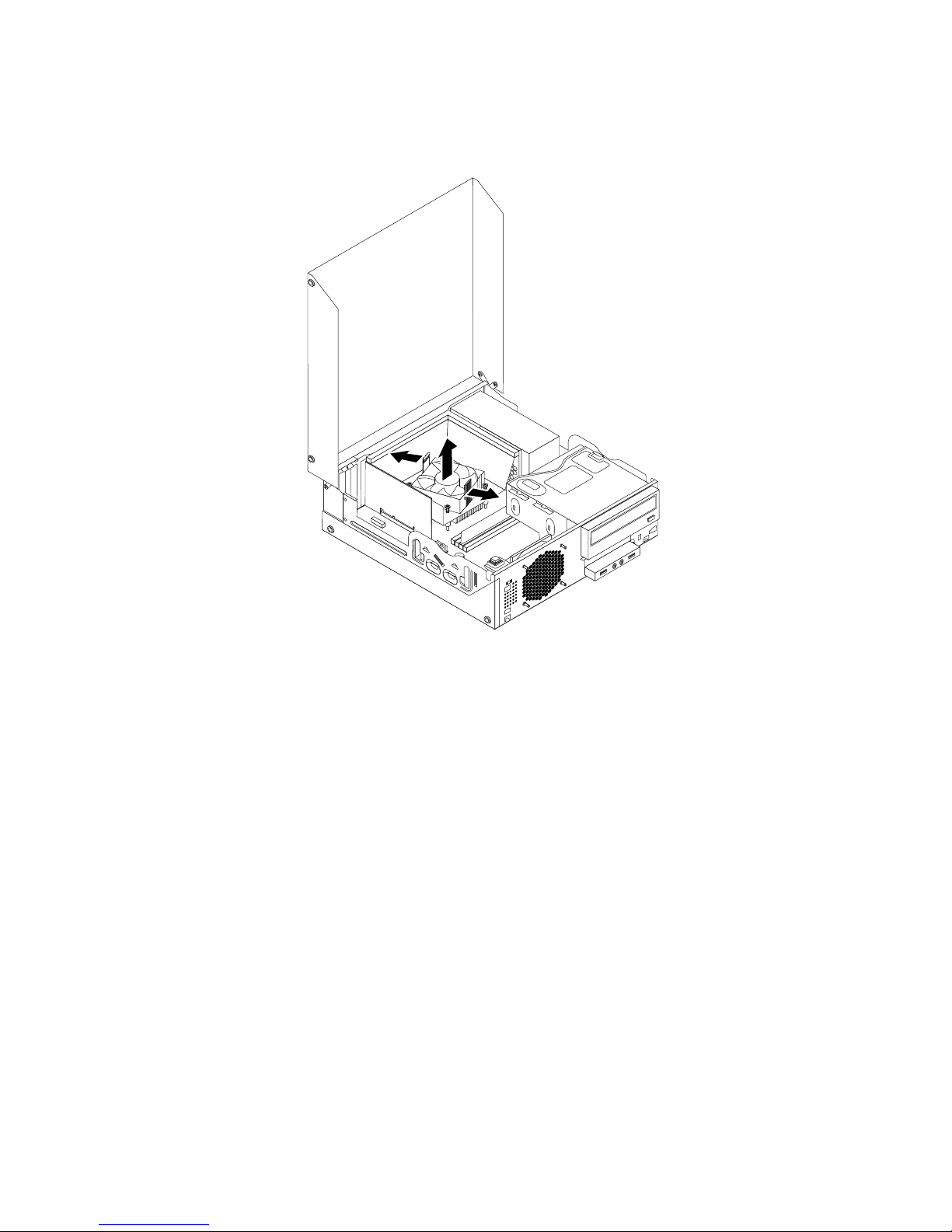
5.Pivotthetwoplasticretainingclipsthatsecuretheheatsinkfanductoutward,andthenlifttheheatsink
fanductoutofthechassis.
Figure48.Removingtheheatsinkfanduct
64ThinkCentreUserGuide
Page 77

6.Pivottheopticaldriveupwardanddisconnectthepowersupplyassemblycablesfromalldrivesand
frompowerconnectors1,2and3onthesystemboard.
Figure49.Powerconnectorsonthesystemboard
Note:Youmightalsoneedtoreleasethepowersupplyassemblycablesfromsomecableclipsorties
thatsecurethecablestothechassis.Ensurethatyounotethecableroutingbeforedisconnecting
thecables.
Chapter5.Installingorreplacinghardware65
Page 78

7.Attherearofthecomputer,removethethreescrewsthatsecurethepowersupplyassembly.Pressthe
powersupplyclip1downwardtoreleasethepowersupplyassemblyandthenslidethepowersupply
assemblytothefrontofthecomputer.Liftthepowersupplyassemblyoutofthecomputer.
3 4
5 6
7 8
Figure50.Removingthepowersupplyassembly
8.Ensurethatthenewpowersupplyassemblyisthecorrectreplacement.
9.Installthenewpowersupplyassemblyintothechassissothatthescrewholesinthenewpowersupply
assemblyarealignedwiththecorrespondingholesintherearofthechassis.Then,installthethree
screwstosecurethenewpowersupplyassemblyinplace.
Note:UseonlyscrewsprovidedbyLenovo.
3 4
5 6
7 8
Figure51.Installingthepowersupplyassembly
10.Connectthenewpowersupplyassemblycablestoalldrivesandthesystemboard.See“Locating
partsonthesystemboard”onpage11.
66ThinkCentreUserGuide
Page 79

11.Lowerandpositiontheheatsinkfanductonthetopoftheheatsinkandfanassemblyuntilitsnaps
intoposition.
Figure52.Installingtheheatsinkfanduct
Whattodonext:
•Toworkwithanotherpieceofhardware,gototheappropriatesection.
•Tocompletethereplacement,goto“Completingthepartsreplacement”onpage87.
Replacingthemicroprocessor
Attention:
Donotopenyourcomputerorattemptanyrepairbeforereadingandunderstandingthe“Importantsafetyinformation”
onpagev.
Thissectionprovidesinstructionsonhowtoreplacethemicroprocessor.
CAUTION:
Theheatsinkandmicroprocessormightbeveryhot.T urnoffthecomputerandwaitthreetove
minutestoletthecomputercoolbeforeremovingthecomputercover.
Toreplacethemicroprocessor,dothefollowing:
1.Removeallmediafromthedrivesandturnoffallattacheddevicesandthecomputer.Then,disconnect
allpowercordsfromelectricaloutletsanddisconnectallcablesthatareconnectedtothecomputer.
2.Openthecomputercover.See“Openingthecomputercover”onpage32.
Chapter5.Installingorreplacinghardware67
Page 80

3.Locatethesystemboardanddisconnectallcablesconnectedtothesystemboard.See“Locating
partsonthesystemboard”onpage11.
4.Removetheheatsinkandfanassemblywiththefanduct.See“Replacingtheheatsinkandfan
assembly”onpage59.
Note:Donotletthethermalgreaseonthebottomoftheheatsinkandfanassemblygetincontact
withanything.
5.Liftthesmallhandle1andopentheretainer2toaccessthemicroprocessor3.
Figure53.Accessingthemicroprocessor
6.Liftthemicroprocessorstraightupandoutofthemicroprocessorsocket.
Figure54.Removingthemicroprocessor
Notes:
a.Yourmicroprocessorandsocketmightlookdifferentfromtheoneillustrated.
68ThinkCentreUserGuide
Page 81

b.Notetheorientationofthemicroprocessorinthesocket.Youcaneitherlookforthesmalltriangle1
ononecornerofthemicroprocessorornotetheorientationofthenotches2onthemicroprocessor.
Thisisimportantwheninstallingthenewmicroprocessoronthesystemboard.
c.Touchonlytheedgesofthemicroprocessor.Donottouchthegoldcontactsonthebottom.
d.Donotdropanythingontothemicroprocessorsocketwhileitisexposed.Thesocketpinsmustbe
keptascleanaspossible.
7.Ensurethatthesmallhandleisintheraisedpositionandthemicroprocessorretainerisfullyopen.
8.Removetheprotectivecoverthatprotectsthegoldcontactsofthenewmicroprocessor.
9.Holdthenewmicroprocessorbyitssidesandalignthesmalltriangleononecornerofthenew
microprocessorwiththecorrespondingsmalltriangleononecornerofthemicroprocessorsocket.
10.Lowerthenewmicroprocessorstraightdownintothemicroprocessorsocketonthesystemboard.
Figure55.Installingthemicroprocessor
11.Closethemicroprocessorretainerandlockitintopositionwiththesmallhandletosecurethenew
microprocessorinthesocket.
Chapter5.Installingorreplacinghardware69
Page 82

12.Reinstalltheheatsinkandfanassemblywiththefanductasshown.See“Replacingtheheatsinkand
fanassembly”onpage59.
Figure56.Reinstallingtheheatsinkandfanassemblywiththefanduct
13.Reconnectallcablesthatweredisconnectedfromthesystemboard.
Whattodonext:
•Toworkwithanotherpieceofhardware,gototheappropriatesection.
•Tocompletethereplacement,goto“Completingthepartsreplacement”onpage87.
Replacingthecoverpresenceswitch
Attention:
Donotopenyourcomputerorattemptanyrepairbeforereadingandunderstandingthe“Importantsafetyinformation”
onpagev.
Thissectionprovidesinstructionsonhowtoreplacethecoverpresenceswitch(intrusionswitch).
Toreplacethecoverpresenceswitch,dothefollowing:
1.T urnoffthecomputeranddisconnectallpowercordsfromelectricaloutlets.
2.Openthecomputercover.See“Openingthecomputercover”onpage32.
3.Removethefrontbezel.See“Removingandreinstallingthefrontbezel”onpage32.
4.Locatethecoverpresenceswitch.See“Locatingcomponents”onpage11.
5.Disconnectthecoverpresenceswitchcablefromthecoverpresenceswitchconnectoronthesystem
board.See“Locatingpartsonthesystemboard”onpage11.
70ThinkCentreUserGuide
Page 83

6.Removethescrewthatsecuresthecoverpresenceswitchandremovethecoverpresenceswitch
fromthechassis.
Figure57.Removingthecoverpresenceswitch
7.Positionthenewcoverpresenceswitchsothatthescrewholeinthecoverpresenceswitchisaligned
withthecorrespondingholeinthechassis.
Chapter5.Installingorreplacinghardware71
Page 84
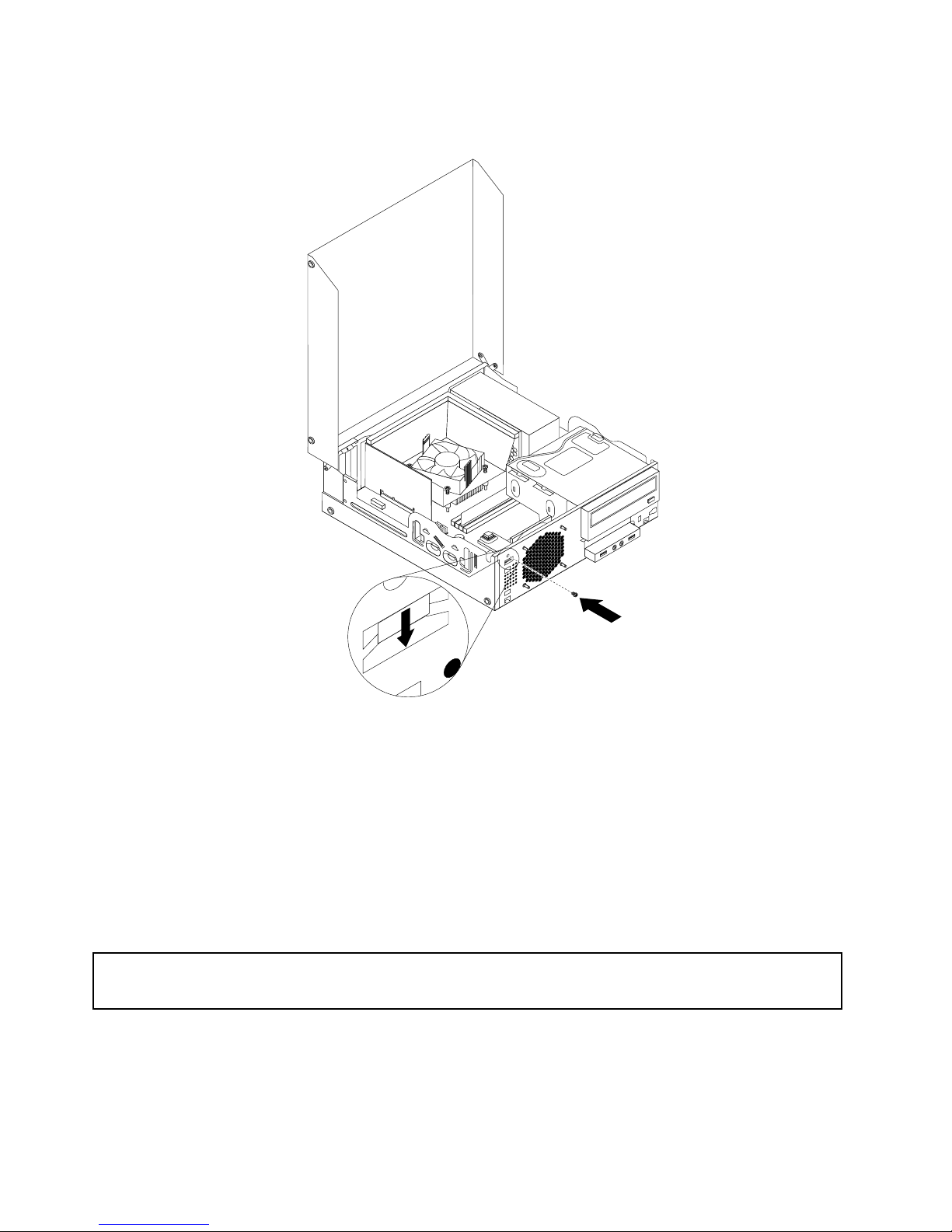
8.Installthescrewtosecurethecoverpresenceswitchtothechassis.
Figure58.Installingthenewcoverpresenceswitch
9.Reconnectthecoverpresenceswitchcabletothesystemboard.See“Locatingpartsonthesystem
board”onpage11
.
10.Reinstallthefrontbezel.See“Removingandreinstallingthefrontbezel”onpage32.
Whattodonext:
•Toworkwithanotherpieceofhardware,gototheappropriatesection.
•Tocompletetheinstallationorreplacement,goto“Completingthepartsreplacement”onpage87.
Replacingtheinternalspeaker
Attention:
Donotopenyourcomputerorattemptanyrepairbeforereadingandunderstandingthe“Importantsafetyinformation”
onpagev
.
Thissectionprovidesinstructionsonhowtoreplacetheinternalspeaker.
Note:Theinternalspeakerisonlyavailableinsomemodels.
Toreplacetheinternalspeaker,dothefollowing:
72ThinkCentreUserGuide
Page 85

1.T urnoffthecomputeranddisconnectallpowercordsfromelectricaloutlets.
2.Openthecomputercover.See“Openingthecomputercover”onpage32.
3.Removethefrontbezel.See“Removingandreinstallingthefrontbezel”onpage32.
4.Locatetheinternalspeaker.See“Locatingcomponents”onpage11.
5.Disconnecttheinternalspeakercablefromtheinternalspeakerconnectoronthesystemboard.See
“Locatingpartsonthesystemboard”onpage11.
6.Removethecoverpresenceswitch(intrusionswitch).See“Replacingthecoverpresenceswitch”
onpage70.
7.Pushtheinternalspeakeroutwardthroughthehole1todisengageitfromthetwometaltabsonthe
chassis.Then,slidetheinternalspeakertotherighttoremoveitfromthechassis.
Figure59.Removingtheinternalspeaker
8.Alignthenewinternalspeakerwiththetwometalclipsonthechassis,andthenslidethespeaker
asshownuntilitsnapsintoposition.
Chapter5.Installingorreplacinghardware73
Page 86

Figure60.Installingthenewinternalspeaker
9.Reconnecttheinternalspeakercabletothesystemboard.See“Locatingpartsonthesystemboard”
onpage11.
10.Reinstallthecoverpresenceswitch.See“Replacingthecoverpresenceswitch”onpage70.
11.Reinstallthefrontbezel.See“Removingandreinstallingthefrontbezel”onpage32.
Whattodonext:
•Toworkwithanotherpieceofhardware,gototheappropriatesection.
•Tocompletetheinstallationorreplacement,goto“Completingthepartsreplacement”onpage87.
ReplacingthefrontaudioandUSBassembly
Attention:
Donotopenyourcomputerorattemptanyrepairbeforereadingandunderstandingthe“Importantsafetyinformation”
onpagev.
ThissectionprovidesinstructionsonhowtoreplacethefrontaudioandUSBassembly.
ToreplacethefrontaudioandUSBassembly,dothefollowing:
74ThinkCentreUserGuide
Page 87

1.Removeallmediafromthedrivesandturnoffallattacheddevicesandthecomputer.Then,disconnect
allpowercordsfromelectricaloutletsanddisconnectallcablesthatareconnectedtothecomputer.
2.Openthecomputercover.See“Openingthecomputercover”onpage32.
3.Removethefrontbezel.See“Removingandreinstallingthefrontbezel”onpage32.
4.PivottheopticaldrivebayupwardanddisconnectthefrontaudioandUSBassemblycablesfromthe
systemboardandnotethecablesrouting.See“Locatingpartsonthesystemboard”onpage11.
5.RemovethescrewthatsecuresthefrontaudioandUSBassemblybracket.Thenremovethefront
audioandUSBassemblybracketfromthechassis.
Figure61.RemovingthefrontaudioandUSBassembly
6.RemovethetwoscrewsthatsecurethefrontaudioandUSBassemblytoitsbracket.Thenremovethe
failingfrontaudioandUSBassemblyfromthebracket.
7.InstallanewfrontaudioandUSBassemblyintothebracketandinstallthetwoscrewstosecurethe
frontaudioandUSBassemblytothebracket.
8.InstallthefrontaudioandUSBassemblybrackettothechassisandalignthescrewholeinthebracket
withthecorrespondingholeinthechassis.
9.InstallthescrewtosecurethefrontaudioandUSBassemblybrackettothechassis.
10.ReconnectthefrontUSBandfrontaudiocablestothesystemboard.See“Locatingpartsonthe
systemboard”onpage11.
11.Reinstallthefrontbezel.See“Removingandreinstallingthefrontbezel”onpage32.
Whattodonext:
•Toworkwithanotherpieceofhardware,gototheappropriatesection.
•Tocompletetheinstallationorreplacement,goto“Completingthepartsreplacement”onpage87
.
Chapter5.Installingorreplacinghardware75
Page 88

Replacingthesystemfanassembly
Attention:
Donotopenyourcomputerorattemptanyrepairbeforereadingandunderstandingthe“Importantsafetyinformation”
onpagev
.
Thissectionprovidesinstructionsonhowtoreplacethesystemfanassembly.
Toreplacethesystemfanassembly,dothefollowing:
1.Removeallmediafromthedrivesandturnoffallattacheddevicesandthecomputer.Then,disconnect
allpowercordsfromelectricaloutletsanddisconnectallcablesthatareconnectedtothecomputer.
2.Openthecomputercover.See“Openingthecomputercover”onpage32.
3.Removethefrontbezel.See“Removingandreinstallingthefrontbezel”onpage32.
4.Locatethesystemfanassembly.See“Locatingcomponents”onpage11.
5.Removetheharddiskdrive.See“Replacingtheharddiskdrive”onpage54.
6.Pivottheopticaldrivebayupwardandthenremovetheheatsinkfanductforeasieraccesstothe
systemfanassemblycable.See“Replacingtheheatsinkandfanassembly”onpage59.
7.Disconnectthesystemfanassemblycablefromthesystemfanconnectoronthesystemboard.See
“Locatingpartsonthesystemboard”onpage11.
8.Thesystemfanassemblyisattachedtothechassisbyfourrubbermounts.Removethesystemfan
assemblybybreakingorcuttingtherubbermountsandgentlypullingthesystemfanassemblyoutof
thechassis.
Note:Thenewsystemfanassemblywillhavefournewrubbermountsattached.
Figure62.Removingthesystemfanassembly
9.Installthenewsystemfanassemblybyaligningthenewrubbermountswiththecorrespondingholesin
thechassisandpushtherubbermountsthroughtheholes.
76ThinkCentreUserGuide
Page 89

10.Pullthetipsoftherubbermountsuntilthesystemfanassemblyissecuredinplace.
Figure63.Installingthesystemfanassembly
11.Connectthesystemfanassemblycabletothesystemfanconnectoronthesystemboard.See
“Locatingpartsonthesystemboard”onpage11.
12.Pivottheopticaldrivebaydownward.Reinstalltheheatsinkfanduct.See“Replacingtheheatsinkand
fanassembly”onpage59.
13.Reinstalltheharddiskdrive.See“Replacingtheharddiskdrive”onpage54.
14.Reinstallthefrontbezel.See“Removingandreinstallingthefrontbezel”onpage32.
Whattodonext:
•Toworkwithanotherpieceofhardware,gototheappropriatesection.
•Tocompletetheinstallationorreplacement,goto“Completingthepartsreplacement”onpage87.
ReplacingtheWiFiunits
Attention:
Donotopenyourcomputerorattemptanyrepairbeforereadingandunderstandingthe“Importantsafetyinformation”
onpagev.
Chapter5.Installingorreplacinghardware77
Page 90

ThissectionprovidesinstructionsonhowtoreplacetheWiFiunits.TheWiFiunitsincludeaWiFiadapter
card,aWiFicardmodule,andarearWiFiantennacable.
ReplacingtheWiFiunitsinvolvesthefollowingoperations:
•“RemovingtheWiFiadaptercard”onpage78
•“RemovingtheWiFicardmodule”onpage79
•“InstallingtheWiFiunits”onpage80
RemovingtheWiFiadaptercard
ToremovetheWiFiadaptercard,dothefollowing:
1.T urnoffthecomputeranddisconnectallpowercordsfromelectricaloutlets.
2.Openthecomputercover.See“Openingthecomputercover”onpage32.
3.IfyourcomputercomeswithaWiFicardmodulethatsupportstheBluetoothfunction,disconnect
theBluetoothcablefromtheWiFiadaptercard.
Figure64.DisconnectingtheBluetoothcable
Note:TheBluetoothcableconnectstheBluetoothconnectorontheWiFiadaptercardtothefrontUSB
connectoronthesystemboardtosupporttheBluetoothfunction.
4.RotatethePCIcardretainertotheopenposition.
78ThinkCentreUserGuide
Page 91

5.GrasptheWiFiadaptercardthatiscurrentlyinstalledandgentlypullitoutoftheslot.
Figure65.RemovingtheWiFiadaptercard
Note:Thecardtstightlyintothecardslot.Ifnecessary,alternatemovingeachsideofthecarda
smallamountuntilitisremovedfromthecardslot.
RemovingtheWiFicardmodule
ToremovetheWiFicardmodule,dothefollowing:
1.RemovetheWiFiadaptercardfromthecomputer,andthendisconnectthefrontandrearWiFiantenna
cablesfromtheWiFicardmodule.
Figure66.RemovingtheWiFiantennacables
Chapter5.Installingorreplacinghardware79
Page 92
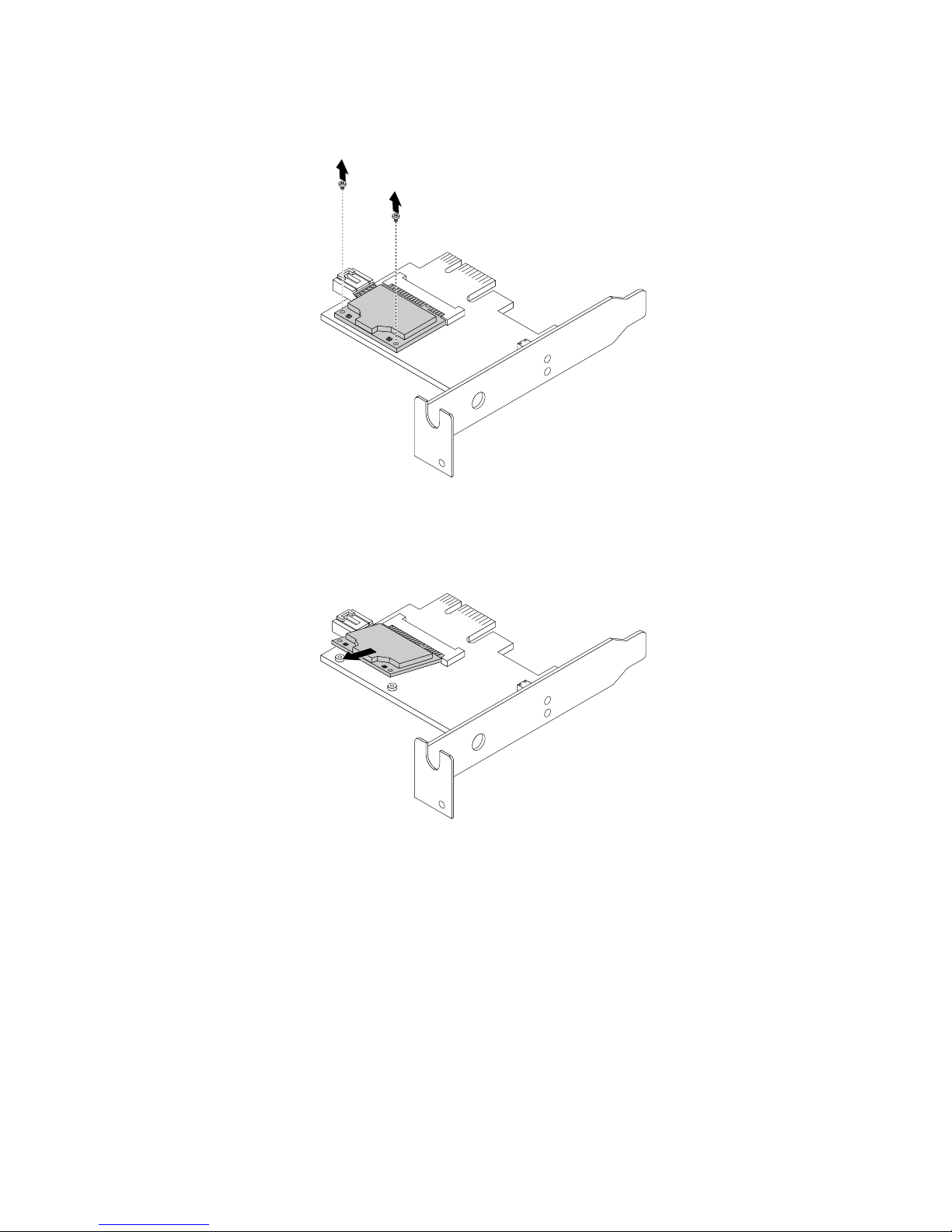
2.RemovethetwoscrewsthatsecuretheWiFicardmoduletotheWiFiadaptercard.
Figure67.RemovingthescrewsthatsecuretheWiFicardmodule
3.PulltheWiFicardmoduleoutoftheminiPCIExpressslottoremoveitfromtheWiFiadaptercard.
Figure68.RemovingtheWiFicardmodule
InstallingtheWiFiunits
ToinstalltheWiFiunits,dothefollowing:
80ThinkCentreUserGuide
Page 93

1.InserttheWiFicardmoduleintotheminiPCIExpressslot,andtheninstallthetwoscrewstosecure
theWiFicardmoduletotheWiFiadaptercard.
Figure69.InstallingtheWiFicardmodule
2.ConnectthefrontantennacableandrearantennacabletotheWiFicardmodule.
Figure70.ConnectingtheWiFiantennacables
Chapter5.Installingorreplacinghardware81
Page 94

3.InstalltheWiFiadaptercardintothePCIExpressx1slotonthesystemboard.See“Locatingpartson
thesystemboard”onpage11.
4.IftheinstalledWiFicardmodulesupportstheBluetoothfunction,useaBluetoothcabletoconnectthe
BluetoothconnectorontheWiFiadaptercardtothefrontUSBconnectoronthesystemboard.
5.PivotthecardlatchtotheclosedpositiontosecuretheWiFiadaptercard.
Figure71.InstallingtheWiFiadaptercard
Whattodonext:
•Toworkwithanotherpieceofhardware,gototheappropriatesection.
•Tocompletetheinstallationorreplacement,goto“Completingthepartsreplacement”onpage87.
InstallingorremovingtherearWiFiantenna
Attention:
Donotopenyourcomputerorattemptanyrepairbeforereadingandunderstandingthe“Importantsafetyinformation”
onpagev.
ThissectionprovidesinstructionsonhowtoinstallorremovetherearWiFiantenna.
InstallingtherearWiFiantenna
ToinstalltherearWiFiantenna,dothefollowing:
1.T urnoffthecomputeranddisconnectallpowercordsfromelectricaloutlets.
2.InstalltherearWiFiantennatotherearWiFiantennacableconnectorattachedontherearofthe
computer.
3.Adjusttheangleoftherearantennatolowertheriskofbreakingtheantennabyaccident.
82ThinkCentreUserGuide
Page 95

Figure72.InstallingtherearWiFiantenna
Whattodonext:
•Toworkwithanotherpieceofhardware,gototheappropriatesection.
•Tocompletetheinstallationorreplacement,goto“Completingthepartsreplacement”onpage87
.
RemovingtherearWiFiantenna
ToremovetherearWiFiantenna,dothefollowing:
1.T urnoffthecomputeranddisconnectallpowercordsfromelectricaloutlets.
2.StraightentherearWiFiantennasothatitcanbemoreeasilytwisted.
Chapter5.Installingorreplacinghardware83
Page 96

3.HoldthethickerendoftherearWiFiantennaandunscrewtheWiFiantennafromtherearofthe
computer.
Figure73.RemovingtherearWiFiantenna
Whattodonext:
•Toworkwithanotherpieceofhardware,gototheappropriatesection.
•Tocompletetheinstallationorreplacement,goto“Completingthepartsreplacement”onpage87.
InstallingorremovingthefrontWiFiantenna
Attention:
Donotopenyourcomputerorattemptanyrepairbeforereadingandunderstandingthe“Importantsafetyinformation”
onpagev
.
ThissectionprovidesinstructionsonhowtoinstallorremovethefrontWiFiantenna.
InstallingthefrontWiFiantenna
ToinstallthefrontWiFiantenna,dothefollowing:
1.T urnoffthecomputeranddisconnectallpowercordsfromelectricaloutlets.
2.Openthecomputercover.See“Openingthecomputercover”onpage32.
3.Removethefrontbezel.See“Removingandreinstallingthefrontbezel”onpage32.
4.Removetheharddiskdrive.See“Replacingtheharddiskdrive”onpage54.
5.Peeloffthepaperthatprotectsthestickeronthefrontantenna.
84ThinkCentreUserGuide
Page 97

Figure74.Peelingoffthepaperthatprotectsthesticker
6.Stickthefrontantennatothefrontpanelasshown.Theninsertthefrontantennacablethroughthe
holeinthefrontpanel.
Figure75.InstallingthefrontWiFiantenna
Chapter5.Installingorreplacinghardware85
Page 98

7.ConnectthefrontantennacabletotheWiFicardmodule.
8.Reinstalltheharddiskdrive.See“Replacingtheharddiskdrive”onpage54.
Whattodonext:
•Toworkwithanotherpieceofhardware,gototheappropriatesection.
•Tocompletetheinstallationorreplacement,goto“Completingthepartsreplacement”onpage87
.
RemovingthefrontWiFiantenna
ToremovethefrontWiFiantenna,dothefollowing:
1.T urnoffthecomputeranddisconnectallpowercordsfromelectricaloutlets.
2.Openthecomputercover.See“Openingthecomputercover”onpage32.
3.Removethefrontbezel.See“Removingandreinstallingthefrontbezel”onpage32.
4.Removetheharddiskdrive.See“Replacingtheharddiskdrive”onpage54.
5.DisconnectthefrontantennacablefromtheWiFicardmodule.
6.Removethefrontantennaandcablefromthefrontofthecomputer.
Figure76.RemovingthefrontWiFiantenna
Whattodonext:
•Toworkwithanotherpieceofhardware,gototheappropriatesection.
•Tocompletetheinstallationorreplacement,goto“Completingthepartsreplacement”onpage87.
86ThinkCentreUserGuide
Page 99
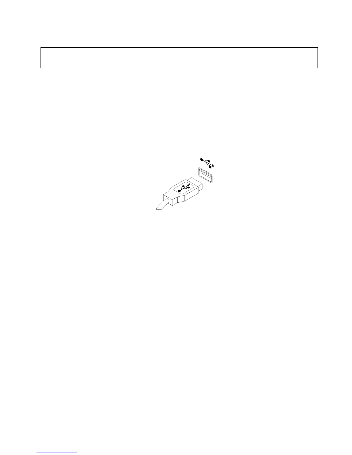
Replacingthekeyboardormouse
Attention:
Donotopenyourcomputerorattemptanyrepairbeforereadingandunderstandingthe“Importantsafetyinformation”
onpagev
.
Thissectionprovidesinstructionsonhowtoreplacethekeyboardormouse.
Toreplacethekeyboardormouse,dothefollowing:
1.Removeanymediafromthedrives.Then,turnoffallattacheddevicesandthecomputer.
2.Disconnectallpowercordsfromelectricaloutlets.
3.Disconnecttheoldkeyboardcableormousecablefromthecomputer.
4.ConnectanewkeyboardormousetooneoftheUSBconnectorsonthecomputer.Dependingonwhere
youwanttoconnectthenewkeyboardormouse,see“Locatingconnectors,controls,andindicatorson
thefrontofyourcomputer”onpage8or“Locatingconnectorsontherearofyourcomputer”onpage9.
Figure77.Connectinganewkeyboardormouse
Whattodonext:
•Toworkwithanotherpieceofhardware,gototheappropriatesection.
•Tocompletetheinstallationorreplacement,goto“Completingthepartsreplacement”onpage87.
Completingthepartsreplacement
Aftercompletingtheinstallationorreplacementforallparts,youneedtoclosethecomputercoverand
reconnectcables.Dependingonthepartsyouinstalledorreplaced,youmightneedtoconrmtheupdated
informationintheSetupUtilityprogram.RefertoChapter7“UsingtheSetupUtilityprogram”onpage97.
Toclosethecomputercoverandreconnectcablestoyourcomputer,dothefollowing:
1.Ensurethatallcomponentshavebeenreassembledcorrectlyandthatnotoolsorloosescrewsareleft
insideyourcomputer.See“Locatingcomponents”onpage11
forthelocationsofvariouscomponents
inyourcomputer.
2.Ifyouhaveremovedthefrontbezel,reinstallit.T oreinstallthefrontbezel,alignthethreetabson
thefrontbezelwiththecorrespondingholesinthechassisandpivotthefrontbezelinwardsuntil
itsnapsintoposition.
3.Ensurethatthecablesareroutedcorrectly.Keepcablesclearofthehingesandsidesofthecomputer
chassistoavoidinterferencewithclosingthecomputercover.
4.Lowertheopticaldrivebay.
5.Closethecomputercover.
6.Ifthereisanintegratedcablelockavailable,lockthecomputer.
7.Reconnecttheexternalcablesandpowercordstothecomputer.See“Locatingconnectorsontherear
ofyourcomputer”onpage9.
Chapter5.Installingorreplacinghardware87
Page 100

8.T oupdateyourconguration,seeChapter7“UsingtheSetupUtilityprogram”onpage97.
Note:Inmostareasoftheworld,LenovorequiresthereturnofthedefectiveCustomerReplaceableUnit
(CRU).InformationaboutthiswillcomewiththeCRUorwillcomeafewdaysaftertheCRUarrives.
Obtainingdevicedrivers
Youcanobtaindevicedriversforoperatingsystemsthatarenotpreinstalledat
http://www.lenovo.com/support.Installationinstructionsareprovidedinreadmeleswiththedevice-driver
les.
88ThinkCentreUserGuide
 Loading...