


M70a and M90a
User Guide

Read this first
Before using this documentation and the product it supports, ensure that you read and understand the
following:
• Appendix A “Important safety information” on page 83
• Safety and Warranty Guide
• Setup Guide
First Edition (April 2020)
© Copyright Lenovo 2020.
LIMITED AND RESTRICTED RIGHTS NOTICE: If data or software is delivered pursuant to a General Services
Administration “GSA” contract, use, reproduction, or disclosure is subject to restrictions set forth in Contract No. GS35F-05925.

Contents
About this documentation . . . . . . . . iii
Chapter 1. Meet your computer. . . . . 1
Front . . . . . . . . . . . . . . . . . . . . 1
Rear . . . . . . . . . . . . . . . . . . . . 3
Locating connectors on system board . . . . . . . 4
Features and specifications . . . . . . . . . . . 6
Statement on USB transfer rate . . . . . . . . 7
Chapter 2. Get started with your
computer . . . . . . . . . . . . . . . . . 9
Adjust the computer stand (for selected models) . . . 9
Get started with Windows 10 . . . . . . . . . 10
Windows account . . . . . . . . . . . . 10
Windows user interface . . . . . . . . . . 11
Connect to networks. . . . . . . . . . . . . 12
Connect to the wired Ethernet . . . . . . . 12
Connect to Wi-Fi networks (for selected
models) . . . . . . . . . . . . . . . . 12
Use Lenovo Vantage . . . . . . . . . . . . . 12
Use Night light . . . . . . . . . . . . . . . 13
Use the multi-touch screen (for selected
models) . . . . . . . . . . . . . . . . . . 13
Use multimedia . . . . . . . . . . . . . . . 16
Use audio . . . . . . . . . . . . . . . 16
Use the camera (for selected models) . . . . 16
Connect to an external display . . . . . . . 16
Chapter 3. Explore your computer . . 19
Manage power . . . . . . . . . . . . . . . 19
Set power button behaviors . . . . . . . . 19
Set the power plan . . . . . . . . . . . . 19
Transfer data . . . . . . . . . . . . . . . . 19
Connect to a Bluetooth-enabled device (for
selected models) . . . . . . . . . . . . 19
Use the optical drive (for selected models) . . 20
Use a media card (for selected models). . . . 20
Purchase accessories . . . . . . . . . . . . 21
Chapter 4. Secure your computer
and information . . . . . . . . . . . . 23
Lock the computer . . . . . . . . . . . . . 23
Log in to your computer securely . . . . . . . . 23
Use passwords . . . . . . . . . . . . . 23
Use face authentication (for selected
models) . . . . . . . . . . . . . . . . 24
Use software security solutions. . . . . . . . . 25
Use firewalls . . . . . . . . . . . . . . 25
Use antivirus programs . . . . . . . . . . 25
Use computrace Agent software embedded in
firmware (for selected models) . . . . . . . 25
Use BIOS security solutions . . . . . . . . . . 25
Erase all storage drive data . . . . . . . . 26
Use the cover presence switch . . . . . . . 26
Use Intel BIOS guard . . . . . . . . . . . 26
Use Smart USB Protection. . . . . . . . . 26
Chapter 5. UEFI BIOS . . . . . . . . . 29
What is UEFI BIOS. . . . . . . . . . . . . . 29
Enter the BIOS menu. . . . . . . . . . . . . 29
Navigate in the BIOS interface . . . . . . . . . 29
Change the display language of UEFI BIOS . . . . 29
Set the system date and time . . . . . . . . . 30
Change the startup sequence . . . . . . . . . 30
Enable or disable the configuration change
detection feature . . . . . . . . . . . . . . 30
Enable or disable the automatic power-on
feature . . . . . . . . . . . . . . . . . . 31
Enable or disable the smart power-on feature . . . 31
Enable or disable the ErP LPS compliance mode . . 31
Change the ICE performance mode . . . . . . . 32
Change BIOS settings before installing a new
operating system . . . . . . . . . . . . . . 32
Update UEFI BIOS. . . . . . . . . . . . . . 32
Recover from a BIOS update failure . . . . . . . 33
Clear CMOS . . . . . . . . . . . . . . . . 34
Chapter 6. Troubleshooting,
diagnostics, and recovery . . . . . . . 35
Basic procedure for resolving computer
problems . . . . . . . . . . . . . . . . . 35
Troubleshooting . . . . . . . . . . . . . . 35
Startup problems . . . . . . . . . . . . 36
Screen problems . . . . . . . . . . . . 37
Audio problems . . . . . . . . . . . . . 38
Network problems . . . . . . . . . . . . 38
Performance problems . . . . . . . . . . 41
Storage drive problems . . . . . . . . . . 42
CD or DVD problems . . . . . . . . . . . 42
Serial connector problems. . . . . . . . . 43
USB device problems . . . . . . . . . . 43
Software problems. . . . . . . . . . . . 44
Diagnostics . . . . . . . . . . . . . . . . 44
Lenovo diagnostic tools. . . . . . . . . . 44
Recovery . . . . . . . . . . . . . . . . . 44
© Copyright Lenovo 2020 i

Restore system files and settings to an earlier
point . . . . . . . . . . . . . . . . . 44
Restore your files from a backup . . . . . . 44
Reset your computer . . . . . . . . . . . 44
Use advanced options . . . . . . . . . . 45
Windows automatic recovery. . . . . . . . 45
Create and use a recovery USB device . . . . 45
Update the device driver . . . . . . . . . 46
Chapter 7. CRU replacement . . . . . 47
What are CRUs . . . . . . . . . . . . . . . 47
Replace a CRU . . . . . . . . . . . . . . . 48
Computer stand . . . . . . . . . . . . . 48
Rear cover . . . . . . . . . . . . . . . 52
Optical drive . . . . . . . . . . . . . . 53
Optical drive holder . . . . . . . . . . . 56
System board shield . . . . . . . . . . . 58
VESA mount bracket cover . . . . . . . . 61
VESA mount bracket . . . . . . . . . . . 63
Storage drive and storage drive bracket . . . 65
M.2 solid-state drive . . . . . . . . . . . 70
Memory module . . . . . . . . . . . . . 74
Chapter 8. Help and support . . . . . 79
Self-help resources . . . . . . . . . . . . . 79
Call Lenovo . . . . . . . . . . . . . . . . 80
Before you contact Lenovo . . . . . . . . 80
Lenovo Customer Support Center . . . . . . 80
Purchase additional services. . . . . . . . . . 81
Appendix A. Important safety
information . . . . . . . . . . . . . . . 83
Appendix B. Accessibility and
ergonomic information . . . . . . . . 97
Appendix C. Supplemental
information about the Ubuntu operating
system . . . . . . . . . . . . . . . . . 101
Appendix D. Compliance
information . . . . . . . . . . . . . . . 103
Appendix E. Notices and
trademarks . . . . . . . . . . . . . . . 113
ii M70a and M90a User Guide

About this documentation
• Illustrations in this documentation might look different from your product.
• Depending on the model, some optional accessories, features, and software programs might not be
available on your computer.
• Depending on the version of operating systems and programs, some user interface instructions might not
be applicable to your computer.
• Documentation content is subject to change without notice. Lenovo makes constant improvements on the
documentation of your computer, including this User Guide. To get the latest documentation, go to:
https://pcsupport.lenovo.com
• Microsoft® makes periodic feature changes to the Windows® operating system through Windows Update.
As a result, some information in this documentation might become outdated. Refer to Microsoft resources
for the latest information.
© Copyright Lenovo 2020 iii

iv M70a and M90a User Guide
Chapter 1. Meet your computer
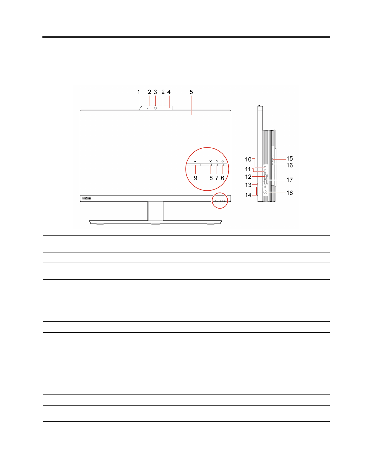
Front
1. Integrated camera activity
indicator*
2. Microphones* Capture or record sound and voice.
3. Integrated camera or IR
camera shield*
4. Integrated camera or IR
camera*
5. Multi-touch screen*
6. System status indicator
7. Storage drive activity indicator This indicator is on when the storage drive is in use.
8. Microphone mute/unmute
indicator*
This indicator is on when the camera is in use.
Slide to cover the camera lens whenever you need.
• Take pictures or record videos by clicking Camera from the Start menu.
• Log in to your computer with face authentication.
If you use other apps that support photographing, video chatting, and video
conference, the camera starts automatically when you enable the camerarequired feature from the app.
Enable you to use your computer with simple touch gestures.
The indicator shows the system status of your computer.
• Blinking for three times: The computer is initially connected to power.
• On: The computer is on.
• Off: The computer is off or in hibernation mode.
• Blinking rapidly: The computer is entering hibernation mode.
• Breathing (blinking slowly): The computer is in sleep or modern standby
mode.
This indicator is on when the microphones are muted.
© Copyright Lenovo 2020 1

9. E-Privacy button*
Press the button to enable the E-Privacy mode. In this mode, your screen
prevents visual hackers from stealing sideways glances at your screen, while
providing a crisp, clear view for intended users. To exit from the mode, press the
button again.
10. Microphone mute/unmute
control*
11. USB-C
™
connector (USB 3.2
Gen 1)
12. USB 3.2 connector Gen 2
13. USB 3.2 connectors Gen 2
(M90a) or USB 3.2 connector
Gen 1 (M70a)
14. Headset connector
15. Optical drive eject/close
button*
16. Optical drive activity
indicator*
17. SD-card slot*
Mute or unmute the integrated microphones in the computer mode.
• Charge USB-C compatible devices with the output voltage and current of 5 V
and 3 A.
• Transfer data at USB 3.2 speed, up to 5 Gbps.
• Connect to USB-C accessories to help expand your computer functionality. To
purchase USB-C accessories, go to
https://www.lenovo.com/accessories.
Connect USB-compatible devices, such as a USB keyboard, USB mouse, USB
storage device, or USB printer.
Connect USB-compatible devices, such as a USB keyboard, USB mouse, USB
storage device, or USB printer.
Connect a headset or headphones to your computer.
Eject or close the optical drive tray.
This indicator is on when the optical drive is in use.
Supported cards:
• Secure Digital (SD) card
• Secure Digital eXtended-Capacity (SDXC) UHS-1 card
• Secure Digital High-Capacity (SDHC) UHS-1 card
18. Power button
* for selected models
Note: Your computer does not support the content protection for recordable
media (CPRM) feature for the SD card.
Press to turn on the computer.
To turn off the computer, open the Start menu, click
Power, and then select
Shut down.
2
M70a and M90a User Guide
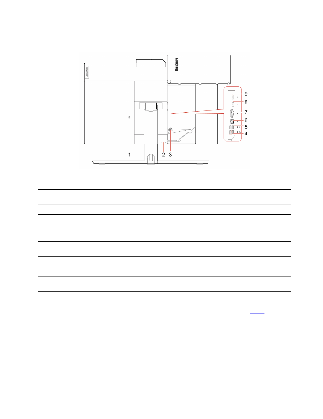
Rear
1. Security-lock slot
2. Cable cover eject button
3. Cable clip Press the clip to route the cables connected to the computer.
4. USB 3.2 connector Gen 1 (with
keyboard smart power on
feature)
5. USB 3.2 connectors Gen 1 (3)
6. Ethernet connector
7. Serial connector*
8. Power cord connector
9. DisplayPort
®
1.2 out connector
Lock your computer to a desk, table, or other fixtures through a Kensington-style
cable lock.
Press the button to access the covered connectors and cables.
Note: For easy access, do not cover the button with any external parts.
Connect USB-compatible devices, such as a USB keyboard, USB mouse, USB
storage device, or USB printer.
Note: When a USB keyboard is connected, you can turn on the computer by
pressing Alt+P on the keyboard.
Connect USB-compatible devices, such as a USB keyboard, USB mouse, USB
storage device, or USB printer.
Connect to a local area network (LAN). When the green indicator is on, the
computer is connected to a LAN. When the yellow indicator blinks, data is being
transmitted.
Connect an external modem, a serial printer, or other devices that use a serial
connector.
Connect the power cord to your computer for power supply.
Send audio and video signals from the computer to another audio or video device,
such as a high-performance monitor. For more information, see
www.vesa.org/wp-content/uploads/2010/12/DisplayPort-DevCon-Presentation-DP-
1.2-Dec-2010-rev-2b.pdf
.
https://
* for selected models
Chapter 1. Meet your computer 3
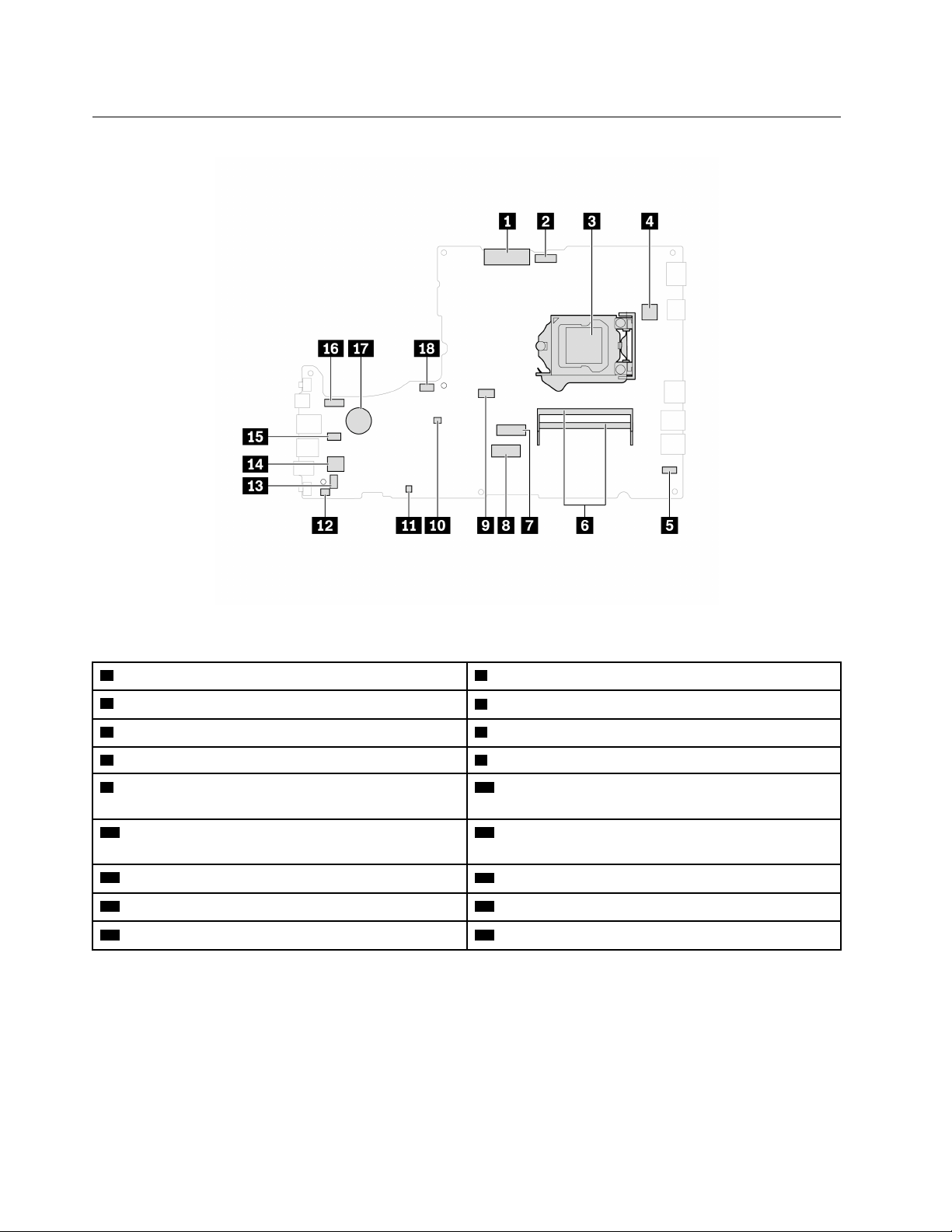
Locating connectors on system board
Figure 1. M70a system board
1 LCD LVDS connector
3 Microprocessor socket
5 Touch board connector 6 Memory slots
7 M.2 solid-state drive slot 8 M.2 Wi-Fi card slot
9 Optical drive connector 10 Clear CMOS (Complementary Metal Oxide
2 Integrated camera and microphone module connector
4 Serial (COM1) connector
Semiconductor) / Recovery jumper
11 ME disable header
12 Cover presence switch connector (intrusion switch
connector)
13 Internal speaker connector
15 Card reader connector 16 LCD backlight connector
17 Coin-cell battery 18 System fan connector
14 Storage drive connector
4 M70a and M90a User Guide
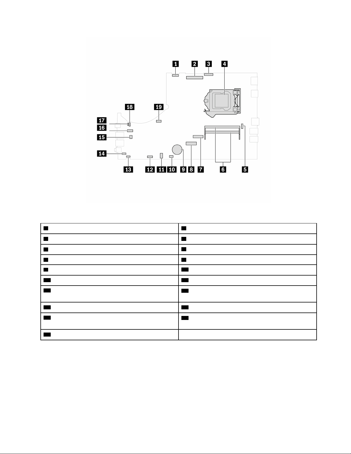
Figure 2. M90a system board
1 LCD backlight connector 2 LCD LVDS connector
3 Integrated camera and microphone module connector 4 Microprocessor socket
5 Serial (COM1) connector
7 M.2 solid-state drive slot 8 M.2 Wi-Fi card slot
9 Coin-cell battery
11 Optical drive connector
13 E-Privacy connector
6 Memory slots
10 Touch board connector
12 Internal speaker connector
14 Cover presence switch connector (intrusion switch
connector)
15 Card reader connector 16 Storage drive connector
17 ME disable header
18 Clear CMOS (Complementary Metal Oxide
Semiconductor) / Recovery jumper
19 System fan connector
Chapter 1. Meet your computer 5

Features and specifications
• M70a:
– Width: 490.1 mm (19.3 inches)
– Height: 312.3 mm (12.3 inches)
– Depth: 55.6 mm (2.2 inches)
• M90a:
Dimensions (without any
computer stand)
Weight (without the package)
Hardware configuration
– E-Privacy models:
– Width: 541 mm(21.3 inches)
– Height: 338.5 mm (13.3 inches)
– Depth: 49.5 mm (2.4 inches)
– Non E-Privacy models:
– Width: 541 mm(21.3 inches)
– Height: 338.5 mm (13.3 inches)
– Depth: 57.8 mm (2.3 inches)
Maximum configuration as shipped:
• M70a: 8.1 kg (17.9 lb)
• M90a: 9.1 kg (20.1 lb)
1. Right-click the Start button to open the Start context menu.
2. Click Device Manager. Type the administrator password or provide
confirmation if prompted.
• 135-watt automatic voltage-sensing power supply
Power supply
Electrical input
Microprocessor
Memory Double data rate 4 (DDR4) small outline dual in-line memory module (SODIMM)
Storage device
• 150-watt automatic voltage-sensing power supply
• 170-watt automatic voltage-sensing power supply
• 230-watt automatic voltage-sensing power supply
• Input voltage: From 100 V ac to 240 V ac
• Input frequency: 50/60 Hz
To view the microprocessor information of your computer, right-click the Start
button and then click System.
• 2.5-inch form factor, 7-mm (0.28-inch) height storage drive*
• M.2 solid-state drive*
®
• Intel
To view the storage drive capacity of your computer, right-click the Start button
to open the Start context menu and then click Disk Management.
Note: The storage drive capacity indicated by the system is less than the nominal
capacity.
Optane™ memory*
6 M70a and M90a User Guide

Video features
Audio features
Expansion
• Color display with White Light Emitting Diode (WLED) technology
• Color display with Full High Definition (FHD) technology
• Display size:
– M70a: 546.1 mm (21.5 inches)
– M90a: 604.5 mm (23.8 inches)
• Display resolution: 1920 x 1080 pixels
• Multi-touch technology*
• The integrated graphics card supports DisplayPort 1.2 out connector.
• The optional discrete graphics card provides an enhanced video experience
and extended capabilities.
• The integrated audio card supports the following:
– Headset connector
– Integrated microphones*
– Internal speakers
• Card reader*
• Memory slots
• M.2 solid-state drive slot
• Optical drive*
• Storage drive bay
• Bluetooth*
Network features
• Ethernet LAN
• Wireless LAN*
* for selected models
Statement on USB transfer rate
Depending on many factors such as the processing capability of the host and peripheral devices, file
attributes, and other factors related to system configuration and operating environments, the actual transfer
rate using the various USB connectors on this device will vary and will be slower than the data rate listed
below for each corresponding device.
USB device Data rate (Gbit/s)
3.2 Gen 1 / 3.1 Gen 1
3.2 Gen 2 / 3.1 Gen 2
3.2 Gen 2 × 2
5
10
20
Chapter 1. Meet your computer 7

8 M70a and M90a User Guide
Chapter 2. Get started with your computer
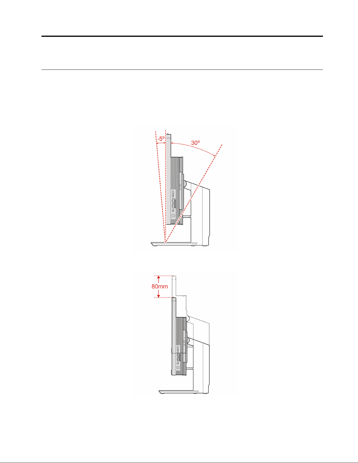
Adjust the computer stand (for selected models)
Note: For information about installing the computer stand, refer to the setup guide that comes with your
computer.
Full-function monitor stand
• Tilt the screen forward and back.
• Adjust the height of the screen.
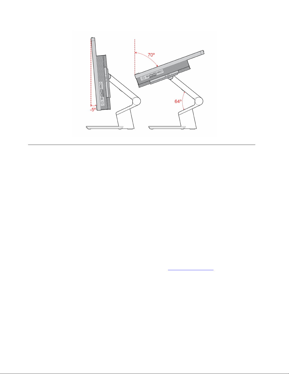
UltraFlex IV Stand
• Tilt the screen forward and back.
© Copyright Lenovo 2020 9
Get started with Windows 10
Learn the basics of Windows 10 and start working with it right away. For more information about Windows
10, see the Windows help information.
Windows account
A user account is required to use the Windows operating system. It can either be a Windows user account or
a Microsoft account.
Windows user account
When you start Windows for the first time, you are prompted to create a Windows user account. This first
account you created is of the “Administrator” type. With an Administrator account, you can create additional
user accounts or change account types by doing the following:
1. Open the Start menu and select Settings ➙ Accounts ➙ Family & other users.
2. Follow the on-screen instructions.
Microsoft account
You can also log in to the Windows operating system with a Microsoft account.
To create a Microsoft account, go to the Microsoft sign-up page at
screen instructions.
With a Microsoft account, you can:
• Enjoy one-time signing in if you are using other Microsoft services, such as OneDrive, Skype, and Outlook.
com.
• Sync personalized settings across other Windows-based devices.
10
M70a and M90a User Guide
https://signup.live.com and follow the on-
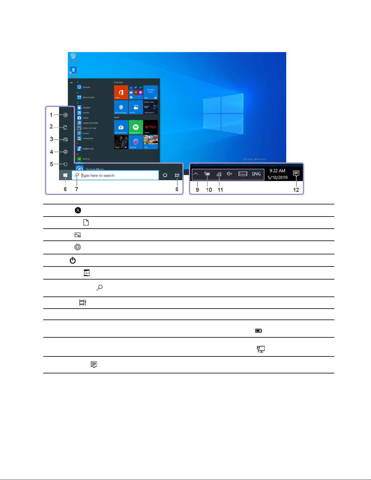
Windows user interface
1. Account
2. Documents
3. Pictures
4. Settings
5. Power
6. Start button
7. Windows Search
8. Task View
9. Windows notification area
10. Battery status icon
11. Network icon
12. Action center
Change account settings, lock the computer, or sign out from the current account.
Open the Documents folder, a default folder to save your received files.
Open the Pictures folder, a default folder to save your received pictures.
Launch Settings.
Shut down, restart, or put the computer into sleep mode.
Open the Start menu.
Type what you are looking for in the search box and get search results from your
computer and the Web.
Display all opened apps and switch among them.
Display notifications and status of some features.
Display power status and change battery or power settings. When your computer
is not connected to ac power, the icon changes to
Connect to an available wireless network and display the network status. When
connected to a wired network, the icon changes to
Display the latest notifications from apps and provide quick access to some
features.
Open the Start menu
• Click the Start button.
• Press the Windows logo key on the keyboard.
.
.
Open the Start context menu
Right-click the Start button.
Chapter 2. Get started with your computer 11

Access Control Panel
• Open the Start menu and click Windows System ➙ Control Panel.
• Use Windows Search.
Launch an app
• Open the Start menu and select the app you want to launch.
• Use Windows Search.
Connect to networks
Your computer helps you connect to the world through a wired or wireless network.
Connect to the wired Ethernet
Connect your computer to a local network through the Ethernet connector on your computer with an
Ethernet cable.
Connect to Wi-Fi networks (for selected models)
1. Click the network icon in the Windows notification area. A list of available wireless networks is displayed.
2. Select a network available for connection. Provide required information, if needed.
Use Lenovo Vantage
The preinstalled Lenovo Vantage is a customized one-stop solution to help you maintain your computer with
automated updates and fixes, configure hardware settings, and get personalized support.
Access Lenovo Vantage
Open the Start menu and click Lenovo Vantage. You also can type Lenovo Vantage in the search box.
To download the latest version of Lenovo Vantage, go to Microsoft Store and search by the app name.
Key features
Lenovo Vantage enables you to:
• Know the device status easily and customize device settings.
• Download and install UEFI BIOS, firmware and driver updates to keep your computer up-to-date.
• Monitor your computer health, and secure your computer against outside threats.
• Look up warranty status (online).
• Access User Guide and helpful articles.
Notes:
• The available features vary depending on the computer model.
• Lenovo Vantage makes periodic updates of the features to keep improving your experience with your
computer. The description of features might be different from that on your actual user interface.
12
M70a and M90a User Guide
Use Night light
Blue light is the high-energy visible light in the light spectrum. Excessive exposure to blue light might damage
your vision. Night light is a feature that reduces the blue light emitted by computer displays. When the night
light is on, your computer display shows warmer colors that help you reduce eye strain.
To turn on or turn off the night light, do one of the following:
• Type Night light in the search box. Click Night light to open its settings window. Then, follow the on-
screen instructions.
• Open the Start menu. Click Settings ➙ System ➙ Display. Then, turn on or turn off the Night light
switch.
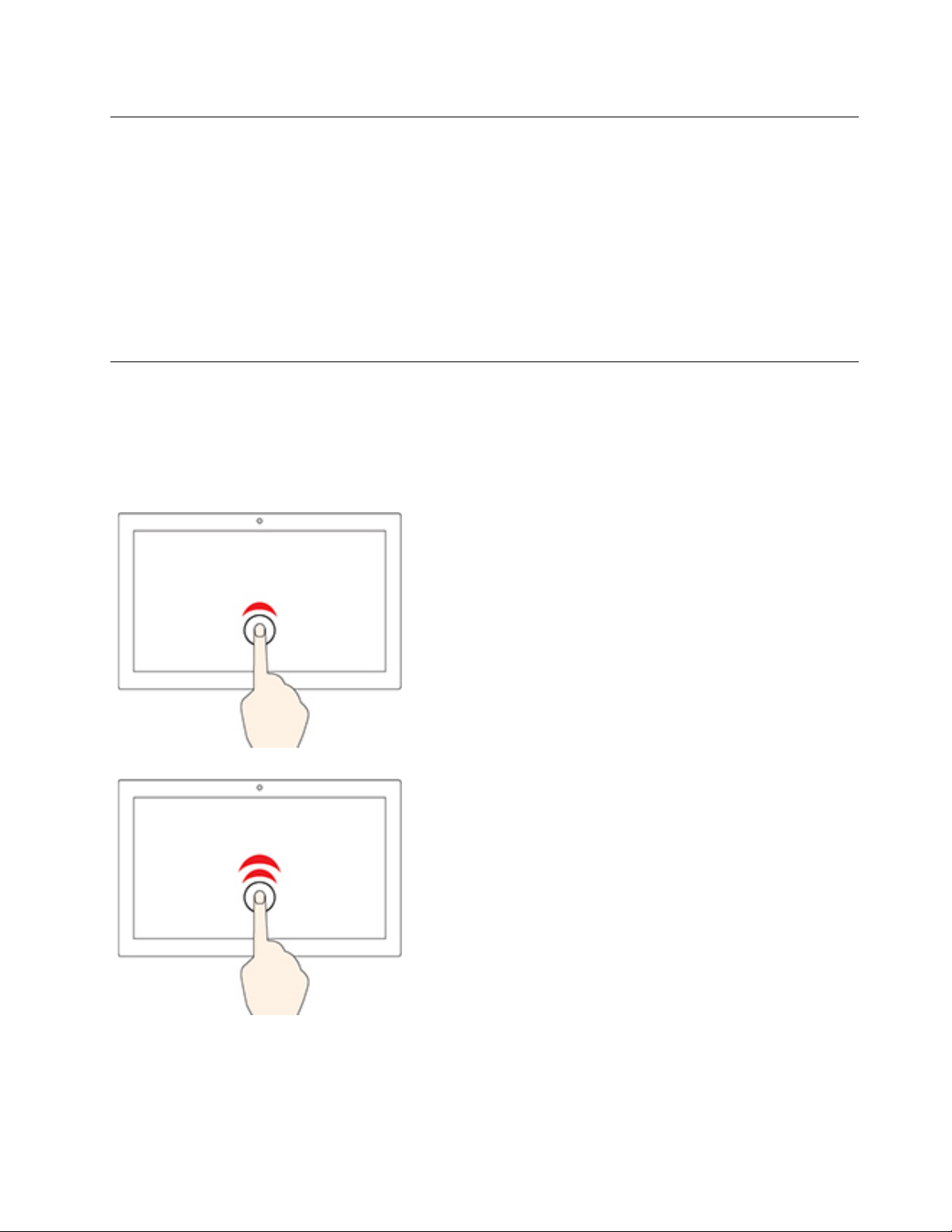
Use the multi-touch screen (for selected models)
If your computer display supports the multi-touch function, you can navigate the screen with simple touch
gestures.
Note: Some gestures might not be available depending on the app you use.
Tap once
• From the Start menu: Open an app or item.
• From the desktop: Select an app or item.
• In an open app: Perform an action such as Copy, Save, and
Delete, depending on the app.
Tap twice quickly
Open an app or item from the desktop.
Chapter 2. Get started with your computer 13
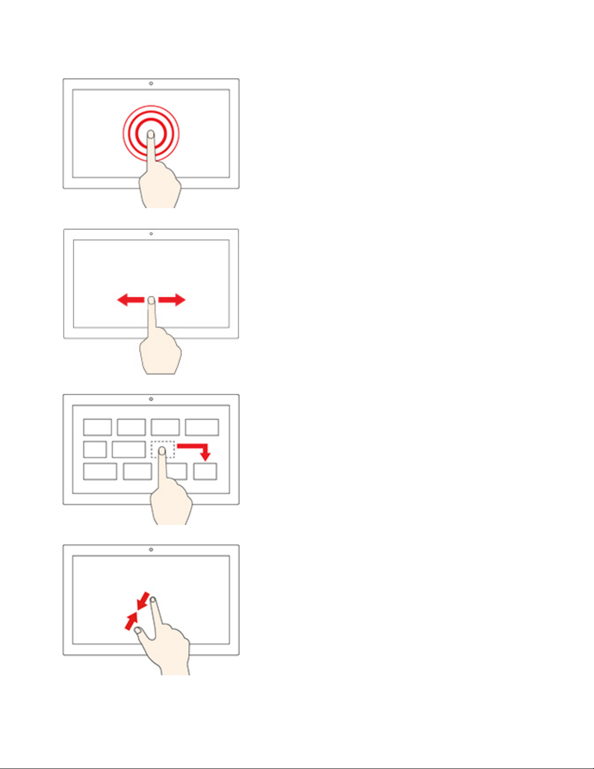
Tap and hold
Open a shortcut menu.
Slide
Scroll through items, such as lists, pages, and photos.
Drag an item to the location you want
Move an object.
Move two fingers closer together
Zoom out.
14 M70a and M90a User Guide
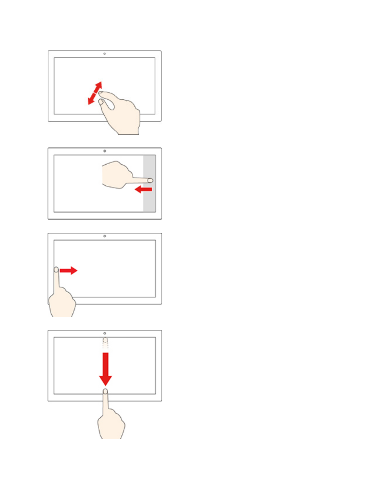
Move two fingers farther apart
Zoom in.
Swipe in from the right edge
Open the action center to see your notifications and quick actions.
Swipe in from the left edge
View all your open windows in task view.
• Swipe downwards shortly from the top edge (for full-screened
app or when your computer is in the tablet mode)
Show a hidden title bar.
• Swipe in from the top edge to the bottom edge (when your
computer is in the tablet mode)
Close the current app.
Chapter 2. Get started with your computer 15

Tips
• Turn off the computer before cleaning the multi-touch screen.
• Use a dry, soft, and lint-free cloth or a piece of absorbent cotton to remove fingerprints or dust from the
multi-touch screen. Do not apply solvents to the cloth.
• The multi-touch screen is a glass panel covered with a plastic film. Do not apply pressure or place any
metallic object on the screen, which might damage the touch panel or cause it to malfunction.
• Do not use fingernails, gloved fingers, or inanimate objects for input on the screen.
• Regularly calibrate the accuracy of the finger input to avoid a discrepancy.
Use multimedia
Use your computer for business or entertainment with the devices (such as a camera, a monitor, or
speakers).
Use audio
To enhance the audio experience, connect speakers, headphones, or a headset to the audio connector.
Adjust the volume
1. Click the volume icon in the Windows notification area on the taskbar.
2. Follow the on-screen instructions to adjust the volume. Click the speaker icon to mute the audio.
Change the sound settings
1. Go to Control Panel and view by category.
2. Click Hardware and Sound ➙ Sound.
3. Change the settings as you prefer.
Use the camera (for selected models)
You can use the camera to take photos or record videos.
To take photos or record a video:
1. Open the Start menu and click Camera. You also can type Camera in the search box.
2. To take a photo, click the camera icon. If you want to record video, click the video icon to switch to
video mode.
If you use other programs that provide features such as photographing, video capturing, and video
conference, the camera starts automatically when you enable the camera-required feature.
Connect to an external display
Connect your computer to a projector or a monitor to give presentations or expand your workspace.
Connect to a wired display
1. Connect the external display to the DisplayPort-out connector on your computer.
2. Connect the external display to an electrical outlet.
3. Turn on the external display.
If your computer cannot detect the external display, right-click an empty area of the desktop, and then click
Display settings ➙ Detect.
16
M70a and M90a User Guide

Connect to a wireless display
To use a wireless display, ensure that both your computer and the external display support the Miracast
®
feature.
• Open the Start menu, and then click Settings ➙ Devices ➙ Bluetooth & other devices ➙ Add
Bluetooth or other device. In the Add a device window, click Wireless display or dock. Then, follow the
instructions on the screen.
• Click the action center icon
in the Windows notification area and click Connect. Select the wireless
display and follow the on-screen instructions.
Set the display mode
Right-click a blank area on the desktop and select Display settings. Then, select a display mode of your
preference from the Multiple displays menu.
• Duplicate these displays: Display the same video output on both your computer screen and an external
display.
• Extend these displays: Extend the video output from your computer display to an external display. You
can drag and move items between the two displays.
• Show only on 1: Display the video output only on your computer screen.
• Show only on 2: Display the video output only on an external display.
If you show programs using DirectDraw or Direct3D
®
in full-screen mode, only the main display shows the
video output.
Change display settings
1. Right-click a blank area on the desktop and select Display settings.
2. Select the display that you want to configure.
3. Change display settings of your preference.
You can change the settings for both the computer display and the external display. For example, you can
define which one is the main display and which one is the secondary display. You also can change the
resolution and orientation.
Note: If you set a higher resolution for the computer display than the external display, only part of the screen
can be displayed on the external display.
Chapter 2. Get started with your computer 17

18 M70a and M90a User Guide

Chapter 3. Explore your computer
Manage power
Use the information in this section to achieve the best balance between performance and power efficiency.
Set power button behaviors
You can define what the power button does according to your preference. For example, by pressing the
power button, you can turn off the computer or put the computer to sleep or hibernation mode.
To change what the power button does:
1. Go to Control Panel and view by large icons or small icons.
2. Click Power Options ➙ Choose what the power buttons do.
3. Change the settings as you prefer.
Set the power plan
For ENERGY STAR® compliant computers, the following power plan takes effect when your computers have
been idle for a specified duration:
Table 1. Default power plan (when plugged into ac power)
• Turn off the display: After 10 minutes
• Put the computer to sleep: After 25 minutes
To awaken the computer from Sleep mode, press any key on your keyboard.
To reset the power plan to achieve the best balance between performance and power saving:
1. Go to Control Panel and view by large icons or small icons.
2. Click Power Options, and then choose or customize a power plan of your preference.
Transfer data
Quickly share your files using the built-in Bluetooth technology among devices with the same features. You
also can install a disc or media card to transfer data.
Connect to a Bluetooth-enabled device (for selected models)
You can connect all types of Bluetooth-enabled devices to your computer, such as a keyboard, a mouse, a
smartphone, or speakers. To ensure that the connection is successful, place the devices 10 meters (33 feet),
at most, from the computer.
1. Turn on Bluetooth on the computer.
a. Open the Start menu, and then click Settings ➙ Devices ➙ Bluetooth & other devices.
b. Turn on the Bluetooth switch.
2. Click Add Bluetooth or other device ➙ Bluetooth.
3. Select a Bluetooth device, and then follow the on-screen instructions.
© Copyright Lenovo 2020 19

Your Bluetooth device and computer will automatically connect the next time if the two devices are in range
of each other with Bluetooth turned on. You can use Bluetooth for data transfer or remote control and
communication.
Use the optical drive (for selected models)
If your computer has an optical drive, read the following information.
Know the type of your optical drive
1. Right-click the Start button to open the Start context menu.
2. Click Device Manager. Type the administrator password or provide confirmation, if prompted.
Install or remove a disc
1. With the computer on, press the eject/close button on the optical drive. The tray slides out of the drive.
2. Insert a disc into the tray or remove a disc from the tray, and then press the eject/close button again to
close the tray.
Note: If the tray does not slide out of the drive when you press the eject/close button, turn off the computer.
Then, insert a straightened paper clip into the emergency-eject hole adjacent to the eject/close button. Use
the emergency eject only in an emergency.
Record a disc
1. Insert a recordable disc into the optical drive that supports recording.
2. Do one of the following:
• Open the Start menu, and then click Settings ➙ Devices ➙ AutoPlay. Select or turn on Use
AutoPlay for all media and devices.
• Open Windows Media Player.
• Double-click the ISO file.
3. Follow the on-screen instructions.
Use a media card (for selected models)
If your computer has a SD-card slot, read the following information.
Install a media card
1. Locate the SD-card slot.
2. Ensure that the metal contacts on the card are facing the ones in the SD-card slot. Insert the card firmly
into the SD-card slot until it is secured in place.
Remove a media card
Attention: Before removing a media card, eject the card from the Windows operating system first.
Otherwise, data on the card might get corrupted or lost.
1. Click the triangular icon in the Windows notification area to show hidden icons. Then, right-click the
Safely Remove Hardware and Eject Media icon.
2. Select the corresponding item to eject the card from the Windows operating system.
3. Press the card and remove it from your computer. Store the card safely for future use.
20
M70a and M90a User Guide

Purchase accessories
Lenovo has a number of hardware accessories and upgrades to help expand the capabilities of your
computer. Options include memory modules, storage devices, network cards, power adapters, keyboards,
mice, and more.
To shop at Lenovo, go to
https://www.lenovo.com/accessories.
Chapter 3. Explore your computer 21

22 M70a and M90a User Guide
Chapter 4. Secure your computer and information
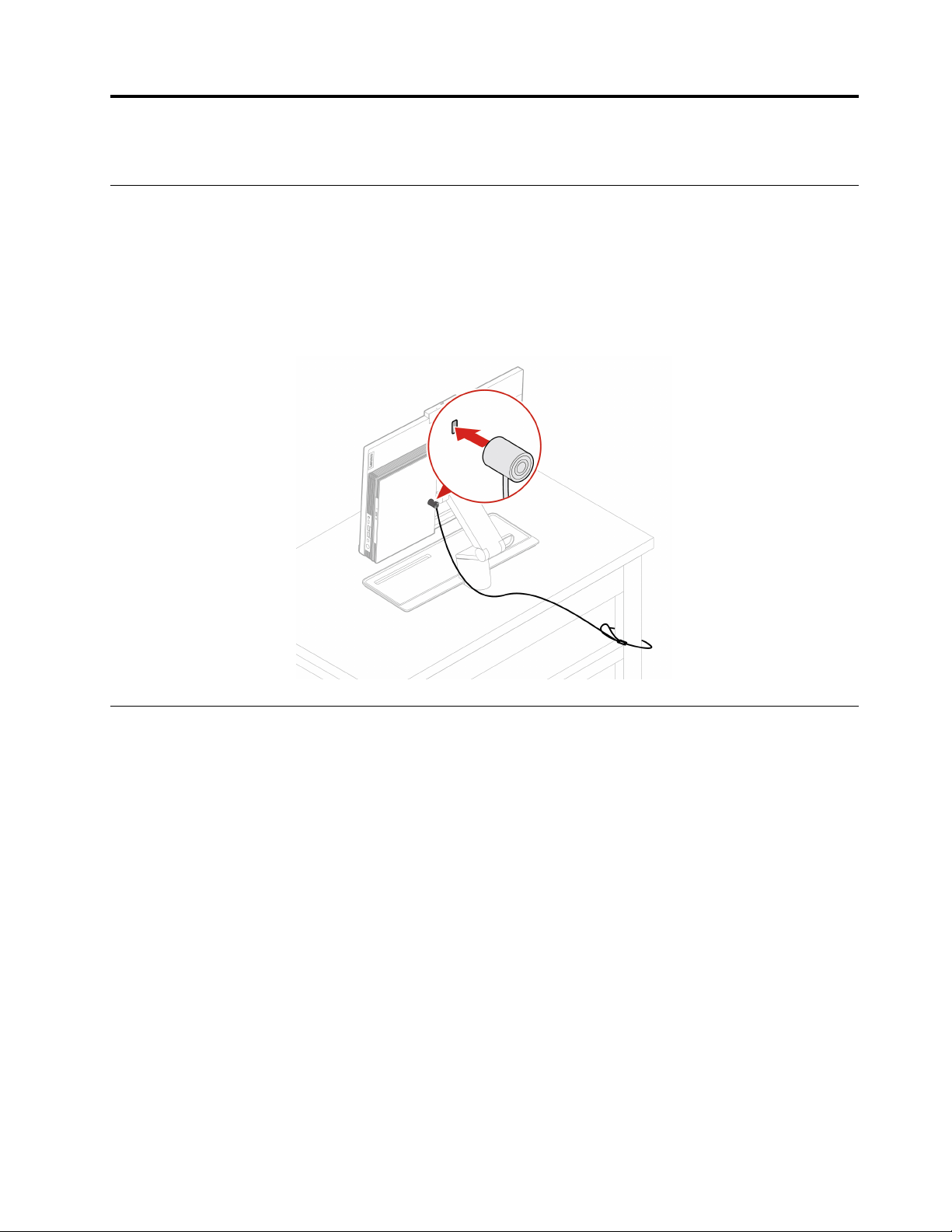
Lock the computer
Note: You are responsible for evaluating, selecting, and implementing the locking device and security
feature. Lenovo makes no comments, judgments, or warranties about the function, quality, or performance
of the locking device and security feature. You can purchase computer locks from Lenovo.
Kensington-style cable lock
Lock your computer to a desk, table, or other fixtures through a Kensington-style cable lock.
Log in to your computer securely
This section provides secure ways to log in to your computer with a password or your face.
Use passwords
Password types
You can set the following passwords in UEFI (Unified Extensible Firmware Interface) BIOS (Basic Input/
Output System) to prevent unauthorized access to your computer. However, you are not prompted to enter
any UEFI BIOS password when your computer resumes from sleep mode.
• Power-on password
When a power-on password is set, you are prompted to enter a valid password each time the computer is
turned on. The computer cannot be used until the valid password is entered.
• Supervisor password
Setting a supervisor password deters unauthorized users from changing configuration settings. If you are
responsible for maintaining the configuration settings of several computers, you might want to set a
supervisor password.
When a supervisor password is set, you are prompted to enter a valid password each time you try to enter
the BIOS menu.
© Copyright Lenovo 2020 23

If both the power-on password and supervisor password are set, you can enter either password.
However, you must use your supervisor password to change any configuration settings.
• Hard disk password
Setting a hard disk password prevents unauthorized access to the data on the storage drive. When a hard
disk password is set, you are prompted to enter a valid password each time you try to access the storage
drive.
Note: After you set a hard disk password, your data on the storage drive is protected even if the storage
drive is removed from one computer and installed in another.
• System management password (for selected models)
You can enable the system management password to have the same authority as the supervisor
password to control security related features. To customize the authority of the system management
password through the UEFI BIOS menu:
1. Restart the computer. When the logo screen is displayed, press F1 or Fn+F1.
2. Select Security ➙ System Management Password Access Control.
3. Follow the on-screen instructions.
If you have set both the supervisor password and the system management password, the supervisor
password overrides the system management password.
Set, change, and remove a password
Before you start, print these instructions.
1. Restart the computer. When the logo screen is displayed, press F1 or Fn+F1.
2. Select Security.
3. Depending on the password type, select Set Supervisor Password, Set Power-On Password, Set
System Management Password, or Hard Disk Password and press Enter.
4. Follow the on-screen instructions to set, change, or remove a password.
5. Press F10 or Fn+F10 to save the changes and exit.
You should record your passwords and store them in a safe place. If you forget the passwords, see “Clear
CMOS” on page 34 to remove them by yourself. You can also contact a Lenovo-authorized service provider
to have the passwords removed.
Notes:
• If the supervisor password is forgotten, it might not be removed by clearing CMOS depending on your
BIOS settings.
• If the hard disk password is forgotten, Lenovo cannot remove the password or recover data from the
storage drive.
Use face authentication (for selected models)
If your computer comes with a Windows Hello-compatible infrared camera, you can unlock your computer by
scanning your face instead of using a password.
Create face ID
1. Open the Start menu and click Settings ➙ Accounts ➙ Sign-in options.
2. Locate the Password section and click Add to create a password.
3. Follow the on-screen instructions to create a Personal Identification Number (PIN).
4. Locate the Windows Hello section and click Set up under Face Recognition. Then, click Get Started.
24
M70a and M90a User Guide

5. Enter the PIN you have set earlier. The camera preview starts.
6. Follow the on-screen instructions to complete the setup.
7. Click Improve Recognition to improve the image so that Windows Hello can recognize you in different
light conditions or when your appearance changes.
Log in with face authentication
1. On the Windows lock screen, select the smiling face icon
2. Follow the on-screen instructions and ensure that you are centered and looking directly at the camera.
When the program recognizes your face, it automatically unlocks the screen and signs you in to the
Windows operating system.
from the sign-in options.
Use software security solutions
This section provides software solutions to secure your computer and information.
Use firewalls
A firewall can be hardware, software, or a combination of both depending on the level of security required.
Firewalls work on a set of rules to determine which inbound and outbound connections are authorized. If the
computer is preinstalled with a firewall program, it helps protect against computer Internet security threats,
unauthorized access, intrusions, and Internet attacks. It also protects your privacy. For more information
about how to use the firewall program, refer to the help system of your firewall program.
To use firewalls:
1. Go to Control Panel and view by large icons or small icons.
2. Click Windows Defender Firewall, and then follow the on-screen instructions.
Use antivirus programs
The computer is preinstalled with an antivirus program to help you guard against, detect, and eliminate
viruses.
Lenovo provides a full version of antivirus software on the computer with a free 30-day subscription. After 30
days, you must renew the license to continue receiving the antivirus software updates.
Note: Virus definition files must be kept up-to-date to guard against new viruses.
For more information about how to use your antivirus software, refer to the help system of your antivirus
software.
Use computrace Agent software embedded in firmware (for selected models)
The Computrace Agent software is an IT asset management and computer theft recovery solution. The
software detects if changes have been made on the computer, such as hardware, software, or the computer
call-in location. You might have to purchase a subscription to activate the Computrace Agent software.
Use BIOS security solutions
This section provides BIOS solutions to secure your computer and information.
Chapter 4. Secure your computer and information 25

Erase all storage drive data
It is recommended that you erase all storage drive data before recycling a storage drive or the computer.
To erase all storage drive data:
1. Set a hard disk password for the storage drive you will recycle. See “Use passwords” on page 23.
2. Restart the computer. When the logo screen is displayed, press F1 or Fn+F1.
3. Select Security ➙ Hard Disk Password ➙ Security Erase HDD Data and press Enter.
4. Select the storage drive you will recycle and press Enter.
5. A message is displayed, prompting you to confirm the operation. Select Yes and press Enter. The
erasing process begins.
Note: During the erasing process, the power button and the keyboard are disabled.
6. After the erasing process is completed, a message is displayed, prompting you to reset the system.
Select Continue.
Note: Depending on the storage drive capacity, the erasing process will take half an hour to three hours.
7. After the resetting process is completed, one of the following will happen:
• If the data on the system storage drive is erased, you will be prompted that no operating system is
available.
• If the data on the non-system storage drive is erased, the computer restarts automatically.
Use the cover presence switch
The cover presence switch prevents the computer from logging in to the operating system when the
computer cover is not properly installed or closed.
To enable the cover presence switch connector on the system board:
1. Restart the computer. When the logo screen is displayed, press F1 or Fn+F1.
2. Select Security ➙ Cover Tamper Detected and press Enter.
3. Select Enabled and press Enter.
4. Press F10 or Fn+F10 to save the changes and exit.
When the cover presence switch connector on the system board is enabled, if the cover presence switch
detects that the computer cover is not correctly installed or closed, an error message will be displayed when
you turn on the computer. To bypass the error message and log in to the operating system:
1. Properly install or close the computer cover.
2. Enter the BIOS menu, save and then exit.
Use Intel BIOS guard
The BIOS guard module cryptographically verifies all the BIOS updates to the system BIOS flash. Therefore,
the malware is blocked from attacking the BIOS.
Use Smart USB Protection
The Smart USB Protection function is a security function that helps prevent data from being copied from the
computer to USB storage devices connected to the computer. You can set the Smart USB Protection
function to one of the following modes:
• Disabled (default setting): You can use the USB storage devices without limitation.
26
M70a and M90a User Guide

• Read Only: You cannot copy data from the computer to the USB storage devices. However, you can
access or modify data on the USB storage devices.
• No Access: You cannot access the USB storage devices from the computer.
To configure the Smart USB Protection function:
1. Restart the computer. When the logo screen is displayed, press F1 or Fn+F1.
2. Select Security ➙ Smart USB Protection and press Enter.
3. Select the desired setting and press Enter.
4. Press F10 or Fn+F10 to save the changes and exit.
Chapter 4. Secure your computer and information 27

28 M70a and M90a User Guide

Chapter 5. UEFI BIOS
This chapter provides information about configuring and updating UEFI BIOS, and clearing CMOS.
What is UEFI BIOS
Note: The operating system settings might override any similar settings in UEFI BIOS.
UEFI BIOS is the first program that the computer runs when the computer is turned on. UEFI BIOS initializes
the hardware components and loads the operating system and other programs. Your computer comes with a
setup program with which you can change UEFI BIOS settings.
Enter the BIOS menu
Restart the computer. When the logo screen is displayed, press F1 or Fn+F1 to enter the BIOS menu.
Note: If you have set BIOS passwords, enter the correct passwords when prompted. You also can select No
or press Esc to skip the password prompt and enter the BIOS menu. However, you cannot change the
system configurations that are protected by passwords.
Navigate in the BIOS interface
Attention: The default configurations are already optimized for you in boldface. Improper change of the
configurations might cause unexpected results.
Depending on your keyboard, you can navigate in the BIOS interface by pressing the following keys, or
combinations of Fn and the following keys:
F1 or Fn+F1
Esc or Fn+Esc Exit the submenu and return to the parent menu.
↑↓ or Fn+↑↓ Locate an item.
← → or Fn+← → Select a tab.
+/– or Fn++/– Change to a higher or lower value.
Enter Enter the selected tab or submenu.
F9 or Fn+F9 Restore to the default settings.
F10 or Fn+F10 Save your configuration and exit.
Display the General Help screen.
Change the display language of UEFI BIOS
UEFI BIOS supports three display languages: English, French, and simplified Chinese.
To change the display language of UEFI BIOS:
1. Select Main ➙ Language and press Enter.
2. Set the display language as desired.
© Copyright Lenovo 2020 29

Set the system date and time
1. Restart the computer. When the logo screen is displayed, press F1 or Fn+F1.
2. Select Main ➙ System Time & Date and press Enter.
3. Set the system date and time as desired.
4. Press F10 or Fn+F10 to save the changes and exit.
Change the startup sequence
If the computer does not start up from a device as expected, you can change the startup device sequence
permanently or select a temporary startup device.
Change the startup device sequence permanently
1. Depending on the type of the storage device, do one of the following:
• If the storage device is internal, go to step 2.
• If the storage device is a disc, ensure that the computer is on or turn on the computer. Then, insert
the disc into the optical drive.
• If the storage device is an external device other than a disc, connect the storage device to the
computer.
2. Restart the computer. When the logo screen is displayed, press F1 or Fn+F1.
3. Select Startup, and then follow the on-screen instructions to change the startup sequence.
4. Press F10 or Fn+F10 to save the changes and exit.
Select a temporary startup device
Note: Not all discs and storage drives are bootable.
1. Depending on the type of the storage device, do one of the following:
• If the storage device is internal, go to step 2.
• If the storage device is a disc, ensure that the computer is on or turn on the computer. Then, insert
the disc into the optical drive.
• If the storage device is an external device other than a disc, connect the storage device to the
computer.
2. Restart the computer. When the logo screen is displayed, press F12 or Fn+F12.
3. Select the storage device as desired and press Enter.
If you want to change the startup device sequence permanently, select Enter Setup on Startup Device Menu
and press Enter to enter the BIOS menu.
Enable or disable the configuration change detection feature
If you enable configuration change detection, when the POST detects configuration changes of some
hardware devices (such as storage drives or memory modules), an error message will be displayed when you
turn on the computer.
To enable or disable the configuration change detection feature:
1. Restart the computer. When the logo screen is displayed, press F1 or Fn+F1.
2. Select Security ➙ Configuration Change Detection and press Enter.
3. Enable or disable the feature as desired.
30
M70a and M90a User Guide

4. Press F10 or Fn+F10 to save the changes and exit.
To bypass the error message and log in to the operating system, press F2 or Fn+F2. To clear the error
message, enter the BIOS menu, save and then exit.
Enable or disable the automatic power-on feature
The Automatic Power On item in UEFI BIOS provides various options for you to make your computer start up
automatically.
To enable or disable the automatic power-on feature:
1. Restart the computer. When the logo screen is displayed, press F1 or Fn+F1.
2. Select Power ➙ Automatic Power On and press Enter.
3. Select the feature as desired and press Enter.
4. Enable or disable the feature as desired.
5. Press F10 or Fn+F10 to save the changes and exit.
Enable or disable the smart power-on feature
Ensure that the keyboard is connected to a USB connector supporting the smart power-on feature. With the
smart power-on feature enabled, you can start up or wake up the computer from the hibernation mode by
pressing Alt+P.
To enable or disable the smart power-on feature:
1. Restart the computer. When the logo screen is displayed, press F1 or Fn+F1.
2. Select Power ➙ Smart Power On and press Enter.
3. Enable or disable the feature as desired.
4. Press F10 or Fn+F10 to save the changes and exit.
Enable or disable the ErP LPS compliance mode
Lenovo computers meet the eco-design requirements of the ErP Lot 3 regulation. For more information, go
to:
https://www.lenovo.com/us/en/compliance/eco-declaration
You can enable the ErP LPS compliance mode to reduce the consumption of electricity when the computer
is off or in sleep mode.
To enable or disable the ErP LPS compliance mode:
1. Restart the computer. When the logo screen is displayed, press F1 or Fn+F1.
2. Select Power ➙ Enhanced Power Saving Mode and press Enter.
3. Depending on whether you select Enabled or Disabled, do one of the following:
• If you select Enabled, press Enter. Then, select Power ➙ Automatic Power On and press Enter.
Check whether the Wake on LAN feature is disabled automatically. If no, disable it.
• If you select Disabled, press Enter. Then, go to the next step.
4. Press F10 or Fn+F10 to save the changes and exit.
When the ErP LPS compliance mode is enabled, you can wake up the computer by doing one of the
following:
Chapter 5. UEFI BIOS 31

• Press the power button.
• Enable the Wake Up on Alarm feature to make the computer wake up at a set time.
To meet the off mode requirement of ErP compliance, you need to disable the Fast Startup function.
1. Go to Control Panel and view by large icons or small icons.
2. Click Power Options ➙ Choose what the power buttons do ➙ Change settings that are currently
unavailable.
3. Clear the Turn on fast startup (recommended) option from the Shutdown settings list.
Change the ICE performance mode
You can adjust the acoustic and thermal performance of your computer by changing the ICE performance
mode. Three choices are available:
• Best Performance (default setting): The computer works at a better thermal level with normal acoustic
performance.
• Best Experience: The computer works at the best experience with balanced noise and better
performance.
• Full Speed: All fans in the computer will run at full speed.
To change the ICE performance mode:
1. Restart the computer. When the logo screen is displayed, press F1 or Fn+F1.
2. Select Power ➙ Intelligent Cooling Engine (ICE) and press Enter.
3. Select ICE Performance Mode and press Enter.
4. Set the ICE performance mode as desired.
5. Press F10 or Fn+F10 to save the changes and exit.
Change BIOS settings before installing a new operating system
BIOS settings vary by operating system. Change the BIOS settings before installing a new operating system.
Microsoft constantly makes updates to the Windows 10 operating system. Before installing a particular
Windows 10 version, check the compatibility list for the Windows version. For details, go to:
https://support.lenovo.com/us/en/solutions/windows-support
To change the BIOS settings:
1. Restart the computer. When the logo screen is displayed, press F1 or Fn+F1.
2. From the main interface, select Security ➙ Secure Boot and press Enter.
3. Depending on the operating system to be installed, do one of the following:
• To install the Windows 10 (64-bit) and most of Linux operating system, select Enabled for Secure
Boot.
• To install an operating system that does not support secure boot, select Disabled for Secure Boot.
4. Press F10 or Fn+F10 to save the changes and exit.
Update UEFI BIOS
When you install a new program, device driver, or hardware component, you might need to update UEFI
BIOS. You can update the BIOS from your operating system or a flash update disc (supported only on
selected models).
32
M70a and M90a User Guide

Download and install the latest UEFI BIOS update package by one of the following methods:
• From Lenovo Vantage:
Open Lenovo Vantage to check the available update packages. If the latest UEFI BIOS update package is
available, follow the on-screen instructions to download and install the package.
• From the Lenovo Support Web site:
1. Go to
2. Download the flash BIOS update driver for the operating system version or the ISO image version
3. Print the installation instructions and follow the instructions to update the BIOS.
https://pcsupport.lenovo.com.
(used to create a flash update disc). Then, download the installation instructions for the flash BIOS
update driver you have downloaded.
Recover from a BIOS update failure
• M70a:
1. Remove all media from the drives and turn off all connected devices.
2. Insert the BIOS update disc into the optical drive, and then turn off the computer.
3. Disconnect all power cords from electrical outlets. Then, remove any parts that impede access to the
CLR1 button.
4. Reconnect the power cords for the computer and the monitor to electrical outlets.
5. Press and hold the CLR1 button, and then turn on the computer and the monitor.
6. Release the CLR1 button when the computer beeps. The recovery process begins.
Notes:
– Depending on the computer model, the recovery process will take two to three minutes.
– After the recovery process is completed, the computer will be automatically turned on or off
depending on the After Power Loss settings in the BIOS.
– Power On: The computer will be turned on automatically.
– Last State: The computer will be turned on automatically.
– Power Off: The computer will be turned off automatically.
7. Disconnect all power cords from electrical outlets.
8. Reinstall all the parts that have been removed. Then, reconnect the power cords for the computer and
the monitor to electrical outlets.
9. Turn on the computer and the monitor. When the logo screen is displayed, press F1 or Fn+F1.
10. To prevent data loss, ensure that BIOS settings are restored to an earlier point. For BIOS
configurations, see Chapter 5 “UEFI BIOS” on page 29.
• M90a:
1. Remove all media from the drives and turn off all connected devices.
2. Insert the BIOS update disc into the optical drive, and then turn off the computer.
3. Disconnect all power cords from electrical outlets. Then, remove any parts that impede access to the
Clear CMOS /Recovery jumper.
4. Move the jumper from the standard position to the maintenance position.
5. Reconnect the power cords for the computer and the monitor to electrical outlets.
6. Turn on the computer and the monitor. When the computer beeps, the recovery process begins.
7. After the recovery process is completed, the computer will be turned off automatically.
Chapter 5. UEFI BIOS 33

Note: Depending on the computer model, the recovery process will take two to three minutes.
8. Disconnect all power cords from electrical outlets.
9. Move the jumper back to the standard position.
10. Reinstall all the parts that have been removed. Then, reconnect the power cords for the computer and
the monitor to electrical outlets.
11. Turn on the computer and the monitor. When the logo screen is displayed, press F1 or Fn+F1.
12. To prevent data loss, ensure that BIOS settings are restored to an earlier point. For BIOS
configurations, see Chapter 5 “UEFI BIOS” on page 29.
Clear CMOS
• M70a:
1. Remove all media from the drives and turn off all connected devices and the computer.
2. Disconnect all power cords from electrical outlets. Then, remove any parts that impede access to the
CLR1 button.
3. Reconnect the power cords for the computer and the monitor to electrical outlets.
4. Press and hold the CLR1 button, and then turn on the computer and the monitor.
5. Release the CLR1 button when the computer beeps. Wait for approximately 10 seconds.
6. Turn off the computer by holding the power button for approximately four seconds.
7. Disconnect all power cords from electrical outlets.
8. Reinstall all the parts that have been removed. Then, reconnect the power cords for the computer and
the monitor to electrical outlets.
9. Turn on the computer and the monitor. When the logo screen is displayed, press F1 or Fn+F1.
10. To prevent data loss, ensure that BIOS settings are restored to an earlier point. For BIOS
configurations, see Chapter 5 “UEFI BIOS” on page 29.
• M90a:
1. Remove all media from the drives and turn off all connected devices and the computer.
2. Disconnect all power cords from electrical outlets. Then, remove any parts that impede access to the
Clear CMOS /Recovery jumper.
3. Move the jumper from the standard position to the maintenance position.
4. Reconnect the power cords for the computer and the monitor to electrical outlets.
5. Turn on the computer and the monitor. When the computer beeps, wait for approximately 10
seconds.
6. Turn off the computer by holding the power button for approximately four seconds.
7. Disconnect all power cords from electrical outlets.
8. Move the jumper back to the standard position.
9. Reinstall all the parts that have been removed. Then, reconnect the power cords for the computer and
the monitor to electrical outlets.
10. Turn on the computer and the monitor. When the logo screen is displayed, press F1 or Fn+F1.
11. To prevent data loss, ensure that BIOS settings are restored to an earlier point. For BIOS
configurations, see Chapter 5 “UEFI BIOS” on page 29.
34
M70a and M90a User Guide

Chapter 6. Troubleshooting, diagnostics, and recovery
This chapter provides solutions to resolve computer problems. Use the basic procedure as a starting point
for resolving computer problems.
Basic procedure for resolving computer problems
Prerequisite
Before you start, read Appendix A “Important safety information” on page 83 and print the following
instructions.
1. Check that:
a. The cables for all connected devices are connected correctly and securely.
b. All components have been reassembled correctly.
c. All connected devices that require ac power are connected to properly grounded and working
electrical outlets.
d. All connected devices are enabled in UEFI BIOS.
2. Use an antivirus program (if any) to see if the computer has been infected by a virus. If the program
detects a virus, remove the virus.
3. See Chapter 6 “Troubleshooting, diagnostics, and recovery” on page 35 to resolve the problem you are
experiencing, run the diagnostic program, and recover your operating system.
4. If the problem persists, contact Lenovo. See Chapter 8 “Help and support” on page 79.
Troubleshooting
Use the troubleshooting information to find solutions to problems that have definite symptoms.
© Copyright Lenovo 2020 35

Startup problems
Problem Solution
• Ensure that the power cord is correctly connected to the rear of the
computer and to a working electrical outlet.
The computer does not start up when you
press the power button.
The operating system does not start up from
the correct storage drive or fails to start up
• If the computer has a secondary power switch on the rear of the
computer, ensure that it is switched on.
• The power indicator on the front of the computer is on.
• The computer voltage matches the voltage available at the
electrical outlet for your country or region.
• Ensure that all storage drive signal cables and power cables are
connected correctly.
• Ensure that the storage drive the computer starts up from is listed
as the first startup device in UEFI BIOS.
• In rare cases, the storage drive with the operating system might get
corrupted or damaged. In such cases, you might need to replace
the storage drive.
• If the computer is installed with an Optane memory:
– Ensure that the Optane memory is not removed.
– Ensure that the Optane memory is not damaged. Check the
Optane memory using diagnostic tools.
The computer beeps multiple times before
the operating system starts up.
Ensure that no keys are stuck.
36 M70a and M90a User Guide

Screen problems
Problem Solution
• The computer voltage matches the voltage available at the
electrical outlet for your country or region.
• Press a key to exit the screen saver.
The screen goes blank while the computer is
on.
The image appears to be flickering.
• Press the power button to wake the computer from sleep or
hibernation mode.
• The brightness and contrast is set correctly.
• If the screen goes blank when some programs start, install the
device drivers for the programs. Refer to the documentation for the
affected program to check whether any device drivers are required.
• The screen might be affected by interference from nearby
equipment. Magnetic fields around other devices, such as
transformers, appliances, fluorescent lights, and other monitors,
might be causing the problem. Move fluorescent desk lighting or
any equipment that produces magnetic fields farther away from the
screen. If the problem persists, turn off the computer. Then, adjust
the placement of the computer and other devices so that they are
at least 305 mm (12 inches) apart. Turn on the computer.
• Reset the refresh rate.
1. Right-click a blank area on the desktop.
2. Click Display settings. On the Display tab, click Advanced
3. Click the Monitor tab, and then reset the refresh rate to be the
display settings ➙ Display adapter properties for Display 1.
highest and noninterlaced.
The image is discolored.
• The screen might be affected by interference from nearby
equipment. Move fluorescent desk lighting or any equipment that
produces magnetic fields farther away from the screen.
• Turn off the computer. Then, adjust the placement of the computer
and other devices so that they are at least 305 mm (12 inches)
apart. Turn on the computer.
Chapter 6. Troubleshooting, diagnostics, and recovery 37

Audio problems
Problem Solution
• If you are using powered external speakers that have an On/Off
control, ensure that:
– The On/Off control is set to the On position.
– The speaker power cable is connected to a properly grounded,
• If your external speakers have a volume control, ensure that the
volume is not set too low.
• Click the volume icon in the Windows notification area on the
taskbar. Check the speaker and volume settings. Do not mute the
speaker or set the volume at a very low level.
• If your computer has a front audio panel, ensure that the volume is
not set too low.
The audio cannot be heard on the Windows
operating system.
• Ensure that your external speakers (and headphones, if used) are
connected to the correct audio connector on the computer. Most
speaker cables are color-coded to match the audio connector.
Note: When external-speaker or headphone cables are connected
to the audio connector, the internal speaker, if present, is disabled.
In most cases, if an audio adapter is installed in one of the
expansion slots, the audio function built into the system board is
disabled. Therefore, you must use the audio connectors on the
audio adapter.
• Ensure that the program you are running is designed for use in the
Microsoft Windows operating system. If the program is designed to
run in DOS, the program does not use the Windows sound feature.
The program must be configured to use SoundBlaster Pro or
SoundBlaster emulation.
• Ensure that the audio device drivers are correctly installed.
functional ac electrical outlet.
The sound does not come from the headset
or headphones.
The sound comes from one of the external
speakers.
Select the headset or headphones as the default audio output device
in advanced sound settings.
• Ensure that the speaker cable is inserted completely into the
connector on the computer.
• Ensure that the cable that connects the left speaker to the right
speaker is securely connected.
• Ensure that the balance settings are set correctly.
1. Right-click the volume icon in the Windows notification area
2. Click the speaker icon on top of the volume control, and then
Network problems
Note: The Wi-Fi and Bluetooth features are optional.
on the taskbar. Then, click Open Volume Mixer and select the
desired speaker.
click the Levels tab.
38
M70a and M90a User Guide

Problem Solution
• Connect the cable from the Ethernet connector to the RJ45
connector of the hub.
• Enable the Ethernet LAN feature in UEFI BIOS.
• Enable the Ethernet LAN adapter.
1. Go to Control Panel and view by large icons or small icons.
2. Click Network and Sharing Center ➙ Change adapter
The computer cannot connect to an Ethernet
LAN.
3. Right-click the Ethernet LAN adapter icon and click Enable.
• Update or reinstall the Ethernet LAN driver.
• Install all networking software that is necessary for your network
environment. Check with your LAN administrator for the necessary
networking software.
• Set the same duplex for the switch port and the adapter. If you
configured the adapter for full duplex, ensure that the switch port is
also configured for full duplex. Setting a wrong duplex mode might
degrade performance, cause data loss, or result in lost
connections.
When a Gigabit Ethernet model computer is
used at a speed of 1000 Mbps, the Ethernet
LAN connection fails or errors occur.
The Wake On LAN (WOL) feature does not
work.
Connect the network cable to the Ethernet connector using Category
5 wiring and a 100 BASE-T hub/switch (not 100 BASE-X).
Enable the Wake On LAN feature in UEFI BIOS.
settings.
The Wi-Fi feature does not work.
• Enable the Wi-Fi feature in UEFI BIOS.
• Enable all Wi-Fi devices.
1. Right-click the Start button to open the Start context menu.
2. Click Device Manager. Type the administrator password or
provide confirmation, if prompted.
3. Expand Network adapters to display all network devices.
4. Right-click each Wi-Fi device, and then click Enable device.
• Enable the Wi-Fi feature in Windows Settings.
1. Open the Start menu.
2. Click Settings ➙ Network & Internet ➙ Wi-Fi.
3. Enable the Wi-Fi feature.
• Update or reinstall the Wi-Fi driver.
Chapter 6. Troubleshooting, diagnostics, and recovery 39

Problem Solution
• Enable the Bluetooth feature in UEFI BIOS.
• Enable all Bluetooth devices.
1. Right-click the Start button to open the Start context menu.
2. Click Device Manager. Type the administrator password or
3. Expand Bluetooth to display all Bluetooth devices. Right-click
The Bluetooth feature does not work.
4. Expand Network adapters to display all network devices.
• Turn on the Bluetooth radio.
1. Open the Start menu.
2. Click Settings ➙ Devices ➙ Bluetooth & other devices.
3. Turn on the Bluetooth switch to enable the Bluetooth feature.
• Update or reinstall the Bluetooth driver.
provide confirmation if prompted.
each Bluetooth device, and then click Enable device.
Right-click each Bluetooth device, and then click Enable
device.
Sound does not come from the Bluetooth
headset or headphones.
Select the Bluetooth headset or headphones as the default audio
output device in advanced sound settings.
40 M70a and M90a User Guide

Performance problems
Problem Solution
Note: Depending on the volume of the storage drives and amount of
data stored on the storage drives, the disk-defragmentation process
might take up to several hours.
1. Close any open programs and windows.
2. Open the Start menu.
Excessive fragmented files exist on the
storage drives.
The free storage drive space is insufficient.
3. Click Windows System ➙ File Explorer ➙ This PC.
4. Right-click your C drive and then click Properties.
5. Click the Tools tab.
6. Click Optimize. Select the drive as desired, and then click
7. Follow the on-screen instructions.
• Clean out your Inbox, Sent Items, and Deleted Items folders from
your e-mail application.
• Clean up your C drive.
1. Open the Start menu.
2. Click Windows System ➙ File Explorer ➙ This PC.
3. Right-click your C drive and then click Properties.
4. Check the amount of free space, and then click Disk Cleanup.
5. A list of unnecessary file categories is displayed. Select the
• Disable some Windows features or remove some unnecessary
programs.
1. Go to Control Panel and view by large icons or small icons.
2. Click Programs and Features.
3. Do one of the following:
Optimize.
category you want to delete, and then click OK.
– To disable some Windows features, click Turn Windows
features on or off. Follow the on-screen instructions.
– To remove some unnecessary programs, select the
program you want to remove, and then click Uninstall/
Change or Uninstall.
The free memory space is insufficient.
• Right-click a blank area on the taskbar and open Task Manager.
Then, end some tasks you are not performing.
• Install additional memory modules.
Chapter 6. Troubleshooting, diagnostics, and recovery 41

Storage drive problems
Problem Solution
• Ensure that the signal cables and power cables for all the storage
drives are connected correctly.
• Ensure that the computer is configured correctly to support the
storage drives.
Some or all storage drives are missing from
the BIOS menu.
– If the computer is installed with SATA storage drives, ensure
– If the computer is installed with SAS storage drives, ensure that
CD or DVD problems
Problem Solution
• Ensure that the optical drive supports the CD or DVD.
• Ensure that the disc is inserted correctly, with its label up.
• Ensure that the disc you are using is clean. To remove dust or
fingerprints, wipe the disc clean with a soft cloth from the center to
the outside. Wiping a disc in a circular motion might cause loss of
data.
A CD or DVD does not work.
• Ensure that the power cable and signal cable are securely
connected to the drive.
• Ensure that the disc you are using is not scratched or damaged.
Try inserting another disc that you know works.
• If you have multiple CD or DVD drives installed (or a combination of
CD and DVD drives), try inserting the disc into the other drive. In
some cases, only one of the drives is connected to the audio
subsystem.
that the SATA storage drive enablement module (one to five
storage drives) is installed.
the SAS storage drive enablement module (one to five storage
drives) or the LSI MegaRAID SAS adapter is installed.
A bootable recovery medium, such as the
Product Recovery CD, cannot be used to
start your computer.
A black screen is displayed instead of the
DVD video.
A DVD movie does not play.
No audio or only an intermittent audio comes
out while a DVD movie is playing.
42 M70a and M90a User Guide
Ensure that the CD or DVD drive is set as the top priority of the boot
priority order in UEFI BIOS.
Note: On some computer models, the startup sequence is
permanently set and cannot be changed.
• Restart the DVD player program.
• Try a lower screen resolution or color depth.
• Close any open files, and then restart the computer.
• Ensure that the disc surface is clean and not scratched.
• Check the disc or package for regional coding. You might need to
purchase a disc with coding for the region where you are using the
computer.
• Check the volume control settings on the computer and on your
speakers.
• Ensure that the disc surface is clean and not scratched.
• Check all cable connections to and from the speakers.
• Use the DVD menu for the video to select a different audio track.

Problem Solution
• Disable any background programs, such as AntiVirus or Desktop
The playback is slow or choppy.
A message indicating invalid disc or no disc
found is displayed.
Themes.
• Ensure that video resolution is less than 1152 x 864 pixels.
• Ensure that the disc is in the drive with the shiny side of the disc
facing down.
• Ensure that video resolution is less than 1152 x 864 pixels.
• Ensure that the DVD or CD is inserted into an appropriate optical
drive. For example, do not insert a DVD into a CD-only drive.
Serial connector problems
Problem Solution
• Connect the serial cable from the serial connector on the computer
to the serial device. If the serial device has its own power cord,
connect the power cord to a grounded electrical outlet.
• Turn on the serial device and keep the device online.
The serial connector cannot be accessed.
• Install any programs supplied with the serial device. Refer to the
documentation that comes with the serial device for more
information.
• If you added one serial-connector adapter, ensure that the adapter
is installed correctly.
USB device problems
Problem Solution
• Connect the USB cable from the USB connector to the USB
device. If the USB device has its own power cord, connect the
power cord to a grounded electrical outlet.
• Turn on the USB device and keep the device online.
A USB device cannot be accessed.
• Install any device drivers or programs supplied with the USB
device. Refer to the documentation that comes with the USB
device for more information.
• Disconnect and reconnect the USB connector to reset the USB
device.
• Ensure that the Smart USB Protection function is disabled in UEFI
BIOS.
Chapter 6. Troubleshooting, diagnostics, and recovery 43

Software problems
Problem Solution
1. Check whether the problem is caused by a program.
a. Ensure that the software is compatible with the computer.
Refer to the information supplied with the software for more
information.
b. Verify that other software works correctly on the computer.
c. Verify that the software you are using works on another
Some programs do not work as expected.
computer.
2. If the problem is caused by a program:
• Refer to the printed documentation that comes with the
program or the help system of the program.
• Update the program.
• Uninstall the program and then reinstall it. To download a
program that is preinstalled on your computer, go to
pcsupport.lenovo.com
and follow the on-screen instructions.
https://
Diagnostics
Use diagnostic solutions to test hardware components and report operating-system-controlled settings that
interfere with the correct operation of your computer.
Lenovo diagnostic tools
For information about Lenovo diagnostic tools, go to:
https://pcsupport.lenovo.com/lenovodiagnosticsolutions
Recovery
This section introduces the recovery information of the Windows 10 operating system. Ensure that you read
and follow the on-screen recovery instructions. The data on your computer might be deleted during the
recovery process. To avoid data loss, make a backup copy of all the data that you want to keep.
Restore system files and settings to an earlier point
1. Go to Control Panel and view by large icons or small icons.
2. Click Recovery ➙ Open System Restore. Then, follow the on-screen instructions.
Restore your files from a backup
Note: If you use the File History tool to restore your files from a backup, ensure that you backed up your
data earlier with the tool.
1. Go to Control Panel and view by large icons or small icons.
2. Click File History ➙ Restore personal files. Then, follow the on-screen instructions.
Reset your computer
In the resetting process, you can choose to keep your files or remove them when you reinstall the operating
system.
Note: The items in the graphical user interface (GUI) might change without notice.
44
M70a and M90a User Guide

1. Open the Start menu, and then click Settings ➙ Update & Security ➙ Recovery.
2. In the Reset this PC section, click Get started.
3. Follow the on-screen instructions to reset your computer.
Use advanced options
1. Open the Start menu, and then click Settings ➙ Update & security ➙ Recovery.
2. In the Advanced startup section, click Restart now ➙ Troubleshoot ➙ Advanced options.
3. Select a preferred option, and then follow the on-screen instructions.
Windows automatic recovery
Note: Ensure that your computer is connected to ac power during the recovery process.
The Windows recovery environment on your computer operates independently from the Windows 10
operating system. It enables you to recover or repair the operating system even if the Windows 10 operating
system fails to start.
After two consecutive failed boot attempts, the Windows recovery environment starts automatically. Then,
you can choose repair and recovery options by following the on-screen instructions.
Create and use a recovery USB device
It is recommended that you create a recovery USB drive as early as possible as a backup for the Windows
recovery programs. With the recovery USB drive, you can troubleshoot and fix the problems even if the
preinstalled Windows recovery programs are damaged. If you did not create a recovery USB drive as a
precautionary measure, you can contact Lenovo Customer Support Center and purchase one from Lenovo.
For a list of the Lenovo Support phone numbers for your country or region, go to:
https://pcsupport.lenovo.com/supportphonelist
Create a recovery USB drive
Attention: The creation process deletes anything stored on the USB drive. To avoid data loss, make a
backup copy of all the data that you want to keep.
1. Ensure that your computer is connected to ac power.
2. Prepare a USB drive with capacity of at least 16 GB. The actual USB capacity required depends on the
size of the recovery image.
3. Connect the prepared USB drive to the computer.
4. Type recovery in the search box. Then, click Create a recovery drive.
5. Click Yes in the User Account Control window to allow the Recovery Media Creator program to start.
6. In the Recovery Drive window, follow the on-screen instructions to create a recovery USB drive.
Use the recovery USB drive
If your computer cannot be started, go to Chapter 8 “Help and support” on page 79 first to try to solve the
problem by yourself. If the problem persists, use the recovery USB drive to recover your computer.
1. Ensure that your computer is connected to ac power.
2. Connect the recovery USB drive to the computer.
3. Turn on or restart the computer. When the logo screen is displayed, press F12. The Boot Menu window
opens.
4. Select the recovery USB drive as the boot device.
Chapter 6. Troubleshooting, diagnostics, and recovery 45

5. Click Troubleshoot to display optional recovery solutions.
6. Select a recovery solution as desired. Then, follow the on-screen instructions to complete the process.
Update the device driver
Attention: Reinstalling device drivers will change the current configuration of the computer.
You should download the latest driver for a component when you notice poor performance from that
component or when you added a component. This action might eliminate the driver as the potential cause of
a problem. Download and install the latest driver by one of the following methods:
• From Lenovo Vantage:
Open Lenovo Vantage to check the available update packages. If the latest UEFI BIOS update package is
available, follow the on-screen instructions to download and install the package.
• From the Lenovo Support Web site:
Go to
https://pcsupport.lenovo.com and select the entry for your computer. Then, follow the on-screen
instructions to download and install necessary drivers and software.
• From Windows Update:
Note: The device drivers provided by Windows Update might not be tested by Lenovo. It is
recommended that you get device drivers from Lenovo.
1. Open the Start menu.
2. Click Settings ➙ Update & Security ➙ Windows Update.
3. Follow the on-screen instructions.
46
M70a and M90a User Guide

Chapter 7. CRU replacement
What are CRUs
Customer Replaceable Units (CRUs) are parts that can be upgraded or replaced by the customer. Lenovo
computers contain the following types of CRUs:
• Self-service CRUs: Refer to parts that can be installed or replaced easily by customer themselves or by
trained service technicians at an additional cost.
• Optional-service CRUs: Refer to parts that can be installed or replaced by customers with a greater skill
level. Trained service technicians can also provide service to install or replace the parts under the type of
warranty designated for the customer’s machine.
If you intend on installing the CRU, Lenovo will ship the CRU to you. CRU information and replacement
instructions are shipped with your product and are available from Lenovo at any time upon request. You
might be required to return the defective part that is replaced by the CRU. When return is required: (1) return
instructions, a prepaid shipping label, and a container will be included with the replacement CRU; and (2) you
might be charged for the replacement CRU if Lenovo does not receive the defective CRU within thirty (30)
days of your receipt of the replacement CRU. For full details, see the Lenovo Limited Warranty
documentation at:
https://www.lenovo.com/warranty/llw_02
Refer to the following CRU list for your computer.
Self-service CRUs
• Computer stand*
• Computer stand base*
• Keyboard*
• Mouse*
• Power adapter
• Power cord
Optional-service CRUs
• M.2 solid-state drive*
• Memory module
• Optical drive*
• Optical drive holder*
• Rear cover
• System board shield
• Storage drive*
• Storage drive bracket
• VESA
• VESA mount bracket cover
* for selected models
© Copyright Lenovo 2020 47
®
mount bracket

Replace a CRU
Follow the replacement procedure to replace a CRU.
Computer stand
Prerequisite
Before you start, read Appendix A “Important safety information” on page 83 and print the following
instructions.
Replacement procedure
1. Turn off the computer and remove all connected devices and cables.
2. Disconnect the computer from ac power and all connected cables.
3. Place a soft, clean towel or cloth on the desk or surface. Hold the sides of your computer and gently lay
it down so that the screen is against the surface and the computer cover is facing up.
4. Depending on your computer stand, refer to one of the following to replace the computer stand.
• Full-function monitor stand.
Figure 3. Removing the full-function monitor stand
48 M70a and M90a User Guide

Figure 4. Removing the full-function monitor stand base
Figure 5. Installing the full-function monitor stand base
Chapter 7. CRU replacement 49

Figure 6. Installing the full-function monitor stand
• UltraFlex IV Stand.
Figure 7. Removing the UltraFlex IV Stand
50 M70a and M90a User Guide

Figure 8. Removing the UltraFlex IV Stand base
Figure 9. Installing the UltraFlex IV Stand base
Chapter 7. CRU replacement 51

Figure 10. Installing the UltraFlex IV Stand
5. Place the computer in an upright position.
6. Reconnect the ac power adapter and all disconnected cables to the computer.
Rear cover
Prerequisite
Before you start, read Appendix A “Important safety information” on page 83 and print the following
instructions.
CAUTION:
Before you open the rear cover, turn off the computer and wait several minutes until the computer is
cool.
Replacement procedure
1. Turn off the computer and remove all connected devices and cables.
2. Disconnect the computer from ac power and all connected cables.
3. Unlock any locking device that secures the computer cover.
4. Place a soft, clean towel or cloth on the desk or surface. Hold the sides of your computer and gently lay
it down so that the screen is against the surface and the computer cover is facing up.
5. Remove the computer stand. See “Computer stand” on page 48.
6. Replace the rear cover.
52
M70a and M90a User Guide

Figure 11. Removing the rear cover
Figure 12. Installing the rear cover
7. Reinstall the computer stand. See “Computer stand” on page 48.
8. Place the computer in an upright position.
9. If a locking device is available, use it to lock the computer.
10. Reconnect the external cables and power cords to the corresponding connectors on the computer.
Optical drive
Prerequisite
Before you start, read Appendix A “Important safety information” on page 83 and print the following
instructions.
Replacement procedure
1. Remove the computer stand. See “Computer stand” on page 48.
2. Remove the rear cover. See “Rear cover” on page 52.
Chapter 7. CRU replacement 53

3. Disconnect the power and signal cable from the optical drive.
4. Depending on your computer model, refer to one of the following to replace the optical drive.
• M70a
Figure 13. Removing the optical drive
Figure 14. Removing the optical drive bracket
Figure 15. Installing the optical drive bracket
54 M70a and M90a User Guide

Figure 16. Installing the optical drive
• M90a
Figure 17. Removing the optical drive
Figure 18. Removing the optical drive bracket
Chapter 7. CRU replacement 55

Figure 19. Installing the optical drive bracket
Figure 20. Installing the optical drive
5. Reconnect the power and signal cable to the optical drive.
6. Reinstall the removed parts.
7. Place the computer in an upright position.
8. If a locking device is available, use it to lock the computer.
9. Reconnect the external cables and power cords to the corresponding connectors on the computer.
Optical drive holder
Prerequisite
Before you start, read Appendix A “Important safety information” on page 83 and print the following
instructions.
Replacement procedure
1. Remove the computer stand. See “Computer stand” on page 48.
2. Remove the rear cover. See “Rear cover” on page 52.
3. Remove the optical drive. See “Optical drive” on page 53.
4. Depending on your computer model, refer to one of the following to replace the optical drive holder.
• M70a
56
M70a and M90a User Guide

Figure 21. Removing the optical drive holder
Figure 22. Installing the optical drive holder
• M90a
Chapter 7. CRU replacement 57

Figure 23. Removing the optical drive holder
Figure 24. Installing the optical drive holder
5. Place the computer in an upright position.
6. If a locking device is available, use it to lock the computer.
7. Reconnect the external cables and power cords to the corresponding connectors on the computer.
System board shield
Prerequisite
Before you start, read Appendix A “Important safety information” on page 83 and print the following
instructions.
Replacement procedure
1. Remove the computer stand. See “Computer stand” on page 48.
58
M70a and M90a User Guide

2. Remove the rear cover. See “Rear cover” on page 52.
3. Remove the optical drive. See “Optical drive” on page 53.
4. Remove the optical drive holder. See “Optical drive holder” on page 56.
5. Depending on your computer model, refer to one of the following to replace the system board shield.
• M70a
Figure 25. Removing the system board shield
Figure 26. Installing the system board shield
Chapter 7. CRU replacement 59

Figure 27. Installing the system board shield screw
• M90a
Figure 28. Removing the system board shield
Figure 29. Installing the system board shield
60 M70a and M90a User Guide

6. Reinstall the removed parts.
7. Place the computer in an upright position.
8. If a locking device is available, use it to lock the computer.
9. Reconnect the external cables and power cords to the corresponding connectors on the computer.
VESA mount bracket cover
Prerequisite
Before you start, read Appendix A “Important safety information” on page 83 and print the following
instructions.
CAUTION:
Before you open the VESA mount bracket cover, turn off the computer and wait several minutes until
the computer is cool.
Replacement procedure
1. Remove the computer stand. See “Computer stand” on page 48.
2. Remove the rear cover. See “Rear cover” on page 52.
3. Remove the optical drive. See “Optical drive” on page 53.
4. Remove the optical drive holder. See “Optical drive holder” on page 56.
5. Remove the system board shield. See “System board shield” on page 58.
6. Depending on your computer model, refer to one of the following to replace the VESA mount bracket
cover.
• M70a
Figure 30. Opening the cable cover
Chapter 7. CRU replacement 61

Figure 31. Removing the VESA mount bracket cover
Figure 32. Installing the VESA mount bracket cover
• M90a
Figure 33. Opening the cable cover
62 M70a and M90a User Guide

Figure 34. Removing the VESA mount bracket cover
Figure 35. Installing the VESA mount bracket cover
7. Reinstall the removed parts.
8. Place the computer in an upright position.
9. If a locking device is available, use it to lock the computer.
10. Reconnect the external cables and power cords to the corresponding connectors on the computer.
VESA mount bracket
Prerequisite
Before you start, read Appendix A “Important safety information” on page 83 and print the following
instructions.
Replacement procedure
1. Remove the computer stand. See “Computer stand” on page 48.
2. Remove the rear cover. See “Rear cover” on page 52.
Chapter 7. CRU replacement 63

3. Remove the optical drive. See “Optical drive” on page 53.
4. Remove the optical drive holder. See “Optical drive holder” on page 56.
5. Remove the system board shield. See “System board shield” on page 58.
6. Remove the VESA mount bracket cover. See “VESA mount bracket cover” on page 61.
7. Depending on your computer model, refer to one of the following to replace the VESA mount bracket.
• M70a
Figure 36. Removing the VESA mount bracket
Figure 37. Installing the VESA mount bracket
• M90a
64
M70a and M90a User Guide

Figure 38. Removing the VESA mount bracket
Figure 39. Installing the VESA mount bracket
8. Reinstall the removed parts.
9. Place the computer in an upright position.
10. If a locking device is available, use it to lock the computer.
11. Reconnect the external cables and power cords to the corresponding connectors on the computer.
Storage drive and storage drive bracket
Prerequisite
Before you start, read Appendix A “Important safety information” on page 83 and print the following
instructions.
Replacement procedure
1. Remove the computer stand. See “Computer stand” on page 48.
2. Remove the rear cover. See “Rear cover” on page 52.
Chapter 7. CRU replacement 65

3. Remove the optical drive. See “Optical drive” on page 53.
4. Remove the optical drive holder. See “Optical drive holder” on page 56.
5. Remove the system board shield. See “System board shield” on page 58.
6. Depending on your computer model, refer to one of the following to replace the storage drive and the
storage drive bracket.
• M70a
Figure 40. Removing the storage drive and the bracket
Figure 41. Removing the storage drive from the bracket
66 M70a and M90a User Guide

Figure 42. Disconnecting the storage drive cable
Figure 43. Connecting the storage drive cable
Figure 44. Installing the storage drive to the bracket
Chapter 7. CRU replacement 67

Figure 45. Installing the storage drive and the bracket
• M90a
Figure 46. Removing the storage drive and the bracket
Figure 47. Removing the storage drive from the bracket
68 M70a and M90a User Guide

Figure 48. Disconnecting the storage drive cable
Figure 49. Connecting the storage drive cable
Figure 50. Installing the storage drive to the bracket
Chapter 7. CRU replacement 69

Figure 51. Installing the storage drive and the bracket
7. Reinstall the removed parts.
8. Place the computer in an upright position.
9. If a locking device is available, use it to lock the computer.
10. Reconnect the external cables and power cords to the corresponding connectors on the computer.
M.2 solid-state drive
Prerequisite
Before you start, read Appendix A “Important safety information” on page 83 and print the following
instructions.
Replacement procedure
1. Remove the computer stand. See “Computer stand” on page 48.
2. Remove the rear cover. See “Rear cover” on page 52.
3. Remove the optical drive. See “Optical drive” on page 53.
4. Remove the optical drive holder. See “Optical drive holder” on page 56.
5. Remove the system board shield. See “System board shield” on page 58.
6. Remove the VESA mount bracket cover. See “VESA mount bracket cover” on page 61.
7. Remove the VESA mount bracket. See “VESA mount bracket” on page 63.
8. Depending on your computer model, refer to one of the following to replace the M.2 solid-state drive.
• M70a
– For M.2 solid-state drive (2280) models
70
M70a and M90a User Guide

Figure 52. Removing the M.2 solid-state drive
Figure 53. Installing the M.2 solid-state drive
– For M.2 solid-state drive (2242) models
Chapter 7. CRU replacement 71

Figure 54. Removing the M.2 solid-state drive
Figure 55. Installing the M.2 solid-state drive
• M90a
– For M.2 solid-state drive (2280) models
72
M70a and M90a User Guide

Figure 56. Removing the M.2 solid-state drive
Figure 57. Installing the M.2 solid-state drive
– For M.2 solid-state drive (2242) models
Chapter 7. CRU replacement 73

Figure 58. Removing the M.2 solid-state drive
Figure 59. Installing the M.2 solid-state drive
9. Reinstall the removed parts.
10. Place the computer in an upright position.
11. If a locking device is available, use it to lock the computer.
12. Reconnect the external cables and power cords to the corresponding connectors on the computer.
Memory module
Prerequisite
Before you start, read Appendix A “Important safety information” on page 83 and print the following
instructions.
74
M70a and M90a User Guide

Replacement procedure
Ensure that you follow the installation order for memory modules shown in the following figure.
Figure 60. M70a memory module slots
Chapter 7. CRU replacement 75

Figure 61. M90a memory module slots
1. Remove the computer stand. See “Computer stand” on page 48.
2. Remove the rear cover. See “Rear cover” on page 52.
3. Remove the optical drive. See “Optical drive” on page 53.
4. Remove the optical drive holder. See “Optical drive holder” on page 56.
5. Remove the system board shield. See “System board shield” on page 58.
6. Remove the VESA mount bracket cover. See “VESA mount bracket cover” on page 61.
7. Remove the VESA mount bracket. See “VESA mount bracket” on page 63.
8. Depending on your computer model, refer to one of the following to replace a memory module.
• M70a
76
M70a and M90a User Guide

Figure 62. Removing a memory module
Figure 63. Installing a memory module
• M90a
Chapter 7. CRU replacement 77

Figure 64. Removing a memory module
Figure 65. Installing a memory module
9. Reinstall the removed parts.
10. Place the computer in an upright position.
11. If a locking device is available, use it to lock the computer.
12. Reconnect the external cables and power cords to the corresponding connectors on the computer.
78
M70a and M90a User Guide

Chapter 8. Help and support
Self-help resources
Use the following self-help resources to learn more about the computer and troubleshoot problems.
Resources How to access?
Use Lenovo Vantage to:
• Configure device settings.
• Download and install UEFI BIOS, drivers and firmware
updates.
• Secure you computer from outside threats.
• Check the computer warranty status.
• Access User Guide and helpful articles.
Product documentation:
• Safety and Warranty Guide
• Setup Guide
• This User Guide
• Regulatory Notice
Lenovo Support Web site with the latest support
information of the following:
• Drivers and software
• Diagnostic solutions
• Product and service warranty
• Product and parts details
• Knowledge base and frequently asked questions
• Open the Start menu and click Lenovo Vantage.
• Use Windows Search.
Go to
https://pcsupport.lenovo.com. Then, follow the on-
screen instructions to filter out the documentation you
want.
https://pcsupport.lenovo.com
• Open the Start menu and click Get Help or Tips.
Windows help information
© Copyright Lenovo 2020 79
• Use Windows Search or the Cortana
assistant.
• Microsoft support Web site:
https://support.microsoft.com
®
personal

Call Lenovo
If you have tried to correct the problem yourself and still need help, you can call Lenovo Customer Support
Center.
Before you contact Lenovo
Prepare the following before you contact Lenovo:
1. Record the problem symptoms and details:
• What is the problem? Is it continuous or intermittent?
• Any error message or error code?
• What operating system are you using? Which version?
• Which software applications were running at the time of the problem?
• Can the problem be reproduced? If so, how?
2. Record the system information:
• Product name
• Machine type and serial number
The following illustration shows where to find the machine type and serial number of your computer.
Lenovo Customer Support Center
During the warranty period, you can call Lenovo Customer Support Center for help.
Telephone numbers
For a list of the Lenovo Support phone numbers for your country or region, go to:
https://pcsupport.lenovo.com/supportphonelist
Note: Phone numbers are subject to change without notice. If the number for your country or region is not
provided, contact your Lenovo reseller or Lenovo marketing representative.
80
M70a and M90a User Guide

Services available during the warranty period
• Problem determination - Trained personnel are available to assist you with determining if you have a
hardware problem and deciding what action is necessary to fix the problem.
• Lenovo hardware repair - If the problem is determined to be caused by Lenovo hardware under warranty,
trained service personnel are available to provide the applicable level of service.
• Engineering change management - Occasionally, there might be changes that are required after a product
has been sold. Lenovo or your reseller, if authorized by Lenovo, will make selected Engineering Changes
(ECs) that apply to your hardware available.
Services not covered
• Replacement or use of parts not manufactured for or by Lenovo or nonwarranted parts
• Identification of software problem sources
• Configuration of UEFI BIOS as part of an installation or upgrade
• Changes, modifications, or upgrades to device drivers
• Installation and maintenance of network operating systems (NOS)
• Installation and maintenance of programs
For the terms and conditions of the Lenovo Limited Warranty that apply to your Lenovo hardware product,
see “Warranty information” in the Safety and Warranty Guide that comes with your computer.
Purchase additional services
During and after the warranty period, you can purchase additional services from Lenovo at:
https://www.lenovo.com/services
Service availability and service name might vary by country or region.
Chapter 8. Help and support 81

82 M70a and M90a User Guide

Appendix A. Important safety information
Safety notices
This information can help you safely use your computer. Follow and retain all information included with your
computer. The information in this document does not alter the terms of your purchase agreement or the
Limited Warranty. For more information, see "Warranty Information" in the Safety and Warranty Guide that
comes with your computer.
Customer safety is important. Our products are developed to be safe and effective. However, personal
computers are electronic devices. Power cords, power adapters, and other features can create potential
safety risks that can result in physical injury or property damage, especially if misused. To reduce these risks,
follow the instructions included with your product, observe all warnings on the product and in the operating
instructions, and review the information included in this document carefully. By carefully following the
information contained in this document and provided with your product, you can help protect yourself from
hazards and create a safer computer work environment. If the computer is used in a manner not specified by
the manufacturer, the protection provided by the computer may be impaired.
Note: This information includes references to power adapters and batteries. In addition, some products
(such as speakers and monitors) ship with external power adapters. If you have such a product, this
information applies to your product. In addition, computer products contain a coin-sized internal battery that
provides power to the system clock even when the computer is unplugged, so the battery safety information
applies to all computer products.
Conditions that require immediate action
Products can become damaged due to misuse or neglect. Some product damage is serious enough
that the product should not be used again until it has been inspected and, if necessary, repaired by an
authorized servicer.
As with any electronic device, pay close attention to the product when it is turned on.
On very rare occasions, you might notice an odor or see a puff of smoke or sparks vent from your
product. You might also hear sounds like popping, cracking, or hissing. These might merely mean that
an internal electronic component has failed in a safe and controlled manner. Or, they might indicate a
potential safety issue. Do not take risks or attempt to diagnose the situation yourself. Contact the
Customer Support Center for further guidance. For a list of Service and Support phone numbers, see
the following Web site:
https://pcsupport.lenovo.com/supportphonelist
Frequently inspect your computer and its components for damage, wear, or signs of danger. If you
have any question about the condition of a component, do not use the product. Contact the Customer
Support Center or the product manufacturer for instructions on how to inspect the product and have it
repaired, if necessary.
In the unlikely event that you notice any of the following conditions, or if you have any safety concerns
with your product, stop using the product and unplug it from the power source and
telecommunication lines until you can speak to the Customer Support Center for further guidance.
• Power cords, plugs, power adapters, extension cords, surge protectors, or power supplies that are
cracked, broken, or damaged.
© Copyright Lenovo 2020 83

• Signs of overheating, smoke, sparks, or fire.
• Damage to a battery (such as cracks, dents, or creases), discharge from a battery, or a buildup of foreign
substances on the battery.
• A cracking, hissing, or popping sound, or strong odor that comes from the product.
• Signs that liquid has been spilled or an object has fallen onto the computer product, the power cord, or
power adapter.
• The computer product, power cord, or power adapter has been exposed to water.
• The product has been dropped or damaged in any way.
• The product does not operate normally when you follow the operating instructions.
Note: If you notice these conditions with a product (such as an extension cord) that is not manufactured for
or by Lenovo, stop using that product until you can contact the product manufacturer for further instructions,
or until you get a suitable replacement.
Service and upgrades
Do not attempt to service a product yourself unless instructed to do so by the Customer Support Center or
your documentation. Only use a Service Provider who is approved to repair your particular product.
Note: Some computer parts can be upgraded or replaced by the customer. Upgrades typically are referred
to as options. Replacement parts approved for customer installation are referred to as Customer
Replaceable Units, or CRUs. Lenovo provides documentation with instructions when it is appropriate for
customers to install options or replace CRUs. You must closely follow all instructions when installing or
replacing parts. The Off state of a power indicator does not necessarily mean that voltage levels inside a
product are zero. Before you remove the covers from a product equipped with a power cord, always ensure
that the power is turned off and that the product is unplugged from any power source. If you have any
questions or concerns, contact the Customer Support Center.
Although there are no moving parts in the computer after the power cord has been disconnected, the
following warnings are required for your safety.
Moving Parts:
Keep fingers and other parts of your body away from hazardous, moving parts. If you suffer an injury, seek
medical care immediately.
Hot Surface:
Avoid contact with hot components inside the computer. During operation, some components become hot
enough to burn the skin. Before you open the computer cover, turn off the computer, disconnect power, and
wait approximately 10 minutes for the components to cool.
After replacing a CRU, reinstall all protective covers, including the computer cover, before connecting power
and operating the computer. This action is important to help prevent unexpected electrical shock and help
ensure the containment of an unexpected fire that could happen under extremely rare conditions.
84
M70a and M90a User Guide

Sharp Edges:
When replacing CRUs, be cautious of sharp edges or corners that might cause injury. If you suffer an injury,
seek medical care immediately.
Power cords and power adapters
DANGER
Use only the power cords and power adapters supplied by the product manufacturer.
The power cords shall be safety approved. For Germany, it shall be H03VV-F, 3G, 0.75 mm
better. For other countries, the suitable types shall be used accordingly.
Never wrap a power cord around a power adapter or other object. Doing so can stress the cord in
ways that can cause the cord to fray, crack, or crimp. This can present a safety hazard.
Always route power cords so that they will not be walked on, tripped over, or pinched by objects.
Protect power cords and power adapters from liquids. For instance, do not leave your power cord
or power adapter near sinks, tubs, toilets, or on floors that are cleaned with liquid cleansers. Liquids
can cause a short circuit, particularly if the power cord or power adapter has been stressed by
misuse. Liquids also can cause gradual corrosion of power cord terminals and/or the connector
terminals on a power adapter, which can eventually result in overheating.
Ensure that all power cord connectors are securely and completely plugged into receptacles.
Do not use any power adapter that shows corrosion at the ac input pins or shows signs of
overheating (such as deformed plastic) at the ac input pins or anywhere on the power adapter.
Do not use any power cords where the electrical contacts on either end show signs of corrosion or
overheating or where the power cord appears to have been damaged in any way.
To prevent possible overheating, do not cover the power adapter with clothing or other objects
when the power adapter is plugged into an electrical outlet.
2
, or
Power cord notice
Note: The power cord and adapter provided with this product are intended to be used with this product
only. Do not use them with any other products.
For your safety, Lenovo provides a power cord with a grounded attachment plug to use with this product. To
avoid electrical shock, always use the power cord and plug with a properly grounded outlet.
Power cords provided by Lenovo in the United States and Canada are listed by Underwriter’s Laboratories
(UL) and certified by the Canadian Standards Association (CSA).
Appendix A. Important safety information 85

For units intended to be operated at 115 volts: Use a UL-listed and CSA-certified cord set consisting of a
minimum 18 AWG, Type SVT or SJT, three-conductor cord, a maximum of 15 feet in length and a parallel
blade, grounding-type attachment plug rated 10 amperes, 125 volts.
For units intended to be operated at 230 volts (U.S. use): Use a UL-listed and CSA-certified cord set
consisting of a minimum 18 AWG, Type SVT or SJT, three-conductor cord, a maximum of 15 feet in length
and a tandem blade, grounding-type attachment plug rated 10 amperes, 250 volts.
For units intended to be operated at 230 volts (outside the U.S.): Use a cord set with a grounding-type
attachment plug. The cord set should have the appropriate safety approvals for the country in which the
equipment will be installed.
Power cords provided by Lenovo for a specific country or region are usually available only in that country or
region.
For units intended to be operated in Germany: The power cords must be safety approved. For Germany, it
must be H05VV-F, 3G, 0.75 mm2, or better. For other countries, the suitable types must be used accordingly.
For units intended to be operated in Denmark: Use a cord set with a grounding-type attachment plug. The
cord set should have the appropriate safety approvals for the country in which the equipment will be
installed.
For units intended to be operated in Norway, Sweden, Finland: Use a cord set with a two-prong attachment
plug. The cord set should have the appropriate safety approvals for the country in which the equipment will
be installed.
If you intend to use your PC in a country or region that is different from your ordering location, please
purchase an additional Lenovo power cord for the country or region where the PC will be used. Refer to the
power cord guide provided in our Web site,
regions support multiple voltages, so make sure you order the appropriate power cord for the intended
voltage.
https://pcsupport.lenovo.com, for details. Some countries and
Extension cords and related devices
Ensure that extension cords, surge protectors, uninterruptible power supplies, and power strips that you use
are rated to handle the electrical requirements of the product. Never overload these devices. If power strips
are used, the load should not exceed the power strip input rating. Consult an electrician for more information
if you have questions about power loads, power requirements, and input ratings.
86
M70a and M90a User Guide

Plugs and outlets
DANGER
If a receptacle (power outlet) that you intend to use with your computer equipment appears to be
damaged or corroded, do not use the outlet until it is replaced by a qualified electrician.
Do not bend or modify the plug. If the plug is damaged, contact the manufacturer to obtain a
replacement.
Do not share an electrical outlet with other home or commercial appliances that draw large
amounts of electricity; otherwise, unstable voltage might damage your computer, data, or attached
devices.
Some products are equipped with a three-pronged plug. This plug fits only into a grounded
electrical outlet. This is a safety feature. Do not defeat this safety feature by trying to insert it into a
non-grounded outlet. If you cannot insert the plug into the outlet, contact an electrician for an
approved outlet adapter or to replace the outlet with one that enables this safety feature. Never
overload an electrical outlet. The overall system load should not exceed 80 percent of the branch
circuit rating. Consult an electrician for more information if you have questions about power loads
and branch circuit ratings.
Be sure that the power outlet you are using is properly wired, easily accessible, and located close to
the equipment. Do not fully extend power cords in a way that will stress the cords.
Be sure that the power outlet provides the correct voltage and current for the product you are
installing.
Carefully connect and disconnect the equipment from the electrical outlet.
Power supply statement
Never remove the cover on a power supply or any part that has the following label attached.
Hazardous voltage, current, and energy levels are present inside any component that has this label attached.
There are no serviceable parts inside these components. If you suspect a problem with one of these parts,
contact a service technician.
External devices
CAUTION:
Do not connect or disconnect any external device cables other than Universal Serial Bus (USB) and
1394 cables while the computer power is on; otherwise, you might damage your computer. To avoid
possible damage to attached devices, wait at least five seconds after the computer is shut down to
disconnect external devices.
Appendix A. Important safety information 87

Lithium coin-cell battery notice
DANGER
Danger of explosion if battery is incorrectly replaced.
If the coin-cell battery is not a CRU, do not attempt to replace the coin-cell battery. Replacement of
the battery must be done by a Lenovo-authorized repair facility or technician.
The Lenovo-authorized repair facilities or technicians recycle Lenovo batteries according to local
laws and regulations.
When replacing the lithium coin-cell battery, use only the same type or equivalent type that is recommended
by the manufacturer. The battery contains lithium and can explode if not properly used, handled, or disposed
of. Swallowing the lithium coin-cell battery will cause chocking or severe internal burns in just two hours and
might even result in death.
Keep batteries away from children. If the lithium coin-cell battery is swallowed or placed inside any part of
the body, seek medical care immediately.
Do not:
• Throw or immerse into water
• Heat to more than 100 °C (212°F)
• Repair or disassemble
• Leave in an extremely low air pressure environment
• Leave in an extremely high-temperature environment
• Crush, puncture, cut, or incinerate
Dispose of the battery as required by local ordinances or regulations.
The following statement applies to users in the state of California, U.S.A.
California Perchlorate Information:
Products containing manganese dioxide lithium coin-cell batteries may contain perchlorate.
Perchlorate Material - special handling may apply, see
perchlorate/
.
https://www.dtsc.ca.gov/hazardouswaste/
Heat and product ventilation
Computers, power adapters, and many accessories can generate heat when turned on and when batteries
are charging. Always follow these basic precautions:
• Do not leave your computer, power adapter, or accessories in contact with your lap or any part of your
body for an extended period when the products are functioning or when the battery is charging. Your
88
M70a and M90a User Guide

computer, power adapter, and many accessories produce some heat during normal operation. Extended
contact with the body could cause discomfort or, potentially, a skin burn.
• Do not charge the battery or operate your computer, power adapter, or accessories near flammable
materials or in explosive environments.
• Ventilation slots, fans, and heat sinks are provided with the product for safety, comfort, and reliable
operation. These features might inadvertently become blocked by placing the product on a bed, sofa,
carpet, or other flexible surface. Never block, cover, or disable these features.
Inspect your desktop computer for dust accumulation at least once every three months. Before inspecting
your computer, turn off the power and unplug the computer's power cord from the electrical outlet; then
remove any dust from vents and perforations in the bezel. If you notice external dust accumulation, then
examine and remove dust from the inside of the computer including heat sink inlet fins, power supply vents,
and fans. Always turn off and unplug the computer before opening the cover. If possible, avoid operating
your computer within two feet of high-traffic areas. If you must operate your computer in or near a high-traffic
area, inspect and, if necessary, clean your computer more frequently.
For your safety and to maintain optimum computer performance, always follow these basic precautions with
your desktop computer:
• Keep the cover closed whenever the computer is plugged in.
• Regularly inspect the outside of the computer for dust accumulation.
• Remove dust from vents and any perforations in the bezel. More frequent cleanings might be required for
computers in dusty or high-traffic areas.
• Do not restrict or block any ventilation openings.
• Do not store or operate your computer inside furniture, as this might increase the risk of overheating.
• Airflow temperatures into the computer should not exceed 35°C (95°F).
• Do not install air filtration devices. They may interfere with proper cooling.
Electrical current safety information
DANGER
Electric current from power, telephone, and communication cables is hazardous.
To avoid a shock hazard:
• Do not use your computer during a lightning storm.
• Do not connect or disconnect any cables or perform installation, maintenance, or reconfiguration
of this product during an electrical storm.
• Connect all power cords to a properly wired and grounded electrical outlet.
• Connect properly wired outlets to any equipment that will be attached to this product.
• Whenever possible, use one hand only to connect or disconnect signal cables.
• Never turn on any equipment when there is evidence of fire, water, or structural damage.
• Disconnect the attached power cords, battery, and all the cables before you open the device
covers, unless instructed otherwise in the installation and configuration procedures.
• Do not use your computer until all internal parts enclosures are fastened into place. Never use
the computer when internal parts and circuits are exposed.
Appendix A. Important safety information 89

DANGER
Connect and disconnect cables as described in the following procedures when installing, moving,
or opening covers on this product or attached devices.
To connect:
1. Turn everything OFF.
2. First, attach all cables to devices.
3. Attach signal cables to connectors.
4. Attach power cords to outlets.
5. Turn devices ON.
The power cord must be disconnected from the wall outlet or receptacle before installing all other electrical
cables connected to the computer.
The power cord may be reconnected to the wall outlet or receptacle only after all other electrical cables have
been connected to the computer.
DANGER
During electrical storms, do not perform any replacement and do not connect the telephone cable
to or disconnect it from the telephone outlet on the wall.
To disconnect:
1. Turn everything OFF.
2. First, remove power cords from outlets.
3. Remove signal cables from connectors.
4. Remove all cables from devices.
Laser safety information
CAUTION:
When laser products (such as CD-ROMs, DVD drives, fiber optic devices, or transmitters) are
installed, note the following:
• Do not remove the covers. Removing the covers of the laser product could result in exposure to
hazardous laser radiation. There are no serviceable parts inside the device.
• Use of controls or adjustments or performance of procedures other than those specified herein
might result in hazardous radiation exposure.
DANGER
Some laser products contain an embedded Class 3B laser diode. Note the following:
Laser radiation when open. Do not stare into the beam, do not view directly with optical
instruments, and avoid direct exposure to the beam.
90
M70a and M90a User Guide

Liquid crystal display (LCD) notice
DANGER
To avoid shock hazards:
• Do not remove the covers.
• Do not operate this product unless the stand is attached.
• Do not connect or disconnect this product during an electrical storm.
• The power cord plug must be connected to a properly wired and grounded power outlet.
• Any equipment to which this product will be attached must also be connected to properly wired
and grounded power outlets.
• To isolate the monitor from the electrical supply, you must remove the plug from the power
outlet. The power outlet should be easily accessible.
Handling:
• If your monitor weighs more than 18 kg (39.68 lb), we recommend that it be moved or lifted by two people.
Product disposal (TFT monitors):
• The fluorescent lamp in the liquid crystal display contains mercury; dispose according to local, state, or
federal laws.
Battery warnings:
• Risk of explosion if battery is replaced by an incorrect type.
• Dispose of used batteries according to the instructions.
Use earphones, headphones, or a headset
• If your computer has both a headphone connector and an audio line-out connector, always use the
headphone connector for earphones, headphones, or a headset. However, the headphone connector
does not support the microphone of the headset.
• If your computer has both a headset connector and an audio line-out connector, always use the headset
connector for earphones, headphones, or a headset.
Excessive sound pressure from earphones and headphones can cause hearing loss. Adjustment of the
equalizer to maximum increases the earphone and headphone output voltage and the sound pressure level.
Therefore, to protect your hearing, adjust the equalizer to an appropriate level.
Excessive use of headphones or earphones for a long period of time at high volume can be dangerous if the
output of the headphone or earphone connectors do not comply with specifications of EN 50332-2. The
headphone output connector of your computer complies with EN 50332-2 Sub clause 7. This specification
limits the computer’s maximum wide band true RMS output voltage to 150 mV. To help protect against
hearing loss, ensure that the headphones or earphones you use also comply with EN 50332-2 (Clause 7
Appendix A. Important safety information 91

Limits) or a wide band characteristic voltage of 75 mV. Using headphones that do not comply with EN 503322 can be dangerous due to excessive sound pressure levels.
If your Lenovo computer came with headphones or earphones in the package, as a set, the combination of
the headphones or earphones and the computer already complies with the specifications of EN 50332-1. If
different headphones or earphones are used, ensure that they comply with EN 50332-1 (Clause 6.5
Limitation Values). Using headphones that do not comply with EN 50332-1 can be dangerous due to
excessive sound pressure levels.
Choking hazard notice
CHOKING HAZARD – Product contains small parts.
Keep away from children under three years.
Plastic bag notice
DANGER
Plastic bags can be dangerous. Keep plastic bags away from babies and children to avoid danger of
suffocation.
Glass parts notice
CAUTION:
Some parts of your product may be made of glass. This glass could break if the product is dropped on
a hard surface or receives a substantial impact. If glass breaks, do not touch or attempt to remove it.
Stop using your product until the glass is replaced by trained service personnel.
Computer placement notices
Inappropriate computer placement might cause harm to children.
• Place the computer on a sturdy piece of low-rise furniture or furniture that has been anchored.
• Do not place the computer at the edge of the furniture.
• Keep the computer cables out of the reach of children.
• Some items, such as toys, might attract children. Keep such items away from the computer.
Supervise children in rooms where the above safety instructions cannot be fully implemented.
92
M70a and M90a User Guide

Hazardous energy statement
DANGER
Disconnect all power cords from electrical outlets before removing the computer cover or any part
that has the above label attached.
DO NOT disassemble components that have the above label attached. There are no serviceable parts inside
these components.
Your product is designed for safe use. However, hazardous voltage, current, and energy levels are present
inside any component that has this label attached. Disassembling of these components might cause fire or
might even result in death. If you suspect a problem with one of these parts, contact a service technician.
CAUTION:
Bright Light, possible skin or eye damage. Disconnect power before servicing.
CAUTION:
Infrared Light, possible skin or eye damage. Disconnect power before servicing.
Eye comfort
The property of the display in combination with following notes result in reduced eye fatigue and increased
comfort.
For tips on how to minimize visual fatigue, please go to
“Minimizing Visual Fatigue”.
https://www.lenovo.com/us/en/safecomp/ to visit
Tip-over hazard prevention notice
The computer may cause harm to children if it is not located in an appropriate place. Follow the tips below to
protect children from harm caused by the computer tipping over:
• Place the computers or monitors on sturdy furniture with a low base or furniture that has been anchored.
Push the computers or monitors as far from the edge of the furniture as possible..
• Keep remote controls, toys, and other items that might attract children away from the computers or
monitors
• Keep the computer or monitor cables out the reach of the children.
• Supervise children in rooms where these safety tips have not been followed.
CAUTION:
Some parts of your product may be made of glass. This glass could break if the product is dropped on
a hard surface or receives a substantial impact. If glass breaks, do not touch it or attempt to remove
it. Stop using your product until the glass is replaced by trained service personnel.
Appendix A. Important safety information 93

Static electricity prevention
Static electricity, although harmless to you, can seriously damage computer components and options.
Improper handling of static-sensitive parts can damage the part. When you unpack an option or CRU, do not
open the static-protective package containing the part until the instructions direct you to install it.
When you handle options or CRUs, or perform any work inside the computer, take the following precautions
to avoid static-electricity damage:
• Limit your movement. Movement can cause static electricity to build up around you.
• Always handle components carefully. Handle adapters, memory modules, and other circuit boards by the
edges. Never touch exposed circuitry.
• Prevent others from touching components.
• When you install a static-sensitive option or CRU, touch the static-protective package containing the part
to a metal expansion-slot cover or other unpainted metal surface on the computer for at least two
seconds. This reduces static electricity in the package and your body.
• When possible, remove the static-sensitive part from the static-protective packaging and install the part
without setting it down. When this is not possible, place the static-protective packaging on a smooth, level
surface and place the part on it.
• Do not place the part on the computer cover or other metal surface.
Operating environment
Maximum altitude (without pressurization)
• Operating: From -15.2 m (-50 ft) to 3048 m (10 000 ft)
• Storage: From -15.2 m (-50 ft) to 10 668 m (35 000 ft)
Temperature
• Operating: From 10°C (50°F) to 35°C (95°F)
• Storage: From -20°C (-4°F) to 60°C (140°F)
Note: If your computer is stored or transported in temperatures less than 10°C (50°F), allow the computer to
rise slowly to an optimal operating temperature before use. This process might take up to two hours. Using
the computer in a lower operating temperature might result in irreparable damage to your computer.
Relative humidity
• 20%-80% (non-condensing)
Cleaning and maintenance
With appropriate care and maintenance, your computer will serve you reliably. The following topics offer
information to help you keep your computer working with best performance.
Basic maintenance tips
Here are some basic points about keeping your computer functioning properly:
• Keep the computer in a clean, dry environment. Ensure that the computer rests on a flat, steady surface.
• Do not cover any of air vents. These air vents provide airflow to keep the computer from overheating.
94
M70a and M90a User Guide
 Loading...