

Secure Managed Client
-
Storage Array User Guide
Machine Type 8332


Secure Manag ed Client - Sto rag e Array
User Guid e

Note
Before using this information and the product it supports, be sure to read the Safety and Warranty Guide that came with this
product.
First Edition (October 2008)
© Copyright Lenovo 2005, 2008. All rights reserved.
LENOVO products, data, computer software, and services have been developed exclusively at private expense and
are sold to governmental entities as commercial items as defined by 48 C.F.R. 2.101 with limited and restricted
rights to use, reproduction and disclosure.
LIMITED AND RESTRICTED RIGHTS NOTICE: If products, data, computer software, or services are delivered
pursuant a General Services Administration ″GSA″ contract, use, reproduction, or disclosure is subject to restrictions
set forth in Contract No. GS-35F-05925.

Contents
Introduction . . . . . . . . . . . . .v
Product contents, order options, and accessories . .v
Chapter 1. Important safety information 1
Chapter 2. Features . . . . . . . . . .3
Enclosure subsystem . . . . . . . . . . . .4
Enclosure chassis . . . . . . . . . . . . .5
Server board subdivision . . . . . . . . . .6
Server board I/O panel . . . . . . . . . .6
Front operator's panel . . . . . . . . . . .7
Rear panel . . . . . . . . . . . . . . .8
Power supply unit . . . . . . . . . . . .8
Power supply output connectors . . . . . . .9
Cooling fans . . . . . . . . . . . . . .9
Drive carrier module . . . . . . . . . . .10
Drive status indicator . . . . . . . . . .11
Anti-tamper locks . . . . . . . . . . .11
Chapter 3. Getting Started . . . . . .13
Planning your installation . . . . . . . . .13
Drive bay numbering convention . . . . . . .13
Enclosure installation prerequisites . . . . . .14
Preparation of site and host server . . . . . .14
Unpacking the enclosure system . . . . . .14
Planning and configuring your installation . . .15
Rack installation prerequisites . . . . . . .15
Installing the enclosure in a rack . . . . . . .16
Rail kit assembly . . . . . . . . . . .16
Enclosure installation . . . . . . . . . .16
Power cord connection . . . . . . . . . .17
Grounding checks . . . . . . . . . . .17
Chapter 4. Operation . . . . . . . . .19
Power on . . . . . . . . . . . . . . .19
Power supply unit LED . . . . . . . . .19
Front operator's panel LEDs and switches . . . .20
Starting the drives . . . . . . . . . . . .21
Disk drive LEDs . . . . . . . . . . . .21
Engaging the drive module anti-tamper locks . .21
BIOS settings . . . . . . . . . . . . . .22
Turning off . . . . . . . . . . . . . .22
Chapter 5. Troubleshooting and
problem solving . . . . . . . . . . .23
Initial start-up problems . . . . . . . . . .23
Faulty cords . . . . . . . . . . . . .23
Alarm sounds and power up . . . . . . .23
Computer doesn't recognize the subsystem . . .23
LEDs . . . . . . . . . . . . . . . .23
Power supply units . . . . . . . . . . .23
Front operator's panel . . . . . . . . . .24
Cooling fan LEDs . . . . . . . . . . .25
Drive carrier module LEDs . . . . . . . .25
Rear panel LED . . . . . . . . . . . .25
Server board LEDs . . . . . . . . . . .25
Audible alarms . . . . . . . . . . . . .26
Alarm interpretation . . . . . . . . . . .26
Troubleshooting . . . . . . . . . . . . .28
System faults . . . . . . . . . . . . .28
Power supply unit faults . . . . . . . . .28
Cooling fan faults . . . . . . . . . . .29
Thermal cooling . . . . . . . . . . . .29
Drive carrier module faults . . . . . . . . .30
Dealing with hardware faults . . . . . . . .30
Continuous operation during replacement . . . .31
Chapter 6. Notices . . . . . . . . . .33
Trademarks . . . . . . . . . . . . . .34
© Copyright Lenovo 2005, 2008 iii

iv User Guide

Introduction
The Secure Managed Client (SMC) - Storage Array is a 2U (rack space) disk drive
enclosure, currently housing 12 low-profile 2.54-cm (1-inch) high, 1.5/3.0 Gb/s,
8.89-cm (3.5-inch) form factor SATA disk drives. Each individual disk drive is field
replaceable.
This guide is written for system technicians who are responsible for setting up,
installing, and troubleshooting this storage system. This document provides a brief
overview of the features of this product, a list of accessories or other components
you may need, instructions on setting up the system, and troubleshooting
information.
Product contents, order options, and accessories
The SMC - Storage Array ships with the following items:
v Secure Managed Client (SMC) - Storage Array Setup Poster, in the product box
v AC power cord(s) (North America only)
v 50 Phillips head screws
v Resource CD
v Rail kit
v T10 TORX screwdriver
v 12 hard drive labels
information about which accessories and third-party hardware have been
For
tested and can be used with your storage system, and for ordering information for
Lenovo products, visit http://www.lenovo.com.
© Copyright Lenovo 2005, 2008 v

vi User Guide

Chapter 1. Important safety information
CAUTION:
Before using this manual, it is important that you read and understand all the
related safety information for this product. Refer to the Safety and Warranty Guide
that you received with this product for the latest safety information. Reading
and understanding this safety information reduces the risk of personal injury
and or damage to your product.
© Copyright Lenovo 2005, 2008 1

2 User Guide
Chapter 2. Features
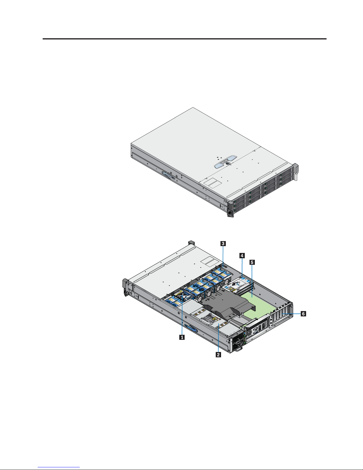
Figure 1 shows a front view of the Secure Managed Client (SMC) - Storage Array
while Figure 2 shows a rear view with the lid removed, showing those areas
accessible to service personnel only.
Figure 1. SMC - Storage Array front view
Figure 2. SMC - Storage Array rear view, showing service areas
1 SAS expander card
2 Power supply unit
3 Cooling fans (10)
4 Boot drive
5 Server board
6 PCI slots
© Copyright Lenovo 2005, 2008 3
Enclosure subsystem
The SMC - Storage Array design concept is based on an enclosure subsystem
together with a set of plug-in modules and (as supplied) consists of:
v An enclosure chassis with:
– A backplane PCB
– An enclosure management PCB
– A SAS expander PCB, to branch from 4 to 12 SAS ports, supporting SATA
tunnelling protocol
– A front operator's panel
– An integral rear panel, incorporating an enclosure ID LED
– A power supply mounting cage containing one 850-W plug-in power supply
unit (PSU)
Note:
A server subsystem comprising:
v
– An Intel Server Board S5000PSL with integral I/O panel
– An Intel RAID Controller SRCSATAWB
– A boot drive module
A cooling module containing 10 high-speed, single-rotor axial fans, which are
v
individually pluggable
v 12 SATA hard drives
A blanking plate must be installed over the empty upper bay.
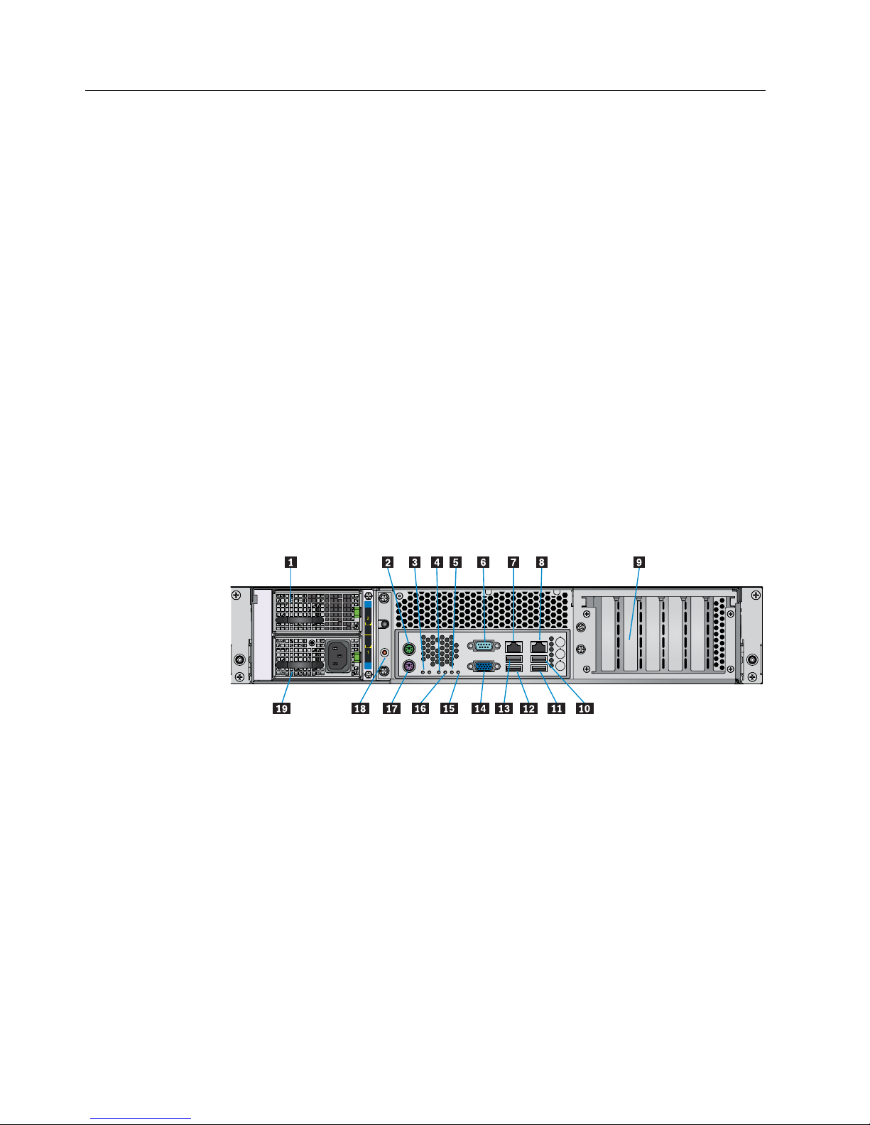
Figure 3. Enclosure subsystem rear view
1Empty power supply bay 11USB port 1
2PS2 mouse port 12USB port 3
3System status LED 13USB port 2
4MSB (POST LED) 14Video port
5Bit 1 (POST LED) 15LSB (POST LED)
6Serial port 16Bit 2 (POST LED)
7NIC port 1 (1 Gb) 17PS2 keyboard
8NIC port 2 (1 Gb) 18ID LED
92 dual-port Ethernet cards 19Power supply unit 1
10USB port 0
4 User Guide
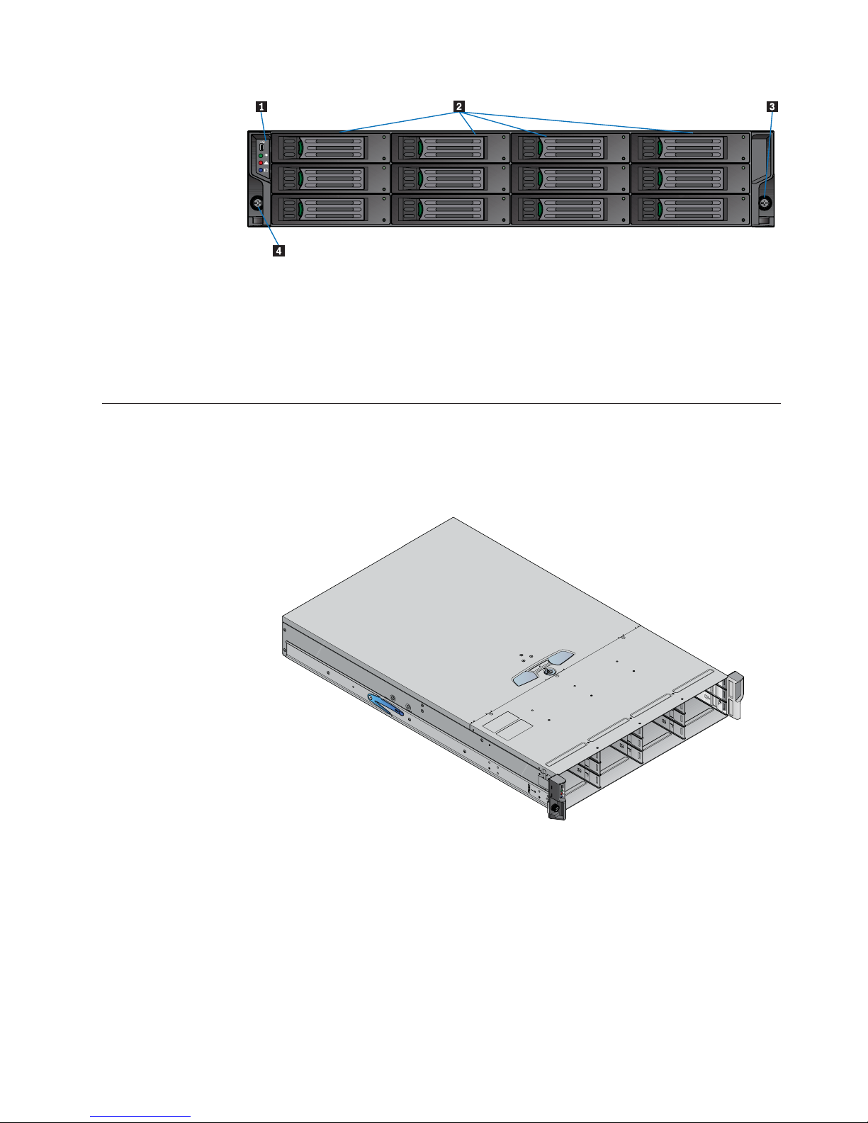
Figure 4. Enclosure subsystem front view
1Front panel
2Drive bays
3Rack retaining screw
4Rack retaining screw
Enclosure chassis
The chassis is installed with 48.26-cm (19-inch) rack-mounting features, which
enable it to be installed to standard 48.26-cm (19-inch) racks. One chassis occupies
two units of rack space (3.5 inches or 8.89 cm high).
Figure 5. Enclosure chassis
The backplane PCB provides 12 direct dock SAS/SATA connectors to the drives
and acts as the connectivity hub of the enclosure, connecting to the enclosure
management PCB.
The ten cooling fans are connected to the system by the enclosure management
PCB.
There are 12 drive bays at the front of the enclosure. Each drive bay accommodates
a plug-in drive carrier module that can house one low-profile 2.54-cm (1-inch) high
Chapter 2. Features 5
8.89-cm (3.5-inch) form factor drive. In addition, two 6.35-cm (2.5-inch) boot drives
can be installed in the boot drive module.
A bay is defined as the space required to house a single 2.54-cm (1.0-inch)
Note:
high 8.89-cm (3.5-inch) disk drive in its carrier module (limitation of 1 TB
size).
At the rear, the chassis assembly accommodates one PSU and a server board
subsystem.
A top cover on the enclosure provides access to the cooling fans and the server
board subsystem.
The enclosure cover should only be removed by qualified service personnel
Note:
as it provides access to a service area. Upon replacement, the cover MUST
be secured by tightening the lock mechanism to the locked position with a
screwdriver.
Figure 6. Locking the enclosure cover
Server board subdivision
The server board subdivision consists of:
v An Intel Server Board S5000PSL
v Slots for up to six low-profile 1.905-cm (3/4-inch) PCI cards, installed in a
vertical orientation. The following PCBs are installed as standard configuration:
– An Intel RAID Controller SRCSATAWB, in the left-hand slot (when viewed
from the rear)
v A boot drive module, which contains two 6.35-cm (2.5-inch) SATA boot drives
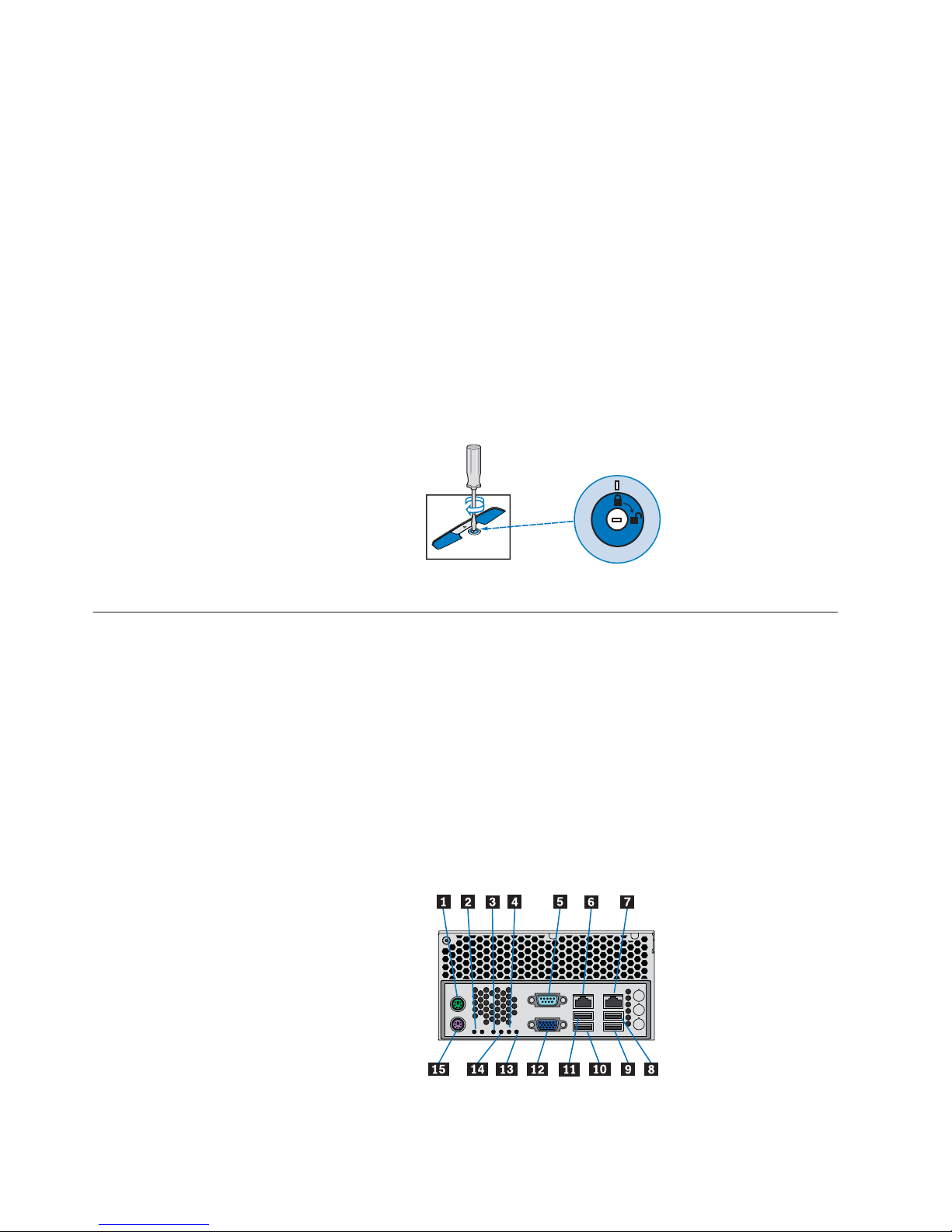
Server board I/O panel
The server board I/O panel consists of various connectors and LEDs.
Figure 7. Server board I/O panel connectors
6 User Guide

1PS2 mouse port 9Bit 2 (POST LED)
2System status LED 10LSB (POST LED)
3MSB (POST LED) 11Video port
4Bit 1 (POST LED) 12USB port 2
5Serial port 13USB port 3
6NIC port 1 (1 Gb) 14USB port 1
7NIC port 2 (1 Gb) 15USB port 0
8PS2 keyboard
Connectors
The following connectors are located on the server board I/O panel:
v PS2 mouse port
v PS2 keyboard port
v Serial port
v Video port
v Tw o RJ-45 ports - NICs 1 and 2 (1Gb each)
v Four USB ports: 0, 1, 2, and 3
Server board LEDs
Status LEDs: Diagnostic LEDs are located on the server board I/O panel to assist
in identifying failed and failing components. See “Server board LEDs” on page 25
for a summary of status LED states.
NIC LEDs: The NIC LEDs at the right and left of each NIC port provide
information on NIC status. See “I/O panel NIC LEDs” on page 25 for a summary
of NIC LED states.
Front operator's panel
A front operator ’s panel, consisting of a USB port, three LEDs and three
push-button switches, are located on the front of the enclosure.
The front operator’s panel is an integral part of the enclosure assembly and
Note:
is not field replaceable.
Figure 8. Front operator’s panel components
1USB port 5Power active LED
2Unit fault LED 6ID LED
Chapter 2. Features 7

Rear panel
3On/off switch 7Reset button (recessed)
4ID LED activation switch
Table 1. Functions of front operator's panel LEDs and switches
LED Push-button switch USB Port
Power Active (Green) Power On/Off Intended for service use only.
Unit Fault (Amber) Reset Button Intended for service use only.
Enclosure ID (Blue) Enclosure ID LED Activation Intended for service use only.
For a full description of LED and switch functions, see “Front operator's panel
LEDs and switches” on page 20.
A rear panel, consisting of a blue enclosure ID LED (see Figure 2 on page 3), is
located on the rear of the enclosure.
Note: The rear panel is an integral part of the enclosure assembly and is not field
replaceable.
Table 2. Rear Panel ID LED Status
Enclosure ID LED Blue (when activated) Activated by push button on
Power supply unit
AC-DC power is provided by a power supply with specific load capability,
mechanical packaging, and output connectors to suit this product.
A power supply mounting cage is installed in the rear of the enclosure as part of
the subsystem core product. The cage houses one individually hot pluggable
850-W AC power supply unit (PSU) with its own IEC inlet connector and failure
indicator.
the Front Operator's Panel,
or by system software.
Used to identify a server
from among several servers.
8 User Guide

Figure 9. Power supply unit
Power supply unit voltage operating ranges are nominally 100V - 240V AC,
selected automatically.
Power supply output connectors
Cooling fans
The PSU has an audible alarm to indicate a fault state and a bi-color (green/red)
LED to indicate PSU status.
The power supply output connectors provide the following outputs:
v P1 server board main power connector (1 x 24 pin)
v P2 processor power connector (8 pin)
v P3 12-V power connector
v P4 peripheral power connector (2 x 4 pin)
v P5 PSU1 connector (5 pin)
Ten high-speed single-rotor axial fans are housed in a cooling cage, located
centrally within the enclosure, between the drive bays and the server board, as
shown in Figure 2 on page 3. This ensures maximum airflow through the PSU and
minimizes noise.
Chapter 2. Features 9

Figure 10. Cooling fan
Airflow is front to rear with cooling air being drawn across the drives, through the
fans and pressurizing the rear of the enclosure. The pressurized rear allows the
PSU to draw the air that it requires; perforations at the rear of the chassis allow
cooling air to flow over the processor heatsinks, server board and PCI cards.
The cooling system must be operated with low-pressure rear exhaust installation
(back pressure created by rack doors and obstacles not to exceed 5 pascals [0.5mm
Water gauge]).
The cooling system provides sufficient capacity to ensure that drive maximum
temperatures have not exceeded at 35°C (95°F) with one failing fan at sea level.
The cooling cage contains ten individual high-speed single-rotor axial fans,
individually connected to and interfacing with the enclosure management PCB.
This interface provides power and speed control to the fans and returns speed
output from each fan to the management system.
Drive carrier module
The drive carrier module consists of a hard disk mounted in a drive carrier. Each
drive bay can house a single low-profile 2.54-cm (1.0-inch) high, 8.89-cm (3.5-inch)
form factor SATA disk drive in its drive carrier. The drive carrier has mounting
locations for SATA drives.
Each disk drive is enclosed in a sheet steel carrier which provides excellent thermal
conduction, radio frequency and electro-magnetic induction protection, as well as
affords the drive with maximum physical protection.
The front cap of the drive carrier supports an ergonomic handle, which provides
the following functions:
v Camming of drive carrier into and out of drive bays.
v Positive "spring loading" of the drive/backpane connector.
10 User Guide

Figure 11 . Driver carrier module
Drive status indicator
Disk drive status, under ESI processor control, is monitored by two LEDs (a green
LED and an amber LED) mounted on the front cap of each drive carrier module.
See “Disk drive LEDs” on page 21 for a description of LED states.
Figure 12. Drive status LEDs and components
1Green LED
2Amber LED
3Torque screw
4Drive lock indicator opening
Anti-tamper locks
Anti-tamper locks are installed in each drive carrier handle and are accessed with a
TORX screwdriver through the small cutout in the latch section of the handle.
When activated, the locks disable the normal "pinch" latch action of the drive
carrier handle. A drive is locked when the red lock symbol appears in the indicator
opening.
Chapter 2. Features 11

12 User Guide

Chapter 3. Getting Started
In this chapter, you are shown how to plan and install your Secure Managed Client
(SMC) - Storage Array into an industry standard 48.26-cm (19-inch) rack cabinet.
CAUTION:
When connecting the SMC - Storage Array, use only the power cords supplied or
power cords that match the specification quoted in the Safety and Warranty Guide.
Planning your installation
Before installing the SMC - Storage Array, familiarize yourself with the
configuration requirements listed in the following table.
CAUTION:
Installation procedures should be performed by trained personnel only.
Table 3. Configuration requirements
Module Location
Drive bays All drive bays must be installed with either
a drive carrier module or a dummy drive
carrier module. No bays should be left
empty. A minimum of 1 drive must be
installed.
Power supply One PSU can be installed. A blanking plate
must be installed to cover the empty (top)
slot.
Cooling fans Ten fans, housed in a cooling cage, are
located centrally within the enclosure
between the drive bays and the server
board.
PCI cards Up to six PCI cards can be installed in a
vertical orientation. Currently, only the two
outer card slots are used in the standard
configuration, installed with an Intel® RAID
Controller SRCSAS144E and an Intel
®
Intelligent AXXRIBBU1 Battery Backup Unit.
When not in use, the four empty PCI slots
must be installed with blanking plates.
Drive bay numbering convention
The drive bay numbering convention is as follows.
© Copyright Lenovo 2005, 2008 13

Figure 13. Drive bay numbering
The SMC - Storage Array subsystem is housed in a 4 x 3 enclosure (four drive bays
wide by three bays high). The top bays are numbered 1 to 4 from left to right, as
viewed from the front. Drive carrier module locations are identified from a matrix
of the top and side numbers.
Enclosure installation prerequisites
The SMC - Storage Array is delivered fully populated with 12 drive carrier
modules pre-installed.
Notes:
1. The SMC - Storage Array with all its component parts installed is too heavy for
a single person to easily install into a rack cabinet.
2. Ensure that you have fitted and checked a suitable anti-static wrist or ankle
strap and observe all conventional ESD precautions when handling modules
and components. Avoid contact with backplane, server board and PCI card
components and module connectors, or other parts. See the Safety and Warranty
Guide for additional information on static electricity prevention.
Preparation of site and host server
Before beginning, make sure that the site where you intend to set up and use your
SMC - Storage Array has standard AC power available from an independent
source or a rack power distribution unit with a universal power supply (UPS).
Unpacking the enclosure system
The package contents and unpacking procedure are outlined in the following
figure.
14 User Guide

Figure 14. Unpacking the SMC - Storage Array
Planning and configuring your installation
Refer to “Planning your installation” on page 13 for information on overall system
configuration requirements.
Refer to the Secure Managed Client (SMC) - Storage Array Setup Poster that shipped
with your system for instructions on installing the processors, drives, and memory.
Rack installation prerequisites
The SMC - Storage Array is designed for installation into an industry standard
48.26-cm (19-inch) cabinet capable of holding the unit.
v Minimum depth: 70.76 cm (27.83 inches) from rack posts to maximum extremity
of enclosure (excludes rear cabling).
v Weight: up to 30 kg (66.20 lb), dependent upon configuration, per enclosure.
v A minimum gap of 2.54-cm (1-inch) clearance is required between the rack cover
and front of drawer. A 5.08 cm (2-inch) rear clearance between rear of drawer
and rear of rack is recommended to maintain correct airflow around the
enclosure.
v The rack should present a maximum back pressure of 0.5 mm (5 pascals) water
gauge.
Chapter 3. Getting Started 15

CAUTION:
Operation of the enclosure system with any modules missing will disrupt the
airflow and the drives will not receive sufficient cooling. It is essential that all
openings are filled before operating the unit.
Installing the enclosure in a rack
A set of rack-mounting rails is provided with the system for installing the SMC Storage Array in a 48.26-cm (19-inch) rack cabinet. These rails have been designed
and tested to handle the maximum weight of the enclosure and to ensure that
multiple enclosures may be installed without loss of space within the rack. Use of
other mounting hardware may cause some loss of rack space.
Contact your supplier to ensure suitable mount rails are available for the rack you
are using.
Rail kit assembly
Refer to the Rail Kit Installation Guide for instructions on assembling the rail kit.
Figure 15. Rack mount rail kit
1Rear rack post
2Clamping screws
3Rack bracket ASM
4Front rack post
5Slide screw (4)
6Slide washer (4)
Enclosure installation
To install the enclosure, do the following:
1. Check for damage.
2. Lift enclosure and align with front rails.
3. Carefully insert enclosure slides into rack rails and push fully home.
4. Tighten rear screws.
5. Withdraw enclosure until it reaches hard stops (approximately 400 mm).
6. Tighten front screws.
16 User Guide

7. Return enclosure to fully home position and attach to rack using captive
fasteners on front flanges.
Rack rails have features to restrict complete enclosure withdrawal while still
Note:
allowing access to the cooling fans. If it becomes necessary to completely
remove the system, pull the enclosure out until it stops then rotate the
latches, shown in Figure 15 (right hand up, left hand down), to completely
remove the enclosure from the rack.
Power cord connection
CAUTION:
The power connection must always be disconnected prior to removal of a PSU
from the enclosure.
To connect the power cord, do the following:
1. Observe all safety and ESD precautions listed in the Safety and Warranty Guide.
2. Attach a power cord for the installed PSU. The Power On LED (see 1 in
Figure 16) for the PSU will blink green when AC main power is present. The
Power On LED will illuminate a constant green when power to the PSU is
turned on.
Figure 16. Connecting power cords
Grounding checks
The SMC - Storage Array must only be connected to a power source that has a
safety electrical earth connection.
CAUTION:
If more than one enclosure is installed in a rack, the earth connection to the rack
is even more important, because the rack will have a high “earth leakage
current” (“touch current”).
Before powering on, the earth connection to the rack must be checked by an
electrical engineer who is qualified in local and National electrical standards.
Chapter 3. Getting Started 17

18 User Guide

Chapter 4. Operation
Before powering on the Secure Managed Client (SMC) - Storage Array ensure that
all modules are firmly seated in their correct bays.
Power on
Apply AC main power to power on the enclosure.
The power active LED on the front operator ’s panel will light up green once
power is activated. The disk drive motors will also start running.
CAUTION:
Do not operate the SMC - Storage Array until the ambient temperature is within
the specified operating range. If the drives have been recently installed, ensure
they have had time to acclimate before operating them.
Notes:
1. If main power is lost for any reason, upon restoration of power, the enclosure
will re-start automatically.
2. See “Front operator's panel LEDs and switches” on page 20 for details on Front
Operator’s Panel LEDs and related fault conditions.
Power supply unit LED
The PSU has a bi-color red/green LED.
v When the PSU is connected to a main supply, the LED will flash green.
v When the PSU is switched on, the LED will illuminate a constant green.
v If a fault occurs, the LED will illuminate a constant red.
v If an over-current, under-voltage or over-voltage protection condition occurs, the
LED will flash red.
Figure 17. Power supply unit LEDs
© Copyright Lenovo 2005, 2008 19
1POST LED

Front operator's panel LEDs and switches
The front operator’s panel LED fault and status conditions are defined in Table 4.
Functions of the push-button switches are defined in Table 5.
Figure 18. Front operator’s panel components
1USB port
2Power active LED
3Unit fault LED
4ID LED
5On/off switch
6Reset button (recessed)
7ID LED activation switch
Table 4. Front operator's panel LED states
LED Status
Power active Constant green: good or positive indication
Unit fault Constant amber: fault present
Enclosure ID Blue: only when activated
Table 5. Front operator's panel switch functions
Push-button
switch Definition
On/Off Function of this button is dependent on the enclosure status.
Enclosure connected to power source but not operating.
Press button to activate and commence boot process.
Enclosure operating: Depress button for <4 seconds to turn off
the enclosure.
System reset Resets the enclosure hardware and firmware.
This button is recessed and is activated with a ball-point pen or similar
implement.
Enclosure ID Each press of this button causes the state of the blue ID LED on the Front
Operator's Panel and rear panel to change.
20 User Guide

Starting the drives
Unless otherwise selected during installation, all drives in the enclosure should
automatically start their motors during power on. If this does not occur then one
of the following conditions may exist:
v There may be a power problem (an alarm and power fault indication would
normally be present).
v The drive motors will spin up in a delayed sequence.
Disk drive LEDs
Each drive carrier module has two LEDs, an upper (green) LED and a lower
(amber) LED.
v During normal operation, the green LED will be on and will flicker to indicate
drive activity. It will also be on when no drive is present. It is off when the drive
is not spun up.
v During normal operation, the amber LED will be:
– Off if no drive is present
– Off as the drive operates
– On if a drive fault exists
Engaging the drive module anti-tamper locks
An anti-tamper lock is installed in each drive carrier handle and can be accessed
through the small cutout in the latch section of the handle with a TORX
screwdriver. A lock symbol displays in the small opening beside the torque screw
when the drive is locked.
Activating an anti-tamper lock
To activate an anti-tamper lock, do the following:
1. Carefully insert the TORX screwdriver provided into the cutout in the handle
(see 1 in Figure 19).
2. Rotate the screwdriver in a clockwise direction until the lock symbol is visible
in the opening beside the key see 2 in Figure 19).
Note: Do not turn the lock more than half a turn; otherwise, the drive carrier
may be damaged.
3. Remove the screwdriver.
Figure 19. Activating an anti-tamper lock
Note: A drive carrier cannot be installed if its anti-tamper lock is activated outside
the enclosure.
Deactivating an anti-tamper lock
To deactivate an anti-tamper lock, do the following:
Chapter 4. Operation 21

BIOS settings
1. Carefully insert the TORX screwdriver provided into the cutout in the handle
(see 1 in Figure 20).
2. Rotate the screwdriver in an anti-clockwise direction until the lock symbol is no
longer visible in the opening beside the key (see 2 in Figure 20).
Do not turn the lock more than half a turn; otherwise, the drive carrier
Note:
may be damaged.
3. Remove the screwdriver.
Figure 20. Deactivating an anti-tamper lock
To install the AMI StorTrends iTX software, verify the following BIOS settings:
1. Disable the Onboard SATA Controller option to install onto the boot drive. This
option is present in the ATA Controller Configuration settings under the
Advanced tab.
2. Enable the LSI MPT SAS Controller option, which is present in the Mass
Storage Controller Configuration settings under the Advanced tab.
3. If you add DIMMS to increase system memory, the default BIOS option limits
the memory visible to the operating system to 2.50GB. To make more memory
visible to the operating system, modify the Memory Mapped I/O Start Address
option, which is present in the PCI Configuration settings under the Advanced
tab.
4. To boot from the network using PXE boot, enable the option Onboard NIC
ROM option, which is also present in the PCI Configuration settings. The
device boot order registers this change after you save the changes and reboot.
5. To boot from the boot drive attached to the LSI MPT SAS controller, change the
hard disk order under the Boot Options tab. Set ID01 LUN0 as the first disk,
followed by the PCI RAID adapter. If you need to enable the network boot,
select IBA GE as the first boot device.
6. To boot from the boot drive attached to the LSI MPT SAS controller, set ID01
LUN0 as the second boot option under the Boot Options tab.
The drives need to be connected to the blue S ATA slots on the server
Note:
Turning off
To turn off the enclosure, either:
v Turn off the PSU installed in the enclosure by pressing the power push-button
on the front operator's panel for approximately three seconds,
OR
v Remove AC main at the power source
22 User Guide
board for installation.

Chapter 5. Troubleshooting and problem solving
The Secure Managed Client (SMC) - Storage Array includes an enclosure services
processor and associated monitoring and control logic to enable it to diagnose
problems within the enclosure’s power, cooling and drive systems.
The sensors for power and cooling conditions are housed within the PSUs and
cooling fans. There is independent monitoring for each unit.
Initial start-up problems
The following problems may occur on initial start up:
Faulty cords
First check that you have wired up the subsystem correctly. Call your supplier for
replacement if:
v Cords are missing or damaged.
v Plugs are incorrect.
v Cords are too short.
LEDs
Alarm sounds and power up
See “Audible alarms” on page 26 for details.
Computer doesn't recognize the subsystem
1. Check that the interface cables from the SMC - Storage Array to the host
computer are installed correctly.
2. Check that the LEDs on all installed drive carrier modules are illuminated
(amber).
Note: Drive LEDs will not be lit during drive spin up.
3. Check that drive carrier modules have been correctly installed.
A green LED is always used for good or positive indication. A flashing
green/amber LED is used for non-critical conditions. With the exception of the
drive carrier module LED, which is lit amber under Normal conditions (see “Drive
carrier module faults” on page 30), a continuous red or amber LED indicates the
presence of a critical fault within the module.
Power supply units
The power supply unit provides a single external bi-color LED to indicate the
status of the power supply. When AC is applied to the PSU and standby voltages
are available, the LED will blink green. The LED will be solid on green to indicate
that all power outputs are available. The LED will be on solid amber to indicate
that the power supply has failed (shut down due to over current, shut down due
to over temperature, or a predictive failure).
© Copyright Lenovo 2005, 2008 23

Table 6. Power supply unit LED states
Condition LED state
No AC power to all PSUs Off
Power supply direct current (DC) outputs
Green
ON and OK
No AC power to this PSU only Amber
AC present / only standby outputs Blink Green
Power supply failure (includes over voltage,
Amber
over temperature)
Voltage regulator module (VRM) failure
Blink green
(cage related)
240VA limit (cage related) Blink green
Current limit Amber
Front operator's panel
The front operator’s panel displays the aggregated status of all the modules. Front
operator’s panel LED states are defined in Table 4 on page 20.
Note: The front operator’s panel is supplied as an integral part of the enclosure
core product and is not user replaceable.
Figure 21. Front operator’s panel LEDs
1Power active LED
2Unit fault LED
3Enclosure ID LED
Table 7. Ops panel LED states
LEDs Normal Operation Fault condition
Power active Constant green: good or
positive indication
Unit fault Off Constant amber: fault present
Enclosure ID Blue: only when activated Blue: only when activated
24 User Guide

Cooling fan LEDs
An amber LED incorporated in each cooling fan monitors its status. Constant On
indicates a fault condition. .
Drive carrier module LEDs
Disk drive status is monitored by a green LED and an amber LED mounted on the
front of each drive carrier module. The conditions for each LED are defined in
“Drive carrier module faults” on page 30.
Rear panel LED
Table 8. Rear panel status LED
Enclosure ID LED Blue (when activated) Activated by push button on
the front operator's panel, or
by system software. Used to
identify a server from among
several servers.
Server board LEDs
Server board LEDs consist of I/O panel status LEDs and I/O panel NIC LEDs.
I/O panel status LEDs
The server board I/O panel contains a number of diagnostic LEDs, whose
functions are summarized in the following table. Refer to your server board
documentation for full details of each LED state.
Table 9. Server board status LEDs
LED Color Function
System status LED
v Green
v Off
v Alternating green/amber
v Amber
v Green blink
v Amber blink
v System OK
v AC power off
v System not ready
v Critical fault
v System degraded
v Non-fatal alarm, system
likely to fail
4 x power-on self test (POST)
LEDs
Off
*Amber
System running normally
The POST LEDs toggle
between red, green, amber,
and Off at boot up.
*(Lit amber only if a
failure occurs)
I/O panel NIC LEDs
The Network Interface Controller (NIC) LED states are summarized in the
following table. Refer to your server board documentation for full details of each
state.
Chapter 5. Troubleshooting and problem solving 25

Audible alarms
Table 10. NIC LEDs
LED LED state Description
Left Off No network connection is in
place
Solid green Active network connection is
in place
Blinking green Transmit / receive activity is
occurring
Right Off 10 Mbps connection (if left
LED is on or blinking)
Solid green 100 Mbps connection
Solid amber 1000 Mbps connection
The PSUs incorporate audible alarms, which indicate when a fault state is present.
A Voltage Out Of Range condition will activate the audible alarm.
The audible alarm can be muted by pressing the Enclosure ID button on the front
operator’s panel.
Alarm interpretation
The following table summarizes the various interpretations when combining LED
states and audible alarms. Use this table to help understand a pattern of lights and
beeps. Each light/beep is taken in turn and shows linked items, so some of the
data is duplicated in several places to make ease of search better.
Note: There will be no beep if the enclosure is muted.
Table 11. Light and buzzer interpretations
LED/buzzer State Related Meaning Action
Front operator's panel
fault light
Off - No warnings or
worse
Slow blink (0.5
seconds on, 3.5
seconds off)
Slow beep (half
second beep every
8 seconds). No fan/
drive lights lit
Warning state usually approaching
temperature
threshold.
constant. No beep if
muted.
Slow beep. Fan light
constant. No beep if
Fan broken or out of
tolerance.
muted.
Slow beep. Fan light
Drive fault Replace drive
constant. No beep if
muted.
None - all OK
Check ambient
temperature and
increase if too cold or
decrease if too hot. If
this does not work,
check for fan failure
that has a broken
light, too.
Replace lit fan.
26 User Guide

Table 11. Light and buzzer interpretations (continued)
LED/buzzer State Related Meaning Action
Fast blink (alternating
every half second)
Faster beep (1.5
seconds beep, 0.5
seconds silence). No
fan light constant.
No beep if muted.
Critical state - usually
temperature near
edge of operating
range
Check ambient
temperature and
increase if too cold or
decrease if too hot
immediately. If this
does not work, check
for a fan failure that
also has a broken
light.
Faster beep, more
than one fan light
Fans broken or out of
tolerance.
Replace fans
immediately.
on or a single PSU
fan light on. No
beep if muted.
Constant on Constant - no fan
lights lit constant
Failure state temperature in range
where damage could
occur
Check ambient
temperature and
increase if too cold or
decrease if too hot
immediately. If this
does not work check
for fan failure that
has a broken light,
too.
Constant - multiple
fan lights lit constant
Fans broken or out of
tolerance
Replace fans
immediately. Decrease
ambient temperature
Fan light Constant on Varying levels of
beep and chassis
Fan broken or out of
tolerance.
Replace fans
immediately.
fault light setting.
No beep if muted.
Drive light (amber) Constant on Varying levels of
beep and chassis
Drive faulty Replace drive
fault - usually slow
beep and slow flash.
No beep if muted.
Front operator's panel
Flashing Ops panel ident on
ID LED
Buzzer Off Front operator's panel
No issues
fault LED off
Off Front operator's panel
fault LED flashing or
constant
Intermittent short
beep (0.5 second beep
every 32 seconds)
Various front
operator's panel fault
light flash states
Muted See Table 4 on page
20 for interpretation
of lights and remedy.
Fault has occurred
and system is muted
but in remind mode
Check fault status
using ops panel fault
LED settings and
remedy.
Slow beep (half
second beep every 8
seconds)
Front operator's panel
fault LED slow blink
(0.5 seconds on, 3.5
Warning mode See Table 4 on page
20.
seconds off)
Chapter 5. Troubleshooting and problem solving 27

Table 11. Light and buzzer interpretations (continued)
LED/buzzer State Related Meaning Action
Faster beep (1.5
seconds beep, 0.5
second silence)
Front operator's panel
fault LED fast blink
(alternating every half
Critical mode See Table 13.
second)
Constant beep Front operator's panel
fault LED constant on
Failure mode See Table 4 on page
20.
Troubleshooting
The following sections describe common problems, with possible solutions, which
can occur with your Secure Managed Client (SMC) - Storage Array.
For details on how to remove and replace a module see the Hardware Installation
and Replacement Guide.
System faults
Table 12. System faults
Symptom Cause Action
1. Audible alarm sounds 1. Internal fault detected (failure of
an internal communications path)
1. Check for other amber LED
indications of the power supply
units. If there is a PSU error
present there may be a
communication problem with that
PSU. Remove and then re-install
the PSU. If the problem persists
then change the PSU.
Power supply unit faults
Table 13. Power supply unit faults
Symptom Cause Action
1. Front operator's panel unit fault
LED amber
2. Audible alarm sounding
1. Any power fault
2. A thermal condition which could
cause PSU overheating
1. Check that the AC main
connection to PSU is live
2. Disconnect the PSU from main
power and remove the PSU from
the power supply cage. Re-install.
If problem persists, replace PSU.
3. Reduce the ambient temperature
28 User Guide

Cooling fan faults
Table 14. Cooling fan faults
Symptom Cause Action
1. Front panel fault LED amber
2. Audible alarm sounding
3. Fan LED is illuminated
1. Any power fault
2. A fan failure
1. Check to ensure DC power to
cooling fans is correct and that
the LED is not illuminated
2. Disconnect the PSU from main
power and remove the faulty fan
from the system. Re-install. If
problem persists, replace PSU.
3. Reduce the ambient temperature
Thermal cooling
The Secure Managed Client (SMC) - Storage Array uses extensive thermal
monitoring to ensure component temperatures are kept low and acoustic noise is
minimized. Airflow is from front to rear of the enclosure.
Table 15. Thermal cooling
Symptom Cause Action
If the ambient air is cool
(below 25°C or 77°F) and the
fans are observed to increase
in speed then some restriction
on airflow may be causing an
additional internal temperature
rise.
Note: This is not a fault condition.
The first stage in the thermal
control process is for the fans
to automatically increase in
speed when a thermal threshold
is reached. This may be caused
by higher ambient temperatures
in the local environment and may
be perfectly normal.
Note: This threshold changes
according to the number of drives
and power supplies installed.
1. Check the installation for any
airflow restrictions at either the
front or rear of the enclosure. A
minimum gap of 2.5 cm (1 inch)
at the front and 5 cm (2 inches) at
the rear is recommended.
2. Check for restrictions due to dust
build up; clean as appropriate.
3. Check for excessive re-circulation
of heated air from rear to front.
Use in a fully enclosed rack
installation is not recommended.
4. Check that all blank modules are
in place.
5. Reduce the ambient temperature.
Chapter 5. Troubleshooting and problem solving 29

Table 15. Thermal cooling (continued)
Symptom Cause Action
1. Front operator's panel unit fault
LED amber.
2. An amber LED is lit on one or
more PSUs.
If the internal temperature
measured in the airflow
through the enclosure
exceeds a pre-set threshold,
a thermal alarm sound.
1. Check to ensure that local
ambient environment temperature
is below the upper 35°C (95°F)
specification.
2. Check the installation for any
airflow restrictions at either the
front or rear of the enclosure. A
minimum gap of 2.5 cm (1 inch)
at the front and 5 cm (2 inches)
mm at the rear is recommended.
3. Check for restrictions due to dust
build up; clean as appropriate.
4. Check for excessive re-circulation
of heated air from rear to front.
Use in a fully enclosed rack
installation is not recommended.
5. If possible, turn off the enclosure
and investigate the problem
before continuing.
Drive carrier module faults
Each Drive Carrier module has two LEDs: an upper (green) LED and a lower
(amber) LED.
v Under normal operation, the green LED is on and will flicker as the drive
operates
v Under normal operation, the amber LED will be:
– Off if there is no drive present
– Off as the drive operates
– On if a drive fault is present
Dealing with hardware faults
Ensure that you have obtained a replacement module of the same type before
removing any faulty module.
v If the subsystem is powered up and you remove any module, replace it
immediately. If the subsystem is used with modules or module blanks missing
for more than a few minutes, the enclosure can overheat, causing power failure
and data loss. Such use will invalidate the warranty.
v Replace a faulty drive with a drive of the same type and equal or greater
capacity.
v Refer to your vendor-supplied documentation when using storage software for
handling drive-related hardware faults.
v All drive bays must be installed with a drive carrier module in order to
maintain a balanced airflow.
v All the supplied plug-in power supply units, electronics modules and blank
modules must be in place for the air to flow correctly around the cabinet
30 User Guide

CAUTION:
Observe all conventional ESD precautions when handling modules and
components. Avoid contact with backplane components and module connectors,
etc.
The top cover of the enclosure covers a service area which should be
Note:
accessed only by qualified service personnel. When the cover is replaced it
must be secured by turning the lock mechanism to the locked position.
Continuous operation during replacement
Depending on how the enclosure system is set up, if a disk unit fails, it can
normally be replaced without interrupting the use of the system.
Chapter 5. Troubleshooting and problem solving 31

32 User Guide

Chapter 6. Notices
Lenovo may not offer the products, services, or features discussed in this
document in all countries. Consult your local Lenovo representative for
information on the products and services currently available in your area. Any
reference to an Lenovo product, program, or service is not intended to state or
imply that only that Lenovo product, program, or service may be used. Any
functionally equivalent product, program, or service that does not infringe any
Lenovo intellectual property right may be used instead. However, it is the user’s
responsibility to evaluate and verify the operation of any other product, program,
or service.
Lenovo may have patents or pending patent applications covering subject matter
described in this document. The furnishing of this document does not give you
any license to these patents. You can send license inquiries, in writing, to:
Lenovo (United States), Inc
1009 Think Place
Building One
Morrisville, NC 27560
USA
Attention: Lenovo Director of Licensing
LENOVO GROUP LTD. PROVIDES THIS PUBLICATION “AS IS” WITHOUT
WARRANTY OF ANY KIND, EITHER EXPRESS OR IMPLIED, INCLUDING, BUT
NOT LIMITED TO, THE IMPLIED WARRANTIES OF NON-INFRINGEMENT,
MERCHANTABILITY OR FITNESS FOR A PARTICULAR PURPOSE. Some
jurisdictions do not allow disclaimer of express or implied warranties in certain
transactions, therefore, this statement may not apply to you.
This information could include technical inaccuracies or typographical errors.
Changes are periodically made to the information herein; these changes will be
incorporated in new editions of the publication. Lenovo may make improvements
and/or changes in the product(s) and/or the program(s) described in this
publication at any time without notice.
The products described in this document are not intended for use in implantation
or other life support applications where malfunction may result in injury or death
to persons. The information contained in this document does not affect or change
Lenovo product specifications or warranties. Nothing in this document shall
operate as an express or implied license or indemnity under the intellectual
property rights of Lenovo or third parties. All information contained in this
document was obtained in specific environments and is presented as an
illustration. The result obtained in other operating environments may vary.
Lenovo may use or distribute any of the information you supply in any way it
believes appropriate without incurring any obligation to you.
Any references in this publication to non-Lenovo We b sites are provided for
convenience only and do not in any manner serve as an endorsement of those Web
sites. The materials at those We b sites are not part of the materials for this Lenovo
product, and use of those Web sites is at your own risk.
© Copyright Lenovo 2005, 2008 33

Trademarks
Any performance data contained herein was determined in a controlled
environment. Therefore, the result in other operating environments may vary
significantly. Some measurements may have been made on development-level
systems and there is no guarantee that these measurements will be the same on
generally available systems. Furthermore, some measurements may have been
estimated through extrapolation. Actual results may vary. Users of this document
should verify the applicable data for their specific environment.
The following terms are trademarks of Lenovo in the United States, other
countries, or both:
Lenovo
the Lenovo logo
Microsoft, Windows, Windows Vista, and Active Directory are trademarks or
registered trademarks of Microsoft Corporation in the United States, other
countries, or both.
Other company, product, or service names may be trademarks or service marks of
others.
34 User Guide


Part Number: 45K1342
Printed in USA
(1P) P/N: 45K1342
 Loading...