

Lenovo S9 User Manual

Lenovo
IdeaPad
S9/S10
User Guide V2.0

Note
Before using this information and the product it supports, be sure to read the following:
• Chapter 6. Safety, use, and care information on page 59.
• Appendix D. Notices on page 124.
• OneKey Rescue System User Guide included in the package with this publication.
Second Edition (February 2009)
© Copyright Lenovo 2009. All rights reserved.
U.S. GOVERNMENT USERS – RESTRICTED RIGHTS: Our products and/or services are provided with
RESTRICTED RIGHTS. Use, duplication or disclosure by the Government is subject to the GSA ADP Schedule
contract with Lenovo, if any, or the standard terms of this commercial license, or if the agency is unable to accept
this Program under these terms, then we provide this Program under the provisions set forth in Commercial
Computer Software–Restricted Rights at FAR 52.227-19, when applicable, or under Rights in Data-General, FAR
52.227.14 (Alternate III).

ENERGY STAR model information
ENERGY STAR® is a joint program of the U.S. Environmental Protection
Agency and the U.S. Department of Energy aimed at saving money and
protecting the environment through energy efficient products and practices.
Lenovo® is proud to offer our customers products with an ENERGY STAR
compliant designation. Lenovo computers of the following machine types, if
the ENERGY STAR mark is affixed, have been designed and tested to conform
to the ENERGY STAR 4.0 program requirements for computers.
• 20013, 20015
• 4067, 4231
By using ENERGY STAR compliant products and taking advantage of the
power-management features of your computer, you reduce the consumption of
electricity. Reduced electrical consumption contributes to potential financial
savings, a cleaner environment, and the reduction of greenhouse gas emissions.

For more information about ENERGY STAR, visit
http://www.energystar.gov
.
Lenovo encourages you to make efficient use of energy an integral part of
your day-to-day operations. To help in this endeavor, Lenovo has preset
the following power-management features to take effect when your
computer has been inactive for a specified duration:
Table 1. ENERGY STAR power-management features, by operating system
Windo ws® XP
•Turn off monitor: After 10 minutes
•Turn off hard disks: After 30 minutes
•System standby: After 20 minutes
•System hibernates: After 2 hours
To awaken your computer from system standby mode, press any key on
your keyboard. For more information about these settings, refer to your
Windows Help and Support information system.

Explanation of Hard Disk Capacity
Dear user,
While using your computer, you may discover that the nominal hard disk
capacity indicated is somewhat different from the disk capacity
displayed by the operating system. For example, a nominal 80GB hard
disk will appear as less than 80GB in the operating system. This
discrepancy is not an error in hard disk installation nor any other
problem, but a normal phenomenon of computers. This phenomenon is
primarily due to the following reasons:
I. Different standards used by the manufacturer and operating
system when calculating hard disk capacity
Hard disk manufacturers use a radix of 1000, i.e. 1G = 1,000MB, 1MB =
1,000KB, 1KB = 1,000 bytes. However, when identifying hard disk capacity,
operating systems use a radix of 1024, i.e. 1GB = 1,024MB, 1MB = 1,024KB,
1KB = 1,024 bytes. The standard adopted by your computer is that of the
hard disk manufacturers. Since the standards adopted by the hard disk
manufacturer and operating system are different, the hard disk capacity
displayed by the operating system will be different from the nominal hard
disk capacity.
For example, if the hard disk is nominally X G, even when it is completely
empty, the capacity displayed by the operating system will be:
X × 1000 × 1000 × 1000/ (1024 × 1024 × 1024) ≈ X × 0.931 G

If a portion of the hard disk space has been used for some specific purpose,
then the capacity indicated by the operating system will be even less than
X × 0.931 G.
II. A portion of the hard disk space is used for specific purposes
Lenovo computers come with preinstalled OneKey Rescue System, so the
hard disk has a special portion partitioned before delivery, which is used to
store hard disk mirror and OneKey Rescue System program files. The size
of the reserved space for this partition varies according to the model,
operating system and software of the computer. For the sake of safety, this
partition is not evident, which is commonly referred to as a “hidden
partition”.
In addition, after the hard disk is partitioned or formatted, the system will
assign a certain amount of hard disk space for the system files.
For the above reasons, the available hard disk space indicated by the
operating system is always less than the computer’s nominal hard disk
capacity.

Contents
Chapter 1. Getting to know your
computer ....................................... 1
Top view........................................1
Left-side view................................3
Right-side view.............................4
Front view......................................5
Bottom view..................................6
Chapter 2. Using your
computer ....................................... 8
Putting your computer to standby
or shutting it down.......................8
Using the touchpad....................10
Using the keyboard....................11
Using memory cards (purchased
separately) ...................................15
Using the integrated camera .....16
Using the Internet.......................17
Securing your computer............25
Installing device drivers............31
Using battery and AC
adapter.........................................31
Chapter 3. Using external
devices.........................................36
Connecting a universal serial bus
(USB) device................................36
Connecting an ExpressCard/34
device (specific models only)....38
Connecting an external
display..........................................39
Connecting a headphone and
audio device ................................40
Connecting an external
microphone..................................41
Connecting to Bluetooth enabled
devices..........................................42
Chapter 4. Troubleshooting .......43
Frequently asked questions ......43
Troubleshooting..........................45
Chapter 5. Getting help and
service..........................................54
Getting help and service............54
Getting help on the Web............55
Calling the customer support
center............................................55
Getting help around the
world ............................................58
i

Contents
Chapter 6. Safety, use, and care
information.................................. 59
Important safety information... 59
Caring your computer...............78
Accessibility and comfort .........86
Maintenance................................ 89
Chapter 7. Using Linpus Linux
Lite............................................... 93
Using Linpus Linux Lite ........... 93
Appendix A. Lenovo Limited
Warranty.................................... 107
Warranty information .............115
Lenovo warranty service
telephone numbers ..................119
Appendix B. Customer replaceable
units (CRUs).............................. 121
Appendix C. Specifications ..... 122
Specifications............................122
ii
Appendix D. Notices .................124
Notices .......................................124
Wireless related
information................................127
Electronic emissions notices ... 129
WEEE and recycling
statements..................................135
EU WEEE Statements ..............136
Japan Recycling Statements.... 137
Notice for Users in the
U.S.A. .........................................139
Notice on deleting data from your
hard disk....................................139
Trademarks ...............................141
Index...........................................142
Chapter 1. Getting to know your computer
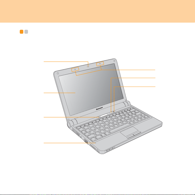
Top vi ew - - - - - - - - - - - - - - - - - - - - - - - - - - - - - - - - - - - - - - - - - - - - - - - - - - - - - - - - - - - - - - - - - - - - - - - - - - - - - - - - - - - - - - - - - - -
a
g
e
f
b
c
d
* The illustrations in this manual may differ from the actual product.
Please refer to the actual product.
1

Chapter 1. Getting to know your computer
Integrated camera............................................................................ 16
Computer display
The color display with LED-backlit technology provides clear and
brilliant text and graphics.
Power button
Use the power button to turn on the computer.
Microphone (built-in)
The built-in microphone (with noise reduction) can be used for video
conferencing, voice narration, or simple audio recordings.
OneKey™ Rescue System button (for Windows XP users
only) .................................................................................................. 14
Integrated wireless device button
Use this button to enable/disable the wireless radio of all the integrated
wireless devices on your computer.
Wireless antennae (built-in)
Depending on your model, at least one set of antenna are built into the
display for optimized reception.
2
Chapter 1. Getting to know your computer
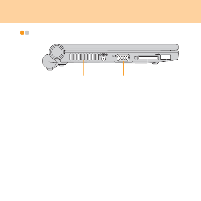
Left-side view - - - - - - - - - - - - - - - - - - - - - - - - - - - - - - - - - - - - - - - - - - - - - - - - - - - - - - - - - - - - - - - - - - - - - - - - - - - - - -
a
Fan louvers
The fan louvers allow warm air to exit the computer.
Important:
Make sure that paper, books, clothing, cables or other objects do not block
any of the fan louvers or else overheating of the computer may occur.
AC power adapter jack
Connect the power adapter here to supply power to the computer and
charge the battery pack.
Note:
To prevent damage to the computer and battery pack, use the supplied
AC adapter only.
VGA port ........................................................................................... 39
Memory card slot ............................................................................. 15
USB 2.0 port ..................................................................................... 36
b
d
ec
3
Chapter 1. Getting to know your computer
c
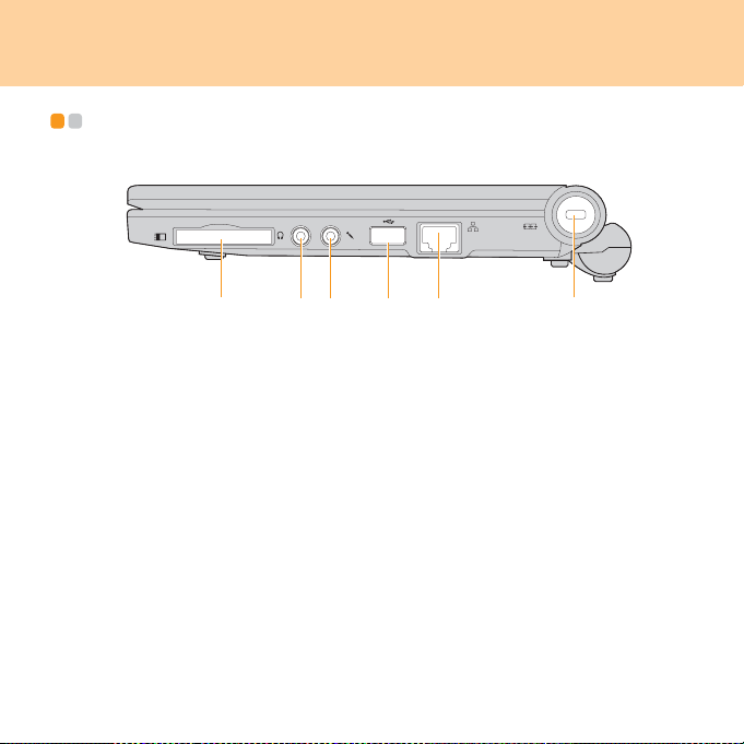
Right-side view - - - - - - - - - - - - - - - - - - - - - - - - - - - - - - - - - - - - - - - - - - - - - - - - - - - - - - - - - - - - - - - - - - - - - - - - - -
a
ExpressCard® slot (specific models only)..................................... 38
Headphone jack ............................................................................... 40
Microphone jack ............................................................................... 41
USB 2.0 port ..................................................................................... 36
LAN port............................................................................................ 17
Security keyhole
Your computer comes with a security keyhole. You can purchase a
security cable and lock to fit this keyhole.
Note:
Before purchasing any security product, verify that it is compatible with
this type of security keyhole.
b
e
fd
4
Chapter 1. Getting to know your computer
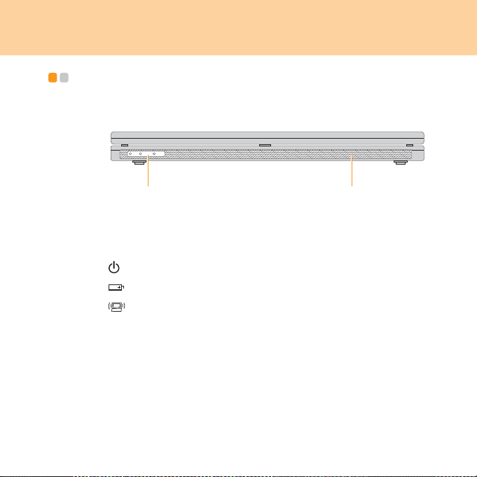
Front view - - - - - - - - - - - - - - - - - - - - - - - - - - - - - - - - - - - - - - - - - - - - - - - - - - - - - - - - - - - - - - - - - - - - - - - - - - - - - - - - - - - - - - -
ab
System status indicators
The system status indicators show the current status of your computer.
Power indicator
Battery status indicator
Wireless radio status indicator
Speakers
Built-in speakers for rich powerful sound.
* The above illustration may differ from the actual product. Please refer to
the actual product.
5
Chapter 1. Getting to know your computer
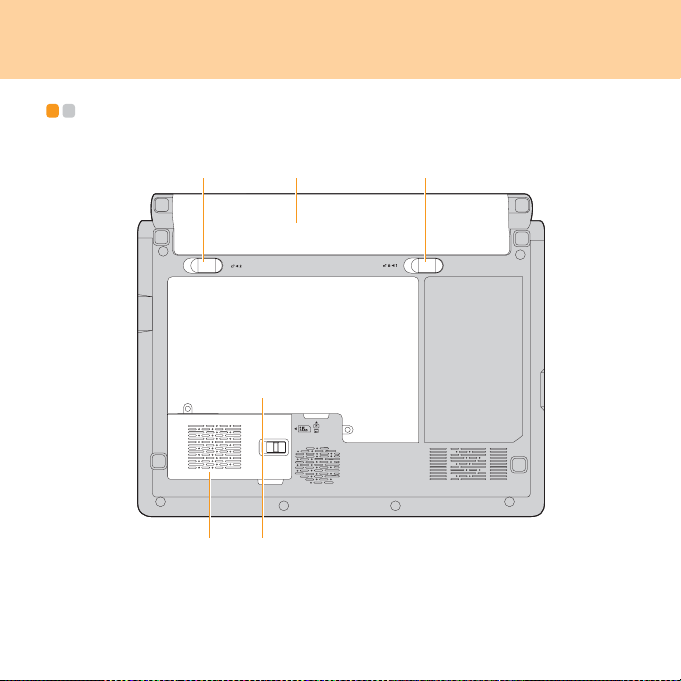
Bottom view - - - - - - - - - - - - - - - - - - - - - - - - - - - - - - - - - - - - - - - - - - - - - - - - - - - - - - - - - - - - - - - - - - - - - - - - - - - - - - - - - -
ba
e
d
* The above illustration may differ from the actual product. Please
refer to the actual product.
c
6

Chapter 1. Getting to know your computer
Battery latch - spring loaded
The spring-loaded battery latch keeps the battery pack secured in
place. When you insert a battery pack, this latch automatically secures
the battery in place. To remove the battery, hold this latch in the
unlocked position.
Battery pack ..................................................................................... 34
Battery latch - manual
The manual battery latch is used to keep the battery pack secured.
Move the manual battery latch to the unlocked position to insert or
remove the battery pack. Move the manual latch to the locked position
after inserting the battery pack.
Expansion slot compartment (specific models only)
The Mobile Broadband module is secured in this compartment.
Hard disk drive/Memory (RAM) compartment
7

Chapter 2. Using your computer
Note:
Some instructions in this chapter (such as “Putting your computer to
standby or shutting it down” and “OneKey™ Rescue System button”) are
only for Windows XP users.
If you are using the Linpus Linux Lite operating system, see “Using Linpus
Linux Lite” in Chapter 7.
Putting your computer to standby or shutting it down - - - - - -
When you finish working with your computer, you can put it to standby or
shut it down.
Putting your computer to standby
If you will be away from your computer for only a short time, put the
computer to standby.
When the computer is in standby, you can quickly wake it and bypass the
startup process.
To put the computer to standby, do one of the following.
Click Start and select Stand By from Turn Off Computer.
Press Fn + F1.
8

Chapter 2. Using your computer
Warning:
Wait until the power indicator light starts blinking (indicating that the
computer is in standby) before you move your computer. Moving your
computer while the hard disk is spinning can damage the hard disk,
causing loss of data.
To wake the computer, press the power button.
Shutting down your computer
If you are not going to use your computer for a day or two, shut it down.
To shut down your computer, click Start and select Tu rn Of f from Turn Off
Computer.
9
Chapter 2. Using your computer
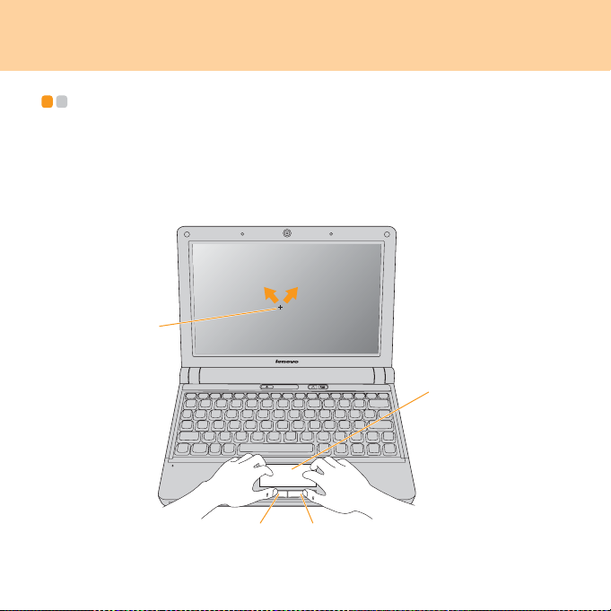
Using the touchpad - - - - - - - - - - - - - - - - - - - - - - - - - - - - - - - - - - - - - - - - - - - - - - - - - - - - - - - - - - - - - - - - - - - - -
The touchpad consists of a pad and two click buttons at the bottom of
the keyboard. To move the cursor on the screen, slide your fingertip
over the pad in the direction in which you want the cursor to move. The
functions of the left and right click buttons correspond to those of
the left and right mouse buttons on a conventional mouse.
b
a
dc
10

Chapter 2. Using your computer
Note:
You can also attach and use a USB mouse through the USB connector.
For details,
page 36
see “Connecting a universal serial bus (USB) device” on
.
Using the keyboard - - - - - - - - - - - - - - - - - - - - - - - - - - - - - - - - - - - - - - - - - - - - - - - - - - - - - - - - - - - - - - - - - - - - -
Your computer has a numeric keypad and function keys incorporated in
the standard keyboard.
Numeric keypad
The keyboard has keys that, when enabled, work as a 10-key numeric
keypad.
To enable or disable the numeric keypad, press Fn+F7.
11
Chapter 2. Using your computer
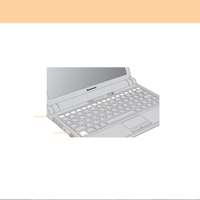
Function key combinations
Through the use of the function keys, you can change operational features
instantly. To use this function, press and hold the Fn key ; then press one
of the function keys .
b
a
12

Chapter 2. Using your computer
The following describes the features of each function key.
Fn + Esc: Disable/enable the integrated camera.
Fn + F1: Put your computer in standby mode.
Fn + F2: Turn off/on the LCD screen.
Fn + F3: Shift to other connected display devices.
Fn + F5: Open the interface for integrated wireless devices settings (enable/
disable).
Fn + F6: Enable/disable the touchpad.
Fn + F7/NmLk: Enable/disable the Numeric keypad.
Fn + F8/ScrLk: Enable/disable Scroll Lock.
Fn + F9/Break: Activate the Break function.
Fn + F10/Pause: Activate the Pause function.
Fn + F11/F12: Activate the F12 function.
Fn + PgUp/Home: Activate the Home function.
Fn + PgDn/End: Activate the End function.
Fn + Ins/SysRq: Activate the System Request.
Fn + Del/PrtSc: Activate the Print Screen function.
Fn + /: Increase/decrease display brightness.
Fn + /: Decrease/increase computer volume.
13

Chapter 2. Using your computer
OneKey™ Rescue System button (for Windows XP users only)
Press the OneKey Rescue System button to enter the main interface of
OneKey Rescue System while the power is off.
Attention:
When you press OneKey Rescue System button to turn on the computer,
please ensure that your computer is not connected with other peripherals
(such as a USB storage device, etc.), otherwise the system may not operate
properly.
For details, see OneKey Rescue System User Guide.
14
Chapter 2. Using your computer
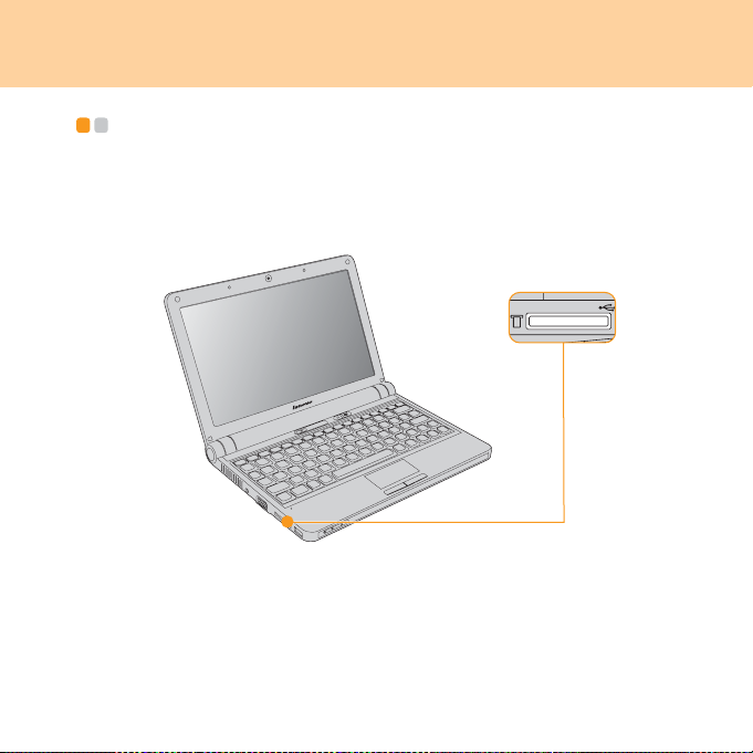
Using memory cards (purchased separately) - - - - - - - - - - - - -
Your computer comes with one memory card slot used to insert a memory
card, such as an SD Card, a MultiMediaCard, a Memory Stick or a Memory
Stick Pro.
Note:
Only use the memory card listed above; for more information about the
usage, read the instructions shipped with the memory card.
15

Chapter 2. Using your computer
Inserting a memory card
Gently slide the memory card with the arrow facing upward and pointing
toward the memory card slot. Slide until it clicks into place.
Removing a memory card
Gently pull the memory card out of the slot.
Note:
Before removing the memory card, stop it from working by Windows
Safely Remove Hardware utility, otherwise it may corrupt your data.
Using the integrated camera - - - - - - - - - - - - - - - - - - - - - - - - - - - - - - - - - - - - - - - - - - - - - - - - -
With the built-in camera, you can take photos or movies and use with various
applications, such as Windows Live Messenger or Yahoo! Messenger, and so
on.
16
Chapter 2. Using your computer
Using the Internet - - - - - - - - - - - - - - - - - - - - - - - - - - - - - - - - - - - - - - - - - - - - - - - - - - - - - - - - - - - - - - - - - - - -
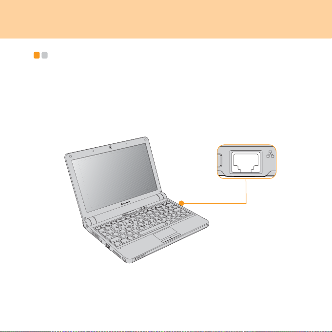
Using LAN port
The LAN port supports a standard RJ-45 connector, and allows you to
connect the computer to a high-speed DSL/cable modem connection and
local area network (LAN).
17

Chapter 2. Using your computer
Attention:
As the voltage of a telephone connection is higher than that of a network,
do not attempt to connect a telephone cable to the LAN port or else a short
circuit of the computer might occur.
Using wireless LAN
To enable wireless communications, do the following.
Press the integrated wireless device button , and confirm the system
status indicator is turned on.
18

Chapter 2. Using your computer
Using Mobile Broadband (specific models only)
Note:
Before using the Mobile Broadband, be sure to see “Safety information
related to Mobile Broadband” in Chapter 6 first.
What is Mobile Broadband
A Mobile Broadband network, also known as a Wireless Wide Area
Network (WWAN), provides Internet access to laptop computers, cell
phones and other devices over a large geographic area. Mobile networks
are used for data transmission, and access is usually provided by a mobile
network operator.
The biggest advantage of Mobile Broadband is that it is accessible from
anywhere you can get a signal from your carrier. Laptop computers with
Mobile Broadband access can stay online on the move, and will not be tied
down by a wired Internet connection.
Various standards are in use by mobile operators to provide Mobile
Broadband service. Depending on the model, your Mobile Broadband
module may support one or more of the following standards:
GSM (Global System for Mobile Communications)
TD-SCDMA (Time Division-Synchronous Code Division Multiple Access)
SCDMA (Synchronous Code Division Multiple Access)
EV-DO (Evolution Data Optimized)
HSPA (High Speed Packet Access)
19

Chapter 2. Using your computer
Note:
A mobile network operator, also known as mobile carrier, is a company
that provides mobile telecommunication service to its subscribers.
Mobile Broadband is a subscription service. Refer to your local mobile
network operator for availability, cost and other information.
Getting started with Mobile Broadband
Before getting started with Mobile Broadband, you first need to choose a
mobile network operator and make sure you are in the coverage area of the
network. After that, you also need:
To activate Mobile Broadband service through your local mobile
network operator. You will get a Subscriber Identity Module (SIM) card
after activation. For instructions on inserting the SIM card, refer to the
“Inserting the SIM card” on page 21.
Note:
A SIM card is a type of smart card used by mobile network operators to
identify their service subscribers on the mobile network. You will get the
SIM card from your mobile network operator after you have activated the
Mobile Broadband service.
A connection management utility to connect/disconnect to your Mobile
Broadband network.
Note:
In general, your mobile service provider will provide this utility.
20
Chapter 2. Using your computer
Inserting the SIM card
To in s e rt th e SIM ca r d :
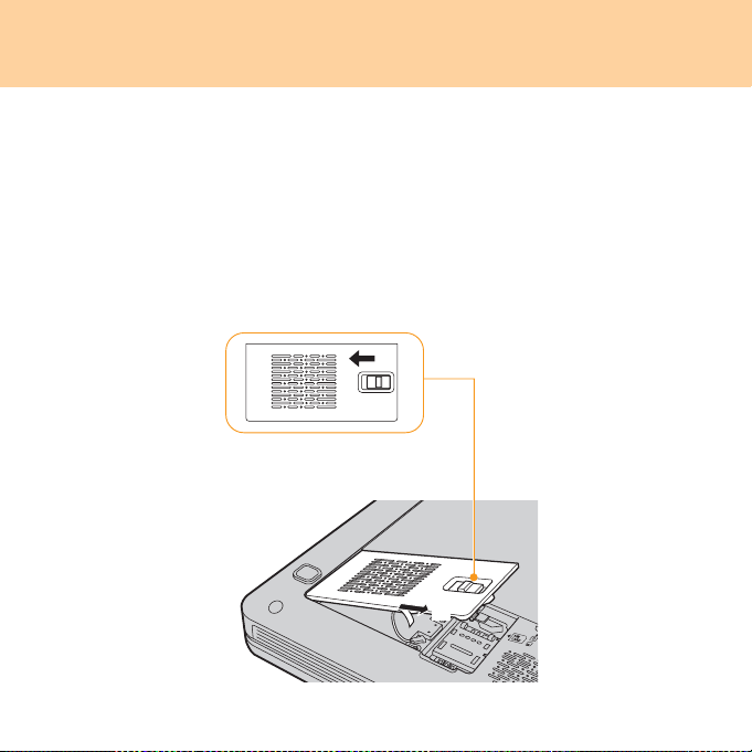
1 Turn off the computer; then disconnect the AC adapter and all cables
from the computer.
2 Close the computer display and turn it over.
3 Remove the battery.
4 Unlock the expansion slot cover latch , and then remove the
expansion slot cover .
a
b
21
Chapter 2. Using your computer
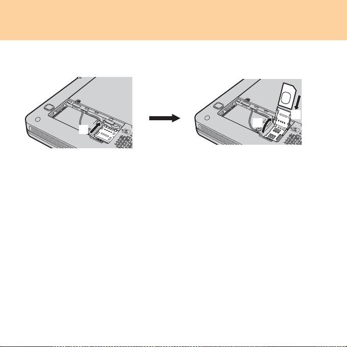
5 Unlock the card holder , lift it up and then insert the SIM card
firmly into the card holder as shown in the illustration .
a
b
6 Pivot the card holder downward, and then lock the holder.
7 Attach the expansion slot cover and lock the latch.
8 Put the battery back in place, turn the computer over again, and
reconnect the cables.
Important:
Never insert or remove the SIM card while the computer is on. Doing so may
cause permanent damage to the SIM card as well as the SIM card reader.
Be sure to lock the card holder when the SIM card is inserted.
22
c
 Loading...