

Lenovo S660 Service Manual

Company confidential
Lenovo S660 Service Manual
Publisher:NJD HW Team
Date:2014.02.28

Function Block
Company confidential
2

M/B Top Placement #1
Audio
Jack
Receiver
26M
crystal
SKY77593
MCP
Company confidential
MT6582
MT6627
MB to SB
connector
MT6166
FLASH
LED
IC
Charge
IC
Backlig
ht IC
3
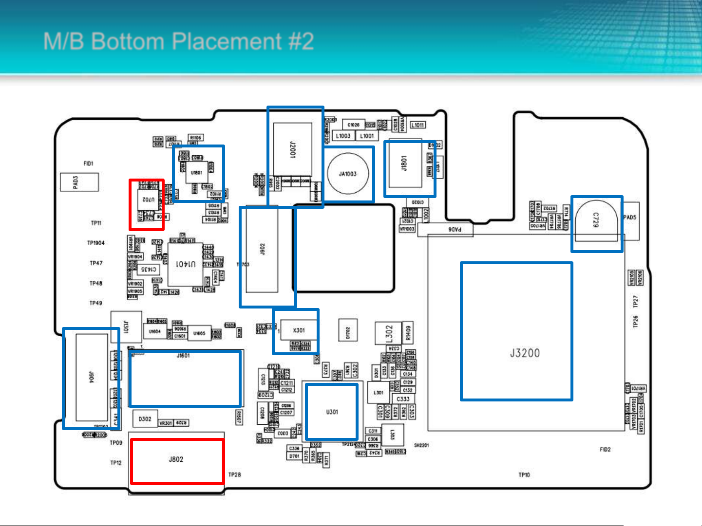
M/B Bottom Placement #2
LCM
connector
G-Sensor
Audi
o PA
TF CARD CONNECTOR
Connector
Camera
Connector
TP
32K
crystal
MT6323
Mic 2
P/L
Sensor
Connector
BACK UP
BATTERY
DUAL SIM CONNECTOR
Company confidential
Battery connector
4
BB Common Question
• BB-1 Power on failure (無法開機)
• BB-2 Firmware update failure (無法更新軟件)
• BB-3 Charging failure (無法充電)
• BB-4 SIM Card identified error (SIM卡無法識別)
• BB-5 LCD display error (畫面無法顯示或顯示異常)
• BB-6 Sensor function failure (感測器不良)
• BB-7 Touch Panel function failure (無法觸屏)
• BB-8 Vibrator function failure (馬達無振動)
• BB-9 Camera shooting failure (無法攝像)
• BB-10 MIC function failure (麥克風無作用)
• BB-11 Speaker function failure (喇叭無聲)
• BB-12 Audio function failure (Audio 不良)
• BB-13 SD Card function failure (SD Card無作用)
Company confidential
5

BB-1 Can not power on (無法開機) (1/3)
• 1. Check if battery power level is low (確認電池是否有電?)
– VBATT (TP09 > 3.6V)
• 2. Check if J802 soldering condition is good (確認J802吃錫狀況是否正常?)
• 3. Check if power button is functional (確認開機鍵是否正常?)
– PWRKEY(TP11 > 2.8V)
– TP11 connect with ground wire to power on (跟地短路後可將系統開機)
TP11 > 2.8V
TP09 > 3.6V
Company confidential
6

BB-1 Can not power on (無法開機) (2/3)
• 5. Please check whether MT6323 voltage is normal (請確認MT6323周圍電壓是否
正常?)
– VPROC_PMU should be between C134 (0.9V~1.1V)
– VSYS_PMU should at R373 (1.8V)
VPROC_PMU
Company confidential
VSYS_PMU
7

BB-1 Can not power on (無法開機) (3/3)
MT6323 Power On/Off sequence
VCORE≈0.7V~1.3V
VPORC≈0.7V~1.3V
VIO18=1.8V
VIO28=2.8V
VM12_INT=1.2V
VA1=2.5V
VA2=2.5V
VUSB=3.3V
VTCXO=2.8V
Company confidential
VMC=3.3V
VMCH=3.3V
RESET=1.8V
8
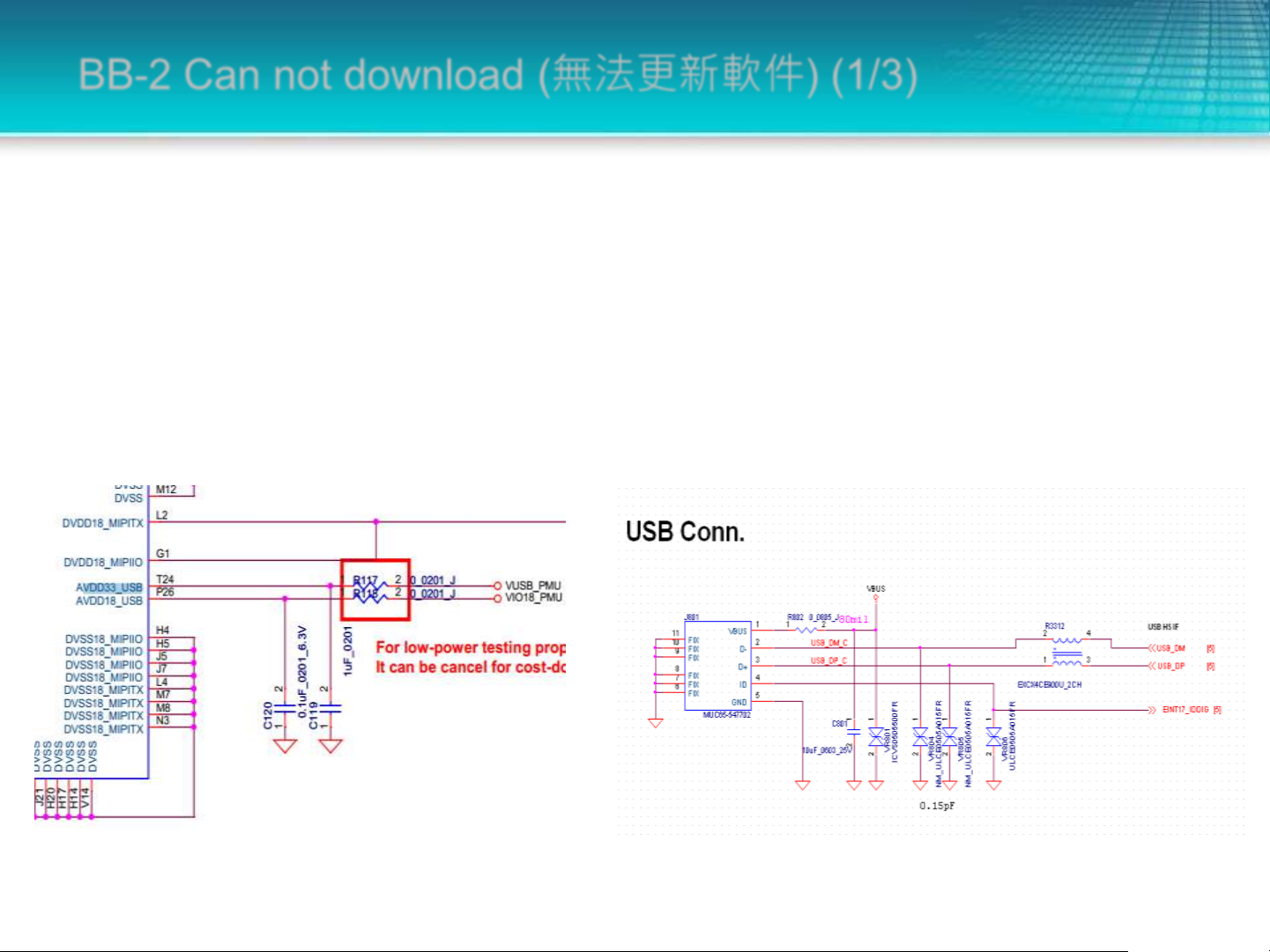
BB-2 Can not download (無法更新軟件) (1/3)
• 1. Please check whether current is normal after boot (確認開機後電流起跳正常)
• (記憶體中無代碼時,電池電流約在0.1A左右)
• 2. If current in booting process is larger or less than normal, USB port will be
unidentified (開機過程中如果電流過大或過小,會造成USB port無法識別)
• 3. Please check if R3312 is solid soldering on (檢查SB的R3312是否空焊)
Company confidential
9
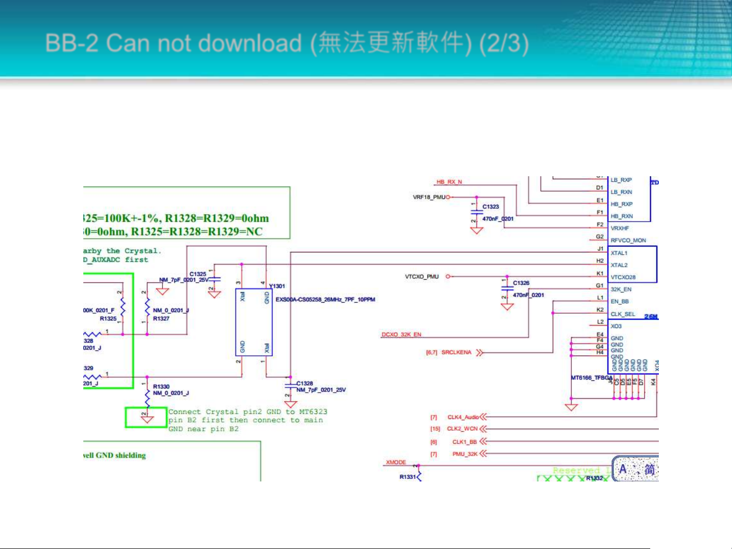
BB-2 Can not download (無法更新軟件) (2/3)
• 4. If DL is passed, and META mode is un-entered, check RF transceiver 26MHz
and RF chip function (若可以正常DL,但無法進入META mode,檢查RF
transceiver 26MHz及RF chip是否正常。)
Company confidential
10

BB-2 Can not download (無法更新軟件) (3/3)
• 5. Check if com port is correct (確認com port是否正確)
Company confidential
11

BB-3 Can not charging (無法充電) (1/2)
• 1. Check if battery resistance R332 Pin1(BAT_ID) is 10kΩ when
battery is installed (確認電池內阻R332 Pin1 (BAT_ID), 當接上電池
後阻抗應該約10kΩ.)
• 2. Check battery voltage, if 0V reveals open circuit (確認電池電壓
是否為正常,異常為0V (開路))
• 3. Check if J801 USB connector failure (確認J801 USB connector
是否有異狀?)
Company confidential
12

BB-3 Can not charging (無法充電) (2/2)
• 4. Check charging IC and related circuit soldering condition is good (確認充電IC
及周围电路焊接是否正常。)
– When USB port has be inserted, VBUS should be at 5V output (VBUS在USB
插入時,是否有5V左右的电压输出。)
Company confidential
13

BB-4 SIM Card Identification error (SIM卡無法識別) (1/2)
• 1. Check if SIM Card is in normal condition (更換SIM卡,確認卡片是否正常?)
• 2. Check if J3200 soldering condition is normal (確認J3200吃錫狀況是否正常?)
• 3. Check SIM related signal SRST, VSIM, SIO and SCLK (確認SIM 相關訊號)
– SRST, VSIM,SIO and SCLK
Company confidential
14

BB-4 SIM Card Identification error (SIM卡無法識別) (2/2)
SIM1/SIM2的供电电
压各来自PMU的两
组LDO output
SIM1/SIM2 output
voltage are coming
from two LDO
output of PMU
SIM1和SIM2的
DATA/RST/CLOCK
单独分开使用
DATA/RST/CLOCK
of SIM1 and SIM2
are used
seperately
Company confidential
15

BB-5 Can not display (畫面無法顯示或顯示異常)
• 1. Check J904 soldering condition (確認J904是否有異狀[鍚短 or 空焊]?)
• 2. Replace LCD (更換LCM)
• If failure still exists after LCM replacement (若更換良品後,現象還存在)
• 3. Check L1202 L1203 L1204 condition (檢查L1202, L1203, L1204否有異狀?)
• 4. Check if LCM voltage (VIO28_PMU及VIO18_PMU) are correct (確認LCM 電壓
(VIO28_PMU及VIO18_PMU)位準是否正確?)
• 5. Check U901, L901, D901, R903 if back light is in failure (若無背光,確認U901,
L901, D901, R903)
LCM兩組工作電壓
Company confidential
16

BB-6 sensor function fail (感測器不良) (1/2)
• 所有的sensor都是由I2C總線,中斷信號,電源組成.I2C總線上sensor間會相互影響,
所以維修某個 sensor不良時需要同步檢查其他sensor路徑。
• All sensors are consisted by I2C bus, interrupt signal and power. Sensors on
I2C bus are affected by each other, therefore related sensors checking is
needed when repairing sensor.
G-sensor供电电压。该电压等同于
VIO18,该电压异常系统就无法开起来,
所以sensor不良不用check此电位。
G-Sensor voltage is as same as
VIO18. if this voltage is in error,
system will not boot on. Therefore
it is not necessary to check this
voltage when sensors are on failure
Company confidential
17

BB-6 sensor function fail (感測器不良) (2/2)
G-sensor I2C通過上拉電阻連接到CPU,此I2C與touch panel共用,
VDD18_PMU異常會造成所有sensor fail。
G-sensor I2C connect to CPU with Pull-up resistor, which share
with touch panel, VDD18_PMU error will lead to all sensors
failure.
Company confidential
18
 Loading...