

Lenovo S650 Service Manual
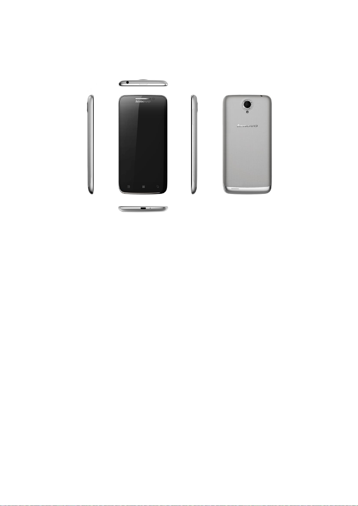
1 Cellphone appearance
2 Layout of motherboard
Front of motherboard:
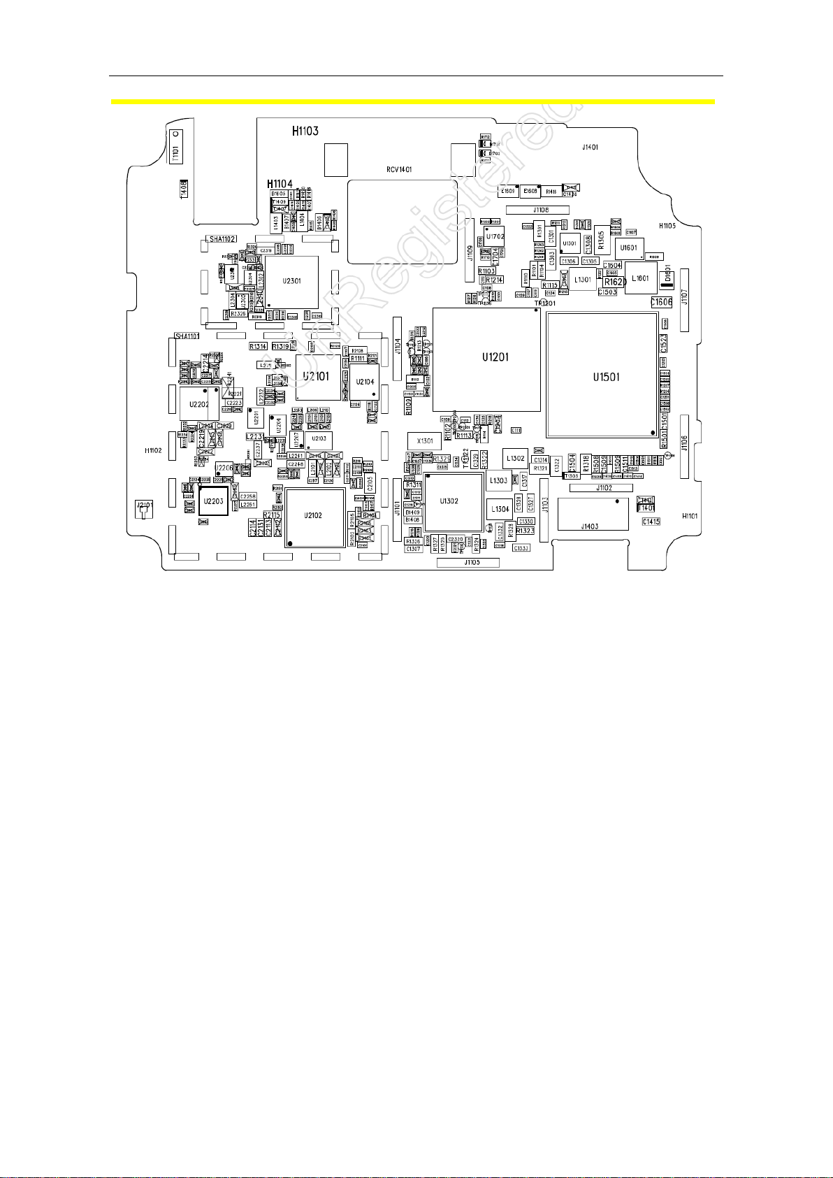
LENOVO S650 Cellphone Service Manual
Back of motherboard:
Page 2
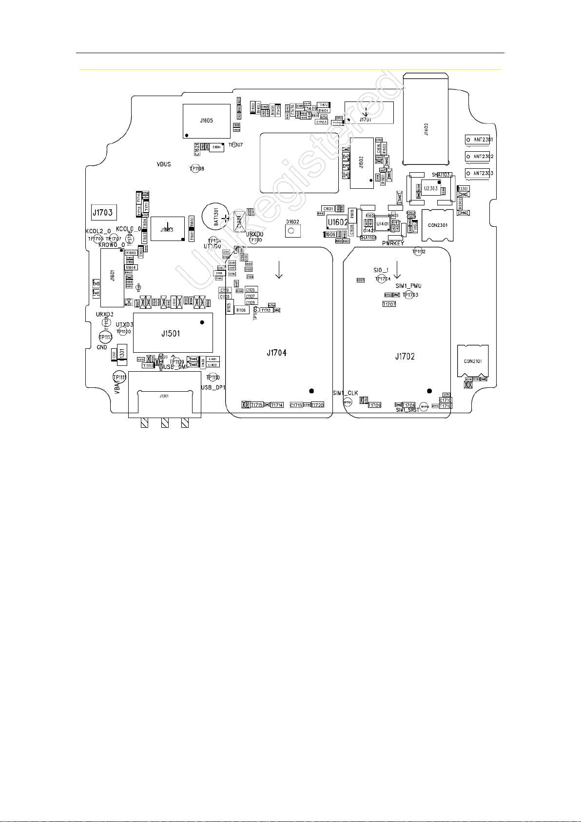
LENOVO S650 Cellphone Service Manual
Page 3
LENOVO S650 Cellphone Service Manual
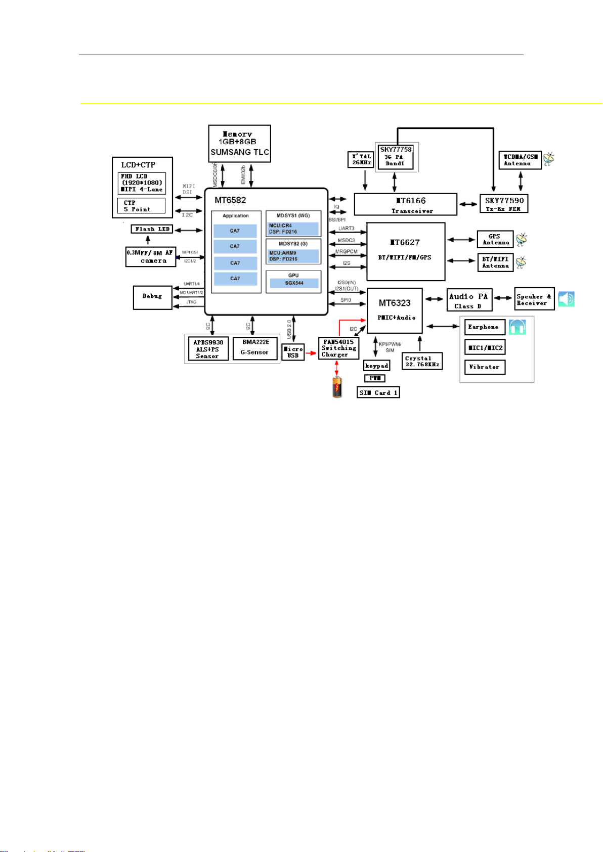
3 Baseband
Electronic circuit diagram
3.1 LCD display
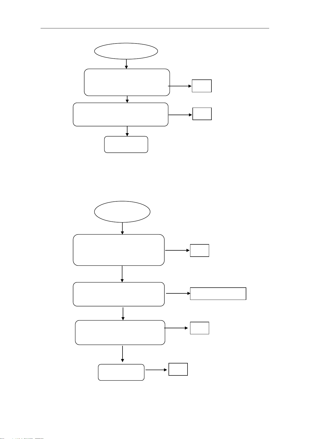
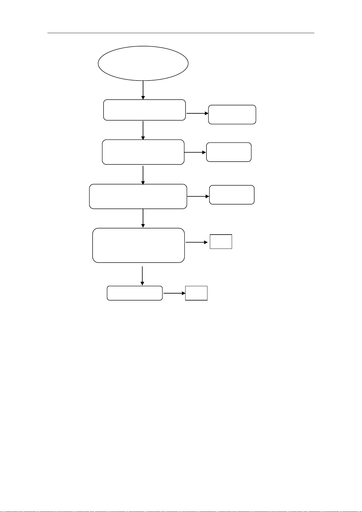
3.1.1 When the device is turned on there’s
nothing on screen
Page 4
LENOVO S650 Cellphone Service Manual
Check whether the correct voltage is
applied on the positive and negative
backlight terminals of the LCD module.
OK
OK
Replace the LCD
module.
Y
Y
Y
Y
OK
Check whether connections between FPC
of LCD module and connectors on
motherboard are good. Reconnect them.
Check whether LCD backlight works.
N
LCD backlight
doesn’t light up.
Check whether the output of the backlight
circuit at the motherboard end is correct.
Check whether chip U1601 works.
Replace U1601.
N
N
Screen is blank.
Check whether the EMI components in LCD
channel on motherboard have dry joint
problems. Re-solder the EMI components.
OK
Replace the LCD
module.
Check whether the connectors of the
LCD are attached correctly. Re-install
FPC. Check whether the cellphone
works.
N
N
Y
OK
Y
3.1.2 LCD backlight doesn’t light up.
Page 5
LENOVO S650 Cellphone Service Manual
Can’t take
photos.
OK
Check whether the EMI components
are integrated and check their solder
joints. Repair the EMI components.
Check the solder joints of U1201.
Re-solder or replace
U1201.
N
Y
N
Repair soldering, and
try again.
N
N
Replace the Camera
module. Check whether it
can take photos.
Check the solder joints of the Camera
module connectors. Repair soldering on
the connectors. Check whether it can
take photos.
N
Y
OK
Dissemble the unit. Check whether the
Camera module is detached. Re-assemble the
module. Check whether it can take photos.
N
Y
OK
3.2 Cameras do not work properly.
3.2.1 Back camera does not work
properly.
Page 6
LENOVO S650 Cellphone Service Manual
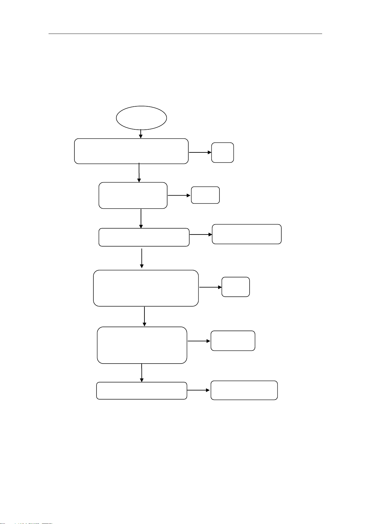
Can’t take
photos.
OK
Check whether the EMI
components are integrated and
check their solder joints. Repair
the EMI components.
Check the solder joints of U1201.
Re-solder or replace
U1201.
N
Y
N
Repair
soldering, and
N
N
Replace the Camera
module. Check whether
it can take photos.
Check the solder joints of the Camera
module connectors. Repair soldering on
the connectors. Check whether it can
take photos.
N
Y
OK
Dissemble the unit. Check whether the
Camera module is detached. Re-assemble the
module. Check whether it can take photos.
N
Y
OK
Check whether the module’s
connectors are deformed.
Replace connector J1605.
Y
N
3.2.2 Front camera doesn’t work
properly.
Page 7
LENOVO S650 Cellphone Service Manual
Check whether the solder joints of the motor
and the peripheral components are normal.
Re-solder and retry to see whether the
problem is fixed.
OK
Y
It does not
vibrate.
N
Use a multi-meter to check whether the
terminal voltage difference between the
two leads of the motor in the Motor
Vibration mode is higher than 2.6V.
Replace the
motor.
N
Y
OK
Y
Replace chip U1302
N
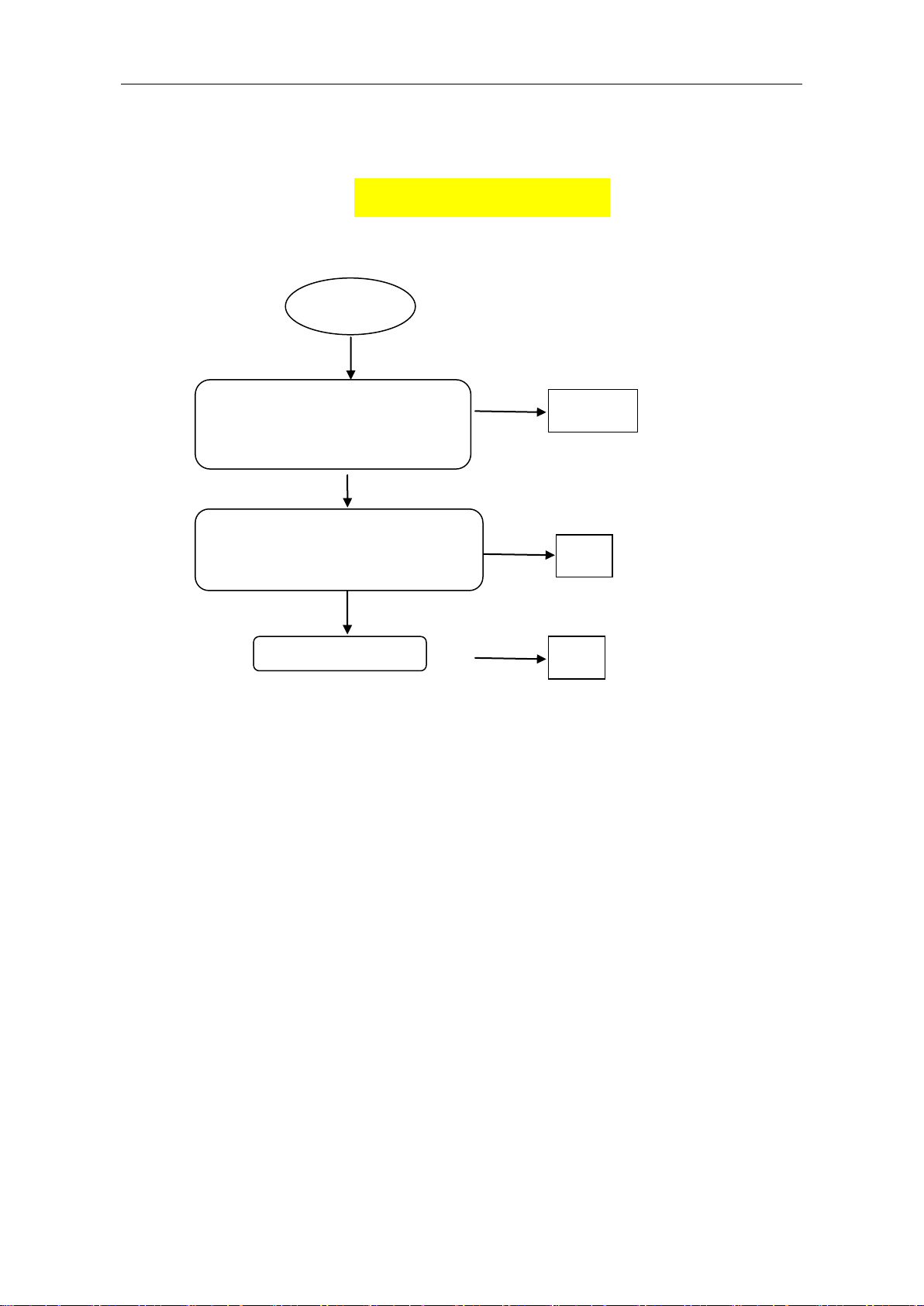
3.3 Ring and Vibration
3.3.1 It does not vibrate.
3.3.2 It does not ring.
3.3.2.1 SI-EN audio power amplifier
Page 8

LENOVO S650 Cellphone Service Manual
Check PMU chip U1302. If it’s damaged,
replace it.
Check whether audio power amplifier U3001
on subboard has a dry joint problem or is
damaged. Repair soldering or replace it. Try
again to see whether it rings.
N
Replace speaker. Retry to see whether it
rings.
Y
OK
Y
OK
It does not ring.
N
Check whether the connections of the
main FPC connectors are OK.
Y
OK
N
Y
OK
Check whether the contacts between the
speaker spring clips and the sound
chamber stand are good.
Replace the sound chamber stand.
Y
N
3.4 Charging
1
3.4.1 It doesn’t show the charging
indicator when charger is plugged
in.
Page 9
LENOVO S650 Cellphone Service Manual
Replace the charger. Check
whether it can charge normally.
Replace the
charger.
It doesn’t show the
charging indicator when
charger is plugged in.
Y
Replace the battery. Check whether it
can charge normally and the battery’s
voltage is lower than 3V.
Replace the
battery.
Y
N
Check the solder joints of the
components of the charging chip module U1301. Re-solder. Check
whether the problem is fixed.
Y
OK
N
Replace U1201.
Y
OK
N
Re-fasten battery connector
J1301. Check whether it can
charge normally.
OK
Y
N
Page 10
 Loading...