

Lenovo LXM-L19BH Service Manual
Lenovo LXM-L19BH
L
SERVICE MANUA
LXM-L19BH
http://www.wjel.net
THESE DOCUMENTS ARE FOR REPAIR SERVICE INFORMATION ONLY.EVERY REASONABLE
EFFORT HAS BEEN MADE TO ENSURE THE ACCURACY OF THIS MANUAL; WE CANNOT
GUARANTEE THE ACCURACY OFTHIS INFORMATION AFTER THE DATE OF PUBLICATION AND
DISCLAIMS RELIABILITY FOR CHANGES, ERRORS OR OMISSIONS.
MANUFACTURE DATA :May-24-2005
Page 1 of 44

Lenovo LXM-L19BH
TABLE OF CONTENTS
1. MONITOR SPECIFICATIONS ..................................................................................................................................... 5
2. LCD MONITOR DESCRIPTION .................................................................................................................................. 6
3. OPERATING INSTRUCTIONS .................................................................................................................................... 7
3.1 GENERAL INSTRUCTIONS................................................................................................................................... 7
3.2 CONTROL BUTTON............................................................................................................................................... 7
3.2 ADJUSTING THE PICTURE................................................................................................................................... 8
4. INPUT/OUTPUT SPECFICATION ............................................................................................................................... 9
4.1 15 - PIN D-SUB SIGNAL ......................................................................................................................................... 9
4.2 FACTORY PRESET DISPLAY MODES: ............................................................................................................ 10
4.3 POWER SUPPLY (ROOM TEMPERATURE 25℃±4℃) ....................................................................................... 10
4.4 PANE L SPECIFICATION .......................................................................................................................................11
5. BLOCK DIAGRAM ..................................................................................................................................................... 13
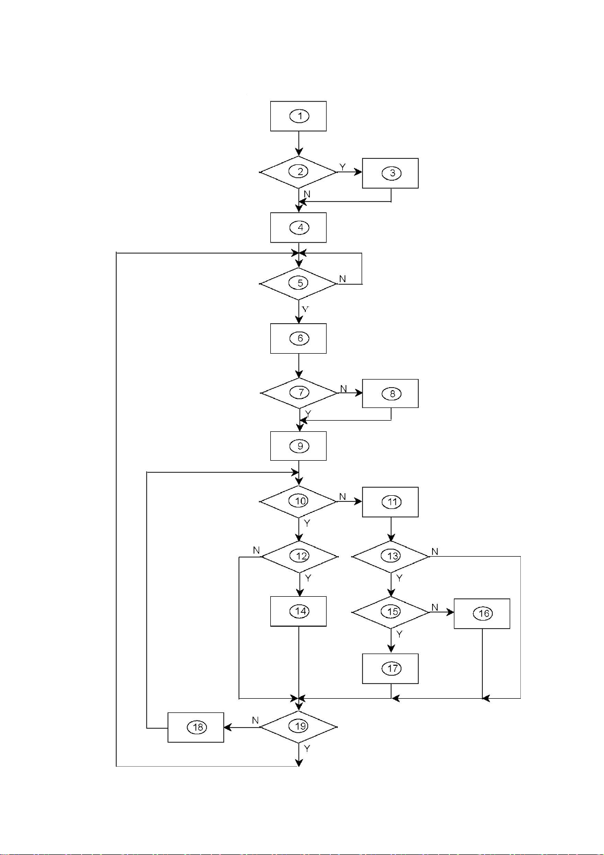
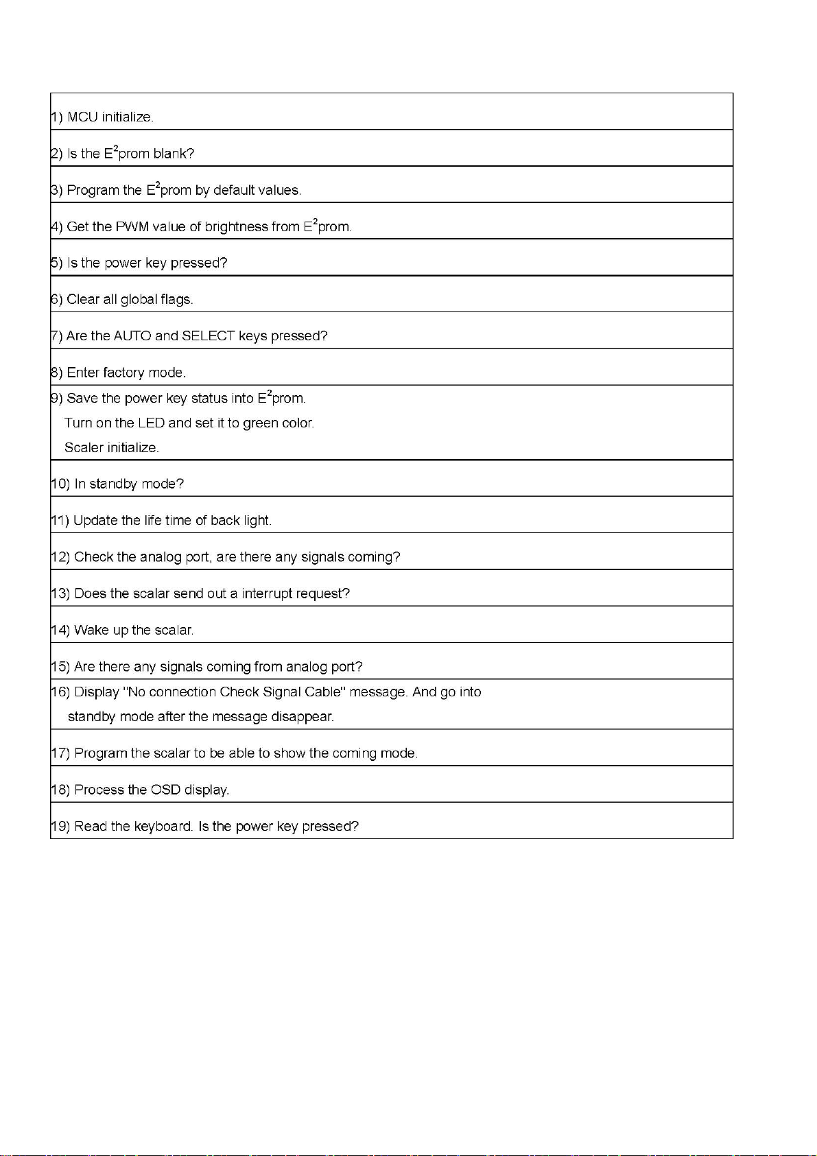
5.1 SOFTWARE FLOW CHART ................................................................................................................................. 13
5.2 ELECTRICAL BLOCK DIAGRAM.........................................................................................................................15
5.2.1 SCALAR BOARD BLOCK DIAGRAM............................................................................................................ 15
5.2.2 INVERTER/POWER BOARD BLOCK DIAGRAM ......................................................................................... 17
6.SCHEMATIC ............................................................................................................................................................... 19
6.1 MAIN BOARD ....................................................................................................................................................... 19
6.2 INVERTER BOARD .............................................................................................................................................. 26
7. PCB LAYOUT............................................................................................................................................................. 27
7.1 MAIN BOARD ....................................................................................................................................................... 27
7.2 POWER/INVERTER BOARD ............................................................................................................................... 28
8. MAINTAINABILITY ..................................................................................................................................................... 29
8.1 EQUIPMENT AND TOOLS REQUIREMENT........................................................................................................ 29
8.2 TROUBLE SHOOTING......................................................................................................................................... 30
9 WHITE-BALANCE, LUMINANCE ADJUSTMENT ...................................................................................................... 35
http://www.wjel.net
10. EDID CONTENT ...................................................................................................................................................... 36
11.BOM LIST.................................................................................................................................................................. 37
Page 2 of 44

Lenovo LXM-L19BH
Revision List
Revision Date Change Description
http://www.wjel.net
Page 3 of 44
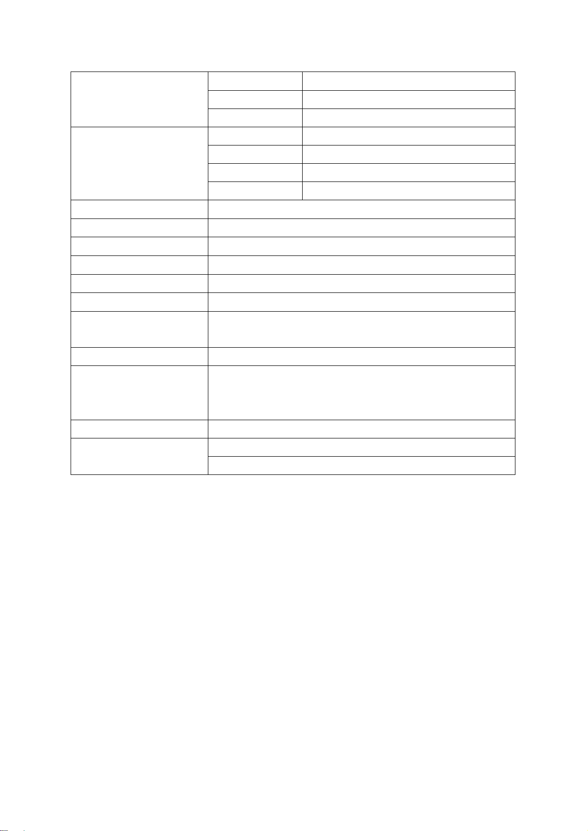
1. MONITOR SPECIFICATIONS
Type Color TFT LCD
Lenovo LXM-L19BH
LCD Panel
Input
Display Color 16.7M Colors
Dot Frequency 135MHz
Max. Frequency 1280 x 1024
Drug and Play VESA DDC2BTM
Input Interface D-Sub 15Pin
Input Signal Analog 0.7Vpp Positive Signal / 75 Ohm
Max. Display Area
Power DC 12VDC, 3.5A
Environmental Temperature
Humidity
Size 48cm(19inch)
Pixel Pitch 0.294mm(H) x 0.294mm(V)
Video R. G. B analog interface
Separate Sync H/V TTL
H Frequency 30kHz - 80kHz
V Frequency 50Hz-75Hz
Horizontal: 376.32mm
Vertical: 301.06mm
Operating Temperature: 0°C to 40°C (32°F to 104°F)
Storing Temperature: -20°C to 60°C ( -4°F to 140°F)
Operating Humidity: 10% to 85%
Weight (net) 4.4kg
ON Mode: ≤42 Watts
Max. Power Consumption
OFF Mode:
http://www.wjel.net
≤3 Watts
Page 4 of 44

Lenovo LXM-L19BH
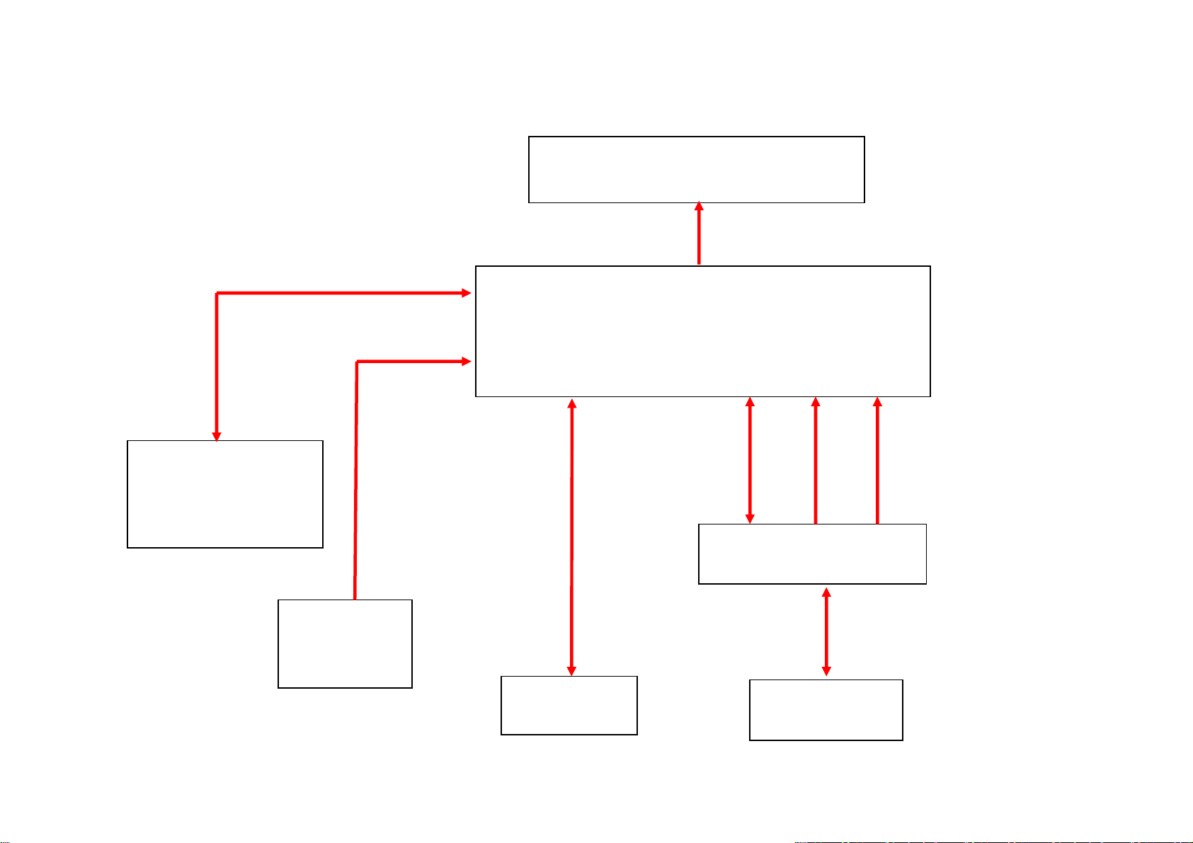
2. LCD MONITOR DESCRIPTION
The LCD MONITOR will contain a main board, an inverter/Power board and a keypad board which house the flat panel
control logic, brightness control logic and DDC.
The Inverter board will drive the backlight of panel and the DC-DC conversion.
Inverter/Power board
Monitor Block Diagram
CCFL Drive.
Keyboard
Flat Panel and
CCFL backlight
Main Board
RS232 Connector
For white balance
adjustment in factory
mode
DC-IN
100V-240V
HOST Computer
Video signal, DDC
http://www.wjel.net
Page 5 of 44
Lenovo LXM-L19BH
3. OPERATING INSTRUCTIONS
3.1 GENERAL INSTRUCTIONS
Press the power button to turn the monitor on or off. The other control buttons are located by the side of the monitor. By
changing these settings, the picture can be adjusted to your personal preferences.
The power cord should be connected.
-
Connect the video cable from the monitor to the video card.
-
Press the power button to turn on the monitor, the power indicator will light up.
-
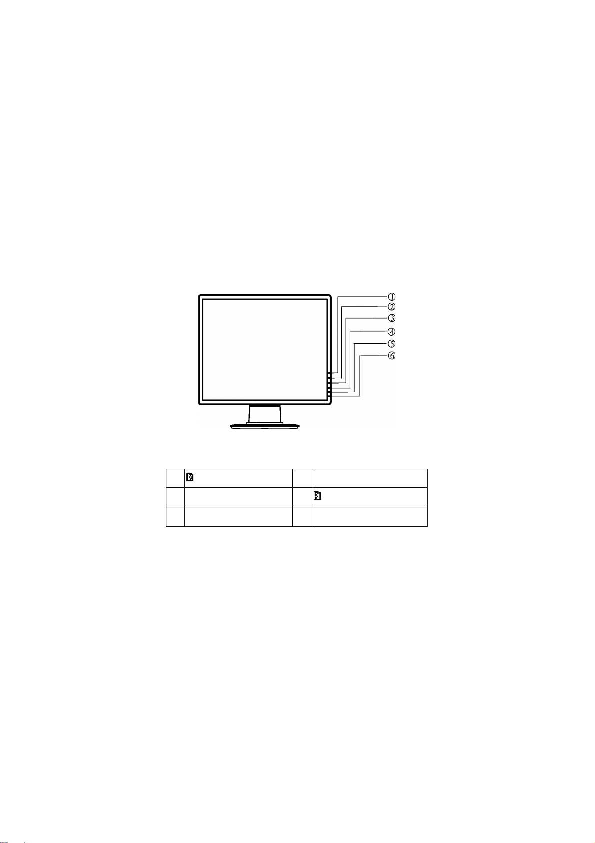
3.2 CONTROL BUTTON
Power Indicator condition:
Green — Power On mode
Orange — Power Saving mode
1.
/ Auto Adjust / Exit
3. ▼/ Contrast Adjust 4.
5. Power Indicator 6. Power Switch
2. ▲/ Brightness Adjust
/ Menu/ Select
http://www.wjel.net
Page 6 of 44
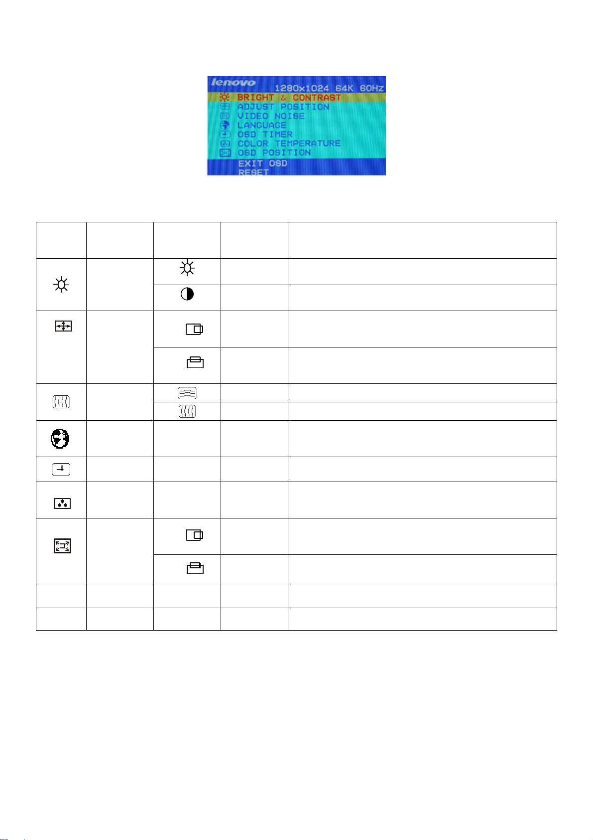
3.2 ADJUSTING THE PICTURE
The description for control function:
Lenovo LXM-L19BH
Menu
Icon
Adjust
Color
Menu Item Sub Menu
Brightness &
Contrast
Position
Video Noise
Language
OSD Timer
Temperature
Sub Menu
Icon
Horizontal
Vertical
Item
Brightness Adjust the brightness.
Contrast Adjust the contrast.
Position
Position
Phase Adjust the Phase.
Clock Adjust the Clock.
Set OSD Language.
Set the display time of OSD menu.
Color Temperature choose(7800K、6500K、user mode)
Function Description
Adjust the horizontal position.
Adjust the vertical position.
OSD Position
Exit OSD
Reset
OSD
http://www.wjel.net
Horizontal
Adjust the Horizontal Position of OSD menu.
OSD Vertical Adjust the Vertical Position of OSD menu.
Exit OSD
Reset the factory preset configuration
Page 7 of 44
4. INPUT/OUTPUT SPECFICATION
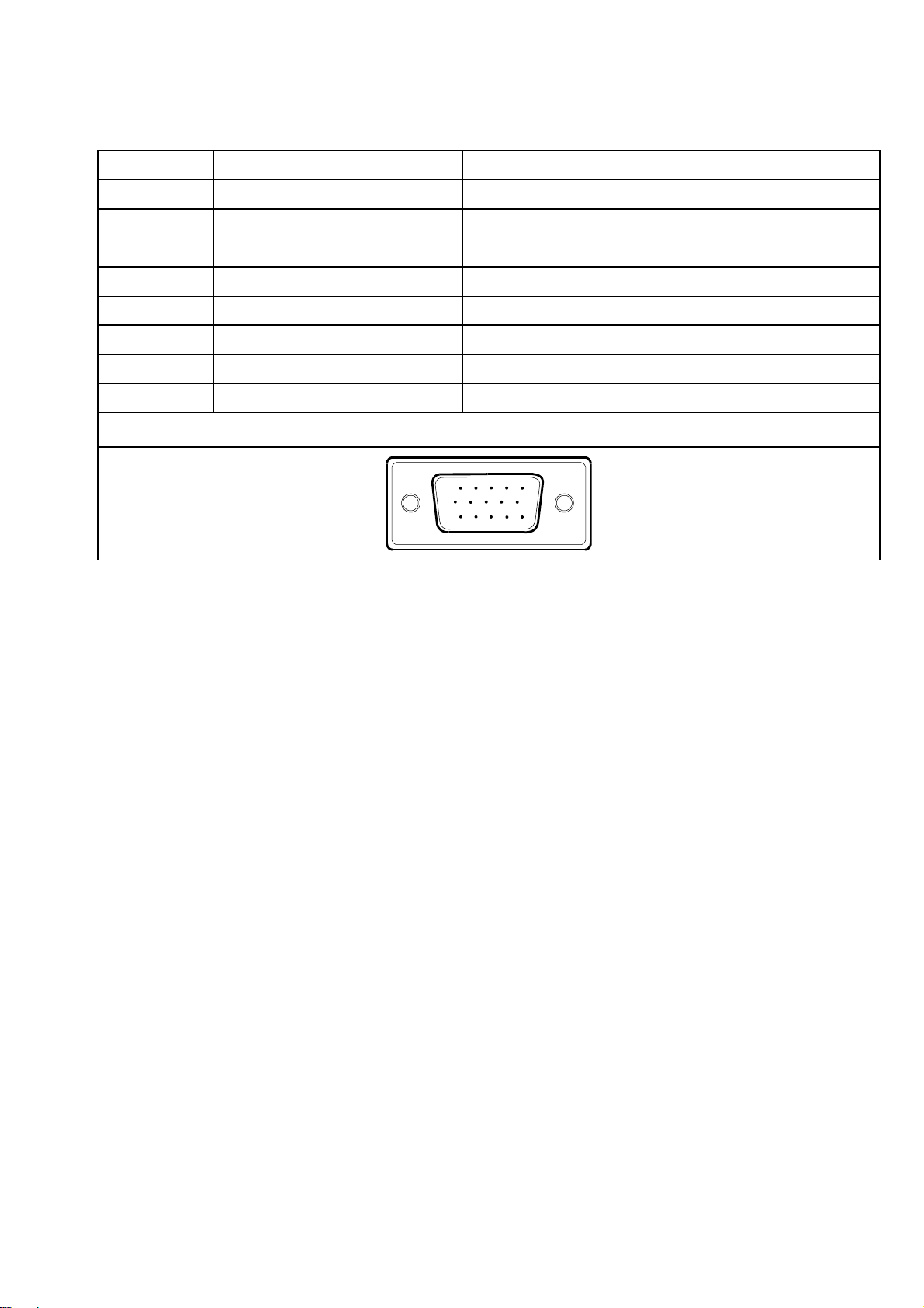
4.1 15 - Pin D-Sub Signal
PIN NO. DESCRIPTION PI N NO. DESCRIPTION
1. Red 9. +5V
2. Green 10. Logic GND
3. Blue 11. GND
4. Ground 12. DDC-Serial Data
5. Ground 13. H-Sync
6. R-Ground 14. V-Sync
7. G-Ground 15. DDC-Serial Clock
8. B-Ground
VGA Connector layout
15
6
11 15
10
Lenovo LXM-L19BH
http://www.wjel.net
Page 8 of 44
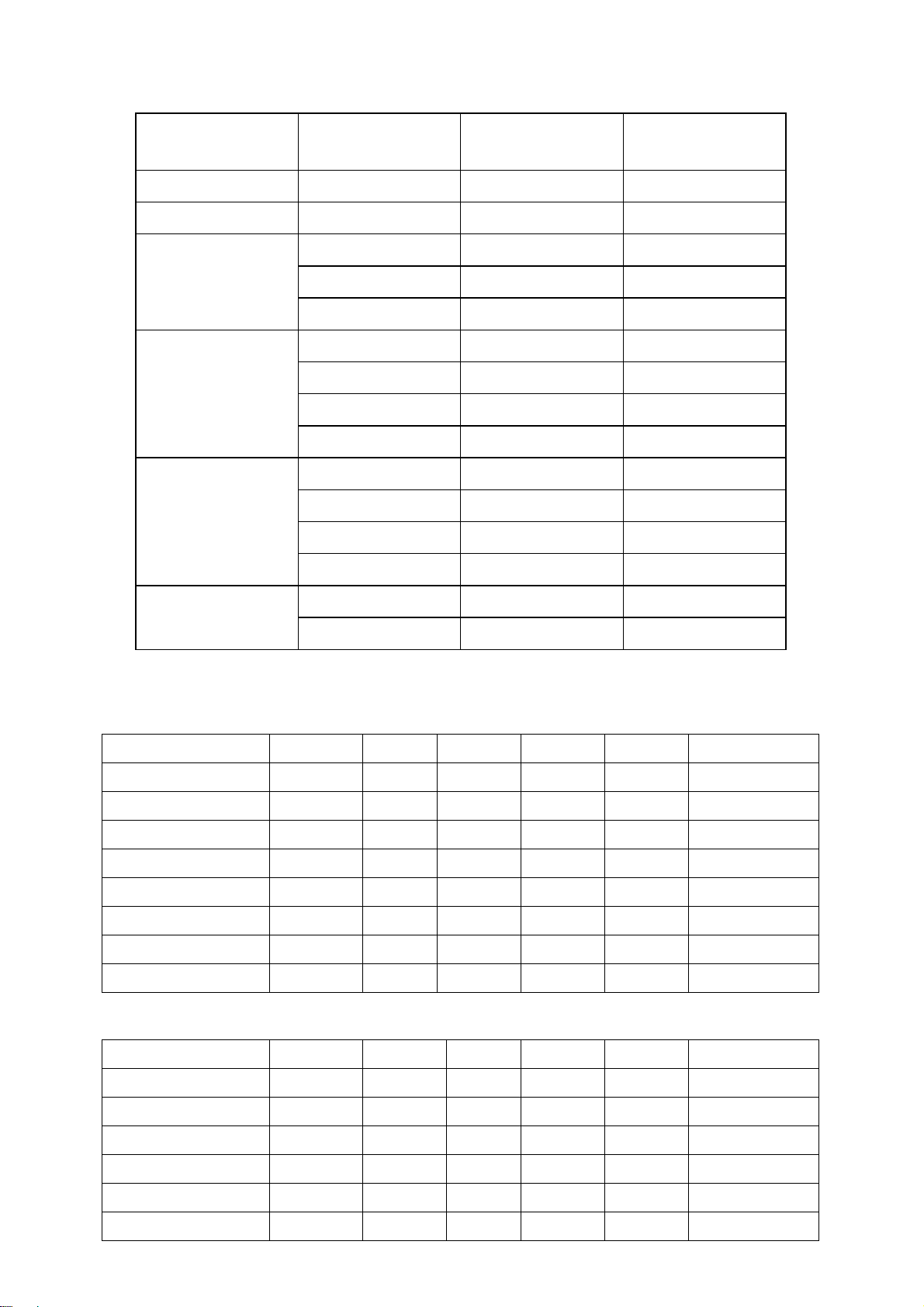
4.2 FACTORY PRESET DISPLAY MODES:
Lenovo LXM-L19BH
Standard
Dos-Mode
Dos-Mode
VGA
SVGA
XGA
Resolution
640 × 400 31.47kHz 70Hz
720 × 400 31.47kHz 70Hz
640 × 480 31.47kHz 60Hz
640 × 480 37.861kHz 72Hz
640 × 480 37.50kHz 75Hz
800 × 600 35.156kHz 56Hz
800 × 600 37.879kHz 60Hz
800 × 600 48.077kHz 72Hz
800 × 600 46.875kHz 75Hz
1024 × 768 48.363kHz 60Hz
1024 × 768 56.476 kHz 70 Hz
1024 × 768 56.476kHz 70Hz
1024 × 768 60.02kHz 75Hz
Horizontal
Vertical Frequency
Frequency
SXGA
1280 × 1024 64.000kHz 60Hz
1280 × 1024 80.000kHz 75Hz
4.3 Power Supply (ROOM TEMPERATURE 25℃±4℃)
4.3.1 INVERTER MAX BRINGTHNESS (Vadj:5.0V), LOAD=120KΩX4
ITEM SYMBOL MIN. TYP. MAX. UNIT REMARK
Input voltage
Input current Iin 2200 2450 mA FOR 4 LOAD
Output Current Iout 6.0 6.5 7.0 mA FOR 1 LOAD
Frequency F 52.0 57.0 62.0 KHZ FOR 1 LOAD
H.V open
H.V Load
Start voltage Vst 1700 1850 2000 Vrms RL=CCFL
Protect delay time PDT 0.1 1 4 Sec
4.3.2 INVERTER MIN BRINGTHNESS (Vadj: 0.0V), LOAD=120KΩX4
http://www.wjel.net
Vin
Vopen
Vload
10.8 12 13.2 V
1500 1650 1800 Vrms NO LOAD
710 810 910 Vrms
RL=120KΩ
ITEM SYMBOL MIN. TYP. MAX. UNIT REMARK
input voltage Vin 10.8 12 13.2 V
input current Iin 740 820 mA FOR 4 LOAD
Output Current Iout 3.0 3.5 4.0 mA FOR 1 LOAD
Frequency F 52.0 57.0 62.0 KHZ FOR 1 LOAD
H.V open Vopen 1500 1650 1800 Vrms NO LOAD
Start voltage Vst 1700 1850 2000 Vrms RL=CCFL
Page 9 of 44
Lenovo LXM-L19BH
H.V Load Vload 350 450 550 Vrms RL=120KΩ
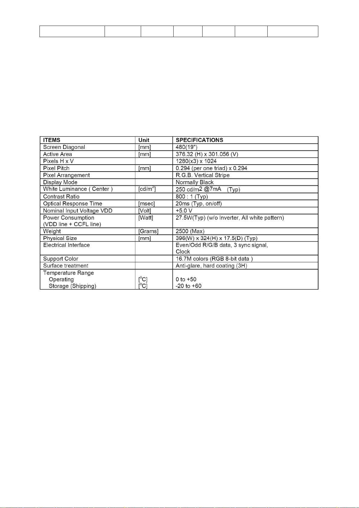
4.4 PANEL SPECIFICATION
4.4.1 PANEL FEATURE
This specification applies to the 19.0 inch Color TFT-LCD Module M190EN03 V1. The display supports the SXGA
(1280(H) x 1024(V)) screen format and 16.7M colors (RGB 8-bits data). All input signals are 2 Channel LVDS interface
compatible. This module does not contain an inverter card for backlight.
4.4.2 DISPLAYS CHARACTERISTICS
The following items are characteristics summary on the table under 25 ℃ condition:
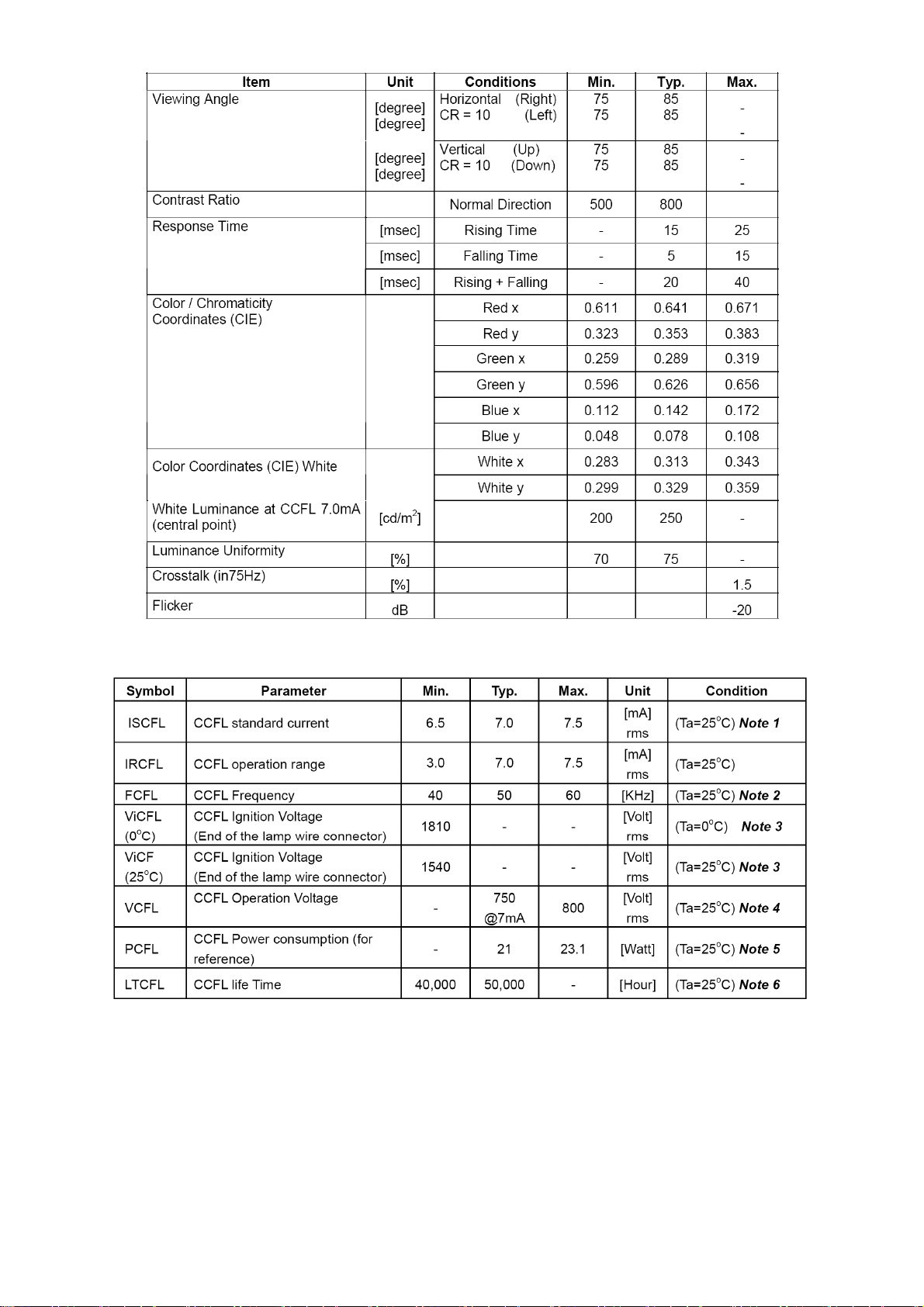
4.4.3 OPTICAL CHARACTERISTICS
The optical characteristics are measured under stable conditions at 25℃:
http://www.wjel.net
Page 10 of 44
Lenovo LXM-L19BH
4.4.4 Parameter guideline for CCFL Inverter
http://www.wjel.net
Note 1: CCFL standard current is measured at 25±2℃..
Note 2: CCFL Frequency should be carefully determined to avoid interference between inverter and TFT LCD
Note 3: ViCFL means Ignition Voltage for both ends of the lamp, and CCFL inverter should be able to give out a power
that has a generating capacity of over 1810 voltage. Lamp units need 1810 voltage minimum for ignition
Note 4: CCFL operation voltage is measured at 25±2℃.
Note 5: The variance of CCFL power consumption is ±10%. Calculator value for reference (ICFL×VCFL×4=PCFL).
Note 6: Definition of life: brightness becomes 50% or less than the minimum luminance value of CCFL. The typical life
time of CCFL is on the condition at 7.0mA lamp current.
Page 11 of 44
5. BLOCK DIAGRAM
5.1 SOFTWARE FLOW CHART
Lenovo LXM-L19BH
http://www.wjel.net
Page 12 of 44
Lenovo LXM-L19BH
http://www.wjel.net
Page 13 of 44
5.2 ELECTRICAL BLOCK DIAGRAM
5.2.1 SCALAR BOARD BLOCK DIAGRAM
Lenovo LXM-L19BH
LCD Interface (LVDS)
CN403
OSD Control
Interface
(Keypad)
CN402
Crystal
14.31818 MHz
X401
http://www.wjel.net
EEPROM
U402
(Include MCU,ADC,OSD)
EPR_SDA
EPR_SCL
Scalar
GM2321 PQFP-208
U401
RXD
TXD
D-Sub Connector
H Sync
V Sync
CN301
EEPROM
U302
RGB
DB15_SDA
DB15_SCL
Page 14 of 44
 Loading...