

Page 1

LenovoC355/C455All-In-OneComputer
ideaideaideaCentreidea
HardwareMaintenanceManual
MachineTypes:10138/F0A2[C355],10139/F0A3[C455]
Page 2

Page 3

LenovoC355/C455All-In-OneComputer
HardwareMaintenanceManual
MachineTypes:10138/F0A2[C355],10139/F0A3[C455]
Page 4

SecondEdition(July2013)31st
©CopyrightLenovo2013.
LIMITEDANDRESTRICTEDRIGHTSNOTICE:IfdataorsoftwarearedeliveredpursuantaGeneralServices
Administration“GSA ”contract,use,reproduction,ordisclosureissubjecttorestrictionssetforthinContractNo.
GS-35F-05925
Page 5

Contents
Chapter1.Aboutthismanual......1
ImportantSafetyInformation..........1
Chapter2.Safetyinformation......3
Generalsafety................3
Electricalsafety...............3
Safetyinspectionguide............5
Handlingelectrostaticdischarge-sensitive
devices..................5
Groundingrequirements............6
Safetynotices................6
Chapter3.Generalinformation.....9
Specications................9
Chapter4.GeneralCheckout.....11
Chapter5.UsingtheSetupUtility...13
StartingtheLenovoBIOSSetupUtilityprogram.13
Viewingandchangingsettings........13
Usingpasswords..............13
Enablingordisablingadevice........15
Selectingastartupdevice..........16
ExitingtheLenovoBIOSSetupUtilityprogram..17
Chapter6.Symptom-to-FRUIndex..19
Harddiskdrivebooterror..........19
PowerSupplyProblems...........19
POSTerrorcodes.............20
Undeterminedproblems...........20
Chapter7.Locatingconnectors,
controlsandcomponents......21
Chapter8.Replacinghardware....27
Generalinformation.............27
Replacingthekeyboardandmouse......28
Replacingtheadapter............28
Removingthestandbase..........30
Removingthefootcover...........30
Replacingamemorymodule.........31
Replacingtheharddiskdrive.........33
Replacingtheopticaldrive..........34
Removingthestandholder..........36
Removingthemiddlecover.........37
Replacingtheconverterboard........38
Replacingthecamera............39
RemovingtheEMIcover...........40
ReplacingtherearI/Omodule........41
Replacingthespeakersystem........43
Replacingthesystemfan..........44
Replacingtheheat-sink...........45
ReplacingtheTVtunercard.........46
ReplacingtheWLANcard..........48
Replacingthefrontcontrolboard.......50
Replacingthepowerswitchboard.......51
Replacingthemotherboard..........52
ReplacingtheLEDpanel...........54
Chapter9.FRUlists-C355.......57
Chapter10.FRUlists-C455......67
Chapter11.Generalinformation...77
AdditionalServiceInformation........77
©CopyrightLenovo2013
iii
Page 6

ivLenovoC355/C455All-In-OneComputerHardwareMaintenanceManual
Page 7
Chapter1.Aboutthismanual
ThismanualcontainsserviceandreferenceinformationforLenovoC355andC455All-In-Onecomputers
listedonthecover.ItisintendedonlyfortrainedservicerswhoarefamiliarwithLenovocomputerproducts.
BeforeservicingaLenovoproduct,besuretoreadtheSafetyInformation.
ThedescriptionoftheTV-tunercardinthismanualappliesonlytocomputerswithaTV-tunercardinstalled.
ItdoesnotapplytocomputerswithoutaTV-tunercard.
ImportantSafetyInformation
BesuretoreadallCAUTIONandDANGERsectionsinthismanualbeforefollowinganyoftheinstructions.
VeuillezliretouteslesconsignesdetypeDANGERetATTENTIONduprésentdocumentavantd’exécuter
lesinstructions.
LesenSieunbedingtalleHinweisevomT yp“ ACHTUNG”oder“VORSICHT”indieserDokumentation,bevor
SieirgendwelcheVorgängedurchführen
LeggereleistruzioniintrodottedaA TTENZIONEePERICOLOpresentinelmanualeprimadieseguireuna
qualsiasidelleistruzioni
Certique-sedelertodasasinstruçõesdecuidadoeperigonestemanualantesdeexecutarqualquer
umadasinstruções
Esimportantequeleatodaslasdeclaracionesdeprecauciónydepeligrodeestemanualantesdeseguir
lasinstrucciones.
©CopyrightLenovo2013
1
Page 8

2LenovoC355/C455All-In-OneComputerHardwareMaintenanceManual
Page 9

Chapter2.Safetyinformation
Thischaptercontainsthesafetyinformationthatyouneedtobefamiliarwithbeforeservicingacomputer.
Generalsafety
Followtheserulestoensuregeneralsafety:
•Keeptheareasaroundthecomputerclearandcleanduringandaftermaintenance.
•Whenliftinganyheavyobject:
1.Ensureyoucanstandsafelywithoutslipping.
2.Distributetheweightoftheobjectequallyacrossbothfeet.
3.Liftslowly.Nevermovesuddenlyortwistwhenyouattempttolift.
4.Liftbystandingorbypushingupwithyourlegmuscles;thisactionremovesthestrainfromthe
musclesinyourback.
Donotattempttoliftanyobjectsthatweighmorethan16kg(35lb)orobjectsthatyouthinkare
tooheavyforyou.
•Donotperformanyactionthatwouldcreateahazardforthecustomer,orwouldmakethecomputer
unsafe.
•Beforeyoustartthecomputer,ensurethatotherservicerepresentativesandcustomerpersonnelarenot
inapositionthatwouldcreateahazardforthem.
•Placeremovedcoversandotherpartsinasafeplace,awayfromallpersonnel,whileyouareservicingthe
computer.
•Keepyourtoolcaseawayfromareasthatpeoplemaywalkthroughtoensureno-onetripsoverit.
•Donotwearlooseclothingthatcanbetrappedinthemovingpartsofamachine.Ensurethatyoursleeves
arefastenedorrolledupaboveyourelbows.Ifyourhairislong,tieorfastenitback.
•Inserttheendsofyournecktieorscarfinsideclothingorfastenitwithanon-conductiveclip,
approximately8centimeters(3inches)fromtheend.
•Donotwearjewelry,chains,metal-frameeyeglasses,ormetalfastenersforyourclothing.
Remember:Metalobjectsaregoodelectricalconductors.
•Wearsafetyglasseswhenyouare:hammering,drillingsoldering,cuttingwire,attachingsprings,using
solvents,orworkinginanyotherconditionsthatmightbehazardoustoyoureyes.
•Afterservice,reinstallallsafetyshields,guards,labels,andgroundwires.Replaceanysafetydevice
thatiswornordefective.
•Reattachallcoverscorrectlybeforereturningthecomputertothecustomer.
Electricalsafety
CAUTION:
Electricalcurrentfrompower,telephone,andcommunicationcablescanbehazardous.T oavoid
personalinjuryorequipmentdamage,disconnectanyattachedpowercords,telecommunication
cables,networkcables,andmodemcablesbeforeyouopenthecomputercovers,unlessinstructed
otherwiseintheinstallationandcongurationprocedures.
©CopyrightLenovo2013
3
Page 10

Observethefollowingruleswhenworkingonelectricalequipment.
Important:Useonlyapprovedtoolsandtestequipment.Somehandtoolshavehandlescoveredwithasoft
materialthatdoesnotinsulateyouwhenworkingwithliveelectricalcurrents.Manycustomershaverubber
oormatsneartheirequipmentthatcontainsmallconductiveberstodecreaseelectrostaticdischarge.
•Findtheroomemergencypower-off(EPO)switch,disconnectingswitch,orelectricaloutlet.Ifanelectrical
accidentoccurs,youcanthenoperatetheswitchorunplugthepowercordquickly.
•Donotworkaloneunderhazardousconditionsornearequipmentthathashazardousvoltages.
•Disconnectallpowerbefore:
–Performingamechanicalinspection
–Workingnearpowersupplies
–RemovingorinstallingFieldReplaceableUnits(FRUs)
•Beforeyoustarttoworkonthecomputer,unplugthepowercord.Ifyoucannotunplugit,askthe
customertopower-offtheelectricaloutletthatsuppliespowertothemachineandtolocktheelectrical
outletintheoffposition.
•Ifyouneedtoworkonacomputerthathasexposedelectricalcircuits,observethefollowingprecautions:
–Ensurethatanotherperson,familiarwiththepower-offcontrols,isnearyou.
Remember:Anotherpersonmustbetheretoswitchoffthepower,ifnecessary.
–Useonlyonehandwhenworkingwithpowered-onelectricalequipment;keeptheotherhandinyour
pocketorbehindyourback.
Remember:Theremustbeacompletecircuittocauseelectricalshock.Byobservingtheaboverule,
youmaypreventacurrentfrompassingthroughyourbody.
–Whenusingatester,setthecontrolscorrectlyandusetheapprovedprobeleadsandaccessoriesfor
thattester.
–Standonsuitablerubbermats(obtainedlocally,ifnecessary)toinsulateyoufromgroundssuchas
metaloorstripsandmachineframes.
Observethespecialsafetyprecautionswhenyouworkwithveryhighvoltages;theseinstructionsarein
thesafetysectionsofthemaintenanceinformation.Useextremecarewhenmeasuringhighvoltages.
•Regularlyinspectandmaintainyourelectricalhandtoolstoensuretheyaresafetouse.
•Donotusewornorbrokentoolsandtesters.
•Neverassumethatpowerhasbeendisconnectedfromacircuit.First,checkthatithasbeenpoweredoff.
•Alwayslookcarefullyforpossiblehazardsinyourworkarea.Examplesofthesehazardsarewetoors,
non-groundedpowerextensioncables,conditionsthatmaycauseorallowpowersurges,andmissing
safetygrounds.
•Donottouchliveelectricalcircuitswiththereectivesurfaceofaplasticdentalmirror.Thissurfaceis
conductive,andtouchingalivecircuitcancausepersonalinjuryanddamagetothecomputer.
•Donotservicethefollowingpartswiththepoweronwhentheyareremovedfromtheirnormaloperating
positionsinacomputer:
–Powersupplyunits
–Pumps
–Blowersandfans
–Motorgenerators
andsimilarunits.(Thispracticeensurescorrectgroundingoftheunits.)
•Ifanelectricalaccidentoccurs:
–Usecaution;donotbecomeavictimyourself.
4LenovoC355/C455All-In-OneComputerHardwareMaintenanceManual
Page 11

–Switchoffpower.
–Sendanotherpersontogetmedicalaid.
Safetyinspectionguide
Theintentofthisinspectionguideistoassistyouinidentifyingpotentialhazardsposedbytheseproducts.
Eachcomputer,asitwasdesignedandbuilt,hadrequiredsafetyitemsinstalledtoprotectusersand
servicepersonnelfrominjury.Thisguideaddressesonlythoseitems.However,goodjudgmentshouldbe
usedtoidentifypotentialsafetyhazardsduetoattachmentoffeaturesoroptionsnotcoveredbythis
inspectionguide.
Ifanyhazardsarepresent,youmustdeterminehowserioustheapparenthazardcouldbeandwhetheryou
cancontinuewithoutrstresolvingtheproblem.
Considerthefollowingitemsandthesafetyhazardstheypresent:
•Electricalhazards,especiallyprimarypower(primaryvoltageontheframecancauseseriousorfatal
electricalshock).
•Explosivehazards,suchasadamagedCRTfaceorbulgingcapacitor
•Mechanicalhazards,suchaslooseormissinghardware
Theguideconsistsofaseriesofstepspresentedasachecklist.Beginthecheckswiththepoweroff,and
thepowercorddisconnected.
Checklist:
1.Checkexteriorcoversfordamage(loose,broken,orsharpedges).
2.Power-offthecomputer.Disconnectthepowercord.
3.Checkthepowercordfor:
a.Athird-wiregroundconnectoringoodcondition.Useametertomeasurethird-wireground
continuityfor0.1ohmorlessbetweentheexternalgroundpinandframeground.
b.Thepowercordshouldbetheappropriatetypeasspeciedinthepartslistings.
c.Insulationmustnotbefrayedorworn.
4.Removethecover.
5.Checkforanyobviousalterations.Usegoodjudgmentastothesafetyofanyalterations.
6.Checkinsidetheunitforanyobvioushazards,suchasmetallings,contamination,waterorother
liquids,orsignsofreorsmokedamage.
7.Checkforworn,frayed,orpinchedcables.
8.Checkthatthepower-supplycoverfasteners(screwsorrivets)havenotbeenremovedortamperedwith.
Handlingelectrostaticdischarge-sensitivedevices
Anycomputerpartcontainingtransistorsorintegratedcircuits(ICs)shouldbeconsideredsensitiveto
electrostaticdischarge(ESD).ESDdamagecanoccurwhenthereisadifferenceinchargebetweenobjects.
ProtectagainstESDdamagebyequalizingthechargesothatthecomputer,thepart,theworkmat,andthe
personhandlingthepartareallatthesamecharge.
Notes:
1.Useproduct-specicESDprocedureswhentheyexceedtherequirementsnotedhere.
2.MakesurethattheESDprotectivedevicesyouusehavebeencertied(ISO9000)asfullyeffective.
WhenhandlingESD-sensitiveparts:
Chapter2.Safetyinformation5
Page 12

•Keepthepartsinprotectivepackagesuntiltheyareinsertedintotheproduct.
•Avoidcontactwithotherpeoplewhilehandlingthepart.
•Wearagroundedwriststrapagainstyourskintoeliminatestaticonyourbody.
•Preventthepartfromtouchingyourclothing.Mostclothingisinsulativeandretainsachargeevenwhen
youarewearingawriststrap.
•Usetheblacksideofagroundedworkmattoprovideastatic-freeworksurface.Thematisespecially
usefulwhenhandlingESD-sensitivedevices.
•Selectagroundingsystem,suchasthoselistedbelow,toprovideprotectionthatmeetsthespecic
servicerequirement.
Note:TheuseofagroundingsystemisdesirablebutnotrequiredtoprotectagainstESDdamage.
–AttachtheESDgroundcliptoanyframeground,groundbraid,orgreen-wireground.
–UseanESDcommongroundorreferencepointwhenworkingonadouble-insulatedor
battery-operatedsystem.Y oucanusecoaxorconnector-outsideshellsonthesesystems.
–Usetheroundground-prongoftheACplugonAC-operatedcomputers.
Groundingrequirements
Electricalgroundingofthecomputerisrequiredforoperatorsafetyandcorrectsystemfunction.Proper
groundingoftheelectricaloutletcanbeveriedbyacertiedelectrician.
Safetynotices
TheCAUTIONandDANGERsafetynoticesinthissectionareprovidedinthelanguageofEnglish.
DANGER
Electricalcurrentfrompower,telephoneandcommunicationcablesishazardous.
Toavoidashockhazard:
•Donotconnectordisconnectanycablesorperforminstallation,maintenance,orreconguration
ofthisproductduringanelectricalstorm.
•Connectallpowercordstoaproperlywiredandgroundedelectricaloutlet.
•Connectanyequipmentthatwillbeattachedtothisproducttoaproperlywiredoutlet.
•Whenpossible,useonehandonlytoconnectordisconnectsignalcables.
•Neverturnonanyequipmentwhenthereisevidenceofre,water,orstructuraldamage.
•Disconnecttheattachedpowercords,telecommunicationscables,networkcables,andmodem
cablesbeforeyouopenthedevicecovers,unlessinstructedotherwiseintheinstallationand
congurationprocedures.
•Connectanddisconnectcablesasdescribedinthefollowingtablewheninstalling,moving,or
openingcoversonthisproductorattacheddevices.
6LenovoC355/C455All-In-OneComputerHardwareMaintenanceManual
Page 13
ToConnect
1.TurneverythingOFF .
2.First,attachallcablestodevices.
3.Attachsignalcablestoconnectors.
4.Attachpowercordstooutlet.
5.TurndeviceON.
ToDisconnect
1.TurneverythingOFF .
2.First,removepowercordsfromoutlets.
3.Removesignalcablesfromconnectors.
4.Removeallcablesfromdevices.
CAUTION:
Whenreplacingthelithiumbattery,useonlyPartNumber45C1566oranequivalenttypebattery
recommendedbythemanufacturer.Ifyoursystemhasamodulecontainingalithiumbattery,replace
itonlywiththesamemoduletypemadebythesamemanufacturer.Thebatterycontainslithiumand
canexplodeifnotproperlyused,handled,ordisposedof.
Donot:
•Throwintoorimmerseinwater
•Heattomorethan100°C(212°F)
•Repairordisassemble
Disposeofthebatteryasrequiredbylocalordinancesorregulations.
CAUTION:
Whenlaserproducts(suchasCD-ROMs,DVD-ROMdrives,beropticdevices,ortransmitters)are
installed,notethefollowing:
•Donotremovethecovers.Removingthecoversofthelaserproductcouldresultinexposureto
hazardouslaserradiation.Therearenoserviceablepartsinsidethedevice.
•Useofcontrolsoradjustmentsorperformanceofproceduresotherthanthosespeciedherein
mightresultinhazardousradiationexposure.
DANGER
SomelaserproductscontainanembeddedClass3AorClass3Blaserdiode.Notethefollowing:
Thesediodesemitradiationwhenopen.Donotstareintothebeam,donotviewdirectlywith
opticalinstruments,andavoiddirectexposuretothebeam.
Chapter2.Safetyinformation7
Page 14
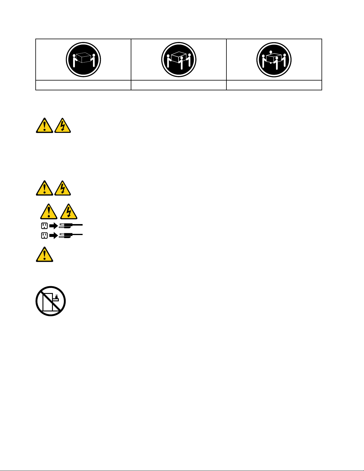
≥18kg(37lbs)≥32kg(70.5lbs)≥55kg(121.2lbs)
1
2
CAUTION:
Usesafepracticeswhenlifting.
CAUTION:
Thepowercontrolbuttononthedeviceandthepowerswitchonthepowersupplydonotturnoff
theelectricalcurrentsuppliedtothedevice.Thedevicealsomighthavemorethanonepower
cord.Toremoveallelectricalcurrentfromthedevice,ensurethatallpowercordsaredisconnected
fromthepowersource.
CAUTION:
Donotplaceanyobjectweighingmorethan82kg(180lbs.)ontopofrack-mounteddevices.
8LenovoC355/C455All-In-OneComputerHardwareMaintenanceManual
Page 15

Chapter3.Generalinformation
Thischapterprovidesgeneralinformationthatappliestoallcomputermodelscoveredbythismanual.
Specications
Thissectionliststhephysicalspecicationsforyourcomputer.
Thissectionliststhephysicalspecicationsforyourcomputer.
TypeLenovoC355/C455
Thissectionliststhephysicalspecications.
Environment
Airtemperature:
Operating:10°to35°C
Transit:-20°to55°C
Humidity:
Operating:35%to80%
Transit:20%to90%(40°C)
Altitude:86KPato106KPa
Electricalinput:
Inputvoltage:90V-264V(AC)
Inputfrequency:47Hz-63Hz
©CopyrightLenovo2013
9
Page 16

10LenovoC355/C455All-In-OneComputerHardwareMaintenanceManual
Page 17

Chapter4.GeneralCheckout
Attention:Thedrivesinthecomputeryouareservicingmighthavebeenrearrangedorthedrivestartup
sequencemayhavebeenchanged.Beextremelycarefulduringwriteoperationssuchascopying,saving,or
formatting.Dataorprogramscanbeoverwrittenifyouselectanincorrectdrive.
Generalerrormessagesappearifaproblemorconictisfoundbyanapplication,theoperatingsystem,or
both.Foranexplanationofthesemessages,refertotheinformationsuppliedwiththatsoftwarepackage.
Usethefollowingproceduretohelpdeterminethecauseoftheproblem:
1.Power-offthecomputerandallexternaldevices.
2.Checkallcablesandpowercords.
3.Setalldisplaycontrolstothemiddleposition.
4.Power-onallexternaldevices.
5.Power-onthecomputer.
•Lookfordisplayederrorcodes.
•Lookforreadableinstructionsoramainmenuonthedisplay.
Ifyoudidnotreceivethecorrectresponse,proceedtostep6.
Ifyoudidreceivethecorrectresponse,proceedtostep7.
6.Ifoneofthefollowinghappens,followtheinstructiongiven:
•IfthecomputerdisplaysaPOSTerror,goto“POSTerrorcodes” .
•Ifthecomputerhangsandnoerrorisdisplayed,continueatstep7.
7.Iftheteststopsandyoucannotcontinue,replacethelastdevicetested.
©CopyrightLenovo2013
11
Page 18

12LenovoC355/C455All-In-OneComputerHardwareMaintenanceManual
Page 19

Chapter5.UsingtheSetupUtility
TheSetupUtilityprogramisusedtoviewandchangethecongurationsettingsofyourcomputer,regardless
ofwhichoperatingsystemyouareusing.However,theoperatingsystemsettingsmightoverrideanysimilar
settingsintheSetupUtilityprogram.
StartingtheLenovoBIOSSetupUtilityprogram
TostarttheLenovoBIOSSetupUtilityprogram,dothefollowing:
1.Ifyourcomputerisalreadyonwhenyoustartthisprocedure,shutdowntheoperatingsystemand
turnoffthecomputer.
2.PressandholdtheF1keythenturnonthecomputer.WhentheLenovoBIOSSetupUtilityprogramis
displayed,releasetheF1key.
Note:IfaPower-OnPasswordoranAdministratorPasswordhasbeenset,theSetupUtilityprogrammenu
willnotbedisplayeduntilyoutypeyourpassword.Formoreinformation,see“Usingpasswords. ”
Viewingandchangingsettings
SystemcongurationoptionsarelistedintheLenovoBIOSSetupUtilityprogrammenu.T ovieworchange
settings,see“StartingtheSetupUtilityprogram.”
YoumustusethekeyboardwhenusingtheLenovoBIOSSetupUtilitymenu.Thekeysusedtoperform
varioustasksaredisplayedonthebottomofeachscreen.
Usingpasswords
YoucanusetheLenovoBIOSSetupUtilityprogramtosetpasswordstopreventunauthorizedpersons
fromgainingaccesstoyourcomputeranddata.See“StartingtheSetupUtilityprogram. ”Thefollowing
typesofpasswordsareavailable:
•AdministratorPassword
•Power-OnPassword
Youdonothavetosetanypasswordstouseyourcomputer.However,ifyoudecidetosetpasswords,read
thefollowingsections.
Passwordconsiderations
Apasswordcanbeanycombinationoflettersandnumbersupto16characters(a-zand0-9).Forsecurity
reasons,itisagoodideatouseastrongpasswordthatcannotbeeasilycompromised.Wesuggestthat
passwordsshouldfollowtheserules:
•Forastrongpassword,use7-16charactersandamixoflettersandnumbers.
•Donotuseyournameoryourusername.
•Donotuseacommonwordoracommonname.
•Usesomethingsignicantlydifferentfromyourpreviouspassword.
Attention:AdministratorandPower-Onpasswordsarenotcasesensitive.
©CopyrightLenovo2013
13
Page 20

AdministratorPassword
SettinganAdministratorPassworddetersunauthorizedpersonsfromchangingcongurationsettings.Y ou
mightwanttosetanAdministratorPasswordifyouareresponsibleformaintainingthesettingsofseveral
computers.
AfteryousetanAdministratorPassword,apasswordpromptisdisplayedeverytimeyouaccesstheLenovo
BIOSSetupUtilityprogram.
IfboththeAdministratorandPower-OnPasswordareset,youcantypeeitherpassword.However,youmust
useyourAdministratorPasswordtochangeanycongurationsettings.
Setting,changing,ordeletinganAdministratorpassword
TosetanAdministratorPassword,dothefollowing:
Note:Apasswordcanbeanycombinationoflettersandnumbersupto16characters(a-zand0-9).For
moreinformation,see“Passwordconsiderations”onpage13.
1.StarttheLenovoBIOSSetupUtilityprogram(see“StartingtheLenovoBIOSSetupUtilityprogram”on
page13).
2.FromtheSecuritymenu,selectSetAdministratorPasswordandpresstheEnterkey.
3.Thepassworddialogboxwillbedisplayed.T ypethepasswordthenpresstheEnterkey.
4.Re-typethepasswordtoconrm,thenpresstheEnterkey.Ifyoutypedthepasswordcorrectly,
thepasswordwillbeinstalled.
TochangeanAdministratorPassword,dothefollowing:
1.StarttheLenovoBIOSSetupUtilityprogram(see“StartingtheLenovoBIOSSetupUtilityprogram”on
page13).
2.FromtheSecuritymenu,selectSetAdministratorPasswordandpresstheEnterkey.
3.Thepassworddialogboxwillbedisplayed.T ypethecurrentpasswordthenpresstheEnterkey.
4.T ypethenewpassword,thenpresstheEnterkey.Re-typethepasswordtoconrmthenewpassword.
Ifyoutypedthenewpasswordcorrectly,thenewpasswordwillbeinstalled.ASetupNoticedconrming
thatchangeshavebeensavedwillbedisplayed.
TodeleteapreviouslysetAdministratorPassword,dothefollowing:
1.FromtheSecuritymenu,selectSetAdministratorPasswordandpresstheEnterkey.
2.Thepassworddialogboxwillbedisplayed.T ypethecurrentpasswordandpresstheEnterkey.
3.T odeleteanAdministratorPassword,leaveeachnewpasswordlineitemblank,thenpresstheEnter
key.ASetupNoticeconrmingthatchangeshavebeensavedwillbedisplayed.
4.ReturntotheLenovoBIOSSetupUtilityprogrammenuandselecttheExitoption.
5.SelectSavechangesandExitfromthemenu.
Power-OnPassword
WhenaPower-OnPasswordisset,youcannotstarttheLenovoBIOSSetupUtilityprogramuntilavalid
passwordistypedfromthekeyboard.
Setting,changing,ordeletingaPower-OnPassword
Note:Apasswordcanbeanycombinationoflettersandnumbersupto16characters(a-zand0-9).
14LenovoC355/C455All-In-OneComputerHardwareMaintenanceManual
Page 21

TosetaPower-OnPassword,dothefollowing:
1.StarttheLenovoBIOSSetupUtilityprogram(See”StartingtheLenovoBIOSSetupUtilityprogram”on
page13.)
2.FromtheSecuritymenu,selectSetPower-OnPasswordandpresstheEnterkey.
3.Thepassworddialogboxwillbedisplayed.T ypethepassword,thenpresstheEnterkey.
4.Re-typethepasswordtoconrm.Ifyoutypedthepasswordcorrectly,thepasswordwillbeinstalled.
TochangeaPower-OnPassword,dothefollowing:
1.StarttheLenovoBIOSSetupUtilityprogram(See”StartingtheLenovoBIOSSetupUtilityprogram”on
page13.)
2.FromtheSecuritymenu,selectSetPower-OnPasswordandpresstheEnterkey.
3.Thepassworddialogboxwillbedisplayed.T ypethecurrentpasswordthenpresstheEnterkey.
4.T ypethenewpassword,thenpresstheEnterkey.Re-typethepasswordtoconrmthenewpassword.
Ifyoutypedthenewpasswordcorrectly,thenewpasswordwillbeinstalled.ASetupNoticedconrming
thatchangeshavebeensavedwillbedisplayed.
TodeleteapreviouslysetPower-OnPassword,dothefollowing:
1.FromtheSecuritymenu,selectSetPower-OnPasswordandpresstheEnterkey.
2.Thepassworddialogboxwillbedisplayed.T ypethecurrentpasswordandpresstheEnterkey.
3.T odeletethePower-OnPassword,leaveeachnewpasswordlineitemblank,thenpressEnter.ASetup
Noticeconrmingthatchangeshavebeensavedwillbedisplayed.
4.ReturntotheLenovoBIOSSetupUtilityprogrammenuandselecttheExitoption.
5.SelectSavechangesandExitfromthemenu.
Enablingordisablingadevice
TheDevicesoptionsisusedtoenableordisableuseraccesstothefollowingdevices:
USBFunctionsSelectwhethertoenableordisableUSB(UniversalSerial
Bus)functions.Ifthefunctionsaredisabled,noUSB
devicescanbeused.
SATAMode
OnboardAudioControllerSelectwhethertoenableordisabletheOnboard
OnboardEthernetControllerorLANBootAgentSelectwhethertoenableordisabletheOnboardEthernet
Toenableordisableadevice,dothefollowing:
1.StarttheSetupUtilityprogram(see“StartingtheSetupUtilityprogram”onpage13).
2.FromtheSetupUtilityprogrammenu,selectDevices.
3.Selectanoptionasfollows:
WhenthisfeatureissettoDisabled,alldevices
connectedtotheSATAconnectors(e.g.harddiskdrives
ortheopticaldiskdrive)aredisabledandcannotbe
accessed.
AudioController.WhenthisfeatureissettoDisabled
alldevicesconnectedtotheaudioconnectors(e.g.
headphonesoramicrophone)aredisabledandcannot
beused.
Controller,orselectwhethertoenableordisableload
onboardPXE(PrebootExecutionEnvironment).
SelectUSBSetup,presstheEnterkey,thenselectUSBFunctions.
Chapter5.UsingtheSetupUtility15
Page 22

SelectA T ADeviceSetup,presstheEnterkey,thenselectSA T AMode.
SelectAudioSetup,presstheEnterkey,thenselectOnboardAudioController.
SelectNetworkSetup,presstheEnterkey,thenselectOnboardEthernetSupportorLANBoot
Agent.
4.SelectDisabledorEnabledandpresstheEnterkey.
5.ReturntotheLenovoBIOSSetupUtilityprogrammenuandselecttheExitoption.
6.SelectSavechangesandExitfromthemenu.
Notes:
a.Ifyoudonotwanttosavethesettings,selectDiscardchangesandExitfromthemenu.
b.SelectIDE/AHCIMode:DevicedriversupportisrequiredforACHI.Dependingonhowtheharddisk
imagewasinstalled,changingthissettingmaypreventthesystemfrombooting.
Selectingastartupdevice
IfyourcomputerdoesnotbootfromadevicesuchastheCD/DVD-ROMdrivediskorharddiskasexpected,
followoneoftheproceduresbelow.
Selectingatemporarystartupdevice
Usethisproceduretostartupfromanybootdevice.
Note:NotallCDs,DVDsorharddiskdrivesarebootable.
1.T urnoffyourcomputer.
2.PressandholdtheF12keythenturnonthecomputer.WhentheStartupDeviceMenuappears,
releasetheF12key.
Note:IftheStartupDeviceMenudoesnotdisplayusingthesesteps,repeatedlypressandreleasethe
F12keyratherthankeepingitpressedwhenturningonthecomputer.
3.Use↑and↓arrowstoselectthedesiredstartupdevicefromtheStartupDeviceMenuandpress
theEnterkeytobegin.
Note:SelectingastartupdevicefromtheStartupDeviceMenudoesnotpermanentlychangethe
startupsequence.
Selectingorchangingthestartupdevicesequence
Tovieworpermanentlychangetheconguredstartupdevicesequence,dothefollowing:
1.StarttheLenovoBIOSSetupUtilityprogram(see“StartingtheLenovoBIOSSetupUtilityprogram”on
page13).
2.FromtheLenovoBIOSSetupUtilityprogrammainmenu,selecttheStartupoption.
3.PresstheEnterkey,andselectthedevicesforthePrimaryBootSequence.Readtheinformation
displayedontherightsideofthescreen.
4.Use↑and↓arrowstoselectadevice.Usethe<+>or<->keystomoveadeviceupordown.Usethe
<×>keytoexcludethedevicefromorincludethedeviceinthebootsequence.
5.ReturntotheLenovoBIOSSetupUtilityprogrammenuandselecttheExitoption.
6.SelectSavechangesandExitfromthemenu.
Notes:
16LenovoC355/C455All-In-OneComputerHardwareMaintenanceManual
Page 23

a.Ifyoudonotwanttosavethesettings,selectDiscardchangesandExitfromthemenu.
b.Ifyouhavechangedthesesettingsandwanttoreturntothedefaultsettings,selectLoadOptimal
Defaultsfromthemenu.
ExitingtheLenovoBIOSSetupUtilityprogram
Afteryounishviewingorchangingsettings,presstheEsckeytoreturntotheLenovoBIOSSetupUtility
programmainmenu.Y oumighthavetopresstheEsckeyseveraltimes.Dooneofthefollowing:
•Ifyouwanttosavethenewsettings,selectSavechangesandExitfromthemenu.WhentheSave&
resetwindowshows,selecttheYesbutton,andthenpresstheEnterkeytoexittheLenovoBIOS
SetupUtilityprogram.
•Ifyoudonotwanttosavethesettings,selectDiscardchangesandExitfromthemenu.Whenthe
ResetWithoutSavingwindowshows,selecttheY esbutton,andthenpresstheEnterkeytoexitthe
LenovoBIOSSetupUtilityprogram.
Chapter5.UsingtheSetupUtility17
Page 24

18LenovoC355/C455All-In-OneComputerHardwareMaintenanceManual
Page 25
Chapter6.Symptom-to-FRUIndex
TheSymptom-to-FRUindexlistserrorsymptomsandpossiblecauses.Themostlikelycauseislistedrst.
AlwaysbeginwithChapter4,“GeneralCheckout,”onpage11.Thisindexcanalsobeusedtohelpyou
decidewhichFRUstohaveavailablewhenservicingacomputer.Ifyouareunabletocorrecttheproblem
usingthisindex,goto“Undeterminedproblems”onpage20.
Notes:
•Ifyouhavebothanerrormessageandanincorrectaudioresponse,diagnosetheerrormessagerst.
•Ifyoucannotrunthediagnostictestsoryougetadiagnosticerrorcodewhenrunningatestbutdid
receiveaPOSTerrormessage,diagnosethePOSTerrormessagerst.
•Ifyoudidnotreceiveanyerrormessagelookforadescriptionofyourerrorsymptomsintherstpartof
thisindex.
Harddiskdrivebooterror
Aharddiskdrivebooterrorcanbecausedbythefollowing.
Error
Thestartupdriveisnotincludedinthebootsequence
conguration.
Nooperatingsystemisinstalledonthebootdrive.Installanoperatingsystemonthebootdrive.
Thebootsectoronthestartupdriveiscorrupted.
Thedriveisdefective.
FRU/Action
Checkthecongurationandensurethestartupdriveis
inthebootsequence.
Thedrivemustbeformatted.Dothefollowing:
1.Attempttobackupthedataonthefailingharddisk
drive.
2.Usetheoperatingsystemtoformattheharddisk
drive.
Replacetheharddiskdrive.
PowerSupplyProblems
Followtheseproceduresifyoususpectthereisapowersupplyproblem.
Check/VerifyFRU/Action
Checkthatthefollowingareproperlyinstalled:
•PowerCord
•On/OffSwitchconnector
•SystemBoardPowerSupplyconnectors
•Microprocessorconnections
Checkthepowercord.PowerCord
Checkthepower-onswitch.Power-onSwitch
Reseatconnectors
©CopyrightLenovo2013
19
Page 26

POSTerrorcodes
Eachtimeyouturnthecomputeron,itperformsaseriesofteststocheckthatthesystemisoperating
correctlyandthatcertainoptionsareset.ThisseriesoftestsiscalledthePower-OnSelf- T est,orPOST.
POSTdoesthefollowing:
•Checkssomebasicmotherboardoperations
•Checksthatthememoryisworkingcorrectly
•Startsvideooperations
•Veriesthatthebootdriveisworking
POSTErrorMessageDescription/Action
Keyboarderror
RebootandSelectproperBootdeviceorInsertBoot
MediainselectedBootdevice
Cannotinitializethekeyboard.Makesurethekeyboard
isproperlyconnectedtothecomputerandthatnokeys
areheldpressedduringPOST.Topurposelycongure
thecomputerwithoutakeyboard,selectKeyboardless
operationinStartupandsettheoptiontoEnabled.The
BIOSthenignoresthemissingkeyboardduringPOST.
TheBIOSwasunabletondasuitablebootdevice.Make
surethebootdriveisproperlyconnectedtothecomputer.
Makesureyouhavebootablemediainthebootdevice.
Undeterminedproblems
1.Power-offthecomputer.
2.Removeordisconnectthefollowingcomponents(ifconnectedorinstalled)oneatatime.
a.Externaldevices(modem,printer,ormouse)
b.Extendedvideomemory
c.ExternalCache
d.ExternalCacheRAM
e.Harddiskdrive
f.Diskdrive
3.Power-onthecomputertore-testthesystem.
4.Repeatsteps1through3untilyoundthefailingdeviceorcomponent.
Ifalldevicesandcomponentshavebeenremovedandtheproblemcontinues,replacethesystemboard.
20LenovoC355/C455All-In-OneComputerHardwareMaintenanceManual
Page 27

Chapter7.Locatingconnectors,controlsandcomponents
1 2
3 7654 8 9
10
Thissectionprovidesillustrationstohelplocatethevariousconnectors,controlsandcomponentsofthe
computer.
Fontview
Thefollowingillustrationshowsthelocationofcontrolsandcomponentsonthefrontofthecomputer.
Attention:Becarefulnottoblockanyairventsonthecomputer.Blockedairventscancauseoverheating.
1.Built-inmicrophone6.Menubutton
2.Built-incamera
3.Harddiskdriveindicator8.Rightdirectionbutton
4.Wi-Fistatusindicator
5.MonitorOn/Offindicator10.Built-inIRreceiver(Onlyfunctionalonmodels
©CopyrightLenovo2013
7.Leftdirectionbutton
9.MonitorOn/Offbutton
equippedwithaIRreceivermodule)
21
Page 28

Leftandrightview
1
2
3
6
5
4
7
8
Thefollowingillustrationshowsthelocationofconnectors,controlsandcomponentsontheleftandright
sideofthecomputer.
1.USBconnector
5.Memorycardreader
2.Headphoneconnector6.Powerbutton
3.Microphoneconnector
7.Opticaldriveejectbutton
4.USBconnector8.Opticaldrive
Attention:Donotinsert3-inchdiscsintotheopticaldrive.
22LenovoC355/C455All-In-OneComputerHardwareMaintenanceManual
Page 29

Rearview
1 2 3 7654
8
9
Thefollowingillustrationshowsthelocationofconnectorsandcomponentsontherearofthecomputer.
1.TVtunerconnector(selectedmodelsonly,2connectors
forJapan)
2.TVtunerconnector(selectedmodelsonly,2connectors
forJapan)
3.Powerconnector
4.Ethernetconnector9.Airvents
5.USBconnector
6.USBconnector
7.HDMI-outconnector(selectedmodelsonly)
8.Securitycableslot
Chapter7.Locatingconnectors,controlsandcomponents23
Page 30

Hardwarecomponents
1
2
3
7
8
9
10
11
12
14
13
15
16
17
18
19
20
21
22
5
6
4
Thefollowingillustrationshowsthecomponentsthatmakeupyourcomputer.
1.Opticaldiskdrivebracket
2.Opticaldiskdrive
3.Harddiskdrivebracket14.Wi-Ficard
4.Harddiskdrive15.TV- T unercard
5.Heat-sink
6.Systemfan17.B-CAScardreader
7.Speakers
8.RearI/Omodulebracket
9.RearI/Omodule
10.Chassis
11.LEDpanel
12.Frontbezel
13.Memorymodule
16.Converterboard
18.Motherboard
19.EMIcover
20.Footcover
21.Middlecover
22.Computerstand
24LenovoC355/C455All-In-OneComputerHardwareMaintenanceManual
Page 31

Identifyingpartsonthemotherboard
1
2
3
6
7
8
9
10
11 12 13
14
15 16 17
18
4
5
Themotherboard(sometimescalledtheplanarorsystemboard)isthemaincircuitboardinyourcomputer.
Itprovidesbasiccomputingfunctionsandsupportsavarietyofdevicesthatarefactory-installedorthat
youcaninstalllater.Thefollowingillustrationshowsthelocationofconnectorsandcomponentsonthe
frontofthemotherboard.
1.Cameraconnector10.DC-inconnector
2.Opticaldiskdrivepowerconnector11.RearI/Omoduleconnector
3.Systemfanconnector
12.TV-T unercardconnector
4.LVDSconnector13.B-CAScardreaderconnector
5.OpticaldriveSATAconnector
6.Battery
7.HarddiskdriveSATAconnector
8.Harddiskdrivepowerconnector
9.Converterconnector
14.Wi-Ficardconnector
15.F rontfunctionboardconnector
16.Powercontrolconnector
17.Speakerconnector
18.Memoryconnector
Chapter7.Locatingconnectors,controlsandcomponents25
Page 32

26LenovoC355/C455All-In-OneComputerHardwareMaintenanceManual
Page 33

Chapter8.Replacinghardware
Attention:Donotremovethecomputercoverorattemptanyrepairbeforereadingthe“Importantsafetyinformation”
intheSafetyandWarrantyGuidethatwasincludedwithyourcomputer.ToobtaincopiesoftheSafetyandWarranty
Guide,gototheSupportWebsiteat:http://consumersupport.lenovo.com.
Note:UseonlypartsprovidedbyLenovo.
Generalinformation
Pre-disassemblyinstructions
Beforestartingthedisassemblyprocedure,makesurethatyoudothefollowing:
1.T urnoffthepowertothesystemandallperipherals.
2.Unplugallpowerandsignalcablesfromthecomputer.
3.Placethesystemonaat,stablesurface.
©CopyrightLenovo2013
27
Page 34

Replacingthekeyboardandmouse
Note:Y ourkeyboardwillbeconnectedtoaUSBconnectorateithersideorattherearofthecomputer.
Toreplacethekeyboard:
Step1.Removeanymedia(disks,CDs,ormemorycards)fromthedrives,shutdownthecomputer,and
turnoffallattacheddevices.
Step2.Unplugallpowercordsfromelectricaloutlets.
Step3.Locatetheconnectorforthekeyboard.Referto“Sideviewofthecomputer”and“Rearviewof
thecomputer”.
Step4.Disconnectthedefectivekeyboardcablefromthecomputerandconnectthenewkeyboardcable
tothesameconnector.
Step5.Themousecanbereplacedusingthesamemethod.
Replacingtheadapter
Attention:T urnoffthecomputerandwait3to5minutestoletitcooldownbeforeremovingthecover.
Step1.Removeanymedia(disks,CDs,ormemorycards)fromthedrives,shutdowntheoperating
system,andturnoffthecomputerandallattacheddevices.
28LenovoC355/C455All-In-OneComputerHardwareMaintenanceManual
Page 35

Step2.Disconnecttheadaptercablefromthecomputer1,thenunplugthepowercordfromelectrical
outlet.2
Step3.Connectthenewadapterasshown.12
Chapter8.Replacinghardware29
Page 36

Removingthestandbase
Attention:T urnoffthecomputerandwait3to5minutestoletitcooldownbeforeremovingthecover.
Note:Itmaybehelpfultoplacethecomputerface-downonasoftatsurfaceforthisprocedure.Lenovo
recommendsthatyouuseablanket,towel,orothersoftclothtoprotectthetouchscreenfromscratches
orotherdamage.
Step1.Removeanymedia(disks,CDs,ormemorycards)fromthedrives,shutdowntheoperating
system,andturnoffthecomputerandallattacheddevices.
Step2.Unplugallpowercordsfromelectricaloutlets.
Step3.Disconnectallcablesattachedtothecomputer.Thisincludespowercords,input/output(I/O)
cables,andanyothercablesthatareconnectedtothecomputer.Referto“Leftandrightviews”
and“Rearview”forhelpwithlocatingthevariousconnectors.
Step4.Twistthehandscrewringcounter-clockwiseuntilthebasecomesloosetoreleasethestandbase
fromthestandholder.1
Step5.Slidethestandbaseoutfromtheholderthenputitaside.2
Step6.Referto“Installingthecomputerstand”toreinstallthestandbase.
Removingthefootcover
Attention:T urnoffthecomputerandwait3to5minutestoletitcooldownbeforeremovingthecover.
30LenovoC355/C455All-In-OneComputerHardwareMaintenanceManual
Page 37

Note:Itmaybehelpfultoplacethecomputerface-downonasoftatsurfaceforthisprocedure.Lenovo
recommendsthatyouuseablanket,towel,orothersoftclothtoprotectthetouchscreenfromscratches
orotherdamage.
Step1.Removeanymedia(disks,CDs,ormemorycards)fromthedrives,shutdowntheoperating
system,andturnoffthecomputerandallattacheddevices.
Step2.Unplugallpowercordsfromelectricaloutlets.
Step3.Disconnectallcablesattachedtothecomputer.Thisincludespowercords,input/output(I/O)
cables,andanyothercablesthatareconnectedtothecomputer.Referto“Leftandrightviews”
and“Rearview”forhelpwithlocatingthevariousconnectors.
Step4.Removethefootbase.Referto“Removingthefootbase” .
Step5.Liftupthestandholderthenslideoutthefootcoverasshown.
Step6.Toreattachthefootcover:
a.Liftupthestandholder.
b.Lineupthefootcoverwithmountingholesonthebackofthecomputer,thenslideitbackinto
position.
Replacingamemorymodule
Attention:T urnoffthecomputerandwait3to5minutestoletitcooldownbeforeremovingthecover.
Chapter8.Replacinghardware31
Page 38

Note:Itmaybehelpfultoplacethecomputerface-downonasoftatsurfaceforthisprocedure.Lenovo
recommendsthatyouuseablanket,towel,orothersoftclothtoprotectthetouchscreenfromscratches
orotherdamage.
Step1.Removeanymedia(disks,CDs,ormemorycards)fromthedrives,shutdowntheoperating
system,andturnoffthecomputerandallattacheddevices.
Step2.Unplugallpowercordsfromelectricaloutlets.
Step3.Disconnectallcablesattachedtothecomputer.Thisincludespowercords,input/output(I/O)
cables,andanyothercablesthatareconnectedtothecomputer.Referto“Leftandrightviews”
and“Rearview”forhelpwithlocatingthevariousconnectors.
Step4.Removethestandbase.Referto“Removingthestandbase” .
Step5.Removethefootcover.Referto“Removingthefootcover”.
Step6.Pushoutthelatchesonbothsidesofthememorysockettoreleasethememorymodule1and
gentlypullthememorymoduleupwardtoremoveitfromitssocket.2Allofthememorymodules
canberemovedusingthesameprocedure.
Step7.Toinstallamemorymodule:
a.Alignthenewmemorymodulewiththememorysocket,theninsertitandpushdownonthe
topedge.Makesurethelatcheslockthememorymoduleinplace.
Step8.Reattachthefootcoverandstandbase.
32LenovoC355/C455All-In-OneComputerHardwareMaintenanceManual
Page 39

Replacingtheharddiskdrive
1
1
Attention:T urnoffthecomputerandwait3to5minutestoletitcooldownbeforeremovingthecover.
Note:Itmaybehelpfultoplacethecomputerface-downonasoftatsurfaceforthisprocedure.Lenovo
recommendsthatyouuseablanket,towel,orothersoftclothtoprotectthetouchscreenfromscratches
orotherdamage.
Step1.Removeanymedia(disks,CDs,ormemorycards)fromthedrives,shutdowntheoperating
system,andturnoffthecomputerandallattacheddevices.
Step2.Unplugallpowercordsfromelectricaloutlets.
Step3.Disconnectallcablesattachedtothecomputer.Thisincludespowercords,input/output(I/O)
cables,andanyothercablesthatareconnectedtothecomputer.Referto“Leftandrightviews”
and“Rearview”forhelpwithlocatingthevariousconnectors.
Step4.Removethestandbase.Referto“Removingthestandbase” .
Step5.Removethefootcover.Referto“Removingthefootcover”.
Step6.Pushtheharddiskdrivebracket1,thenslidetheharddiskdriveandbracketoutofthechassisas
shown.2
Chapter8.Replacinghardware33
Page 40

Step7.Pushthelockpinsoutwardtoreleasetheharddiskdrivefromthebracket.
Step8.Toinstallthenewharddiskdrive:
a.Lineupthenewharddiskdrivewiththebracketandsecureitwiththepins.
b.Slidetheharddiskdriveandbracketbackintoposition.
Step9.Reattachthefootcoverandstandbase.
Replacingtheopticaldrive
Attention:T urnoffthecomputerandwait3to5minutestoletitcooldownbeforeremovingthecover.
Note:Itmaybehelpfultoplacethecomputerface-downonasoftatsurfaceforthisprocedure.Lenovo
recommendsthatyouuseablanket,towel,orothersoftclothtoprotectthetouchscreenfromscratches
orotherdamage.
Step1.Removeanymedia(disks,CDs,ormemorycards)fromthedrives,shutdowntheoperating
system,andturnoffthecomputerandallattacheddevices.
Step2.Unplugallpowercordsfromelectricaloutlets.
Step3.Disconnectallcablesattachedtothecomputer.Thisincludespowercords,input/output(I/O)
cables,andanyothercablesthatareconnectedtothecomputer.Referto“Leftandrightviews”
and“Rearview”forhelpwithlocatingthevariousconnectors.
Step4.Removethestandbase.Referto“Removingthestandbase” .
Step5.Removethefootcover.Referto“Removingthefootcover”.
34LenovoC355/C455All-In-OneComputerHardwareMaintenanceManual
Page 41

Step6.Pushtheopticaldrivepindownwardtopushouttheopticaldriveasshown.12
Step7.Pushasmallironstick(paperclip)intothesmallholeontheopticaldrivecoversothatthedisk
springsoutasshown.
Step8.Removethe2screwsthatsecuretheopticaldrivetothemetalbracket.1
Step9.Useasmallatheadscrewdrivertopressandpushoutthepinsthatsecurethecovertothe
disk.23
Chapter8.Replacinghardware35
Page 42

Step10.Separatethecoverfromthedefectiveopticaldrive.
Step11.Toinstallthenewopticaldrive:
a.Alignthenewopticaldrivewiththecover,andthenpushthecoverbackintoposition.
b.Screwthemetalbracketbackontothenewopticaldrive.
c.Slidethenewopticaldriveintothedrivebay.
Step12.Reattachthefootcoverandstandbase.
Removingthestandholder
Note:Turnoffthecomputerandwait3to5minutestoletitcooldownbeforeremovingthecover.
Note:Itmaybehelpfultoplacethecomputerface-downonasoftatsurfaceforthisprocedure.Lenovo
recommendsthatyouuseablanket,towel,orothersoftclothtoprotectthecomputerscreenfromscratches
orotherdamage.
Toremovethestandholder:
Step1.Removeanymedia(disks,CDs,DVDs,ormemorycards)fromthedrives,shutdowntheoperating
system,andturnoffthecomputerandallattacheddevices.
Step2.Unplugallpowercordsfromelectricaloutlets.
Step3.Disconnectallcablesattachedtothecomputer.Thisincludespowercords,input/output(I/O)
cables,andanyothercablesthatareconnectedtothecomputer.Referto“Leftandrightview”
and“Rearview”forhelpwithlocatingthevariousconnectors.
Step4.Removethestandbase.Referto“Removingthestandbase” .
Step5.Removethefootcover.Referto“Removingthefootcover”.
Step6.Removethefourscrewsthatsecurethestandholdertothechassis,thenliftupthestandholderto
removeit.
36LenovoC355/C455All-In-OneComputerHardwareMaintenanceManual
Page 43

Step7.Toreattachthestandholder:
a.Aligntheholesonthestandholderwithmountingholesonthechassis,placethestand
holderbackintoposition.
b.Securethestandholdertothechassiswiththefourscrews.
Step8.Lineupthefootcoverwithmountingholesonthebackofthecomputer,thenslideitbackinto
position.
Step9.Reattachthestandbase.
Removingthemiddlecover
Note:Turnoffthecomputerandwait3to5minutestoletitcooldownbeforeremovingthecover.
Note:Itmaybehelpfultoplacethecomputerface-downonasoftatsurfaceforthisprocedure.Lenovo
recommendsthatyouuseablanket,towel,orothersoftclothtoprotectthecomputerscreenfromscratches
orotherdamage.
Toremovethemiddlecover:
Step1.Removeanymedia(disks,CDs,DVDs,ormemorycards)fromthedrives,shutdowntheoperating
system,andturnoffthecomputerandallattacheddevices.
Step2.Unplugallpowercordsfromelectricaloutlets.
Step3.Disconnectallcablesattachedtothecomputer.Thisincludespowercords,input/output(I/O)
cables,andanyothercablesthatareconnectedtothecomputer.Referto“Leftandrightview”
and“Rearview”forhelpwithlocatingthevariousconnectors.
Step4.Removethestandbase.Referto“Removingthestandbase” .
Step5.Removethefootcover.Referto“Removingthefootcover”.
Step6.Removetheopticaldrive.Referto“Replacingtheopticaldrive” .
Step7.Removethestandholder.Referto“Removingthestandholder”.
Step8.Removethesevenscrewsthatsecurethemiddlecovertothechassis,thenliftupthemiddlecover
fromtheleftside(opticaldriveside)toremovethemiddlecover.
Chapter8.Replacinghardware37
Page 44

Step9.Toreattachthemiddlecover:
a.Lineupthemiddlecoverwithchassis,thenplacethemiddlecoverback.
b.Securethemiddlecovertothechassiswiththesevenscrews.
Step10.Reattachthestandholder,opticaldrive,footcoverandstandbase.
Replacingtheconverterboard
Note:Turnoffthecomputerandwait3to5minutestoletitcooldownbeforeremovingthecover.
Note:Itmaybehelpfultoplacethecomputerface-downonasoftatsurfaceforthisprocedure.Lenovo
recommendsthatyouuseablanket,towel,orothersoftclothtoprotectthecomputerscreenfromscratches
orotherdamage.
Toreplacetheconverterboard:
Step1.Removeanymedia(disks,CDs,DVDs,ormemorycards)fromthedrives,shutdowntheoperating
system,andturnoffthecomputerandallattacheddevices.
Step2.Unplugallpowercordsfromelectricaloutlets.
Step3.Disconnectallcablesattachedtothecomputer.Thisincludespowercords,input/output(I/O)
cables,andanyothercablesthatareconnectedtothecomputer.Referto“Leftandrightview”
and“Rearview”forhelpwithlocatingthevariousconnectors.
Step4.Removethestandbase.Referto“Removingthestandbase” .
Step5.Removethefootcover.Referto“Removingthefootcover”.
Step6.Removetheopticaldrive.Referto“Replacingtheopticaldrive” .
Step7.Removethestandholder.Referto“Removingthestandholder”.
Step8.Removethemiddlecover.Referto“Removingthemiddlecover” .
38LenovoC355/C455All-In-OneComputerHardwareMaintenanceManual
Page 45

Step9.Disconnectthetwocablesfromtheconverter,andthenremovethetwoscrewsthatsecurethe
converterboardtothechassis.
Step10.Liftuptheconverterboardtoremoveit.
Step11.Toinstallthenewconverterboard:
a.Lineuptheholesonthenewconverterboardwiththemountingholesonthechassisand
secureitwiththetwoscrews.
b.Connectthetwocablestothenewconverterboard.
Step12.Reattachthemiddlecover,opticaldrive,standholder,footcoverandstandbase.
Replacingthecamera
Note:Turnoffthecomputerandwait3to5minutestoletitcooldownbeforeremovingthecover.
Note:Itmaybehelpfultoplacethecomputerface-downonasoftatsurfaceforthisprocedure.Lenovo
recommendsthatyouuseablanket,towel,orothersoftclothtoprotectthecomputerscreenfromscratches
orotherdamage.
Toreplacethecamera:
Step1.Removeanymedia(disks,CDs,DVDs,ormemorycards)fromthedrives,shutdowntheoperating
system,andturnoffthecomputerandallattacheddevices.
Step2.Unplugallpowercordsfromelectricaloutlets.
Step3.Disconnectallcablesattachedtothecomputer.Thisincludespowercords,input/output(I/O)
cables,andanyothercablesthatareconnectedtothecomputer.Referto“Leftandrightview”
and“Rearview”forhelpwithlocatingthevariousconnectors.
Step4.Removethestandbase.Referto“Removingthestandbase” .
Step5.Removethefootcover.Referto“Removingthefootcover”.
Step6.Removetheopticaldrive.Referto“Replacingtheopticaldrive” .
Step7.Removethestandholder.Referto“Removingthestandholder”.
Step8.Removethemiddlecover.Referto“Removingthemiddlecover” .
Step9.Removetheheat-sink.Referto“Replacingtheheatsink” .
Chapter8.Replacinghardware39
Page 46

Step10.Removethetwoscrewsthatsecurecameratothefrontbezel.1
Step11.Liftupthecamera2anddisconnectthedatacablefromthecamera.3
Step12.Toinstallthenewcamera:
a.Connectthedatacabletothenewcamera.
b.Lineuptheholesinthenewcamerawiththemountingholesonthefrontbezelandsecureit
withthetwoscrews.
Step13.Reattachthemiddlecover,opticaldrive,standholder,footcoverandstandbase.
RemovingtheEMIcover
Note:Turnoffthecomputerandwait3to5minutestoletitcooldownbeforeremovingthecover.
Note:Itmaybehelpfultoplacethecomputerface-downonasoftatsurfaceforthisprocedure.Lenovo
recommendsthatyouuseablanket,towel,orothersoftclothtoprotectthecomputerscreenfromscratches
orotherdamage.
ToreplacetheEMIcover
Step1.Removeanymedia(disks,CDs,DVDs,ormemorycards)fromthedrives,shutdowntheoperating
system,andturnoffthecomputerandallattacheddevices.
Step2.Unplugallpowercordsfromelectricaloutlets.
40LenovoC355/C455All-In-OneComputerHardwareMaintenanceManual
Page 47

Step3.Disconnectallcablesattachedtothecomputer.Thisincludespowercords,input/output(I/O)
cables,andanyothercablesthatareconnectedtothecomputer.Referto“Leftandrightview”
and“Rearview”forhelpwithlocatingthevariousconnectors.
Step4.Removethestandbase.Referto“Removingthestandbase” .
Step5.Removethefootcover.Referto“Removingthefootcover”.
Step6.Removetheopticaldrive.Referto“Replacingtheopticaldrive” .
Step7.Removethestandholder.Referto“Removingthestandholder”.
Step8.Removethemiddlecover.Referto“Removingthemiddlecover” .
Step9.RemovethethreescrewsthatsecuretheEMIcovertothechassis1,andthenliftitup.2
Step10.ToreattachtheEMIcover:
a.LineuptheholesontheEMIcoverwithmountingholesonthechassis,thenplaceEMIcover
backintoposition.
b.SecuretheEMIcovertothechassiswiththreescrews.
Step11.Reattachthemiddlecover,opticaldrive,standholder,footcoverandstandbase.
ReplacingtherearI/Omodule
Note:Turnoffthecomputerandwait3to5minutestoletitcooldownbeforeremovingthecover.
Note:Itmaybehelpfultoplacethecomputerface-downonasoftatsurfaceforthisprocedure.Lenovo
recommendsthatyouuseablanket,towel,orothersoftclothtoprotectthecomputerscreenfromscratches
orotherdamage.
ToreplacetherearI/Omodule
Step1.Removeanymedia(disks,CDs,DVDs,ormemorycards)fromthedrives,shutdowntheoperating
system,andturnoffthecomputerandallattacheddevices.
Step2.Unplugallpowercordsfromelectricaloutlets.
Step3.Disconnectallcablesattachedtothecomputer.Thisincludespowercords,input/output(I/O)
cables,andanyothercablesthatareconnectedtothecomputer.Referto“Leftandrightview”
and“Rearview”forhelpwithlocatingthevariousconnectors.
Step4.Removethestandbase.Referto“Removingthestandbase” .
Step5.Removethefootcover.Referto“Removingthefootcover”.
Chapter8.Replacinghardware41
Page 48

Step6.Removetheopticaldrive.Referto“Replacingtheopticaldrive” .
Step7.Removethestandholder.Referto“Removingthestandholder”.
Step8.Removethemiddlecover.Referto“Removingthemiddlecover” .
Step9.RemovetheEMIcover.Referto“RemovingtheEMIcover”.
Step10.RemovethethreescrewsthatsecuretherearI/Omoduletothemotherboard1andliftitup
gently.2
Step11.DisconnectthepowercablefromthemotherboardandtheTVantennacable(s)fromtheTVtuner
card.
Step12.RemovethetwoscrewsthatsecurerearI/Omoduletothebracket1,loosetherearI/Omodule,
thenslideitout.
2
Step13.ToinstallthenewrearI/Omodule:
a.LineupthenewI/Omodulewithbracket,theninserttherearI/Omoduleintoposition.
b.SecuretherearI/Omoduletothebracketwiththetwoscrews.
c.ConnectthepowercabletothemotherboardandtheTVantennacable(s)totheTVtunercard.
Step14.ReattachtheEMIcover,middlecover,opticaldrive,standholder,footcoverandstandbase.
42LenovoC355/C455All-In-OneComputerHardwareMaintenanceManual
Page 49

Replacingthespeakersystem
Note:Turnoffthecomputerandwait3to5minutestoletitcooldownbeforeremovingthecover.
Note:Itmaybehelpfultoplacethecomputerface-downonasoftatsurfaceforthisprocedure.Lenovo
recommendsthatyouuseablanket,towel,orothersoftclothtoprotectthecomputerscreenfromscratches
orotherdamage.
Toreplacethespeakersystem:
Step1.Removeanymedia(disks,CDs,DVDs,ormemorycards)fromthedrives,shutdowntheoperating
system,andturnoffthecomputerandallattacheddevices.
Step2.Unplugallpowercordsfromelectricaloutlets.
Step3.Disconnectallcablesattachedtothecomputer.Thisincludespowercords,input/output(I/O)
cables,andanyothercablesthatareconnectedtothecomputer.Referto“Leftandrightview”
and“Rearview”forhelpwithlocatingthevariousconnectors.
Step4.Removethestandbase.Referto“Removingthestandbase” .
Step5.Removethefootcover.Referto“Removingthefootcover”.
Step6.Removetheopticaldrive.Referto“Replacingtheopticaldrive” .
Step7.Removethestandholder.Referto“Removingthestandholder”.
Step8.Removethemiddlecover.Referto“Removingthemiddlecover” .
Step9.RemovetheEMIcover.Referto“RemovingtheEMIcover”.
Step10.Disconnectthespeakercablesfromtheconnectoronthemotherboard.
Step11.Removethefourscrewsthatsecurethespeakersystemtothechassis,thenliftupthespeaker
systemtoremoveit.
Step12.Toinstallthenewspeakersystem:
a.Placethenewspeakersystemintoposition,thensecureitwithfourscrews.
b.Connectthenewspeakercablestotheconnectoronthemotherboard.
Step13.ReattachtheEMIcover,middlecover,opticaldrive,standholder,footcoverandstandbase.
Chapter8.Replacinghardware43
Page 50

Replacingthesystemfan
Note:Turnoffthecomputerandwait3to5minutestoletitcooldownbeforeremovingthecover.
Note:Itmaybehelpfultoplacethecomputerface-downonasoftatsurfaceforthisprocedure.Lenovo
recommendsthatyouuseablanket,towel,orothersoftclothtoprotectthecomputerscreenfromscratches
orotherdamage.
Toreplacethesystemfan
Step1.Removeanymedia(disks,CDs,DVDs,ormemorycards)fromthedrives,shutdowntheoperating
system,andturnoffthecomputerandallattacheddevices.
Step2.Unplugallpowercordsfromelectricaloutlets.
Step3.Disconnectallcablesattachedtothecomputer.Thisincludespowercords,input/output(I/O)
cables,andanyothercablesthatareconnectedtothecomputer.Referto“Leftandrightview”
and“Rearview”forhelpwithlocatingthevariousconnectors.
Step4.Removethestandbase.Referto“Removingthestandbase” .
Step5.Removethefootcover.Referto“Removingthefootcover”.
Step6.Removetheopticaldrive.Referto“Replacingtheopticaldrive” .
Step7.Removethestandholder.Referto“Removingthestandholder”.
Step8.Removethemiddlecover.Referto“Removingthemiddlecover” .
Step9.RemovetheEMIcover.Referto“RemovingtheEMIcover”.
Step10.Removethesealingtapebetweenthesystemfanandheat-sink.
Step11.Removethethreescrewsthatsecurethesystemfantothechassis.
Step12.Disconnectthepowercablefromthemotherboard.
Step13.Liftupthesystemfantoremoveit.
Step14.Toinstallthenewsystemfan:
a.Placethenewsystemfanintoposition,andthensecureittothechassiswiththreescrews.
b.Connectthesystemfanpowercabletotheconnectoronthemotherboard.
c.Usethesealingtapetosealthegapin-betweenthesystemfanandheat-sink.
Step15.ReattachtheEMIcover,middlecover,opticaldrive,standholder,footcoverandstandbase.
44LenovoC355/C455All-In-OneComputerHardwareMaintenanceManual
Page 51

Replacingtheheat-sink
Note:Turnoffthecomputerandwait3to5minutestoletitcooldownbeforeremovingthecover.
Note:Itmaybehelpfultoplacethecomputerface-downonasoftatsurfaceforthisprocedure.Lenovo
recommendsthatyouuseablanket,towel,orothersoftclothtoprotectthecomputerscreenfromscratches
orotherdamage.
Toreplacetheheat-sink:
Step1.Removeanymedia(disks,CDs,DVDs,ormemorycards)fromthedrives,shutdowntheoperating
system,andturnoffthecomputerandallattacheddevices.
Step2.Unplugallpowercordsfromelectricaloutlets.
Step3.Disconnectallcablesattachedtothecomputer.Thisincludespowercords,input/output(I/O)
cables,andanyothercablesthatareconnectedtothecomputer.Referto“Leftandrightview”
and“Rearview”forhelpwithlocatingthevariousconnectors.
Step4.Removethestandbase.Referto“Removingthestandbase” .
Step5.Removethefootcover.Referto“Removingthefootcover”.
Step6.Removetheopticaldrive.Referto“Replacingtheopticaldrive” .
Step7.Removethestandholder.Referto“Removingthestandholder”.
Step8.Removethemiddlecover.Referto“Removingthemiddlecover” .
Step9.RemovetheEMIcover.Referto“RemovingtheEMIcover”.
Step10.Removethesealingtapebetweenthesystemfanandheat-sink.
Step11.Removethescrewsthatsecuretheheat-sinktothemotherboardandchassis.
Step12.Removetheheat-sinkbyliftingitup.
Attention:Placetheheat-sinkupsidedownonaatsurfacetopreventthermalgreasefromcontaminating
othercomponents.
Attention:UseanalcoholpadtowipethethermalgreaseofftheCPU.
Step13.Toinstallthenewheat-sink:
a.Lineupthenewheat-sinkwithmountingholesonthemotherboard,thenplaceitintoposition.
b.Followthenumbersprintedonthenewheat-sinktosecureitinorderusingthescrews.
Chapter8.Replacinghardware45
Page 52

c.Usethesealingtapetosealthegapin-betweenthesystemfanandheat-sink.
Step14.ReattachtheEMIcover,middlecover,opticaldrive,standholder,footcoverandstandbase.
ReplacingtheTVtunercard
Note:Turnoffthecomputerandwait3to5minutestoletitcooldownbeforeremovingthecover.
Note:Itmaybehelpfultoplacethecomputerface-downonasoftatsurfaceforthisprocedure.Lenovo
recommendsthatyouuseablanket,towel,orothersoftclothtoprotectthecomputerscreenfromscratches
orotherdamage.
ToreplacetheTVtunercard
Step1.Removeanymedia(disks,CDs,DVDs,ormemorycards)fromthedrives,shutdowntheoperating
system,andturnoffthecomputerandallattacheddevices.
Step2.Unplugallpowercordsfromelectricaloutlets.
Step3.Disconnectallcablesattachedtothecomputer.Thisincludespowercords,input/output(I/O)
cables,andanyothercablesthatareconnectedtothecomputer.Referto“Leftandrightview”
and“Rearview”forhelpwithlocatingthevariousconnectors.
Step4.Removethestandbase.Referto“Removingthestandbase” .
Step5.Removethefootcover.Referto“Removingthefootcover”.
Step6.Removetheopticaldrive.Referto“Replacingtheopticaldrive” .
Step7.Removethestandholder.Referto“Removingthestandholder”.
Step8.Removethemiddlecover.Referto“Removingthemiddlecover” .
Step9.RemovetheEMIcover.Referto“RemovingtheEMIcover”.
46LenovoC355/C455All-In-OneComputerHardwareMaintenanceManual
Page 53

Step10.DisconnecttheantennacablefromtheTV- T unercard.
Chapter8.Replacinghardware47
Page 54

Step11.RemovethescrewthatsecurestheTV-Tunercardtothemotherboard.1
Step12.PulltheTV- T unercardupwardtoremoveitfromthecardportonthemotherboard.2
Step13.ToinstallthenewTV- Tunercard:
a.InsertthenotchedendoftheTV-Tunercardintothecardportonthemotherboard.
b.SecurenewtheTV-Tunercardtothemotherboardwiththescrew.
c.ConnecttheantennacabletothenewTV-Tunercard.
Step14.ReattachtheEMIcover,middlecover,opticaldrive,standholder,footcoverandstandbase.
ReplacingtheWLANcard
Note:Turnoffthecomputerandwait3to5minutestoletitcooldownbeforeremovingthecover.
Note:Itmaybehelpfultoplacethecomputerface-downonasoftatsurfaceforthisprocedure.Lenovo
recommendsthatyouuseablanket,towel,orothersoftclothtoprotectthecomputerscreenfromscratches
orotherdamage.
ToreplacetheWLANcard:
Step1.Removeanymedia(disks,CDs,DVDs,ormemorycards)fromthedrives,shutdowntheoperating
system,andturnoffthecomputerandallattacheddevices.
Step2.Unplugallpowercordsfromelectricaloutlets.
48LenovoC355/C455All-In-OneComputerHardwareMaintenanceManual
Page 55

Step3.Disconnectallcablesattachedtothecomputer.Thisincludespowercords,input/output(I/O)
cables,andanyothercablesthatareconnectedtothecomputer.Referto“Leftandrightview”
and“Rearview”forhelpwithlocatingthevariousconnectors.
Step4.Removethestandbase.Referto“Removingthestandbase” .
Step5.Removethefootcover.Referto“Removingthefootcover”.
Step6.Removetheopticaldrive.Referto“Replacingtheopticaldrive” .
Step7.Removethestandholder.Referto“Removingthestandholder”.
Step8.Removethemiddlecover.Referto“Removingthemiddlecover” .
Step9.RemovetheEMIcover.Referto“RemovingtheEMIcover”.
Step10.DisconnecttheantennacablesfromtheWLANcard.
Chapter8.Replacinghardware49
Page 56

Step11.RemovethescrewthatsecurestheWLANcardtothemotherboard.1
Step12.LiftuptheWLANcardtoremoveitfromthesocket.2
Step13.ToinstallthenewWLANcard:
a.InsertthenotchedendoftheWLANcardintothecardportonthemotherboard.
b.SecurenewtheWLANcardtothemotherboardwiththescrew.
c.ConnecttheantennacablestothenewWLANcard.
Step14.ReattachtheEMIcover,middlecover,opticaldrive,standholder,footcoverandstandbase.
Replacingthefrontcontrolboard
Note:Turnoffthecomputerandwait3to5minutestoletitcooldownbeforeremovingthecover.
Note:Itmaybehelpfultoplacethecomputerface-downonasoftatsurfaceforthisprocedure.Lenovo
recommendsthatyouuseablanket,towel,orothersoftclothtoprotectthecomputerscreenfromscratches
orotherdamage.
Toreplacethefrontcontrolboard:
Step1.Removeanymedia(disks,CDs,DVDs,ormemorycards)fromthedrives,shutdowntheoperating
system,andturnoffthecomputerandallattacheddevices.
Step2.Unplugallpowercordsfromelectricaloutlets.
50LenovoC355/C455All-In-OneComputerHardwareMaintenanceManual
Page 57

Step3.Disconnectallcablesattachedtothecomputer.Thisincludespowercords,input/output(I/O)
cables,andanyothercablesthatareconnectedtothecomputer.Referto“Leftandrightview”
and“Rearview”forhelpwithlocatingthevariousconnectors.
Step4.Removethestandbase.Referto“Removingthestandbase” .
Step5.Removethefootcover.Referto“Removingthefootcover”.
Step6.Removetheopticaldrive.Referto“Replacingtheopticaldrive” .
Step7.Removethestandholder.Referto“Removingthestandholder”.
Step8.Removethemiddlecover.Referto“Removingthemiddlecover” .
Step9.RemovetheEMIcover.Referto“RemovingtheEMIcover”.
Step10.Removethespeakersystem.Referto“Replacingthespeakersystem” .
Step11.Pushthepinthatlocksthefrontcontrolboard,thenslideitout.
Step12.Removethetwoscrewsthatsecurethefrontcontrolboardtothefrontbezel.
Step13.Disconnectthedatacablefromthefrontcontrolboard,thenliftupthefrontcontrolboard.
Step14.Toinstallthenewfrontcontrolboard:
a.Connectthedatacabletothenewfrontcontrolboard.
b.Lineupthenewfrontcontrolboardwiththefrontbezel,thenplaceitintoposition.
c.Securethefrontcontrolboardtothefrontbezelwiththetwoscrews.
Step15.Reattachthespeakersystem,EMIcover,middlecover,opticaldrive,standholder,footcover
andstandbase.
Replacingthepowerswitchboard
Note:Turnoffthecomputerandwait3to5minutestoletitcooldownbeforeremovingthecover.
Note:Itmaybehelpfultoplacethecomputerface-downonasoftatsurfaceforthisprocedure.Lenovo
recommendsthatyouuseablanket,towel,orothersoftclothtoprotectthecomputerscreenfromscratches
orotherdamage.
Toreplacethepowerswitchboard
Chapter8.Replacinghardware51
Page 58

Step1.Removeanymedia(disks,CDs,DVDs,ormemorycards)fromthedrives,shutdowntheoperating
system,andturnoffthecomputerandallattacheddevices.
Step2.Unplugallpowercordsfromelectricaloutlets.
Step3.Disconnectallcablesattachedtothecomputer.Thisincludespowercords,input/output(I/O)
cables,andanyothercablesthatareconnectedtothecomputer.Referto“Leftandrightview”
and“Rearview”forhelpwithlocatingthevariousconnectors.
Step4.Removethestandbase.Referto“Removingthestandbase” .
Step5.Removethefootcover.Referto“Removingthefootcover”.
Step6.Removetheopticaldrive.Referto“Replacingtheopticaldrive” .
Step7.Removethestandholder.Referto“Removingthestandholder”.
Step8.Removethemiddlecover.Referto“Removingthemiddlecover” .
Step9.RemovetheEMIcover.Referto“RemovingtheEMIcover”.
Step10.Removethescrewthatsecurespowerswitchboardtothefrontbezel.
Step11.Disconnectthedatacablefromthepowerswitchboard.
Step12.Liftupthepowerswitchboardtoremoveit.
Step13.Toinstallthepowerswitchboard:
a.Lineuptheholeonthenewpowerswitchboardwiththemountingholeonthechassis,
thenplaceitintoposition.
b.Securethepowerswitchboardwiththescrew.
c.Connectthepowercabletothenewpowerswitchboard.
Step14.ReattachtheEMIcover,middlecover,opticaldrive,standholder,footcoverandstandbase.
Replacingthemotherboard
Note:Turnoffthecomputerandwait3to5minutestoletitcooldownbeforeremovingthecover.
Note:Itmaybehelpfultoplacethecomputerface-downonasoftatsurfaceforthisprocedure.Lenovo
recommendsthatyouuseablanket,towel,orothersoftclothtoprotectthecomputerscreenfromscratches
orotherdamage.
52LenovoC355/C455All-In-OneComputerHardwareMaintenanceManual
Page 59

Toreplacethemotherboard:
Step1.Removeanymedia(disks,CDs,DVDs,ormemorycards)fromthedrives,shutdowntheoperating
system,andturnoffthecomputerandallattacheddevices.
Step2.Unplugallpowercordsfromelectricaloutlets.
Step3.Disconnectallcablesattachedtothecomputer.Thisincludespowercords,input/output(I/O)
cables,andanyothercablesthatareconnectedtothecomputer.Referto“Leftandrightview”
and“Rearview”forhelpwithlocatingthevariousconnectors.
Step4.Removethestandbase.Referto“Removingthestandbase” .
Step5.Removethefootcover.Referto“Removingthefootcover”.
Step6.Removethememorymodules.Referto“Replacingamemorymodule” .
Step7.Removetheopticaldrive.Referto“Replacingtheopticaldrive” .
Step8.Removethestandholder.Referto“Removingthestandholder”.
Step9.Removethemiddlecover.Referto“Removingthemiddlecover” .
Step10.RemovetheEMIcover.Referto“RemovingtheEMIcover” .
Step11.RemovetherearI/Omodule.Referto“ReplacingtherearI/Omodule” .
Step12.Removetheheat-sink.Referto“Replacingtheheat-sink” .
Step13.RemovetheCPU.Referto“ReplacingtheCPU” .(FormodelsC340andC440only.)
Step14.RemovetheTV-Tunercard.Referto“ReplacingtheTVtunercard”.
Step15.RemovetheWLANcard.Referto“ReplacingtheWLANcard” .
Step16.Unplugthefollowingcablesfromconnectorsonthemotherboard:
•Powerswitchboardcable
•Speakersystemcable
•Frontcontrolboardcable
•Convertercable
•Cameracable
•Systemfanpowercable
•Harddiskdrivepowercable
•HarddiskdriveSATAcable(Black)
•OpticaldriveSA T Acable(Red)
•LEDpaneldatacable
Chapter8.Replacinghardware53
Page 60

Step17.Removethevescrewsthatsecurethemotherboardtothechassisandliftthemotherboard
uptoremoveit.
Step18.Toinstallthenewmotherboard:
a.Lineuptheholesonthenewmotherboardwiththemountingholeschassisandplacethenew
motherboardintoposition.
b.Usethescrewstosecurethenewmotherboardtothechassis.
c.Connectallthecablestothenewmotherboard.
Step19.Installthefollowingpartstothenewmotherboard:
•WLANcard
•TV- Tunercard
•CPU
•Heat-sink
•RearI/Omodule
•Memorymodule
Step20.ReattachtheEMIcover,middlecover,opticaldrive,standholder,footcoverandstandbase.
ReplacingtheLEDpanel
Note:Turnoffthecomputerandwait3to5minutestoletitcooldownbeforeremovingthecover.
Note:Itmaybehelpfultoplacethecomputerface-downonasoftatsurfaceforthisprocedure.Lenovo
recommendsthatyouuseablanket,towel,orothersoftclothtoprotectthecomputerscreenfromscratches
orotherdamage.
ToreplacetheLEDpanel:
Step1.Removeanymedia(disks,CDs,DVDs,ormemorycards)fromthedrives,shutdowntheoperating
system,andturnoffthecomputerandallattacheddevices.
Step2.Unplugallpowercordsfromelectricaloutlets.
Step3.Disconnectallcablesattachedtothecomputer.Thisincludespowercords,input/output(I/O)
cables,andanyothercablesthatareconnectedtothecomputer.Referto“Leftandrightview”
and“Rearview”forhelpwithlocatingthevariousconnectors.
Step4.Removethestandbase.Referto“Removingthestandbase” .
54LenovoC355/C455All-In-OneComputerHardwareMaintenanceManual
Page 61

Step5.Removethefootcover.Referto“Removingthefootcover”.
Step6.Removethememorymodules.Referto“Replacingamemorymodule” .
Step7.Removetheopticaldrive.Referto“Replacingtheopticaldrive” .
Step8.Removethestandholder.Referto“Removingthestandholder”.
Step9.Removethemiddlecover.Referto“Removingthemiddlecover” .
Step10.RemovetheEMIcover.Referto“RemovingtheEMIcover” .
Step11.Removethespeakersystem.Referto“Replacingthespeakersystem” .
Step12.RemovetherearI/Omodule.Referto“ReplacingtherearI/Omodule” .
Step13.Removethesystemfan.Referto“Replacingthesystemfan” .
Step14.Removetheheat-sink.Referto“Replacingtheheat-sink” .
Step15.Disconnectthefollowingcablesfromconnectorsonthemotherboard:
•WLANantennacables
•Powerswitchboard
•Frontcontrolboardcable
•Cameracable
•LEDpaneldatacable
Step16.Removethe9screwsthatsecurethechassistothefrontbezel.
Step17.RemovethefourscrewsthatsecuretheLEDpaneltothechassis,andthendisconnectthepower
cablefromtheLEDpanel.
Step18.LiftupthechassistoseparatetheLEDpanelfromthechassis.
Step19.ToinstallthenewtheLEDpanel:
a.LineupthechassiswithnewLEDpanel,andthenplaceitintoposition.
b.SecuretheLEDpaneltothechassiswiththefourscrews.
c.ConnecttheconvertercabletothenewLEDpanel.
Chapter8.Replacinghardware55
Page 62

d.LineupthechassisandnewLEDpanelwiththefrontbezel,andthenplaceitintoposition.
e.Securethechassistothefrontbezelwiththeninescrews.
f.Connectallthecablestotheconnectorsonthemotherboard.
Step20.Reattachtheheat-sink,systemfan,rearI/Omodule,speakersystem,EMIcover,middlecover,
opticaldrive,standholder,footcoverandstandbase.
56LenovoC355/C455All-In-OneComputerHardwareMaintenanceManual
Page 63

Chapter9.FRUlists-C355
1
2
3
7
8
9
10
11
12
14
13
15
16
17
18
19
20
21
22
5
6
4
Thischapterliststheinformationontheeldreplaceableunits(FRUs)forLenovoC355All-In-Onedesktop
computer.
Attention:BesuretoreadandunderstandallthesafetyinformationbeforereplacinganyFRUs.
Notes:FRUsthathavea1or2intheCRUcolumnareCustomerReplaceableUnits(CRUs).
•1–identiespartsthatarefairlysimpletoreplace,requiringfewornotools.
•2–identiespartsthatareslightlymoredifculttoreplace.
•N-identiespartsthatarenottobereplacedbythecustomer.
PartItemName
©CopyrightLenovo2013
PartDescription(English)
FRUPN
CRU
ID
57
Page 64

18Mainboard
6
5
9
17
16
Mechanical
SystemF an
Heatsink
RearI/Omodule
B-CAScardreaderB540B-CasBoard
ConverterBoardC355Converter
C355W8SUMACPU_E2-3000W/USB3.0MB
C355W8SGPU_1GCPU_A6-5200W/USB3.0MB
C355W8SGPU_1GCPU_A4-5000W/USB3.0MB
C355W8SUMACPU_A4-5000W/USB3.0MB
C355W8SGPU_1GCPU_E2-3000W/USB3.0MB
C355W8SUMACPU_E1-2500W/USB3.0MB
C355W8SGPU_1GCPU_E1-2500W/USB3.0MB
C355NOKUMACPU_E2-3000W/USB3.0MB
C355NOKGPU_1GCPU_A6-5200W/USB3.0MB
C355NOKGPU_1GCPU_A4-5000W/USB3.0MB
C355NOKUMACPU_A4-5000W/USB3.0MB
C355NOKGPU_1GCPU_E2-3000W/USB3.0MB
C355NOKUMACPU_E1-2500W/USB3.0MB
C355NOKGPU_1GCPU_E1-2500W/USB3.0MB
C355W8PUMACPU_E2-3000W/USB3.0MB
C355W8PGPU_1GCPU_A6-5200W/USB3.0MB
C355W8PGPU_1GCPU_A4-5000W/USB3.0MB
C355W8PUMACPU_A4-5000W/USB3.0MB
C355W8PGPU_1GCPU_E2-3000W/USB3.0MB
C355W8PUMACPU_E1-2500W/USB3.0MB
C355W8PGPU_1GCPU_E1-2500W/USB3.0MB
C355DeltaF AN
C355AVCFAN
C355SUNONFAN
C355AVCUMAthermal
C355CoolermasterUMAthermal
C355AVCDISthermal
C355CoolermasterDISthermal
C355RearIOBoardW/GPUW/TVW/HDMI
C355RearIOBoardW/GPUW/OTVW/HDMI
C355RearIOBoardW/GPUW/TVW/OHDMI
C355RearIOBoardW/GPUW/OTVW/OHDMI
C340POWER_LEDBoardW/IR
C340POWER_LEDBoardW/OIR
C340FunctionBoard
90003799N
90003800N
90003801N
90003802N
90003807N
90003808N
90003813N
90003814N
90004010N
90004011N
90004012N
90004013N
90004014N
90004015N
90004016N
90004017N
90004018N
90004019N
90004020N
90004021N
90004022N
90203380N
90203381N
90203382N
90203383N
90203384N
90203385N
90203386N
90003803N
90003804N
90003805N
90003806N
90000267N
90000630N
90001136N
90000631N
90003815N
58LenovoC355/C455All-In-OneComputerHardwareMaintenanceManual
Page 65

12Frontbezel
10
ChassisC355MiddleFrame
Middlecover
Stand
19EMIcover
C355FrontBezel(Black)
C355FrontBezel(White)
C355FrontBezel(Red)
C355RearCoverW/TVW/HDMI(Black)
C355RearCoverW/TVW/OHDMI(Black)
C355RearCoverW/OTVW/HDMI(Black)
C355RearCoverW/OTVW/OHDMI(Black)
C355RearCoverW/TVW/HDMI(White)
C355RearCoverW/TVW/OHDMI(White)
C355RearCoverW/OTVW/HDMI(White)
C355RearCoverW/OTVW/OHDMI(White)
C355RearCoverW/TVW/HDMII(Red)
C355RearCoverW/TVW/OHDMI(Red)
C355RearCoverW/OTVW/HDMI(Red)
C355RearCoverW/OTVW/OHDMI(Red)
C340SlideCoverW/TVW/HDMI(Black)
C340SlideCoverW/TVW/OHDMI(Black)
C340SlideCoverW/OTVW/HDMI(Black)
C340SlideCoverW/OTVW/OHDMI(Black)
C340SlideCoverW/TVW/HDMI(White)
C340SlideCoverW/TVW/OHDMI(White)
C340SlideCoverW/OTVW/HDMI(White)
C340SlideCoverW/OTVW/OHDMI(White)
C355SlideCoverW/TVW/HDMI(Red)
C355SlideCoverW/TVW/OHDMI(Red)
C355SlideCoverW/OTVW/HDMI(Red)
C355SlideCoverW/OTVW/OHDMI(Red)
C340ODDBEZEL(BLACK)
C340ODDBEZEL(WHITE)
C355ODDBezel(Red)
C340ODDCOVER
C340ODDLATCH
C340ST AND(TOP)
C340ST AND(BOTTOM)
C340SETSHIELDINGFORMB
C340CAMERABRACKET
90203391N
90203392N
90203393N
90203397N
90203399N
90203400N
90203401N
90203402N
90203403N
90203404N
90203405N
90203406N
90203407N
90203408N
90203409N
90203410N
90201415N
90201416N
90201417N
90201418N
90201419N
90201420N
90201421N
90201422N
90203423N
90203424N
90203425N
90203426N
90201441N
90201442N
90203437N
90201446N
90201449N
90201423N 22
90201424N
90201450N
90201440N
3HDDbracketB540HDDBracket90200894N
C355CameraRubber
90203438N
Chapter9.FRUlists-C35559
Page 66

7
CablesCables
AntennaAntenna
13
Speaker
2GB
4GB
6GB(2G+4G)
8GB(2*4G)
8GB
C340SpeakerSUMSANGW/HOUSING(*2)
C340SpeakerKuaidaW/HOUSING(*2)
C355AUO&CMIConvertertoPanelCable
C355SAMConvertertoPanelCable
C355ConvertertoMBcable
C355120WDCincable
C355B-casecable
C340LVDScable
C340Webcamcable
C340ODDSATAcable
C340HDDSATAcable
C340Functionboardcable
C340Powerboardcable
C340TVtunerCableForFtype
C340TVtunerCableForIECtype
C340WlanAntena
M471B5773DH0-YK011006422
HMT425S6AFR6A-PB
MT8KTF25664HZ-1G6M1
Elp_RJ2108EDBG-GN-F2GBD3L -1600SMEMORY
Mic_SD9PF J2GBD3L-1600SMEMORY
M471B5273DH0-YK011006372
HMT451S6AFR8A-PB
MT8KTF51264HZ-1G6J1
Elp_RJ4208EBBG-GN-F4GBD3L -1600SMEMORY
Mic_SD9QVG4GBD3L-1600SMEMORY
M471B5773DH0-YK011006422
M471B5273DH0-YK011006372
HMT425S6AFR6A-PB
HMT451S6AFR8A-PB
Elp_RJ2108EDBG-GN-F2GBD3L -1600SMEMORY
Elp_RJ4208EBBG-GN-F4GBD3L -1600SMEMORY
M471B5273DH0-YK011006372
HMT451S6AFR8A-PB
MT8KTF51264HZ-1G6J1
Elp_RJ4208EBBG-GN-F4GBD3L -1600SMEMORY
Mic_SD9QVG4GBD3L-1600SMEMORY
6-Mar-1411009072
11-Apr-1411009432
90201451N
90201452N
90203431N
90203432N
90203434N
90203435N
90203436N
90201426N
90201427N
90201428N
90201429N
90201430N
90201431N
90201453N
90201454N
90201425N
11006432
11002282
11007502
11006832
11006382
11006392
11006402
11006722
11006432
11006382
11007502
11006402
11006382
11006392
11006402
11006722
60LenovoC355/C455All-In-OneComputerHardwareMaintenanceManual
Page 67

4
500GB
1TB
2TB
2Tray-inRambo
(12.7mm)
PSU
90Wpower
adapter
120Wpower
adapter
14Wi-Ficard
15
ATSCcard
ISDB-Tcard
FT ypeFT ypeNAN TVcable
and
Connector
IECT ypeIECT ype
IRremote
controller
RF_forJapan
11LEDPanel
CameraCamera_WIN8
WDXL500AWD5000AAKX-08ERMA0500GHDD-LH
SGTPharaoh4KST500DM002500GHDD-LH
WDXL1000SWD10EZEX-08RKKA01TBHDD-LH
SGTGrenadaBPST1000DM0031TBHDD-LH
3.5inchSA T A6G7.2KGrenadaBP1.51TB
SGTGrenadaBPST2000DM0012TBHDD-LH
3.5inchSA T A6G7.2KGrenadaBP1.52TB
HLDSGT80NSlimSA TARambo光驱无面板-LH
PLDSDS-8A9SHSlimT rayRambo无面板-LH
TSSTSN-208DBSlimRambo光驱无面板-LH
DELTAADP-90XDBC90Wcommonadapter®
LiteonP A-1900-72IA90wcommonadapter®
162002472
162001782
162002922
162002932
162005282
162002942
162005292
252090152
252090162
252090142
36200415N
36200416N
DELTAADP-120ZBBBHTcommon120Wadapter36200439N
LiteonP A-1121-04LB120wcommonadapter36200440N
CBTAR948511nHMCWiFicard
LTNRTL8188EE11nHMCWiFicard
AvermediaH334DVB- TMiniTVCard
AvermediaH339BBDVB-TMiniTVCard
AvermediaH334A TSCMiniTVCard
AvermediaH339BAA TSCMiniTVCard
AvermediaA370ISDB-TMINI-PCIETVCARD
ICB3TVlable_Japan(C/L)(R)
B-CASCardFlyerV1.0(JP)®
B-cas地上波CA卡
11200354N
20200218N
11201071N DVB-Tcard
11200290N
11201072N
11200291N
11201894N
31044061N
31500765N
11012250N
NAN
PhilipsWin8IRremotecontroller--Black8.89E+081 IRcontroller
PhilipsWin8IRremotecontroller--White8.89E+081
ChiconyRC-120954keyRCFORWin8
ChiconyRG-1217DongleforWin8
LTM200KT10-M01/M02
M200FGE-L20
SamsungL TM200KT12-M01/M02/L01/L02
CCYM720PVCOV9712CAM
BisonM720PVC9712NLNCCAM
8.89E+081
8.89E+081
90400104N
90400189N
90400190N
20200086N
20200528N
Chapter9.FRUlists-C35561
Page 68

Mouse
Keyboard
USBMouse
WirelessMouse
GestureMouse
USBKeyvboard
LiteonLXH-SM-8825BlackSilkMouse-LVT
ChiconyLXH-MSU-1111BlackSilkMouse-LVT
SunrexLXH-EMS-10ZABlackSilkMouse-L VT
LiteonLXH-SM-8825W-SilkMouse
SunrexLXH-EMS-10ZAW-SilkMouse
SunrexEMS-10ZARED-SilkUSBMouse
LiteonSM-8861(WW)MouseBlack
LiteonSM-8861Mouse(NoBattery)Black
LiteonSM-8861Mouse(MY)Black
LiteonSM-8861(JP)Mouse-Black
LiteonSM-8861(WW)2.4GMouseWhite
LiteonSM-88612.4GMouse(NoBattery)WTE
LiteonSM-88612.4GMouse(MY)White
LiteonSM-88612.4GMouse(JP)White
PrimaxM300USBgesturemouseWHT
PrimaxM300USBgesturemouseBLK
ChiconyTGR12262.4GtouchpadBLKnal
ChiconyTGR12262.4GtouchpadWHTnal
SunrexEKB-10YA(US)B-SilkUSBKB-LVT8
PrimaxKB4721(US)B-SilkUSBKB-LVT8
ChiconyKU-1153(US)B-SilkUSBKB-LVT8
SunrexEKB-10YA(TW)B-SilkUSBKB-LVT8
SunrexEKB-10YA(TH)B-SilkUSBKB-LVT8
SunrexEKB-10YA(CZ-SL)B-SUSBKB-LVT8
SunrexEKB-10YA(IN)B-SilkUSBKB-LVT8
SunrexEKB-10YA(RU)B-SilkUSBKB-LVT8
SunrexEKB-10YA(UK)B-SilkUSBKB-LVT8
SunrexEKB-10YA(Nordic)B-SUSBKB-LVT8
SunrexEKB-10YA(LA)B-SilkUSBKB-LVT8
SunrexEKB-10YA(AR)B-SilkUSBKB-LVT8
SunrexEKB-10YA(SW)B-SilkUSBKB-LVT8
SunrexEKB-10YA(GE)B-SilkUSBKB-LVT8
SunrexEKB-10YA(TR)B-SilkUSBKB-LVT8
SunrexEKB-10YA(SP)B-SilkUSBKB-LVT8
SunrexEKB-10YA(SL)B-SilkUSBKB-LVT8
SunrexEKB-10YA(IT)B-SilkUSBKB-LVT8
SunrexEKB-10YA(HB)B-SilkUSBKB-LVT8
SunrexEKB-10YA(FR)B-SilkUSBKB-LVT8
SunrexEKB-10YA(GK)B-SilkUSBKB-LVT8
SunrexEKB-10YA(HG)B-SilkUSBKB-LVT8
252005281
252005291
252005301
252010681
252013221
252107511
252034641
252034651
252034661
252057731
252110161
252110171
252110181
252110191
252139771
252138761
252129691 TouchpadTouchpad
252129701
252091111
252091121
252091131
252091141
252091151
252091161
252091171
252091181
252091191
252091201
252091211
252091221
252091231
252091241
252091251
252091261
252091271
252091281
252091291
252091301
252091311
252091321
62LenovoC355/C455All-In-OneComputerHardwareMaintenanceManual
Page 69

SunrexEKB-10YA(BG)B-SilkUSBKB-LVT8
SunrexEKB-10YA(HR)B-SilkUSBKB-LVT8
SunrexEKB-10YA(JP)B-SilkUSBKB-LVT8
SunrexEKB-10YA(EN-FR)B-SUSBKB-LVT8
SunrexEKB-10YA(PT)B-SilkUSBKB-LVT8
SunrexEKB-10YA(BE-EN)B-SUSBKB-LVT8
SunrexEKB-10YA(DU)B-SUSBKB-LVT8
SunrexEKB-10YA(US)W-SilkUSBKB-LVT8
PrimaxKB4721(US)W-SilkUSBKB-LVT8
SunrexEKB-10YA(TW)W-SilkUSBKB-LVT8
SunrexEKB-10YA(TH)W-SilkUSBKB-LVT8
SunrexEKB-10YA(CZ-SL)W-SUSBKB-LVT8
SunrexEKB-10YA(IN)W-SilkUSBKB-LVT8
SunrexEKB-10YA(RU)W-SilkUSBKB-LVT8
SunrexEKB-10YA(UK)W-SilkUSBKB-LVT8
SunrexEKB-10YA(Nordic)W-SUSBKB-LVT8
SunrexEKB-10YA(LA)W-SilkUSBKB-LVT8
SunrexEKB-10YA(AR)W-SilkUSBKB-LVT8
SunrexEKB-10YA(SW)W-SilkUSBKB-LVT8
SunrexEKB-10YA(GE)W-SilkUSBKB-LVT8
SunrexEKB-10YA(TR)W-SilkUSBKB-LVT8
SunrexEKB-10YA(SP)W-SilkUSBKB-LVT8
SunrexEKB-10YA(SL)W-SilkUSBKB-LVT8
SunrexEKB-10YA(IT)W-SilkUSBKB-LVT8
SunrexEKB-10YA(HB)W-SilkUSBKB-LVT8
SunrexEKB-10YA(FR)W-SilkUSBKB-LVT8
SunrexEKB-10YA(GK)W-SilkUSBKB-LVT8
SunrexEKB-10YA(HG)W-SilkUSBKB-LVT8
SunrexEKB-10YA(BG)W-SilkUSBKB-LVT8
SunrexEKB-10YA(HR)W-SilkUSBKB-LVT8
SunrexEKB-10YA(JP)W-SilkUSBKB-LVT8
SunrexEKB-10YA(EN-FR)W-SUSBKB-LVT8
SunrexEKB-10YA(PT)W-SilkUSBKB-LVT8
SunrexEKB-10YA(BE-EN)W-SUSBKB-LVT8
SunrexEKB-10YA(DU)W-SUSBKB-LVT8
LiteonSK-8861(US)2.4GKB-Black8
LiteonSK-8861(US-MY)2.4GKB-Black8
LiteonSK-8861(TW)2.4GKB-Black8
LiteonSK-8861(TH)2.4GKB-Black8
LiteonSK-8861(CS-SK)2.4GKB-Black8
252091331
252091341
252091351
252091361
252091371
252091381
252091391
252091451
252091461
252091471
252091481
252091491
252091501
252091511
252091521
252091531
252091541
252091551
252091561
252091571
252091581
252091591
252091601
252091611
252091621
252091631
252091641
252091651
252091661
252091671
252091681
252091691
252091701
252091711
252091721
252091751
252091761
252091771
252091781
252091791
Chapter9.FRUlists-C35563
Page 70

WirelessKeyboard
LiteonSK-8861(US-IN)2.4GKB-Black8
LiteonSK-8861(RU)2.4GKB-Black8
LiteonSK-8861(GB)2.4GKB-Black8
LiteonSK-8861(Nordic)2.4GKB-Black8
LiteonSK-8861(LA)2.4GKB-Black8
LiteonSK-8861(LA-AR)2.4GKB-Black8
LiteonSK-8861(SA)2.4GKB-Black8
LiteonSK-8861(CH)2.4GKB-Black8
LiteonSK-8861(DE)2.4GKB-Black8
LiteonSK-8861(TR)2.4GKB-Black8
LiteonSK-8861(ES)2.4GKB-Black8
LiteonSK-8861(SL)2.4GKB-Black8
LiteonSK-8861(IT)2.4GKB-Black8
LiteonSK-8861(IL)2.4GKB-Black8
LiteonSK-8861(FR)2.4GKB-Black8
LiteonSK-8861(GR)2.4GKB-Black8
LiteonSK-8861(HU)2.4GKB-Black8
LiteonSK-8861(BG)2.4GKB-Black8
LiteonSK-8861(KR)2.4GKB-Black8
LiteonSK-8861(JP)2.4GKB-Black8
LiteonSK-8861(EN-FR)2.4GKB-Black8
LiteonSK-8861(PT)2.4GKB-Black8
LiteonSK-8861(BE-EN)2.4GKB-Black8
LiteonSK-8861(DU)2.4GKB-Black8
SunrexEKB-10YA(US)RED-SilkUSBKB-LVT8
LiteonSK-8861(US)2.4GKB-White8
LiteonSK-8861(US-MY)2.4GKB-White8
LiteonSK-8861(TW)2.4GKB-White8
LiteonSK-8861(TH)2.4GKB-White8
LiteonSK-8861(CS-SK)2.4GKB-White8
LiteonSK-8861(US-IN)2.4GKB-White8
LiteonSK-8861(RU)2.4GKB-White8
LiteonSK-8861(GB)2.4GKB-White8
LiteonSK-8861(Nordic)2.4GKB-White8
LiteonSK-8861(LA)2.4GKB-White8
LiteonSK-8861(LA-AR)2.4GKB-White8
LiteonSK-8861(SA)2.4GKB-White8
LiteonSK-8861(CH)2.4GKB-White8
LiteonSK-8861(DE)2.4GKB-White8
LiteonSK-8861(TR)2.4GKB-White8
252091801
252091811
252091821
252091831
252091841
252091851
252091861
252091871
252091881
252091891
252091901
252091911
252091921
252091931
252091941
252091951
252091961
252091971
252091981
252091991
252092001
252092011
252092021
252092031
252107501
252109871
252109881
252109891
252109901
252109911
252109921
252109931
252109941
252109951
252109961
252109971
252109981
252109991
252110001
252110011
64LenovoC355/C455All-In-OneComputerHardwareMaintenanceManual
Page 71

PowerCordPowerCord
LiteonSK-8861(ES)2.4GKB-White8
LiteonSK-8861(SL)2.4GKB-White8
LiteonSK-8861(IT)2.4GKB-White8
LiteonSK-8861(IL)2.4GKB-White8
LiteonSK-8861(FR)2.4GKB-White8
LiteonSK-8861(GR)2.4GKB-White8
LiteonSK-8861(HU)2.4GKB-White8
LiteonSK-8861(BG)2.4GKB-White8
LiteonSK-8861(KR)2.4GKB-White8
LiteonSK-8861(JP)2.4GKB-White8
LiteonSK-8861(EN-FR)2.4GKB-White8
LiteonSK-8861(PT)2.4GKB-White8
LiteonSK-8861(BE-EN)2.4GKB-White8
LiteonSK-8861(US-EU)2.4GKB-White8
longwellBlackSingle-end1.0m3wireULCSAPowerCable
Volex1mC5USPowerCable
Luxshare1.0mC5USPowerCable
longwellBlackSingle-end1.0mSAAPowerCable
Volex1mC5AustraliaPowerCable
Luxshare1.0mC5AustraliaPowerCable
Longwell1.0MC52pinJapanpowercord
Volex1.0MC52pinJapanpowercord
Luxshare1.0MC52pinJapanpowercord
GrandsunBlackSingle-end1.0m3wireCCCPowerCable(R)
Luxshare1.0MC5CCCPowerCable
Volex1mC5UKPowerCable
Luxshare1.0mC5UKPowerCable
longwellBlackSingle-end1.0mAST APowerCable
longwellBlackSingle-end1.0mVDEPowerCable
Volex1mC5EuropePowerCable
Luxshare1.0mC5EuropePowerCable
longwellBlackSingle-end1.0mIndiaPowerCable
Luxshare1.0mC5IndiaPowerCable
LongwellBlackSingle-end1.0mItalyC5PowerCable®
Luxshare1.0mC5ItalyPowerCable
Volex1mC5ItalyPowerCable
LongwellBlackSingle-end1.0mBrazilPowerCable®
Luxshare1.0mC5BrazilPowerCable
Volex1mC5BrazilPowerCable
LongwellBlackSingle-end1.0mArgentinaC5PowerCable®
252110021
252110031
252110041
252110051
252110061
252110071
252110081
252110091
252110101
252110111
252110121
252110131
252110141
252110151
310338571
310338581
310495171
310353971
310495001
310495201
315034231
315034241
315034251
310329531
310451471
310494961
315033521
310353961
310353321
310494971
310495181
310353951
315033531
310391041
315033591
310495041
310358281
315033571
310495051
310391001
Chapter9.FRUlists-C35565
Page 72

Luxshare1.0mC5LAUSPowerCable
Volex1mC5LAUSPowerCable
LongwellBlackSingle-end1.0mDenmarkC5PowerCable®
Luxshare1.0mC5DenmarlPowerCable
Volex1mC5DenmarlPowerCable
LongwellBlackSingle-end1.0mSwitzerlandC5PowerCable®
Luxshare1.0mC5SwitzerlandPowerCable
Volex1mC5SwitzerlandPowerCable
LongwellBlackSingle-end1.0mIsraelC5PowerCable®
Luxshare1.0mC5IserealPowerCable
Volex1mC5IsraelPowerCable
LongwellBlackSingle-end1.0mTaiwanC5PowerCable®
Luxshare1.0mC5T aiwanPowerCable
Volex1mC5T aiwanPowerCable
LongwellBlackSingle-end1.0mKoreaC5PowerCable®
Luxshare1.0mC5KoreaPowerCable
Volex1mC5KoreaPowerCable
LongwellBlackSingle-end1.0mSAC5PowerCable®
Luxshare1.0mC5SAPowerCable
Volex1mC5SAPowerCable
315033561
310495071
310391011
315033601
310495031
310391031
315033611
310495081
310391071
315033621
310495021
310388851
315033541
310494991
310391061
315033581
310494981
310391051
315033551
310495011
66LenovoC355/C455All-In-OneComputerHardwareMaintenanceManual
Page 73

Chapter10.FRUlists-C455
1
2
3
7
8
9
10
11
12
14
13
15
16
17
18
19
20
21
22
5
6
4
Thischapterliststheinformationontheeldreplaceableunits(FRUs)forLenovoC455All-In-Onedesktop
computer.
Attention:BesuretoreadandunderstandallthesafetyinformationbeforereplacinganyFRUs.
Notes:FRUsthathavea1or2intheCRUcolumnareCustomerReplaceableUnits(CRUs).
•1–identiespartsthatarefairlysimpletoreplace,requiringfewornotools.
•2–identiespartsthatareslightlymoredifculttoreplace.
•N-identiespartsthatarenottobereplacedbythecustomer.
Item#Name
©CopyrightLenovo2013
PartDescription(English)
FRUPN
CRU
ID
67
Page 74

18Motherboard
6
5
9
17
16
Systemfan
Heatsink
RearI/Omodule
B-CAScardreaderB540B-CasBoard
ConverterboardC355Converter
Mechanical
C355W8SUMACPU_E2-3000W/USB3.0MB
C355W8SGPU_1GCPU_A6-5200W/USB3.0MB
C355W8SGPU_1GCPU_A4-5000W/USB3.0MB
C355W8SUMACPU_A4-5000W/USB3.0MB
C355W8SGPU_1GCPU_E2-3000W/USB3.0MB
C355W8SUMACPU_E1-2500W/USB3.0MB
C355W8SGPU_1GCPU_E1-2500W/USB3.0MB
C355NOKUMACPU_E2-3000W/USB3.0MB
C355NOKGPU_1GCPU_A6-5200W/USB3.0MB
C355NOKGPU_1GCPU_A4-5000W/USB3.0MB
C355NOKUMACPU_A4-5000W/USB3.0MB
C355NOKGPU_1GCPU_E2-3000W/USB3.0MB
C355NOKUMACPU_E1-2500W/USB3.0MB
C355NOKGPU_1GCPU_E1-2500W/USB3.0MB
C355W8PUMACPU_E2-3000W/USB3.0MB
C355W8PGPU_1GCPU_A6-5200W/USB3.0MB
C355W8PGPU_1GCPU_A4-5000W/USB3.0MB
C355W8PUMACPU_A4-5000W/USB3.0MB
C355W8PGPU_1GCPU_E2-3000W/USB3.0MB
C355W8PUMACPU_E1-2500W/USB3.0MB
C355W8PGPU_1GCPU_E1-2500W/USB3.0MB
C355DeltaF AN
C355AVCFAN
C355SUNONFAN
C455AVCUMAthermal
C455CoolermasterUMAthermal
C455AVCDISthermal
C455CoolermasterDISthermal
C455RearIOBoardW/GPUW/TVW/HDMI
C455RearIOBoardW/GPUW/OTVW/HDMI
C455RearIOBoardW/GPUW/TVW/OHDMI
C455RearIOBoardW/GPUW/OTVW/OHDMI
C340POWER_LEDBoardW/IR
C340POWER_LEDBoardW/OIR
C340FunctionBoard
90003799N
90003800N
90003801N
90003802N
90003807N
90003808N
90003813N
90003814N
90004010N
90004011N
90004012N
90004013N
90004014N
90004015N
90004016N
90004017N
90004018N
90004019N
90004020N
90004021N
90004022N
90203380N
90203381N
90203382N
90203387N
90203388N
90203389N
90203390N
90003809N
90003810N
90003811N
90003812N
90000267N
90000630N
90001136N
90000631N
90003815N
68LenovoC355/C455All-In-OneComputerHardwareMaintenanceManual
Page 75

12Frontbezel
21Middilecover
20Footcover
C355FrontBezel(Black)
C355FrontBezel(White)
C355FrontBezel(Red)
C455RearCoverW/TVW/HDMI(Black)
C455RearCoverW/TVW/OHDMI(Black)
C455RearCoverW/OTVW/HDMI(Black)
C455RearCoverW/OTVW/OHDMI(Black)
C455RearCoverW/TVW/HDMI(White)
C455RearCoverW/TVW/OHDMI(White)
C455RearCoverW/OTVW/HDMI(White)
C455RearCoverW/OTVW/OHDMI(White)
C455RearCoverW/TVW/HDMII(Red)
C455RearCoverW/TVW/OHDMI(Red)
C455RearCoverW/OTVW/HDMI(Red)
C455RearCoverW/OTVW/OHDMI(Red)
C440SlideCoverW/TVW/HDMI(Black)
C440SlideCoverW/TVW/OHDMI(Black)
C440SlideCoverW/OTVW/HDMI(Black)
C440SlideCoverW/OTVW/OHDMI(Black)
C440SlideCoverW/TVW/HDMI(White)
C440SlideCoverW/TVW/OHDMI(White)
C440SlideCoverW/OTVW/HDMI(White)
C440SlideCoverW/OTVW/OHDMI(White)
C455SlideCoverW/TVW/HDMI(Red)
C455SlideCoverW/TVW/OHDMI(Red)
C455SlideCoverW/OTVW/HDMI(Red)
C455SlideCoverW/OTVW/OHDMI(Red)
C340CAMERABRACKET
C455CameraRubber
90203394N
90203395N
90203396N
90203411N
90203412N
90203413N
90203414N
90203415N
90203416N
90203417N
90203418N
90203419N
90203420N
90203421N
90203422N
90201468N
90201469N
90201470N
90201471N
90201472N
90201473N
90201474N
90201475N
90203427N
90203428N
90203429N
90203430N
90201440N
90203439N
3HDDbracketB540HDDBracket90200894N
90201441N
90201442N
90203437N
90201449N
90201482N
90201450N
90203398N
90201476N 22
90201424N
19EMIcover
10
C340ODDBEZEL(BLACK)
C340ODDBEZEL(WHITE)
C355ODDBezel(Red)
C340ODDLATCH
C440ODDCOVER
C340SETSHIELDINGFORMB
ChassisC455MiddleFrame
Stand
C440ST AND(TOP)
C340ST AND(BOTTOM)
Chapter10.FRUlists-C45569
Page 76

7
13
Speaker
Cables
Antenna
2GB
4GB
6GB(2G+4G)
8GB(2*4G)
8GB
C340SpeakerSUMSANGW/HOUSING(*2)
C340SpeakerKuaidaW/HOUSING(*2)
C355AUO&CMIConvertertoPanelCable
C455LGConvertertoPanelCable
C355ConvertertoMBcable
C355120WDCincable
C355B-casecable
C340LVDScable
C340Webcamcable
C340ODDSATAcable
C340HDDSATAcable
C340Functionboardcable
C340Powerboardcable
C340TVtunerCableForFtype
C340TVtunerCableForIECtype
C340WlanAntena
M471B5773DH0-YK011006422
HMT425S6AFR6A-PB
MT8KTF25664HZ-1G6M1
Elp_RJ2108EDBG-GN-F2GBD3L -1600SMEMORY
Mic_SD9PF J2GBD3L-1600SMEMORY
M471B5273DH0-YK011006372
HMT451S6AFR8A-PB
MT8KTF51264HZ-1G6J1
Elp_RJ4208EBBG-GN-F4GBD3L -1600SMEMORY
Mic_SD9QVG4GBD3L-1600SMEMORY
M471B5773DH0-YK011006422
M471B5273DH0-YK011006372
HMT425S6AFR6A-PB
HMT451S6AFR8A-PB
Elp_RJ2108EDBG-GN-F2GBD3L -1600SMEMORY
Elp_RJ4208EBBG-GN-F4GBD3L -1600SMEMORY
M471B5273DH0-YK011006372
HMT451S6AFR8A-PB
MT8KTF51264HZ-1G6J1
Elp_RJ4208EBBG-GN-F4GBD3L -1600SMEMORY
Mic_SD9QVG4GBD3L-1600SMEMORY
6-Mar-1411009072
11-Apr-1411009432
90201451N
90201452N
90203431N
90203433N
90203434N
90203435N
90203436N
90201426N
90201427N
90201428N
90201429N
90201430N
90201431N
90201453N
90201454N
90201425N
11006432
11002282
11007502
11006832
11006382
11006392
11006402
11006722
11006432
11006382
11007502
11006402
11006382
11006392
11006402
11006722
70LenovoC355/C455All-In-OneComputerHardwareMaintenanceManual
Page 77

4
500GB
1TB
2TB
2Tray-inRambo
(12.7mm)
PSU
90Wpower
adapter
120Wpower
adapter
14WLAN
15
ATSCcard
ISDB-Tcard
FT ypeFT ypeNAN TVcable
and
Connector
IECT ypeIECT ype
IRremote
controller
RF_forJapan
11LEDPanel
CameraCamera_WIN8
WDXL500AWD5000AAKX-08ERMA0500GHDD-LH
SGTPharaoh4KST500DM002500GHDD-LH
WDXL1000SWD10EZEX-08RKKA01TBHDD-LH
SGTGrenadaBPST1000DM0031TBHDD-LH
3.5inchSA T A6G7.2KGrenadaBP1.51TB
SGTGrenadaBPST2000DM0012TBHDD-LH
3.5inchSA T A6G7.2KGrenadaBP1.52TB
HLDSGT80NSlimSA TARambo光驱无面板-LH
PLDSDS-8A9SHSlimT rayRambo无面板-LH
TSSTSN-208DBSlimRambo光驱无面板-LH
DELTAADP-90XDBC90Wcommonadapter®
LiteonP A-1900-72IA90wcommonadapter®
162002472
162001782
162002922
162002932
162005282
162002942
162005292
252090152
252090162
252090142
36200415N
36200416N
DELTAADP-120ZBBBHTcommon120Wadapter36200439N
LiteonP A-1121-04LB120wcommonadapter36200440N
CBTAR948511nHMCWiFicard
LTNRTL8188EE11nHMCWiFicard
AvermediaH334DVB- TMiniTVCard
AvermediaH339BBDVB-TMiniTVCard
AvermediaH334A TSCMiniTVCard
AvermediaH339BAA TSCMiniTVCard
AvermediaA370ISDB-TMINI-PCIETVCARD
ICB3TVlable_Japan(C/L)(R)
B-CASCardFlyerV1.0(JP)®
B-cas地上波CA卡
11200354N
20200218N
11201071N DVB-Tcard
11200290N
11201072N
11200291N
11201894N
31044061N
31500765N
11012250N
NAN
PhilipsWin8IRremotecontroller--Black8889000061 IRcontroller
PhilipsWin8IRremotecontroller--White8889000071
ChiconyRC-120954keyRCFORWin8
ChiconyRG-1217DongleforWin8
LGLM215WF4-TLG1
CMIM215HGE-L21
AUOM215HTN01.1
CCYM720PVCOV9712CAM
BisonM720PVC9712NLNCCAM
8889000091
8889000101
90400106N
90400191N
90400107N
20200086N
20200528N
Chapter10.FRUlists-C45571
Page 78

Mouse
Keyboard
USBMouse
WirelessMouse
GestureMouse
USBKeyvboard
LiteonLXH-SM-8825BlackSilkMouse-LVT
ChiconyLXH-MSU-1111BlackSilkMouse-LVT
SunrexLXH-EMS-10ZABlackSilkMouse-L VT
LiteonLXH-SM-8825W-SilkMouse
SunrexLXH-EMS-10ZAW-SilkMouse
SunrexEMS-10ZARED-SilkUSBMouse
LiteonSM-8861(WW)MouseBlack
LiteonSM-8861Mouse(NoBattery)Black
LiteonSM-8861Mouse(MY)Black
LiteonSM-8861(JP)Mouse-Black
LiteonSM-8861(WW)2.4GMouseWhite
LiteonSM-88612.4GMouse(NoBattery)WTE
LiteonSM-88612.4GMouse(MY)White
LiteonSM-88612.4GMouse(JP)White
PrimaxM300USBgesturemouseWHT
PrimaxM300USBgesturemouseBLK
ChiconyTGR12262.4GtouchpadBLKnal
ChiconyTGR12262.4GtouchpadWHTnal
SunrexEKB-10YA(US)B-SilkUSBKB-LVT8
PrimaxKB4721(US)B-SilkUSBKB-LVT8
ChiconyKU-1153(US)B-SilkUSBKB-LVT8
SunrexEKB-10YA(TW)B-SilkUSBKB-LVT8
SunrexEKB-10YA(TH)B-SilkUSBKB-LVT8
SunrexEKB-10YA(CZ-SL)B-SUSBKB-LVT8
SunrexEKB-10YA(IN)B-SilkUSBKB-LVT8
SunrexEKB-10YA(RU)B-SilkUSBKB-LVT8
SunrexEKB-10YA(UK)B-SilkUSBKB-LVT8
SunrexEKB-10YA(Nordic)B-SUSBKB-LVT8
SunrexEKB-10YA(LA)B-SilkUSBKB-LVT8
SunrexEKB-10YA(AR)B-SilkUSBKB-LVT8
SunrexEKB-10YA(SW)B-SilkUSBKB-LVT8
SunrexEKB-10YA(GE)B-SilkUSBKB-LVT8
SunrexEKB-10YA(TR)B-SilkUSBKB-LVT8
SunrexEKB-10YA(SP)B-SilkUSBKB-LVT8
SunrexEKB-10YA(SL)B-SilkUSBKB-LVT8
SunrexEKB-10YA(IT)B-SilkUSBKB-LVT8
SunrexEKB-10YA(HB)B-SilkUSBKB-LVT8
SunrexEKB-10YA(FR)B-SilkUSBKB-LVT8
SunrexEKB-10YA(GK)B-SilkUSBKB-LVT8
SunrexEKB-10YA(HG)B-SilkUSBKB-LVT8
252005281
252005291
252005301
252010681
252013221
252107511
252034641
252034651
252034661
252057731
252110161
252110171
252110181
252110191
252139771
252138761
252129691 TouchpadTouchpad
252129701
252091111
252091121
252091131
252091141
252091151
252091161
252091171
252091181
252091191
252091201
252091211
252091221
252091231
252091241
252091251
252091261
252091271
252091281
252091291
252091301
252091311
252091321
72LenovoC355/C455All-In-OneComputerHardwareMaintenanceManual
Page 79

SunrexEKB-10YA(BG)B-SilkUSBKB-LVT8
SunrexEKB-10YA(HR)B-SilkUSBKB-LVT8
SunrexEKB-10YA(JP)B-SilkUSBKB-LVT8
SunrexEKB-10YA(EN-FR)B-SUSBKB-LVT8
SunrexEKB-10YA(PT)B-SilkUSBKB-LVT8
SunrexEKB-10YA(BE-EN)B-SUSBKB-LVT8
SunrexEKB-10YA(DU)B-SUSBKB-LVT8
SunrexEKB-10YA(US)W-SilkUSBKB-LVT8
PrimaxKB4721(US)W-SilkUSBKB-LVT8
SunrexEKB-10YA(TW)W-SilkUSBKB-LVT8
SunrexEKB-10YA(TH)W-SilkUSBKB-LVT8
SunrexEKB-10YA(CZ-SL)W-SUSBKB-LVT8
SunrexEKB-10YA(IN)W-SilkUSBKB-LVT8
SunrexEKB-10YA(RU)W-SilkUSBKB-LVT8
SunrexEKB-10YA(UK)W-SilkUSBKB-LVT8
SunrexEKB-10YA(Nordic)W-SUSBKB-LVT8
SunrexEKB-10YA(LA)W-SilkUSBKB-LVT8
SunrexEKB-10YA(AR)W-SilkUSBKB-LVT8
SunrexEKB-10YA(SW)W-SilkUSBKB-LVT8
SunrexEKB-10YA(GE)W-SilkUSBKB-LVT8
SunrexEKB-10YA(TR)W-SilkUSBKB-LVT8
SunrexEKB-10YA(SP)W-SilkUSBKB-LVT8
SunrexEKB-10YA(SL)W-SilkUSBKB-LVT8
SunrexEKB-10YA(IT)W-SilkUSBKB-LVT8
SunrexEKB-10YA(HB)W-SilkUSBKB-LVT8
SunrexEKB-10YA(FR)W-SilkUSBKB-LVT8
SunrexEKB-10YA(GK)W-SilkUSBKB-LVT8
SunrexEKB-10YA(HG)W-SilkUSBKB-LVT8
SunrexEKB-10YA(BG)W-SilkUSBKB-LVT8
SunrexEKB-10YA(HR)W-SilkUSBKB-LVT8
SunrexEKB-10YA(JP)W-SilkUSBKB-LVT8
SunrexEKB-10YA(EN-FR)W-SUSBKB-LVT8
SunrexEKB-10YA(PT)W-SilkUSBKB-LVT8
SunrexEKB-10YA(BE-EN)W-SUSBKB-LVT8
SunrexEKB-10YA(DU)W-SUSBKB-LVT8
LiteonSK-8861(US)2.4GKB-Black8
LiteonSK-8861(US-MY)2.4GKB-Black8
LiteonSK-8861(TW)2.4GKB-Black8
LiteonSK-8861(TH)2.4GKB-Black8
LiteonSK-8861(CS-SK)2.4GKB-Black8
252091331
252091341
252091351
252091361
252091371
252091381
252091391
252091451
252091461
252091471
252091481
252091491
252091501
252091511
252091521
252091531
252091541
252091551
252091561
252091571
252091581
252091591
252091601
252091611
252091621
252091631
252091641
252091651
252091661
252091671
252091681
252091691
252091701
252091711
252091721
252091751
252091761
252091771
252091781
252091791
Chapter10.FRUlists-C45573
Page 80

WirelessKeyboard
LiteonSK-8861(US-IN)2.4GKB-Black8
LiteonSK-8861(RU)2.4GKB-Black8
LiteonSK-8861(GB)2.4GKB-Black8
LiteonSK-8861(Nordic)2.4GKB-Black8
LiteonSK-8861(LA)2.4GKB-Black8
LiteonSK-8861(LA-AR)2.4GKB-Black8
LiteonSK-8861(SA)2.4GKB-Black8
LiteonSK-8861(CH)2.4GKB-Black8
LiteonSK-8861(DE)2.4GKB-Black8
LiteonSK-8861(TR)2.4GKB-Black8
LiteonSK-8861(ES)2.4GKB-Black8
LiteonSK-8861(SL)2.4GKB-Black8
LiteonSK-8861(IT)2.4GKB-Black8
LiteonSK-8861(IL)2.4GKB-Black8
LiteonSK-8861(FR)2.4GKB-Black8
LiteonSK-8861(GR)2.4GKB-Black8
LiteonSK-8861(HU)2.4GKB-Black8
LiteonSK-8861(BG)2.4GKB-Black8
LiteonSK-8861(KR)2.4GKB-Black8
LiteonSK-8861(JP)2.4GKB-Black8
LiteonSK-8861(EN-FR)2.4GKB-Black8
LiteonSK-8861(PT)2.4GKB-Black8
LiteonSK-8861(BE-EN)2.4GKB-Black8
LiteonSK-8861(DU)2.4GKB-Black8
SunrexEKB-10YA(US)RED-SilkUSBKB-LVT8
LiteonSK-8861(US)2.4GKB-White8
LiteonSK-8861(US-MY)2.4GKB-White8
LiteonSK-8861(TW)2.4GKB-White8
LiteonSK-8861(TH)2.4GKB-White8
LiteonSK-8861(CS-SK)2.4GKB-White8
LiteonSK-8861(US-IN)2.4GKB-White8
LiteonSK-8861(RU)2.4GKB-White8
LiteonSK-8861(GB)2.4GKB-White8
LiteonSK-8861(Nordic)2.4GKB-White8
LiteonSK-8861(LA)2.4GKB-White8
LiteonSK-8861(LA-AR)2.4GKB-White8
LiteonSK-8861(SA)2.4GKB-White8
LiteonSK-8861(CH)2.4GKB-White8
LiteonSK-8861(DE)2.4GKB-White8
LiteonSK-8861(TR)2.4GKB-White8
252091801
252091811
252091821
252091831
252091841
252091851
252091861
252091871
252091881
252091891
252091901
252091911
252091921
252091931
252091941
252091951
252091961
252091971
252091981
252091991
252092001
252092011
252092021
252092031
252107501
252109871
252109881
252109891
252109901
252109911
252109921
252109931
252109941
252109951
252109961
252109971
252109981
252109991
252110001
252110011
74LenovoC355/C455All-In-OneComputerHardwareMaintenanceManual
Page 81

PowerCordPowerCord
LiteonSK-8861(ES)2.4GKB-White8
LiteonSK-8861(SL)2.4GKB-White8
LiteonSK-8861(IT)2.4GKB-White8
LiteonSK-8861(IL)2.4GKB-White8
LiteonSK-8861(FR)2.4GKB-White8
LiteonSK-8861(GR)2.4GKB-White8
LiteonSK-8861(HU)2.4GKB-White8
LiteonSK-8861(BG)2.4GKB-White8
LiteonSK-8861(KR)2.4GKB-White8
LiteonSK-8861(JP)2.4GKB-White8
LiteonSK-8861(EN-FR)2.4GKB-White8
LiteonSK-8861(PT)2.4GKB-White8
LiteonSK-8861(BE-EN)2.4GKB-White8
LiteonSK-8861(US-EU)2.4GKB-White8
longwellBlackSingle-end1.0m3wireULCSAPowerCable
Volex1mC5USPowerCable
Luxshare1.0mC5USPowerCable
longwellBlackSingle-end1.0mSAAPowerCable
Volex1mC5AustraliaPowerCable
Luxshare1.0mC5AustraliaPowerCable
Longwell1.0MC52pinJapanpowercord
Volex1.0MC52pinJapanpowercord
Luxshare1.0MC52pinJapanpowercord
GrandsunBlackSingle-end1.0m3wireCCCPowerCable(R)
Luxshare1.0MC5CCCPowerCable
Volex1mC5UKPowerCable
Luxshare1.0mC5UKPowerCable
longwellBlackSingle-end1.0mAST APowerCable
longwellBlackSingle-end1.0mVDEPowerCable
Volex1mC5EuropePowerCable
Luxshare1.0mC5EuropePowerCable
longwellBlackSingle-end1.0mIndiaPowerCable
Luxshare1.0mC5IndiaPowerCable
LongwellBlackSingle-end1.0mItalyC5PowerCable®
Luxshare1.0mC5ItalyPowerCable
Volex1mC5ItalyPowerCable
LongwellBlackSingle-end1.0mBrazilPowerCable®
Luxshare1.0mC5BrazilPowerCable
Volex1mC5BrazilPowerCable
LongwellBlackSingle-end1.0mArgentinaC5PowerCable®
252110021
252110031
252110041
252110051
252110061
252110071
252110081
252110091
252110101
252110111
252110121
252110131
252110141
252110151
310338571
310338581
310495171
310353971
310495001
310495201
315034231
315034241
315034251
310329531
310451471
310494961
315033521
310353961
310353321
310494971
310495181
310353951
315033531
310391041
315033591
310495041
310358281
315033571
310495051
310391001
Chapter10.FRUlists-C45575
Page 82

Luxshare1.0mC5LAUSPowerCable
Volex1mC5LAUSPowerCable
LongwellBlackSingle-end1.0mDenmarkC5PowerCable®
Luxshare1.0mC5DenmarlPowerCable
Volex1mC5DenmarlPowerCable
LongwellBlackSingle-end1.0mSwitzerlandC5PowerCable®
Luxshare1.0mC5SwitzerlandPowerCable
Volex1mC5SwitzerlandPowerCable
LongwellBlackSingle-end1.0mIsraelC5PowerCable®
Luxshare1.0mC5IserealPowerCable
Volex1mC5IsraelPowerCable
LongwellBlackSingle-end1.0mTaiwanC5PowerCable®
Luxshare1.0mC5T aiwanPowerCable
Volex1mC5T aiwanPowerCable
LongwellBlackSingle-end1.0mKoreaC5PowerCable®
Luxshare1.0mC5KoreaPowerCable
Volex1mC5KoreaPowerCable
LongwellBlackSingle-end1.0mSAC5PowerCable®
Luxshare1.0mC5SAPowerCable
Volex1mC5SAPowerCable
315033561
310495071
310391011
315033601
310495031
310391031
315033611
310495081
310391071
315033621
310495021
310388851
315033541
310494991
310391061
315033581
310494981
310391051
315033551
310495011
76LenovoC355/C455All-In-OneComputerHardwareMaintenanceManual
Page 83

Chapter11.Generalinformation
Thischapterprovidesgeneralinformationthatappliestoallcomputermodelscoveredbythismanual.
AdditionalServiceInformation
Thischapterprovidesadditionalinformationthattheservicerepresentativemightndhelpful.
Powermanagement
Powermanagementreducesthepowerconsumptionofcertaincomponentsofthecomputersuchasthe
systempowersupply,processor,harddiskdrives,andsomemonitors.
Advancedcongurationandpowerinterface(ACPI)BIOS
AsthiscomputerhasanACPIBIOSsystem,theoperatingsystemisallowedtocontrolthepower
managementfeaturesofthecomputerandthesettingsforAdvancedPowerManagement(APM)BIOSmode
isignored.NotalloperatingsystemssupportACPIBIOSmode.
AutomaticPower-Onfeatures
TheAutomaticPower-OnfeatureswithinthePowerManagementmenuallowyoutoenableanddisable
featuresthatturnonthecomputerautomatically.
•WakeUponAlarm:Youcanspecifyadateandtimeatwhichthecomputerwillbeturnedonautomatically.
Thiscanbeeitherasingleevent,adailyeventoraweeklyevent.
•WakeUponLAN:ThisfeatureallowsLANadaptercardtowaketheSystem.
©CopyrightLenovo2013
77
 Loading...