


INSTALLATION AND OPERATION MANUAL
Direct-Vent Gas
™
Fireplace Inserts
Retain These Instructions For Future Reference
P/N 775,221M Rev. A, 05/2007
A French manual is available upon request. Order P/N 775,221CF. Ce manuel d’installation est disponible en francais, simplement en faire la demande. Numéro de la pièce 775,221CF.
In the Commonwealth of Massachusetts: |
|
|
• Installation must be performed by a licensed plumber or gas fitter |
|
|
• See Table of Contents for location of additional Commonwealth of |
Report No. 050-S-18b-5 |
Medina™ (MED) |
Massachusetts requirements |
 WARNINGS
• Hot! Do not touch! The glass and surfaces of this appliance will be hot during operation and will retain heat for a while after shutting off the appliance. Severe burns may result.
• Carefully supervise children in the same room as appliance.
•Suitable for installation into masonry or factory built fireplaces. These appliances may be installed in an aftermarket permanently located, manufactured (mobile) home, where not prohibited by local codes. This appliance is only for use with the type of gas indicated on the rating plate. This appliance is not convertible for use with other gases unless a certified kit is used.
•Lennox™ gas-burning appliances are designed for use as a supplemental heater. They are not intended for continuous use as a primary heat source.
WARNING: If the information in this manual is not followed exactly, a fire or explosion may result causing property damage, personal injury or loss of life.
FOR YOUR SAFETY
Do not store or use gasoline or other flammable vapors or liquids in the vicinity of this or any other appliance.
WHAT TO DO IF YOU SMELL GAS:
•DO NOT light any appliance.
•DO NOT touch any electrical switches.
•DO NOT use any phone in your building.
•Immediately call your gas supplier from a neighbor’s phone. Follow your gas supplier's instructions.
•If your gas supplier cannot be reached, call the fire department.
Installationandservicemustbeperformedbyaqualified installer, service agency or the gas supplier.
AVERTISSEMENT:Assurez-vousdebiensuivrelesinstruc- tionsdonnées danscettenoticepourréduireauminimum le risque d’incendie ou d’explosion ou pour éviter tout dommage matériel, toute blessure ou la mort.
POURVOTRE SÉCURITÉ: Ne pas entreposer niutiliser d'essence ni d'autres vapeurs ou liquides inflammables à proximité de cet appareil ou de tout autre appareil.
POUR VOTRE SÉCURITÉ: Que faire si vous sentez une odeur de gaz:
•Ne pas tenter d'allumer d'appareil.
•Ne touchez à aucun interrupteur.
•Ne pas vous servir des téléphones se trouvant dans le bâtiment
•Appelez immédiatement votre fournisseur de gaz depuis un voisin. Suivez les instructions du fournisseur.
•Si vous ne pouvez rejoindre le fournisseur de gaz, appelez le service des incendies.
L'installation et l'entretien doivent être assurés par un installateur ou un service d'entretien qualifié ou par le fournisseur de gaz.

Table of Contents |
|
Cautions & Safety...................................................................................... |
3 |
Orifice Size / Altitude Adjustment..................................................................... |
4 |
Fireplace Requirements................................................................................. |
4 |
Codes & Approvals..................................................................................... |
4 |
Requirements For The Commonwealth of Massachusetts......................................... |
5 |
Pre-Installation...................................................................................... |
6-8 |
Features............................................................................................ |
6 |
Packaging List...................................................................................... |
6 |
Ratings.............................................................................................. |
6 |
Insert & Fireplace Dimensions..................................................................... |
7 |
Clearances to Combustibles........................................................................ |
8 |
Insert Leveling...................................................................................... |
8 |
Installation......................................................................................... |
9-11 |
Venting Installation................................................................................ |
9 |
Zero Clearance Fireplace Installation............................................................ |
10 |
Log Set Installation............................................................................... |
10 |
Surround Panels Installation..................................................................... |
11 |
Face Installation................................................................................... |
11 |
Gas Line Installation.................................................................................. |
12 |
Gas Pressure Requirements....................................................................... |
12 |
LP & Natural Gas Supplies....................................................................... |
12 |
Air Shutter Adjustment........................................................................... |
12-13 |
Operating Instructions............................................................................ |
13-16 |
Pre-Lighting Checklist............................................................................ |
13 |
Lighting Instructions.............................................................................. |
13 |
Flame Color & Behavior.......................................................................... |
14 |
Paint Curing....................................................................................... |
15 |
Quiet Operation.................................................................................... |
15 |
Blower Operation................................................................................. |
15 |
Operating Options................................................................................. |
16 |
Millivolt Control System......................................................................... |
16 |
Maintenance & Servicing.......................................................................... |
17-18 |
Maintenance Checklist............................................................................. |
17 |
Glass Maintenance................................................................................ |
17 |
Door Removal..................................................................................... |
18 |
Fuel Conversion................................................................................... |
18 |
Blower Removal................................................................................... |
18 |
Troubleshooting....................................................................................... |
19 |
Replacement Parts..................................................................................... |
20 |
Insert Labels....................................................................................... |
21-22 |
Product Reference Information....................................................................... |
23 |

Cautions
FOR YOUR SAFETY do not install or operate your Medina™ gas insert without first reading & understanding this manual. Any installation or operation of the appliance deviating from that which is stated in this manual WILL void the warranty & may be hazardous.
INSTALLATION & REPAIR SHOULD ONLY BE DONE BY A QUALIFIED SERVICE TECHNICIAN. DO NOT ATTEMPT TO SERVICE THE APPLIANCE YOURSELF.
The insert should be inspected & cleaned before use
&at least annually by a qualified service technician. More frequent cleaning may be required due to excessive lint from bedding material, carpeting, etc.
It is imperative that control compartments, burners, & circulating air passageways of the room heater be kept clean.
Adequate clearances around the combustion chamber and accessibility clearances for servicing & proper operation must be maintained.
Turn off the gas before servicing this appliance. It is recommended that a qualified service technician perform an appliance check-up at the beginning of each heating season.
All installations must conform with all local, state,
&national codes. In the absence of local codes, the installation must conform with National Fuel Gas Code ANSI Z223.1-latest edition, also known as NFPA 54 (In Canada, the current CAN/CSA B149.1 installation code). Refer to the National Fuel Gas Code & local zoning & code authorities for details on installation requirements. Your Medina gas insert must be vented to the outside in accordance with the latest edition of the National Fuel Gas Code.
This gas insert MUST be vented directly to the outside
&MUST NEVER be attached to a chimney serving a separate solid fuel burning appliance. Each gas appliance MUST USE a separate vent system. Common vent systems are PROHIBITED.
Mobile home installations must conform with the Mobile Home Construction and Safety Standard, Title 24 CFR, Part 3280 (in Canada CAN/CSA Z240 MH), or, when such a standard is not applicable, the Standard for Mobile Home Installations, ANSI A225.1 - latest edition.
The appliance, when installed, must be electrically grounded in accordance with local codes or in the absence of local codes, with the National Electrical Code, ANSI/NFPA 70 - latest edition. In Canada, the current CSA C22-1 Canadian Electrical Code - latest edition.
& Safety
Your Lennox™ gas insert must be equipped for the proper fuel type & altitude at which it will be operated. Any operation outside the parameters outlined in this manual may result in a hazardous condition & will void the warranty. Please carefully read the sections pertaining to these subjects and/or be sure your appliance is properly equipped.
Do not use this insert if any part has been under water. Immediatelycallaqualifiedservicetechniciantoinspect the appliance & to replace any part of the control system & any gas control which has been under water.
Due to high temperatures, the insert should be located out of traffic areas & away from furniture & draperies.
Children & adults should be alerted to the hazards of high surface temperature & should stay away to avoid burns or clothing ignition. Young children should be carefully supervised when they are in the same room as the Lennox gas insert. Clothing or any other flammable material should not be placed on or near the insert.
Never use solid fuels such as wood, paper, cardboard, coal, or any flammable liquids, etc., in this appliance.
Any grill, panel, or glass removed for service MUST be replaced prior to operating the insert. Do not operate appliance with the glass front removed, cracked or broken. Replacement of the glass should be done by a qualified service technician.
DO NOT USE abrasive cleaner on the glass door assembly. DO NOT ATTEMPT to clean the glass door when it is hot.
Gold & nickel plated surfaces must be cleaned with glass cleaner & a clean soft cloth before firing the first time or fingerprints will remain permanently. NEVER use brass polish to clean gold or nickel, this will remove the plating!!!
When opening the lower door on the face while the insert is burning, pull at the far left or far right vent openings, because the door is hot during operation.
Lennox Hearth Products, its employees, or any of its representatives assume no responsibility for any damages caused by an inoperable, inadequate, or unsafe condition as a result of any improper operation, service or installation procedures, whether direct or indirect.
INSTALLER: THESE INSTRUCTIONS ARE TO REMAIN WITH THE HOME OWNER!
Orifice Size/Altitude Adjustment
For altitudes above 2,000 feet (In Canada 4,500 FT/1370 M),the orifice should be de-rated by 4% for every 1,000 feet to maintain the proper ratio of gas to air. Improper orifice sizing may result in damage and unsafe conditions. Changing the orifice should only be done by a qualified service technician. Contact your Lennox Hearth Products dealer for proper orifice sizes.
The Medina™ Insert
•Must conform with all local, state, and national installation codes. In the absence of local codes, the installation must conform with National Fuel Gas Code ANSI Z223.1 - latest edition, also known as NFPA 54 (In Canada, the current CAN/CSA B149.1 installation code). Refer to the National Fuel Gas Code and local zoning and code authorities for details on installation requirements.
•Must conform with the Manufactured Home Construction and Safety Standard, Title 24 CFR, Part 3280 (in Canada CAN/CSA Z240 MH), or when such a standard is not applicable, the Standard for Manufactured Home Installations, ANSI A225.1 - latest edition for manufactured (mobile) home installations.
•Must be vented directly to the outside in accordance with the latest edition of the National Fuel Gas Code and must never be attached to a chimney serving a separate solid fuel burning appliance.
•Has been certified for use with either natural gas or propane.
•Is not for use with solid fuels.
•Is approved for sitting rooms and/or bedrooms.
Fireplace Requirements
These heaters are designed to be installed into an existing masonry fireplace (built to UBC 37 or ULC S628 standards) or factory built solid fuel, wood burning fireplace (listed to UL 127 or ULC S610) only. All exhaust gases must be vented outside the structure. Combustion air is drawn from outside the structure. When installing in a factory built fireplace, the fireplace grate must be removed and the damper must be removed or secured open.
If the factory-built fireplace has no gas access hole(s) provided, an access hole of 1-1/2 inches (38 mm) or less may be drilled through the lower sides or bottom of the firebox in a proper workmanship like manner. This access hole must be plugged with a non-combustible insulation after the gas supply line has been installed. The installer must mechanically attach the marking supplied with the gas fireplace insert to the inside of the firebox of the fireplace into which the gas fireplace insert is installed.
IMPORTANT: When installing these appliances into a factory built fireplace or heat-form, the air flow within and around the fireplace shall not be altered by the installation of the insert (i.e. DO NOT BLOCK louvers or cooling air inlet or outlet ports, circulating air chambers in a steel fireplace liner or metal heat circulator).
WARNING
THIS FIREPLACE HAS BEEN ALTERED TO
ACCOMMODATE A FIREPLACE INSERT AND
SHOULD BE INSPECTED BY A QUALIFIED
PERSON PRIOR TO RE-USE AS A
CONVENTIONAL FIREPLACE.
Codes & Approvals
Certification
Gas appliances must be tested and certified by a nationally recognized testing and certification laboratory to ANSI (American National Standard Institute) gas appliance safety standards.
This insert has been tested and certified by OMNI -Test Laboratories to ANSI Z21.88-2005/CSA 2.33-2005 Standard for Vented Gas Fireplace Heater and CGA 2.17-M91 and UL 307B Gas Burning Heating Appliances for Manufactured (Mobile) Homes.
It has met all necessary ANSI Standards and is fully certified for installation in any community. If there are any questions or if you need further substantiation either write to or call your Lennox Hearth Products dealer. If you have further questions, please contact Lennox Hearth Products.
NOTE: DIAGRAMS & ILLUSTRATIONS ARE NOT TO SCALE.

Commonwealth Of Massachusetts
Requirements
Note: The following requirements reference various Massachusetts and national codes not contained in this document.
For all side wall horizontally vented gas fueled equipment installed in every dwelling, building or structure used in whole or in part for residential purposes, including those owned or operated by the Commonwealth and where the side wall exhaust vent termination is less than seven (7) feet above finished grade in the area of the venting, including but not limited to decks and porches, the following requirements shall be satisfied:
Installation Of Carbon Monoxide Detectors
At the time of installation of the side wall horizontal vented gas fueled equipment, the installing plumber or gas-fitter shall observe that a hard wired carbon monoxide detector with an alarm and battery back-up is installed on the floor level where the gas equipment is to be installed. In addition, the installing plumber or gas-fitter shall observe that a battery operated or hard wired carbon monoxide detector with an alarm is installed on each additional level of the dwelling, building or structure served by the side wall horizontal vented gas fueled equipment. It shall be the responsibility of the property owner to secure the services of qualified licensed professionals for the installation of hard wired carbon monoxide detectors.
In the event that the side wall horizontally vented gas fueled equipment is installed in a crawl space or an attic, the hard wired carbon monoxide detector with alarm and battery back-up may be installed on the next adjacent floor level.
In the event that the requirements of this subdivision can not be met at the time of completion of installation, the owner shall have a period of thirty (30) days to comply with the above requirements; provided, however, that during said thirty (30) day period, a battery operated carbon monoxide detector with an alarm shall be installed.
Approved Carbon Monoxide Detectors
Each carbon monoxide detector as required in accordance with the above provisions shall comply with NFPA 720 and be ANSI/UL 2034 listed and IAS certified.
Signage
A metal or plastic identification plate shall be permanently mounted to the exterior of the building at a minimum height of eight (8) feet above grade directly in line with the exhaust vent terminal for the horizontally vented gas fueled heating appliance or equipment. The sign shall read, in print size no less than one-half (1/2) inch in size, “GAS VENT DIRECTLY
BELOW. KEEP CLEAR OF ALL OBSTRUCTIONS.”
Inspection
The state or local gas inspector of the side wall horizontally vented gas fueled equipment shall not approve the installation unless, upon inspection, the inspector observes carbon monoxide detectors and signage installed in accordance with the provisions of 248 CMR 5.08(2)(a)1 through 4.
Exemptions
The following equipment is exempt from 248 CMR 5.08(2)(a)1 through 4:
•The equipment listed in Chapter 10 entitled “Equipment Not Required To Be Vented” in the most current edition of ANSI Z233.1 / NFPA 54 (In Canada CAN/CSA B149.1 - current edition) as adopted by the Board; and
•Product Approved side wall horizontally vented gas fueled equipment installed in a room or structure separate from the dwelling, building or structure used in whole or in part for residential purposes.
MANUFACTURER REQUIREMENTS
Gas Equipment Venting System Provided
When the manufacturer of Product Approved side wall horizontally vented gas equipment provides a venting system design or venting system components with the equipment, the instructions provided by the manufacturer for installation of the equipment and the venting system shall include:
•Detailed instructions for the installation of the venting system design or the venting system components; and
•A complete parts list for the venting system design or venting system.
Gas Equipment Venting System NOT Provided
When the manufacturer of a Product Approved side wall horizontally vented gas fueled equipment does not provide the parts for venting the flue gases, but identifies “special venting systems”, the following require-
ments shall be satisfied by the manufacturer:
•The referenced “special venting system” instructions shall be included with the appliance or equipment installation instructions; and
•The “special venting systems” shall be Product Approved by the Board, and the instructions for that system shall include a parts list and detailed installation instructions.
A copy of all installation instructions for all Product Approved side wall horizontally vented gas fueled equipment, all venting instructions, all parts lists for venting instructions, and/or all venting design instructions shall remain with the appliance or equipment at the completion of the
installation.
•Installation and repair must be done by a plumber or gas fitter licensed in the Commonwealth of Massachusetts.
•The flexible gas line connector used shall not exceed 36 inches (92 centimeters) in length.
•The individual manual shut-off must be a T-handle type valve.

|
|
|
Pre-Installation |
|
|
|
|
|
|
|
Packaging List |
|
||||
|
|
|
|
|
|
|
|
|
|
|||||||
|
|
Features |
|
|
|
|
|
|
|
To install a Medina insert, an insert body, face, surround |
||||||
|
|
Installation Options |
|
|
|
|
|
|
|
(flange) kit are required. |
|
|||||
|
|
|
|
|
|
|
|
|
Insert Body Packaging List |
|
||||||
|
|
|
Residential - Vented Vertical Only |
|
||||||||||||
|
|
|
1 |
Insert Body with Burner Cassette |
||||||||||||
|
|
|
Manufactured (Mobile) Home |
|||||||||||||
|
|
|
Natural Gas Or Propane (LP) |
1 |
Log Set |
|
||||||||||
|
|
|
Bedrooms |
|
|
|
|
|
|
|
1 Bag of Embers |
|
||||
|
|
|
Optional Wall-mounted Or Remote Thermostat |
1 |
Fasteners: 6 slotted 1/4" truss screws |
|||||||||||
|
|
|
|
|
|
|
|
|
|
|
|
|
|
6 speed nuts |
|
|
|
|
Electrical |
|
|
|
|
|
|
|
|
|
9 spring clips |
|
|||
|
|
|
|
|
|
|
|
|
|
|
|
|
|
3 plastic adhesive wire restraints |
||
|
|
The fan motor requires 120 Volts AC for operation. The |
1 |
Installation and Operation Manual |
||||||||||||
|
|
fireplace is not dependent on the fan or an outside electrical |
|
|
|
|
|
|||||||||
|
|
supply to operate. |
|
|
|
|
|
|
|
Decorative Faces - One Required |
|
|||||
|
|
Millivolt Valve |
|
|
|
|
|
|
|
|
||||||
|
|
|
|
|
|
|
|
|
|
Traditional Black |
|
|||||
|
|
|
|
|
|
|
|
|
|
|
|
|
|
|||
|
|
This insert is operated with a millivolt valve and therefore |
|
Arch Black |
|
|||||||||||
|
|
burns even during a power outage. |
|
|
|
|
|
|||||||||
|
|
Fuel |
|
|
|
|
|
|
|
Surround Kit (standard) - One Required |
||||||
|
|
This insert comes from the factory equipped to burn natural |
|
27" H x 39" W |
|
|||||||||||
|
|
gas at a specified elevation. The insert can be converted |
|
|
|
|
|
|||||||||
|
|
to burn LP (liquid propane) by installing a conversion kit. |
|
|
|
|
|
|||||||||
|
|
Only Lennox Hearth Products conversion kits can be used |
Surround Kit Contents |
|
||||||||||||
|
|
to convert from NG to LP or LP to NG. Contact your Lennox |
|
|
|
|
|
|||||||||
|
|
Hearth Products dealer for details. |
|
1 |
Top Surround |
|
||||||||||
|
|
|
|
|
|
|
|
|
|
|
|
|
2 Side Surrounds |
|
||
|
|
|
|
|
|
|
|
|
|
|
|
|
3 |
Gold or Nickel Plated Trim Pieces |
||
|
|
|
|
|
|
|
|
|
|
|
|
|
||||
|
|
|
|
|
|
|
|
|
|
|
|
|
2 |
Elbowed Trim Fasteners |
|
|
|
|
|
|
|
|
|
|
|
|
|
|
|
|
|||
|
|
|
|
|
|
|
|
|
|
|
|
WARNING: Failure to position the parts in accordance |
||||
|
|
|
|
|
|
|
|
|
|
|
|
|||||
|
|
|
|
|
|
|
|
|
|
|
|
with these diagrams or failure to use only parts specifi- |
||||
|
|
|
|
|
|
|
|
|
|
|
|
|||||
|
|
|
|
|
|
|
|
|
|
|
|
|||||
|
|
|
|
|
|
|
|
|
|
|
|
cally approved with this appliance may result in prop- |
||||
|
|
|
|
|
|
|
|
|
|
|
|
erty damage or personal injury. |
|
|||
|
|
|
|
|
|
|
|
|
|
|
|
|
||||
|
|
|
|
|
|
|
|
|
|
|
|
|
|
|
|
|
|
|
|
|
|
|
|
|
|
|
|
Medina™ (MED) |
|
|
|
||
|
|
|
|
|
|
|
|
|
|
|||||||
|
|
|
|
|
RATINGS |
|
NATURAL GAS |
|
LP GAS |
|||||||
|
|
|
|
|
|
|
|
|||||||||
|
|
|
Max/Min Input BTUh 0-2,000 Feet |
|
25,000/17,500 |
|
25,000/18,500 |
|||||||||
|
|
|
(0-610 M)u |
|
|
|
|
|
|
|
|
|
|
|
|
|
|
|
|
Manifold Pressure (IN. WC) |
|
|
3.5 |
|
10.0 |
||||||||
|
|
|
|
|
|
|
|
|
||||||||
|
|
|
Min. Inlet Pressure (IN. WC) |
|
|
5.0 |
|
10.5 |
||||||||
|
|
|
|
|
|
|
|
|
|
|
||||||
|
|
|
P4 Efficiency |
|
v |
|
|
63.95% |
|
67.20% |
||||||
|
|
|
|
|
|
|
|
|
||||||||
|
|
|
Orifice (DMS) 0-2,000 Feet (0-610 M)u |
|
|
#41 (.096") |
|
#53 (.0595") |
||||||||
|
|
|
|
|
|
|
||||||||||
|
|
|
uUnit factory equipped for 0-2000 FT/0-610 M, In Canada 0-4500 FT/0-1370 M |
|
||||||||||||
|
|
|
vTested to CSA P.4.1-02 “Testing Method for Measuring Annual Fireplace Efficiency. |
|
||||||||||||
|
|
|
Electrical Rating: 120 VAC, 60 HZ, Less Than 2 Amps |
|
|
|
|
|
||||||||
|
|
|
|
|
|
|
|
|
|
|
|
|
|
|
||
|
|
|
|
|
|
|
|
|
|
NOTE: DIAGRAMS & ILLUSTRATIONS ARE NOT TO SCALE. |
|
|||||
|
|
|
|
|
|
|
|
|
|
|
|
|
|
|
|
|

Insert Dimensions |
Minimum Fireplace Cavity |
|
31-1/4”(794mm) |
|
Air Intake |
16”(406mm) |
Flue |
|
||
|
|
|
7-1/4” |
|
2-1/2” |
|
(64mm) |
|
(184mm) |
|
|
|
|
|
14-1/2” |
|
15-3/4” |
(368mm) |
|
(400mm) |
13” |
|
|
(330mm) |
|
|
Figure 1 |
|
Top View |
|
15-1/4” |
|
|
(387mm) |
|
17-1/4” |
(438mm) |
7-1/2” |
(191mm) |
Figure 2 |
Side View |
|
|
|
|
Insert Dimensions |
|
|
Width of insert behind Surround Panels |
28" (711mm) |
|
|
|
|
Rear height |
|
17-1/4" (438mm) |
Insert depth into fireplace |
|
16" (406mm) |
Flue center line from back of surround with 45º |
13-3/4" (349mm) |
|
collar |
|
|
|
|
|
Flue center line from back of surround with 90º |
13-1/2" (343mm) |
|
collar |
|
|
|
|
|
Flue collar diameter (OD) |
2-15/16" |
2-15/16" (75mm) |
|
|
|
Minimum Fireplace Opening Required
A= 29-3/4” (756mm) Front Opening
B= 17-1/4” (438mm) Height
C= 19” (483mm) Rear Width
D= 16” (406mm) Fireplace Depth
*Top air duct will need to be removed for short ZC applications. Replace tap tights when removed.
A
B
C
D
Figure 3
 CAUTIONS
•The fireplace in which this gas insert is to be installed must be thoroughly cleaned if it has been used to burn wood or synthetic logs. Have the chimney and all inside surfaces of the fireplace brushed and vacuumed so that no soot, embers, or loose combustion deposits can be drawn into the heat circulation blower and blown into the living area.
•If any portion of the chimney system shows signs of structural or mechanical weaknesses, such as: cracks, leaky joints, corroded or warped surfaces, the faulty portion must be repaired or replaced prior to installing this appliance.
•The factory built firebox must accept the insert without modification other than removing bolted or screwed together pieces such as baffles / smoke shelf / deflectors, ash lips, glass door, screen or door tracks, log grates, refractory or masonry lining and damper assemblies. Any fireplace component, which is removed, must be retained so they can be reinstalled to restore the fireplace to its original operating condition. The removal of any part must not alter the integrity of the outer shell of the pre-engineered fireplace cabinet in any way. Any parts removed must be replaceable. If any components are removed from (or altered) from the existing fireplace, a Warning Label (see Page 4) must be affixed inside the fireplace firebox, so that it shall be visibleuponremoval of the fireplace insert. Note: RTV high temperature silicone is an approved adhesive to affix the label.
NOTE: DIAGRAMS & ILLUSTRATIONS ARE NOT TO SCALE.
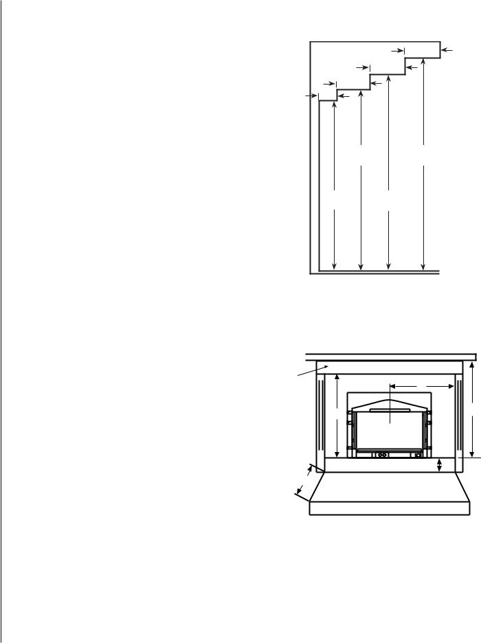
Clearances to Combustibles |
Facing and Mantel Clearances |
Minimum Clearances to Combustibles
E= 31-1/2" (800mm) from Top Facing to Bottom of Insert
F= 25-1/2” (648mm) from Center of Glass to Side Facing or Side Wall
J= 39” (991mm) from 10.5” (267mm) Mantel to Bottom of Insert
Hearth Protection
G = Minimum Hearth Protection from Front of Insert*
H = Vertical Distance from Insert Bottom to Combustible Material.
G |
13”(330mm) |
10”(254mm) |
0”(0mm) |
|
|
|
|
H |
0”(0mm) |
2”(21mm) |
4”(102mm) |
|
|
|
|
Note: Hearth protection to be min. 3/8” (10mm) thick noncombustible or equivalent, with a k factor of .84.
Insert Leveling
At each front and rear corner of the insert is an adjustable leg provided to level the insert should the hearth of the fireplace be uneven. To adjust the legs, loosen the two 5/32" allen head screws, move the leg to the desired height, and then tighten the screws. Repeat these steps for each adjusting leg.
|
3"/76mm |
3"/76mm |
|
3"/76mm |
Facing & |
1-1/2” |
|
38mm |
Mantel - |
|
Side View |
33-1/2” |
39-1/2” |
851mm |
1003mm |
31-1/2” |
36-1/2” |
800mm |
927mm |
Figure 4
Clearances
MantelANTEL 
RIM |
|
|
|
Trim |
|
|
F |
|
|
|
|
|
|
E |
J |
|
|
|
|
|
|
|
C |
|
|
|
L |
|
|
|
H |
|
G |
|
Hearth / Floor Protection |
|
|
|
|
Figure 5 |
|
|
|
NOTE: DIAGRAMS & ILLUSTRATIONS ARE NOT TO SCALE.
 Loading...