


Spectra i.Net®
Installation and Operations Manual

®
i.Net
installation & operations manual
table of contents
section 0 page 1
section 1
section 2
IMPORTANT SAFETY INSTRUCTIONS & PRECAUTIONS
INTRODUCTION - ABOUT SOUND MASKING
1.1 basic information on sound masking
i.Net® SYSTEM COMPONENTS DESCRIPTION page 5
2.1 system components
.01
.02
.03
.04
.05
.06
.07
.08
.09
.10
2.2 optional accessories
.11
.12
.13
.14
.15
.16
i.Lon
MPI
Jordna Hub
SmartSwitch
Power Supply
Operating Platform (OP)
IR Hub
Speakers
Router
FT-Terminator
RAMP
RIB Relay
Din Rail
Mic Pre-Amp
Paging Microphone
Wall Enclosure
page 2
page 3
page 8
section 3
section 4
SYSTEM FLOW & WIRE DIAGRAMS
3.1 system flow diagram page 10
3.2 system speaker placement and wire diagram page 11
CABLING
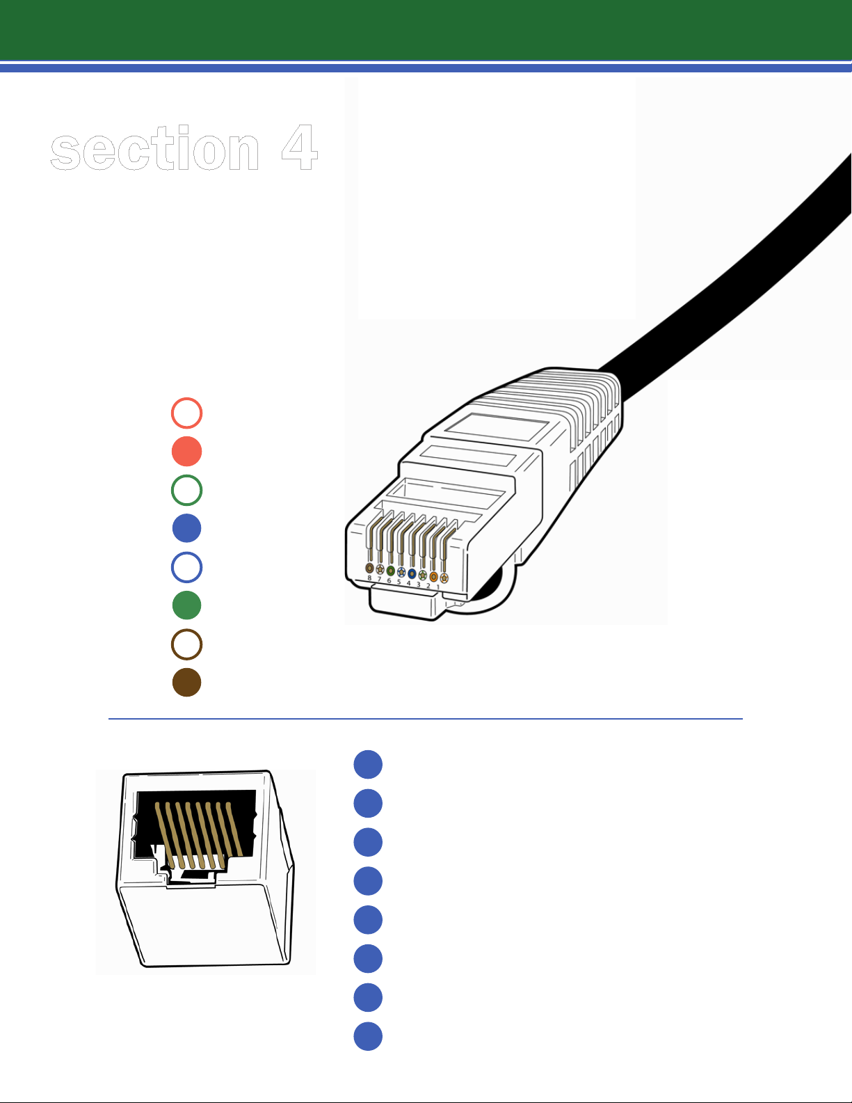
4.1 Speaker Cable
4.2 Data Cable
page 12
page 13

i.Net
®
installation & operations manual
table of contents
section 5
INSTALLATION (OP, SPEAKER, POWER SUPPLY)
5.1 step-by-step i.Net OP installation
5.2 i.Net OP and speaker placement
5.3 hang speakers/inline speaker setting
5.4 hang OPs
5.5 wiring the speakers and OPs
5.6 power supply
5.7 installing power supply for other OP's
5.8 proper wiring
5.9 schematics
5.10 router
5.11 schematic (i.Net using a router)
5.12 router settings
5.13 handheld remote
5.14 IR port
5.15 IR hub
5.16 data cables (at last OP)
5.17 wiring schematics
page 14
page 15
page 16
page 17
page 18
page 20
page 21
page 22
page 23
page 26
page 27
page 28
page 31
page 33
page 34
page 36
page 38
section 6
HEADEND EQUIPMENT INSTALLATION & POWERING
THE NETWORK
6.1
6.2
6.3
6.4
6.5
6.6
6.7
6.8
6.9
headend equipment installation
system connections
schematic (i.Lon close up)
dry contact mute & unmute
schematic (connecting the i.Lon, MPI & OP)
installing the MPI (optional)
connecting system to MPI
telephone hookup to MPI
ring down unit
page 39
page 39
page 40
page 41
page 42
page 43
page 44
page 45
page 46
page 47

section 7
i.Net
®
installation & operations manual
table of contents
7.1 manual system access & tuning
7.2 final wiring checklist
7.3 continuinty testing diagram
7.4 training program
7.5 online training reference
page 48
page 49
page 51
page 52
page 53
important
1
safety instructions
1
Follow all instructions.
Do not use this equipment near water.
2
3
Clean only with dry cloth.
Do not block any ventilation openings. Install in accordance with the
4
manufacturer’s instructions.
Do not install near any heat sources such as radiators, heat
5
registers, stoves, or other apparatus (including amplifiers) that
produce heat.
WARNING
To reduce the risk of re
or electric shock, do not
expose this equipment
to rain or moisture.
Equipment should not be
exposed to dripping or
splashing and no objects
lled with liquids should be
placed on the equipment.
6
7
8
9
10
Only use attachments/accessories specified by the manufacturer.
Protect your equipment with surge protector and UPS equipment.
Refer all servicing to qualified service personnel. Servicing is required
when the apparatus has been damaged in any way, such as if the
power-supply cord or plug is damaged; liquid has been spilled or objects
have fallen into the apparatus; the apparatus has been exposed to rain
or moisture; does not operate normally; or has been dropped.
Follow COMPLETE instructions for wiring the system and ALL system checks
before powering the system on for the first time, to avoid irreversible
damage to the components. Ensure proper polarity for wiring with regard to
power, data and audio output.
Do NOT plug any i.Net devices into a computer or network or like
equipment other than i.Net devices unless specifically asked to do so
in the installation manual.

i.Net
2
NOTE TO THE INSTALLATION TEAM
Welcome to Lencore’s Spectra i.Net® system, the intelligent sound masking network!
What makes this system intelligent is its intuitive technology and its infinite flexibility
®
introduction
on an
several million square feet, with its state-of-the-art, networked capabilities for sound
masking, music and paging.
The combined innovations of the complete sound masking system, sound sources,
speakers, power supply, i.Lon server, central online Sound Manager control and one-
touch remote control – put the Spectra i.Net® system on a new level of customization
and performance for sound quality, tuning flexibility, and more.
Like every Lencore Spectra® Sound Masking System, the Spectra i.Net® system achieves
uniform speech privacy throughout 100 percent of the space, plus sound comfort
(critical to ongoing use of any sound masking system).
INSTALLER BENEFITS
Installing a Spectra i.Net® masking system is faster and easier than any other sound
masking system, thanks to Lencore’s careful design of system components.
open-platform system. The system is suitable for any project size as large as
Standard RJ45 connectors are used throughout the system for connecting sound
masking speakers and OP to OP. This enables a plug and play installation and reduces
the need to strip and connect wires, saving installation time and ensuring a cleaner,
debris free installation. All wiring in the ceiling plenum is kept neat and organized with
modular connectors integrated into each speaker and OP.
Simplified connections add to the new system’s flexibility. Any changes or additions to
the network, such as channel, speaker or OP additions, layout modifications or zone
configurations can be made quickly.

section 1
3
1.1 | basic information on sound masking
You’re a Crucial Part of a Sound Decision
Working in an office environment poses a number of challenges to today’s workers;
among them, performing at high levels with more distractions than ever before to
contend with. You have been asked to play a part of the solution to two common and
often-neglected problems: privacy and noise.
Privacy and noise are big issues, especially in open office settings with a large number
of workstations or cubicles. And notably, in healthcare and related service fields,
protecting sensitive patient information is not just a top priority, it is the law.
The good news: utilizing a sound masking system is a cost effective solution. As
a qualified installer, you have become a crucial part of our client’s future
office environment. The equipment you are installing will play a vital role in not
only the privacy of our end user, but in their productivity and ability to concentrate
as well. A successful sound masking installation, in fact, should enable the people
who work in the environment to perform at their best.
You have been provided with state-of-the-art equipment and technology to install,
test, tune and finalize. As such, your goals for the completed installation should be:
1
Tuning the system to the proper dB level
2
Achieving proper sound uniformity
3
Managing expectations for the product
Sound masking involves much more than a series of speakers, switches and wiring
hidden somewhere above the ceiling. It has evolved into a science that literally affects
the way a workspace works.
Congratulations on being asked to perform a vital service for this client. You will leave
the workspace a better, more focused place to work. Those who will benefit from
your efforts will be better workers, and their companies more efficient, and you will
have made a contribution to their future success!
WHAT IS SOUND MASKING?
Sound masking is a means of adding background sound to a work environment to make
1
conversations more private (speech privacy) and to reduce extraneous conversations and
noise.
Masking systems have an integrated sound source, an amplifier, an equalizer, and
2
speakers that produce and carry an electronic sound that should be barely perceptible,
non-directional and harmoniously uniform throughout a given space.

section 1
4
1.1 | basic information on sound masking
You’re a Crucial Part of a Sound Decision
HOW DOES SOUND MASKING WORK?
Sound masking works because it changes the ‘dynamic range’ of sound in an
environment. Typically, the dynamic range in most environments is large, meaning
that there is a great degree of difference between the lowest, or ambient, sound level
and the highest levels of sound, when people are actively speaking and working.
Work environments are perceived as noisy precisely because of this large dynamic
range. The higher dB sound of normal speech is easily heard in a backdrop of a lower,
ambient background sound. Sound masking works by subtly raising the ambient
background sound level, thereby reducing sound’s dynamic range. This effectively
“masks” unwanted noise, makes speech unintelligible (creating privacy), and makes
the work environment acoustically comfortable.
WHAT ARE THE CRITERIA FOR PERFORMANCE?
The sound from a masking system must accomplish two things:
It must mask speech (providing measurable speech privacy)
1
It must not be a distraction (must be a “comfortable” sound)
2
GETTING A COMFORTABLE SOUND
How do you add sound with a masking system so that the system itself is not
distracting or annoying? The answer is by properly tuning the system to meet the
needs of the space. Lencore's system, when tuned properly, is very comfortable while
also creating speech privacy.
A sound masking system must be tuned so that the frequencies fall within the
preferred sound masking curve. The system should also utilize tight tolerances
for the decibel (dB) level within the space.
Spatial uniformity is also critical to a comfortable sound. Follow the tuning section
carefully and please call Lencore's main office if you have any questions.
section 2
5
2.1 | system components
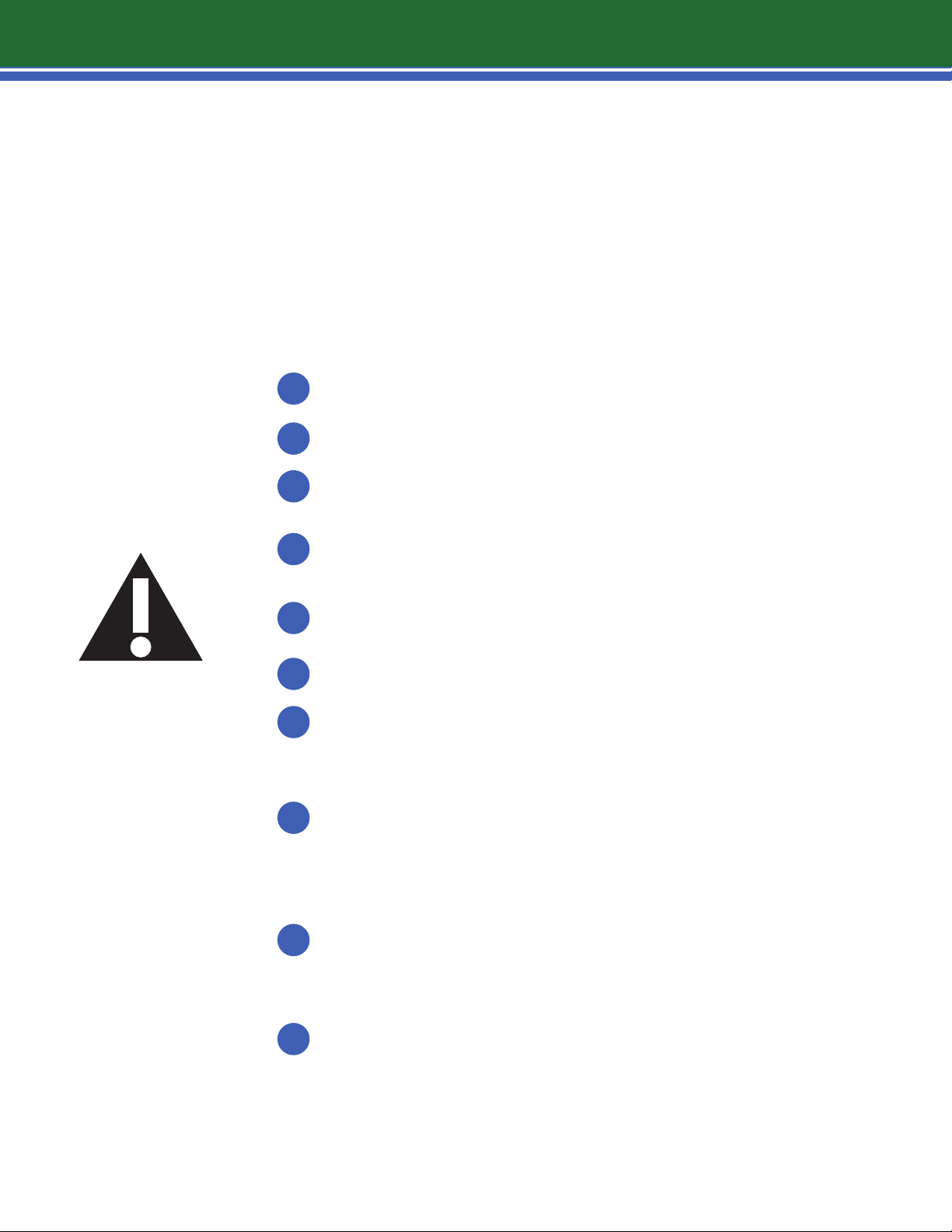
.01-i.LON SmartServer The Lencore System uses an i.LON®
SmartServer as its head-end equipment to control the networked
system. The i.LON® SmartServer oers exceptional features, solid
construction, and the flexibility to monitor and control the system
from virtually anywhere.
Link to Product Page
.02-MPI
Lencore’s Music Page Interface (MPI) replaces all the bulky head-end
equipment that that is associated with music and paging systems.
With the MPI, there is no need for additional cable home runs,
amplifiers, separate equalizers, special switching equipment or
matching vendors for compatible product interfaces. The MPI
allows for the addition of telephone and audio inputs.
Link to Product Page
.03-Jordna Hub The Jordna Hub provides the ability to split the
system’s signal and distribute it to multiple points. It provides
an input that connects to the i.Net Operating Platform (OP) and
has four outputs that enable the hub to branch to other i.Net OP
locations in separate buildings or facilities. When the need for
wider system coverage and signal distribution is required, Jordna
Hubs can be connected to each other, providing clients with
almost infinite scalability to meet future growth.
Link to Product Page
section 2
6
2.1 | system components
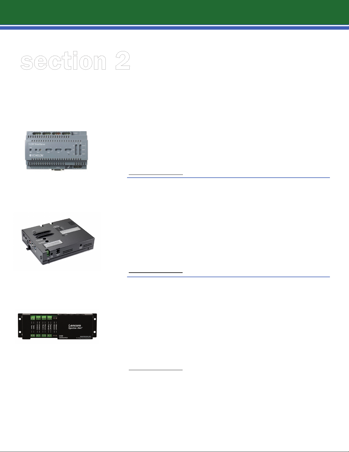
.04-SmartSwitch The Lencore SmartSwitch provides total data
and audio redundancy to any i.Net system. It reports and
monitors the integrity of the data and audio lines.
Link to Product Page
.05-Power Supply The Lencore System uses a 36 or 48 Volt DC
power supply unit to power the i.Net OP. The power supply is
connected to the sound source (OP) using 2 conductor, plenum rated
16 gauge wire.
Link to Product Page
.06-OP The heart of the Spectra® i.Net® is the OP (Operating
Platform), the primary sound source that produces, equalizes and
distributes the sound for masking, music and paging.
Link to Product Page
.07-IR HUB Each OP (sound source) of the Spectra i.Net® System has
an integrated IR Port. This port can be connected to the IR Hub and IR
Keypad to provide up to four individual audio channel controls per OP.
Using an IR Hub channel, one can make volume and contour control
adjustments for masking, paging and music, by pointing a remote
control at the IR Keypad.
Link to Product Page
section 2
7
2.1 | system components
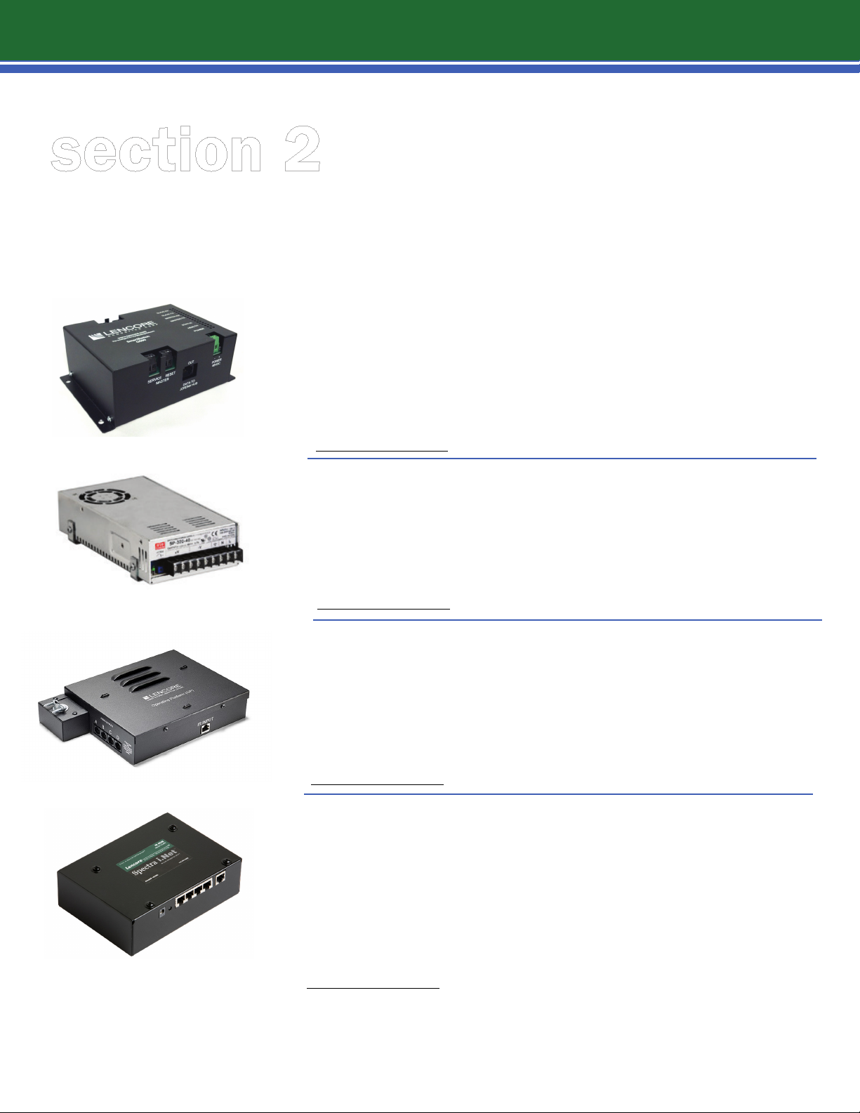
.08-Speakers The Spectra i.Net® speakers enable the masking to
be distributed uniformly throughout the space. Typically hung
above the ceiling tiles, the speakers fill the plenum with sound that
gently filters into the environment below to create speech privacy.
Spectra i.Net® speakers are perfectly matched for the OP to ensure
the highest quality of sound masking
Link to Product Page
.09-Router A router ensures quality data transmission, paging and
music integrity across long cable runs. Each router terminates and
rebroadcasts signals back to full strength allowing the system wiring
network to work at best practices standards.
Link to Product Page
.10-Data Terminator The Spectra i.Net® Data Terminator is used
at the last Operating Platform (OP) unit to end the OP data run and
paging and music channels. One terminator is used for each project
requiring a data, paging or music hook up.
Link to Product Page

section 2
8
2.2 | optional accessories
.11-RAMP (pre-recorded messages) Designed to address
paging and mass communication needs, the RAMP™ (Record, Audio,
MPEG Player) oers the necessary features for a variety of audio
announcement applications, ranging from public addresses to safety
announcements.
Link to Product Page
.12-Relay Used for triggering strobes, pre-recorded messages or
other devices.
Link to Product Page
.13-Din Rail This rail is used to attach the i.Lon server to the wall,
to equipment or in the enclosure. It is 8 inches long and slotted
galvanized steel.
section 2
9
2.2 | optional accessories
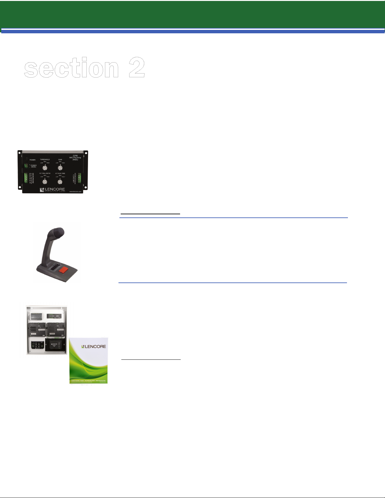
.14 Mic Pre-Amp Designed to offer superior paging, the Microphone
Pre-Amplifier with Automatic Gain Control (AGC) is Lencore’s next
generation in high performance technology. The Microphone PreAmplifier improves vocal clarity for paging and emergency messaging.
Each unit incorporates Automatic Gain Control to deliver greater
compression and feedback suppression.
Link to Product Page
.15 Paging Microphone A microphone input device is often used
to speed communication through push and talk. This device is easily
incorporated into the design of a mass notification system.
.16 Wall Enclosure For privacy, comfort, paging, audio and mass
notification, Lencore offers clients the Engineered System Solution
Enclosure. This packaged approach provides clients with an
enclosure that houses all of the system’s head-end equipment
completely pre-installed and wired.
Link to Product Page
section 3
10
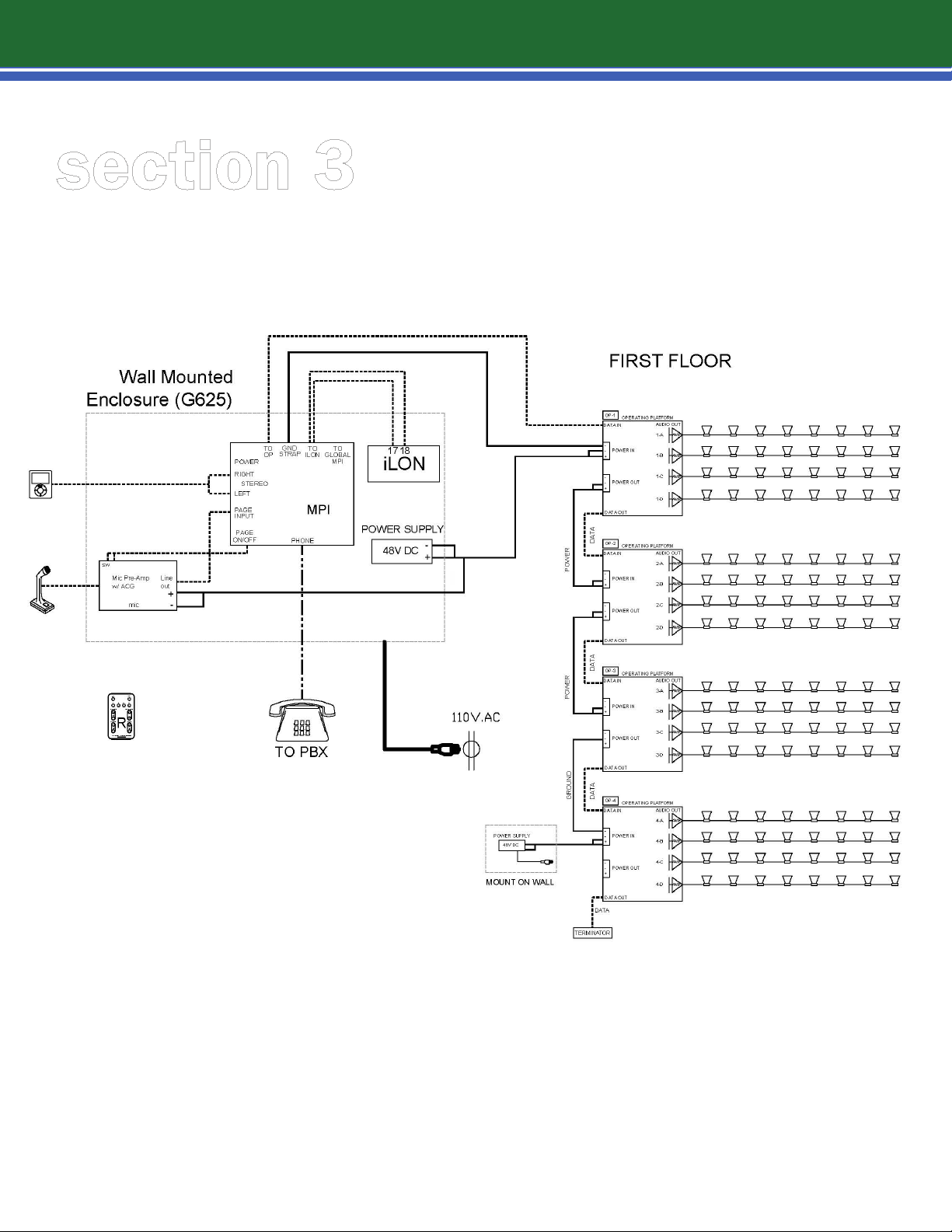
3.1 | Spectra i.Net ow diagram
Spectra i.Net
Following is an example of an i.Net layout. Each project is unique and you will need to reference the
project’s specific design flow and wire diagrams.
®
section 3
11
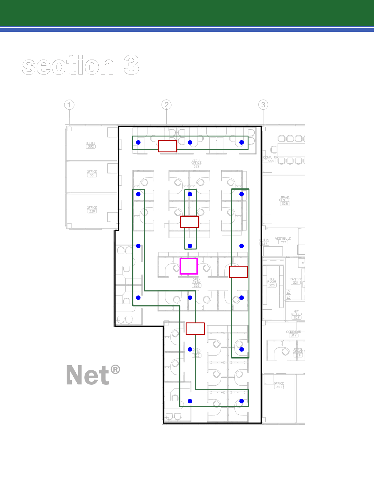
3.2 | system speaker placement and wire diagram
1-A
1-D
i.Net
®
OP
1
1-B
1-C
Following is an example of an i.Net layout. Each project is unique and you will need to reference the
project’s specific design flow and wire diagrams.
section 4
12
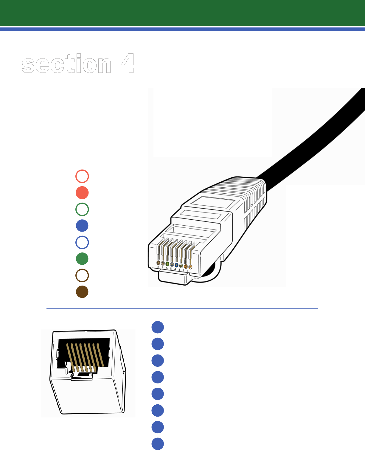
4.1 | speaker cable (RJ45) 568B
Speaker Cable connections are from i.Net OP to Speakers and from
Speaker to Speaker.
The pin out on the RJ45 is 568B.
The RJ45 connectors for the SPEAKER cables are non-shielded.
PINS - 568 B
ORANGE|WHITE
1
ORANGE
2
GREEN|WHITE
3
BLUE
4
BLUE|WHITE
5
6
GREEN
BROWN|WHITE
7
8
BROWN
1
2
3
4
5
6
7
AUDIO (+)
AUDIO (+)
AUDIO (+)
AUDIO (+)
AUDIO (-)
AUDIO (-)
AUDIO (-)
speaker
8
AUDIO (-)
section 4
13
4.2 | data cable (RJ45) 568B
Data Cable connections are from the Music Page Interface to i.Net OP
and from i.Net OP to i.Net OP.
The pin out on the RJ45 is 568B.
The RJ45 connectors for the DATA cables are non-shielded.
PINS - 568 B
ORANGE|WHITE
1
ORANGE
2
GREEN|WHITE
3
BLUE
4
BLUE|WHITE
5
6
GREEN
BROWN|WHITE
7
8
BROWN
LON A | ILON® DATA NETWORK
1
LON B | ILON® DATA NETWORK
2
INITIALIZATION (SEQUENCER)
3
PAGE (+)
4
PAGE (-)
5
INITIALIZATION (SEQUENCER)
6
MUSIC (+)
7
data
8
MUSIC (-)

section 5
14
5.1 | step-by-step i.Net OP installation instructions
PREPARATION
Review boxes. Refer to packing list and check equipment in boxes. Be certain you have:
1
a
All Operating Platforms – Please secure all OPs to a very safe place.
i.LON (make sure you secure the i.LON – approximate cost $2000.00).
b
c
The terminator(s). Keep these in a safe place.
d
Power supplies, MPI (headend enclosure).
e
Speaker boxes. Count all the items to ensure that you have all of your equipment.
Open speaker boxes to properly count the number of speakers you have.
2
Review Wiring and Installation Drawings:
a
Verify where wiring will be installed BEFORE placing equipment.
Check wiring runs to properly estimate needed quantity of wire for the project.
b
Check quantity for: Power Wire (16/2), Data Wire (CAT 5e, 4 pair), Speaker Wire
(CAT 5e, 4 pair). Check that all wiring is Plenum Rated, Only use Plenum Rated
wiring in Plenums.
Verify where OPs and speakers will be installed. Please note OPs need
c
to be installed in sequence.
Review location for placing the head end equipment (electrical or IT closet) – make
3
sure that you have access to power in the closet. Follow all safety precautions. Use a
UPS (uninterruptible power supply) for powering the head end for all emergency
paging systems. Check for and identify intended placement for the:
a
Wall mounted enclosure or rack mounted drawer
4
Identify any major site impediments such as:
a
Slab-to-slab wall
b
Shafts
c
Risers (wiring raceways from floor to floor
d
Obstructions in plenum
REMINDER
Secure all OPs, MPI AND
i.LON equipment on site.
Store securely & safely.
OPs, MPI AND i.LON are
expensive items!

section 5
15
5.2 | i.Net OP and speaker placement
Place the
1
approximate installation locations.
Place
2
Make sure the OPs are not put in harm’s way of people working or walking.
NEVER PLUG AN i.NET OP INTO ANY COMPUTER OR NETWORK EQUIPMENT
OTHER THAN AN i.LON OR ANOTHER OP.
NEVER INSTALL POWER WIRES WHILE THE POWER IS ON. IT IS DANGEROUS AND
WILL DAMAGE THE OPs, ONLY TURN THE POWER ON WHEN THE POWER WIRES ARE
FULLY AND PROPERLY WIRED AND INSTALLED.
INSTALLATION
IMPORTANT: Lencore suggests installing equipment in this sequence:
i.Net speakers by walking the floor and set the speakers on the floor at
OPs
on the floor at approximate locations (check drawing for correct sequence).
1
Hang speakers*
2
Hang OPs
3
Run wire with power OFF
ATTENTION: DO NOT HOOK UP POWER UNTIL THE SYSTEM IS FULLY
INSTALLED. POWER CONNECTIONS MUST BE DOUBLE-CHECKED TO
ENSURE PROPER POLARITY.
CRITICAL: CHECK WIRING POLARITY (+ AND -) BEFORE FIRING THE SYSTEM ON,
OTHERWISE, IRREVERSIBLE DAMAGE WILL OCCUR TO SOME OR ALL OF THE OPs.
* Speaker units will hang from the ceiling using the attached chain (supplied by Lencore).
Chain length should be cut to enable each speaker to hang a minimum of 6” above the ceiling
tile and a maximum of 12” above the ceiling tile, unless otherwise noted on the drawing.
NOTE: TO HELP MAINTAIN UNIFORMITY, KEEP THE CHAIN LENGTHS/HEIGHTS
CONSISTENT THROUGHOUT THE INSTALLATION AND SPACE.
HELPFUL HINT
It may be helpful to mark each speaker with a magic marker on the bottom for each OP, each
channel and speaker number, for example: OP #1, channel 1 - mark the speaker OP1A. Also when you
get to the end speaker on each channel, add “END” to this designation.

section 5
16
5.3 | hang speakers
1
Climb ladder and access the ceiling plenum
2
Hang speaker units in plenum area at marked locations using preferred hanging method
(powder action gun such as a Hilti-gun™ or drill and screw; check your local building codes
for allowable hanging methods and standards)
3
Drive a nail holding the clip with the speaker chain and speaker into ceiling
Pull and connect audio cables to speakers by channel
4
* keep speakers installed at very
consistent heights
6"-12"
NOTE: If installing inline speakers, make sure the potentiometer on the bottom of the speaker
is set to the MAXIMUM (clockwise) setting.
IMPORTANT
Follow channel designations
on drawings (1,2, 3,…8) so
that proper tuning of the system
can take place. Any changes
to the system MUST be
designated on the drawing

section 5
17
5.4 | hang i.Net operating platforms
You have received i.Net OPs pre-numbered – see label on each i.Net OP indicating its sequence
number. Check and install each respective i.Net OP according to the drawing.
i.Net OPs are hung from the ceiling using the attached chain (supplied by Lencore). Chain length
should be cut to enable each speaker to hang 6-12” above the ceiling tile or 3” below the
ceiling deck. Make sure air can circulate around the i.NetOP and that the i.Net OP is not
touching metal in the ceiling or plenum.
NOTE: Keep the chain lengths/heights consistent throughout the installation and space.
IMPORTANT: Lencore suggests installing equipment in this sequence:
Climb ladder and access the ceiling plenum
1
Hang i.Net OPs in plenum area at marked locations using preferred hanging
method (powder action gun such as a Hilti-gun™ or drill and screw; check
2
your local building codes for allowable hanging methods and standards)
3
Drive nail holding clip to i.Net OP chain and i.Net OP into ceiling
NOTE: Do not permit the i.Net OPs to touch any other metal in the ceiling. Isolate
each i.Net OP with wire ties.

section 5
18
5.5 | wiring the speakers and i.Net OPs
1
Power cables (16 gauge/2 conductor – Plenum Rated)
2
Data cables (CAT 5e or equivalent – 4 pair – Plenum Rated) – Straight Pin 568B Method
3
Speaker Cables (CAT 5e or equivalent – 4 pair – Plenum Rated) – Straight Pin 568B Method
PREPARATION
A
Check site drawing for wiring installation diagram
B
Use wiring diagram to determine approximate wiring lengths:
Approximately 15’ between speakers (Cat 5e 4 pair)
a
Approximately 3000’ total Data length
b
(AE Router needed at that point to extend distance)
IMPORTANT: Double-check for long home runs and runs between floors, as these
will require much longer lengths of wire. Check wiring schematics for your project.
C
For more detail about system wiring, see Section 4 – data cables
POWER CABLES
Power cables are plenum-rated, 16-gauge, two conductor cable
•
One power supply powers 3 i.Net OP's with paging and/or music (6 OP's masking only)
•
A common ground must exist
•
Between i.Net OP to i.Net OP
a
From the MPI located in the Lencore enclosure to the first i.Net
b
c
OP Between Floors
WARNING
NOTE: Do NOT activate power until the Power wires are checked for proper polarity and all
the i.Net OPs are wired for power in a power zone. DO NOT SKIP THIS STEP!!! If proper
polarity is NOT maintained, then irreversible damage to the OPs will occur.
DO NOT CONNECT OR DISCONNECT i.NET OPs WITH LIVE WIRE
as injury and shock may occur, and damage may be caused to the equipment.

section 5
19
5.5 | wiring the speakers and i.Net® ops
First, run power cables to the IN/OUT connections of each i.Net OP,
1
taking care to be consistent with positive and negative screw terminals.
Do NOT cross positive and negative connections while wiring power- irreversible
damage will occur.
Run the power cables (NOT LIVE) from the power supply unit in the electrical/ IT
2
closet to the power +/- screw terminal connections of the first i.Net OP.
Complete all other wiring (audio and data) and perform wiring checklist
3
BEFORE powering up the system.
WARNING
NOTE: Make sure that grounds are connected to grounds and positives
to positives, and that wires are not crossed anywhere in the entire system.
Double check the wiring at each power supply.
Follow all labeling for power.

section 5
20
5.6 | power supply
WHEN AN ADDITIONAL POWER SUPPLY NEEDS TO BE ADDED:
Typically, one power supply is needed for 3 i.Net OP's with paging and/or music (6, masking only).
WIRING BETWEEN POWER ZONES:
Add a ground wire between OPs (negative or conductor wire). DO
1
NOT CONNECT THE POSITIVE WIRE BETWEEN OPs.
Be sure ground cable is run between i.Net OPs.
Use the (-) Negative terminals IN and OUT appropriately.
NOTE

section 5
21
5.7 | installing power supply for other i.Net® ops
INSTALL THE POWER SUPPLY
Mount the power supply unit to the wall in a secure location as close to each i.Net OP as
1
possible. Use angle brackets and screws for mounting. Exception: 1st power supply in Lencore
branded enclosure for SmartSwitch and 1st i.Net OP.
2
Keep top fan and side vents exposed!
Take note of the three (3) positive and three (3) negative power terminals.
3
4
Do not plug in until system is completely wired and checked for polarity (see schematics on page 23).
WARNING
NOTE: DO NOT PLUG IN UNTIL SYSTEM IS COMPLETELY WIRED AND CHECKED FOR
POLARITY. Irreversible system damage will result if polarity is not kept.

section 5
22
5.8 | proper wiring
IMPORTANT! DAMAGE CAN OCCUR!
Check polarity of all wiring! If continuity is reversed with regard to the power CABLING (16
gauge, 2 conductor) at any point, some or all of the OPs will be irreversibly damaged.
MAKE SURE THAT between power zones a ground wire is ONLY installed connecting the
separate power zones/supplies.
MAKE SURE THAT YOU have connected to each Power Supply the correct wire to the low
voltage side AND that each wire is correctly connected to the appropriate and proper + and -.
VISUALLY INSPECT AND DO NOT LEAVE TO CHANCE!
MAKE SURE ALL OPS ARE WIRED CORRECTLY
AND FOLLOW CONTINUITY THROUGHOUT
THE ENTIRE SYSTEM (+ AND –).
You may turn on each power supply in sequence.
Visually inspect to insure that the i.Lon® server and MPI (if one is purchased for the project)
are properly wired and installed.
ONCE YOU HAVE VISUALLY INSPECTED EACH ITEM AND ESTABLISHED
CONFIDENCE THAT THERE IS CORRECT CONTINUITY THROUGHOUT THE POWER
WIRING, YOU MAY PROCEED TO THE NEXT STEP!

23
section 5
5.9 | schematics
SPECTRA I.NET® SOUND MASKING
SEPARATE POWER SUPPLIES WITH COMMON GROUND BETWEEN ZONES

section 5
24
5.9 | schematics
TO POWER THE SYSTEM:
Connect each power supply and i.Lon Central Control Server and MPI to a dedicated 20
1
amp receptacle. Each dedicated circuit must be a 120V/20 amp.
Once each item is connected, you may visually observe in the power supply a lit green
LED, and sequencing of lights on the i.Lon® server and MPI.
The i.Lon® needs approximately two minutes to completely boot up.
ONCE THE SYSTEM IS PLUGGED IN:
2
You will not hear any sound for approximately 30 seconds. The OPs count down from 20
to 0 before booting up. (This permits new software/firmware uploads and tracking of
any corrupt data.)

section 5
25
5.9 | schematics
Spectra i.Net Sound Masking
OP Wiring for Power
Spectra i.Net Sound Masking
wer Supply Wiring
Po

section 5
26
section 5
5.10 | router
At every 30th OP a router is typically needed, for example a router
is used between the 30th and 31st OP to insure consistent data
transmissions.
Connecting from the OUT data port of the 30th OP, connect
the data cable to the router.
Exit the router by the data out and connect to the next OP (31st)
via the OP’s data in using an integrated RJ45 connector.
NEVER PLUG A SPECTRA
i.NET ROUTER INTO ANY
COMPUTER OR NETWORK
OR LIKE DEVICE OTHER THAN A
SPECTRA i.NET EQUIPMENT.
DAMAGE TO COMPUTER OR LIKE
EQUIPMENT COULD OCCUR.
DATA IN
DATA IN SIDE DATA OUT SIDE
DATA OUT

section 5
27
section 5
5.11 | schematic
Spectra i.Net® Sound
Masking Using a Router

section 5section 5
28
5.12 | router settings
Lencore Router Jumper Description
J1 No settings required
J2 24VAC or DC, 300 mA
J3 Cat5e
J4 Cat5e
J5 Jumper in pin-1, pin-2, default
J6 Jumper in pin-1, pin-2, default
J7 See description below, all jumpers out default
J8 See description below
J9 See description below
J10 24VAC or DC, 300 mA (parallel with J2)
J11 Jumper in pin-2, pin-3, default
J12
In almost all installtion scenarios, J5 and J6 are terminated in their default position.
An exception might be in an external termination is used for some reason.
Scenario 1: Sound masking only or page / music volume and EQ adjusted by OP’s
(i.e. No external amplifier or external EQ)
J7 Jumper in pin-1, pin-2
Echelon router board
Power Jack
Data cable input
Data cable input
Network input terminator
Network output terminator
Page / Music Bypass
Page / Music screw terminal in
Page / Music screw terminal out
Power screw terminal
Page termination
Music termination Jumper in pin-2, pin-3, default
Jumper in pin-3, pin-4
Jumper in pin-5, pin-6
Jumper in pin-7, pin-8
Jumper in pin-9, pin-10
Data cable input
Data cable output
Ground2, Ground1 bypass, connects both grounds
Music - bypass, connects music - in to music - out
Music + bypass, connects music + in to music + out
Page - bypass, connects page - in to page - out
Page + bypass, connects page + in to page - out
J8 1-4 Nothing connected RJ45 J3 handles the page / music lines
5 - Ground Connect to (-) power of last OP’s (i.e OP30)
J9 1-4 Nothing connected
5 - Ground
J11 Jumper in pin-2, pin-3 Leaves page line unterminated
J12 Jumper in pin-2, pin-3 Leaves page line unterminated
RJ43 J4 handles the page / music lines
Connect to (-) power of first of additional OP’s (i.e OP31)
Last OP will have the external termination
Last OP will have the external termination

section 5section 5
29
5.12 | router settings
Lencore Router Jumper Description
Scenario 2:
J7 Jumper in pin-1, pin-2 Ground2, Ground1 connected, recommended
J8 1- Page+
J9 1- Page+
If an amplifier(s), such a two TOA BG1015’s are used, with high impedance balanced inputs, then...
Sound masking page and music
Audio volume and EQ adjusted by an external amplifier and / or EQ
Jumper in pin-3, only Music - in isolated from music - out
Jumper in pin-5, only Music + in isolated from music+ out
Jumper in pin-7, only Page - in isolated from page - out
Jumper in pin-9, only Page + in isolated from page 1 out
Connect to balanced + input of amplifier/EQ (ie. left channel +)
2 - Page 3 - Music +
4 - Music 5 - Ground
2 - Page 3 - Music +
4 - Music 5 - Ground
Connect to balanced - input of amplifier/EQ (i.e. left channel -)
Connect to balanced - input of amplifier/EQ (i.e. right channel+)
Connect to balanced - input of amplifier/EQ (i.e. right channel -)
Connect to (-) power of last OP (i.e. OP30)
Connect to balanced + output of amplifier/EQ (i.e. left channel +)
Connect to balanced - output of amplifier/EQ (i.e. left channel -)
Connect to balanced + output of amplifier/EQ (i.e. right channel+)
Connect to balanced - output of amplifier/EQ (i.e. right channel -)
Connect to (-) power of first of additional OP’s (i.e. OP31)
J11 Jumper in pin-1, pin-2
J12 Jumper in pin-1, pin-2
If another amplifier(s), or EQ that has 600 ohm low impedance balanced inputs then...
J11 Jumper in pin-2, pin-3 Leaves page line unterminated
J12 Jumper in pin-2, pin-3 Leaves page line unterminated
You must open the router housing to adjust any jumper settings. To open the router, unscrew all three outside
green screw terminals and pull terminals o the router housing (power, jumper in and jumper out).
Then unscrew one side and slide o housing top.
Then slide PC board out of housing (make sure you are personally discharged of any and all static electricity
before handling a raw PC board).
Make necessary jumper changes or modications.
Put unit back together.
The Amplifier will provide the page termination
The Amplifier will provide the music termination

30
section 5section 5
5.12 | router settings
Router PC board showing
jumpers (J1 - J12)

section 5section 5
31
5.13 | handheld remote
USING THE HAND HELD REMOTE:
Each OP is equipped with an integrated infrared eye on the bottom of the OP enclosure allowing
remote usage and connectivity. Using the Spectra i.Net® hand-held remote control point the remote
to the bottom of the OP enclosure for IR line of sight control. Adjustments to the OP may be made
from the remote control for masking volume and masking contour or paging volume or music
volume by either single audio channel or entire OP.

section 5
32
section 5
5.13 | using the handheld remote
You will also notice that the green LED light will stay lit while the remote is depressed, visually cueing
that the remote is working and the OP is responding to the remote’s signals.
When you are satisfied that the space has been tuned to the proper dBA level and has achieved
proper sound uniformity, you can close up the remaining ceiling tiles to complete the project.
Remove any debris created on site and contact your project team leader or Lencore to let them
know the work had been completed.
Tuning the sound masking correctly is extremely important. The measure of the projects success will
be measured by the quality of the sound. Ensure that the correct and appropriate amount of time is
spent tuning and fine tuning the entire project.
USING THE HAND HELD REMOTE CONTROL:

section 5
33
section 5
5.14 | IR port
TO HOOKUP AN ON WALL REMOTE USING THE OP IR PORT...
The on-wall IR Keypad
uses CAT 5e wire with a
terminated RJ45 @ the
end of the wire that is
installed at the OP
Insert the RJ45
into the IR port
located on the OP.
Wall Keypad

section 5
34
section 5
5.15 | IR Hub
Each OP is equipped with an integrated infrared eye on the bottom of the OP enclosure
allowing remote usage and connectivity. Using the Spectra i.Net hand-held remote control, point
the remote to the bottom of the OP enclosure for IR line of sight control. Adjustments to the OP may
be made from the remote control for masking volume and masking contour or paging volume or
music volume by either single audio channel or entire OP.
Each OP is also equipped with an IR port on the side of the OP enclosure. This port allows an IR
keypad to be installed via plenum rated CAT 5e wire and an RJ45 connector from the OP located in
the ceiling plenum to the space below the plenum, in a location along a wall, similar to that of a
normal wall switch. This setup allows for IR keypad use without having to remove a ceiling tile.
The IR Hub is an additional component that allows for more than one keypad to be installed in an OP
IR port giving a single OP audio channel specific control to a respective keypad. Up to four keypads
may be installed in each hub allowing four keypads to be installed per each OP.

section 5
35
section 5
5.15 | IR Hub
IR HUB – CONNECTING TO MORE THAN ONE IR KEYPAD.
When installing more than one IR Keypad to an OP, use the IR Hub as shown below.
power supply
hooks into
power input.
IR Keypad
*See data sheet for IR Keypad configuration*
IR Keypad Data Sheet

section 5
36
5.16 | data cables
1
At the last i.Net OP:
Run the last data cable to the IN jack of the last i.Net OP in
a
the project.
b
In the last i.Net OP, click the data terminator into the data
OUT jack. This should only be installed in the last i.Net OP.
c
In the last i.Net OP, run a cable from the data OUT to the head end
equipment in the data closet. This will connect to the data IN from
the last i.Net OP on the SmartSwitch.

section 5
37
5.16 | data cables
The terminator enables the networked system to identify the last OP as the
final data recipient in the chain, and thus terminate the message relay.

section 5
38
5.17 | wiring schematics

section 6
39
6.1 | head end equipment installation
HEAD END EQUIPMENT LIST:
i.LON®
•
Music and Paging Interface (optional)
•
SmartSwitch (optional)
•
Jordna Hub
•
FT Terminator (optional)
•
Mic Pre-Amp (Optional equipment)
•
320 watt, 48V Power supply
•
For SmartSwitch and first i.Net OP
•
For Mic Pre-Amp (optional)
•
1
Electrical Requirements:
a
One dedicated 120v/20 Amp circuit is suggested for the Lencore branded enclosure
Installing Head End Equipment (Din Rail and i.LON) (This may already be pre-wired)
2
WARNING
NOTE: Never use a ground lifter. Always use a proper three prong adapter for safety.

section 6
40
6.2 | system connections
Connect the Data CAT5e RJ45 cable that is going to the first i.Net OP to
1
the connection marked “TO OP” on the MPI.
You must also connect a ground wire from the MPI to the first i.Net OP. Doing this
2
connects the MPI ground to the i.Net OP ground. (Negative terminal on i.Net OP). All
wiring from the MPI must go to the SAME OP and must remain consistent.
See the MPI label to verify which audio or paging input you may need and to connect
3
appropriate music source or phone page into the MPI.

section 6
®
41
6.3 | schematics
SPECTRA I.NET SOUND MASKING
I.LON 100® CLOSE UPS
Conductor Wire. 16
gauge, goes from
i.LON #17 & #18 to
either MPI or if no
MPI exists, to a
Jordna Hub on the
black screw
terminals labeled
data.

section 6
®
Sound Masking
42
6.4 | dry contact- mute & unmute schematic
Top View
Connect to dr
contacts to mute and
unmute masking.
+
-
umper
J
wire from
y
Pin #16 to Pin #20
The i.Lon® oers the ability to quickly mute and unmute the sound masking for
the entire system via inputs #15 & # 19.
Connect a jumper wire from Pin #16 to Pin #20.
Connect the digital input to a set of dry contacts to mute and unmute.
*Closed contact = Mute

section 6
®
43
6.5 | connecting the i.Lon, MPI and OP schematic

section 6
44
6.6 | installing the MPI (optional)
The Music and Paging Interface (MPI)
The MPI is an optional system component. It sequences the OPs and has inputs for:
The i.Lon® network hub
Music
Paging
FOLLOW THESE STEPS TO INSTALL THE MPI:
1
Mount the MPI to the wall
Connect the MPI to the i.Lon® using two conductor/one pair wire (16 gauge).
2
Connect each wire to the screw terminal on bottom of MPI to the i.Lon®.
I.LON CONNECTIONS
One wire to #17 (LON® B/PLT-)
One wire to #18 (LON® A/PLT+)
When installing the i.Lon®’s data connection to the MPI, polarity is unimportant, however,
make sure the two wires at the screw terminals are clean and not touching or crossed.
Coming out from the MPI, use a data cable, 4-pair CAT 5E with an RJ45 connector.
3
Plug into the 10/100 Ethernet base connection from the MPI to the data IN port of
the first OP.
You must also connect a ground wire from the MPI to the OP that Connects the MPI
ground to the OP ground.
See the MPI label to verify which audio or paging input you may need and to connect
appropriate music source or phone page into the MPI.

section 6
Connecting System to MPI – See larger diagram on page 49
45
6.7 | connecting system to MPI

section 6
46
6.8 | telephone hookup to MPI
A POTS LINE IS A 2 WIRE ANALOG APPEARANCE THAT USUALLY
ORIGINATES AT A TELEPHONE COMPANY CENTRAL OFFICE.
1
It is a 2 wire (Tip and Ring) analog appearance.
2
It is configured to be a loop start.
3
Battery voltage is 48 Volts.
4
Loop current must be 23 milli amps.
Must have DTMF signaling capability.
5
6
Must have hang-up (winking) supervision capability.

section 6
47
6.9 | ring down unit
RING DOWN UNIT
A ring-down unit is used to connect a telephone trunk line
or unpowered analog telephone to the MPI for telephone paging.
The ring-down unit acts as central telephone office (co).
RING-DOWN UNIT SETTINGS
VIKING© MODEL DLE-300
Installation of the Viking© Model DLE-300 advanced line simulator
with Lencore’s Spectra i.Net® MPI board.
FRONT PANEL DIP SWITCHES
1 down
2 down
3 down
4 down
5 down
6 up
7 up
8 down
INTERNAL JUMPERS
JP1 installed
JP2 installed
JP3 installed
JP4 installed
JP5 uninstalled
JP6 installed
Remove internal jumper from JP5 and move it to JP6.
All other internal jumpers leave as is.
TELEPHONE PATCH CORD
Use a t
elephone patch cord to connect DEV-2 RJ11 to MPI RJ11 connector.
Use another telephone patch cord to connect DEV-1 to a single line telephone.
or
USER TELEPHONE SYSTEM
PBX--------\
Trunk Port1-----> to DEV-1 RJ11

section 7
48
7.1 | manual system access & tuning
Spectra i.Net® System will automatically default to the acoustical
A
handbook’s preferred curve.
Using a quality sound level meter to check the setting:
B
Set the entire environment at 47.5 dBA as measured four feet above the finished
•
floor. You can make adjustments using the Sound Manager or hand-held remote.
NOTE This measurement should be accomplished in the
evening or after normal working hours and the ceiling tiles
should be 90-95 percent installed for an accurate reading.
For fine tuning
C
Leave all of the ceiling tiles that have an OP hanging above them exposed so that
•
incremental adjustments can be made with the hand-held remote control prior to
closing up the ceiling.
Use the hand-held infrared remote to make immediate adjustments to the volume
D
and contour of each channel (A,B,C, and D) at each OP. You may press the ALL button
on the remote to tune an entire OP if all of the speaker channels are in “like space.”
Aim the infrared remote control at the OP and press either the ALL button
(All Channels), or an individual channel, A,B,C, or D.
The LCD display will read the following for each:
Button on Remote = LCD Display
All = AL
A=A
B= b
C=C
D=d

section 7
49
7.2 | final wiring checklist
FINAL WIRING CHECKLIST BEFORE POWERING UP SYSTEM
Have you checked all home runs?
1
Have you checked all wiring between floors (risers)?
2
Are you sure all grounds are properly tied between i.Net OPs?
3
Have you made sure all Data and Speaker wires are tested and installed?
4
Check polarity of all wiring throughout, especially power cables. If continuity is
5
reversed at any point, some or all of the i.Net OPs will be irreversibly damaged.
NEVER WORK WITH POWER WIRE, OR CONNECT POWER WIRES TO
I.NET OPs, WHILE POWER IS ON.
TIP
TIP! Check data wires
by going to the Sound
Manager Congurator and
refreshing i.Net OPs after
each i.Net OP
is connected. This will
help to eliminate large
trouble shooting issues
at the end of the job.
WARNING
NEVER WIRE or CONNECT
POWER TO AN i.Net OP WHILE
POWER IS ON!!! i.Net OP will
lose its number identity.
Always connect wire to i.Net
OP while power supply is
not plugged in.

section 7
50
7.2 | nal wiring checklist
BEFORE POWERING UP SYSTEM
Have you checked all home runs? q YES
Have you checked all wiring between floors (risers)? q YES
Are you sure all grounds are properly tied between power zones? q YES
Have you made sure all Data and Audio wires are tested? q YES
Check polarity of all wiring throughout, especially power cables.
If continuity is reversed at any point, some or all of the OPs
will be irreversibly damaged.
WARNING NEVER WORK WITH WIRE, or connect wires to OP’s,
while POWER IS ON.
TIP Check data wires by going to the i.Lon® and refreshing OP’s after
each OP is connected. This will help to eliminate large trouble shooting
issues at the end of the job.
TIP Check all speaker wires and speakers for good integrity, simply unplug the
1st speaker wire from the OP and connect an RJ45 to a 8 conductor CAT5e wire on
one end and twist wire/pins 1,2 & 3 together and 4,5 & 6 together. This will give
you two leads + & -. Attach an OHM meter to the wire with the leads and attach
the other end into the first or last speaker in a run of speakers. If all is connected
correctly, you will approximate the following correct results on your OHM meter:
# of SPEAKERS OHMs*
For complete description, go to Spectra
i.Net® Continuity Testing Diagram on the
next page.
*Values are approx. based on 25’ cable run from OP to speaker and speaker to speaker.
1 32.4
2 16.5
3 11.3
4 8.8
5 7.3
6 6.4
7 5.8
8 5.3

section 7
(Figure 8)
®
51
7.3 | Spectra i.Net® continuity testing diagram
Operating Platform

section 7
52
7.4 | training program options
Lencore offers extended technical training on Spectra Classic, Spectra i.Net and n.FORM.
Training is conducted by a technical engineer in order to provide certification of the
Lencore systems. The day and a half program delivers the following:
Head End Equipment (Lencore’s Branded Enclosure)
•
Review of component functionality and need
•
Hands on installation training
•
Tuning and Balancing for sound masking systems
•
Software training for networked systems
•
Closeout documentation, creating proper as-builts
•
Troubleshooting and frequently-asked-questions
•
A certified installer should walk away from the training program with the following:
A Clear understanding of the Lencore systems and functionality
•
Installation expertise on Lencore’s systems
•
Ability to tune and balance a system post-installation
•
Network control expertise
•
System reporting capabilities
•
A certificate of training completion
•
Lencore offers the certification training free of charge to Lencore product installers.

section 7
53
7.5 | online training reference
Lencore also offers installation videos at www.Lencore.com. Visit our Resource Center or scan the
QR code below. Please feel free to use these reference sources for help with installation of:
Overview of each system and general applications
•
i.Net Operating Platform
•
i.Net Speakers
•
Ceiling Plate Speakers
•
Cable Trouble Shooting
•
*For further technical support, please email: support@lencore.com
LINK TO LENCORE VIDEOS

LENCORE ACOUSTICS CORP.
1 Crossways Park Drive West Woodbury, NY 11797
516-682-9292
info@lencore.com www.lencore.com
The information contained herein is proprietary to Lencore Acoustics Corp. and copyright protected.
No part of this manual can be copied, used or distributed without prior authorization from Lencore Acoustics
Corp. © Copyright 2014 REV 5002-14-10
 Loading...