

Lencore LP-2 Installation & Programming Manual
INSTALLATION &
PROGRAMMING
MANUAL
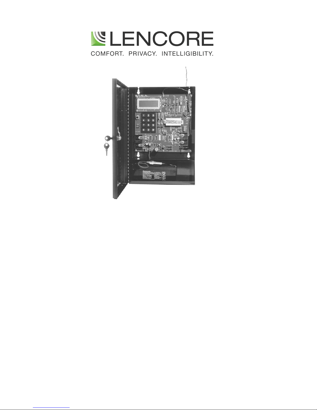
PROGRAMMABLE TIMER
(MODEL LP-2)

Copyright © Lencore Acoustics Corp.
All rights reserved.
April 2000
CCOONNTTEENNTTSS
Introduction 3
Display 3
Keyboard 4
Installation 4
Set Up 4
Connecting the blue and black zone wires 4
Connecting the wall transformer 4
Connecting the battery 4
Battery Switch (S1) & Test/Normal Switch 5
Zone slide controls 5
Programming 6
Setting date and year 6
Setting time of day 6
Daylight savings 6
Look at masking attenuation levels 6
Change masking attenuation levels 6
Look at minutes per dB 7
Change minutes per dB 7
Copy day of week to next day 7
Copy Zone 1 to Zone 2 (entire week) 8
Look at acclimate status 8
Turn on/off acclimate 8
Change acclimate dB's / days per dB 8
Acclimate help screen 9
Minutes per dB help screen 9
Leap years 10
Daylight savings occurrences 10
Reset button 10
Initial default values 10
Default attenuation values after a reset 10
Default minutes per dB values after a reset 11
Other default values after a reset 12
Specifications 12
Timer record sheets 13/14
-2-

Notes 15
Menu flow chart 16
INTRODUCTION
The Lencore Model LP-2 Programmable Timer is a two zone electronic attenuator
when attached to the blue and black wires of model LM-6 master sound masking
units. R aisin g o f ma skin g l evel s is s imul ate d o nly . Th at is , t he high es t le vel o f s oun d
masking is the same as if the timer were not attached to the blue and black wires
of the masters.
There are three separate areas of attenuation. Each hour of the 24 hours in a day
has a programmed attenuation value in the range of 0 dB to -9 dB inclusiv e. The
zone slide controls have an attenuation range of -5 dB to +5 dB inclusive. Finally the
acclimation setting has a programmed attenuation range of -1 dB to -9 dB
inclusive. If acclimation is turned off or has timed out, attenuation is 0 dB.
The total attenuation that is displayed, and output to each zone, is the sum of the
dB setting for the current hour of the day**, plus the zone slide control dB setting,
plus the acclimation db setting. Note that the maximum total attenuation possible
is -18 dB even if the programming gives a result beyond this.
** Please tak e into account the minutes p er dB setting for this parti cular hour
to determine at what minute final attenuation is reached. This applies only if
the previous hour setting is different from the current hour.
The two zones can be programmed independently except the acclimation dB's
that are common to both. Each day of the week can be programmed differently
also. For example Saturday and Sunday can be programmed different from Friday.
From the menu driven screens on the display you can select the zone, the day, the
hour and enter the amount of attenuation desired. Often the default attenuation
settings are adequate for most office situations and no programming is necessary.
There are approximately 35 different screens or menus that can be displayed. You
can follow the flow of these screens in the menu flow chart provided. Once finished
you should always return to the main screen, the one that shows the date, time and
zone dB values.
DISPLAY
The liquid crystal display (LCD) has 4 lines of 20 characters each. In the main screen
line 1 shows the date. Line 2 shows the day of week, time of day, the letter A for
A.M. or P for P.M.
-3-

On line 3, Z1 refers to Zone 1, Z2 refers to Zone 2. The current values in dB's are
shown for each zone. These values are referenced to an office masking level of 47
dB. That is, a reading of "Z1=0dB" and "Z2=0dB" on the timer display, means an office
masking level of 47 db for both zones. This reading assumes that all the LM-6 master
units have been adjusted as per the installation section in this manual. For example,
a reading of "Z1=+2dB" and "Z2=-2dB" on the timer display means an office masking
level of 49 dB for Zone 1 and 45 dB for Zone 2.
Line 4 usually displays a prompt line. It shows what keys should be pressed to
perform a certain task. In the date and time screen, which is the main screen, it will
display "Press 0 for Menu". After pressing 0 on the keyboard the display will change
and will prompt you with further choices.
KEYBOARD
The keyboard is similar to that used on a touch-tone telephone. The "#" key can
often be used to advance without changing a value (i.e., keep the current value).
The "*" key when pressed will exit some menus immediately. However, it is not a
cancel key. Any changes made before pressing the "*" key will be kept.
INSTALLATION
SET UP
We suggest you hang the timer panel box prior to activating the Programmable
Timer.
Mount the timer enclosure securely on a wall at eye level near a 120 volt A.C.
socket. Open enclosure door and remove the keys taped to the inside left panel.
Use these keys to lock the timer box once all settings have been adjusted.
Now note the locations of Zone 1 output, Zone 2 output, 24-volt AC input and
battery fuse holder. The following steps, in the order given, are recommended for a
two-zone hookup.
1. Bring the blue and black wires from Zone 1 through the hole in the enclosure.
Strip ¼ inch of insulation from both wires. Insert the black wire into P.C. Board
terminal marked Com1. Insert the blue wire into P.C. Board terminal marked
Zone1. Tighten the screws on the terminal so the wires are secured.
2. Bring the blue and black wires from Zone 2 through the hole in the enclosure.
Strip ¼ inch of insulation from both wires. Insert the black wire into P.C. Board
terminal marked Com2. Insert the blue wire into P.C. Board terminal marked
Zone2. Tighten the screws on the terminal so the wires are secured.
Never connect the blue wires from Zone 1 to Zone 2 together. This includes the "home runs".
-4-

The two zon es mus t remain separ ate. If the re is on ly one zo ne to con nect to th e timer, l eave
Zone 2 unconnected. This is very important.
3. a) A 5-foot green wire is provided to attach the Timer Box to an earth
ground. Bring
this wire through the hole in the enclosure, strip ¼ inch of insulation and
attach to
a convenient earth ground.
b) Remove the 24-volt wall transformer from the bottom right section of the
panel box and feed the cable through the hole located at the top of the
panel box. Insert the miniature plug at the end of the cable to the
matching power jack marked J101 located at the bottom right of the PC
board.
4. Note the fuse holder and cables from the battery. Check that they are
properly attached and not touching the enclosure or P.C. Board. A spare
fuse is provided with the keys taped to the insi de left panel. Plug the wall
transformer into a 120-volt AC outlet. You should hear some beeps and the
display should come on.
5. Locate the battery switch labeled S1 on the lower left side of the P.C. board.
The Timer is shipped from the factory with this swi tch in the OFF position.
Switch it to the ON position. This will connect the battery to the P.C. board
and provide a back up in case of a power loss.
6. Enter the correct date and time using the keyboard.
To enter correct date:
Press 0 (for the menu screen)
Press 1
Enter month (two digits)
Enter day (two digits)
Enter year (four digits)
Press 0
To enter correct time:
Press 0 (for the menu screen)
Press 2
Press 1
Enter hour (two digits)
Enter minute (two digits)
Enter seconds (two digits)
Enter 0 for A.M. or 1 for P.M.
Press 0
Press 0
Check if the date and time is correct. If not, repeat the above
-5-

steps.
7. Locate the Test/Normal switch on the P.C. Board. Put the switch in Test
position. The display will change showing both a dB level and a voltage level
for each zone. This bypasses any programmed attenuation and allows for a
total system calibration of the LM-6 master units. Adjust the Zone 1 slide
control for a stable reading of 0 dB. Do the same for Zone 2.
8. The dB levels present here represent the change in decibels from 47dB. You
can either raise or lower the dB level (from this 47dB) here. With the
Test/Normal switch in Test posi tion, adjust all the LM-6 master units for an
office sound level reading of 47 dB's. When all the masters have been
adjusted and tuned as necessary, put the Test/Normal switch in Normal
position. The display will change to the date and time screen. The dB
readings may change as any programmed attenuation is taken into
account.
9. Program the timer as per customer specifications. Refer to the programming
section of this manual.
PROGRAMMING
The following keyboard key combinations are documented in a way that assumes
you are starting from the main screen. There will be situations where it is much
quicker to go from one sub-menu to another without returning to and starting from
the main screen. You may use these quicker routes at any time. However, for the
purpose of documentation, the main screen will be the starting point.
Date
Press 0 (for the menu screen)
Press 1
Enter month (two digits)
Enter day (two digits)
Enter year (four digits)
Press 0
Time
Press 0 (for the menu screen)
Press 2
Press 1
Enter hour (two digits)
Enter minute (two digits)
Enter seconds (two digits)
Enter 0 for A.M. or 1 for P.M.
-6-
 Loading...