

Page 1
Leica TCS SP5
User Manual
Page 2

Leica Microsystems CMS GmbH
Am Friedensplatz 3
68165 Mannheim
Germany
Telefon: +49 621 7028 0
Fax: +49 621 7028 2980
E-Mail: CLSM.support@leica-microsystems.com
Page 3

1 Notes about this manual page 1.............
1.1 Copyright page 1..............................................
2 General page 3...........................
2.1 About these operating instructions page 3.........................
3 Proper intended use page 5.................
4 Legal Notes page 7........................
4.1 DISCLOSURE page 7..........................................
4.2 REVISIONS AND CHANGES page 8.............................
4.3 WARRANTY page 8............................................
4.4 Patents page 8................................................
4.5 TRADEMARKS page 10.........................................
Table of Contents
4.6 Software licenses page 10.......................................
5 TCS SP5 specifications page 11..............
5.1 System overview page 11........................................
5.2 Dimensions page 12.............................................
5.2.1 System with inverted stand: page 12...............................
5.2.2 System with upright stand page 13................................
5.3 Installation site requirements page 13..............................
5.4 Permissible ambient conditions page 14............................
5.5 Electrical connections page 14....................................
5.6 Required cooling capacity page 16................................
5.7 Important additional notes page 16................................
5.8 Required safety measures for VIS and UV systems page 17..........
5.9 Required laser safety measures for MP systems page 17............
5.10 Important additional notes page 17................................
6 Safety Notes page 19.......................
6.1 Which standards does this product meet? page 19..................
6.2 Which laser class does the product have? page 21..................
6.3 Laser class for VIS and UV systems page 21.......................
6.4 Laser class for MP systems page 21..............................
6.5 Warnings, Safety Cautions, and Notes page 22.....................
6.6 What should the user of the laser scanning microscope observe? page 23
6.7 Safety Notes for the User page 25................................
User Manual TCS SP5
V: 02 | Document-ID-No.:156500002
Page 4

Table of Contents
6.8 Safety Notes for Operation page 26...............................
6.9 Specific Safety Notes page 30....................................
6.9.1 Operational reliability page 30....................................
6.9.2 De-energizing the system page 30................................
6.9.3 Maximum current load of the power outlet strip at the supply unit page 31
6.10 Laser safety devices page 32.....................................
6.10.1 Eye protection for VIS or UV systems page 32......................
6.10.2 Detachable-key switch page 33...................................
6.10.3 Emissions warning indicators page 34.............................
6.10.4 Remote interlock connector on the supply unit page 36...............
6.10.5 Remote interlock connector on the external 405nm advanced laser page 37
6.10.6 Remote interlock connectors on additional external lasers page 37....
6.10.7 Interlock connection on scanner page 39...........................
6.10.8 Function and position of safety switches page 40....................
6.10.9 Transmitted-light lamp housing for inverted stands page 40...........
6.10.10 Transmitted-light lamp housing for upright stands page 42............
6.10.11 Mirror housing on upright stand page 43...........................
6.10.12 Special laser safety equipment page 44............................
6.10.12.1 Safety beam guide and beam collector page 44.....................
6.10.12.2 Eye protection for MP systems page 45............................
6.10.12.3 Shielding in MP systems (UV laser) page 46.......................
6.11 Overview of usable VIS/UV lasers page 47.........................
6.12 Overview of usable MP lasers (IR) page 48.........................
6.13 Safety label on TCS SP5 system page 49..........................
6.13.1 Inverted stand DMI 4000/6000 CS page 49.........................
6.13.2 Upright stand DM 5000/6000 CS page 50..........................
6.13.3 Scan head page 53.............................................
6.13.4 Supply unit page 54.............................................
6.13.5 External 405-nm laser Advance / 405-nm imaging laser page 55......
6.13.6 External 488-nm laser page 56...................................
6.13.7 MP beam coupling unit page 57...................................
6.13.8 Cover (for replacement flange) page 58............................
6.14 Requirements related to the installation/storage location page 59......
6.15 Changing the installation site page 60..............................
6.16 Scanner cooling page 61.........................................
7 Care and cleaning page 63..................
7.1 Cleaning the optical system of the microscope page 63..............
7.2 Cleaning the microscope surface page 64..........................
User Manual TCS SP5
V: 02 | Document-ID-No.:156500002
Page 5

8 Startup of the system page 67................
8.1 Setting Up Users page 70........................................
9 Starting the LAS AF page 75................
10 Introduction to LAS AF - Help page 79........
10.1 General page 79................................................
10.1.1 Calling Online Help page 79......................................
10.1.2 Structure of the online help page 80...............................
10.2 Imprint page 81.................................................
10.2.1 In the respective context (context-sensitive) page 82.................
10.2.2 Via the Help menu page 82.......................................
10.2.3 Full-text search with logically connected search terms page 83........
10.3 Key combinations page 84.......................................
Table of Contents
11 Structure of the user interface page 85........
1 1.1 General structure of the user interface page 85.....................
12 What is the Köhler illumination? page 87......
12.1 Setting the Köhler Illumination page 88............................
13 Introduction to confocal work page 91........
13.1 Preparation page 91.............................................
13.1.1 The objective page 92...........................................
13.1.2 Conventional microscopy page 93.................................
13.1.3 Why scan? page 96.............................................
13.1.4 How is an optical section created? page 98.........................
13.2 Acquiring optical sections page 100................................
13.2.1 Data acquisition page 101.........................................
13.2.2 Illumination p age 103.............................................
13.2.3 Beam splitting page 104..........................................
13.2.4 Emission bands page 104.........................................
13.2.5 The pinhole and its effects page 106................................
13.2.6 Image detail and raster settings page 108...........................
13.2.7 Signal and noise page 113........................................
13.2.8 Profile cuts page 116.............................................
13.3 Multiparameter fluorescence page 117..............................
13.3.1 Illumination p age 1 17.............................................
User Manual TCS SP5
V: 02 | Document-ID-No.:156500002
Page 6

Table of Contents
13.3.2 Beam splitting page 118..........................................
13.3.3 Emission bands page 119.........................................
13.3.4 Crosstalk page 119...............................................
13.3.5 Sequential capture page 121......................................
13.3.6 Unmixing page 121...............................................
13.4 3D Series page 124..............................................
13.4.1 z-stack page 124.................................................
13.4.2 About section thickness... page 124................................
13.4.3 ...and spacing page 125...........................................
13.4.4 Data volumes page 125...........................................
13.4.5 Depictions page 127..............................................
13.4.5.1 Gallery page 127.................................................
13.4.5.2 Movie page 128..................................................
13.4.5.3 Orthogonal projections page 128...................................
13.4.5.4 Rotated projections page 129......................................
13.5 Time series page 131.............................................
13.5.1 About scan speeds page 131......................................
13.5.2 Points page 132.................................................
13.5.3 Lines page 132..................................................
13.5.4 Planes page 132.................................................
13.5.5 Spaces (time-space) page 133.....................................
13.5.6 FRAP measurements page 133....................................
13.6 Spectral series page 134..........................................
13.6.1 Data acquisition and utilization page 134............................
13.6.2 About spectral resolution page 134.................................
13.7 Combinatorial analysis page 135...................................
5 Switching off the system page 137.............
6 Contact page 139...........................
7 Declaration of conformity page 141............
8 Glossary page 143..........................
18 Safety data sheets page 153...................
User Manual TCS SP5
V: 02 | Document-ID-No.:156500002
Page 7

1 Notes about this manual
1.1 Copyright
The contents of this manual are current as of
thetimeofpublicationandaresubjectto
change without notice.
Leica Microsystems CMS GmbH assumes
no warranty with respect to this manual, including but not limited to implicit warranties for
salability and for suitability for a specific purpose. Leica Microsystems CMS GmbH is not
liable for errors or accidental damages or incidental damages in conjunction with equipment, performance or usage of this manual
or the examples contained therein.
Notes about this Manual
© Leica Microsystems CMS GmbH
This document contains information that is
protected by copyright law. All rights reserved. Duplication, adaptation or translation of
this manual requires the prior written approval
of Leica Microsystems CMS GmbH unless
otherwise permitted through copyright arrangements.
The programs for controlling this product are
protected by copyright law. All rights reserved. Reproduction, adaptation or translation
of these programs w ithout prior written approval of Leica Microsystems CMS GmbH is
strictly prohibited.
MicrosoftWindows,WindowsXP,theWindows logo and the Windows CE logo are ei-
User Manual TCS SP5
V: 02 | Document-ID-No.: 156500002
Page 1
Page 8

Notes about this Manual
ther registered trademarks or trademarks of
Microsoft Corporation in the US and/or other
countries. Microsoft products are licensed for
other companies by Microsoft Licensing, Inc.,
a subsidiary company that is wholly owned
by Microsoft Corporation.
All other tradenames and product names in
this document are brands, service brands,
trademarks or registered trademarks of their
respective owners.
Page 2
User Manual TCS SP5
V: 02 | Document-ID-No.: 156500002
Page 9

2 General
2.1 About these operating instructions
The main focus of these operating instructions is directed to the safety instructions that
must be observed while working with the laser scanning microscope.
In addition, these operating instructions provide a rough overview of the operating principle of laser scanning microscopes. It presents you with the first steps for starting and
startup of the system and provides a description of the Leica Application Suite Advanced
Fluorescence (LAS AF).
General
The Leica TCS SP5 is supplied with the latest version of the licensed Leica Application
Suite Advanced Fluorescence. To maintain
information on the most current level, the
description of software functions was inten tionally omitted from these operating instructions. Instead, you are referred to the online
help of the Leica Application Suite Advanced
Fluorescence in which you can obtain the
most up-to-date explanations and instructions about the corresponding software functions.
Please read the chapter ”Introduction to the
help of the Leica Application Suite Advanced
Fluorescence” in these operating instructions
to familiarize yourself first with setup and
operation. Additional information about specific functions can subs equently be obtained
electronically at your TCS workstation.
User Manual TCS SP5
V: 02 | Document-ID-No.: 156500002
Page 3
Page 10

General
Page 4
User Manual TCS SP5
V: 02 | Document-ID-No.: 156500002
Page 11

3 Proper intended use
The system was designed for confocal recording (laser scanning images) of fluorescence-marked living and fixed specimens
as well as for quantitative measurements in
the area of life science.
This system is intended for use in a lab.
Applications of in-vitro diagnostics according
to the medical products law are excluded
from proper intended use.
The manufacturer assumes no liability for
any improper intended use and for use outside the specifications of Leica Microsystems
CMSGmbHaswellasanyrisksresulting
from it. In such cases, the declaration of conformity becomes invalid.
Proper Intended Use
User Manual TCS SP5
V: 02 | Document-ID-No.: 156500002
Page 5
Page 12

Proper Intended Use
Page 6
User Manual TCS SP5
V: 02 | Document-ID-No.: 156500002
Page 13

4LegalNotes
Legal Notes
Manufactured in the Federal Republic of
Germany.
© Copyright 2005,
Leica Microsystems CMS GmbH.
All rights reserved.
No part of this publication may be reproduced or transmitted in any form or by any
means, electronic or mechanical, including
photocopying, recording, or storing in a retrieval system, or translating into any language in any form without the express written permission of Leica Microsystems CMS
GmbH. This also includes photocopying, recording or storing on a retrievable system as
well as the translation into another language.
4.1 DISCLOSURE
This document contains Leica Microsystems
CMS GmbH proprietary data and is provided
solely to its customers for their express benefit of safe, efficient operation and maintenance of the product described herein.
Use or disclosure of Leica Microsystems
CMS GmbH proprietary data for the purpose
of manufacture or reproduction of the item
described herein, or any similar item, is prohibited, and delivery of this document shall
not constitute any license or implied authorization to do so.
User Manual TCS SP5
V: 02 | Document-ID-No.: 156500002
Page 7
Page 14

Legal Notes
4.2 REVISIONS AND CHANGES
Leica Microsystems CMS GmbH reserves
the right to revise this document and/or to
further develop and improve the products
described in this document at any time without prior notice or any other obligation.
Information and specifications in this manual
are subject to change without notice.
4.3 WARRANTY
Leica Microsystems CMS GmbH provides
this publication ”as is” without warranty of
any kind, either expressed or implied, including but not limited to the implied warranties
of merchantability or fitness for a particular
purpose.
All reasonable precautions have been taken
in the preparation of this document, including
both technical and non-technical proofing.
Leica Microsystems CMS GmbH accepts no
responsibility for any errors or omissions. In
addition, Leica Microsystems CMS GmbH is
not responsible for direct, incidental or consequential damages that could result from
the use of the material described in this document.
4.4 Patents
Page 8
The product is protected by the following US
patents:
5,886,784; 5,903,688; 6,137,627; 6,222,961;
User Manual TCS SP5
V: 02 | Document-ID-No.: 156500002
Page 15

Legal Notes
6,285,019; 6,311,574; 6,355,919; 6,423,960;
6,433,814; 6,444,971; 6,466,381; 6,510,001;
6,614,526; 6,654,165; 6,657,187; 6,678,443;
6,687,035; 6,738,190; 6,754,003; 6,801,359;
6,831,780; 6,850,358; 6,867,899.
Further patents are pending.
User Manual TCS SP5
V: 02 | Document-ID-No.: 156500002
Page 9
Page 16

Legal Notes
4.5 TRADEMARKS
4.6 Software licenses
Throughout this manual, trademarked names
may be used. Rather than including a trademark (™) symbol at every occurrence of a
trademarked name, we state that we are
using the names only in an editorial fashion,
and to the benefit of the trademark owner,
with no intention of infringement.
The software described in this document is
furnished under a License Agreement which
is included with the product. This agreement
specifies the permitted and prohibited uses
of the product.
Page 10
User Manual TCS SP5
V: 02 | Document-ID-No.: 156500002
Page 17
5 TCS SP5 specifications
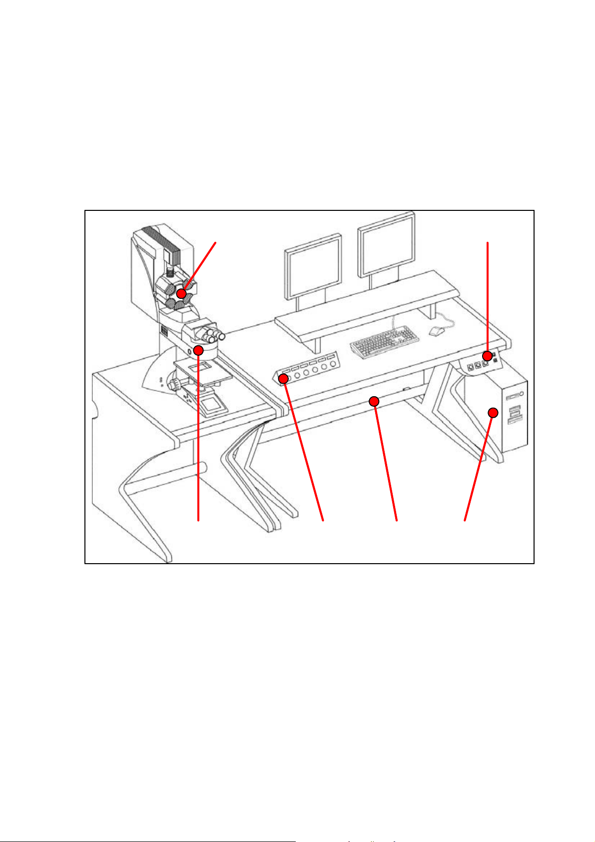
5.1 System overview
12
Specifications
6
figure1. System components (overview)
User Manual TCS SP5
V: 02 | Document-ID-No.: 156500002
5
1 TCS SP5 Scanner
2 Control panel
3 TCS workstation
4 Supply unit
5 Panel box
6 Stand with scanner
4
3
Page 11
Page 18
Specifications
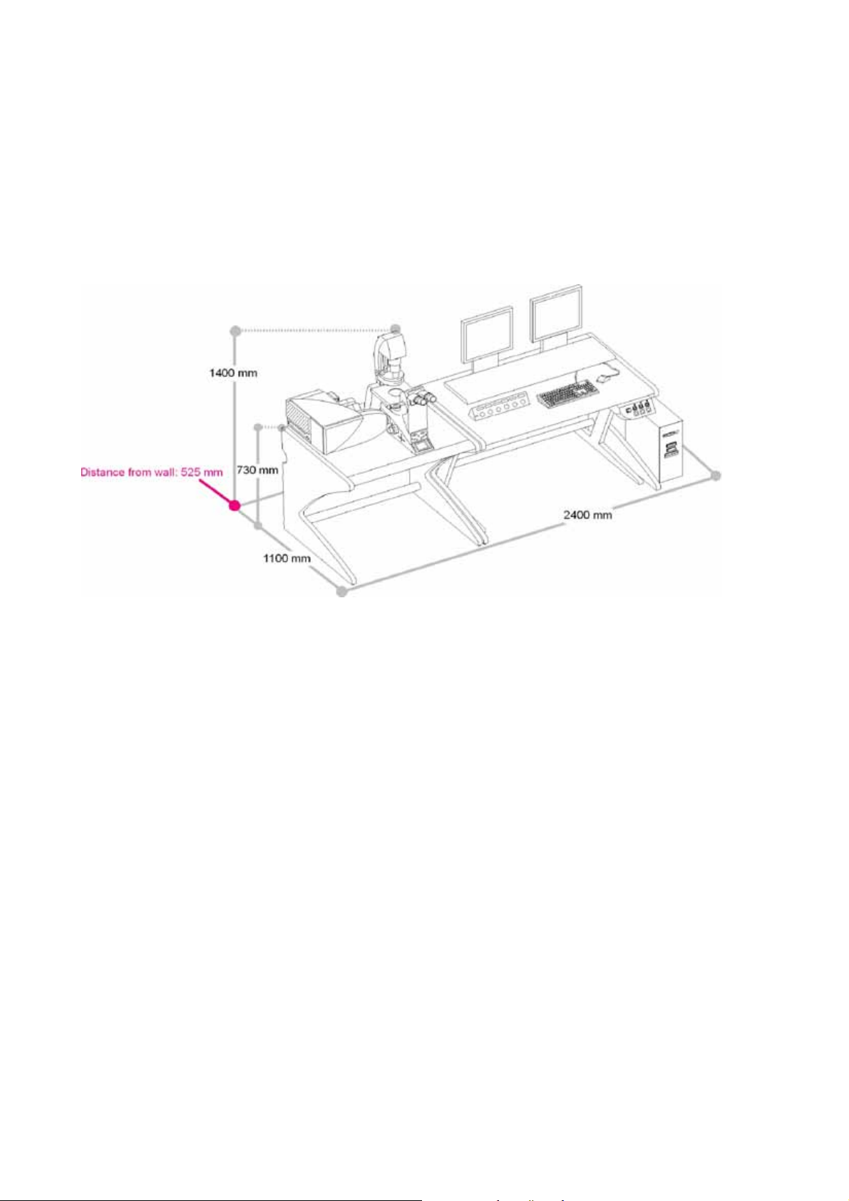
5.2 Dimensions
5.2.1 System with inverted stand:
figure2. Dimensions of the TCS SP5 with inverted stand
Page 12
User Manual TCS SP5
V: 02 | Document-ID-No.: 156500002
Page 19
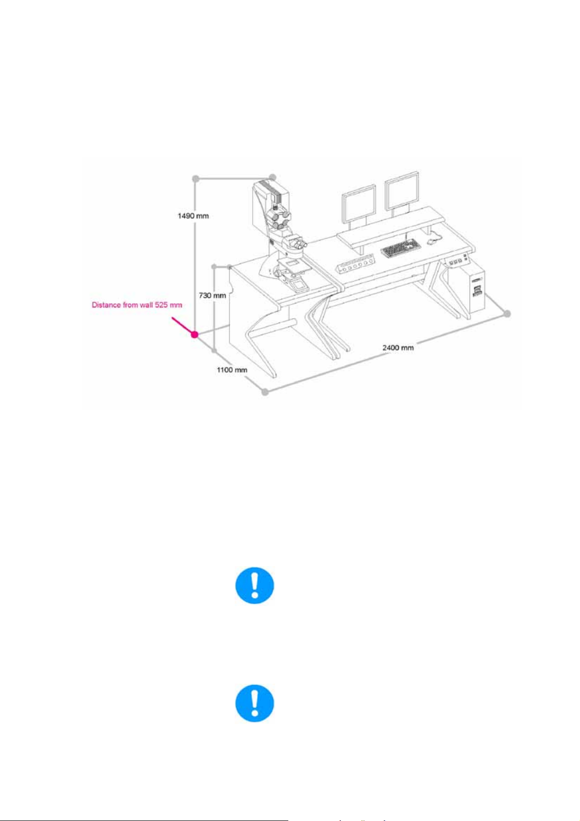
5.2.2 System with upright stand
Specifications
figure3. Dimensions of the TCS SP5 with upright stand
5.3 Installation site requirements
Do not expose the system to draft.
Ensure that the system is not installed next
to elevators, air conditioners or ventilation
systems. For this reason, the installation site
should be carefully planned.
Ensure that the e nvironment is as dustfree as possible.
User Manual TCS SP5
V: 02 | Document-ID-No.: 156500002
Page 13
Page 20

Specifications
Please also read the notes on protection
against dust in the chapters on maintenance
and cleaning. Installing the system in darkened rooms is also advisable.
For installation, maintenance and transport, the TCS SP5 system requires doors
with inside spans of 1.00 m.
With regard to the load-bearing capacity of
the floor, please note that the system will apply a static load of 200 kg/m@.
5.4 Permissible ambient conditions
Permissible temperature range for operation:
18 ... 25° C
Permissible relative humidity: 20-80% (noncondensing)
Permissible vibration speeds:
Frequency range [5 Hz–30 Hz]: less than 30
μm/s (effective value)
Frequency range [> 30 Hz]: less than 60
μm/s (effective value)
Pollution degree: Class 2
5.5 Electrical connections
Supply voltage (Input 1/Input 2): 100...240 V
AC +/- 10%
Frequency: 50/60 Hz
Page 14
Power consumption: 2 x 1.6kW
Overvoltage category: II
The building installation must feature two se-
parate power connections with the following
fuse protection:
D 100 V - 120 V AC power: 20 A
User Manual TCS SP5
V: 02 | Document-ID-No.: 156500002
Page 21

Specifications
D 200 V - 240 V AC power: 12-16 A
For the specifications of external lasers such
as UV and MP lasers, please refer to the manufacturer’s documentation.
User Manual TCS SP5
V: 02 | Document-ID-No.: 156500002
Page 15
Page 22

Specifications
5.6 Required cooling capacity
The TCS SP5 system has a maximum power
consumption of 3.2
kW (VIS system).
For the specifications of external lasers such
as UV and MP lasers, please refer to the manufacturer’s documentation.
5.7 Important additional notes
The optimal optical performance of the system can be achieved using standard objectives and standard immersions only at 22°
Celsius + 1 Kelvin.
Page 16
User Manual TCS SP5
V: 02 | Document-ID-No.: 156500002
Page 23

Specifications
5.8 Required safety measures for VIS and UV systems
Please observe valid country-specific regulations pertaining to laser safety measures for
laser class IIIb. The operator is responsible
for observing the laser safety regulations.
5.9 Required laser safety measures for MP systems
Please observe valid country-specific regulations pertaining to laser safety measures for
laser class 4/IV. The operator is responsible
for observing the laser safety regulations.
5.10 Important additional notes
The optimal optical performance of the systemcanbeachievedusing standard objectives and standard immersions only at 22°
Celsius + 1 °Celsius.
User Manual TCS SP5
V: 02 | Document-ID-No.: 156500002
Page 17
Page 24

Specifications
Page 18
User Manual TCS SP5
V: 02 | Document-ID-No.: 156500002
Page 25

6 Safety Notes
Safety Notes
The instrument is Class 3B or 4 laser
equipment
(depending on the laser used) in accordance with IEC/EN 60225-1.
This laser equipment may be operated
only by persons who have been trained in
the use of the systems and the potential
dangers of laser radiation.
As it is not possible to anticipate every potential hazard, please take care and apply
common sense to the installation, operation
and maintenance of this product. Observe all
safety precautions relevant to Class IIIb lasers and Class IV MP systems.
Do not deviate from the operating and maintenance instructions provided herein.
The failure to observe these instructions
shall be exclusively at the user’s own risk
and may void the warranty.
6.1 Which standards does this product meet?
This device was tested and meets the requirements of the following standards:
D IEC/EN 61010-1
”Safety requirements for electrical equipment for measurement, control and laboratory use”
D IEC/EN 60825-1
”Safety of laser products, Part
1: Equipment classification, requirements and user’s guide”
D IEC/EN 61326
”Electrical equipment for measurement,
control and laboratory use - EMC requirements” (Class A).
This is a Class A device. Operating this
device on a public low-voltage grid may
result in radio interference. The operator
User Manual TCS SP5
V: 02 | Document-ID-No.: 156500002
Page 19
Page 26

Safety Notes
must take suitable measures should this
occur.
D IEC/EN 61000-3-2 (EMC)
”Electromagnetic Compatibility” Part
3-2: Limits - Limits for harmonic currents
D IEC/EN 61000-3-3 (EMC)
”Electromagnetic Compatibility” Part
3-3: Limits - Limits - Section
3: Limits for voltage fluctuations and flikker in low-voltage networks.
D For use in the USA:
CDRH 21 CFR 1040.10:
Laser Products U.S. Food and Drug
Administration (FDA) (”Complies with
FDA performance standards for laser
products except for deviations pursuant
to laser notice No. 50, dated 26 July,
2001.”)
For the scope of the CDRH/FDA
(USA), the designation Laser Class
3B in the text must be replaced by IIIb
andClass4byIV.
Page 20
User Manual TCS SP5
V: 02 | Document-ID-No.: 156500002
Page 27
Safety Notes
6.2 Which laser class does the product have?
Laser
type
VIS 400 - 700 nm,
UV 350 - 700 nm,
MP 350 - 1050 nm,
Wavelength range Configuration Laser class
Combination of lasers
(visible laser
radiation)
(visible and invisible la-
ser radiation)
(visible and invisible la-
ser radiation)
from Chapter 6.11
(without lasers having wave-
lengths of 350 - 400 nm)
Combination of lasers
from Chapter 6.11
(VIS and UV lasers)
Combination of lasers from
Chapter 6.11 (VIS/UV lasers)
and Chapter 6.12 (IR lasers)
6.3 Laser class for VIS and UV systems
According to IEC/EN 60825-1, this laser
scanning microscope is a laser device of
Class IIIb.
3B / IIIb
3B / IIIb
4/IV
Avoidexposingeyesorskintodirectradiation.
6.4 Laser class for MP systems
According to IEC/EN 60825-1, this laser
scanning microscope is a laser device of
Class IV.
Avoidexposingeyesorskintodirectand
indirect radiation.
User Manual TCS SP5
V: 02 | Document-ID-No.: 156500002
Page 21
Page 28

Safety Notes
6.5 Warnings, Safety Cautions, and Notes
Notes either contain additional information
on a specific topic or special instructions on
the handling of the product.
A safety note points out an operation, a process,a condition oran instruction that must be
observed strictly to prevent severe damage to
the system or loss of data.
A laser warning points out an operation, a
process, a condition or an instruction that
must be observed strictly to prevent serious
eye injuries to the persons using the system.
A high-voltage warning points out an operation, a process, a condition or an instruction that must be observed strictly to prevent
possible injury or death of the persons using
the system.
Page 22
User Manual TCS SP5
V: 02 | Document-ID-No.: 156500002
Page 29

Safety Notes
6.6 What should the user of the laser scanning microscope observe?
The user of this product is responsible
for proper and safe operation and safe
maintenance of the system as well as for
following all applicable safety regulations. The user is
fully liable for all consequences resulting
from the use of the system for any other purposes than those listed in the Operating Instructions or the online help.
The user is obligated to perform and monitor suitable safety measures
according to IEC / EN 60825-1 and
the corresponding national regulations.
Users must have received instructions
concerning the risk potential associated with
the operation of laser devices.
To assure classification as a
3B/IIIb or 4/IV laser product according to
IEC/EN60825-1 and electrical safety compliance, all safety devices, interlocks, and
safety systems of the laser device must
be in operational condition.
Deactivating or damaging these safety devices or any intervention in any of these safety
devices may lead to serious eye injuries,
physical injuries or property damages. In
these cases, Leica Microsystems CMS
GmbH does not assume any liability.
User Manual TCS SP5
V: 02 | Document-ID-No.: 156500002
According to IEC/EN 60825-1:
”Safety of laser products, Part
1: Equipment classification, requirements
and user’s guide,” the user is required to
Page 23
Page 30

Safety Notes
designate a Laser Safety Officer or a Laser Protection Advisor.
Repairs and servicing may only be performed by authorized Leica Microsystems
CMS GmbH service personnel.
The user is fully liable for all
consequences resulting from the use of the
system if it is opened, improperly serviced or
repaired by other persons than authorized
Leica customer service representatives.
If repairs or service measures are performed that require opening parts of the
housing, only trained Leica service technicians may occupy the room in which
the laser scanning microscope is located.
Leica Microsystems CMS GmbH will not be liable for damages resulting from nonobservance of the
above information. The above information
does not, in any way, implicitly or explicitly,
modify the warranty and liability clauses contained in the general terms and conditions of
Leica Microsystems CMS GmbH.
Page 24
User Manual TCS SP5
V: 02 | Document-ID-No.: 156500002
Page 31
6.7 Safety Notes for the User
Read and observe the safety notes in the
Operating Instructions and the safety labels located on the system. Failure to
observe the safety notes may lead to serious
injuries and to significant damages to the system and loss of data.
Observe the instructions for operating the
system located in the Operating Instructions.
Safety Notes
Before performing operating steps for the
first time with the system, read the corresponding description of the function in
the online help first.
You can get an overview of the single functions in the contents file of the online help.
Do not connect any external equipment.
Connect only those electrical devices to the
productthatare listed in theOperatingInstructions. Otherwise, please contact your local
Leica service agency or Leica Microsystems
CMS GmbH.
User Manual TCS SP5
V: 02 | Document-ID-No.: 156500002
Page 25
Page 32

Safety Notes
6.8 Safety Notes for Operation
figure4. Specimen area of upright and inverted stand
During scanning, the laser radiation is
freely accessible after exiting the objective in the specimen area of the laser
scanning microscope.
This circumstance demands special attention
and caution. If the laser radiation comes in
contact with the eyes, it may cause serious
eye injuries. For this reason, prudent handling is absolutely necessary as soon as one
or several laser emission warning indicators
are lit.
If the laser scanning microscope is used as
prescribed and the safety notes are observed during operation, there are no dangers
totheuser.Maintainasafetydistanceof20
cm between your eyes and the eyepiece
opening.
Page 26
User Manual TCS SP5
V: 02 | Document-ID-No.: 156500002
Page 33

Safety Notes
Do not look into the eyepieces during the
scan process.
Do not look into the eyepieces when switching the beam path in the stand..
Never look directly into a laser beam or a
reflection of the laser beam. Avoid all
contact with the laser beam.
Never deactivate the laser protection devices. Please read the chapter ”Laser pro-
tection devices” to familiarize yourself with
the safety devices of the laser scanning microscope.
Do not introduce any reflective objects
into the laser beam path.
If, for example, micromanipulators are
used in the specimen area, you must
ensure that no uncontrolled laser light
leaves the safe beam path due to reflection or scattering during the scanning
process, as it could pose a hazard to the
surrounding area.
User Manual TCS SP5
V: 02 | Document-ID-No.: 156500002
Page 27
Page 34

Safety Notes
Do not change specimens during scanning.
Proceed as follows:
Upright microscope Inverted microscope
Finish the scan process. Finish the scan process.
Ensure that no laser radiation is pre-
sent in the specimen area.
Exchange the specimen.
Insert the specimen correctly into the
specimen holder.
Ensure that no laser radiation is present in the specimen area.
Tilt the transmitted-light arm back.
Exchange the specimen.
Insert the specimen correctly into the
specimen holder.
Tilt the transmitted-light arm back into
the working position.
Do not change objectives while scanning.
Should it become necessary nevertheless,
please follow these procedures:
1 Finish the scan process.
2 Rotate the objective turret so that the ob-
jective to be changed is swiveled out of
the beam path and points outward.
3 Exchange the objective.
- All unoccupied positions in the objective turret must be closed using the supplied caps.
Page 28
User Manual TCS SP5
V: 02 | Document-ID-No.: 156500002
Page 35

Do not change any filter cubes or beam
splitters during scanning.
Proceed as follows:
Upright microscope Inverted microscope
Finish the scan process. Finish the scan process.
Safety Notes
Remove the cover of the fluorescence
Pull out the fluorescence module.
module
(see Microscope Stand operating instructions).
Remove the filter cube/beam splitter. Remove the filter cube/beam splitter.
Insert the desired filter cube/beam split-
ter.
Reattach the cover to the front of the
Insert the desired filter cube/beam split-
ter.
Reinsert the fluorescence module.
fluorescence module.
Never disconnect an optical waveguide.
Never remove the scanner from the microscope stand during operation.
Before removing the scanner, the system
must be completely switched off.
User Manual TCS SP5
V: 02 | Document-ID-No.: 156500002
Do not use an S70 microscope condenser.The large working distance and the
low numeric aperture of the S70 microscope condensers could result in a threat
from laser radiation. Therefore, only S1
and S23 Leica microscope condensers
should be used.
Page 29
Page 36

Safety Notes
6.9 Specific Safety Notes
6.9.1 Operational reliability
This instrument must not be used together
with life-support systems such as those
found in intensive-care wards.
Thisinstrumentmayonlybeusedwitha
grounded AC power supply.
6.9.2 De-energizing the system
Contact with liquids or the entry of liquids
into the housing must be avoided.
The main circuit breaker is located on the
right rear side of the supply unit. It is used to
de-energize the complete system using a
single switch.
The main circuit breaker functions as a
switch and as an overcurrent fuse.
The main circuit breaker is not to be used as
the regular on/off switch for the system.
The supply unit must be set up so that the
main circuit breaker is freely accessible at
all times.
figure5. Supply unit with main circuit breaker
Page 30
User Manual TCS SP5
V: 02 | Document-ID-No.: 156500002
Page 37

Safety Notes
6.9.3 Maximum current load of the power outlet strip at the supply unit
The total power consumption of all loads
connected to the power outlet strip must not
exceed
800 VA.
The connectors are intended for:
D TCS control computer
D Monitor 1
D Monitor 2
D Microscope
figure6. Power outlet strip, rear side of supply unit
User Manual TCS SP5
V: 02 | Document-ID-No.: 156500002
Page 31
Page 38

Safety Notes
6.10 Laser safety devices
The light of all employed VIS lasers
(wavelength range 400-800 nm, visible spectrum
)andUVlasers(
wavelength range < 400 nm, invisible) is fed
through an optical waveguide and, therefore,
completely shielded until it leaves the microscope objective and reaches the specimen.
For MP systems, see the chapter “Shielding
for MP systems”.
6.10.1 Eye protection for VIS or UV systems
It is not necessary to wear eye protection. If
the device is used as prescribed and the safety notes are observed,thelimitofthelaser
radiation is maintained so that eyes are not
endangered.
For MP systems, see the chapter “Eye
protection for MP s ystems”.
Page 32
User Manual TCS SP5
V: 02 | Document-ID-No.: 156500002
Page 39
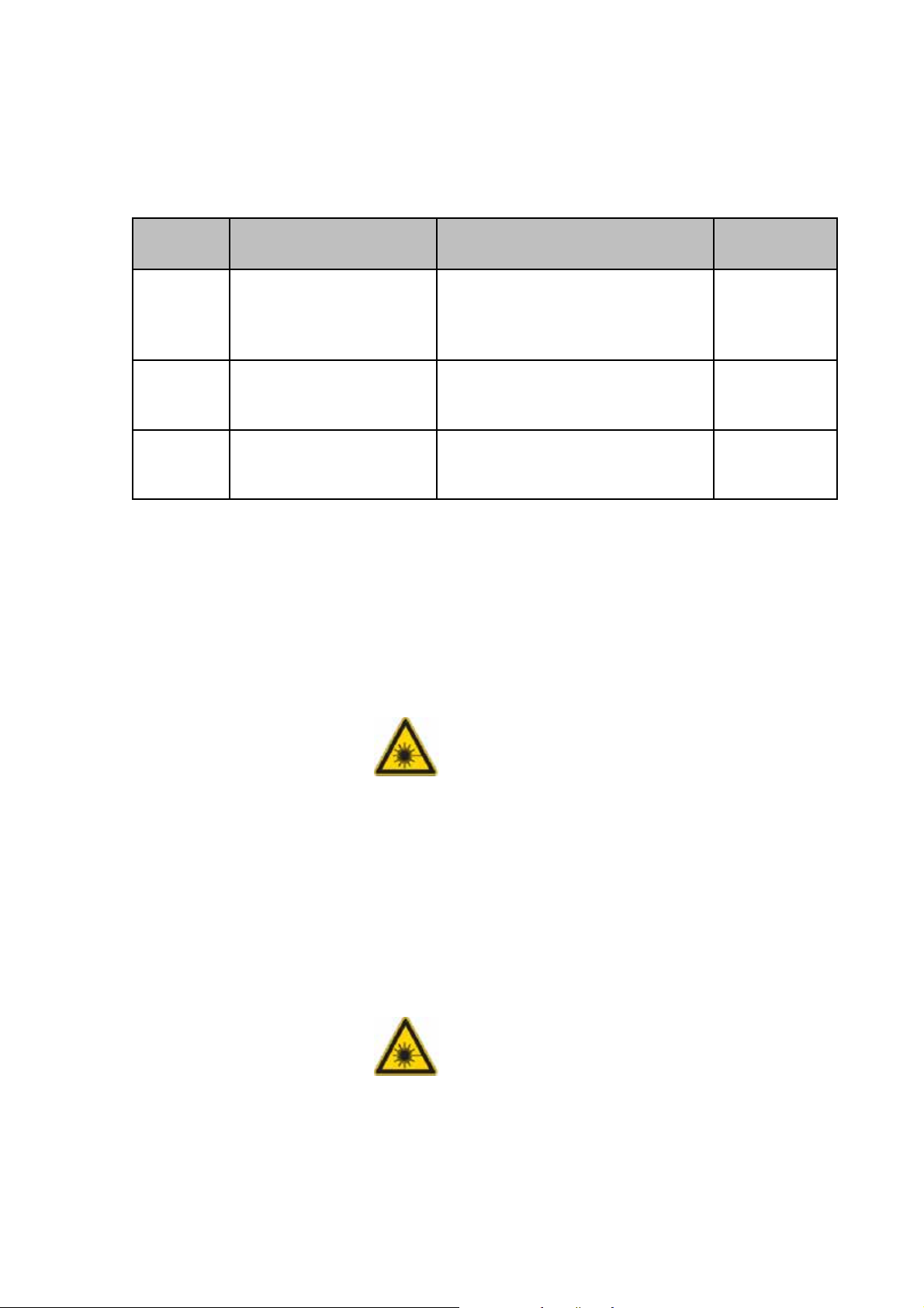
6.10.2 Detachable-key switch
Safety Notes
The detachable-key switch for protection
against unauthorized use of the laser devi ces is located on the control panel.
figure7. Detachable-key switch for the internal lasers
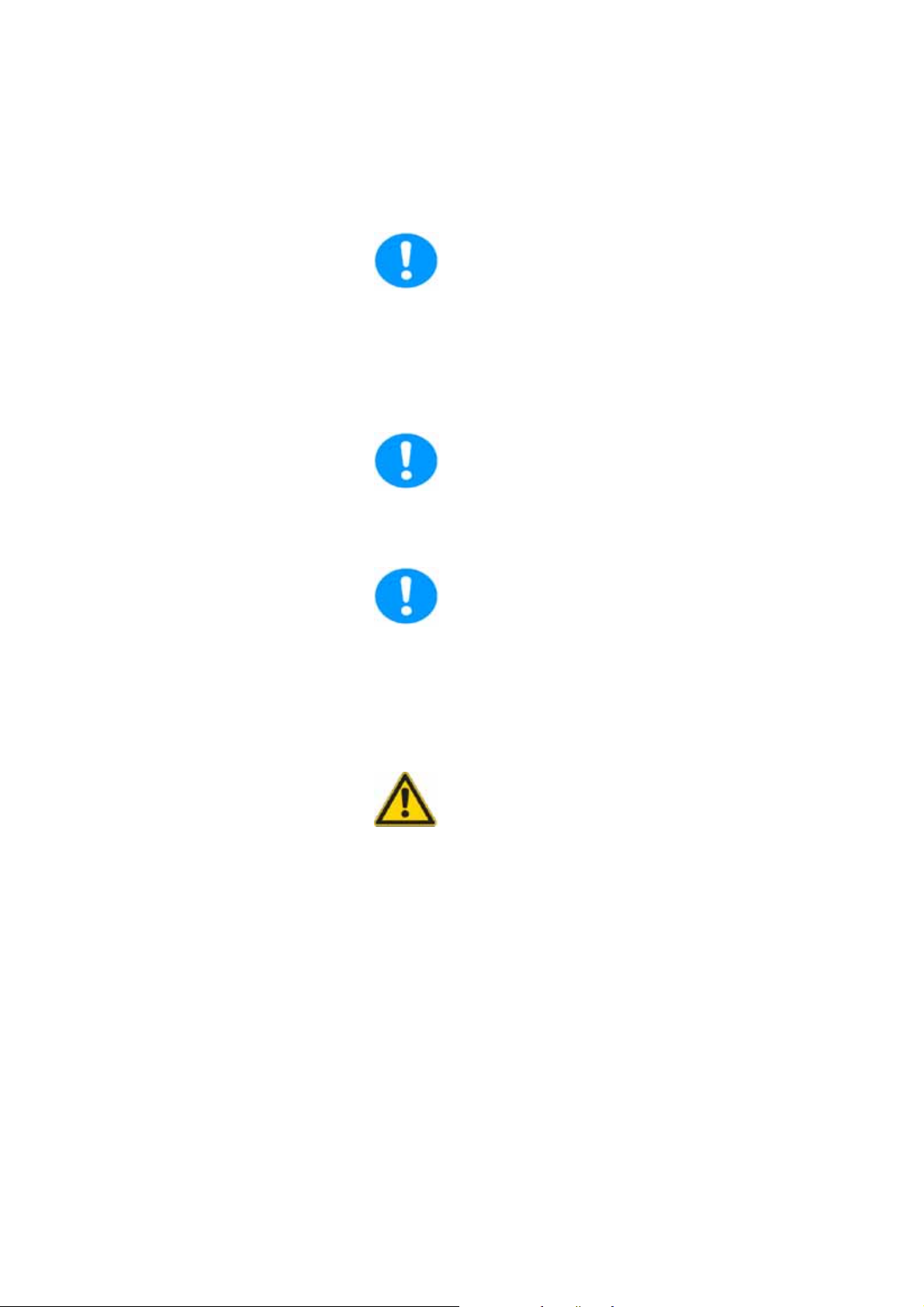
In the case of an optional external 405
nm advanced laser, the detachable-key
switch for the laser is located on its power
pack.
figure8. Detachable-key switch of the external 405-nm Advance laser
For lasers that are not connected as described above, please refer to the supplied
manual of the laser manufacturer for the
position of the detachable-key switches.
User Manual TCS SP5
V: 02 | Document-ID-No.: 156500002
Page 33
Page 40

Safety Notes
6.10.3 Emissions warning indicators
The operational readiness of lasers located
in the supply unit is signaled by an emission
warning indicator.
The emission warning indicator is located
above the detachable-key switch and is yellow when lit.
As soon as the emission warning indicator
of the lasers is lit, it is possible from a functional standpoint that laser radiation is present in the specimen area.
figure9. Emission warning indicators on the control panel
The optional external 405
nm advanced laser features the yellow
emission warning indicator (1) above the detachable-key switch.
figure10. Emission warning indicator of the external 405-nm Advance laser
Immediately disconnect the system from
the
power supply if any of the following occur:
Page 34
D The emission warning indicator is not lit
after being switched on using the keyswitch.
User Manual TCS SP5
V: 02 | Document-ID-No.: 156500002
Page 41

Safety Notes
D The indicator continues to be lit after
beingswitchedoffusingthekeyswitch
D Scanning of the specimen is not activa-
tedafterbeingswitchedonproperly(laser radiation in the specimen area).
Contact Leica Service immediately.
For lasers whose readiness is not indicated as described above, please refer to
the supplied manual of the laser manufacturer for the location of the emission warning indicator.
User Manual TCS SP5
V: 02 | Document-ID-No.: 156500002
Page 35
Page 42

Safety Notes
6.10.4 Remote interlock connector on the supply unit
figure11. Position of the remote interlock connector
Page 36
The remote interlock connection is located
on the rear side of the supply unit (
12V DC operating voltage). The remote interlock connector is plugged into this connection.
Remote interlocks that are connected to the
room, the door or other locally fixed safety
interlocks can be c onnected to the remote
interlock connection. The laser beam path is
interrupted if the contact is open.
The overall length of the cable between the
two connecting pins of the remote interlock
connector should not exceed 10 m.
User Manual TCS SP5
V: 02 | Document-ID-No.: 156500002
Page 43

Safety Notes
6.10.5 Remote interlock connector on the external 405nm advanced laser
If the laser scanning microscope is equipped with the optional 405-nm laser (non-pulsed), the “Interlock“ remote interlock connection is located on the rear side of the laser power supply.
The remote interlock connector contains a
shorting bridge.
Remote interlocks that are connected to the
room, the door or other locally fixed safety
Example/
interlocks can be connected to the remote
interlock connection.
The laser beam path is interrupted if the
contact is open.
figure12. Example of a remote interlock
The supply voltage of the remote interlock circuit of the 405 nm Advance laser
is 100-240V AC. For this reason, the remote interlock circuit of the 405
nm Advance laser must never be connected to other remote interlock circuits but,
instead, must be securely separated from
them.
Due to the live voltage of 100-240
V, replacing the shorting plug by an external interrupt circuit (e.g. door interlock
switch)
mayonlybeperformedbyaqualified
electrician.
6.10.6 Remote interlock connectors on additional external lasers
User Manual TCS SP5
V: 02 | Document-ID-No.: 156500002
Page 37
Page 44

Safety Notes
For lasers whose remote interlock connector is not indicated in Chapter 6.10.6,
please refer to the supplied manual of the
laser manufacturer for the location of the
remote interlock connector.
Page 38
User Manual TCS SP5
V: 02 | Document-ID-No.: 156500002
Page 45

6.10.7 Interlock connection on scanner
Safety Notes
figure13. Position of the interlock connector
The interlock connector (operating voltage
12 V DC) is located on the rear side of the
scanner.
The inverted microscope or, if an upright
microscope is used, the mirror housing is
connected to this connector. This ensures
that the safety switch of the microscope is
integrated in the interlock circuit.
User Manual TCS SP5
V: 02 | Document-ID-No.: 156500002
Page 39
Page 46

Safety Notes
6.10.8 Function and position of safety switches
When the safety switches are released, the
light path of the laser beam is interrupted.
1
2
figure14. Position of the transmitted-light illumination arm (1) and switching from scan mode to
eyepiece (2)
Position Activated by: Type of micro-
Activated if: Function
scope
1 Transmitted-
light illuminator
arm
Inverted stand
DMI 4000 CS
DMI 6000 CS
The illuminator
arm is tilted
(e.g. for working
Prevents laser light
while working on
the specimen.
on the specimen).
2 Motorized chan-
geover between
scanning mode
and eyepiece
Inverted stand
DMI 6000 CS
DMI 4000 CS
The deflection
mirror to the
scanner is motorized.
Prevents stray light
if the user switches
from confocal ob-
servationtoeye-
piece observation.
6.10.9 Transmitted-light lamp housing for inverted stands
Page 40
V: 02 | Document-ID-No.: 156500002
User Manual TCS SP5
Page 47

figure15. Cover for replacement flange
Safety Notes
Duringthetimewhennotransmitted-light
lamp housing is connected to the microscope stand, the opening must be tightly coveredwiththecapprovidedwiththesystem
to prevent laser radiation from exiting.
If your inverted stand features a transmittedlight housing that you would like to replace,
proceed as follows:
D Switch off the lasers.
D Disconnect the lamp housing from the
power supply.
D Remove the lamp housing.
D Perform the intended tasks at the lamp
housing.
D After finishing the tasks, screw the new
lamp housing back onto the microscope
stand.
figure16. Connecting the transmitted light lamp housing
To prevent the emission of laser radiation, do not switch the lasers on without a
lamp housing or cover on the microscope
stand.
User Manual TCS SP5
V: 02 | Document-ID-No.: 156500002
Page 41
Page 48

Safety Notes
6.10.10 Transmitted-light lamp housing for upright stands
During the time when no transmitted-light
lamp housing is connected to the upright microscope stand, the opening must be tightly
coveredwiththecapprovidedwiththesystem to prevent laser radiation from exiting.
figure17. Cover
If your upright stand features a transmittedlight housing that you would like to replace,
proceed as follows:
D Switch off the lasers.
D Disconnect the lamp housing from the
power supply.
D Remove the lamp housing.
D Perform the intended tasks at the lamp
housing.
D After finishing the tasks, screw the new
lamp housing back onto the microscope
stand.
figure18. Connecting the transmitted light lamp housing
To prevent the emission of laser radiation, do not switch the lasers on without a
lamp housing or mirror housing connected to the microscope stand, or if a cover
is not present.
Page 42
User Manual TCS SP5
V: 02 | Document-ID-No.: 156500002
Page 49

6.10.11 Mirror housing on upright stand
If a mirror housing is not connected to the
upright microscope stand, the opening must
be tightly covered using the cap provided
with the system to prevent any laser radiation from escaping.
Safety Notes
figure19. Cover
If your upright microscope stand is equipped
with a mirror housing, note the following:
D The interlock connector on the mirror
housing (see arrow) must be connected
to the scan head at all times.
D Theunusedoutputonthemirrorhou-
sing must be covered using the cover
provided (1).
D If the mirror housing is removed, place
a cover on the adapter left on the stand.
1
figure20. Mirror housing on upright stand
User Manual TCS SP5
V: 02 | Document-ID-No.: 156500002
To prevent the emission of laser radiation, do not switch the lasers on without a
mirror housing or cover on the microscope stand.
Page 43
Page 50

Safety Notes
6.10.12 Special laser safety equipment
6.10.12.1Safety beam guide and beam collector
The safety beam guiding and beam collector
3
2
are used with inverted microscopes to protect
againstlaser radiation andarelocated between
1
condenser base and transmitted-light detector.
1 Safety beam guide
2 Beam collector
3 Condenser base
figure21. Inverted stand
When subsequently ordering condenser
bases (3), be a ware that condenser bases
are supplied without beam collectors (2).
The existing beam collector (2) must be
reinstalled.
When using a condenser base with filter
holder, always make sure that unused filter holders are swung out of the beam
path, and that the
safety beam guide covers the beam path.
When equipping multiple filter holders
with filters, do so from bottom to top so
that the safety beam guide can cover the
beam path to the greatest possible extent.
Page 44
Do not swing in the filters during the
scanning process.
User Manual TCS SP5
V: 02 | Document-ID-No.: 156500002
Page 51

6.10.12.2Eye protection for MP systems
System with inverted microscope stand:
It is not necessary to wear eye protection.
If the device is used as prescribed and the
safety notes are observed, the limit of the laser radiation is maintained so that eyes are
not endangered.
System with upright microscope stand:
The IR laser beam can be deflected or scattered by the specimen or objects moved into
thespecimenarea.
Therefore, it is not possible to completely eliminate hazards to the eye from IR laser radiation.
Using protective eyewear
(specification: 680-990 DIR L5 / 990-1064
DIR L4) is required.
Appropriate safety goggles for IR laser radiation are provided w ith the system when delivered.
Safety Notes
The supplied eye protection only provides safe protection against the infrared
lasers supplied by Leica Microsystems
CMS GmbH.
User Manual TCS SP5
V: 02 | Document-ID-No.: 156500002
Page 45
Page 52

Safety Notes
6.10.12.3 Shielding in MP systems (UV laser)
The light of all employed VIS lasers
(wavelength range 400-700 nm, visible spectrum
)andUVlasers(
wavelength range < 400 nm, invisible) is fed
through an optical waveguide and, therefore,
completely shielded until it leaves the microscope objective and reaches the specimen.
For systems with infrared laser (wavelength
range > 700 nm), the beam is passed
through a safety beam guide and, if necessary, also passed through an optical waveguide.
This shields the laser beam until it leaves
the microscope objective and reaches the
specimen.
figure22. Safety beam guiding (1) and IR laser (2)
Page 46
User Manual TCS SP5
V: 02 | Document-ID-No.: 156500002
Page 53

6.11 Overview of usable VIS/UV lasers
The laser scanning microscope features a
combination of the lasers listed below.
Safety Notes
Laser type
Wavelength
[nm]
Maximum lumi-
nous power at
laser output
[mW]
Maximum lumi-
nous power in
focal plane
[mW]
Pulse duration
Ar-UV 351, 364 <60 <4 Continuous
wave (cw)
Diode 405 405 <60 <6 Continuous
wave (cw)
Diode 405 405 <5(
mean power)
<0.3(mean
power)
pulsed, 60 ps
DPSS 442 442 <25 <5 Continuous
wave (cw)
Ar 458, 476,
488, 496,
<200 <30 Continuous
wave (cw)
514
Ar, external 458, 476,
488, 496,
<500 <125 Continuous
wave (cw)
514
Solid state
488
488 <500 <150 Continuous
wave (cw)
HeNe 543 <1.5 <0.5 Continuous
wave (cw)
DPSS 561 561 <12 <4 Continuous
wave (cw)
HeNe 594 <4 <1 Continuous
wave (cw)
HeNe 633 <15 <4 Continuous
wave (cw)
Table 1 Table of usable lasers (without MP)
User Manual TCS SP5
V: 02 | Document-ID-No.: 156500002
Page 47
Page 54

Safety Notes
6.12 Overview of usable MP lasers (IR)
Each MP system contains only one of the
MP lasers listed below.
In addition, the MP system may also contain
additional VIS/UV lasers (see the table for
usable VIS/UV lasers).
Laser type Wavelength
[nm]
Maximum lumi-
nous power at
laser output
Maximum lumi-
nous power in
focal plane [W]
Pulse duration
[W]
TiSa* 780-920 <1.2 <0.6 pulsed, 1.0 -1.5
ps
TiSa* 710-920 <2.5 <1.2 pulsed
1.0-1.5 ps
TiSa* 710-990 <2.5 <1.2 pulsed
1.0-1.5 ps
TiSa* 720-930 <2.0 <1.0 pulsed
1.0-1.5 ps
TiSa* 720-980 <2.5 <1.2 pulsed
1.0-1.5 ps
Table 2 Table of usable MP lasers
* Modified picosecond version
Page 48
User Manual TCS SP5
V: 02 | Document-ID-No.: 156500002
Page 55

6.13 Safety label on TCS SP5 system
The corresponding safety labels are selected
dependent on the laser configuration (VIS,
UV, MP) and attached in the following locations.
6.13.1 Inverted stand DMI 4000/6000 CS
Angled rear view of right side of stand
Safety Notes
figure23. Safety label for DMI 4000/6000 CS inverted stand
User Manual TCS SP5
V: 02 | Document-ID-No.: 156500002
Page 49
Page 56

Safety Notes
52008–005 Zust.0188100–017 Zust. 00
figure24. Safety label for DMI 4000/6000 CS inverted stand
6.13.2 Upright stand DM 5000/6000 CS
Page 50
User Manual TCS SP5
V: 02 | Document–ID–No.: 156500002
Page 57

Safety Notes
Angled front view of right side of stand
figure25. Safety label for DM 5000/6000 CS upright stand
User Manual TCS SP5
V: 02 | Document-ID-No.: 156500002
Page 51
Page 58

Safety Notes
Rear view of stand
figure26. Safety label for DM 5000/6000 CS upright stand
Page 52
User Manual TCS SP5
V: 02 | Document-ID-No.: 156500002
Page 59

6.13.3 Scan head
Safety Notes
Angledfrontviewofleftsideofscanhead
figure27. Safety label for the scanner
User Manual TCS SP5
V: 02 | Document-ID-No.: 156500002
Page 53
Page 60

Safety Notes
6.13.4 Supply unit
View of TCS SP5 supply unit.
figure28. Safety label for the supply unit TCS SP 5 (front side)
Page 54
User Manual TCS SP5
V: 02 | Document-ID-No.: 156500002
Page 61

Safety Notes
6.13.5 External 405-nm laser Advance / 405-nm imaging laser
figure29. Safety label for the external 405-nm laser / safety label for the 405-nm imaging laser
User Manual TCS SP5
V: 02 | Document-ID-No.: 156500002
Page 55
Page 62

Safety Notes
6.13.6 External 488-nm laser
figure30. Safety label for the external 488-nm laser
Page 56
User Manual TCS SP5
V: 02 | Document-ID-No.: 156500002
Page 63

6.13.7 MP beam coupling unit
Safety Notes
Angled front view of the right side of the
beam coupling unit MP.
figure31. Safety label for the beam coupling unit MP (top side)
User Manual TCS SP5
V: 02 | Document-ID-No.: 156500002
Page 57
Page 64

Safety Notes
6.13.8 Cover (for replacement flange)
View from front on the cover.
figure32. Cover for replacement flange
If the replacement flange for transmitted
light is not equipped with a functional
module such as a lamp housing, place a
cover over the opening for laser safety
reasons.
Page 58
User Manual TCS SP5
V: 02 | Document-ID-No.: 156500002
Page 65

Safety Notes
6.14 Requirements related to the installation/storage location
This device was designed for use in a lab
and may not be set up in areas with medical devices serving as life-support systems such as intensive-care wards.
This equipment is designed for connection to a grounded (earthed) outlet. The
grounding type plug is an important safety feature.
To avoid the risk of electrical shock or damage to the instrument, do not disable
this feature.
To avoid the risk of fire hazard and electrical shock, do not expose the unit to
rain or humidity.
Do not open the cabinet. Do not allow any
liquidtoenterthesystemhousingor
come into contact with any electrical
components.
The instrument must be thoroughly dry
before connecting it to the power supply
or turning it on.
User Manual TCS SP5
V: 02 | Document-ID-No.: 156500002
Page 59
Page 66

Safety Notes
6.15 Changing the installation site
Before moving the laser scanning microscope, it should be thoroughly cleaned.
Thesamealsoappliestotheremovalof
components. This applies in particular to
systems that are located in biomedical research labs.
This is necessary to remove a possible
contamination and, thereby, avoid carryover of dangerous substances and pathogens and its accompanying risk of persons.
Pay not only attention to surfaces, but especially to fans and cooling devices since
dust can frequently accumulate at these
locations.
Page 60
User Manual TCS SP5
V: 02 | Document-ID-No.: 156500002
Page 67

6.16 Scanner cooling
Safety Notes
The scanner of the TCS SP5 is liquid-cooled.
Observe the attached safety data sheet pro-
vided by the manufacturer, Innovatek, regarding the coolant used.
In case of a coolant leak, switch the
power off immediately!
Inform Leica or a Leica-approved service
facility immediately.
The coolant contains an irritating substance. Avoid eye and skin contact.
The scanner cooling system must be serviced by Leica or a Leica-approved service facility every two years.
User Manual TCS SP5
V: 02 | Document-ID-No.: 156500002
Page 61
Page 68

Safety Notes
Page 62
User Manual TCS SP5
V: 02 | Document-ID-No.: 156500002
Page 69

7 Care and cleaning
Please refer to the corresponding manuals
for information on how to maintain the Leica
research microscope.
The instructions and additional information
relating to the components of the confocal
system are summarized below.
Protect the microscope from dust and
grease.
When not in use, the system should be covered with a plastic foil (part of delivery) or a
piece of cotton cloth. The system should be
operated in a room which is kept as dust and
grease-free as possible.
Care and Cleaning
Dust caps should always be placed over the
objective nosepiece positions when no objective is in place.
Exercise care in the use of aggressive
chemicals.
You must be particularly careful if your work
involves the usage of acids, lyes or other aggressive chemicals. Make sure to keep such
substances away from optical or mechanical
components.
7.1 Cleaning the optical system of the microscope
User Manual TCS SP5
V: 02 | Document-ID-No.: 156500002
Page 63
Page 70

Care and Cleaning
The optical system of the microscope must
be kept clean. Under no circumstances
should users touch the optical components
with their fingers or anything which may bear
dust or grease.
Remove dust by using an air puffer (not solvent-based) or a fine, dry hair pencil. If this
method fails, use a piece of lint-free cloth,
moistened with distilled water.
Persistent dirt can be removed from glass
surfaces by means of pure alcohol or chloroform.
If an objective lens is accidentally contaminated by unsuitable immersion oil or by the
specimen, please contact your local Leica
branch office. for advice on the use of certain
solvents for cleaning purposes.
Take this seriously, because some solvents
may dissolve the glue which holds the lens in
place.
Do not open objectives for cleaning.
Oil should be removed from oil immersion
lenses after use.
First,removetheimmersionoilusingaclean
cloth. Once most of the oil has been removed with a clean tissue, a piece of lens tissue
should be placed over the immersion end of
the lens. A drop of recommended solvent
should be applied, and the tissue gently
drawn across the lens surface. Repeat the
process until the lens is completely clean.
Use a clean piece of lens tissue each time.
7.2 Cleaning the microscope surface
Use a lint-free linen or leather cloth (moistened with alcohol) to clean the surfaces of the
microscope housing or the scanner (varnished parts).
Page 64
User Manual TCS SP5
V: 02 | Document-ID-No.: 156500002
Page 71

Care and Cleaning
Neveruse acetone, xyleneor nitro thinners
as they attack the varnish.
All LEICA components and systems are carefully manufactured using the latest production methods. If you encounter problems in
spite of our efforts, do not try to fix the devices or the accessories yourself, but contact
your Leica representative.
Before moving the confocal system, it
shouldbethoroughlycleaned.Thisapplies
in particular to systems that are located in
biomedical research labs.
This is necessary to remove any existing
contamination and to prevent any carry-over
and endangering of others. Pay not only attention to surfaces, but especially to fans and
cooling devices since dust can frequently accumulate at these locations.
User Manual TCS SP5
V: 02 | Document-ID-No.: 156500002
Page 65
Page 72

Care and Cleaning
Page 66
User Manual TCS SP5
V: 02 | Document-ID-No.: 156500002
Page 73

8 Startup of the system
Proceed as follows to start your TCS SP5
system:
1 Switch on the TCS workstation.
Startup of the System
figure33. Switching on the workstation
1
2
Check whether the microscope stand is
switched on.
If the readiness indicator (Figure 31/1) on
the MIC box is lit, the stand is operating.
If the readiness indicator is not lit, activate
the toggle switch (Figure 31/2) of the MIC
box.
figure34. Switching on the microscope
User Manual TCS SP5
V: 02 | Document-ID-No.: 156500002
You do not have to start the operating system—it starts automatically when you turn
on your PC. You will first see a splash
screen.
Page 67
Page 74

Startup of the System
1 Next you have to log on to your compu-
ter. As you can see from the instructions
in the box, pressing the Ctrl, Alt and Delete keys at the same time will log you
on. After pressing the Ctrl, Alt, and Delete keys, the Logon information dialog
box appears.
2 Typing your password identifies you as a
valid user for this computer.
The default user name for the Leica TCS
SP5 system is ”TCS_User”.
A standard password was not set. It is recommended setting up a separate user ID
for each user (system administrator). This
will create individual directories t hat can be
viewed only by the respective user. Since the
LCS AF software is based on the user administration of the operating system, separate
files are created for managing user-specific
profiles of the LCS AF software. For information about setting up users, please refer to
the chapter ”Setting Up Users” in this manual.
3 After logging on with your user ID, you
may change your password by pressing
thekeysCtrl,Alt,andDeleteatthe
same time.
4 Then click on Change Password. The
Change Password dialog box displays.
5 Type your current password in the ”Old
Password” field (passwords are case
sensitive, so be sure you use the right
case).
6 Then press the Tab key. Pressing the
Tab key moves the cursor to the next
field.
7 Type your new password, then press the
Tab key again. Confirm your new password by re-entering it. This will eliminate
any typing errors. This is especially important since the characters you type appear as asterisks on the screen.
Page 68
User Manual TCS SP5
V: 02 | Document-ID-No.: 156500002
Page 75

Startup of the System
8 Then click the OK button. Your new
password will be in effect the next time
you log on.
User Manual TCS SP5
V: 02 | Document-ID-No.: 156500002
Page 69
Page 76

Startup of the System
8.1 Setting Up Users
1 Log on as administrator. Us the ID
”Administrator” and the password ”Admin”
2 Open the User Manager. Select Start /
Programs / Administrative Tools / User
Manager.
3 Define a new user. Enter at least the fol-
lowing information in the open dialog
window:
D User name
D Password (must be entered again in the
next line for confirmation purposes)
4 Select the following two check boxes:
a.) ”User must change password at next lo-
gon” (this allows the new user to define his
or her own password at logon)
b.)”Passwordneverexpires”(thisallowsa
defined password to be valid either until it is
changed in the User Manager or the user is
deleted)
5 Select the ”Profiles” option in the bottom
section of the dialog. In the ”Local path”
field, enter the following path for storing
the user-specific file: d:\users\username
(”username” is a wildcard which must be
replaced by the currently defined user
name.)
Factory-installed hard disks are provided
with two partitions (C:\ and D:\). The user directory should be set up on partition D:\.
Page 70
User Manual TCS SP5
V: 02 | Document-ID-No.: 156500002
Page 77

Startup of the System
figure35. The ”booted” system
6 Wait until the boot process of the TCS
workstation is completed.
7 If not yet done, create a user and log on.
User Manual TCS SP5
V: 02 | Document-ID-No.: 156500002
Page 71
Page 78

Startup of the System
figure36. Turning on the scanner
8 Turn on the TCS SP5 scanner.
figure37. Turning on the scanner
Page 72
The Windows status bar must show the ”SP5
Scanner Gigabit Interface” as connected!
User Manual TCS SP5
V: 02 | Document-ID-No.: 156500002
Page 79

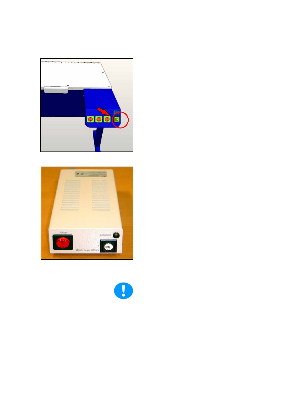
figure38. Switching on the laser
Startup of the System
9 Switch on the lasers.
The power supplies and fans of the system
start first.
10 Activate the detachable key switch.
figure39. Activating the detachable key switch
Laser radiation may be present in the
specimen area as of this time. Follow the
safety instructions given in Chapter 6.
Please follow the instructions in Chapter
14 to switch off the TCS SP5 system.
User Manual TCS SP5
V: 02 | Document-ID-No.: 156500002
Page 73
Page 80

Startup of the System
Page 74
User Manual TCS SP5
V: 02 | Document-ID-No.: 156500002
Page 81

9StartingtheLASAF
1 Start the LAS AF by double-clicking the
program icon.
Starting the LAS AF
figure40. Starting the LAS AF
User Manual TCS SP5
V: 02 | Document-ID-No.: 156500002
Page 75
Page 82

Starting the LAS AF
figure41. Resonant or non-resonant
If you purchased this option, you can
start the system in resonant or non-resonant mode at this point.
2 Select whether the TCS SP5 system
should be operated in resonant or non-
resonant mode.
Page 76
User Manual TCS SP5
V: 02 | Document-ID-No.: 156500002
Page 83

Starting the LAS AF
figure42. LAS AF start window
3 Start the LAS AF by clicking on ”OK”.
User Manual TCS SP5
V: 02 | Document-ID-No.: 156500002
Page 77
Page 84

Starting the LAS AF
figure43. LAS AF base view
You are now in the base view of the LAS AF.
4 Start the LAS AF help with the F1 key.
Page 78
User Manual TCS SP5
V: 02 | Document-ID-No.: 156500002
Page 85

Introduction to the LAS AF Help
10 Introduction to LAS AF -- Help
10.1 General
The LAS AF software is used to control all
system functions and acts as the link to the
individual hardware components.
The experimental concept of the software
allows for managing the logically interconnected data together. The experiment is displayed as a tree-structure in the software
and features export functions to open individual images (JPEG, TIFF) or animations
(AVI) in an external application.
10.1.1 Calling Online Help
The LAS AF software features a context-sensitive help system that explains the different
functions of the system.
The online help can be called in two ways:
D In the respective context (context-sensi-
tive)
D Via the Help menu
User Manual TCS SP5
V: 02 | Document-ID-No.: 156500002
Page 79
Page 86

Introduction to the LAS AF Help
10.1.2 Structure of the online help
The online help is divided into 6 different
books:
Books Contents
General This book contains general information about online help and
the contact information of the manufacturer.
Structure of the user inter-
face
This book describes the structure of the LAS AF user interface
and features topics about the various menus, registers, opera-
ting steps and symbols.
Dialog descriptions This book describes each individual dialog window of the user
interface in individual topics.
Learning the basics The fundamental steps for performing an experiment are des-
cribed here.
Guidelines This book contains step-by-step guidelines for performing cer-
tain applications. They are divided into two categories: for be-
ginners and for advanced users.
Additional information This book contains detailed descriptions about certain topics
of biology, image editing, filter...
Page 80
User Manual TCS SP5
V: 02 | Document-ID-No.: 156500002
Page 87

10.2 Imprint
Introduction to the LAS AF Help
Online help LAS AF; Version: 1.0
Address
Leica Microsystems CMS GmbH
Am Friedensplatz 3
68165 Mannheim
Phone +49-621-7028-0
Fax +49-621-7028-2980
Internet http://www.confocal-microscopy.com.
Copyright © 1997-2005 Leica Microsystems CMS GmbH. All rights reserved.
The contents of this online help may not be
reproduced or transmitted by electronic or
mechanical means, in whole or in part, without the express permission of Leica Microsystems CMS GmbH. This also includes
photocopying, recording or storing on a retrievable system as well as the translation
into another language.
Leica Microsystems CMS GmbH reserves
the right to revise this document and/or to
further develop and improve the products
described in this document at any time without prior notice or any other obligation. The
information and technical specifications in
this online help may be changed at any time
and without prior notice.
User Manual TCS SP5
V: 02 | Document-ID-No.: 156500002
Leica Microsystems CMS GmbH accepts no
responsibility for any errors or omissions. In
addition, Leica Microsystems CMS GmbH is
not responsible for direct, incidental or consequential damages that could result from
the use of the material described in this document.
Throughout this online help, trademarked names may be used. Rather than including a
trademark symbol (TM) at every occurrence
of a trademarked name, we state that we are
are using the names only in an editorial fashion, and to the benefit of the trademark
owner, with no intention of infringement.
Page 81
Page 88

Introduction to the LAS AF Help
10.2.1 In the respective context (context-sensitive)
1 Click on the small question mark located
in the top right corner of every dialog
window.
2 Online help opens directly to the descrip-
tion for the corresponding function.
10.2.2 Via the Help menu
1ClickontheHelp menu on the menu
bar. The menu drops down and reveals
the following search-based options:
Contents
This dialog field contains the table of contents in form of a directory
tree that can be expanded or collapsed. Double-click an entry of
the table of contents to display the corresponding information.
Index Enterthewordyouwanttolookup.Theonlinehelpshowsthekey
word that represents the closest match to the word you entered.
Select a keyword. View the corresponding content pages by
double-clicking the key word or selecting it and then clicking the
Display button.
Search Enter the term or definition you want to look up and click on the
LIST TOPICS button. A hierarchicallystructuredlistoftopicsisre-
turned.
Page 82
User Manual TCS SP5
V: 02 | Document-ID-No.: 156500002
Page 89

Introduction to the LAS AF Help
10.2.3 Full-text search with logically connected search terms
Click on the triangle to the right of the input
field on the Search tab to view the available
logical operators.
1 Select the desired operator.
2 Enter the second search term you would
like to associate with the first search
term behind the operator:
Examples Results
Pinhole and sec-
tions
Pinhole or sec-
tions
Pinhole near
sections
Pinhole not sec-
tions
This phrase finds help topics containing both the word ”pinhole” and the word
”sections”.
This phrase finds help topics containing either the word ”pinhole” or the word
”sections” or both.
This phrase finds help topics containing the word ”pinhole” and the word ”sec-
tions” if they are located within a specific search radius. This method also looks
for words that are similar in spelling to the words specified in the phrase.
This phrase finds help topics containing the word ”pinhole” and not containing the
word ”sections”.
User Manual TCS SP5
V: 02 | Document-ID-No.: 156500002
Page 83
Page 90

Introduction to the LAS AF Help
10.3 Key combinations
In order to accelerate recurring software
functions, special key combinations have
been defined:
CTRL + N
Opens a new experiment
CTRL + O Starts the Open dialog window to open an existing file.
Page 84
User Manual TCS SP5
V: 02 | Document-ID-No.: 156500002
Page 91

Introduction to the LAS AF Help
11 Structure of the user interface
11.1 General structure of the user interface
The user interface of the LAS AF is divided in five areas:
1 Menu bar: The different menus for cal-
ling functions are available here
2 Arrow symbols: Operatingstepwiththe
individual functions. These operating
steps mirror the typical sequence of an
image recording and subsequent image
processing. The functions are arranged
appropriately in these operating steps.
D Configuration
D Acquire
D Process
D Quantify
D Application
3 Tab area: Different tabs belong to every
operating step (arrow symbol) in which
the settings for the experiment can be
made.
User Manual TCS SP5
V: 02 | Document-ID-No.: 156500002
Page 85
Page 92

Introduction to the LAS AF Help
Acquire Experiments: Directory tree of opened files
Setup: Hardware settings for the current experiment
Acquisition: Parameter settings for the image recording
Process Experiments: Directory tree of opened files
Tools: Directory tree with all the functions available in the respective operating
step
Quantify Experiments: Directory tree of opened files
Tools: Tab with the functions available in this operating step
Graphs: Graphical display of values measured in regions of interest (ROI)
Statistics: Display of statistical values that were determined in the drawn in re-
gions of interest (ROI)
4 Working area: This area provides the
Beam Path Settings dialog window in
which the control elements for setting
the recording parameters are located.
5 Viewer window : Displays the recorded
images. In the standard setting, the Vie-
wer window consists of the image win-
dow in the center and the buttons for
image editing (5a) and channel display
(5b).
Page 86
User Manual TCS SP5
V: 02 | Document-ID-No.: 156500002
Page 93

Koehler Illumination
12 What is the Köhler illumination?
In a microscopic image, only a certain area
of a specimen can be displayed (image
field). Köhler illumination allows for illuminating only this particular area. The technical
background for the illumination of the image
field is described as follows:
If the illuminated area is smaller than the
image field, the luminous cone detected by
the objective lens as well as the numeric
aperture becomes smaller. Since the optic
resolution is directly dependent upon the numeric aperture, a lower illumination also reduces the optic resolution—which is not desired in most cases.
If the illuminated area is larger than the
image field, it leads to increased scattered
light. This, in turn, leads to a reduction of the
image contrast, possibly resulting in the situation where optically dissolved structures
of the microscopic image can no longer be
observed.
Köhler illumination represents a compromise
between maximum contrast and maximum
resolution. The most efficient microscope objectives frequently reach their optimum optic
performance only with exactly adjusted Köhler illumination.
User Manual TCS SP5
V: 02 | Document-ID-No.: 156500002
Page 87
Page 94

Koehler Illumination
12.1 Setting the Köhler Illumination
1 Focusing: Focusanareaoftheobject.
Neglect the quality of the illumination for
the time being
2 Opening the aperture diaphragm:
Fully open the aperture diaphragm. It will
be closed at a later point in time until the
desired contrast is adjusted.
figure44. DMxxxx (left) / DMIxxxx (right)
figure45. Field diaphragm
3 Closing the field diaphragm.
The image field darkens in most areas. You
will see an unfocused light spot. If the spot
disappears upon closing the field diaphragm, the field diaphragm must be centered. In this case, open the field diaphragm
until you can just see the light spot at the
border of the image field.
Page 88
User Manual TCS SP5
V: 02 | Document-ID-No.: 156500002
Page 95

Koehler Illumination
If no light spot is visible, the condenser
could be set to the wrong height. You
should, therefore, adjust the height of the
condenser until the field diaphragm is visible.
4 Focusing
Focus the border of the light spot by adju-
sting the height of the condenser.
5 Centering
Turn the centering screws of the condenser
until the light spot is centered in the middle of
the image field. The centering is easier if you
slightly open the field diaphragm to enlarge
the light spot.
6 Opening the field diaphragm
Open the field diaphragm until the light spot
just disappears at the border of the image
field.
7 Closing the aperture diaphragm
Close the aperture diaphragm until you have
set the desired image contrast (open to approximately 70% of the maximum diameter).
8 If you change the objective
It may become necessary to readjust the
Köhler illumination after you have changed
the objective.
User Manual TCS SP5
V: 02 | Document-ID-No.: 156500002
Page 89
Page 96

Koehler Illumination
Page 90
User Manual TCS SP5
V: 02 | Document-ID-No.: 156500002
Page 97

Introduction to Confocal Work
13 Introduction to confocal work
13.1 Preparation
The following sections describe a number of
basic procedures that cover most of the
tasks related to the instrument.
Upright stand
Stage
Focus
Lens
Focus
Objective
Coverslip
Seal
Glass slide
Embedding
Specimen
Immersion
Inverted stand
figure46. Arrangement of coverslip and specimen on an upright microscope (top) and inverted
microscope (bottom). When using objectives with coverslip correction, ensure that the
coverslip (i.e. the top side of embedded specimens) is facing down.
Background information has also been provided to explain the reasons behind various
settings. These are not descriptions of the
User Manual TCS SP5
V: 02 | Document-ID-No.: 156500002
Page 91
Page 98

Introduction to Confocal Work
13.1.1 The objective
individual functions and controls of the instrument and graphical user interface, but an informative tour of the essential tasks that is
designed to remain valid even if future upgrades change the specific details of operating the instrument.
Theveryfirststepistoplaceaspecimenin
the microscope, of course. When placing
specimensinaninvertedmicroscope,ensure that fixed specimens on slides are inserted with the coverslip facing down
(Fig.43). Failing to do so is a frequent reason
for not being able to find the specimen or focus on it in the beginning.
Medium Refractive Index
Water Imm 1,333
PBS Emb 1,335
Glycerol 80% (H2O) Imm 1,451
Vectashield Emb 1,452
Glycerol Imm 1,462
Moviol Emb 1,463
Kaisers Glycerol Gel Emb 1,469
Glass Mat 1,517
Oil Imm 1,518
Canada Balsam Emb 1,523
Table3 Immersionmedia
Select the objective with which you want to
examine the specimen initially.
When using immersion objectives, ensure
that an adequate quantity of immersion medium is present between the front lens of the
objective and the specimen. Immersion oil,
glycerol 80% and water may be used as immersion media (Table 3). Apply the immersion medium generously, b ut be sure that it
does not flow into the stand of inverted microscopes.
Page 92
User Manual TCS SP5
V: 02 | Document-ID-No.: 156500002
Page 99

13.1.2 Conventional microscopy
Toviewthespecimenconventionally through
the eyepieces, select ”VISUAL” operating
mode. ”SCAN” is for use with the laser scan
image process. Select a suitable position
and focus on the specimen.
Introduction to Confocal Work
Specimen
Objective lens
Shutter
Lamp
Filter cube
Eyepiece
figure47. Incident light fluorescence scheme: light from a mercury lamp is collimated, selected
spectrally via an exciter filter and applied to the specimen via a color splitter mirror. A
shutter permits the specimen to be darkened. The emission (longer wavelength than
the excitation) is visible through the color splitter mirror and emission filter via the eyepiece. The exciter filter, color splitter mirror and emission filter are grouped in a filter
cube.
Optical sections are created using a transmitted-light process. Your specimen must
therefore reflect or fluoresce. Fluorescent
specimens are most common. In many cases, specimens with multiple stains will be
examined. Reflective specimens can also
provide interesting results, however.
Filter cubes
(Fig. 44)
suitable to the fluore-
scence must be positioned in the beam when
User Manual TCS SP5
V: 02 | Document-ID-No.: 156500002
Page 93
Page 100

Introduction to Confocal Work
viewing the specimen via the eyepieces. For
more information on selecting fluorescence
filter cubes, please refer to the Leica fluorescence brochure or contact your Leica partner. For a selection of filter cubes, see Table
4 below.
As specimen fluorescence can fade quickly,
always close the shutter of the mercury lamp
when you are not looking into the microscope.
To switch to scan mode, press the appropriate buttons on the stand or use the switching function in the software. The switching
function may vary according to the motorization of the microscope. Please consult help
for more information.
Page 94
User Manual TCS SP5
V: 02 | Document-ID-No.: 156500002
 Loading...