

Page 1

Installation
Interface
Trouble Shooting
Maintenance
Technical data
International Service
Special Features
Lists
February
1998
3508
87993
Specifications
be
changed
without
prior
notice.
Page 2

The prudent mariner
will
never rely solely on any single means of
navigation.
He
will
always
use
whatever information
available.
The Global Positioning System
(GPS)
is
developed and operated by
the United States Department
of
Defense (DOD).
Only part of the
system
is
available
for
civil applications.
The
expected position accuracy
is
better than
meters for
percent
of
the time; but may be up
to
300
meters occasionally. The derived
speed
and
be
hampered
accordingly.
The availability and precision
will
be
kept within the stated
limits
as
far
as
the
military
and
political situation
allows.
The
and
are
prepared for direct connection
to
a
DGPS
Beacon Receiver
1000).
The
will for this purpose
need
a
DGPS
software upgrade and a new interface cable allowing
data
input. The position accuracy
is
hereby improved to better than
meters
for
95%
of
the time subject to availability
of
DGPS
transmissions
from
public Radio Beacons.
note that a position obtained from a chart
is
not always
as
as
your na~~~ator, and
that
the
position of
a
ai
rift. In addition the
such
as
Page 3

interface to Other Equipment
NMEA
Hardware Schematics
NMEA
Sentences
Trouble Shooting Guide
Navigator Self
-
test
Signal
Quality
Control
Maintenance
Software
Update
Technical
Data
International Service, Main Distributors
Glossary
of
Terms
About
Position Store Feature
Fast
Access
to
Contrast
and
Back
Light
Setting
Pass Criteria
Lists
4
page
page 12
page 19
page
page
23
page 25
page
27
page
28
page
32
page
34
page
38
page
39
page
39
page
42
page
43
3
Page 4

The
MK8
Navigators are designed for installation both above and below
deck. The
unit
I
S
fully splash proof
but
not watertight. The installation should
in
the
first instance meet the requirements of
the
or
the crew,
but
secondarily the site should be a smooth and flat nearly vertical surface to
insure
that
the
gasket around the holes for connection plugs and fixing screws
are waterproof. Please ensure that the navigator
is
mounted
in
a place where
water easily flows
off.
Never install
it
in
a place where the navigator
will
be
below
water
for
any
period
of
time.
Two
installation accessories
are
optionally
available:
A
Flush Mounting
Kit
and a Mounting Bracket (please see the chapter
containing technical data page
Insert the battery cell
in
the battery compartment on the back of the navigator.
Please refer to
the
instruction on
page
2
The
navigator has two connectors.
A
D-SUB
for power and data and a
connector
for the antenna
signal:
A.
9
pin
D-SUB
Pin No.
1
2
3
4
5
7
8
9
Screen
12345
F
connector.
RF
signal
from
antenna.
Stripping
information:
REF
Reference
for
MOB
signal. Connected
to
navigator
shield.
NMEA
listener
A
(input).
NMEA
talker A (output).
1.
y.
External
power.
2.
3.
NMEA
listener
B
(input).
4.
an
Board)
signal.
For
service use only.
NMEA
talker
(output).
battery. External
power.
NMEA
talker cable.
2
8
3.
Strip the antenna
cable.
back
the shield.
Screw
connec
-
tor
on.
The
con
should
peep
out
2
P
O
3
from the
connector
nut.
shown on the next page
Page 5

Figure
2.
not
in
the
kit.
fuse
can
IN
and
cables are
included
in
standard
PO
Amp.
Page 6

A
template
is
in
the installation kit. Place the 'Drilling Template
for
MK8
&
where you want your
unit
installed. Be sure that you have access
to back side
for
tightening the nuts.
Recommended
tools
for
installation.
Toots:
*
Adjustable spanner
*
*
Drill
*
Drill
7mm
Electric power
drill
Hand file
Use:
To
tighten the nuts.
Hole
for
antenna mounting.
Holes for D
-
SUB connector.
Holes for mounting stays.
To
smooth the hole for the
5-SUB
connector
The
navigator
is
designed for
12V
or
24V
battery supply,
but
the
unit
will
work
with
any
voltage from
to
32V.
The installation kit includes a 9 socket
D-SUB
connector mounted
with
all the
necessary cabling. The Power Cable is a joint
RED
and BLACK pair:
BLACK wire (D
-
SUB socket
should be connected to the minus
pole
of
the battery.
RE5
wire (D-SUB socket
should be connected to the plus pole of the
battery.
Please be sure to have a fuse
in
the circuit
not to protect the navigator
-
but
to protect
the
cabling. (Short-circuiting a cable with direct connection
to
a
battery
make severe damage). A typical installation
is
in
figure
page
5.
The electronics
of
the navigator
is
isolated
from
the external power supply.
It
is
recommended
to
ground the shield
of
the navigator
to
avoid static charge
built
up.
This can
be
done
in
one
of
two ways:
the
D-SUB
pin
of
the
navigator
to
boat's seawater
ground.
(nut
etc.) to the boat's seawater
ground.
'Seawater ground' is any structure
in
connection
with
the sea below the water
-
line. The connection could be through
a
10
Antenna mounting
and
navigator shield
is
electrically connected through
the
screen
of
the antenna cable.
To
avoid current loops do only
use
one
of
the two
grounding methods.
If
the antenna
is
mounted on the push
pit
or
similar metal
structure
we
recommend using that
part
for
grounding of the navigator
(possi
-
bly
by connecting
it
to
boat's
seawater ground).
Page 7

7
Page 8

The
and
navigators have two independent possible interfaces.
A
Man
Over Board input and
an
NMEA
0183
version
2.0
Board
A
push button
for
an
switch) (optional) can
be
connected between
the
Man
Over
Board
input
pin
and
the
REF
GND
(D-SUB
pin
1).
The installation
kit
includes
a
socket
D-SUB
connector mounted
with
all
the
necessary cabling. The
Man
Over Board
is
either a joint BLACK pair with one
wire marked with
an
embossment
or
a
joint GRAY pair with one wire marked
with
a
black stripe.
The
pair
should
be
connected to a push button that
is
normally
off
(not short-circuited). To enable the Man Over Board function
the
switch must be activated
for
at
least 2 seconds.
Please be aware,
that
the
unmarked
wire
of
this
pair
is
connected to
the
shield
of
the
navigator. A typical installation
is
shown
in
figure 2 page
5.
See
also
figure
4
below
if
using
the
Philips
NMEA
0183
Repeater
Display for
the
Man
Over Board function.
interface
The standard marine interface
NMEA
0183
version
2.0
is
used
for
Radars, Plotters, Autopilots, Fish Finders etc.
Philips
NMEA
01
83
Repeater Display
Philips Chart Plotters
PCP
207
and
PCP
21
1
Philips
DGPS
Beacon Receiver
1000
DGPS
Beacon Receivers transmitting RTCM
data
baud).
There should be no problem
in
interfacing
to
other instruments. Version
2.0
of
the
NMEA
0183
interface
has
been changed in several ways compared
to
the
earlier
version 1.5. Same
of
the
changes to
the
hardware
should
be
mentioned
in
order
to
avoid problems.
The listener input
now
with
a
2
cornpared
t
4
volt.
It
still
an
isolated
input and
in
general
any
problems.
output
is
now
a
talker (output)
is
output. That means:
tive compared to
naviga
-
tor.
In
the
old
version output
was
normally
tied Po
or
shield.
The maximum drive voltage between
NMEA
talker
A
and
outputs
volt.
The
minus voltage between the talker A and
B
some
problems on
inputs
that does not fulfill the
old
The
as
2
This
is
not ~o~~~t~~~~
4
volt
If
Page 9

More
than one
NMEA
listener can be connected
in
parallel to
the
NMEA
talker.
The possible
maximum
is
dependent on
the
listener input impedance.
A
typical
installation
is
shown
in
figure
4.
ii
0
m
W
0
Page 10

Interface
to
The Philips
NMEA
0183
Repeater Display should be connected to the navigator
as
in
figure
5.
(Connections are specified on page
not
9
POL
D
SUB
Figure
5
Please
note
NMEA
talker (output)
should
be connected to
the
Repeater Display
but
left open.
The shield of
the
NMEA
talker cable
is
connected to shield of the navigator and
should
Be
careful
that
neither the NMEA talker
wire
nor
the
shield
of
the
NMEA
talker cable are short-circuited to each other or anything else.
The
NMEA
version
2.0
standard requires that a schematic showing the imple
-
mentation
of
the listener and talker interface are included
in
the manual.
ther Equipment
NMEA
Listener
NMEA
I
Figure
Listener
input
load
threshold of
the
EA
output
with a drive
NMEA listener
is
2
connected
the
NMEA
listener
(D-SUB
pin
2 and
it
recommended to insert
a
be
up
to 500ohm per volt the
voltage
he
overall power consumption.
Page 11

Recommended external serial resistor value (see figure 6 previous page) for
the
NMEA
listener interface. Table
1
:
Drive Resistor
voltage value
3
volt
470
Ohm
1.0
KOhm
5
volt
1.5
KOhm
6
volt
1.8
KOhm
Drive Resistor
voltage value
8
volt 2.7
KOhm
9
volt
3.3 KOhm
10
volt
3.9 KOhm
11
volt
3.9 KOhm
I
12
volt
4.7
7
volt 2.2 KOhm
EA
talker
(output)
hardware
schematic
NMEA
talker
-
5v
A
DATA
B
*
Shown
in
normal
position
REF
GND
NMEA
POSITION
POSITION
(SERVICE
ONLY)
-
Talker maximum drive current
is
Figure
Both talker A and talker
outputs are active!
Connected to an
NMEA listener: Connect talker
A
to listener A and talker
to
listener
Connected to a
RS
422
port:
Connect talker
A
to
+receive
and
talker
to
-
receive.
Connected
a
232
port):
talker
A
Receive
Ground.
11
Page 12

E
and
The
NMEA
Standard provides
for
asynchronous transmission,
with
a single
TALKER
and
per line. Typical use includes information
transfer from
onic positioning and navigational devices to autopilots,
plotters, terminals, printers, etc.
The
NMEA
01
83
Standard
uses
an
8
bit
ASCII
block
oriented
protocol,
that
is
not
compatible
the
NMEA
0780
simple
format or
the
NMEA
0182
com
-
plex format due to differences
in
data format, baud rate and parity
bit.
The recommended interconnection between a
TALKER
and one or more
be
made
as
shown and described on
the
previous 4 pages.
Data
Format.
Data are transmitted
in
different sentences, each containing one or more data
fields.
A
field consists of a string of characters immediately preceded
by
a
character,
except
for
the
first (address)
which
is preceded
by
Hex
OD
OA
-
end of sentence
must follow
the
last fieid
in
each
sentence.
The
data
fields
are
identified only by their position within the sentence as
determined by
the
field delimiters (comma). Numerical data fields within
a
sentence may vary
in
length
from one sentence to another, depending on
the
precision avail able.
Data
field position
is
therefore determined only
by
counting
(commas) rather
than counting the total number of characters from beginning of the sentence.
Example:
field
2
34
56
$
N,
01236
07,
E
Sentence terminator
Optional
checksum
(HEX),
not
data field
Checksum
delimiter
Latitude
Address
GP = TALKER
identifier
GPS
GLL
=
Sentence formatter
Geographic
Latitude and Longitude
Start
of sentence delimiter
The
sentences
all
have
the
TALKER
identifier
determined position data are
in
the user selected datum; waypoint
positions reflect the content of the way point memory.
i
t
12
Page 13

ACCORDING
TO
NMEA
83,
VERSION
OF
1992,
JANUARY
1552.
RMC
-
Recommended
Minimum
Specific
GPS
data:
Time, date, position, course and speed data provided
by
the
-
er. Checksum
is
mandatory
in
this sentence. This sentence
is
transmitted at
intervals not exceeding
2
seconds, and
is
always accompanied
by
RMB when
a
destination waypoint
is
selected.
All
data fields must be provided,
null
fields
used only when data are temporarily unavailable.
field:
2
34
56
78
9
10
11
12
13
1111.111,
explanation:
2.
of
position
fix
3.
Status
A
or
V,
A
if
updating
is
OK,
V
if
updating
is
stopped
4.
Latitude
of
fix
5.
North
or
South,
Longitude
of
fix
7.
East
or
West, E/W
8.
Speed over ground, Knots
9.
Track made good (COG), degrees true
Date:
Day,
Month
and
Year
1
1.
Magnetic variation, degrees
12. East or West,
13. Checksum delimiter and checksum
RMB - Recommended
Minimum
Navigation Information:
Navigation data
from
present
position
to
the
first
destination
waypoint
in
the
sailplan. This sentence always accompanies the RMC, when a destination
waypoint
is
selected. Checksum is mandatory
in
this sentence.
field:
2
3
45
6
7
10
11
12
13
11111,
explanation:
2.
Status
A
or
V,
A
if updating
is
OK,
V
if updating is stopped
3. Magnitude
of
cross-track-error, nautical miles (see
Note
4.
Direction
to
steer,
L
or
R
5.
Origin waypoint identifier
6.
Destination
waypoint
identifier
7.
Destination waypoint latitude
8.
North
South, NE
9.
Destination waypoint longitude
10.
East
or
West,
Range
to
destination waypoint. nautical miles (see Note
12. Bearing to destination, degrees true
13.
Destination closing velocity, knots
14.
Not transmitted
from
the
15.
Checksum delimiter and checksum
Note
1:
if the
exceeds 9.99
Nm,
9.99
be
sent
Note
2:
if the range exceeds 999.9
Nm,
999.9
will
be
sent
Page 14

-
Autopilot sentence
Commonly used
by
autopilots, this sentence contains navigation receiver
update status, cross
-
track error, initial bearing from origin waypoint to the next
destination waypoint
in
the sailplan, continuous bearing
from
present position
to destination and recommended heading to steer to destination waypoint for
the active navigation leg of the sailplan. The sentence
is
transmitted when a
ON,
and when this
alarm is not
in
field:
2
3
4
5
6
9
10
11
12 13
14
15
A,
x.
a,
N,
,
,
C
CC
,
M,
explanation:
Status A or
V,
A
if updating is
OK,
V
if updating is stopped
3.
not used, always
A
4.
Magnitude of XTE (cross-track-error)
5. Direction to steer, L
or
R
6.
XTE units, N for nautical miles
7.
and
8.
not transmitted (empty fields)
9.
Bearing origin to destination
Magnetic,
M
1
1.
Destination waypoint identifier
Bearing, present position to destination
13.
Magnetic,
M
14. Heading-to-steer to destination waypoint
15. Magnetic,
M
Bearing
distance
to Waypoint - Great Circle
-
Bearing
distance
to
Waypoint - Rhumb
Line
Time
and distance & bearing to, and location of,
the
fist destination
Waypoint
in
the sailplan from present position. Only one
of
the
two sentences
is transmitted, determined by the
t
SETUP
function.
field:
2
67
891011
1111.11,
explanation:
2.
of observation
3.
Waypoint Latitude
4.
North or South,
5. Waypoint longitude
6.
East or West, E/W
7.
Bearing from present position to Waypoint
8.
Degrees true,
T
9.
Bearing from present position to Waypoint
Degrees magnetic,
Distance
from
present position
to
Waypoint
12.
Nautical
miles,
13.
12
13
N,
14
Page 15

GGA
-
Global Positioning System Fix Data:
Time,
position
and fix related data for GPS receiver.
This sentence
is
available in
MK8
with differential software
and
only.
Field:
1
2
34
5678
9
11
12
13
14
1111.1111,
a,
x, x,
explanation:
1.
UTC
of Position
2.
GPS Latitude
3.Latitude.N
or
S
4.
GPS
Longitude
5.
Longitude
E
or
W
6.
GPS
Quality indicator
(0
=
GPS not available
or
invalid,
1
=
GPS
fix,
2
=
Differential
GPS
fix)
7.
Number
of
Satellites being used
8.
Horizontal
dilution
of
precision
9.
Antenna height
10.
Units
of
antenna height, meters
Geoidal Separation (the difference between the WGS
84
earth
ellipsoid and mean
-
sea-level (geoid)
12.
Units of geoidai separation, meters
13. Age of Differential
GPS
data
14.
Differential reference station
ID,
0000
-
1023
-
Routes
in
order with starting waypoint
first.
This
sentence
is
available
in
only.
field:
2
3
5
6
7
8
explanation:
2.
Total number of messages being transmitted (always 1 (one))
3.
Message number (always 1 (one))
4.
Message
mode:
c
=
complete route,
all
waypoints
5.
Route identifier (always
00)
6.
Way
o
n
t
id
en
ti
f i e
7.
Additional waypoint identifiers
8.
Waypoint
identifier
-
Track Made Good and Ground Speed:
The actual track made good and speed over ground,
COG
and
field:
2
3
5
78
9
2.
Track degrees
3.
True,
T
4.
Track degrees
5.
Magnetic,
M
6.
Speed
over
ground
7.
Knots,
N
8.
Speed over ground
9.
Kilometres per
hour,
Page 16
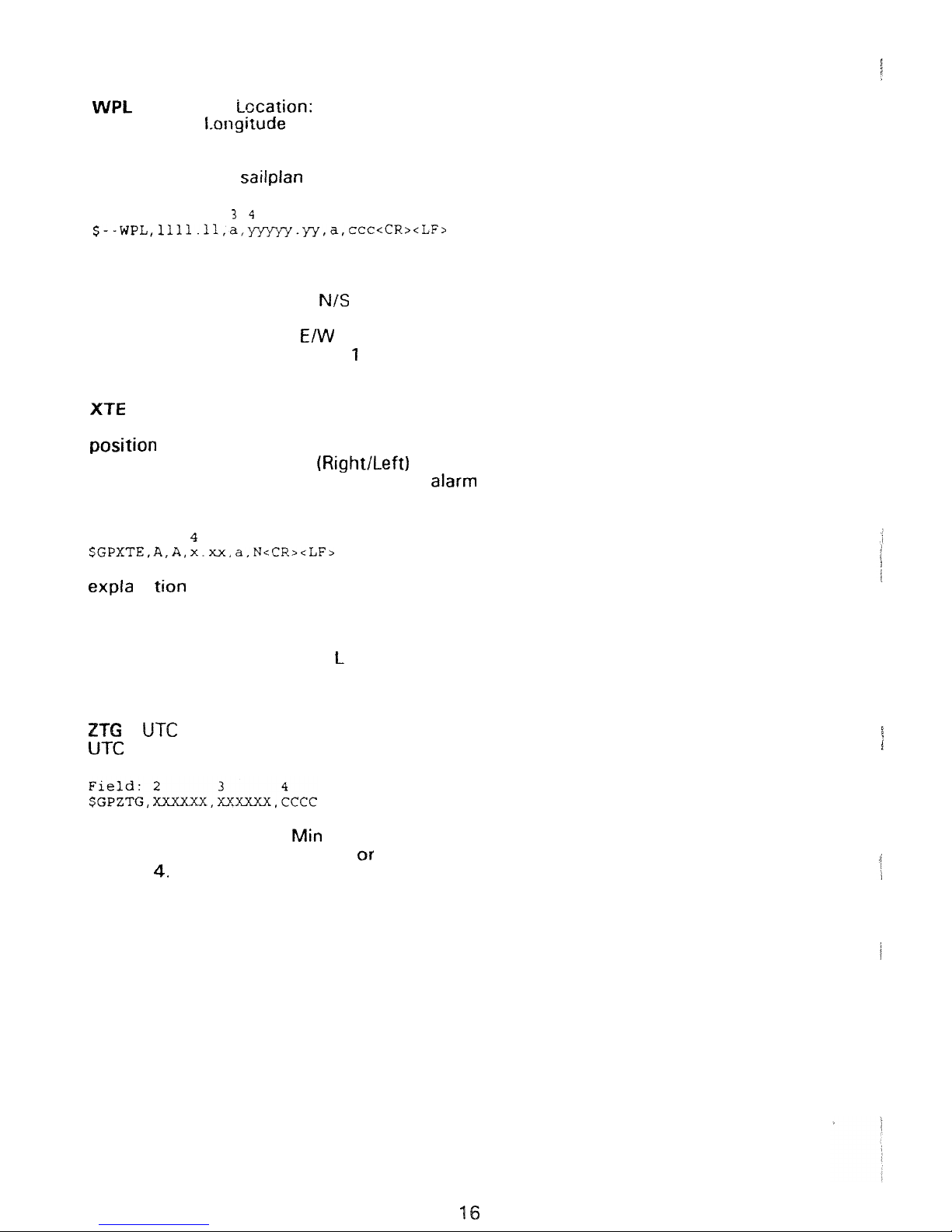
-
Waypoint Lccation:
Latitude and 1.ongitude
of
specified waypoint
The content
of
?his sentence
will
normally be the position
of
the next waypoint
in
the sailplan. When
following
the
RTE
sentence
the
positions of
all
the
waypoints
in
the sailpian
will
be transmitted.
field:
2
56
explanation:
2.
Waypoint
Latitude
3.
North
or
South,
4.
Waypoint longitude
5.
East or West,
6.
Waypoint identifier,
through
99
-
Cross-Track
Error,
Measured:
This
sentence contains navigation receiver update status, magnitude of the
error perpendicular to the intended track Dine as determined
by
the
sailplan,
and
the
direction (RightILeft) to steer to reduce the error. The sen
-
tence is transmitted when the autopilot alarm
is
set to
ON,
and when this alarm
is
not
in
alarm condition.
field:
2
3
56
na
:
2.
Status A or
V,
A
if
updating
is
OK,
V
if
updating is stopped
3.
not used, always
A
4.
Magnitude
of
XTE (cross-track-error)
5.
Direction to steer,
or
R
6.
XTE units, N for nautical miles
-
and
Time
To
Go
to
Waypoint
and predicted time to
go
to destination waypoint.
2.
UTC
in
Hour,
and Sec
3.
Estimated, Predicted
Elapsed Time
En
route
WPT
or Point
of
Interest.
Page 17
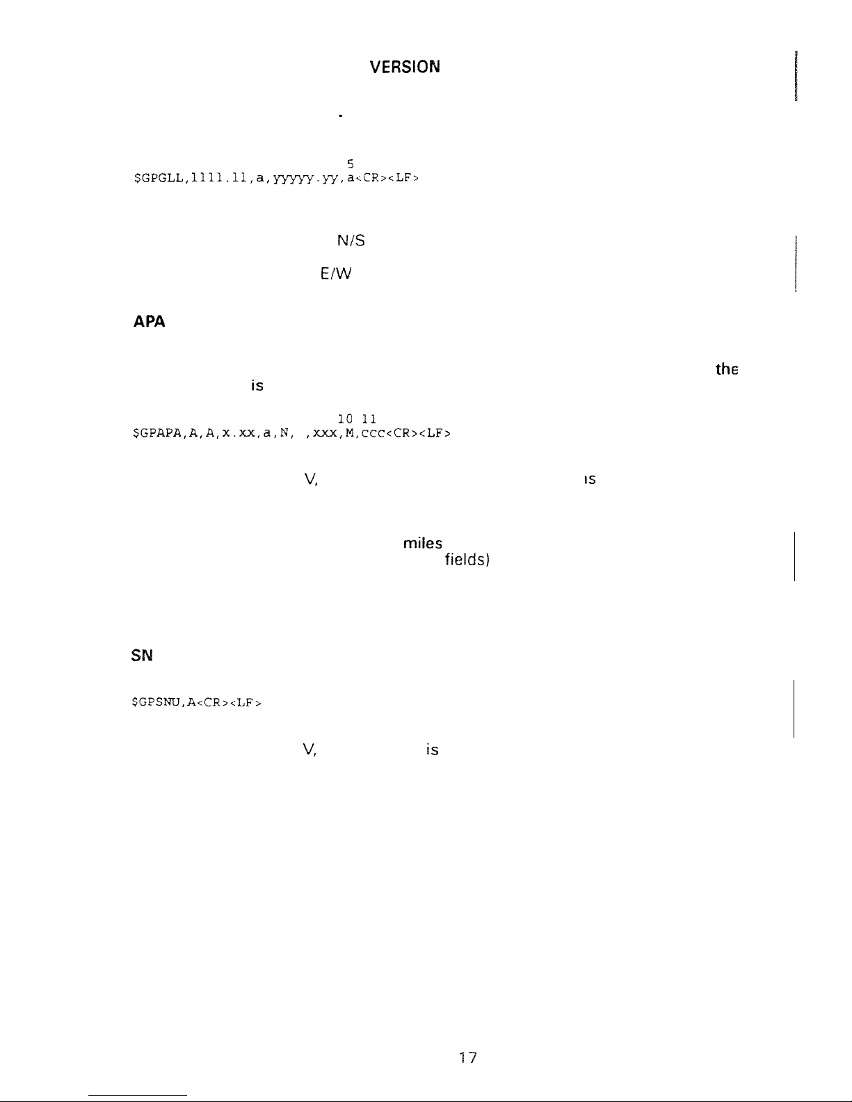
ACCORDING TO
NMEA
0183,
1.5
OF
DECEMBER
1987:
GLL
-
Geographic Position
Latitude and Longitude
Latitude and longitude of present vessel position.
field:
2
34
explanation:
2.
Latitude of present position
3.
North
or
South,
4.
Longitude
of
present position
5.
East
or
West,
-
Autopilot sentence "A":
Commonly used by autopilots, this sentence contains navigation receiver
update status, cross
-
track error and initial bearing from
origin
waypoint
to
the
next destination waypoint
in
the sailplan. The sentence is transmitted when
autopilot alarm
set to
ON,
and when this alarm
is
not
in
alarm condition.
field:
2
3
4
5
6
9
,
explanation:
2.
Status A or
A
if updating
I
S
OK, V if
updating
stopped
3.
not used, always
A
4.
Magnitude
of
XTE
(cross-track-error)
5.
Direction
to
steer, L or
R
6.
XTE
units,
N
for
nautical miles
7.
and
8. not
transmitted (empty
9.
Bearing origin
to
destination
10.
Magnetic,
M
1
1
.
Destination waypoint identifier
U
-
Receiver Update Status:
field:
2
explanation:
2.
Status A or
A
if updating
OK,
V
if updating is stopped
Page 18
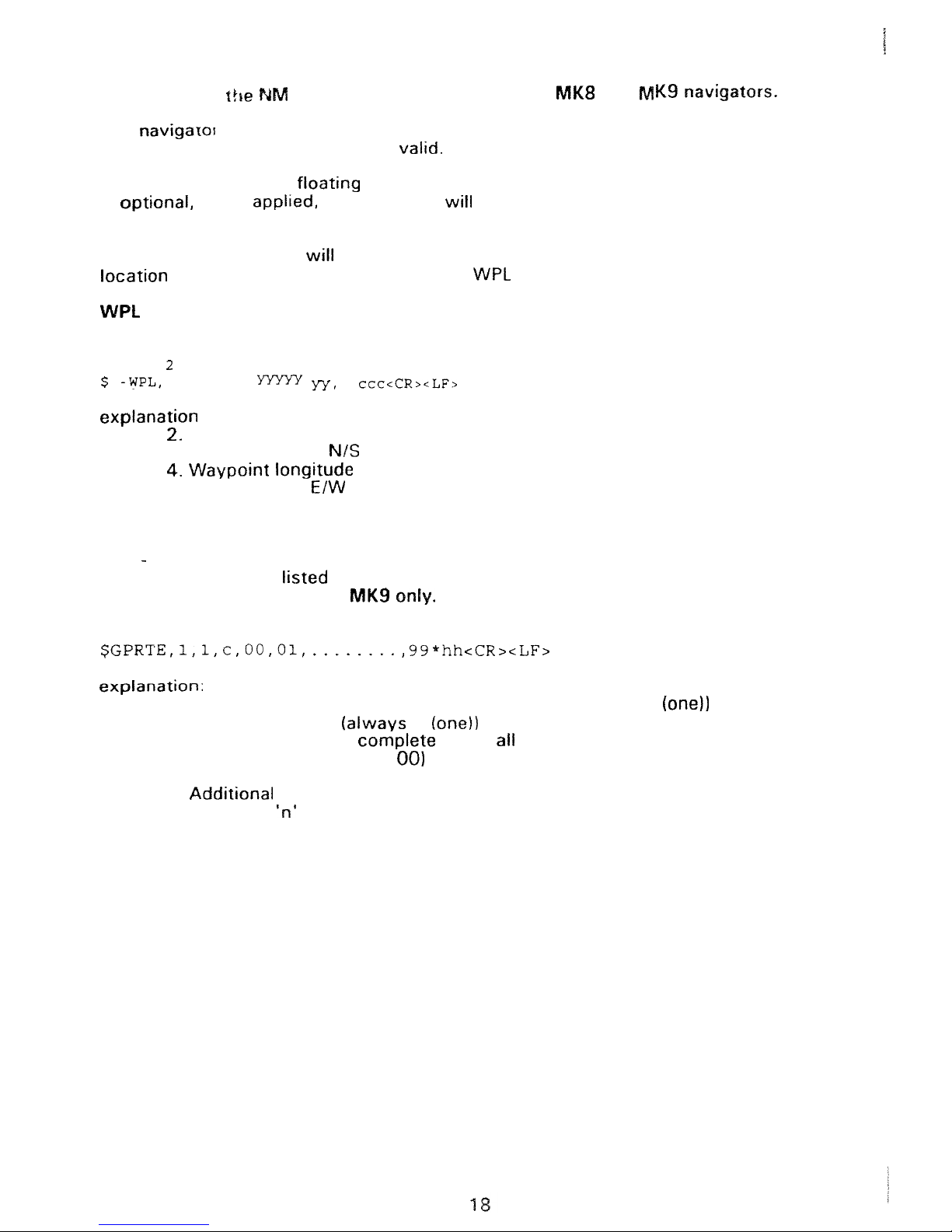
Description
of
The navigaIor
does
not use the
TALKER
identifier, and
any
pair of characters
within
the
NMEA
specification are valid.
EA
sentence
RECEIVED
by
the
and
The navigator accepts floating format
in
the
received numbers,
and
checksum
is
if
in
a
sentence
with
erroneous checksum.
The
received WPL data
overwrite the memory content
of
the
waypoint
is
contained
in
the
received
sentence.
-
Waypoint Location:
Latitude and longitude of specified waypoint
field:
34
56
-
111
1.11,
a.
.
a,
:
Waypoint Latitude
3.
North or South,
5.
East
or
West,
6.
Waypoint identifier, 1 through
99
RTE
Routes
Waypoint identifiers,
in
order
with
starting waypoint first.
This
sentence
is
received
by
field:
2
3
4
5
6
7
8
2.
Total
number
of
messages being transmitted
(always
1
3.
Message number (always
1
4.
Message mode: c
=
5.
Route identifier
(always
6.
Waypoint identifier
7.
8.
Waypoint
identifier
Page 19
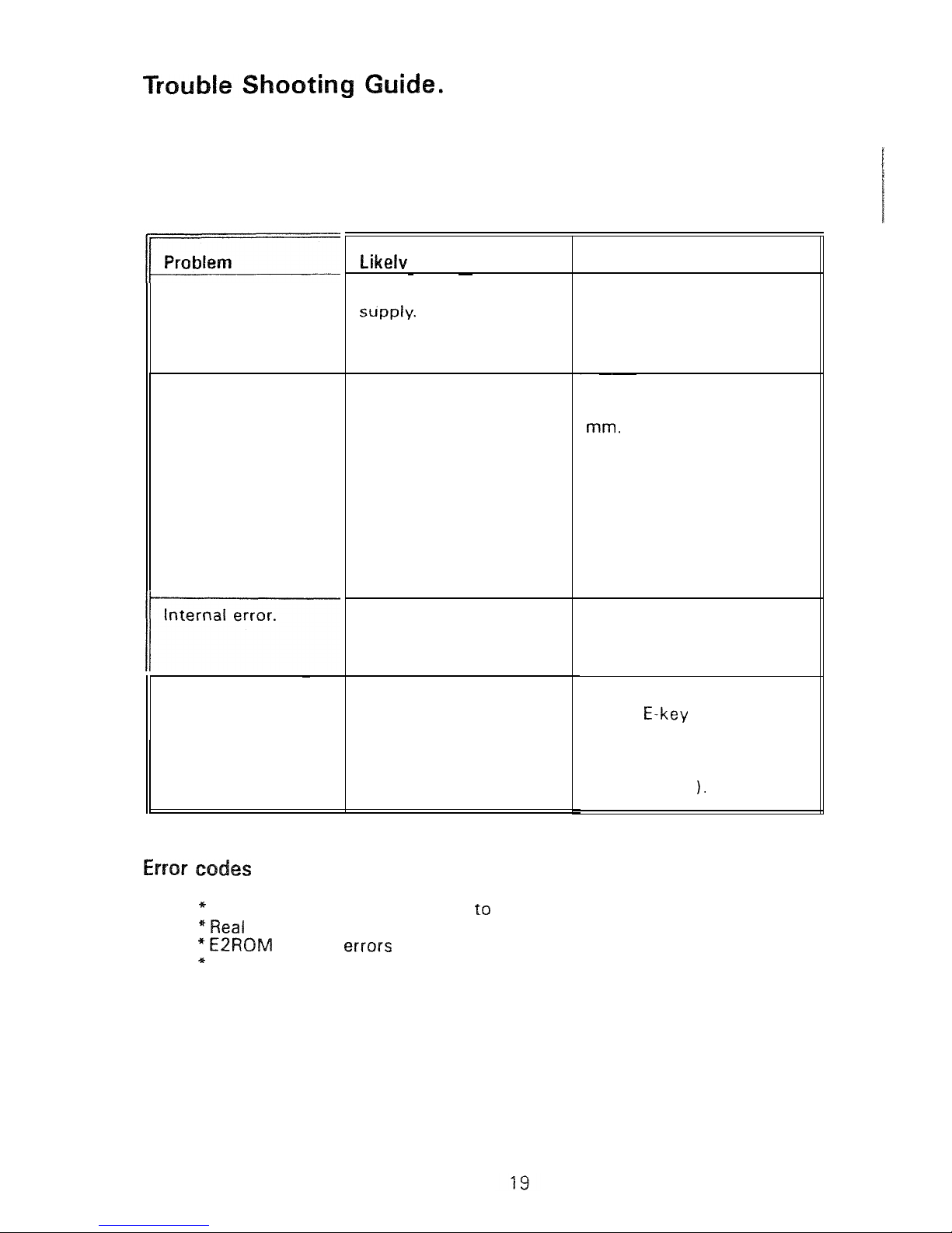
Please check
your
installation carefully before returning the navigator for serv
-
ice. A few hints are fisted
in
the table below. The navigator executes an online
check of essential functions. If
a
function is found erroneous, the navigator
gives an 'Internal Error' message every minute. To see the actual error code
you must run the self test program
in
the SETUP function..
No
response: (Blank
LCD
display and no
traffic
light).
Antenna open
alarm.
Antenna short
-
circuit
alarm.
Battery low alarm.
Antenna open
alarm.
Antenna short
-
circuit
alarm.
Battery low alarm.
No
update: (Red
blinking traffic light
for
more
than
10
minutes).
Cause
No
external power
Defect center core
at
antenna cable F connec
-
tor.
Defect antenna cable
installation.
Battery low.
Internal malfunction.
Position
or
time is
wrong.
Back
up
battery is flat.
Table
2
Baseband related
errors
100
109
time clock errors 201 to
204
related
303
Oscillator errors
400
to 410
Action
Check battery
vo
I
ta ge.
Check for
reverse
polarity.
Check wire installation.
Check if fuse is blown.
Check
that
core
of
F
connector
is
peeping out
1
See figure 1.
Check antenna cable for
hard
bends and
squeezing.
Check if inner core is bent.
Check battery voltage and
installation.
Return navigator
for
ser
vice. Please include error
coae found.
Make a power up reset:
(Press
is
switched on).
Exchange backup battery
(see page
21
If an
error
code
is
shown,
please note
it
on
a
piece
of
paper
and
enclose
it
with
the navigator when
you
send
it
in
for repair.
Page 20
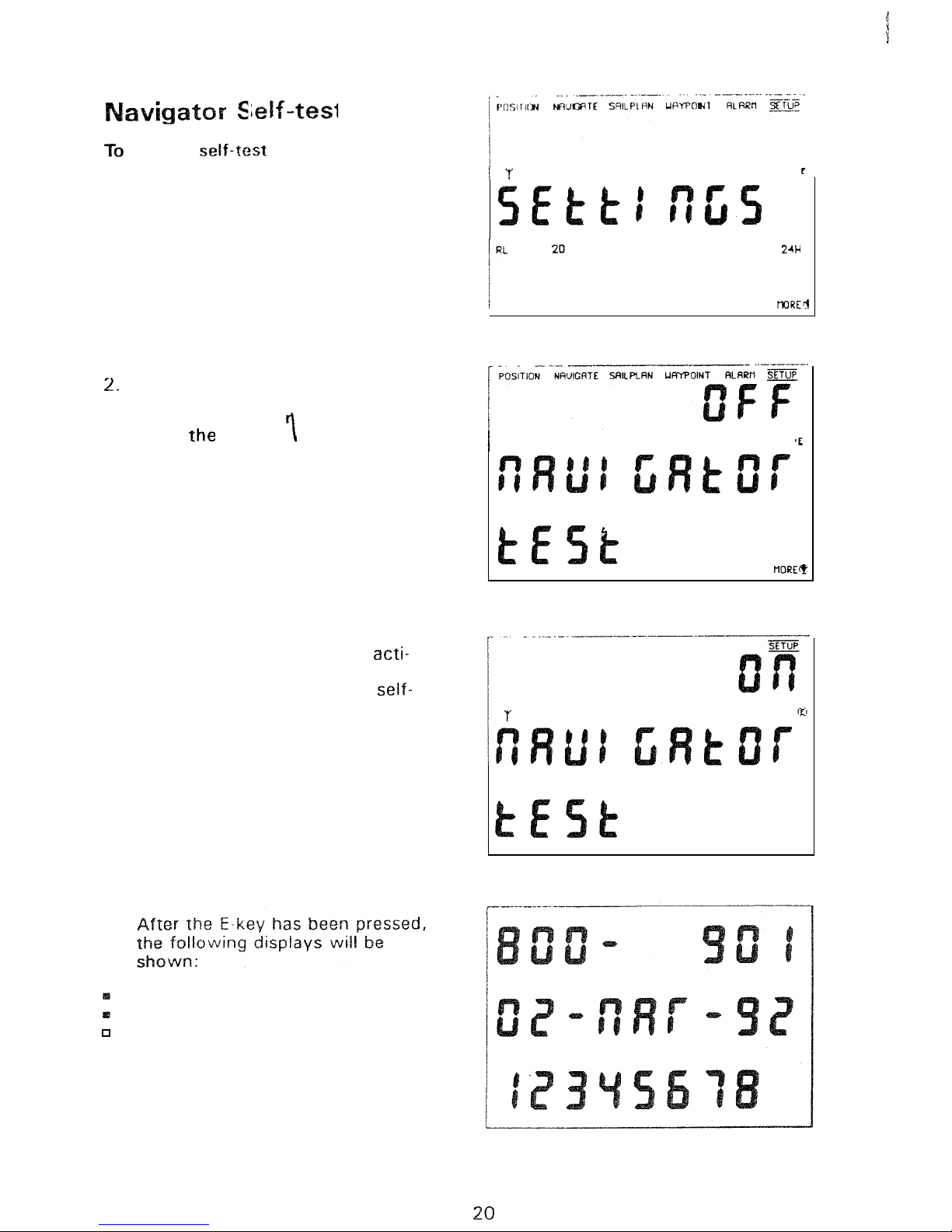
make
a
of
the
navigator:
1.
Select
SE
T
U
P.
Select
the
"
OFF
NAVIGATOR TEST
"
display,
by
pressing
the
up
o
down
key.
"
OFF
"
is
flashing.
3.
Press
E-key.
4.
5.
6.
Use
the
up
or
down
key
to acti-
vale the function
("ON").
Press
the
E-key
to start the
test.
Software release number.
Software release
date.
Serial
number.
BLEEP
Page 21
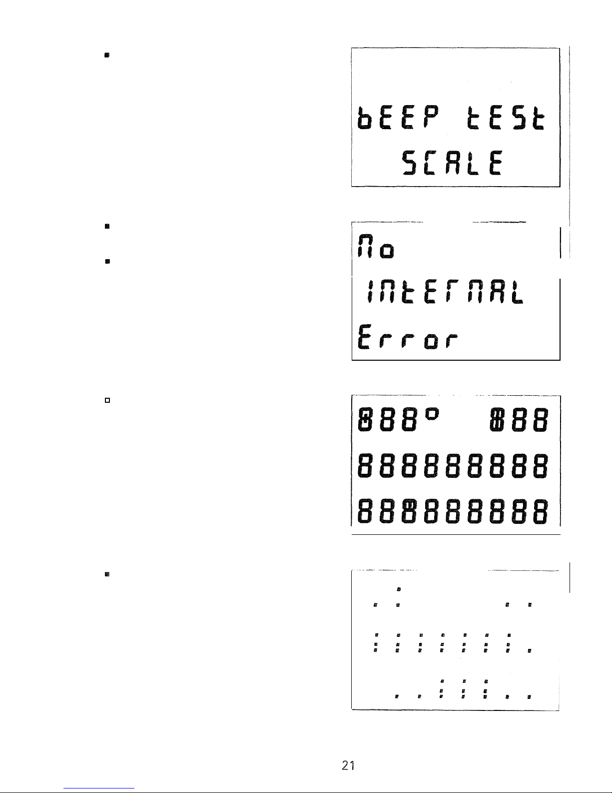
Bleep
test
will
sound
If
no
errors are found
this
will
be
displayed.
if
an
error
code
is
displayed,
note
the
number
and
contact your
service dealer.
-
1
.
Display
numeric
test.
Display
dot
test.
5
Page 22
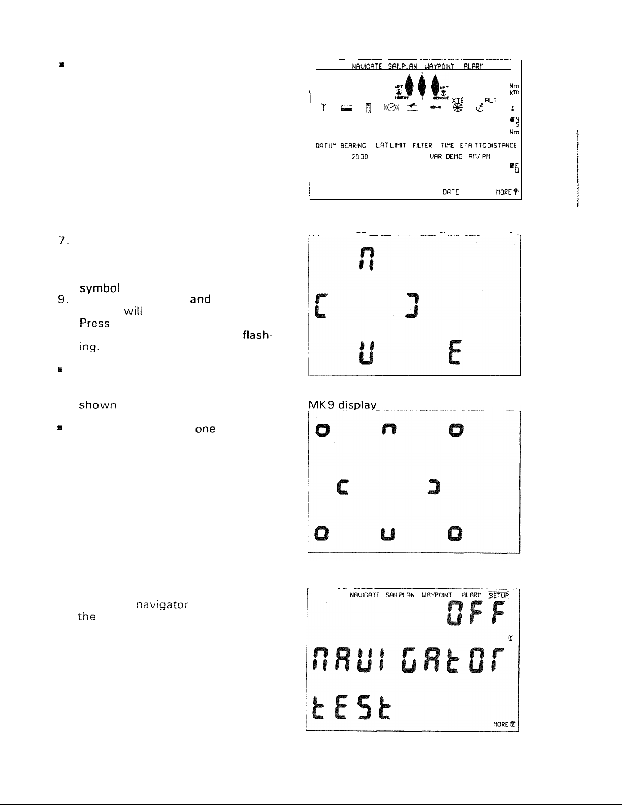
Display
symbol
test,.
.
-
-
-
-
-
-
/-POSITION
SETUP
kn
Hour
HOOP
UPT
OFF
SET
DRY
DRIFT
RL
GC
DCPS BLEEP
Z4H
kn
COG
LON
RCTUAL
OFF
Oh'
SOG
Key
board
test.
5
or
9
symbols
appear
on
the
dis
-
play
-
8.
Press
the
UP
key and the
UP
will
stop flashing.
Press
the
LEFT
key
the
LEFT
symbol
stop flashing.
10.
the
remaining
keys
and
the
rest
of
the
symbols
will
stop fiash-
If
all
symbols
have stopped flash
-
ing
the keyboard
is
ok, and the
display
will
change
to
the one
below.
If
you
can not make one
or
more
of
the symbols stop flashing by
pressing
the
corresponding
keys,
you
should contact your
service
dealer
reporting
the
key
board
error.
11.
When
the
has finished
self
test
it
returns
to
normal
mode.
MK8
display
.
.
.
.
POSITION
22
Page 23
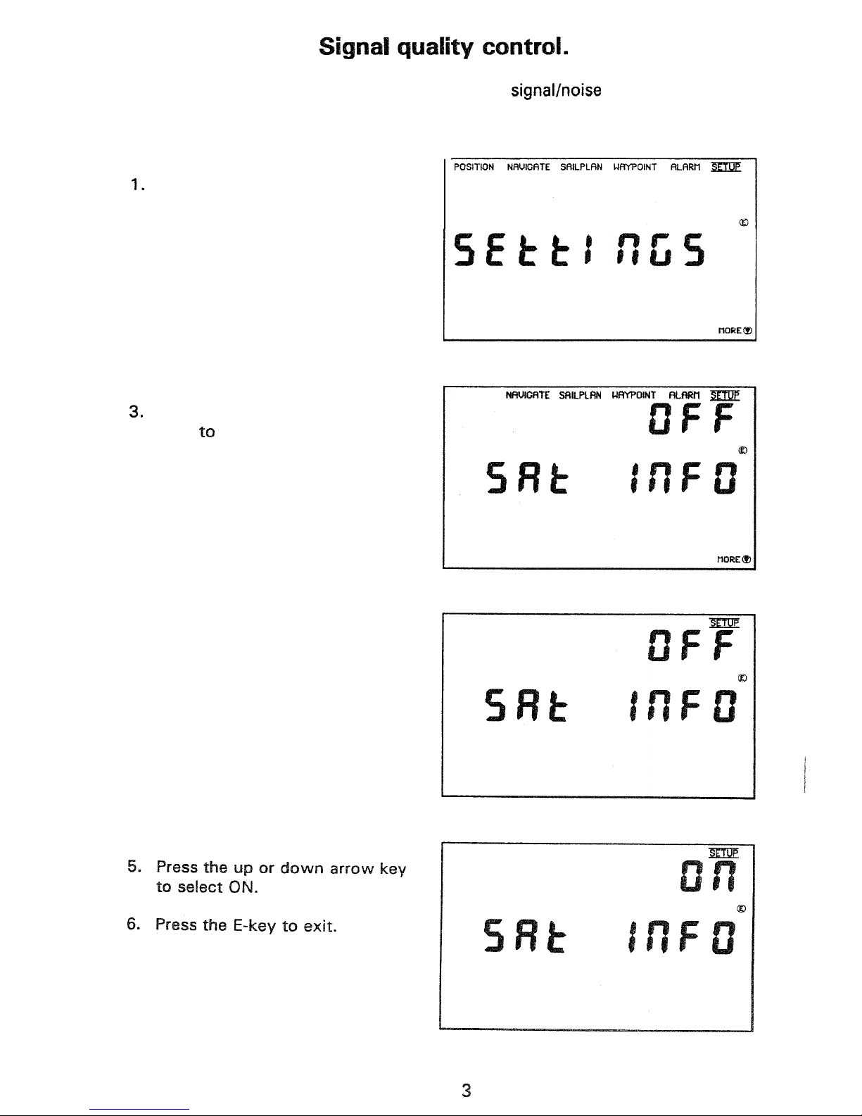
To
check
the signal quality,
you
can
monitor the signalhoise
ratio
in
POSITION.
The
following
example
describes
how:
If
SAT INFO
is
ON,
in
SETUP,
jump
to
point number
7.
2.
Select
SETUP.
Scroll up or
down
with the arrow
keys
select
the
SAT
INFO
display.
4.
Press the
E
-
key:
OFF
is
flashing.
POSITION NRUICATE SRtLPLRN UWOINT RLRRtl
BLEEP
POSITION NRUICATE SRlLPLRN URYPOINT
2
Page 24
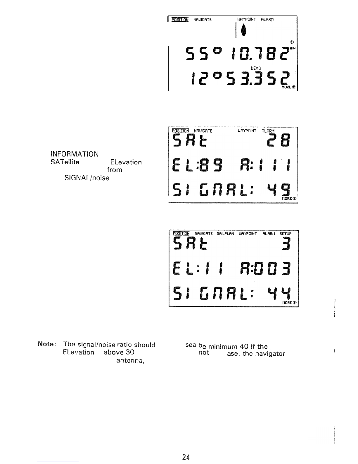
7.
Select
POSITION.
8.
Scroll up or down
with
the arrow
keys to select
the
SATELLITE
display.
number, ELevation
over
horizon,
Azimuth from true North
and
ratio.
SETUP
LRT
RE
LON
SAILPLRN
SETUP
I
9.
Press
the up
or
down arrow key
to
see the other displays, there
are
6,
one
for
each channel.
on
open
is
(degrees).
If
this
is
the
c
may have
a
bad
cable connection or a defective antenna.
Page 25
The navigator
is
almost maintenance free. There
is,
however, a few important
points to be noted.
Battery.
The internal real time clock and memory
that
keeps track of waypoints, alarm
limits etc
is
backed up by a
lithium
cell battery (Type
2032,
Expected
life time is
2
years.
ent
of
Backup Battery.
Be
sure to have the new battery
at
hand. Suppliers
will
typical
be
your
electronics dealer
or
a
radio
shop.
The battery
is
placed at the back of the navigator
unit
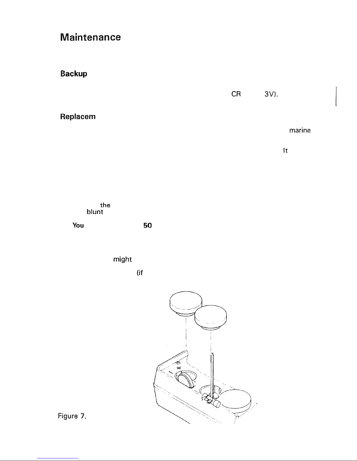
(see figure
7).
is an
advantage to have or just have had power on the
unit
(for 5 minutes), before
the battery
is
changed. This will give about three times
the
normal
50
seconds
to make the change:
1.
2.
3.
4.
5.
6.
7.
8.
9.
Dismount the navigator.
Dismount the
D-SUB
and
antenna cable
if
necessary to get to
the
back
of
the navigator.
Remove
lid
from the back of
the
navigator
using
a
coin
or
a
instrument.
Remove the old battery.
will
have at least
seconds
to insert the
new
battery without
loosing
the contents
of
the
memory.
Insert the new battery
checking the right
polarity.
Use a pair of plastic
tweezers, a rubber clove, a clear
thin
plastic back
or
a
similar tool to re
-
place the battery.
Do
not use your fingers directly
on
the battery. Grease
from fingers
reduce
the
lifetime of
the
battery severely.
Replace the rubber
lid.
Connect the cables
dismounted).
Remount the navigator.
Page 26

Replacement
of
Fuse.
The navigator has an internal fuse to protect
the
electronic from overvoltage
or
wrong polarity.
A
1.25
A
fast blow 05mm by 20mm must be used. Suppliers will typical be
your marine electronic dealer
or
a
radio shop.
The fuse is placed
at
the
back of the navigator unit (see figure
7).
You must
disconnect
the
power cable before installing the replacement fuse.
Also
please
check the
polarity
and
voltage
-
in
order to find
the
cause of the blown fuse
before reinstalling
the
navigator.
1.
2.
3.
4.
5.
7.
8.
9.
Dismount
the
navigator.
Dismount
the
D-SUB
and antenna cable.
Remove the fuse rubber lid from the back of
the
navigator using a coin
or
a
blunt instrument.
Remove
the
old fuse pulling
the
nylon strip.
Inspect
the
old fuse to test if
it
is blown. (If not check the power cable
in
-
stallation).
Place
the new fuse
in
the
fuse socket.
Be
sure to get
the
nylon strip under
-
neath
the fuse
in
order to be able to
remove
the fuse next time.
Replace the rubber
lid.
Connect the cables.
Remount
the
navigator.
Cleaning.
Use
a
fresh
clean
soft cloth
for
cleaning.
not
clean with alcohol
or
any other
solvent
as
it
will destroy
the
clarity
of
the
display window.
Salt
deposits on the antenna should be removed
at
regular intervals using clean
fresh water.
Page 27
Your navigator
is
an advanced piece of electronics. The many functions and
features are designed to fulfil most, if not
of the demands you may have
as
a
yachtsman.
We receive, however, many suggestions from a variety
of
users for new,
changed
or
extended features. This information combined
with
the
skill
of our
development engineers (of which most are keen yachtsmen)
gives
us the
possibility
of updating
the
software that controls the navigator.
The
navigator
products have always been on
the
forefront when
it
comes to yacht navigation. This
GPS
navigator
is
no
exception.
The navigator
is
designed
so
that the control software can be changed
or
updated without even opening the housing, When new software versions
become available, just
bring your navigator to
the
authorized dealer.
He
will
make
the
upgrade
in
a matter
of
minutes.
If
new software features (e.g. Differential
GPS
for
become available,
will
be
notified through the boating press
or
directly from your dealer.
The software updates will be available for
a
nominal
fee.
7
Page 28
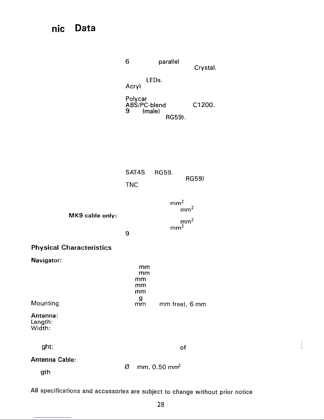
Tech
a
I
Technology
Navigator:
Receiver:
Display: Type:
Multiplexed:
Back
light:
Protection
:
Key board:
Text Foil:
Plastic enclosure:
Data Connector:
Antenna Connector
:
Antenna:
Type:
Ground plane:
Connector:
Material:
Antenna
Cable:
Type:
Connectors: Navigator end:
Antenna end:
Data
Cable:
Type:
Power:
NMEA
talker:
NMEA
listener:
MOB:
Connector:
Height:
Width:
Depth mounted:
Depth flush mounted:
Depth overall:
Weight:
stay length:
Depth mounted:
Depth overall:
We
i
Diameter:
ten
:
channels parallel continues tracking.
Transparent
STN
Liquid Crystal.
8:
1
Yellow LEDs.
7N
PMMA window.
Embossed membrane switch
(5
keys).
b
ona te.
pin
D-SUB.
F,
female (for
Patch
with
build
in
preamplifier.
Not needed.
Depending of type of antenna.
Depending of type of antenna.
or
F,
male twist on (for
male.
Joint pair
0.75
Shielded pair
0.10
Shielded pair
0.10
Joint pair
0.20
socket (female)
D-SUB.
127
222
40
to wall
23
to wall
75
680
45
(34
thread.
Depending of type
of
antenna.
Depending of type
of
antenna.
Depending
of
type of antenna.
Depending
of
type
of
antenna.
Depending
of
type
antenna.
6
solid core.
14
m
Page 29
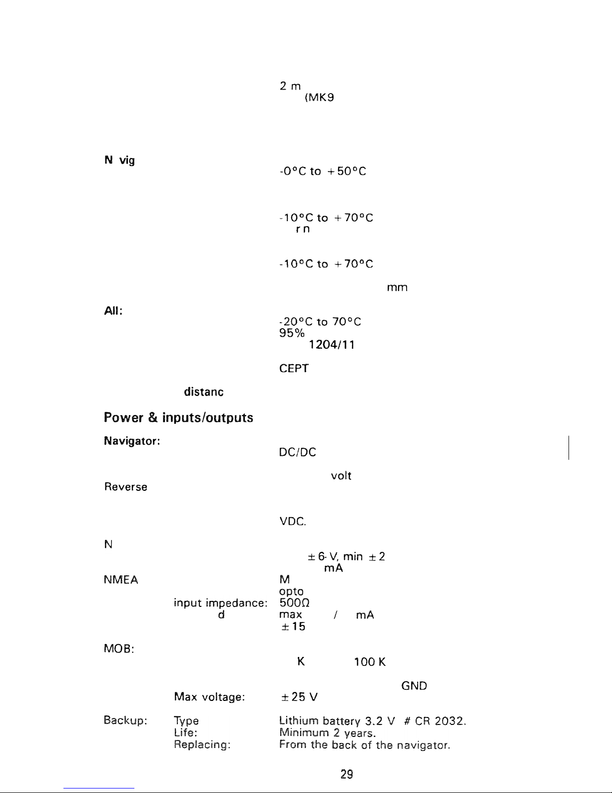
Data
Cable:
Length
:
Power:
NMEA:
MOB:
Environmental
a
a
to
r
:
Operating temperature range:
Ambient
conditions:
Antenna:
Operating temperature
range:
Ambient conditions:
Cables:
Operating
temperature
range:
Ambient conditions:
Bends:
Storage temperature
r
Relative humidity
:
Vibrations:
Compass
safe
nge:
Power: Type:
Supply voltage:
Overvoltage protection:
Isolation:
Consumption:
MEA
talker
(output):
voltage:
current:
listener
(input):
isolation:
th
res ho
I
:
max voltage:
Reference
:
input
impedance:
Activated:
6m
6
m
only)
Splash proof (when mounted correctly).
Ma
i
e, waterproof
.
Marine.
Minimum
radius
50
for antenna
cable.
MPT
FTZ
171
R47
I
EC
Recommended
0.5
m
TR
34-01
switch mode with galvanic separation.
Less than
5
W
(display back light on).
12
or
24
9.6
VDC
to
32
VDC.
At
0.7
V: Fuse.
At
40
V:
Fuse.
Supply voltage to
data
pins or shield:
Max
50
Meets NMEA
183
version
2.0
max
V
max
18
coupler.
2
V
2
V
eets NMEA
183
version
2.0
REF
GND.
50
Ohm
to
Ohm:
internal
pull
up
to
5
V.
Short-circuited
to
REF
(contact closure).
Page 30
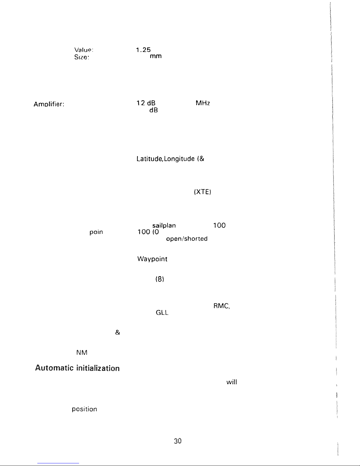
Battery change:
Time
for
battery
change
is
minimum
50
sec
-
onds without
loss
of data.
Fuse:
Amp
fast
blow.
Replacing:
0
5
by
20
mm.
From
the back
of
the navigator.
Antenna:
Power Consumption:
Supply voltage:
0.1 W supplied
by
the
navigator through the
antenna cable.
5.5
VDC
at
1575.42
Noise
figure:
2.5
Program
functions
Navigator:
Displays:
Position:
Navigate:
Sailplan:
Way
Alarms:
Altitude)
Time
Satellite status
Course Over Ground
Speed Over Ground
Cross
Track Error
Bearing to next waypoint
Distance to next waypoint
Time
To
GO
Estimated Time
of
Arrival
One
to
99)
Antenna open/shorted
Battery low voltage
Position
no update
Autopilot
Anchor
Time
Man Over
Board
(MOB)
NMEA
183
talker sentences:
Version
2.0:
Version
1.5:
APB, BWR, BWC,
RMB,
VTG
and
XTE.
APA,
and
SNU.
NMEA
183
listener sentences:
Version 2.0
1.5:
WPL.
Update:
Display:
Every second.
EA
sentences: Every two seconds.
The
navigator
has
an automatic position initialization which
always
result
in
the
correct position.
It
is
not possible to enter
an
estimated time
or
position
into the navigator. If the navigator
has
been moved more than a few hundred
nautical
miles
without tracking satellites, the navigator
will
start to search for
the correct
30
minutes.
!
Page 31
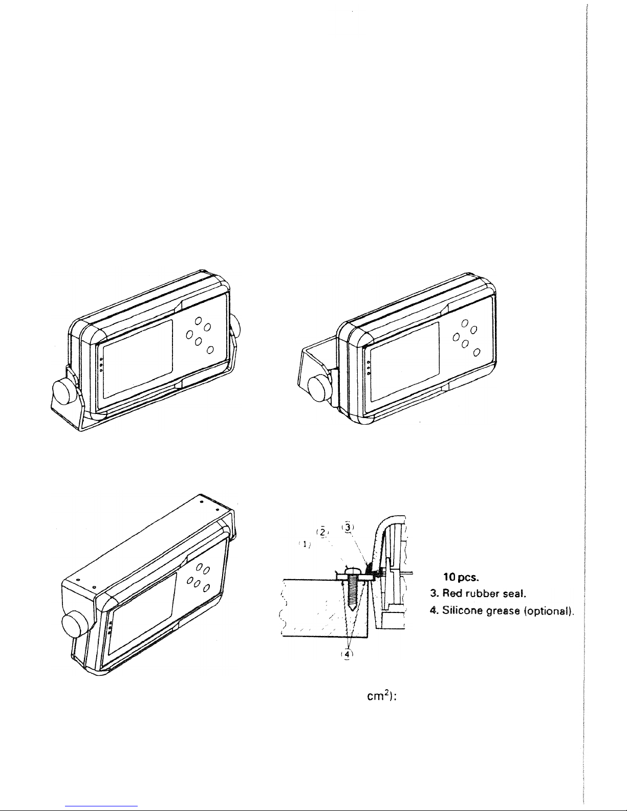
Equipment
Standard:
Navigator unit
Drilling template
Navigator mounting stays
and
nuts
Supply and interface cable
Backup battery cell
Users manual
Technical manual (this booklet)
Patch Antenna
Antenna cable
Antenna mounting bracket, screws and nuts
Antenna mounting instruction
Mounting Bracket for
below deck installation:
Part
No.
9525
200
70710
Optional
:
Flush Mounting
Kit
for above
or
below
deck mounting:
Part No.
9525
200
70700
1.
Flush
mounting
frame.
2.
screw.
Antenna for flush mounting on ground plane
(min.
area
800
Part
No.
9525
200
08980
31
Page 32
Australia
Coursemaster Autopilots
7
Smith Street
Chatswood,
N.S.W. 2067
Tel:
+61 29 417 7097
Fax:
+62
29
417 7557
Belgium
See Holland
Denmark
Leica
AP
Navigation
12A
DK-2730
Tel:
Fax:
+45
44 54
03
24
+45 44 94 43 96
OY
Hernesaarenranta
13
PL
326
FIN-001
51
Helsinki
7001
7780
Fax:
9
179 830
France
Furuno France S.A.
20
Avenue Edouard Herriot
F-92356
Le Plessis Robinson Cedex
Tel:
+33
46
29
94
29
Fax:
+33
1
40
94
08
45
Germany
NAVICO
DEUTCHLAND
43-45
D-24837
Schleswig
+49
4621 9613-0
Fax:
+49 4621 961 3-28
Great Britain
Comar Service Ltd.
Unit
3,
Medina Court
Arctic Road, Cowes
PO
31 7XD
Wight
+44
1983 282400
Fax:
+44 1983 280402
Se I ma
E
n
i
c
s
.
12-1
4
Gain. Tzelepi
GR-18531
Piraeus
Fax:
+30
14
95
Tlx:
241
892
+30 14
95
85-7
32
Holland
Sailtron
B.V.
5044
NL-3502
JA
Utrecht
Tel:
76 42
Tlx:
40 526
+31
Hong
Kong
Radio
Holland
Group
806
Join-In Hang Sing Centre
71
-
75
Container Port
Road
Kwai Chuna, N.T.
Tel:
422 39 007
05
898
Tlx:
50881
Grandagardi
18
IS-I
27
61
82
81
5
61
Ireland
See
Great
Britain
Messree MERCATORE srl.
P.O.
Box
36
Porto Turistico
6043
Chiavari (GE)
Tel:
+39 185 31 26
08
Fax:
+39 185 32 27 31
as
Langholmen
P.O.
Box
421
N-4370
Egersund
Tel:
+47
51
49 43
Fax:
+47
51
49 21
Soc. Corn. Crocker
Ca
Rua
Joao
2
-
P-1200
Lisboa
Tel:
13 88
01
41
Fax:
11
Page 33
South
Africa
Decca Contractors
S.A.
Pty.
Ltd.
1
2
Road
Ottery
7800,
Cape
Tlf:
+27
21
70
41
600
Fax:
+27
21
70
41 610
Spain
C.R.A.M.E.
SA
Severo
30
"
Barajas Park
"
E-28042
Madrid
Tel:
Fax:
+34
13
29
18
62
+34 13
29
30
46
Via
Augusta,
186
ES-0802
1
Barcelona
92
Fax:
+34
34
14
25 33
Sweden
Sportmanship Marin
AB
Bolsheden
I
nd
strivaeg
30
S-427
22
Ttf:
+46
31
93
94
00
Fax:
+46
31
91 32
31
Switzerland
Bucher & Walt
Route
De
8
+41
38
35 95
00
38
35
95
30
Turkey
Bolahenk
Sok.
No.
1
Taksim Istanbul
21
22
39
10
29
21
22
93
28
31
Fax:
21
22
43
61
25
33
Page 34
Terms
ALARM
Message
by
which the navigator signals the occurrence
of
an event. The alarm
is indicated
by
an
(or
icon) on the display.
ALMANAC
Library
of
coarse satellite orbital characteristics used to calculate satellite rise
times, set times, angles
of
elevation etc. Almanac data is valid
for
several
months.
ALTITUDE
The
height
of
the
navigator
over
mean
sea
(taking
into
account the ANTENNA
HEIGHT
as
stated
in
SETUP,
in
the User Manual).
ANTENNA HEIGHT
The height (over the water line)
in
which the antenna is installed.
AZIMUTH
In
satellite navigation, the angular distance measured on the horizon circle
in
a
in
the horizon to the satellite point
in
the horizon.
BEARING
The direction of one terrestrial point from another, expressed
as
angular dis
-
tance
from
north
clockwise through
360
.
COG
See COURSE
OVER
GROUND
COMFASS
HEADING
Compass
reading
before
correction
for
deviation
and
variation.
COURSE
The horizontal direction
in
which
a
vessel
is
steered
or
intended to be steered,
expressed
as
angular distance
from
north clockwise through
360.
(Strictly the
term
applies
to
direction
through
the
water,
not
the direction intended
to
be
made good over the ground). The course
is
often designated as
true,
or
compass
as
the reference direction
is
true, magnetic,
or
compass, respec-
ti
ve
I
COURSE LINE
A
line,
as
drawn on a chart, extending
in
the direction
of
a course
(rhumb
line).
COURSE
GROUND
Course
made good relative to the sea bed.
GROSS
TRACK
ERROR
The perpendicular distance from the vessel to the actual course line (track) as
defined
in
DATUM
The framework on
which
the coordinates used to define position on the earth's
surface
is
based.
In
the navigator, a datum shift relative to
84
is
defined
by
the following parameters:
and
F
A
Y,
Position of the reference ellipsoid origin in relation
to
the
Size and shape
of
a
reference ellipsoid.
satellite
ellipsoid
3
Page 35
EDIT
To
modify
existing
display data via
the
keyboard.
ELEVATION
ANGLE
The angle made by the line
-of-
sight range to the satellite and the horizontal
90
degrees when the satel
-
lite
is
overhead and
degrees when the satellite first appears on the horizon.
Satellites whose elevation angle is
less
than 3 degrees are not good candidates
for providing an accurate position (latitude and longitude) update.
ENTER
To store data
in
the memory of the navigator.
ETA
Estimated
Time
of Arrival. Calculated on basis
of
the
distance to
the
destination
and
the actual (present) speed.
FILTER
If the
GPS
signals are distorted
by
Selective Availability
the
COG and
readings
will
be unstable, especially at
low
speeds.
In
order to smoothen
the readings you can activate the FILTER TIME feature.
With
FILTER
TIME
set
to
0
(zero) minutes the navigator
will
have
the
dynamics
adjusted
to
yachting purposes.
With
S/A
active additional filtering
may
be
needed.
The averaging time
can
be increased to 1 through
minutes. The
optimal value depends on the characteristics
of
the
S/A
and your navigational
needs.
10
minutes may be a
good
starting point.
FUN
CTI
0
N
A specific operational capability of
the
navigator.
GLOBAL
SYSTEM,
GPS
The NAVSTAR Global Positioning System which consists of orbiting satellites,
a
network of ground control stations, and
positioning and navigation
equipment. When
operational, the system will have
21
plus
3
active spare
satellites
in
six
orbital planes about
20,200
kilometres above the earth.
GREAT CIRCLE
on
Great Circle. The advantage of Great Circle navigation
is
that
it
brings
you
the shortest
way
through the sailplan.
The
disadvantage is
that
a
Great Circle track may differ from the straight
rhumb
line
that
is
easily
drawn on a Mercator projected chart. Great Circle navigation
is
recommended
for
ocean voyages only. The advantage increases
by
higher latitude (north
or
south).
It
is
biggest on an east/west course
zero on
a
in
e and ~ongi~~~e~. Converted to metres it
is
theoretically
when
is
off.
TE
FA
Electronic circuits that permit the passage of
data
between different types
devices.
LATITUDE
of
a parallel plane
in
the earth's ellipsoid. The parallels define lati-
is
the e uator whose latitude is
degrees
and
to
Page 36
LEG
One of
stages
in
a sailplan.
LOCAL
ZONE
The time zcne (see TIME ZONE)
in
which the navigator is located
LOCAL TIME ZONE OFFSET
The number of hours by which the local time zone differs from Universal Time
Coordinated.
LONGITUDE
The circumference line of
a
meridian plane. The meridians define longitude. A
special case meridian is the Greenwich meridian whose longitude
is
degrees
and to which
all
other meridians are referenced.
MAGNETIC HEADING
Direction as sensed
by
the steering compass
in
relation to magnetic north.
MAGNETIC NORTH
Direction
in
the
plane
of
the observer's horizon toward the earth's north
magnetic pole.
MAGNETIC VARIATION
The angle
by
which magnetic north deviates
from
true
north at any given point
on
the
earth's surface.
MERCATOR CHART
A map developed by Mercator projection wherein the curved surface
of
the
earth's ellipsoid is projected onto
a
cylinder and the cylinder is "unwrap
form
a
flat representation
of
the ellipsoid (earth model).
NMEA
National Marine Electronics Association. The NMEA electronics interface speci
-
fications have been developed under the ouspices of the Association. The
NMEA
0
183
is
an internationally recognized specifications for interfacing
marine
electronics.
OFF
TRACK
See
CROSS
TRACK
ERROR
POSITION
UPDATE
The recalculation of position by analysis of satellite orbital data as referenced to
time.
RHUMB
LINE
The course of
a
vessel that keeps a constant direction drawn
as
line on
a
chart
or
globe and cutting
across
all
meridians at the same angle. A rhurnb line
is a straight line on a mercator chart.
on
rhumb
lines. See also GREAT CIRCLE NAVIGATION.
See
SE
LE CTI
V
I
LA
L
ITY
The sailplan
is a sequential list of waypoints describing the planned voyage. It
is
in
other words
the
"
active route" to follow.
Page 37
S
A
T
ELLIT
E
S
I
G
N
A
L
Transmitted
electromagnetic
energy
from
a
of
arrival
is
measured
by
the navigator to calculate the position
of
the navigator antenna.
SE
LE T I V
E
AVA I LAB
I
L
I
TY S /A
A
system whereby
the
accuracy
of
GPS
is reduced.
S/A
is controlled
by
the
U.S.
Department
of
Defense.
S/N (SIGNAL
-TO-
NOISE RATIO)
Quantitative relationship between the useful and non
-
useful part
of
the received
satellite signal. A high
S/N
indicates a good signal strength.
SOFTWARE
Values programmed and loaded into memory. The values represent a permanent
set
of
instructions
for
running the automatic functions (computations)
of
the
navigator.
SOG
-
SPEED
OVER
GROUND
Speed
in
relation to the sea bed.
STEERING
COMPASS
The compass used
for
navigation.
TIME
OFFSET
The number of hours
by
which the time zone differs from Universal Time
Coordinated
ZONE
of
the
24
longitudinal segments around
the
world, each generally
15
degrees and 1 hour wide.
In
some regions there are half-hour time zones.
TRUE HEADING
Direction
in
relation
to
true north. True heading
is
compass heading corrected
for
MAGNETIC VARIATION and deviation.
TRUE
NORTH
Direction along the meridian of the observer
to
the north
pole.
U N
I
VERSA
L
TI
E
0
0
D I N ATE D
time
corrected for polar motion of the earth and sea
-
sonal variation
in
the earth's rotation.
UPDATE
See
point,
the
planned
track
of
the vessel
position
coordi
-
nates nay be stored
the navigator. The? point position
is
the basis of
the
-to-
steer, estimated time of arrival
steering display
WORLD GEODETIC
SYSTEM
Worldwide
datums
72
and WGS
84)
used
for
satellite navigation
sys
-
tems. For
all
practical purposes the two datums
be considered identical
may
thus use the
offset figures from the chart
in
the
navigators
us
Offset datum
All
charts
will
be
converted
to
R.
37
Page 38
GPS
(the Global Positioning System) represents the state
of
the art
in
precise,
continuous, world wide satellite navigation.
The constellation
of
satellites
will
ultimately consist
of
24
operational satellites
(21
plus 3 operating spares). The
US
Department of Defense (DOD)
will
declare
the GPS constellation fully operational when
2
1
operational (Block
satellites
are
functioning
in
their assigned orbits. This is expected to occur
in
Users are cautioned that the system is under development, and signal availabili
-
ty and accuracy are subject to change
without
warning
at
the discretion of the
Therefore,
until
the system is declared Operational, any use of the system
is
at the user's own
risk.
GPS
will
provide
two
levels
of
service - a Standard Positioning Service (SPS)
and a Precise Positioning Service
(PPS).
SPS is a positioning service which
be
available to all
GPS
users on a con
-
tinuous, worldwide basis
with
no
direct charge.
SPS
will
be provided
on
the
GPS
frequency which contains a course acquisition
code and a naviga.
to
provide the capability to obtain horizontal
position accuracy within
meters
(95
percent probability) and
300
meters
99.99
percent probability. The GPS
frequency also contains a preci
-
sion (PI code, that is
not
part of the
SPS.
PPS is a highly
accuracy
military positioning service that
will
not
be
publicly
ava
i
la b I
e.
The
SPS
accuracy
is a result of a degradation
of
the basic
GPS
accuracy,
caused by
a
cryptographic technique called selective availability
Without
the typical horizontal accuracy is found
in
the range 15 to
30
meters
Unlike Decca
and
Loran-C navigators, the geographical accuracy and the posi
-
tion
repeatability are identical for 6PS navigators.
There
is at present no information
in
the GPS signals telling the civilian user
whether
S/A
is used
or
not.
However, if your boat is moored, and the navigator
shows a steady Course Over Ground and (low) Speed Over Ground, you may
expect
that
S/A
is
in
use.
3
Page 39
The
navigator
offers
a
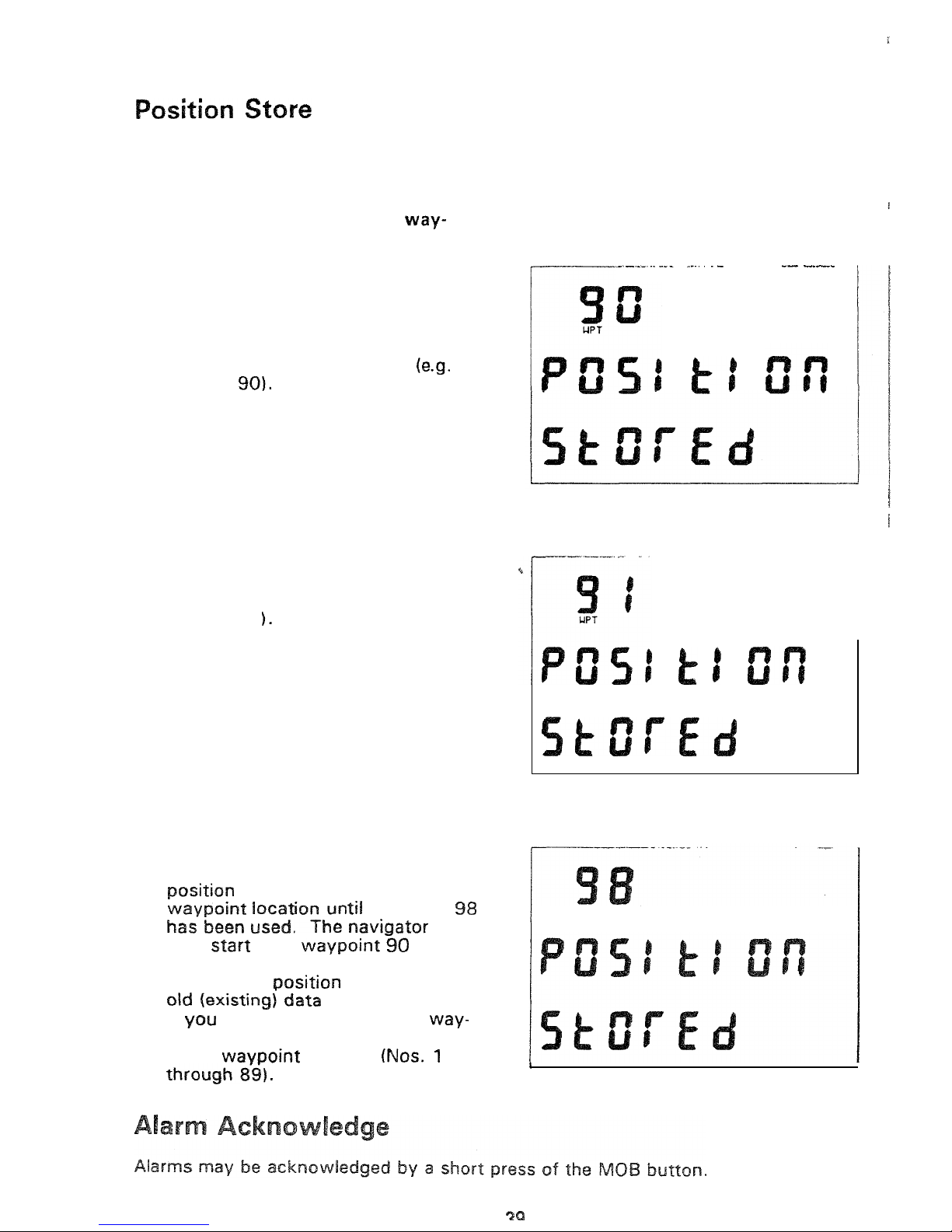
POSITION STORE (MARK)
feature. Waypoints
90
through
98
are reserved for
this
purpose.
Store the present position
as
a
point:
1.
Press the
MO5
button briefly (less
than
2
seconds). The latitude and
longitude of the present position
are now stored
in
the navigator.
The number of the waypoint will be
displayed
for
a few seconds
number
.
2.
The next time the button
is
pressed the new position
is
stored
in
the next
waypoint
location (here
number
9
1
3.
Each
time
the button
in
pressed
the
is
stored
in
the next
waypoint
UPT
then start with wa~~~in~
again.
4.
Each
time
a
is
stored.
the
are overwritten.
If
intend to keep the new
points,
they should be moved
to
a
'safe' wawoint location
I
Page 40
.
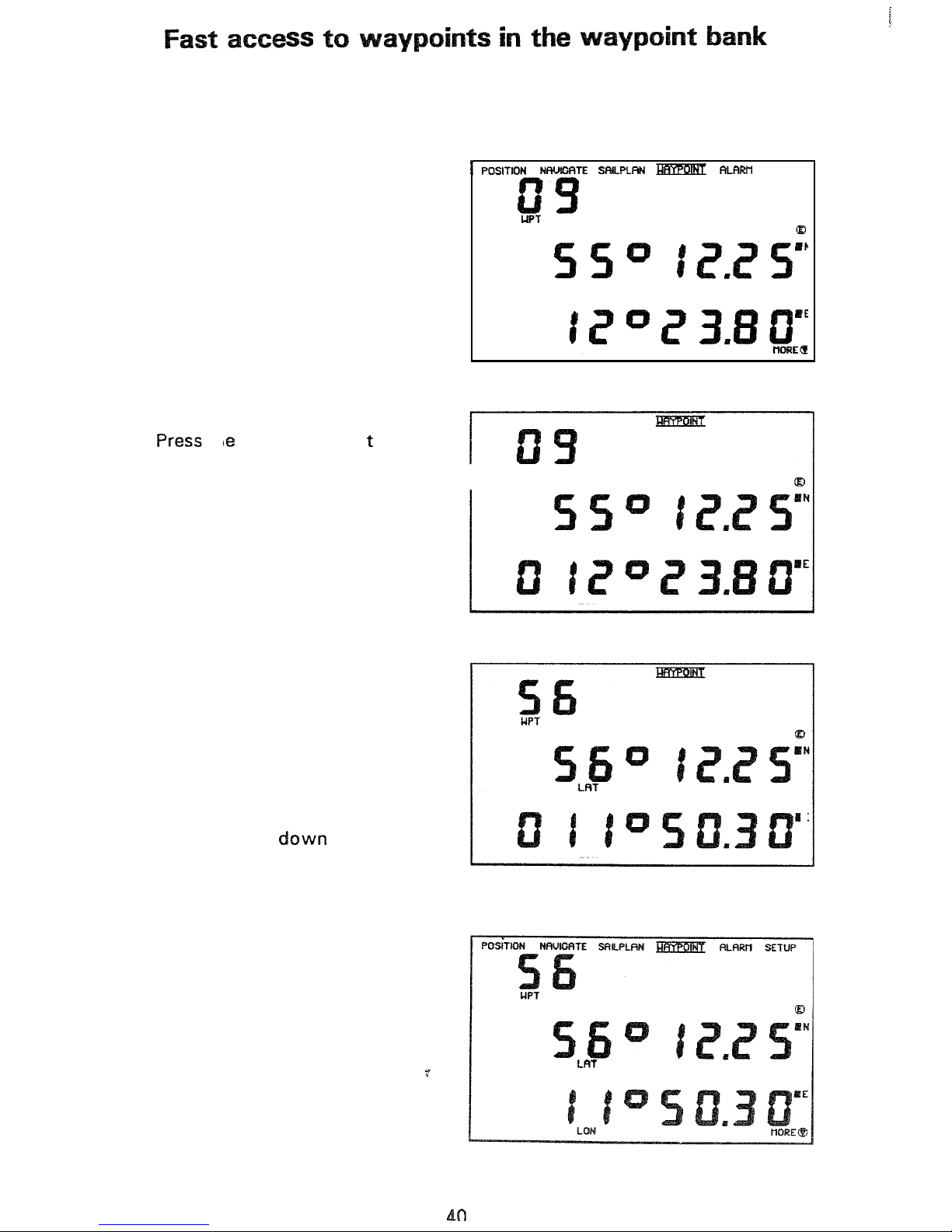
Instead
of
scrolling through the waypoint bank
(for
instance
from
WPT no
9
to
56)
you can choose
to
make
a
short
cut by editing
in
the waypoint number. The
following example describes how:
1.
2.
3.
4.
5.
6.
Select WAYPQINT.
th
E-key. The
fir
LAT
is
flashing.
digit
in
Press the left arrow key.
Now
the
last digit
in
WPT
is
flashing.
Use
the
up
or
down arrow key to
change
the
last
digit
of
the
waypoint number.
Press the left arrow key. The first
digit
in
WPT
is
flashing.
Use
the
up
or
change the
digit.
7.
Press
the
E-key
to
exit.
SETUP
LAT
LON
WPT
I
LAT
LON
E
LON
Page 41
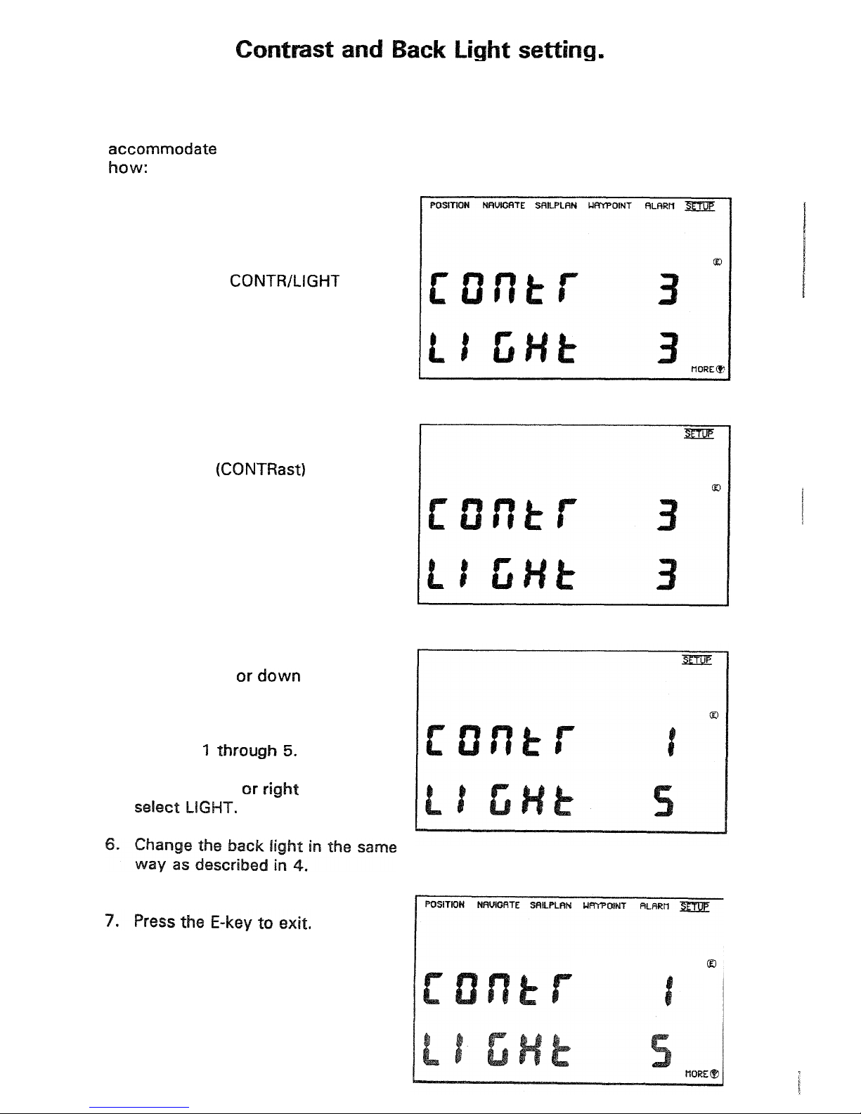
At
sunset and sunrise respectively, the
backlight
is
switched
ON
and
OFF
automatically. The contrast and back
light
of the display can be changed to
The
following example describes
1.
Select
SETUP.
2.
Scroll
up
or down
with
the arrow
keys
to
the CONTWLIGHT
display.
3.
Press
the E-key:
First digit
is
flashing.
4.
Press
the
up
key
and the
contrast of the display will
change.
The CONTRAST can be
set
on
a
scale
of
5.
Press
the
left
key
to
Page 42
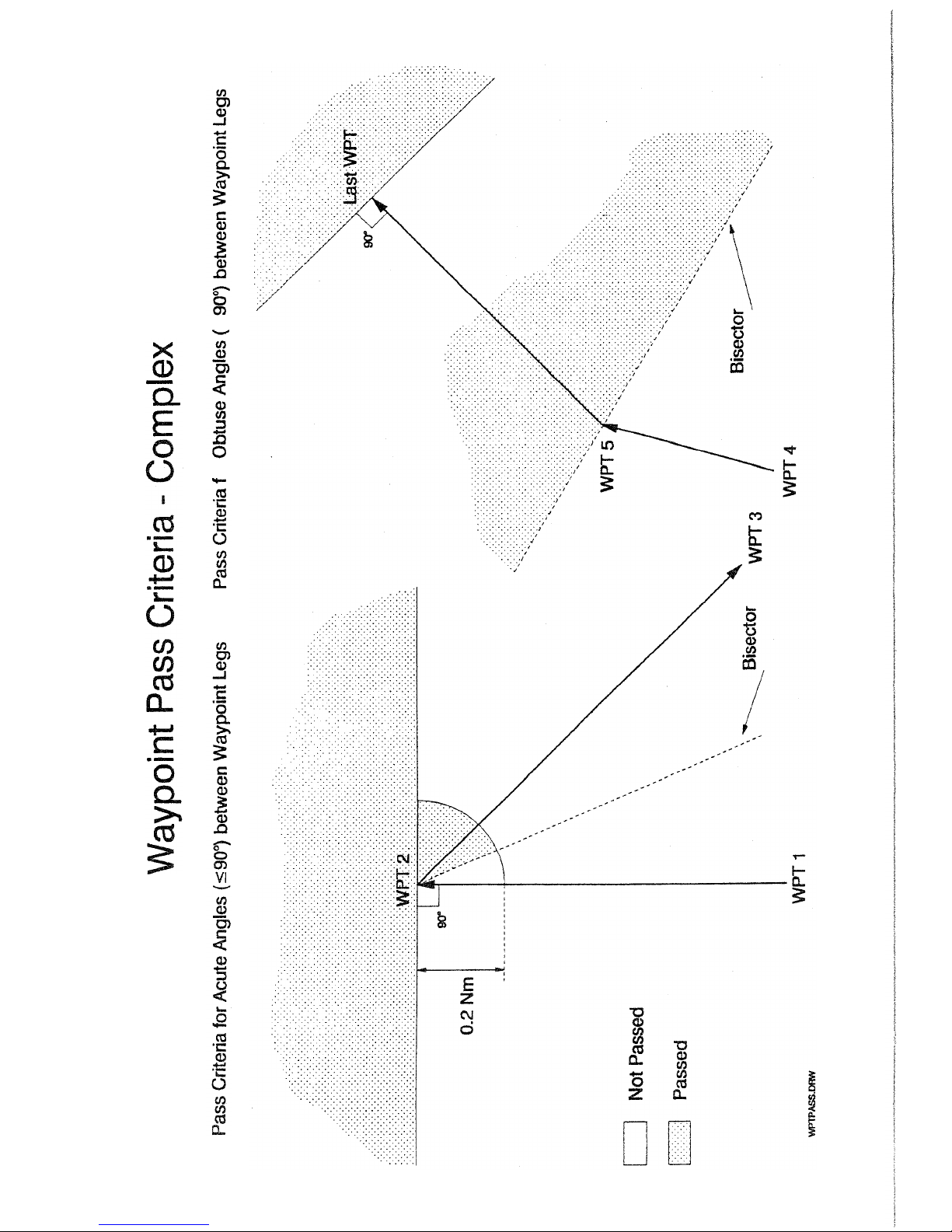
A
ti
42
Page 43
Page 44
Page 45
Page 46
oint
46
Page 47

Page 48

 Loading...