

Page 1

Operating Manual
Leica LPC
V1.0 English - 06/2010
Always keep this manual with the instrument.
Read carefully before working with the instrument.
/HLFD/3 &
Laser Printer for
Cassettes
Page 2

Page 3

NOTE
The information, numerical data, notes and value
judgments contained in this manual represent
the current state of scientific knowledge and
state-of-the-art technology as we understand it
following thorough investigation in this field.
We are under no obligation to update the present
manual periodically and on an ongoing basis according to the latest technical developments, nor
to provide our customers with additional copies,
updates etc. of this manual.
To the extent permitted in accordance with the
national legal system as applicable in each individual case, we shall not be held liable for erroneous statements, drawings, technical illustrations etc. contained in this manual. In particular,
no liability whatsoever is accepted for any financial loss or consequential damage caused by or
related to compliance with statements or other
information in this manual.
Statements, drawings, illustrations and other information regarding the contents or technical details
of the present manual are not to be considered
warranted characteristics of our products.
These are determined only by the contract provisions agreed between ourselves and our customers.
Leica reserves the right to change technical
specifications as well as manufacturing processes without prior notice. Only in this way is it possible to continuously improve the technology and
manufacturing techniques used in our products.
This document is protected under copyright
laws. Any copyrights of this document are retained by Leica Biosystems Nussloch GmbH.
Any reproduction of text and illustrations (or of
any parts thereof) by means of print, photocopy,
microfiche, web cam or other methods – including any electronic systems and media – requires
express prior permission in writing by Leica Biosystems Nussloch GmbH.
For the instrument serial number and year of
manufacture, please refer to the name plate at
the back of the instrument.
© Leica Biosystems Nussloch GmbH
Published by:
Leica Biosystems Nussloch GmbH
Heidelberger Str. 17 - 19
D-69226 Nussloch
Germany
Phone: +49 62 24 143-0
Fax: +49 62 24 143-268
Web: http://www.leica-microsystems.com
Leica LPC
3
Page 4

Table of Contents
1. Important Information ................................................................................................................ 5
2. Safety ............................................................................................................................................ 6
2.1 Safety notes ................................................................................................................................. 6
2.2 Warnings ...................................................................................................................................... 6
3. Instrument Components and Specifications....................................................................... 10
3.1 Overview – instrument components ...................................................................................... 10
3.2 Technical data ........................................................................................................................... 12
4. Instrument Setup ...................................................................................................................... 14
4.1 Unpacking instructions............................................................................................................. 14
4.2 Standard delivery ...................................................................................................................... 15
4.3 Assembling the filter unit ......................................................................................................... 16
4.4 Cassettes .................................................................................................................................... 19
4.5 Installation site requirements.................................................................................................. 20
4.6 Operating the printer................................................................................................................. 21
4.7 Loading the cassette magazines ............................................................................................ 23
4.8 Electrical connection ................................................................................................................ 24
5. Cleaning and Maintenance .................................................................................................... 25
5.1 Cleaning the laser lens ............................................................................................................. 25
5.2 Cleaning the filter inlet tubes ................................................................................................... 27
5.3 Cleaning the optical sensors ................................................................................................... 28
5.4 Changing the filters ................................................................................................................... 29
5.4.1 Replacing the prefilter .............................................................................................................. 30
5.4.2 Replacing the main filter .......................................................................................................... 32
5.5 Replacing fuses ......................................................................................................................... 35
6. Optional Accessories .............................................................................................................. 36
7. Appendix A – Laser Safety .....................................................................................................38
7.1 Laser hazard classes ................................................................................................................ 38
7.2 Inspection measures for laser classes .................................................................................. 40
7.3 Biological effects of laser beams ........................................................................................... 41
7.3.1 Eye injuries ................................................................................................................................. 41
7.3.2 Thermal injury ............................................................................................................................ 41
7.3.3 Skin injuries ................................................................................................................................ 42
4
Operating Manual V 1.0 – 06/2010
Page 5

1. Important Information
Symbols in the text and their meanings
Dangers,
warnings and cautions appear in a
gray box and are marked by a warning
triangle .
Notes,
i.e. important user information appear
in a gray box and are marked by an information symbol .
(5)
LOAD
Numbers in parentheses refer to item
numbers in illustrations.
Function keys to be pressed on the
touch screen are written in bold-print
capital letters.
Warning! Laser radiation
Invisible laser radiation, avoid exposing the eyes or skin to direct or scattered radiation.
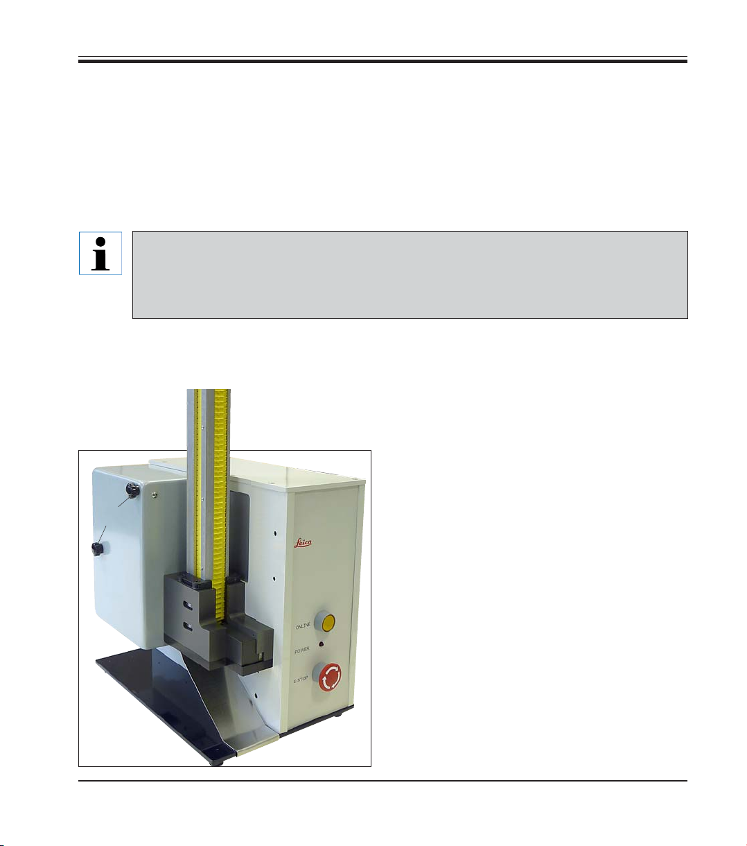
Intended use
The Leica LPC Laser Cassette Printer is used
solely to print identifying marks on LPC tissue
cassettes.
• The instrument has been designed for use in
pathology, histology, cytology, toxicology and
similar laboratories, and there only for laser
printing of LPC tissue cassettes.
• The LP C Laser Cassette Printer is used to create an individual identification mark in the form
of a high-resolution linear barcode, two-dimensional barcode and text on LPC cassettes
to prevent errors due to incorrectly identified
cassette blocks or specimen slides due to illegible handwriting.
• The instrument may be operated only according to the instructions contained in this manual.
Any other use of the instrument is considered
improper!
Qualification of personnel
• The Leica LPC Laser Cassette Printer may be
operated only by trained laboratory personnel.
• All laboratory personnel designated to operate the Leica instrument must read this Operating Manual carefully and must be familiar
with all technical features of the instrument
before attempting to operate it.
Leica LPC
Type
All information contained in this Operating Manual applies solely to the instrument type listed on
the cover page.
A nameplate indicating the instrument serial number is attached to the rear side of the instrument.
Fig. 1
5
Page 6

2. Safety
Be sure to comply with the safety instructions and warnings provided in this chapter.
Be sure to read these notes even if you are already familiar with the operation and use of other
Leica products.
2.1 Safety notes
This Operating Manual contains important instructions and information regarding the operational safety and maintenance of the instrument.
The Operating Manual is an important part of the
product, and must be read carefully prior to startup and use and must always be kept near the
instrument.
This instrument has been built and tested in accordance with the safety requirements for electrical equipment for measurement, control, and
laboratory use.
In order to maintain this condition and ensure
safe operation, the operator must observe all the
instructions and warnings contained in this instruction manual.
If additional requirements on accident
prevention and environmental protection
exist in the country of operation, this instruction manual must be supplemented
by appropriate instructions to ensure
compliance with such requirements.
The protective devices on both instrument and accessories may neither be removed nor modified. Only service personnel qualified by Leica may repair the instrument and access the instrument’s internal components.
For current information on applicable
standards, please refer to the instrument’s CE declaration and visit:
http://www.leica-microsystems.com
2.2 Warnings
The safety devices installed in this instrument by the manufacturer only constitute the basis for
accident prevention. Primarily responsible for accident-free operation is above all the institution
which owns the instrument and, in addition, the designated personnel who operates, services or
repairs the instrument.
To ensure trouble-free operation of the instrument, make sure to comply with the following instructions and warnings.
6
Operating Manual V 1.0 – 06/2010
Page 7

Warnings – Transport and installation
• Only connect the instrument to a grounded power socket. The protective effect may not be
eliminated by an extension cable without a protective grounding conductor.
• Do not operate in rooms with explosion hazard.
• Exposure to extreme temperature changes between storage and installation locations and
high air humidity may cause condensation inside the instrument. In this case, a two-hour
waiting period must be maintained before switching on the instrument. Failure to comply
with this may cause damage to the instrument.
• The Leica LPC Laser Cassette Printer and the corresponding software must be installed at
the customer's location by trained Leica employees and the instrument performance must be
checked.
• Contact your Leica representative before changing the location of the Leica LPC Laser Cassette Printer.
Hazards – Safety regulations on the instrument itself
• Safety instruction labels on the instrument marked with a warning triangle indicate that the
correct operating instructions (as described in this manual) must be followed when operating or replacing the instrument component bearing the label.
• Failure to adhere to these instructions may lead to accidents causing personal injury and/or
damage to the instrument or accessories.
2. Safety
Warnings – Working at the instrument
• The instrument may be operated by trained laboratory personnel only. It must only be operated for the purpose of its designated use and according to the instructions contained in this
manual.
• In the event of an emergency, switch off the power switch and unplug the instrument from
the power supply.
• Do not touch the ramp during operation. Risk of injury.
Leica LPC, Laser Cassette Printer
7
Page 8

2. Safety
Warnings – Cleaning and maintenance
• Before any maintenance, switch off the instrument and unplug it from power supply.
• Do not use alcohol, detergents containing alcohol (window cleaner!), abrasive cleaning
powders and/or solvents containing acetone or xylene for cleaning. Xylene or acetone will
damage the finished surfaces!
• Prevent liquids from entering the interior of the instrument while the instrument is being
cleaned or during operation.
Warnings – Chemical safety
• Never use the Leica LP C Laser Cassette Printer without ensuring that the filter unit is connected properly and is working. Otherwise, the instrument will malfunction and expel harmful dust particles.
Warnings – Optical/laser safety
• Invisible laser radiation, avoid exposing the eyes or skin to direct or scattered radiation
• CLASS 1 laser product using a CLASS 4 embedded laser (5 W, 10.57 – 10.63 µm)
• The laser beam is emitted by the lens, which is approximately 12.5 cm from the cassette in
printing position.
• Never attempt to operate the Leica LPC Laser Cassette Printer without the protective cover in
place.
• Never attempt to bypass any of the safety devices on the instrument.
• Never attempt to disassemble or repair the laser head. Contact the Leica service technician
in case of malfunctions.
• Each of the actions listed above can result in long-term eye or skin injury.
Warnings – Operational reliability
• Do not attempt to install the Leica LP C Laser Cassette Printer or to change the location. Otherwise, loss of data and/or malfunctions of the instrument may result. For cassette printer installation, contact a Leica representative.
• Do not attempt to install or reinstall the control software of the Leica LP C Laser Cassette
Printer. Otherwise, loss of data and/or malfunctions of the instrument may result. For software installation, contact your Leica representative.
8
Operating Manual V 1.0 – 06/2010
Page 9

• Never use the Leica LP C Laser Cassette Printer without ensuring that the filter unit is connected properly and is working. Doing so will cause the instrument to malfunction and expel
harmful dust particles.
• Always set up the Leica LP C on a stable, flat surface. Set up the LP C Laser Cassette Printer
so that the front and rear operating elements are easily accessible to the operator.
• Remember that minor color changes can occur in LPC cassettes if these are exposed to reagents that contain Picric acid, e.g. Bouin's fixative.
• Remember that text imprinted on Leica LP C cassettes can become illegible or be lost if these
are exposed for long periods to solutions that contain strong acids. Decalcification processes of tissue in Leica LPC cassettes that involve strong acids such as nitric acids, must be
checked by the users before implementation.
Warnings – Electrical safety
• Connect only the Filtronic GD80 filter unit provided with your LPC cassette to the exhaust
output (100-240 V, 50/60 Hz, 1 A max.).
• The supply cable of the Leica LP C must be connected to a grounded socket only. Ensure that
the Leica LPC Laser Cassette Printer is installed such that the power supply cable on the rear
side of the instrument can be removed easily.
• The supply cable of the Leica LPC must be connected to a grounded socket only. Use only
the power supply cable provided.
2. Safety
Warnings – Mechanical safety
• Never attempt to operate the Leica LP C Laser Cassette Printer without the protective cover
in place.
• Never attempt to bypass any of the safety devices on the instrument.
• In addition to the Class 4 Laser, the instrument contains moving machine parts that can injure
the user if the instructions above instructions are not observed (see Chap. 7 - Appendix A on
page 38).
Leica LPC, Laser Cassette Printer
9
Page 10

3. Instrument Components and Specifications
3.1 Overview – instrument components
2
33
3
33
1
7
4
5
1 - Basic instrument
2 - Monitor (optional)
3 - Cassette magazine
4 - Housing for the mirror device
of the laser
10
6
5 - Scanner (optional)
6 - Output chute for cassettes
7 - Online button
8 - Power LED
9 - Emergency stop button
Operating Manual V 1.0 – 06/2010
8
9
Fig. 2
Page 11

Rear panel and electrical connections
10
11
12
14 15
3. Instrument Components and Specifications
13
19
17
18
20
16
10 - Identification label
11 - Warning sticker: CLASS 1, laser product
12 - Serial connection
13 - No. for software upgrade
14 - USB port
15 - Network connection
16 - Main switch/toggle switch
21
Fig. 2
17 - Secondary fuses
18 - Power supply connection
19 - Key switch
20 - Power supply connection for filter unit
21 - Connecting port for hose on filter unit
Leica LPC
11
Page 12

3. Instrument Components and Specifications
3.2 Technical data
General
Approvals: The instrument-specific approval marks are located on the
rear side of the instrument next to the identification label.
Nominal voltage: 100 to 240 V +/- 10%
Nominal frequency: 50/60 Hz, 3 A
Classification: Pollution degree 2
Overvoltage installation category II
Laser classification: Class 1 sealed-tube laser,
5-watt output (see Appendix)
Secondary fuses: 2 x F 5 AL, 250 V
Operating temperature range: 5 °C to 40 °C
Relative humidity: 10 % to 80 %, non-condensing
Barcode compatibility: Code 128, Code 39, DataMatrix, PDF417
Connectivity to computer: USB, Ethernet, Serial
Dimensions and weight
Dimensions of basic instrument
Width x depth x height: 254 mm x 457.2 mm x 355.6 mm
Height (with magazine): 635 mm
Weight
Basic instrument: 19.5 kg
Filter unit approx. 13 kg
12
Operating Manual V 1.0 – 06/2010
Page 13

3. Instrument Components and Specifications
Dimensions of filter unit:
Width x depth x height: 210 mm x 490 mm x 460 mm
Electrical requirements: The filter unit is powered directly
by the cassette printer.
Filter compatibility: Use filters developed specially for this filter unit only. Contact a Leica employee
for ordering instructions.
Performance
Loading capacity: up to 70 cassettes/magazine
Printing speed
Printing batch jobs: 3-6 seconds (cassette to cassette)
Single-cassette printing: 8 s per cassette
depending on the type of printing
(positive or inverted)
Printing
Print resolution: 200 lines at 25.4 mm each
Printing medium: Leica LP C cassettes exclusively
PC system requirements
PC (100 % IBM-compatible computer)
Pentium 400 MHz
Windows XP, 7 *
50 MB of available hard drive space
64 MB RAM
1 serial port, USB or Ethernet (for connecting the printer)
Color monitor (800 x 600 or higher resolution recommended)
CD or DVD drive**
* Windows 95/98/Me/NT/2000/Vista are no longer supported by LabeLase® Producer. This does not necessarily mean that
the software will not run on these platforms, but we cannot guarantee that it will, nor do we offer technical support if not
everything works.
** If your computer does not have its own drive, copy the installation instructions to a USB stick, from which you can then
carry out the installation.
Leica LPC, Laser Cassette Printer
13
Page 14

4. Instrument Setup
4.1 Unpacking instructions
When the instrument arrives, check the tilt indicator (1) on the package. If the arrowhead is
blue, the shipment was transported laying flat, was tilted at too great an angle or fell over dur-
ing transport.
Note this on the shipping documents and check the shipment for possible damage. If it is evident that the shipment was damaged during transport, please make a claim to the carrier immediately.
1
2
3
2
Fig. 4a
Fig. 4
8
4
5
8
8
6
• Pry out the top eight clamps (2) -
as shown in the cutout (Fig. 4a).
• Remove the cover (3).
• To remove the side panel (4), remove the bottom two clamps
(5, Fig. 5, see cutout Fig. 4a).
• Carefully remove the printer (6),
the filter (7) and the accessory
cartons (8). Place the printer on a
stable laboratory bench.
Depending on the accessories ordered, the shipment may include an
empty carton used as dunnage to
guarantee safe transport.
7
14
Fig. 6Fig. 5
For safe transport of the instrument, we recommend keeping the original packaging and clamps.
Operating Manual V 1.0 – 06/2010
Page 15

4. Instrument Setup
4.2 Standard delivery
The Leica LPC standard delivery includes:
Box 1
Filter Unit-120 V or
Filter Unit-240 V
End pieces for filter outlet
Box 2
LP C - Laser Cassette Printer 120 V ............................................................................................ 14 0605 46656
or
LP C - Laser Cassette Printer 240 V ............................................................................................ 14 0605 46655
Cassette magazine
LP C printer key
Box 3
Housing with built-in prefilter (interchangeable) - incl. 1 prefilter bag for changing
10" hose (flexible, for connecting the filter unit and prefilter)
90° connecting pieces
Box 4
3 x 20 pcs. LP C tissue cassettes (samples)
10' PC power cable
Operating manual:
Hardware ....................................................................................................................................... 14 0605 80001
Software......................................................................................................................................... 14 0605 80002
DVD (LabeLase Producer CL-Software “incl. printer driver” + language files) ................. 14 0605 80003
10' / 1 1/8" gray tubing (with end piece)
1 set of cables: USA power cable, 110 V or
UK power cable
EU power cable, CEE 7/7
Network cable
USB cable
RS232 cable
3x 20 sample cassettes
Box 5 (can be ordered optionally, in the same crate as the printer)
Linear Magazine Kit, consisting of:............................................................................................ 14 0605 46657
4x magazine for cassettes and Magazine holder (for 4 magazines)
Leica LPC, Laser Cassette Printer
15
Page 16

4. Instrument Setup
4.3 Assembling the filter unit
Never operate the Leica LPC printer without the filter unit.
1a
Fig. 7
3, not
visible
4
• You need the filter unit (1a) and
accessory (2) cartons from the
transport crate.
• After unpacking, remove the four
knurled screws (3) and lift the lid (4)
2
housing as shown in Fig. 9 and pull the bottom
upwards briefly, then forwards and out in order to remove the inserted accessories (6). Be
sure to close the lid of the prefilter afterwards!
When reclosing, make sure
off of the lower part.
• Reach into the opening of the prefilter
that the metal tabs are
inserted correctly!
16
Fig. 8
1
Main filter
housing
3
Fig. 9
5
Fig. 9b
Fig. 9a
7
6
5 - The prefilter is
installed at the
factory
Operating Manual V 1.0 – 06/2010
Page 17

37
31
30
Fig. 10
4. Instrument Setup
• Hook the prefilter (37) - depending on your requirements, either at the left or right - into the
filter unit (30).
• Insert the clips (31, Fig. 11) back through the
cover and into the housing of the filter unit and
fasten the cover in place by inserting and tightening the four knurled screws (see cutout,
Fig. 11) - to do so, push each clip (31) back and
downwards slightly so that the knurled screw
can engage the thread.
Fig. 11
Leica LPC
31
17
Page 18

4. Instrument Setup
32
32
32
34
• Place connecting pieces (32) for the hoses on
the spouts at the correct angle, and seal off
the inlet you do not need using the plug (34)
provided.
The connecting pieces (32, 34) have to
be installed BEFORE the cover is attached to the main filter and before the
prefilter is attached to the side of the
filter housing. Failure to observe this
instruction can result in breakage of
the cover and the prefilter housing.
• Place the lid flat on a level surface and push
in the connecting pieces firmly.
36
37
38
35
Fig. 12
• The short black hose (36) connects the prefilter (37) to the main filter in the filter unit.
• The longer gray hose (38) connects the prefilter to the laser printer.
• Only now is the power cable (35) plugged into
the filter unit and connected to the LPC Laser
Printer (connection marked "20").
The filter unit is powered by the LP C
Cassette Printer.
18
Be absolutely sure not to kink the exhaust hose, as otherwise the suction
generated by the filter will be impaired.
Operating Manual V 1.0 – 06/2010
Page 19
4. Instrument Setup
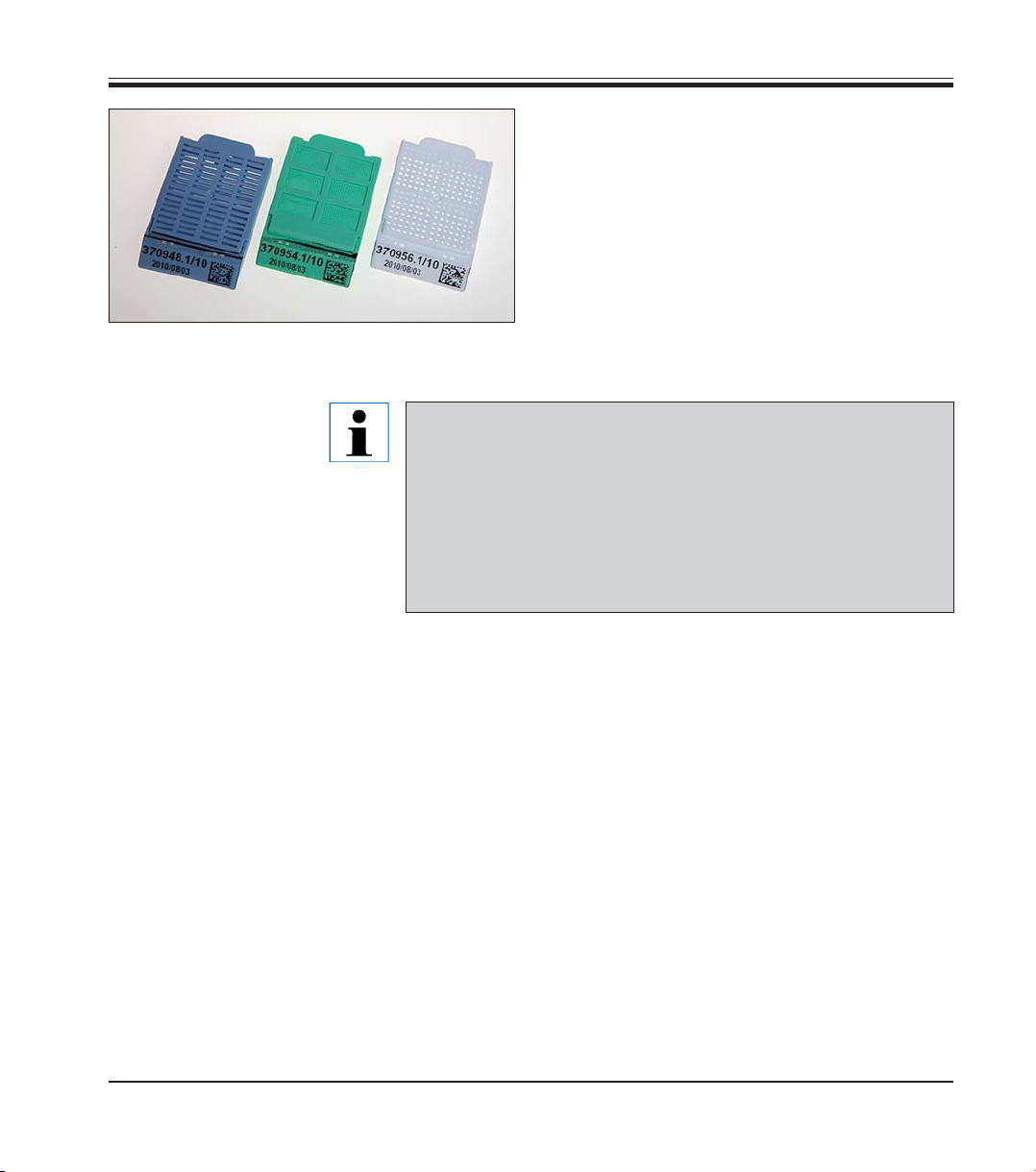
4.4 Cassettes
Only Leica LPC cassettes may be used for the
Leica LPC Laser Cassette Printer:
A - LPC tissue cassette
B - LPC fine-mesh tissue cassette
C - LP C biopsy cassette
BCA
Fig. 13
• Remember that minor color changes can occur in LP C cassettes
if these are exposed to reagents that contain Picric acid, e.g.
Bouin's fixative.
• Remember that text imprinted on Leica LPC cassettes can become
illegible or be lost if these are exposed for long periods to solutions that contain strong acids. Decalcification processes of tissue in Leica LPC cassettes that involve strong acids, such as nitric
acids, must be checked by the users before implementation.
The cassettes are offered in various colors - for
more information, refer to Chap. 6, Optional
Accessories.
Leica LPC
19
Page 20

4. Instrument Setup
4.5 Installation site requirements
The installation site must be well-ventilated.
Never operate the instrument in rooms with explosion hazard.
• The printer needs an installation area of approx. 260 x 460 mm and the filter unit needs an additional installation area of approx. 470 x 490mm.
Additional space is required for the PC containing the control software.
• Stable laboratory bench and practically vibration-free floor.
• Room temperature consistently between +5°C and +40 °C.
• Relative air humidity maximum 80 %, non-condensing.
• Avoid vibrations, bright direct light and strong temperature fluctuations.
• The AC socket used for the power supply must be close to the laser
printer and easily accessible.
• The laser printer is intended for use in enclosed rooms only and may be
used at elevations up to 2000 m only.
20
Operating Manual V 1.0 – 06/2010
Page 21

4. Instrument Setup
4.6 Operating the printer
3
3a
4
22
23
16
19
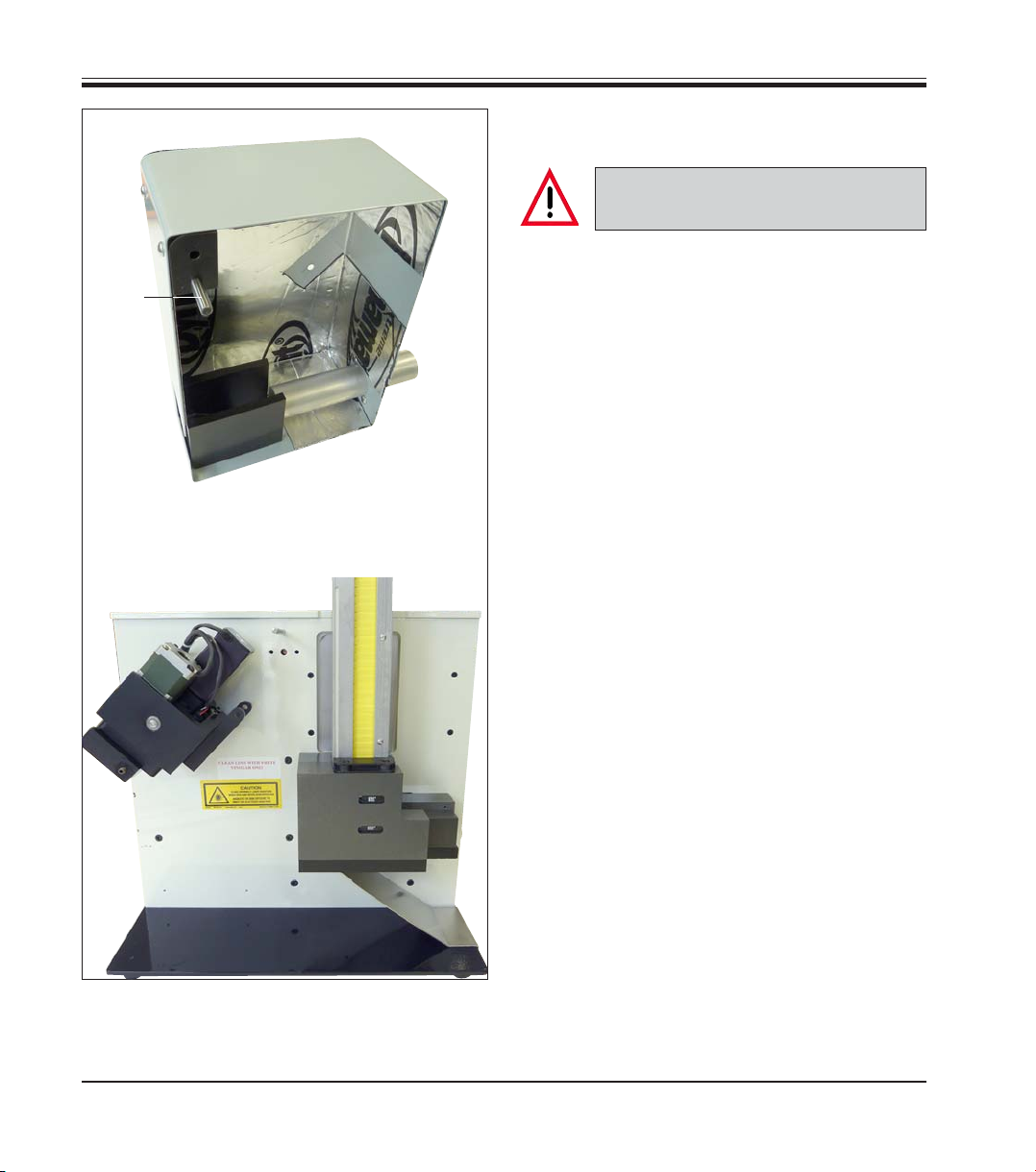
The Cassette Printer contains a housing for the
mirror device of the laser (4) and 1 cassette magazine (3) that can hold 70 tissue cassettes (3a).
Located directly below the cassette magazine,
the gripper mechanism (22) pushes the cassettes
out of the magazine, transports them to the marking position and then conveys them downwards
through the output opening of the cassette chute
(23). The cassette magazine (3) can be removed
easily to replace the cassette guide or the dye by
simply lifting it straight.
(Optionally, additional magazines for easy replacement of the cassette guide or dye are available.)
The front side has an emergency stop button (9),
7
8
9
Fig. 14
the power indicator (red LED, 8) and an online
button (7). The online button will light up when
the Cassette Printer is online.
Safety Interlocks
To prevent accidental exposure to harmful laser
radiation, the LPC Laser Cassette Printer incorporates several types of safety features:
1. Mechanical switches
• These switches are located at the front, rear
and in the housing cover of the Cassette Printer. They will remove power supplied to the
Cassette Printer.
• E-STOP emergency stop push button (9) –
large and red, easily accessible,
• Key switch (19) for locking/shutdown – for operation, turn it to the right stop and leave it
there.
• On/off main toggle switch (16).
Fig. 15
Leica LPC
21
Page 22
4. Instrument Setup
24
11 - Safety interlock pin
12 - Intake slot for safety
interlock pin
25
• Safety Interlock (24/25) in the main cover.
If the Safety Interlock operates, the
user must:
• Immediately investigate the reason for the interlock.
• Check the housing cover for damage before
starting up the Cassette Printer.
• If damage is found or the instrument does not
work, stop using the Cassette Printer and
contact the Leica service technician or Sales
Consultant to have the problem remedied.
2. Mechanical design
The beam path from laser tube to final pass
through lens is entirely enclosed in a metal
shield, with suitable material that will absorb
the heat produced by the beam emitting from
the laser.
3. Password security access
The software requires the user to enter an
access password to change the layout of the
cassettes of the operating parameters of the
Cassette Printer itself, including the laser cycle. The password-protected areas of the Cassette Printer software may be accessed only
after consultation with the Leica service technician.
The features and precautions described above
are designed with the safety of the user in mind.
Should you have any questions or suggestions
please contact Leica directly.
22
Fig. 16
Operating Manual V 1.0 – 06/2010
Page 23
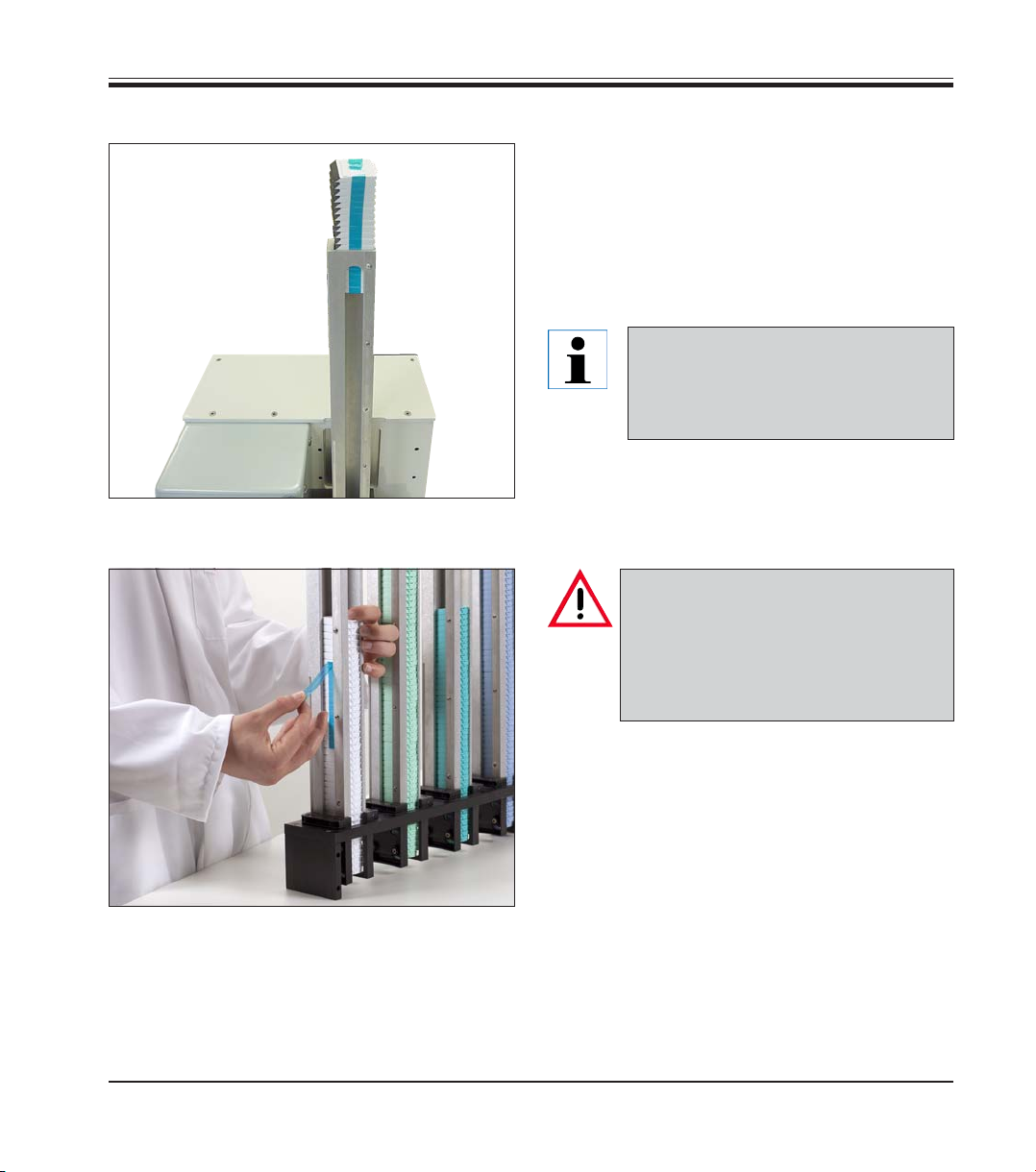
4.7 Loading the cassette magazines
Coated surface
4. Instrument Setup
The correct cassette color and type must be selected by the user. The magazines must be manually loaded with cassettes of the type and color
the user intends to print. The Cassette Printer is
not capable of identifying what type and color
cassettes are placed in the magazines or what
magazine is loaded into the machine.
Be absolutely certain to insert the cassettes correctly - the coated side
(black) points toward the closed side
of the magazine!
Fig. 17
Leica LPC
Magazine
opening
Band tab
Fig. 18, Multiple magazine holder,
optional
Use only LPC Cassettes for the Cassette Printer. The LPC Cassettes are
coated with a black coating on its
front surface. Without this coating the
Cassette Printer will not be able to
print on the cassette.
To load a Cassette Magazine:
• Insert the cassettes with the adhesive tape
pointing towards the opening on the side of
the magazine and the coated side of the cassettes pointing towards the closed side of the
magazine.
• Pull off the adhesive tape while holding up the
cassettes using your hand.
• Guide the cassettes in the magazine down-
wards after the tape has been removed.
23
Page 24
4. Instrument Setup
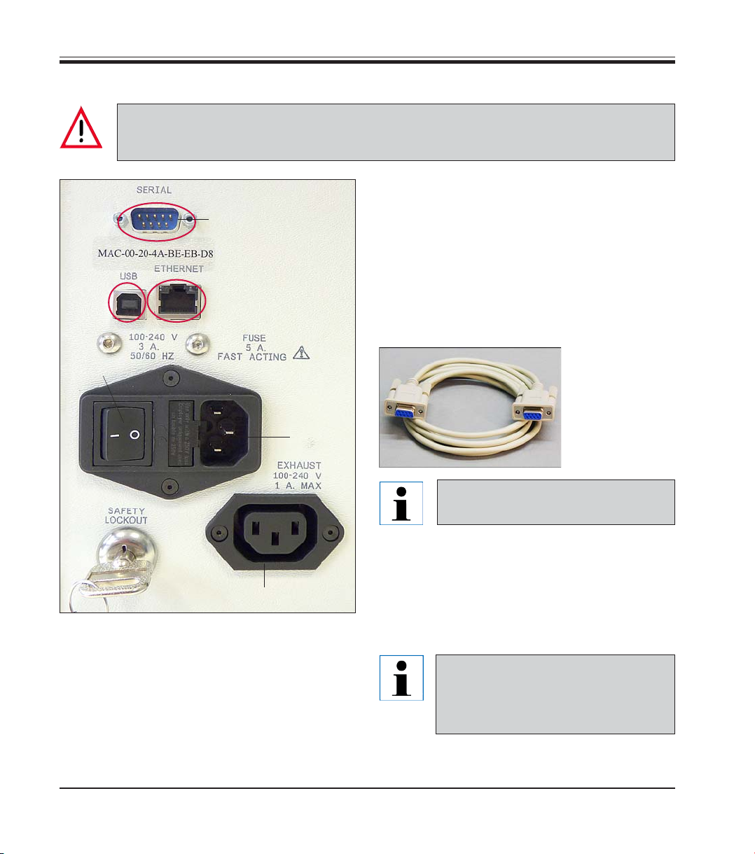
4.8 Electrical connection
The instrument MUST be connected to a grounded power socket.
The instrument is delivered with two different power cables. be sure to use only the one that is
appropriate for the local power supply (plug must fit on-site wall outlet).
12
14
16
15
18
There are 3 options for establishing a data connection:
• Serial (12), cable in standard delivery - easiest method
• USB (14), cable in standard delivery
• Ethernet (15), cable in standard delivery
• To use the printer, a serial data cable is required (36, part of standard delivery).
• Connect the
cable to
printer port
36
(12).
Fig. 20
16a
20
Fig. 19
Connecting to power supply
• Make sure the printer is switched OFF - power switch ( ) set to "0" = OFF.
• Insert the correct power cord into the power
input socket (18).
• Switch on power switch (switch to position
"I" = ON).
24
For other options, refer to the software
installation manual.
Establishing the connection between the printer
and filter unit
• Plug the power cable (35, Fig. 12) into the input socket of the filter unit - plug the other end
of the cable into the input socket (20) of the
printer.
Once the instrument has been
switched for the first time (turning
clockwise), the key switch (16a)
should always remain in this position.
Operating Manual V 1.0 – 06/2010
Page 25
To keep your Cassette Printer operating properly it is critical that the following parts are cleaned biweekly.
• Laser lens
• Area around the laser lens
• Filter system inlet openings
• Optical sensors
• After this routine maintenance is completed, the user must check the Cassette Printer for
damage.
• If the Cassette Printer is damaged, stop using the Cassette Printer immediately and contact
the Leica service technician for information on replacement.
5.1 Cleaning the laser lens
A clean laser lens ensures readily legible imprints on the cassettes. To
clean the laser lens follow the following procedure:
5. Cleaning and Maintenance
26
Leica LPC
Locating the Laser Lens
• Unscrew the two knobs (26).
Laser lens is located directly behind the main
cover.
Fig. 21
25
Page 26

5. Cleaning and Maintenance
27
NEVER attempt to turn the lens unit (27)
manually.
Turning it manually causes long-term
damage to your Laser Cassette Printer.
Cleaning the Laser Lens
Fig. 22
IMPORTANT! Use only 5%-8% acetic
acid with distilled water to clean the
laser lens.
All other solvents will permanently
damage the lens.
26
28
Fig. 23
To clean the laser lens (28) follow the following
procedure:
• Gauze pads in a size of 5 x 5 cm are best suited for lens cleaning.
• Moisten the gauze pad with 5%-8% acetic acid
with distilled water.
• Clean under the lens unit.
• Carefully wipe off the glass lens and the metal
parts around the lens.
• Ensure that the area where the glass and the
metal meet is cleaned carefully.
Operating Manual V 1.0 – 06/2010
Page 27

29a
29
5. Cleaning and Maintenance
5.2 Cleaning the filter inlet tubes
The filter system of the Cassette Printer MUST be cleaned every 2 weeks to
maintain proper function.
• The silver intake tube (29) is located inside the
main cover.
Cleaning the Intake Tube
The silver intake tube (29) and the exhaust shaft
(29a) collect dust if not cleaned every 2 weeks.
• Use a gauze pad in a size of 5 x 5 cm to clean
the intake tube and the area around the tube.
Leica LPC
Fig. 24
Wipe this area with a DRY gauze pad!
• Then, use a gauze pad moistened with 5%-8%
acetic acid (with distilled water) to clean the
intake tube and the area around the tube.
27
Page 28

5. Cleaning and Maintenance
5.3 Cleaning the optical sensors
The Optical Sensors allow the machine to know if it is loaded with cassettes.
If the sensors are covered with dust, the printer ceases to operate.
Locating and Cleaning the Sensors
• The location of the sensors is pointed out by the yellow arrows (Fig. 25
and Fig. 26).
• Sensors are located on both sides of the housing.
• Blow a little compressed air into this area to clean the optical sensors.
• You can obtain compressed air in cans at your local office supply store.
Fig. 26
Fig. 25
Be sure not to ice over the sensors with the compressed air.
The sensors will need biweekly
cleaning.
28
Operating Manual V 1.0 – 06/2010
Page 29

5. Cleaning and Maintenance
CAUTION: Always use dry gauze to
clean the main laser system.
If liquids drip into the motor or other
electrical parts, long-term damage to
your Laser Cassette Printer will result.
5.4 Changing the filters
Filters in the Filtration System must be changed periodically to ensure safe
and reliable operation of your LPC Laser Cassette Printer.
The filter unit contains two filters: the prefilter and the main filter.
IMPORTANT!IMPORTANT!
IMPORTANT! Use only prefilter bags and main filter cartridges recommended by Leica. Other
IMPORTANT!IMPORTANT!
filters may hamper the airflow in the filter unit, or may not be able to remove all dust particles
from the exhaust. For further information, please contact your Leica representative.
Fig. 27
• Use DRY gauze to clean the area around the
main laser system carefully.
• Blow a little compressed air into this area to
clean the optical sensors.
Be sure not to ice over the sensors
with the compressed air.
Leica LPC
29
Page 30

5. Cleaning and Maintenance
5.4.1 Replacing the prefilter
The prefilter bag must be changed after every 10,000 - 15,000 cassettes - depending on the type of laser printing (positive or inverted) - or 1x a year.
If the laser printer detects a reduction of the air flow rate, an audible signal is
sounded by the filter unit and you see the following message on the monitor.
When either condition (warning or beeping) is present the user must
change the prefilter bag.
In the case of the warning, click OK on the warning massage window after
you have changed the filter to reset the counter back to zero. If you click the
Cancel button, the window is closed, but the window reappears after the
next cassette is printed.
Fig. 28
30
In the case of the beeping, changing the prefilter bag should stop the beeping.
If this is not the case, contact your Leica service technician!
Operating Manual V 1.0 – 06/2010
Page 31

18
5. Cleaning and Maintenance
The prefilter is replaced by opening the prefilter compartment of the filter
unit and replacing the prefilter bag (17).
• Open the prefilter compartment by pulling the tube end (18) of the plastic
cover (19).
19
17
To replace the filter, turn it counterclockwise as
shown above and pull it off. Remove the filter
bag carefully and dispose of it according to the
regulations applicable in the country of use.
Fit the new filter bag over the Allen screws and
fasten it in place by clamping/turning clockwise.
Leica LPC
Fig. 29
1. After installing the new filter bag, first fasten the lower part of the cover
to the metal plate.
• The lower side of the cover has 2 metal tabs that must be inserted into
the slots on the bottom of the plastic cover.
If the metal tabs are not inserted into the slots in the plastic
cover, the cover will break.
31
Page 32

5. Cleaning and Maintenance
2. Then tilt the tube end on the cover towards the metal plate to ensure
secure closing.
3. Make sure that the prefilter bag does not get crushed between the plastic cover and the metal plate and become damaged.
· This causes the filter to lose vacuum and releases harmful dust particles.
Do not operate the LP C Laser Cassette Printer without ensuring
that the filter unit is properly connected and running. Otherwise, the instrument will malfunction and expel harmful dust
particles.
5.4.2 Replacing the main filter
The main filter must be replaced once a year or after printing
100,000- 120,000 LPC cassettes, or if the following message appears on the
monitor.
32
Fig. 30
Operating Manual V 1.0 – 06/2010
Page 33

5. Cleaning and Maintenance
21
32
32
21
32
8
To replace the main filter:
• Pull the hose ends off of the intake spouts (32).
• Unscrew the four knurled screws (8, see also
Fig. 8, page 16) at the top of the filter housing
and remove the top cover (21) of the filter unit.
Fig. 31
Leica LPC
33
Page 34

5. Cleaning and Maintenance
22
• Remove the filter cartridge (22) by reaching
into the opening with both hands and pulling it
upwards and out.
Fig. 32
When the main filter is installed the top
of the filter should be marked by the
user with the recommended replacement date. (Is visible when the cover of
the main filter unit is removed.)
Fig. 33
34
Bottom of
the main
filter
Fig. 34
• Replace the old main filter with a new one and
mark the top of the filter with the date for the
next replacement.
IMPORTANT: So that the main filter is
installed correctly, point the blower
inlet to the main filter outlet that is located at the bottom of the main filter.
Operating Manual V 1.0 – 06/2010
Page 35

5.5 Replacing fuses
5. Cleaning and Maintenance
Before replacing the secondary fuses, always switch the instrument off first and unplug it from the power supply.
The fuses are located on the rear of the instrument.
40
17
Fig. 34
• Using a screwdriver (40), pry out the fuse insert (17) and remove it.
17
17a
Fig. 35
• Remove the defective fuse from the fuse holder (17) and replace it with a replacement fuse
(17a).
Fuse: F 5AL 250 V
• Replace the fuse insert with the replacement
fuse until it clicks into place audibly.
Leica LPC
35
Page 36

6. Optional Accessories
Touch PC, 10" ................................................................................................................................. 14 0605 46855
Touch PC holder ........................................................................................................................... 14 0605 46856
Scanner .......................................................................................................................................... 14 0605 46818
Scanner holder ............................................................................................................................. 14 0605 46819
Printer software:
NLG-PrintMan
NiceLabel (German) ............................................................................................................... 14 0601 38470
NiceLabel (English) ................................................................................................................. 14 0601 45690
LPC cassettes
Tissue cassettes
Color: aqua ............................................................................................................................... 14 0605 46825
Color: blue ................................................................................................................................ 14 0605 46826
Color: green ............................................................................................................................. 14 0605 46827
Color: purple ............................................................................................................................ 14 0605 46828
Color: peach ............................................................................................................................. 14 0605 46829
Color: pink ................................................................................................................................ 14 0605 46830
Color: white .............................................................................................................................. 14 0605 46831
Color: yellow ............................................................................................................................ 14 0605 46832
Color: gray ................................................................................................................................ 14 0605 46925
Color: orange ........................................................................................................................... 14 0605 46926
Color: brown ............................................................................................................................ 14 0605 46927
Biopsy cassettes
Color: aqua ............................................................................................................................... 14 0605 46833
Color: blue ................................................................................................................................ 14 0605 46834
Color: green ............................................................................................................................. 14 0605 46835
Color: purple ............................................................................................................................ 14 0605 46836
36
Operating Manual V 1.0 – 06/2010
Page 37

6. Optional Accessories
Color: peach ............................................................................................................................. 14 0605 46837
Color: pink ................................................................................................................................ 14 0605 46838
Color: white .............................................................................................................................. 14 0605 46839
Color: yellow ............................................................................................................................ 14 0605 46840
Color: gray ................................................................................................................................ 14 0605 46928
Color: orange ........................................................................................................................... 14 0605 46929
Color: brown ............................................................................................................................ 14 0605 46930
Fine-mesh tissue cassettes
Color: aqua ............................................................................................................................... 14 0605 46845
Color: blue ................................................................................................................................ 14 0605 46846
Color: green ............................................................................................................................. 14 0605 46847
Color: purple ............................................................................................................................ 14 0605 46848
Color: peach ............................................................................................................................. 14 0605 46849
Color: pink ................................................................................................................................ 14 0605 46850
Color: white .............................................................................................................................. 14 0605 46851
Color: yellow ............................................................................................................................ 14 0605 46852
Color: gray ................................................................................................................................ 14 0605 46931
Color: orange ........................................................................................................................... 14 0605 46932
Color: brown ............................................................................................................................ 14 0605 46933
Linear Magazine Kit ..................................................................................................................... 14 0605 46657
Filter bag (prefilter), 5 pcs. .......................................................................................................... 14 0605 46816
Main filter, GD80 HEPA filter-Imag ............................................................................................ 14 0605 46817
Leica LPC, Laser Cassette Printer
37
Page 38

7. Appendix A – Laser Safety
7.1 Laser hazard classes
The intent of laser hazard classification is to provide clear distinction of the lasers’ properties
and hazards to users so appropriate protective measures can be taken. Classification is based on
the maximum output available for the intended use. Specific labeling requirements indicate that
the class of the laser as well as the emission wavelength(s) and any other applicable precautionary instructions must be included on any signage. Laser classification is also used for determining requirements for medical surveillance for those individuals working with and around lasers.
The US standard for laser safety [21 CFR 1040.10], the ANSI standard [ANSI Z136.1] and the international standard [EN 60825] classify lasers into five different hazard categories. These classes
are based upon the combination of wavelength range, power, and emission duration, which are
used to determine the level of risk and the potential to cause biological damage to the eye or
skin.
The definitions compiled from ANSI Z136.1 are as follows:
The Leica LPC Laser Cassette Printer, Model LPC is rated as follows:
• CLASS 1 laser product using a CLASS 4
(5 W, 10.57 – 10.63 µm)
embedded laser
38
• Class 1:
Any laser, or laser system containing a laser, with wavelength ranges from Ultraviolet through
Far Infrared (180 nm – 100,000 nm +), that cannot emit laser radiation levels exceeding
Class 1 Accessible Emission Limits (AEL) as defined by ANSI Z136.1. For example this would
compute to exposure (for a 48-hour period) for a 488 nm laser of no greater than 0.2 mW.
Basically, the laser radiation level emitted by a device classified as Class 1 produces no hazard whatsoever to the user during normal operation. Presently, Class 1 lasers and laser systems are exempt from all control measures. The Class 1 designation does not apply during
times of maintenance or service where the safety controls of the device are defeated or
otherwise removed. The Class 1 environment resumes once the device is returned to its original state with all safety devices properly reconnected.
Operating Manual V 1.0 – 06/2010
Page 39

7. Appendix A – Laser Safety
••
• Class 2:
••
This classification applies only to continuous wave (CW) and repetitive-pulse lasers and
laser systems of the visible part of the electromagnetic spectrum (400 – 700 nm) that exceed
Class 1 levels, but do not exceed an average radiant power of 1 mW.
••
• Class 3a:
••
Lasers and laser systems that have an accessible output between one and five times the
Class 1 AEL for wavelengths shorter than 400 nm or longer than 700 nm, or less than five
times the Class 2 AEL for wavelengths between 400 and 700 nm. Lasers of this class have
intermediate power ranges of 1 - 5 mW.
••
• Class 3b:
••
Lasers and laser systems having the power range between 5 - 500 mW. This applies to lasers with wavelength ranges from Ultraviolet through Far Infrared (180 nm – 100,000 nm +).
These lasers or laser systems can produce a hazard if viewed directly, and may produce an
eye hazard when viewing diffuse reflections off of a shiny surface at angles of less than
5 degrees from the source, however Class 3b lasers should not produce a hazardous diffuse
reflection from a matte (not shiny) surface.
••
• Class 4:
••
Lasers and laser systems having power greater than 500 mW. This applies to lasers with
wavelength ranges from Ultraviolet through Far Infrared (180 nm – 100,000 nm +). This class
of laser poses the greatest hazard, and any and all precautions should be taken to protect
oneself from exposure to direct or diffuse laser radiation. Direct exposure to the eye from
this class of laser can cause permanent damage. Stray beams are potential fire hazards and
combustible material should be kept out of beam paths at all times.
Leica LPC
ANSI Z136.1 requires specific control measures for each laser classification and the environment in which they are used. The chart above lists some of the requirements that
may need to be implemented in a laboratory setting. The Biosystems Laser Safety Officer, or designee, should reference the applicable safety regulations for appropriate control measures to implement in the area the instrument will be used.
39
Page 40

7. Appendix A – Laser Safety
7.2 Inspection measures for laser classes
Inspection measure Class 1 Class 2 Class 3a Class 3b Class 4
Activation of
warning systems
Interior laser XE
optics laser
Controlled area
Labels
Area Posting
Standard operating
mode
Education and
training
No requirement.
No requirement.
Shall have.
No requirement.
No requirement.
No requirement.
No requirement.
No requirement.
Shall have.
No requirement.
No requirement.
Should
have.
No requirement.
No requirement.
Shall have.
Should
have.
No requirement.
Should
have.
Should have.
Shall have.
Nominal Hazard
Zone analysis
required.
Shall have.
Shall have.
Nominal Hazard
Zone analysis
required.
Should have.
Shall have.
Shall have.
Shall have.
Nominal Hazard
Zone analysis
required.
Shall have.
Shall have.
Nominal Hazard
Zone analysis
required.
Shall have.
Shall have.
Authorized
personnel
Warning signs and
labels
40
No requirement.
No requirement.
No requirement.
Should
have.
No requirement.
Should
have.
Shall have.
Shall have.
Nominal Hazard
Zone analysis
required.
Operating Manual V 1.0 – 06/2010
Shall have.
Shall have.
Nominal Hazard
Zone analysis
required.
Page 41

7.3 Biological effects of laser beams
7.3.1 Eye injuries
Because of the high degree of beam collimation, a laser serves as an almost
ideal point source of intense light. A laser beam of sufficient power can theoretically produce retinal intensities at magnitudes that are greater than
conventional light sources, and even larger than those produced when directly viewing the sun. Eye exposure to a direct beam can cause permanent
eye damage including blindness. Protective eyewear should always be
worn when potential exposure to direct laser beams exist.
• Due to the lens-like focusing effect of the human eye, it is 100,000 times
more susceptible to injury than the skin.
• The laser protective eyewear must always be available for the wavelengths of the laser used.
• However, with regard to protection from laser radiation, eye protection
equipment is the last step in the process. Engineering and administrative
controls are the first step.
• Do not wear jewelry when working with an open laser beam to prevent
the beam from being reflected in uncertain directions.
• If possible, use all protective housings, locking mechanisms and guards.
• Always use laser protective eyewear when repairing, aligning or installing lasers or whenever a laser safeguard is not present.
7. Appendix A – Laser Safety
7.3.2 Thermal injury
Leica LPC
The most common cause of laser-induced tissue damage is thermal in nature, where the tissue proteins are denatured due to the temperature rise
following absorption of laser energy.
The thermal damage process (resulting in burns) is generally associated
with lasers operating at exposure times greater than 10 microseconds and
in the wavelength region from the near ultraviolet to the far infrared. Tissue
damage may also be caused by thermally induced acoustic waves following
exposures to sub-microsecond laser exposures.
41
Page 42

7. Appendix A – Laser Safety
7.3.3 Skin injuries
Radiation in the UVA (315-400 nm) range can cause hyperpigmentation and
erythema (sunburn). Exposure in the UVB (280-315 nm) range is most injurious to skin. In addition to thermal injury caused by ultraviolet energy, there
is also possibility of radiation carcinogenesis from UVB. The shorter wavelengths are absorbed in the outer dead layers of the epidermis (stratum corneum) and the longer wavelengths have an initial pigment-darkening effect
followed by erythema if there is exposure to excessive levels.
The dangers associated with exposure to the skin to radiation are less severe than the eye injuries; however, with the increasingly widespread use of
powerful laser systems, particularly ultraviolet lasers, the skin of personnel
can be exposed to hazardous levels of radiation if they are used in non-encapsulated systems.
Skin burns caused by lasers can happen quite fast and with great intensity.
Protective clothing should be worn when potential exposure to direct laser
beams exist.
• Radiation in the UVC (200-280 nm) range can cause erythema (sunburn),
skin cancer and burns.
• Radiation in the UVB (280-315 nm) range can cause accelerated skin
aging, increased skin pigmentation and burns.
• Radiation in the UVA (315-400 nm) range can cause pigment darkening
and skin burns.
• Visible radiation (400-700 nm) can cause photosensitive reactions and
skin burns.
• Infrared radiation (700-100,000 nm) can cause skin burns.
42
Operating Manual V 1.0 – 06/2010
 Loading...